WO2018146792A1 - 蒸気タービン、仕切部材、および蒸気タービンの運転方法 - Google Patents
蒸気タービン、仕切部材、および蒸気タービンの運転方法 Download PDFInfo
- Publication number
- WO2018146792A1 WO2018146792A1 PCT/JP2017/004910 JP2017004910W WO2018146792A1 WO 2018146792 A1 WO2018146792 A1 WO 2018146792A1 JP 2017004910 W JP2017004910 W JP 2017004910W WO 2018146792 A1 WO2018146792 A1 WO 2018146792A1
- Authority
- WO
- WIPO (PCT)
- Prior art keywords
- pressure
- partition
- pressure stage
- steam
- low
- Prior art date
- Legal status (The legal status is an assumption and is not a legal conclusion. Google has not performed a legal analysis and makes no representation as to the accuracy of the status listed.)
- Ceased
Links
Images




Classifications
-
- F—MECHANICAL ENGINEERING; LIGHTING; HEATING; WEAPONS; BLASTING
- F01—MACHINES OR ENGINES IN GENERAL; ENGINE PLANTS IN GENERAL; STEAM ENGINES
- F01K—STEAM ENGINE PLANTS; STEAM ACCUMULATORS; ENGINE PLANTS NOT OTHERWISE PROVIDED FOR; ENGINES USING SPECIAL WORKING FLUIDS OR CYCLES
- F01K7/00—Steam engine plants characterised by the use of specific types of engine; Plants or engines characterised by their use of special steam systems, cycles or processes; Control means specially adapted for such systems, cycles or processes; Use of withdrawn or exhaust steam for feed-water heating
- F01K7/34—Steam engine plants characterised by the use of specific types of engine; Plants or engines characterised by their use of special steam systems, cycles or processes; Control means specially adapted for such systems, cycles or processes; Use of withdrawn or exhaust steam for feed-water heating the engines being of extraction or non-condensing type; Use of steam for feed-water heating
- F01K7/38—Steam engine plants characterised by the use of specific types of engine; Plants or engines characterised by their use of special steam systems, cycles or processes; Control means specially adapted for such systems, cycles or processes; Use of withdrawn or exhaust steam for feed-water heating the engines being of extraction or non-condensing type; Use of steam for feed-water heating the engines being of turbine type
-
- F—MECHANICAL ENGINEERING; LIGHTING; HEATING; WEAPONS; BLASTING
- F01—MACHINES OR ENGINES IN GENERAL; ENGINE PLANTS IN GENERAL; STEAM ENGINES
- F01D—NON-POSITIVE DISPLACEMENT MACHINES OR ENGINES, e.g. STEAM TURBINES
- F01D17/00—Regulating or controlling by varying flow
- F01D17/10—Final actuators
- F01D17/12—Final actuators arranged in stator parts
- F01D17/14—Final actuators arranged in stator parts varying effective cross-sectional area of nozzles or guide conduits
- F01D17/141—Final actuators arranged in stator parts varying effective cross-sectional area of nozzles or guide conduits by means of shiftable members or valves obturating part of the flow path
- F01D17/145—Final actuators arranged in stator parts varying effective cross-sectional area of nozzles or guide conduits by means of shiftable members or valves obturating part of the flow path by means of valves, e.g. for steam turbines
-
- F—MECHANICAL ENGINEERING; LIGHTING; HEATING; WEAPONS; BLASTING
- F01—MACHINES OR ENGINES IN GENERAL; ENGINE PLANTS IN GENERAL; STEAM ENGINES
- F01D—NON-POSITIVE DISPLACEMENT MACHINES OR ENGINES, e.g. STEAM TURBINES
- F01D25/00—Component parts, details, or accessories, not provided for in, or of interest apart from, other groups
- F01D25/24—Casings; Casing parts, e.g. diaphragms, casing fastenings
-
- F—MECHANICAL ENGINEERING; LIGHTING; HEATING; WEAPONS; BLASTING
- F01—MACHINES OR ENGINES IN GENERAL; ENGINE PLANTS IN GENERAL; STEAM ENGINES
- F01D—NON-POSITIVE DISPLACEMENT MACHINES OR ENGINES, e.g. STEAM TURBINES
- F01D9/00—Stators
- F01D9/02—Nozzles; Nozzle boxes; Stator blades; Guide conduits, e.g. individual nozzles
- F01D9/04—Nozzles; Nozzle boxes; Stator blades; Guide conduits, e.g. individual nozzles forming ring or sector
-
- F—MECHANICAL ENGINEERING; LIGHTING; HEATING; WEAPONS; BLASTING
- F01—MACHINES OR ENGINES IN GENERAL; ENGINE PLANTS IN GENERAL; STEAM ENGINES
- F01K—STEAM ENGINE PLANTS; STEAM ACCUMULATORS; ENGINE PLANTS NOT OTHERWISE PROVIDED FOR; ENGINES USING SPECIAL WORKING FLUIDS OR CYCLES
- F01K7/00—Steam engine plants characterised by the use of specific types of engine; Plants or engines characterised by their use of special steam systems, cycles or processes; Control means specially adapted for such systems, cycles or processes; Use of withdrawn or exhaust steam for feed-water heating
- F01K7/16—Steam engine plants characterised by the use of specific types of engine; Plants or engines characterised by their use of special steam systems, cycles or processes; Control means specially adapted for such systems, cycles or processes; Use of withdrawn or exhaust steam for feed-water heating the engines being only of turbine type
- F01K7/18—Steam engine plants characterised by the use of specific types of engine; Plants or engines characterised by their use of special steam systems, cycles or processes; Control means specially adapted for such systems, cycles or processes; Use of withdrawn or exhaust steam for feed-water heating the engines being only of turbine type the turbine being of multiple-inlet-pressure type
- F01K7/20—Control means specially adapted therefor
-
- F—MECHANICAL ENGINEERING; LIGHTING; HEATING; WEAPONS; BLASTING
- F01—MACHINES OR ENGINES IN GENERAL; ENGINE PLANTS IN GENERAL; STEAM ENGINES
- F01K—STEAM ENGINE PLANTS; STEAM ACCUMULATORS; ENGINE PLANTS NOT OTHERWISE PROVIDED FOR; ENGINES USING SPECIAL WORKING FLUIDS OR CYCLES
- F01K7/00—Steam engine plants characterised by the use of specific types of engine; Plants or engines characterised by their use of special steam systems, cycles or processes; Control means specially adapted for such systems, cycles or processes; Use of withdrawn or exhaust steam for feed-water heating
- F01K7/34—Steam engine plants characterised by the use of specific types of engine; Plants or engines characterised by their use of special steam systems, cycles or processes; Control means specially adapted for such systems, cycles or processes; Use of withdrawn or exhaust steam for feed-water heating the engines being of extraction or non-condensing type; Use of steam for feed-water heating
- F01K7/345—Control or safety-means particular thereto
-
- F—MECHANICAL ENGINEERING; LIGHTING; HEATING; WEAPONS; BLASTING
- F05—INDEXING SCHEMES RELATING TO ENGINES OR PUMPS IN VARIOUS SUBCLASSES OF CLASSES F01-F04
- F05D—INDEXING SCHEME FOR ASPECTS RELATING TO NON-POSITIVE-DISPLACEMENT MACHINES OR ENGINES, GAS-TURBINES OR JET-PROPULSION PLANTS
- F05D2220/00—Application
- F05D2220/30—Application in turbines
- F05D2220/31—Application in turbines in steam turbines
-
- F—MECHANICAL ENGINEERING; LIGHTING; HEATING; WEAPONS; BLASTING
- F05—INDEXING SCHEMES RELATING TO ENGINES OR PUMPS IN VARIOUS SUBCLASSES OF CLASSES F01-F04
- F05D—INDEXING SCHEME FOR ASPECTS RELATING TO NON-POSITIVE-DISPLACEMENT MACHINES OR ENGINES, GAS-TURBINES OR JET-PROPULSION PLANTS
- F05D2260/00—Function
- F05D2260/60—Fluid transfer
- F05D2260/606—Bypassing the fluid
Definitions
- the present invention relates to a steam turbine provided with a bleed or mixed pressure regulating valve, a partition member for partitioning a high pressure portion and a low pressure portion in a passenger compartment, and a method for operating the steam turbine.
- a steam turbine is known that can extract steam that expands while rotating a rotor in a passenger compartment to the outside in the middle of the process (for example, Patent Document 1).
- a high-pressure stage and a low-pressure stage are partitioned by a partition plate or a wall of a passenger compartment, and a part of the steam that has passed through the high-pressure stage is taken out as bleed air, and the rest passes through a pressure regulating valve. It is designed to be introduced by a nozzle.
- the operation of the steam turbine can be controlled by adjusting the pressure regulating valve and the steam regulating valve that regulates the flow rate of the steam supplied to the high-pressure stage by the control device.
- valves As a pressure regulating valve, there are a plurality of valves that are stacked on the partition plate and have a window formed and use a rotatable grid valve (Patent Document 2), as well as a plurality of valves located on the outer peripheral side of the partition plate. And a flow path that is divided so as to correspond to these valves is employed.
- Patent Document 2 rotatable grid valve
- the pressure regulating valve can also function as a mixed pressure regulating valve. That is, it may be configured such that surplus steam flows from the outside into the steam that has passed through the high pressure stage as a mixed gas, and the mixed steam is introduced into the low pressure stage through the pressure regulating valve and the nozzle.
- the flow path of the pressure regulating valve is divided into a plurality of valves, and a plurality of valves individually corresponding to the flow path sections Is preferably used.
- the plurality of valves are arranged at positions away from the outer end of the partition plate.
- the flow path uses the entire circumference of the partition plate from the position of multiple valves to the inner end of the partition plate.
- the case of the pressure regulating valve becomes enormous, leading to an increase in the size of the apparatus.
- the entire amount of the steam introduced from the high pressure stage to the low pressure stage flows through the adjustment valve, and the flow rate of the steam introduced into the low pressure stage is adjusted by the adjustment valve.
- the regulating valve cannot be fully closed.
- the amount of steam that is reserved for cooling the low-pressure stage always passes through the pressure regulator, and there is no need to adjust the flow rate, so it flows through the pressure regulator. It can be said that there is no meaning.
- the present invention is a configuration in which the pressure regulating valve is arranged in a region including the outer peripheral side from the partition portion, and can be downsized, a partition member provided in the steam turbine, and
- An object is to provide a method for operating the steam turbine.
- the steam turbine of the present invention includes a partition that partitions a high-pressure stage to which steam is supplied and a low-pressure stage to which steam that has passed through the high-pressure stage is introduced, and the pressure of extraction air that is part of the steam that has passed through the high-pressure stage, or high pressure
- a pressure regulating valve pressure regulating valve capable of adjusting the pressure of the air-fuel mixture flowing from the outside into the steam that has passed through the stage.
- the pressure regulating valve is located on the outer peripheral side of the partition part, and corresponds to each of the plurality of flow rate control valves and the plurality of flow rate control valves through which steam is guided from the high pressure stage side of the partition part. And a plurality of flow channel sections communicating with each other through the nozzle holes.
- the plurality of flow path sections are generally disposed in the circumferential direction of the partition section in a region including the outer peripheral side of the partition section.
- the present invention is characterized in that the partition portion is provided with a bypass passage that allows the high-pressure stage side and the low-pressure stage side to communicate with each other without going through the pressure regulating valve.
- the pressure regulating valve includes a flow path that guides the steam from the high-pressure stage side to a predetermined position that is spaced radially outward from the outer end of the partition portion, and a plurality of valves that are disposed at the predetermined positions. And a plurality of flow passage sections that guide the steam that has passed through the flow adjustment valve to the low-pressure stage, and the plurality of flow passage sections are arranged in parallel from the position of the plurality of flow adjustment valves toward the partition portion.
- nozzle vapor nozzle
- the partition portion is formed integrally with the vehicle compartment that accommodates the high-pressure stage and the low-pressure stage, or is a partition member that is separate from the vehicle compartment and faces the high-pressure stage.
- a high-pressure section and a partition low-pressure section facing the low-pressure stage, and the bypass channel communicates the high-pressure stage side with respect to the partition high-pressure section and a bypass gap located between the partition high-pressure section and the partition low-pressure section It is preferable to include an opening and a steam bypass introduction path that leads from the bypass gap to the low-pressure stage side.
- the partition portion is formed integrally with the vehicle compartment that accommodates the high-pressure stage and the low-pressure stage, or is a partition member that is separate from the vehicle compartment and faces the high-pressure stage.
- a high-pressure part and a partition low-pressure part facing the low-pressure stage, and the bypass channel communicates the high-pressure stage side with respect to the partition high-pressure part and a second part located between the partition high-pressure part and the partition low-pressure part It is preferable that it is comprised including the opening to be made and the nozzle hole which leads to the low pressure stage side from the 2nd part.
- a plurality of openings are distributed over the entire circumference or part of the partition high-pressure part.
- the steam turbine of the present invention includes a control unit that increases or decreases the opening degree of each of the plurality of flow rate adjustment valves, and the control unit is configured to obtain a plurality of flow rates from the minimum flow rate when all of the plurality of flow rate adjustment valves are fully closed. It is preferable that the flow rate of the steam introduced into the low pressure stage through the pressure regulating valve can be adjusted up to the maximum flow rate when any of the flow rate regulating valves is fully opened.
- the present invention relating to a partition member for a steam turbine is a partition member that partitions a high-pressure stage to which steam is supplied from a low-pressure stage to which steam that has passed through the high-pressure stage is introduced, and is configured to reduce the pressure of bleed or mixed air.
- a partition member for a steam turbine according to the present invention includes a partition high-pressure portion that faces a high-pressure stage and a partition low-pressure portion that faces a low-pressure stage, and the bypass path is separated from the partition high-pressure portion by a high-pressure stage side. It is preferable to include an opening for communicating with the gap between the high-pressure part and the partitioning low-pressure part, and a steam nozzle leading from the gap to the low-pressure stage side.
- a plurality of openings are distributed over the entire circumference or part of the partition high-pressure part.
- the present invention can adjust the pressure of the bleed air that is part of the steam that has passed through the high-pressure stage and the partition that partitions the high-pressure stage to which the steam is supplied from the low-pressure stage to which the steam that has passed through the high-pressure stage is introduced.
- a steam turbine having a pressure regulating valve, and adjusting a flow rate of steam introduced into the low pressure stage through a pressure regulating valve disposed in a region including the outer peripheral side of the partition portion. While controlling the pressure and always rotating the high-pressure stage and the low-pressure stage, it is possible to introduce steam from the high-pressure stage side to the low-pressure stage side through the bypass passage provided in the partition without passing through the pressure regulating valve.
- the present invention can adjust the pressure of the air-fuel mixture that flows from the outside into the partition that partitions the high-pressure stage to which the steam is supplied and the low-pressure stage to which the steam that has passed through the high-pressure stage is introduced, and the steam that has passed through the high-pressure stage
- a steam turbine operating method comprising: a pressure regulating valve, wherein the flow rate of steam introduced into the low pressure stage is adjusted by a pressure regulating valve disposed in a region including the outer peripheral side of the partition portion.
- the low pressure stage is passed through the bypass. It is preferable to secure a predetermined flow rate of the steam introduced into the low pressure stage by the steam introduced into the side.
- the flow rate of the steam passing through the pressure regulating valve is reduced by the amount of the steam passing through the bypass path from the high pressure stage side to the low pressure stage side. It is possible to reduce the size of the steam turbine by suppressing the flow passage cross-sectional area of the pressure regulating valve disposed in the entire circumferential direction. In addition, since there is a bypass path for introducing steam to the low pressure stage without going through the pressure regulating valve, it is possible to ensure the flow rate of steam necessary for cooling the low pressure stage even when the pressure regulating valve fails.
- FIG. 1 It is a figure showing typically the steam turbine concerning the embodiment of the present invention.
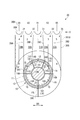
- the partition plate and its periphery are shown broken away.
- FIG. 1 shows typically the steam turbine which concerns on the modification of this invention.
- the partition wall of the passenger compartment and its periphery are shown broken away.
- a steam turbine 1 shown in FIG. 1 includes a rotor 2, a casing 3 that houses the rotor 2, a steam supply valve 4 that supplies steam to the inside of the casing 3, and a partition plate 10 that partitions the interior of the casing 3 ( (Partition part), the pressure regulation valve 30, and the control apparatus 5 (control part) are provided.
- the steam turbine 1 rotates the rotor 2 by injecting steam supplied into the vehicle compartment 3 through a steam supply valve 4 from a boiler or the like (not shown) to the blade, and the rotational power of the rotor 2 is not shown.
- a high-pressure stage 101 is configured to include a moving blade (not shown) fixed to the rotor 2 and rotating together with the rotor 2 and a stationary blade (not shown) provided on the inner wall of the casing 3.
- the low-pressure stage 102 includes the moving blade and the stationary blade.
- the partition plate 10 partitions the high pressure stage 101 and the low pressure stage 102, and stands up so as to be orthogonal to the axis 2 ⁇ / b> A of the rotor 2.
- Each of the high pressure stage 101 and the low pressure stage 102 includes a plurality of moving blades and a plurality of stationary blades, and is configured in multiple stages. Since the steam expands while being injected from the high-pressure stage 101 to the low-pressure stage 102, the low-pressure stage 102 has a larger diameter than the high-pressure stage 101.
- the rotating shaft 22 extending in the horizontal direction along the axis 2A of the rotor 2 is rotatably supported by journal bearings 23 and 24 positioned at both ends of the rotating shaft 22, and is a thrust bearing positioned at one end. 25 in the thrust direction.
- a generator or the like is connected to the other end side of the rotating shaft 22.
- the vehicle interior 3 includes a steam inlet 3A through which high-temperature and high-pressure steam flows into the first stage of the high-pressure stage 101, a steam outlet 3B through which steam flows out from the final stage of the low-pressure stage 102, and the high-pressure stage 101 and the low-pressure stage. And a port 3C for extracting or mixing air that allows steam to enter and exit between 102.
- the steam supply valve 4 provided at the upper part of one end side (upstream side) of the passenger compartment 3 can adjust the flow rate of the steam supplied to the high pressure stage 101 through the steam inlet 3A.
- an outlet passage portion 3D is provided so as to protrude from the passenger compartment 3 to the outer peripheral side.
- the steam supply valve 4 supplies high-temperature and high-pressure steam flowing in from an input port 4A connected to a boiler or the like to the high-pressure stage 101 in the passenger compartment 3 through the steam inlet 3A.
- the steam supply valve 4 is configured to be capable of adjusting the flow rate of the steam supplied to the high pressure stage 101.
- a shut-off valve 7 that shuts off the supply of steam from the input port 4 ⁇ / b> A when the operation of the steam turbine 1 is stopped or in an emergency is disposed in front of the steam supply valve 4.
- the bleed and mixed air ports 3 ⁇ / b> C are open directly below the partition plate 10 in the outer circumferential direction.
- the pressure regulating valve 30 is disposed over the entire circumferential direction of the partition plate 10 in a region including the outer peripheral side of the partition plate 10. The pressure of the bleed air taken out to the outside of the vehicle compartment 3 through the port 3C and the pressure of the air-fuel mixture flowing from the outside to the inside of the vehicle compartment 3 through the port 3C can be adjusted by the pressure regulating valve 30.
- the flow rate of the steam passing through the steam supply valve 4 and the flow rate of the steam passing through the pressure regulating valve 30 are respectively adjusted, so that the steam turbine 1 corresponding to the rotational speed of the rotor 2 is adjusted.
- the output and the pressure of the bleed or mixture are adjusted.
- the partition plate 10 has a partition high-pressure part 11 that faces the high-pressure stage 101 and a partition low-pressure part 12 that faces the low-pressure stage 102, and is located inside the passenger compartment 3. is set up.
- the upper part of the partition plate 10 is accommodated in an accommodating portion 3E provided in the vehicle compartment 3.
- the partition plate 10 is a separate body from the vehicle compartment 3.
- the partition high-pressure part 11 and the partition low-pressure part 12 are connected via a connecting part 13 on the inner peripheral side, and are configured integrally.
- the partition plate 10 is an annular member formed in a substantially U-shaped cross section.
- a gap 14 is formed between the partition high-pressure portion 11 and the partition low-pressure portion 12 in the direction of the axis 2A.
- a lower end portion 10 ⁇ / b> A (FIG. 1) of the partition plate 10 is supported by the inner peripheral portion of the passenger compartment 3.
- the partition plate 10 is configured by a pair of halves so that a half body corresponding to half of the partition plate 10 is shown.
- the rotary shaft 22 is passed through a circular opening formed by the inner end 10 ⁇ / b> B of the partition plate 10.
- the inner end 10B of the partition plate 10 and the outer peripheral portion of the rotating shaft 22 constitute a labyrinth seal 10C (FIG. 1).
- the labyrinth seal 10C is not shown in FIGS.
- the steam on the high-pressure stage 101 side from the partition plate 10 passes through an open valve among the plurality of valves of the pressure regulating valve 30 and enters the gap 14 between the partition high-pressure part 11 and the partition low-pressure part 12. Inflow.
- the gap 14 is divided into a plurality of portions 141 to 145 in the circumferential direction by partition walls 14A to 14E provided between the partition high pressure portion 11 and the partition low pressure portion 12. .
- the ratio of each of the portions 141 to 145 divided by the partition walls 14A to 14E can be determined as appropriate.
- Each of the gap portions 141 to 145 communicates with a nozzle 15 (a nozzle) leading to the low pressure stage 102.
- Each of these portions 141 to 145 only needs to communicate with at least one nozzle 15.
- the nozzle 15 is provided in the partition low-pressure part 12 so as to penetrate the partition low-pressure part 12 in the thickness direction, and steam is injected from the nozzle 15 toward the first stage of the low-pressure stage 102.
- a plurality of through holes 181 penetrating in the thickness direction are formed in the partition high pressure portion 11.
- the through-hole 181 is indicated by a black dot.
- these through holes 181 constitute a bypass path 18 that directly communicates the high-pressure stage 101 side and the low-pressure stage 102 side.
- the pressure regulating valve 30 includes an upstream flow path 301 (FIG. 1) for guiding steam from the high pressure stage 101 side to the upper position X, a plurality of flow rate adjusting valves V1 to V5 (FIG. 2) disposed at the position X, A plurality of flow passage sections 31 to 35 (FIG. 2) corresponding to each of the flow rate adjusting valves V1 to V5, and a casing 300 (FIG. 1) that accommodates all the components of the pressure regulating valve 30 are provided.
- the casing 300 is fastened to the outer periphery of the passenger compartment 3.
- the upstream flow path 301 continues in the vicinity of the final stage of the high-pressure stage 101, a wall 301 ⁇ / b> A that rises across the housing part 3 ⁇ / b> E and the casing 300, the upper part of the partition high-pressure part 11, and the upper part thereof. It is partitioned between the plate 301B.
- the upstream flow path 301 is a position X where the steam having passed through the high-pressure stage 101 passes from the upper part in the passenger compartment 3 to the outer end 11A of the partition high-pressure part 11 and away from the outer end 11A to the outside in the radial direction of the partition plate 10.
- the upstream flow path 301 is located in front of the paper surface of FIG. 2, and the upper end of the upstream flow path 301 or the vicinity thereof corresponds to the position X.
- the flow rate adjusting valves V1 to V5 are arranged in the width direction D1 of the partition plate 10 at the position X as shown in FIG.
- the direction in which the flow rate adjusting valves V1 to V5 are arranged corresponds to the direction orthogonal to the paper surface of FIG.
- Each of the flow rate adjusting valves V1 to V5 has a valve body 30A and a valve rod 30B that supports the valve body 30A.
- the valve rod 30B is advanced and retracted by a drive mechanism (not shown), the dimension of the gap between the valve body 30A and a valve seat (not shown) changes, and the opening degree of each of the flow rate adjusting valves V1 to V5 changes.
- the flow path sections 31 to 35 guide the steam that has passed through the flow rate adjusting valves V1 to V5 to the low pressure stage 102, respectively.
- FIG. 2 shows numbers “1” to “5” corresponding to the flow path sections 31 to 35, respectively.
- the plurality of flow path sections 31 to 35 include first portions 31A, 32A, 33A, 34A, and 35A extending in parallel downward from the position of the flow rate adjusting valves V1 to V5 toward the partition plate 10, as described above. Further, portions 141 to 145 (hereinafter referred to as a second portion) in which the gap 14 between the partition high pressure portion 11 and the partition low pressure portion 12 is partitioned, and the nozzle 15 described above prepared for each of the flow path sections 31 to 35. It is comprised including.
- the flow path sections 31 to 35 are arranged over the entire periphery of the partition plate 10 in a region including the outer peripheral side of the partition plate 10 as a whole. Even if it is not possible to arrange the flow path sections 31 to 35 over the entire circumference because some member or the like is arranged around a part of the partition plate 10, a part in the circumferential direction Except for the above, it is assumed that the flow path sections 31 to 35 are disposed entirely in the circumferential direction of the partition plate 10 in the region including the outer peripheral side of the partition plate 10.
- the first portions 31A, 32A, 33A, 34A, and 35A are divided into a plurality in the width direction D1 between the above-described plate 301B (FIG. 1) and the outer wall of the casing 300 by partition walls 39A to 39D (FIG. 2). .
- the first portion 31A corresponding to the flow rate adjusting valve V1 located at the center in the width direction D1 extends downward toward the gap 14 between the partition wall 39B and the partition wall 39C, and continues to the second portion 141.
- the first portion 31A and the second portion 141 form a continuous flow path.
- the first portion 32A is continuous with the second portion 142
- the first portion 33A is continuous with the second portion 143.
- a first portion 34A corresponding to the flow rate adjusting valve V4 located at the left end in FIG. 2 is formed between the partition wall 39A and the outer wall of the casing 300 and on the left side of the gap 14 of the partition plate 10, and the second portion. 144 is continuous. That is, the flow path section 34 including the first portion 34A and the second portion 144 is partitioned by the partition wall 39A, the casing 300, the partition wall 14A in the gap 14, and the partition wall 39E located at the lower end inside the casing 300. ing.
- the first portion 35A corresponding to the flow rate adjusting valve V5 located at the right end is formed between the partition wall 39D and the outer wall of the casing 300 and on the right side of the gap 14 of the partition plate 10, and is continuous with the second portion 145. is doing.
- the flow passage sections 31 to 35 individually communicate with the low pressure stage 102 through the nozzles 15 (FIG. 3) provided in the second portions 141 to 145, respectively. Vapor that has passed through the open one is introduced into the low pressure stage 102 by the corresponding flow path sections 31-35.
- the steam that has passed through the flow regulating valve V1 flows into the first portion 31A and the second portion 141, and is introduced from the second portion 141 into the low pressure stage 102 through the nozzle 15.
- the opening degree of each of the plurality of flow rate adjusting valves V1 to V5 is increased or decreased based on a command sent from the control device 5 (FIG. 1) to the drive mechanism of the valve rod 30B.
- the flow rate of the steam introduced into the low pressure stage 102 can be adjusted as a whole of the pressure regulating valve 30 by individually increasing or decreasing the opening degree of each of the flow rate adjusting valves V1 to V5 by the control by the control device 5. For example, the flow rate adjustment valve V5 is fully opened, the flow rate adjustment valve V4 is opened at a predetermined opening degree, the remaining valves V1 to V3 are fully closed, and the flow rate adjustment valves V5, V4, V3, and V2 are fully open, The adjustment valve V1 is opened at a predetermined opening.
- the control device 5 can adjust the flow rate adjusting valves V1 to V1 to the required flow rates.
- the flow rate of the steam introduced into the low pressure stage 102 through the pressure regulating valve 30 can be adjusted from the minimum flow rate when all of V5 are fully closed to the maximum flow rate when all of V5 are fully opened.
- the steam supply valve 4 (FIG. 1) includes a plurality of flow rate adjustment valves and a plurality of flow passage sections divided in the circumferential direction, depending on the opening degree of each flow rate adjustment valve. Thus, the flow rate can be adjusted.
- the flow rate adjustment valves V1 to V4 of the pressure regulating valve 30 are fully closed and the flow rate adjustment valve V5 is fully closed.
- the opening is set close to closing, or when the flow regulating valves V1 to V5 of the pressure regulating valve 30 are fully closed due to a failure, the introduction of steam to the low pressure stage 102 through the pressure regulating valve 30 is blocked. There is.
- the minimum lift amount is set by providing a mechanical stopper in the flow rate adjusting valve V5 corresponding to the flow path section 35 of the pressure regulating valve 30, and the flow rate of steam necessary for constantly cooling the low pressure stage 102 is set. It is conceivable to secure. However, since the vapor
- the partition plate 10 is provided with a bypass path 18 (FIGS. 1 to 3) that allows the high-pressure stage 101 side and the low-pressure stage 102 side to communicate without passing through the pressure regulating valve 30.
- a bypass path 18 (FIGS. 1 to 3) that allows the high-pressure stage 101 side and the low-pressure stage 102 side to communicate without passing through the pressure regulating valve 30.
- this bypass 18 is always open, while the rotor 2 is rotating and steam is being supplied to the high pressure stage 101 through the steam supply valve 4, the bypass path 18 is not always passed through the pressure regulating valve 30 from the high pressure stage 101 side. Then, steam is introduced to the low pressure stage 102 side. Because of the bypass 18, it is not necessary to provide the pressure regulating valve 30 with a stopper for setting the minimum lift amount.
- the bypass 18 includes a through hole 181 (opening) that penetrates the partition high-pressure part 11 in the thickness direction, a gap 14 that communicates with the through hole 181, and a nozzle 15 (FIG. 2).
- the through holes 181 are distributed over the entire circumference of the partition high-pressure part 11.
- the opening area of each of these through holes 181 can be determined as appropriate in consideration of the flow rate of steam necessary for cooling the low pressure stage 102 through these through holes 181.
- the distribution of the illustrated through holes 181 is merely an example, and the positions of the plurality of through holes 181 can be determined as appropriate.
- a valve seat with a diffuser can be provided in the partition high-pressure portion 11 so that the opening of the bypass passage 18 can be provided in the partition high-pressure portion 11.
- This valve seat with a diffuser once squeezes the steam received from a wide inlet, then spreads it toward the outlet and jets it to the low pressure stage side.
- FIG 8 and 9 show an example (comparative example) in which the cooling steam to the low-pressure stage 102 is secured by setting the minimum lift amount in the flow rate adjustment valve V5 without providing the bypass passage 18.
- this comparative example there is no through-hole 181 in the partition high-pressure part 11, and the entire amount of steam introduced from the high-pressure stage 101 to the low-pressure stage 102 passes through the pressure regulating valve 30.
- the amount of steam passing through the pressure regulating valve 30 is smaller than that of the comparative example (FIGS. 8 and 9) by the amount of steam introduced into the low-pressure stage 102 through the bypass 18. Therefore, the cross-sectional area of the upstream flow path 301 of the pressure regulating valve 30 through which steam flows and the cross-sectional area of each of the flow path sections 31 to 35 can be made smaller than in the comparative example.
- the cross-sectional areas of the flow path sections 31 to 35 can be reduced in the radial direction (including the width direction D1) and the direction of the axis 2A.
- the flow rate adjusting valves V1 to V5 can also be reduced.
- the dimensions of the casing 300 in which the flow path and the valve body of the pressure regulating valve 30 of the present embodiment are built are smaller in both the axial line 2A direction and the radial direction than the dimension of the casing 300 ′ of the comparative example.
- the casing 300 is short in the direction of the axis 2A, so that the length of the rotating shaft 22 can be shortened, or a space for increasing the number of steps can be secured in the passenger compartment 3. If the length of the rotary shaft 22 is short, the diameter of the rotary shaft 22 can be reduced while securing rigidity, so that the size in the radial direction can be reduced and the cost of bearings and the like can be reduced.
- the flow passage cross-sectional area of the pressure regulating valve 30 can be reduced as the flow rate of the steam passing through the pressure regulating valve 30 is reduced, and Since the flow path of the pressure regulating valve 30 can be set using the entire circumference on the outer peripheral side of the partition plate 10, the size of the casing 300 containing the flow path of the pressure regulating valve 30 can be suppressed, and the steam turbine 1 device can be reduced in size. Can be achieved.
- the bypass path is not affected.
- the steam introduced to the low-pressure stage 102 side through 18 can secure a predetermined flow rate of steam necessary for cooling the low-pressure stage 102, so that the reliability of the steam turbine 1 can be improved.
- the steam bypass flow rate through the bypass path 18 of the partition plate 10 is determined according to the capacity of the steam turbine 1.
- the capacity of the steam turbine 1 When the number of rotations of the rotor 2 increases due to an increase in the capacity of the steam turbine 1, the steam flow rate necessary for cooling the low-pressure stage 102 also increases.
- the bypass plate 18 is not provided in the partition plate 10 and the minimum lift amount is set for the flow rate adjustment valve V5, the increase in the capacity causes the low pressure. Since the flow rate ratio of the cooling steam increases in the total flow rate of the steam introduced into the stage 102, a flow rate when the flow rate adjustment valve V5 is fully opened or a flow rate higher than that is required.
- the larger the required bypass flow rate the greater the effect of downsizing due to the bypass channel 18 of the partition plate 10 taking up that flow rate.
- capacitance of a steam turbine can be increased by replacing with the partition plate 10 of this embodiment in the compartment 3 instead of the partition plate of the existing steam turbine. At this time, it is not particularly necessary to change the control of the pressure regulating valve 30. Even if the partition plate 10 installed in the existing machine instead of the existing partition plate is a newly manufactured partition plate 10, the partition plate 10 in which the bypass plate 18 is provided in the partition plate removed from the existing machine. It may be.
- the second portions 141 to 145 constituting the flow passage sections 31 to 35 of the pressure regulating valve 30 and the plurality of nozzles 15 are used, so that the second portions 141 to 145 and The partition plate 10 of the present embodiment can be easily obtained by simply opening the through hole 181 in an existing partition plate having a plurality of nozzles 15.
- the through holes constituting the bypass path 18 do not necessarily have to be distributed all around the partition plate 10. As shown in FIG. 4, it is only necessary that the through hole 181 is provided in at least a part of the partition plate 10 in the circumferential direction.
- the partition part in this invention can also be comprised as the partition part 40 shape
- a bypass path 48 is provided for communication.
- the partition 40 is formed thicker than the partition plate 10 and is suitable for the steam turbine 8 that is operated with steam at a higher pressure than the steam turbine 1 (FIG. 1).
- the steam turbine 8 is also provided with a pressure regulating valve 30 that adjusts the pressure of bleed or mixed air through the port 3C.
- the partition section 40 includes a partition high-pressure section 41, a partition low-pressure section 42, and a plurality of partition walls 44A that divide the gap between the partition high-pressure section 41 and the partition low-pressure section 42.
- the partition high-pressure part 41, the partition low-pressure part 42, and the plurality of partition walls 44A are integrally formed in the vehicle compartment 3 by casting.
- the bypass passage 48 is divided into a plurality of through holes penetrating the partition high pressure portion 41 and the circumferential direction, and second portions 141 to 145 (see FIG. 2) that are part of the flow path section of the pressure regulating valve 30. And a nozzle 15 prepared for each flow path section.
- This bypass path 48 can also be easily obtained by simply making a through hole in the partition high-pressure portion 41 of the existing partition wall.
- the steam on the high pressure stage 101 side is introduced into the low pressure stage 102 through the bypass passage 48, so that the steam turbine can be reduced in size, and even through the pressure regulating valve 30 due to a failure or the like. Even if the introduction of the cooling steam is interrupted, it is possible to ensure the steam at the minimum flow rate necessary for cooling in the low-pressure stage 102.
- bypass path 18 and the bypass path 48 (FIG. 5) described above include a part of the flow path of the pressure regulating valve 30, but the bypass path 28 illustrated in FIG. 6 and the bypass path 28 illustrated in FIG. 7 are illustrated.
- the bypass path 38 is configured without including a part of the flow path of the pressure regulating valve 30.
- the bypass path 28 shown in FIG. 6 includes a bypass gap 17 that is a part of the gap 14 between the partition high-pressure part 11 and the partition low-pressure part 12, and a high-pressure stage 101 side and the bypass gap 17 from the partition high-pressure part 11. It has a through hole 281 for communication and a bypass introduction path 282 that leads from the bypass gap 17 to the low pressure stage 102 side. Through holes 281 are distributed over the entire circumference of the partition high-pressure part 11.
- the bypass gap 17 is an annular space partitioned around the inner end 10B of the partition plate 10 by the partition wall 17A. Second portions 141 to 145 that are part of the flow path of the pressure regulating valve 30 are arranged on the outer peripheral side of the partition wall 17A.
- the plurality of through holes 281, the plurality of bypass introduction paths 282, and the entire bypass gap 17 correspond to the bypass path 28.
- the bypass path 38 shown in FIG. 7 includes a bypass gap 19 (a region indicated by a grid line) that is a part of the gap 14 between the partition high-pressure part 11 and the partition low-pressure part 12, and a higher-pressure stage than the partition high-pressure part 11.
- a through hole 381 that allows the 101 side and the bypass gap 19 to communicate with each other, and a bypass introduction path 382 that leads from the bypass gap 19 to the low pressure stage 102 side are provided.
- the bypass gap 19 is a space that is partitioned into a part of the gap 14 in the circumferential direction by partition walls 19A and 19B.
- bypass plate 28 as shown in FIG. 6 or the bypass passage 38 shown in FIG. 7 is provided in the partition plate 10, it is introduced into the low pressure stage 102 through the bypass passages 28 and 38 as in the above embodiment. Since the flow rate of the steam passing through the pressure regulating valve 30 is reduced by the flow rate of the steam, the small size of the steam turbine provided with the pressure regulating valve 30 in which the flow path is arranged over the entire circumference including the outer peripheral side of the partition plate 10. The flow rate of the steam necessary for cooling the low-pressure stage 102 can be ensured while achieving the reduction of the pressure.
- the bypass path 28 or the bypass path 38 can also be applied to the partition part 40 shown in FIG.
- the opening that connects the high-pressure stage 101 side and the gap 14 with respect to the partition high-pressure part is not limited to the form of the hole that penetrates the partition high-pressure part 11, and may be a slit or a notch.
Landscapes
- Engineering & Computer Science (AREA)
- Mechanical Engineering (AREA)
- General Engineering & Computer Science (AREA)
- Chemical & Material Sciences (AREA)
- Combustion & Propulsion (AREA)
- Control Of Turbines (AREA)
Abstract
仕切部よりも外周側を含む領域に調圧弁が配置される構成にあって、小型化を図ることのできる蒸気タービンを提供すること。蒸気タービン1は、高圧段101と、低圧段102とを仕切る仕切板10と、抽気の圧力または混気の圧力を調整可能な調圧弁30とを備える。調圧弁30は、仕切板10よりも外周側に位置し仕切板10よりも高圧段101側から蒸気が導かれる複数の流量調整弁V1~V5と、複数の流量調整弁V1~V5の各々に対応し、仕切板10よりも低圧段102側に通じる複数の流路区画31~35とを有する。複数の流路区画31~35は、全体として、仕切板10よりも外周側を含む領域において仕切板10の周方向の全体的に配置されている。仕切板10には、調圧弁30を経由しないで高圧段101側と低圧段102側とを連通させるバイパス路18が備えられている。
Description
本発明は、抽気または混気の調圧弁を備えた蒸気タービン、車室内の高圧部と低圧部とを仕切る仕切部材、および蒸気タービンの運転方法に関する。
車室内のロータを回転させながら膨張する蒸気を途中の段階で外部へと抽気可能な蒸気タービンが知られている(例えば、特許文献1)。この蒸気タービンは、高圧段と低圧段とが仕切板や車室の壁により仕切られており、高圧段を経た蒸気の一部が抽気として外部に取り出され、残りは調圧弁を通り、低圧段へとノズルにより導入されるようになっている。
調圧弁の開度を変更して低圧段の流量を調整することで、抽気の圧力を調整することができる。制御装置により、調圧弁と、高圧段に供給される蒸気の流量を調整する蒸気調整弁とをそれぞれ調整することで、蒸気タービンの運転を制御することができる。
調圧弁の開度を変更して低圧段の流量を調整することで、抽気の圧力を調整することができる。制御装置により、調圧弁と、高圧段に供給される蒸気の流量を調整する蒸気調整弁とをそれぞれ調整することで、蒸気タービンの運転を制御することができる。
調圧弁としては、仕切板に重ねられるとともに、窓が形成されていて回転可能なグリッド弁を使用するタイプ(特許文献2)の他、仕切板よりも外周側に離れた位置にある複数の弁と、それらの弁に対応するように区分された流路とを有するタイプが採用されている。
調圧弁は、混気の調圧弁として機能させることもできる。つまり、高圧段を経た蒸気に外部から余剰の蒸気を混気として流入させ、それらが混合した蒸気が調圧弁およびノズルを通じて低圧段へと導入されるように構成されていてもよい。
高圧段から調圧弁を通じて低圧段へと導入される蒸気の流量を運転範囲において精度良く調整するために、調圧弁の流路を複数に区分し、流路の区画に個別に対応する複数の弁を用いることが好ましい。複数の弁は、仕切板の外端から離れた位置に配置される。高圧段を経て膨張した蒸気を低圧段へと導入する流路の各区画の断面積を確保するため、複数の弁の位置から仕切板の内端まで、仕切板の全周を使って流路の各区画を配置することができるが、調圧弁のケースが巨大となって装置の大型化に繋がってしまう。
上記の調整弁には、高圧段から低圧段へと導入される蒸気の全量が流れており、調整弁により、低圧段へ導入される蒸気の流量を調整している。ここで、低圧段を蒸気により冷却し、ブレード等の空気摩擦によるダメージを避けるため、調整弁を全閉の状態とすることはできず、複数の弁のうちの一部の弁に最低のリフト量を設定しているのであるが、そうして低圧段の冷却のため確保されている分の蒸気は、調圧弁を常時通過しており、流量を調整する必要がないので、調圧弁を流れている意味がないと言える。
このことに基づいて、本発明は、仕切部よりも外周側を含む領域に調圧弁が配置される構成にあって、小型化を図ることのできる蒸気タービン、その蒸気タービンが備える仕切部材、およびその蒸気タービンの運転方法を提供することを目的とする。
このことに基づいて、本発明は、仕切部よりも外周側を含む領域に調圧弁が配置される構成にあって、小型化を図ることのできる蒸気タービン、その蒸気タービンが備える仕切部材、およびその蒸気タービンの運転方法を提供することを目的とする。
本発明の蒸気タービンは、蒸気が供給される高圧段と、高圧段を経た蒸気が導入される低圧段とを仕切る仕切部と、高圧段を経た蒸気の一部である抽気の圧力、または高圧段を経た蒸気に外部から流入させる混気の圧力を調整可能な調圧弁(圧力調整弁)と、を備える。
調圧弁は、仕切部よりも外周側に位置し、仕切部よりも高圧段側から蒸気が導かれる複数の流量調整弁と、複数の流量調整弁の各々に対応し、仕切部よりも低圧段側に噴口を介して連通する複数の流路区画と、を有している。
複数の流路区画は、全体として、仕切部よりも外周側を含む領域において仕切部の周方向の全体的に配置されている。
本発明は、仕切部に、調圧弁を経由しないで高圧段側と低圧段側とを連通させるバイパス路が備えられていることを特徴とする。
調圧弁は、仕切部よりも外周側に位置し、仕切部よりも高圧段側から蒸気が導かれる複数の流量調整弁と、複数の流量調整弁の各々に対応し、仕切部よりも低圧段側に噴口を介して連通する複数の流路区画と、を有している。
複数の流路区画は、全体として、仕切部よりも外周側を含む領域において仕切部の周方向の全体的に配置されている。
本発明は、仕切部に、調圧弁を経由しないで高圧段側と低圧段側とを連通させるバイパス路が備えられていることを特徴とする。
本発明の蒸気タービンにおいて、調圧弁は、高圧段側からの蒸気を仕切部の外端から径方向の外側に離れた所定の位置にまで導く流路と、所定の位置に配置される複数の流量調整弁と、流量調整弁を通過した蒸気を低圧段に導く複数の流路区画と、を有し、複数の流路区画は、複数の流量調整弁の位置から仕切部に向けて並列に延びている第1部分と、仕切部における高圧段に対向する仕切高圧部、および仕切部における低圧段に対向する仕切低圧部との間が周方向に区分されてなる第2部分と、流路区画毎に用意されており、第2部分から低圧段側に通じる蒸気の噴口(ノズル)と、を含むことが好ましい。
本発明の蒸気タービンにおいて、仕切部は、高圧段および低圧段を収容する車室と一体に形成されているか、あるいは、車室とは別体の仕切部材であって、高圧段に対向する仕切高圧部と、低圧段に対向する仕切低圧部と、を有し、バイパス路は、仕切高圧部よりも高圧段側と、仕切高圧部および仕切低圧部の間に位置するバイパス間隙とを連通させる開口と、バイパス間隙から低圧段側に通じる蒸気のバイパス導入路と、を含んで構成されていることが好ましい。
本発明の蒸気タービンにおいて、仕切部は、高圧段および低圧段を収容する車室と一体に形成されているか、あるいは、車室とは別体の仕切部材であって、高圧段に対向する仕切高圧部と、低圧段に対向する仕切低圧部と、を有し、バイパス路は、仕切高圧部よりも高圧段側と、仕切高圧部および仕切低圧部の間に位置する第2部分とを連通させる開口と、第2部分から低圧段側に通じる噴口と、を含んで構成されていることが好ましい。
本発明の蒸気タービンでは、仕切高圧部の全周もしくは一部に亘り、複数の開口が分布していることが好ましい。
本発明の蒸気タービンは、複数の流量調整弁の各々の開度を増減させる制御部を備え、制御部は、複数の流量調整弁のいずれも全閉されているときの最小流量から、複数の流量調整弁のいずれも全開されているときの最大流量までに亘り、調圧弁を通じて低圧段へと導入される蒸気の流量を調整可能であることが好ましい。
また、蒸気タービン用の仕切部材に係る本発明は、蒸気が供給される高圧段と、高圧段を経た蒸気が導入される低圧段とを仕切る仕切部材であって、抽気または混気の圧力を調整可能な調圧弁が備えられる蒸気タービンに用いられ、仕切部材よりも外周側を含む領域に配置される調圧弁を経由しないで高圧段側と低圧段側とを連通させるバイパス路が備えられていることを特徴とする。
本発明の蒸気タービン用の仕切部材は、高圧段に対向する仕切高圧部と、低圧段に対向する仕切低圧部と、を有し、バイパス路は、仕切高圧部よりも高圧段側と、仕切高圧部および仕切低圧部の間の間隙とを連通させる開口と、間隙から低圧段側に通じる蒸気の噴口と、を含んで構成されていることが好ましい。
本発明の蒸気タービン用の仕切部材において、仕切高圧部の全周もしくは一部に亘り、複数の開口が分布していることが好ましい。
次に、本発明は、蒸気が供給される高圧段と、高圧段を経た蒸気が導入される低圧段とを仕切る仕切部と、高圧段を経た蒸気の一部である抽気の圧力を調整可能な調圧弁と、を備えた蒸気タービンの運転方法であって、仕切部よりも外周側を含む領域に配置された調圧弁を通じて低圧段へと導入される蒸気の流量を調整することで抽気の圧力を制御し、高圧段および低圧段が回転している間は常時、仕切部に備えられたバイパス路を通じて、調圧弁を経由しないで高圧段側から低圧段側へと蒸気を導入させることを特徴とする。
また、本発明は、蒸気が供給される高圧段と、高圧段を経た蒸気が導入される低圧段とを仕切る仕切部と、高圧段を経た蒸気に外部から流入させる混気の圧力を調整可能な調圧弁と、を備えた蒸気タービンの運転方法であって、仕切部よりも外周側を含む領域に配置された調圧弁により低圧段へと導入される蒸気の流量を調整することで混気の圧力を制御し、高圧段および低圧段が回転している間は常時、仕切部に備えられたバイパス路を通じて、調圧弁を経由しないで高圧段側から低圧段側へと蒸気を導入させることを特徴とする。
本発明の蒸気タービン運転方法においては、調圧弁を通じて低圧段へと導入される蒸気の流量が、低圧段の冷却に必要な所定の流量に対して不足していたとしても、バイパス路を通じて低圧段側へと導入される蒸気により、低圧段へと導入される蒸気の所定の流量を確保することが好ましい。
本発明によれば、高圧段側から低圧段側へとバイパス路を通過する蒸気の流量の分だけ、調圧弁を通過する蒸気の流量が減少するので、仕切部よりも外周側を含む領域に周方向の全体的に配置される調圧弁の流路断面積を抑えて蒸気タービンの小型化を図ることができる。
しかも、調圧弁を経由しないで低圧段へと蒸気を導入させるバイパス路が存在することで、調圧弁の故障時等にも、低圧段の冷却に必要な蒸気の流量を確保することができる。
しかも、調圧弁を経由しないで低圧段へと蒸気を導入させるバイパス路が存在することで、調圧弁の故障時等にも、低圧段の冷却に必要な蒸気の流量を確保することができる。
以下、添付図面を参照しながら、本発明の実施形態について説明する。
図1に示す蒸気タービン1は、ロータ2と、ロータ2を収容する車室3と、車室3の内側に蒸気を供給する蒸気供給弁4と、車室3の内部を仕切る仕切板10(仕切部)と、調圧弁30と、制御装置5(制御部)とを備えている。
蒸気タービン1は、図示しないボイラ等から蒸気供給弁4を通じて車室3内に供給される蒸気をブレードに噴射することでロータ2を回転させ、ロータ2の回転動力を図示しない発電機や圧縮機等に出力する。
図1に示す蒸気タービン1は、ロータ2と、ロータ2を収容する車室3と、車室3の内側に蒸気を供給する蒸気供給弁4と、車室3の内部を仕切る仕切板10(仕切部)と、調圧弁30と、制御装置5(制御部)とを備えている。
蒸気タービン1は、図示しないボイラ等から蒸気供給弁4を通じて車室3内に供給される蒸気をブレードに噴射することでロータ2を回転させ、ロータ2の回転動力を図示しない発電機や圧縮機等に出力する。
ロータ2に固定されてロータ2と共に回転する動翼(図示しない)と、車室3の内壁に備えられている静翼(図示しない)とを含んで高圧段101が構成されており、同様に、動翼と静翼とを含んで低圧段102が構成されている。
仕切板10は、高圧段101と低圧段102とを仕切っており、ロータ2の軸線2Aと直交するように起立している。
高圧段101および低圧段102はそれぞれ、複数の動翼と複数の静翼とを含んで多段に構成されている。
蒸気は、高圧段101から低圧段102へと各段に噴射されながら膨張するので、低圧段102は高圧段101と比べて大径に構成されている。
仕切板10は、高圧段101と低圧段102とを仕切っており、ロータ2の軸線2Aと直交するように起立している。
高圧段101および低圧段102はそれぞれ、複数の動翼と複数の静翼とを含んで多段に構成されている。
蒸気は、高圧段101から低圧段102へと各段に噴射されながら膨張するので、低圧段102は高圧段101と比べて大径に構成されている。
ロータ2の軸線2Aに沿って水平方向に延びている回転軸22は、回転軸22の両端側にそれぞれ位置するジャーナル軸受23,24により回転可能に支持されるとともに、一端側に位置するスラスト軸受25によりスラスト方向に支持されている。回転軸22の他端側には発電機等が連結される。
車室3は、高圧段101の最初の段に高温高圧の蒸気を流入させる蒸気入口3Aと、低圧段102の最終段から外部へと蒸気を流出させる蒸気出口3Bと、高圧段101および低圧段102の間から蒸気を出入りさせる抽気または混気のためのポート3Cとを備えている。
車室3の一端側(上流側)の上部に設けられた蒸気供給弁4により、蒸気入口3Aを通じて高圧段101に供給される蒸気の流量が調整可能となっている。
蒸気出口3Bが位置する車室3の他端側には、車室3よりも外周側に突出するように出口流路部3Dが設けられている。
車室3の一端側(上流側)の上部に設けられた蒸気供給弁4により、蒸気入口3Aを通じて高圧段101に供給される蒸気の流量が調整可能となっている。
蒸気出口3Bが位置する車室3の他端側には、車室3よりも外周側に突出するように出口流路部3Dが設けられている。
蒸気供給弁4は、ボイラ等に接続される入力ポート4Aから流入した高温高圧の蒸気を蒸気入口3Aを通じて車室3内の高圧段101に供給する。蒸気供給弁4は、高圧段101に供給される蒸気の流量を調整可能に構成されている。
蒸気供給弁4の前段には、蒸気タービン1の運転停止時や非常時に入力ポート4Aからの蒸気の供給を遮断する遮断弁7が配置されている。
蒸気供給弁4の前段には、蒸気タービン1の運転停止時や非常時に入力ポート4Aからの蒸気の供給を遮断する遮断弁7が配置されている。
抽気および混気のポート3Cは、仕切板10の直下で、外周方向に向けて開口している。調圧弁30は、仕切板10よりも外周側を含む領域において仕切板10の周方向の全体に亘り配置されている。
ポート3Cを通じて車室3の外部へと取り出される抽気の圧力、そして、ポート3Cを通じて外部から車室3の内側へと流入させる混気の圧力は、調圧弁30により調整可能となっている。
ポート3Cを通じて車室3の外部へと取り出される抽気の圧力、そして、ポート3Cを通じて外部から車室3の内側へと流入させる混気の圧力は、調圧弁30により調整可能となっている。
制御装置5による運転制御下において、蒸気供給弁4を通過する蒸気の流量、および調圧弁30を通過する蒸気の流量がそれぞれ調整されることにより、ロータ2の回転速度に応じた蒸気タービン1の出力と、抽気または混気の圧力とが調整される。
以下では、ポート3Cを通じて抽気する例について説明するが、ポート3Cを通じて混気する場合も同様である。蒸気タービン1を抽気のみに用いても、混気のみに用いても、抽気および混気のいずれかに切り替えて用いても、いずれでもよい。
以下では、ポート3Cを通じて抽気する例について説明するが、ポート3Cを通じて混気する場合も同様である。蒸気タービン1を抽気のみに用いても、混気のみに用いても、抽気および混気のいずれかに切り替えて用いても、いずれでもよい。
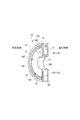
仕切板10は、図1および図3に示すように、高圧段101に対向する仕切高圧部11と、低圧段102に対向する仕切低圧部12とを有しており、車室3の内部に設置されている。仕切板10の上部は、車室3に備えられている収容部3Eに収容されている。
仕切板10は、車室3とは別体である。仕切高圧部11と仕切低圧部12とは、内周側で連結部13を介して連結されており、一体に構成されている。仕切板10は、断面略U字状に形成された円環状の部材である。
仕切高圧部11と仕切低圧部12との間には、軸線2Aの方向に間隙14が形成されている。
仕切板10の下端部10A(図1)は、車室3の内周部に支持されている。
仕切高圧部11と仕切低圧部12との間には、軸線2Aの方向に間隙14が形成されている。
仕切板10の下端部10A(図1)は、車室3の内周部に支持されている。
図3に、仕切板10の半分の部位に相当する半割体を示すように、仕切板10は一対の半割体から構成されている。一対の半割体を図1の紙面の手前側と背面側とから組み付けると、仕切板10の内端10Bにより形成される円形の開口に回転軸22が通される。仕切板10の内端10Bと回転軸22の外周部とは、ラビリンスシール10C(図1)を構成している。図3や図2ではラビリンスシール10Cの図示を省略している。
仕切板10よりも高圧段101側の蒸気は、後述するように、調圧弁30の複数の弁のうち開いている弁を通って仕切高圧部11と仕切低圧部12との間の間隙14に流入する。
間隙14は、図3および図2に示すように、仕切高圧部11と仕切低圧部12との間に設けられた隔壁14A~14Eにより、周方向に複数の部分141~145に区分されている。
隔壁14A~14Eにより区分されている部分141~145の各々の比率は、適宜に定めることができる。
間隙の部分141~145にはそれぞれ、低圧段102に通じるノズル15(噴口)が連通している。これらの部分141~145にはそれぞれ、少なくとも1つのノズル15が連通していればよい。
隔壁14A~14Eにより区分されている部分141~145の各々の比率は、適宜に定めることができる。
間隙の部分141~145にはそれぞれ、低圧段102に通じるノズル15(噴口)が連通している。これらの部分141~145にはそれぞれ、少なくとも1つのノズル15が連通していればよい。
ノズル15は、仕切低圧部12に、仕切低圧部12を厚み方向に貫通するように設けられ、ノズル15から低圧段102の最初の段に向けて蒸気が噴射される。
仕切高圧部11には、厚み方向に貫通する複数の貫通孔181が形成されている。図2では貫通孔181を黒い点で示している。これらの貫通孔181は、後述するように、高圧段101側と低圧段102側とを直接的に連通させるバイパス路18を構成している。
次に、図1および図2を参照し、調圧弁30について説明する。
調圧弁30は、高圧段101側からの蒸気を上方の位置Xにまで導く上り流路301(図1)と、位置Xに配置される複数の流量調整弁V1~V5(図2)と、流量調整弁V1~V5の各々に対応する複数の流路区画31~35(図2)と、調圧弁30の構成要素全体を収容するケーシング300(図1)とを有している。
ケーシング300は、車室3の外周部に締結されている。
調圧弁30は、高圧段101側からの蒸気を上方の位置Xにまで導く上り流路301(図1)と、位置Xに配置される複数の流量調整弁V1~V5(図2)と、流量調整弁V1~V5の各々に対応する複数の流路区画31~35(図2)と、調圧弁30の構成要素全体を収容するケーシング300(図1)とを有している。
ケーシング300は、車室3の外周部に締結されている。
図1に示すように、上り流路301は、高圧段101の最終段の近傍で、収容部3Eとケーシング300とに亘り立ち上がる壁301Aと、仕切高圧部11の上部およびそこから上方へと続く板301Bとの間に区画されている。上り流路301は、高圧段101を経た蒸気を、車室3内の上部より、仕切高圧部11の外端11Aを越え、外端11Aから仕切板10の径方向の外側に離れた位置Xに配置されている流量調整弁V1~V5(図2)まで導く。
上り流路301は、図2の紙面よりも手前に位置しており、上り流路301の上端またはその近傍が位置Xに相当する。
上り流路301は、図2の紙面よりも手前に位置しており、上り流路301の上端またはその近傍が位置Xに相当する。
流量調整弁V1~V5は、図2に示すように、位置Xで仕切板10の幅方向D1に並んでいる。流量調整弁V1~V5が並ぶ方向は、図1の紙面と直交する方向に相当する。
流量調整弁V1~V5はいずれも、弁体30Aと、弁体30Aを支持する弁棒30Bとを有している。図示しない駆動機構により弁棒30Bが進退されることで、弁体30Aと図示しない弁座との間の間隙の寸法が変わり、各流量調整弁V1~V5の開度が変わることとなる。
流量調整弁V1~V5はいずれも、弁体30Aと、弁体30Aを支持する弁棒30Bとを有している。図示しない駆動機構により弁棒30Bが進退されることで、弁体30Aと図示しない弁座との間の間隙の寸法が変わり、各流量調整弁V1~V5の開度が変わることとなる。
流路区画31~35は、流量調整弁V1~V5をそれぞれ通過した蒸気を低圧段102へと導く。図2に、流路区画31~35にそれぞれ対応する「1」~「5」までの番号を示している。
複数の流路区画31~35は、流量調整弁V1~V5の位置から仕切板10に向けて下方へと並列に延びている第1部分31A,32A,33A,34A,35Aと、上述したように仕切高圧部11と仕切低圧部12との間の間隙14が区分されてなる部分141~145(以下、第2部分)と、流路区画31~35毎に用意されている上述のノズル15とを含んで構成されている。
複数の流路区画31~35は、流量調整弁V1~V5の位置から仕切板10に向けて下方へと並列に延びている第1部分31A,32A,33A,34A,35Aと、上述したように仕切高圧部11と仕切低圧部12との間の間隙14が区分されてなる部分141~145(以下、第2部分)と、流路区画31~35毎に用意されている上述のノズル15とを含んで構成されている。
流路区画31~35は、全体として、仕切板10よりも外周側を含む領域において仕切板10の全周に亘り配置されている。
仕切板10の周囲の一部に何らかの部材等が配置されていることなどを理由として、流路区画31~35を全周に亘り配置することができない場合であっても、周方向の一部を除いて、仕切板10よりも外周側を含む領域において仕切板10の周方向の全体的に流路区画31~35を配置するものとする。
仕切板10の周囲の一部に何らかの部材等が配置されていることなどを理由として、流路区画31~35を全周に亘り配置することができない場合であっても、周方向の一部を除いて、仕切板10よりも外周側を含む領域において仕切板10の周方向の全体的に流路区画31~35を配置するものとする。
第1部分31A,32A,33A,34A,35Aは、上述した板301B(図1)とケーシング300の外壁との間が隔壁39A~39D(図2)により幅方向D1に複数に区分されてなる。
幅方向D1の中央に位置する流量調整弁V1に対応する第1部分31Aは、隔壁39Bと隔壁39Cとの間を間隙14に向けて下方へと延び、第2部分141に続いている。第1部分31Aと第2部分141とは、連続した流路を形成する。
図2において流量調整弁V1の隣の流量調整弁V2,V3にそれぞれ対応する第1部分32A,33Aも同様である。第1部分32Aは、第2部分142に連続し、第1部分33Aは、第2部分143に連続している。
幅方向D1の中央に位置する流量調整弁V1に対応する第1部分31Aは、隔壁39Bと隔壁39Cとの間を間隙14に向けて下方へと延び、第2部分141に続いている。第1部分31Aと第2部分141とは、連続した流路を形成する。
図2において流量調整弁V1の隣の流量調整弁V2,V3にそれぞれ対応する第1部分32A,33Aも同様である。第1部分32Aは、第2部分142に連続し、第1部分33Aは、第2部分143に連続している。
図2において左端に位置する流量調整弁V4に対応する第1部分34Aは、隔壁39Aとケーシング300の外壁との間と、仕切板10の間隙14よりも左側とに亘り形成され、第2部分144に連続している。
つまり、第1部分34Aおよび第2部分144からなる流路区画34は、隔壁39Aと、ケーシング300と、間隙14内の隔壁14Aと、ケーシング300の内部の下端に位置する隔壁39Eとによって区画されている。
つまり、第1部分34Aおよび第2部分144からなる流路区画34は、隔壁39Aと、ケーシング300と、間隙14内の隔壁14Aと、ケーシング300の内部の下端に位置する隔壁39Eとによって区画されている。
右端に位置する流量調整弁V5に対応する第1部分35Aは、隔壁39Dとケーシング300の外壁との間と、仕切板10の間隙14よりも右側とに亘り形成され、第2部分145に連続している。
上述のように第2部分141~145にそれぞれ設けられているノズル15(図3)を通じて、各流路区画31~35は低圧段102に個別に通じており、流量調整弁V1~V5のうち開いているものを通過した蒸気が、対応する流路区画31~35により低圧段102へと導入される。
例えば、流量調整弁V1を通過した蒸気が、第1部分31Aおよび第2部分141へと流入し、第2部分141からノズル15を通じて低圧段102へと導入される。流量調整弁V2~V5についても同様である。
例えば、流量調整弁V1を通過した蒸気が、第1部分31Aおよび第2部分141へと流入し、第2部分141からノズル15を通じて低圧段102へと導入される。流量調整弁V2~V5についても同様である。
複数の流量調整弁V1~V5の各々の開度は、制御装置5(図1)により弁棒30Bの駆動機構へと送られる指令に基づいて増減される。
制御装置5による制御により、流量調整弁V1~V5の各々の開度を個別に増減することで、調圧弁30全体として、低圧段102へと導入させる蒸気の流量を調整可能である。
例えば、流量調整弁V5を全開とし、流量調整弁V4を所定の開度で開き、残りの弁V1~V3を全閉としたり、流量調整弁V5,V4,V3,V2までを全開とし、流量調整弁V1を所定の開度で開いたりする。このように、流量調整弁V5,V4,V3,V2,V1をこの順序で使用し、各々の開度を調整することで、制御装置5は、必要な流量に応じて、流量調整弁V1~V5のいずれも全閉されているときの最小流量から、いずれも全開されているときの最大流量までに亘り、調圧弁30を通じて低圧段102へと導入される蒸気の流量を調整可能である。
制御装置5による制御により、流量調整弁V1~V5の各々の開度を個別に増減することで、調圧弁30全体として、低圧段102へと導入させる蒸気の流量を調整可能である。
例えば、流量調整弁V5を全開とし、流量調整弁V4を所定の開度で開き、残りの弁V1~V3を全閉としたり、流量調整弁V5,V4,V3,V2までを全開とし、流量調整弁V1を所定の開度で開いたりする。このように、流量調整弁V5,V4,V3,V2,V1をこの順序で使用し、各々の開度を調整することで、制御装置5は、必要な流量に応じて、流量調整弁V1~V5のいずれも全閉されているときの最小流量から、いずれも全開されているときの最大流量までに亘り、調圧弁30を通じて低圧段102へと導入される蒸気の流量を調整可能である。
上述した蒸気供給弁4(図1)も、調圧弁30と同様に、複数の流量調整弁と、周方向に区分された複数の流路区画とを含み、各流量調整弁の開度に応じて流量を調整可能に構成することができる。
ところで、蒸気タービン1の運転中、例えば、ポート3Cを通じて外部に取り出される抽気の流量を増大させる制御を行うため、調圧弁30の流量調整弁V1~V4を全閉して流量調整弁V5を全閉に近い開度に設定したり、あるいは、故障により調圧弁30の流量調整弁V1~V5が全閉の状態となって調圧弁30を通じた低圧段102への蒸気の導入が遮断される場合がある。このような場合、もし仮に、低圧段102を冷却する蒸気が導入されないか、あるいは、導入される蒸気が冷却に足りる所定量に対して不足する状態でロータ2が回転していると、低圧段102のブレード等が空気摩擦によりダメージを受けるおそれがある。
これを避けるため、調圧弁30の流路区画35に対応する流量調整弁V5にメカニカルストッパを設けることによって最低リフト量を設定し、常時、低圧段102を冷却するために必要な蒸気の流量を確保することが考えられる。しかし、冷却のため確保される分の蒸気は、流量調整弁V5を常時通過するのであるから、そもそも、調圧弁30を流れている必要がない。
これを避けるため、調圧弁30の流路区画35に対応する流量調整弁V5にメカニカルストッパを設けることによって最低リフト量を設定し、常時、低圧段102を冷却するために必要な蒸気の流量を確保することが考えられる。しかし、冷却のため確保される分の蒸気は、流量調整弁V5を常時通過するのであるから、そもそも、調圧弁30を流れている必要がない。
そこで、本実施形態は、仕切板10に、調圧弁30を経由しないで高圧段101側と低圧段102側とを連通させるバイパス路18(図1~図3)を備えることを主要な特徴としている。このバイパス路18は、常時開放されているので、ロータ2が回転しており蒸気供給弁4を通じて高圧段101に蒸気が供給されている間は常時、高圧段101側から調圧弁30を経由させないで低圧段102側へと蒸気を導入させる。
このバイパス路18があるため、調圧弁30には最低リフト量を設定するためのストッパを設ける必要がない。
このバイパス路18があるため、調圧弁30には最低リフト量を設定するためのストッパを設ける必要がない。
バイパス路18は、仕切高圧部11を厚み方向に貫通する貫通孔181(開口)と、貫通孔181が連通する間隙14およびノズル15(図2)とを含んで構成されている。貫通孔181は、仕切高圧部11の全周に亘り分布している。
これらの貫通孔181の各々の開口面積は、これらの貫通孔181を通じて低圧段102を冷却するために必要な蒸気の流量を考慮して、適宜に定めることができる。なお、図示された貫通孔181の分布は一例に過ぎず、複数の貫通孔181の各々の位置を適宜に定めることができる。
径が一定の貫通孔181を仕切高圧部11に形成することに代えて、ディヒューザ付き弁座を仕切高圧部11に設けることで、バイパス路18の開口を仕切高圧部11に備えることもできる。このディヒューザ付き弁座は、広い入口から受け入れた蒸気を一旦絞ったのち、出口に向け広げて低圧段側へと噴出する。
これらの貫通孔181の各々の開口面積は、これらの貫通孔181を通じて低圧段102を冷却するために必要な蒸気の流量を考慮して、適宜に定めることができる。なお、図示された貫通孔181の分布は一例に過ぎず、複数の貫通孔181の各々の位置を適宜に定めることができる。
径が一定の貫通孔181を仕切高圧部11に形成することに代えて、ディヒューザ付き弁座を仕切高圧部11に設けることで、バイパス路18の開口を仕切高圧部11に備えることもできる。このディヒューザ付き弁座は、広い入口から受け入れた蒸気を一旦絞ったのち、出口に向け広げて低圧段側へと噴出する。
本実施形態のように、貫通孔181の各々の位置をノズル15の位置よりも径方向内側に設定し、貫通孔181から噴出した蒸気がノズル15に直接掛からないようにすると、流量調整弁V1~V5を通じて第2部分141~145に入った蒸気を、そこからノズル15を通じてスムーズに流出させることができ、ノズル15への液滴の付着も防止できる。
なお、貫通孔181の各々の位置とノズル15の各々の位置とを仕切板10の径方向の同じ位置に設定しつつ、周方向にシフトさせることで、貫通孔181から噴出した蒸気がノズル15に直接掛からないようにすることもできる。
なお、貫通孔181の各々の位置とノズル15の各々の位置とを仕切板10の径方向の同じ位置に設定しつつ、周方向にシフトさせることで、貫通孔181から噴出した蒸気がノズル15に直接掛からないようにすることもできる。
仕切高圧部11に貫通孔181があいていると、高圧段101側から低圧段102側へと導入される蒸気の一部は、調圧弁30を経由することなく、貫通孔181に流入する。複数の貫通孔181にそれぞれ流入した蒸気は、第2部分141~145にそれぞれ連通するノズル15を通じて低圧段102へと導入される。
貫通孔181が全周に亘り分布していると、各貫通孔181から仕切板10の内部へと蒸気が周方向に均一に流入されるので、仕切板10に局所的な衝撃負荷が加えられるのを抑えることができる。
さらに、蒸気タービン1の運転起動時には、各貫通孔181を通じて均一な暖気が可能となる。
貫通孔181が全周に亘り分布していると、各貫通孔181から仕切板10の内部へと蒸気が周方向に均一に流入されるので、仕切板10に局所的な衝撃負荷が加えられるのを抑えることができる。
さらに、蒸気タービン1の運転起動時には、各貫通孔181を通じて均一な暖気が可能となる。
調圧弁30を経由することなくバイパス路18を通じて低圧段102に導入される蒸気は、高圧段101側から軸線2Aに沿って低圧段102側へと直接的に導入されるので、圧力損失が小さい。
図8および図9は、バイパス路18を備えずに、流量調整弁V5に最低リフト量を設定することで低圧段102への冷却蒸気を確保した例(比較例)を示している。この比較例では、仕切高圧部11に貫通孔181は無く、高圧段101から低圧段102へと導入される蒸気の全量が調圧弁30を通過する。
本実施形態(図1~図3)では、バイパス路18を通じて低圧段102に蒸気が導入される分だけ、比較例(図8および図9)と比べて調圧弁30を通る蒸気の流量が少ないので、蒸気が流通する調圧弁30の上り流路301の断面積や流路区画31~35の各々の流路断面積を比較例と比べて小さくすることができる。例えば、流路区画31~35の断面積を径方向(幅方向D1を含む)や軸線2Aの方向に小さくすることができる。また、流路の断面積が小さいことで、流量調整弁V1~V5も小さくすることができる。
本実施形態の調圧弁30の流路や弁体を内蔵するケーシング300の寸法は、比較例のケーシング300´の寸法と比べて、軸線2A方向にも径方向にも小さい。
本実施形態の調圧弁30の流路や弁体を内蔵するケーシング300の寸法は、比較例のケーシング300´の寸法と比べて、軸線2A方向にも径方向にも小さい。
本実施形態によれば、ケーシング300が軸線2A方向に短いことで、回転軸22の長さを短くしたり、もしくは、車室3内に段数増加のためのスペースを確保することができる。回転軸22の長さが短いと、剛性を確保しつつ回転軸22の径を小さくすることができるので、径方向へのサイズダウンを図り、ベアリング等のコストを抑えることもできる。
本実施形態によれば、仕切板10にバイパス路18が備えられていることにより、調圧弁30を通過する蒸気の流量が減少する分、調圧弁30の流路断面積を小さくでき、かつ、仕切板10よりも外周側の全周を使って調圧弁30の流路を設定することができるので、調圧弁30の流路を内蔵するケーシング300のサイズを抑えて、蒸気タービン1装置の小型化を図ることができる。
しかも、調圧弁30を通過する蒸気の流量が、低圧段102の冷却に必要な流量に対して不足していたり、故障により調圧弁30が全閉されたとしても、それとは関係なく、バイパス路18を通じて低圧段102側へと導入される蒸気により、低圧段102の冷却に必要な蒸気の所定流量を確保することができるので、蒸気タービン1の信頼性を向上させることができる。
しかも、調圧弁30を通過する蒸気の流量が、低圧段102の冷却に必要な流量に対して不足していたり、故障により調圧弁30が全閉されたとしても、それとは関係なく、バイパス路18を通じて低圧段102側へと導入される蒸気により、低圧段102の冷却に必要な蒸気の所定流量を確保することができるので、蒸気タービン1の信頼性を向上させることができる。
仕切板10のバイパス路18を通じた蒸気のバイパス流量は、蒸気タービン1の容量に応じて決められる。蒸気タービン1の容量の増加によりロータ2の回転数が増えると、低圧段102の冷却に必要な蒸気の流量も増える。もし仮に、比較例(図8および図9)のように仕切板10にバイパス路18を設けずに、流量調整弁V5に最低リフト量を設定しているとすれば、容量を増加すると、低圧段102へと導入される蒸気の全体流量において冷却蒸気の流量比率が増えるので、流量調整弁V5を全開したときの流量、あるいはそれ以上の流量が必要となる。このように、必要とされるバイパス流量が大きいほど、その流量分を仕切板10のバイパス路18が担うことによるサイズダウンの効果が大きい。
また、本実施形態の仕切板10を既存の蒸気タービンの仕切板に代えて車室3に設置することにより、蒸気タービンの容量を増大させることができる。このとき、特段、調圧弁30の制御を変更する必要はない。
既存の仕切板に代えて既存機に設置される仕切板10は、新規に製造された仕切板10であっても、既存機から取り外された仕切板にバイパス路18を設けてなる仕切板10であってもよい。バイパス路18の構成の一部として、調圧弁30の流路区画31~35を構成する第2部分141~145と、複数のノズル15とが利用されているので、第2部分141~145および複数のノズル15を有する既存の仕切板に、貫通孔181をあけるだけで、本実施形態の仕切板10を容易に得ることができる。
既存の仕切板に代えて既存機に設置される仕切板10は、新規に製造された仕切板10であっても、既存機から取り外された仕切板にバイパス路18を設けてなる仕切板10であってもよい。バイパス路18の構成の一部として、調圧弁30の流路区画31~35を構成する第2部分141~145と、複数のノズル15とが利用されているので、第2部分141~145および複数のノズル15を有する既存の仕切板に、貫通孔181をあけるだけで、本実施形態の仕切板10を容易に得ることができる。
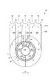
バイパス路18を構成する貫通孔は、必ずしも仕切板10の全周に分布している必要はない。図4に示すように仕切板10の周方向の少なくとも一部に貫通孔181が備えられていればよい。
本発明における仕切部は、上述したように車室3に設置される仕切板10の他、図5に示すように車室3と一体に成形される仕切部40として構成することもできる。
図5に示す仕切部40は、仕切板10と同様に、高圧段101の最終の段と低圧段102の最初の段との間を仕切っており、高圧段101側と低圧段102側とを連通させるバイパス路48を備えている。
仕切部40は、仕切板10と比べて厚肉に形成されており、上述の蒸気タービン1(図1)よりも高い圧力の蒸気で運転される蒸気タービン8に適合する。この蒸気タービン8にも、ポート3Cを通じた抽気または混気の圧力を調整する調圧弁30が備えられている。
図5に示す仕切部40は、仕切板10と同様に、高圧段101の最終の段と低圧段102の最初の段との間を仕切っており、高圧段101側と低圧段102側とを連通させるバイパス路48を備えている。
仕切部40は、仕切板10と比べて厚肉に形成されており、上述の蒸気タービン1(図1)よりも高い圧力の蒸気で運転される蒸気タービン8に適合する。この蒸気タービン8にも、ポート3Cを通じた抽気または混気の圧力を調整する調圧弁30が備えられている。
仕切部40は、仕切高圧部41と、仕切低圧部42と、これら仕切高圧部41および仕切低圧部42の間の間隙を区分する複数の隔壁44Aとを有している。仕切高圧部41、仕切低圧部42、および複数の隔壁44Aは、鋳造により車室3に一体に形成されている。
バイパス路48は、仕切高圧部41を貫通する複数の貫通孔と、周方向に区分されてなり、調圧弁30の流路区画の一部である第2部分141~145(図2参照)と、各流路区画毎に用意されたノズル15とを有している。このバイパス路48も、既設の仕切壁の仕切高圧部41に貫通孔をあけるだけで、容易に得ることができる。
上記実施形態と同様に、高圧段101側の蒸気が、バイパス路48を通じて低圧段102へと導入されることで、蒸気タービンの小型化を図ることができるとともに、たとえ故障等により調圧弁30を通じた冷却蒸気の導入が途絶えたとしても、冷却に最低限必要な流量の蒸気を低圧段102に確保することができる。
上記実施形態と同様に、高圧段101側の蒸気が、バイパス路48を通じて低圧段102へと導入されることで、蒸気タービンの小型化を図ることができるとともに、たとえ故障等により調圧弁30を通じた冷却蒸気の導入が途絶えたとしても、冷却に最低限必要な流量の蒸気を低圧段102に確保することができる。
上記以外にも、本発明の主旨を逸脱しない限り、上記実施形態で挙げた構成を取捨選択したり、他の構成に適宜変更することが可能である。
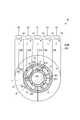
上述したバイパス路18(図2)やバイパス路48(図5)は、調圧弁30の流路の一部を含んで構成されているが、図6に示すバイパス路28や、図7に示すバイパス路38は、調圧弁30の流路の一部を含まずに構成されている。
上述したバイパス路18(図2)やバイパス路48(図5)は、調圧弁30の流路の一部を含んで構成されているが、図6に示すバイパス路28や、図7に示すバイパス路38は、調圧弁30の流路の一部を含まずに構成されている。
図6に示すバイパス路28は、仕切高圧部11と仕切低圧部12との間の間隙14の一部であるバイパス間隙17と、仕切高圧部11よりも高圧段101側とバイパス間隙17とを連通させる貫通孔281と、バイパス間隙17から低圧段102側へと通じるバイパス導入路282とを有している。仕切高圧部11の全周に亘り貫通孔281が分布している。
バイパス間隙17は、隔壁17Aにより仕切板10の内端10Bの周囲に区画されている環状の空間である。隔壁17Aよりも外周側に、調圧弁30の流路の一部である第2部分141~145が配置されている。
複数の貫通孔281、複数のバイパス導入路282、およびバイパス間隙17の全体がバイパス路28に相当する。
複数の貫通孔281、複数のバイパス導入路282、およびバイパス間隙17の全体がバイパス路28に相当する。
図7に示すバイパス路38は、仕切高圧部11と仕切低圧部12との間の間隙14の一部であるバイパス間隙19(格子の線で示す領域)と、仕切高圧部11よりも高圧段101側とバイパス間隙19とを連通させる貫通孔381と、バイパス間隙19から低圧段102側へと通じるバイパス導入路382とを有している。
バイパス間隙19は、隔壁19A,19Bにより間隙14の周方向の一部に区画されている空間である。
バイパス間隙19は、隔壁19A,19Bにより間隙14の周方向の一部に区画されている空間である。
図6に示すようなバイパス路28または図7に示すバイパス路38が仕切板10に備えられている場合も、上記実施形態と同様に、バイパス路28,38を通じて低圧段102へと導入される蒸気の流量だけ、調圧弁30を経由する蒸気の流量が減少するので、仕切板10よりも外周側を含む領域の全周に亘り流路が配置される調圧弁30を備えた蒸気タービンの小型化を図りながら、低圧段102の冷却に必要な蒸気の流量を確保することができる。
なお、バイパス路28またはバイパス路38を図5に示す仕切部40に適用することもできる。
なお、バイパス路28またはバイパス路38を図5に示す仕切部40に適用することもできる。
仕切高圧部よりも高圧段101側と間隙14とを連通させる開口は、仕切高圧部11を貫通する孔の形態に限らず、スリットや切欠であってもよい。
1,8 蒸気タービン
2 ロータ
2A 軸線
3 車室
3A 蒸気入口
3B 蒸気出口
3C ポート
3D 出口流路部
3E 収容部
4 蒸気供給弁
4A 入力ポート
5 制御装置(制御部)
7 遮断弁
10 仕切板(仕切部、仕切部材)
10A 下端部
10B 内端
10C ラビリンスシール
11 仕切高圧部
11A 外端
12 仕切低圧部
13 連結部
14 間隙
14A~14E 隔壁
15 ノズル
18 バイパス路
17,19 バイパス間隙
17A 隔壁
19A 隔壁
22 回転軸
23,24 ジャーナル軸受
25 スラスト軸受
28 バイパス路
30 調圧弁
30A 弁体
30B 弁棒
31~35 流路区画
31A,32A,33A,34A,35A 第1部分
38 バイパス路
39A~39E 隔壁
40 仕切部
41 仕切高圧部
42 仕切低圧部
44A 隔壁
48 バイパス路
101 高圧段
102 低圧段
141~145 第2部分
181 貫通孔(開口)
281 貫通孔(開口)
282 バイパス導入路
300 ケーシング
301 上り流路(流路)
301A 壁
301B 板
381 貫通孔(開口)
D1 幅方向
V1~V5 流量調整弁
X 位置
2 ロータ
2A 軸線
3 車室
3A 蒸気入口
3B 蒸気出口
3C ポート
3D 出口流路部
3E 収容部
4 蒸気供給弁
4A 入力ポート
5 制御装置(制御部)
7 遮断弁
10 仕切板(仕切部、仕切部材)
10A 下端部
10B 内端
10C ラビリンスシール
11 仕切高圧部
11A 外端
12 仕切低圧部
13 連結部
14 間隙
14A~14E 隔壁
15 ノズル
18 バイパス路
17,19 バイパス間隙
17A 隔壁
19A 隔壁
22 回転軸
23,24 ジャーナル軸受
25 スラスト軸受
28 バイパス路
30 調圧弁
30A 弁体
30B 弁棒
31~35 流路区画
31A,32A,33A,34A,35A 第1部分
38 バイパス路
39A~39E 隔壁
40 仕切部
41 仕切高圧部
42 仕切低圧部
44A 隔壁
48 バイパス路
101 高圧段
102 低圧段
141~145 第2部分
181 貫通孔(開口)
281 貫通孔(開口)
282 バイパス導入路
300 ケーシング
301 上り流路(流路)
301A 壁
301B 板
381 貫通孔(開口)
D1 幅方向
V1~V5 流量調整弁
X 位置
Claims (12)
- 蒸気が供給される高圧段と、前記高圧段を経た前記蒸気が導入される低圧段とを仕切る仕切部と、
前記高圧段を経た前記蒸気の一部である抽気の圧力、または前記高圧段を経た前記蒸気に外部から流入させる混気の圧力を調整可能な調圧弁と、を備え、
前記調圧弁は、
前記仕切部よりも外周側に位置し、前記仕切部よりも前記高圧段側から前記蒸気が導かれる複数の流量調整弁と、
前記複数の流量調整弁の各々に対応し、前記仕切部よりも前記低圧段側に噴口を介して連通する複数の流路区画と、を有し、
前記複数の流路区画は、全体として、前記仕切部よりも外周側を含む領域において前記仕切部の周方向の全体的に配置され、
前記仕切部には、前記調圧弁を経由しないで前記高圧段側と前記低圧段側とを連通させるバイパス路が備えられている、
ことを特徴とする蒸気タービン。 - 前記調圧弁は、
前記高圧段側からの前記蒸気を前記仕切部の外端から径方向の外側に離れた所定の位置にまで導く流路と、
前記所定の位置に配置される前記複数の流量調整弁と、
前記流量調整弁を通過した前記蒸気を前記低圧段に導く前記複数の流路区画と、を有し、
前記複数の流路区画は、
前記複数の流量調整弁の位置から前記仕切部に向けて並列に延びている第1部分と、
前記仕切部における前記高圧段に対向する前記仕切高圧部、および前記仕切部における前記低圧段に対向する前記仕切低圧部との間が前記周方向に区分されてなる第2部分と、
前記流路区画毎に用意されており、前記第2部分から前記低圧段側に通じる前記蒸気の噴口と、を含む、
請求項1に記載の蒸気タービン。 - 前記仕切部は、
前記高圧段および前記低圧段を収容する車室と一体に形成されているか、あるいは、前記車室とは別体の仕切部材であって、
前記高圧段に対向する仕切高圧部と、
前記低圧段に対向する仕切低圧部と、を有し、
前記バイパス路は、
前記仕切高圧部よりも前記高圧段側と、前記仕切高圧部および前記仕切低圧部の間に位置するバイパス間隙とを連通させる開口と、
前記バイパス間隙から前記低圧段側に通じる前記蒸気のバイパス導入路と、を含んで構成されている、
請求項1または2に記載の蒸気タービン。 - 前記仕切部は、
前記高圧段および前記低圧段を収容する車室と一体に形成されているか、あるいは、前記車室とは別体の仕切部材であって、
前記高圧段に対向する仕切高圧部と、
前記低圧段に対向する仕切低圧部と、を有し、
前記バイパス路は、
前記仕切高圧部よりも前記高圧段側と、前記仕切高圧部および前記仕切低圧部の間に位置する前記第2部分とを連通させる開口と、
前記第2部分から前記低圧段側に通じる前記噴口と、を含んで構成されている、
請求項2に記載の蒸気タービン。 - 前記仕切高圧部の全周もしくは一部に亘り、複数の前記開口が分布している、
請求項3または4に記載の蒸気タービン。 - 前記複数の流量調整弁の各々の開度を増減させる制御部を備え、
前記制御部は、
前記複数の流量調整弁のいずれも全閉されているときの最小流量から、前記複数の流量調整弁のいずれも全開されているときの最大流量までに亘り、前記調圧弁を通じて前記低圧段へと導入される前記蒸気の流量を調整可能である、
請求項1から5のいずれか一項に記載の蒸気タービン。 - 蒸気が供給される高圧段と、前記高圧段を経た前記蒸気が導入される低圧段とを仕切る仕切部材であって、
抽気または混気の圧力を調整可能な調圧弁が備えられる前記蒸気タービンに用いられ、
前記仕切部材よりも外周側を含む領域に配置される前記調圧弁を経由しないで前記高圧段側と前記低圧段側とを連通させるバイパス路が備えられている、
ことを特徴とする蒸気タービン用の仕切部材。 - 前記高圧段に対向する仕切高圧部と、
前記低圧段に対向する仕切低圧部と、を有し、
前記バイパス路は、
前記仕切高圧部よりも前記高圧段側と、前記仕切高圧部および前記仕切低圧部の間の間隙とを連通させる開口と、
前記間隙から前記低圧段側に通じる前記蒸気の噴口と、を含んで構成されている、
請求項7に記載の蒸気タービン用の仕切部材。 - 前記仕切高圧部の全周もしくは一部に亘り、複数の前記開口が分布している、
請求項8に記載の蒸気タービン用の仕切部材。 - 蒸気が供給される高圧段と、前記高圧段を経た前記蒸気が導入される低圧段とを仕切る仕切部と、前記高圧段を経た前記蒸気の一部である抽気の圧力を調整可能な調圧弁と、を備えた前記蒸気タービンの運転方法であって、
前記仕切部よりも外周側を含む領域に配置された前記調圧弁を通じて前記低圧段へと導入される前記蒸気の流量を調整することで前記抽気の圧力を制御し、
前記高圧段および前記低圧段が回転している間は常時、
前記仕切部に備えられたバイパス路を通じて、前記調圧弁を経由しないで前記高圧段側から前記低圧段側へと前記蒸気を導入させる、
ことを特徴とする蒸気タービンの運転方法。 - 蒸気が供給される高圧段と、前記高圧段を経た前記蒸気が導入される低圧段とを仕切る仕切部と、前記高圧段を経た前記蒸気に外部から流入させる混気の圧力を調整可能な調圧弁と、を備えた前記蒸気タービンの運転方法であって、
前記仕切部よりも外周側を含む領域に配置された前記調圧弁により前記低圧段へと導入される前記蒸気の流量を調整することで前記混気の圧力を制御し、
前記高圧段および前記低圧段が回転している間は常時、
前記仕切部に備えられたバイパス路を通じて、前記調圧弁を経由しないで前記高圧段側から前記低圧段側へと前記蒸気を導入させる、
ことを特徴とする蒸気タービンの運転方法。 - 前記調圧弁を通じて前記低圧段へと導入される前記蒸気の流量が、前記低圧段の冷却に必要な所定の流量に対して不足していたとしても、
前記バイパス路を通じて前記低圧段側へと導入される前記蒸気により、前記低圧段へと導入される前記蒸気の前記所定の流量を確保する、
請求項10または11に記載の蒸気タービンの運転方法。
Priority Applications (4)
| Application Number | Priority Date | Filing Date | Title |
|---|---|---|---|
| PCT/JP2017/004910 WO2018146792A1 (ja) | 2017-02-10 | 2017-02-10 | 蒸気タービン、仕切部材、および蒸気タービンの運転方法 |
| US16/477,085 US11333044B2 (en) | 2017-02-10 | 2017-02-10 | Steam turbine, partition member, and method for operating steam turbine |
| EP17895566.2A EP3553286B1 (en) | 2017-02-10 | 2017-02-10 | Steam turbine, partition member, and method for operating steam turbine |
| JP2018566719A JP6785885B2 (ja) | 2017-02-10 | 2017-02-10 | 蒸気タービン、仕切部材 |
Applications Claiming Priority (1)
| Application Number | Priority Date | Filing Date | Title |
|---|---|---|---|
| PCT/JP2017/004910 WO2018146792A1 (ja) | 2017-02-10 | 2017-02-10 | 蒸気タービン、仕切部材、および蒸気タービンの運転方法 |
Publications (1)
| Publication Number | Publication Date |
|---|---|
| WO2018146792A1 true WO2018146792A1 (ja) | 2018-08-16 |
Family
ID=63108266
Family Applications (1)
| Application Number | Title | Priority Date | Filing Date |
|---|---|---|---|
| PCT/JP2017/004910 Ceased WO2018146792A1 (ja) | 2017-02-10 | 2017-02-10 | 蒸気タービン、仕切部材、および蒸気タービンの運転方法 |
Country Status (4)
| Country | Link |
|---|---|
| US (1) | US11333044B2 (ja) |
| EP (1) | EP3553286B1 (ja) |
| JP (1) | JP6785885B2 (ja) |
| WO (1) | WO2018146792A1 (ja) |
Cited By (1)
| Publication number | Priority date | Publication date | Assignee | Title |
|---|---|---|---|---|
| CN114658497A (zh) * | 2022-03-01 | 2022-06-24 | 华电电力科学研究院有限公司 | 双抽背汽轮机抽汽系统投切前端控制系统及控制方法 |
Families Citing this family (2)
| Publication number | Priority date | Publication date | Assignee | Title |
|---|---|---|---|---|
| CN112145243B (zh) * | 2020-10-27 | 2024-03-26 | 中国船舶重工集团公司第七0四研究所 | 船用汽轮机集成式减压结构 |
| CN119957334B (zh) * | 2025-02-27 | 2025-10-17 | 中国船舶集团有限公司第七〇四研究所 | 一种船用汽轮机疏水系统 |
Citations (6)
| Publication number | Priority date | Publication date | Assignee | Title |
|---|---|---|---|---|
| FR598829A (fr) * | 1924-06-21 | 1925-12-26 | Oerlikon Maschf | Turbine à étages de pression pour dérivation intermédiaire de vapeur |
| JPS52107404A (en) * | 1976-03-05 | 1977-09-09 | Hitachi Ltd | Bleeding steam turbine |
| JPS55164708A (en) * | 1979-06-08 | 1980-12-22 | Hitachi Ltd | Steam control for mixed-pressure steam turbine and its steam controlling apparatus |
| DE4344070A1 (de) * | 1993-01-25 | 1994-07-28 | Abb Patent Gmbh | Dampfturbine mit einer Einrichtung zur Auskopplung eines Teiles des Dampfmassenstromes |
| JP2000018007A (ja) | 1998-07-03 | 2000-01-18 | Shin Nippon Machinery Co Ltd | 蒸気タービンの抽気制御弁 |
| JP2012177340A (ja) | 2011-02-25 | 2012-09-13 | Mitsubishi Heavy Industries Compressor Corp | 蒸気タービンの運転制御装置及び運転制御方法 |
Family Cites Families (5)
| Publication number | Priority date | Publication date | Assignee | Title |
|---|---|---|---|---|
| US2888240A (en) * | 1956-03-07 | 1959-05-26 | Allis Chalmers Mfg Co | Fluid cooled barrel cylinder for turbines |
| JPS6044481B2 (ja) * | 1978-08-28 | 1985-10-03 | 株式会社日立製作所 | 抽気タ−ビンの抽気部構造 |
| JPS5735106A (en) * | 1980-08-11 | 1982-02-25 | Toshiba Corp | Bleeder turbine |
| US5823742A (en) * | 1995-12-15 | 1998-10-20 | Dresser-Rand Company | Variable and bidirectional steam flow apparatus and method |
| SE509390C2 (sv) * | 1996-05-15 | 1999-01-18 | Abb Stal Ab | Ångturbin |
-
2017
- 2017-02-10 US US16/477,085 patent/US11333044B2/en active Active
- 2017-02-10 JP JP2018566719A patent/JP6785885B2/ja not_active Expired - Fee Related
- 2017-02-10 EP EP17895566.2A patent/EP3553286B1/en active Active
- 2017-02-10 WO PCT/JP2017/004910 patent/WO2018146792A1/ja not_active Ceased
Patent Citations (6)
| Publication number | Priority date | Publication date | Assignee | Title |
|---|---|---|---|---|
| FR598829A (fr) * | 1924-06-21 | 1925-12-26 | Oerlikon Maschf | Turbine à étages de pression pour dérivation intermédiaire de vapeur |
| JPS52107404A (en) * | 1976-03-05 | 1977-09-09 | Hitachi Ltd | Bleeding steam turbine |
| JPS55164708A (en) * | 1979-06-08 | 1980-12-22 | Hitachi Ltd | Steam control for mixed-pressure steam turbine and its steam controlling apparatus |
| DE4344070A1 (de) * | 1993-01-25 | 1994-07-28 | Abb Patent Gmbh | Dampfturbine mit einer Einrichtung zur Auskopplung eines Teiles des Dampfmassenstromes |
| JP2000018007A (ja) | 1998-07-03 | 2000-01-18 | Shin Nippon Machinery Co Ltd | 蒸気タービンの抽気制御弁 |
| JP2012177340A (ja) | 2011-02-25 | 2012-09-13 | Mitsubishi Heavy Industries Compressor Corp | 蒸気タービンの運転制御装置及び運転制御方法 |
Cited By (2)
| Publication number | Priority date | Publication date | Assignee | Title |
|---|---|---|---|---|
| CN114658497A (zh) * | 2022-03-01 | 2022-06-24 | 华电电力科学研究院有限公司 | 双抽背汽轮机抽汽系统投切前端控制系统及控制方法 |
| CN114658497B (zh) * | 2022-03-01 | 2023-08-29 | 华电电力科学研究院有限公司 | 双抽背汽轮机抽汽系统投切前端控制方法 |
Also Published As
| Publication number | Publication date |
|---|---|
| EP3553286A1 (en) | 2019-10-16 |
| JPWO2018146792A1 (ja) | 2019-11-07 |
| US11333044B2 (en) | 2022-05-17 |
| JP6785885B2 (ja) | 2020-11-18 |
| EP3553286B1 (en) | 2021-07-07 |
| US20190331004A1 (en) | 2019-10-31 |
| EP3553286A4 (en) | 2020-02-26 |
Similar Documents
| Publication | Publication Date | Title |
|---|---|---|
| WO2018146792A1 (ja) | 蒸気タービン、仕切部材、および蒸気タービンの運転方法 | |
| JP4767285B2 (ja) | 電気モータ冷却システム | |
| EP2990607A1 (en) | Cooling concept for turbine blades or vanes | |
| US11572802B2 (en) | Steam turbine having a steam supplementing structure and operating method therefor | |
| US10227898B2 (en) | Multi-valve steam valve and steam turbine | |
| KR20190015554A (ko) | 가스 터빈 및 가스 터빈의 운전 방법 | |
| JP2004146098A (ja) | 燃料電池システム | |
| JPH076520B2 (ja) | ガスタ−ビン機関の軸流圧縮機における径方向の羽根すきまを最善化するための装置 | |
| US11747219B2 (en) | Large-capacity hydrodynamic-type hydraulic dynamometer with output control mechanism | |
| JP2019523364A (ja) | 液体噴射式圧縮機又は膨張機要素、及び圧縮機又は膨張機装置の液体噴射を制御する方法 | |
| US9988927B2 (en) | Housing for a gas turbine, aircraft engine, and a process for operating a gas turbine | |
| JP5080864B2 (ja) | ガスタービンにおける冷却を最適化するための装置及び該装置を有するガスタービン | |
| US20090196732A1 (en) | Turbomachine, in Particular a Gas Turbine | |
| CA2794035A1 (en) | Axial compressor for fluid-flow machines | |
| US9200525B2 (en) | Turbomachine blade incidence control system and turbomachine | |
| CA2752305A1 (en) | Air-cooled motor-generator and method for operating such a motor-generator | |
| JP2013204545A (ja) | 圧縮機、及びガスタービン | |
| JP6295881B2 (ja) | 回転電機 | |
| US9500171B2 (en) | Pressure regulating valve | |
| JP6351191B2 (ja) | 緊急遮断装置及びこれを備える緊急遮断システム | |
| CN107849942B (zh) | 燃气轮机以及燃气轮机的运转方法 | |
| JP6201548B2 (ja) | 回転機械 | |
| WO2017145353A1 (ja) | 弁システム及び蒸気タービン | |
| JP2013057292A (ja) | ロータリバルブ | |
| BR112017011499B1 (pt) | Dispositivo e método para regular uma taxa de fluxo de massa de vapor em uma turbina a vapor |
Legal Events
| Date | Code | Title | Description |
|---|---|---|---|
| 121 | Ep: the epo has been informed by wipo that ep was designated in this application |
Ref document number: 17895566 Country of ref document: EP Kind code of ref document: A1 |
|
| ENP | Entry into the national phase |
Ref document number: 2018566719 Country of ref document: JP Kind code of ref document: A |
|
| ENP | Entry into the national phase |
Ref document number: 2017895566 Country of ref document: EP Effective date: 20190709 |
|
| NENP | Non-entry into the national phase |
Ref country code: DE |