WO2018147382A1 - リチウムイオン二次電池用正極合材およびその利用 - Google Patents
リチウムイオン二次電池用正極合材およびその利用 Download PDFInfo
- Publication number
- WO2018147382A1 WO2018147382A1 PCT/JP2018/004450 JP2018004450W WO2018147382A1 WO 2018147382 A1 WO2018147382 A1 WO 2018147382A1 JP 2018004450 W JP2018004450 W JP 2018004450W WO 2018147382 A1 WO2018147382 A1 WO 2018147382A1
- Authority
- WO
- WIPO (PCT)
- Prior art keywords
- positive electrode
- region
- ion secondary
- secondary battery
- lithium ion
- Prior art date
- Legal status (The legal status is an assumption and is not a legal conclusion. Google has not performed a legal analysis and makes no representation as to the accuracy of the status listed.)
- Ceased
Links
Images


Classifications
-
- H—ELECTRICITY
- H01—ELECTRIC ELEMENTS
- H01M—PROCESSES OR MEANS, e.g. BATTERIES, FOR THE DIRECT CONVERSION OF CHEMICAL ENERGY INTO ELECTRICAL ENERGY
- H01M4/00—Electrodes
- H01M4/02—Electrodes composed of, or comprising, active material
- H01M4/13—Electrodes for accumulators with non-aqueous electrolyte, e.g. for lithium-accumulators; Processes of manufacture thereof
- H01M4/131—Electrodes based on mixed oxides or hydroxides, or on mixtures of oxides or hydroxides, e.g. LiCoOx
-
- H—ELECTRICITY
- H01—ELECTRIC ELEMENTS
- H01M—PROCESSES OR MEANS, e.g. BATTERIES, FOR THE DIRECT CONVERSION OF CHEMICAL ENERGY INTO ELECTRICAL ENERGY
- H01M4/00—Electrodes
- H01M4/02—Electrodes composed of, or comprising, active material
- H01M4/36—Selection of substances as active materials, active masses, active liquids
- H01M4/48—Selection of substances as active materials, active masses, active liquids of inorganic oxides or hydroxides
- H01M4/52—Selection of substances as active materials, active masses, active liquids of inorganic oxides or hydroxides of nickel, cobalt or iron
- H01M4/525—Selection of substances as active materials, active masses, active liquids of inorganic oxides or hydroxides of nickel, cobalt or iron of mixed oxides or hydroxides containing iron, cobalt or nickel for inserting or intercalating light metals, e.g. LiNiO2, LiCoO2 or LiCoOxFy
-
- H—ELECTRICITY
- H01—ELECTRIC ELEMENTS
- H01M—PROCESSES OR MEANS, e.g. BATTERIES, FOR THE DIRECT CONVERSION OF CHEMICAL ENERGY INTO ELECTRICAL ENERGY
- H01M10/00—Secondary cells; Manufacture thereof
- H01M10/05—Accumulators with non-aqueous electrolyte
- H01M10/052—Li-accumulators
- H01M10/0525—Rocking-chair batteries, i.e. batteries with lithium insertion or intercalation in both electrodes; Lithium-ion batteries
-
- H—ELECTRICITY
- H01—ELECTRIC ELEMENTS
- H01M—PROCESSES OR MEANS, e.g. BATTERIES, FOR THE DIRECT CONVERSION OF CHEMICAL ENERGY INTO ELECTRICAL ENERGY
- H01M4/00—Electrodes
- H01M4/02—Electrodes composed of, or comprising, active material
- H01M4/13—Electrodes for accumulators with non-aqueous electrolyte, e.g. for lithium-accumulators; Processes of manufacture thereof
- H01M4/139—Processes of manufacture
- H01M4/1391—Processes of manufacture of electrodes based on mixed oxides or hydroxides, or on mixtures of oxides or hydroxides, e.g. LiCoOx
-
- H—ELECTRICITY
- H01—ELECTRIC ELEMENTS
- H01M—PROCESSES OR MEANS, e.g. BATTERIES, FOR THE DIRECT CONVERSION OF CHEMICAL ENERGY INTO ELECTRICAL ENERGY
- H01M4/00—Electrodes
- H01M4/02—Electrodes composed of, or comprising, active material
- H01M4/36—Selection of substances as active materials, active masses, active liquids
- H01M4/362—Composites
- H01M4/366—Composites as layered products
-
- H—ELECTRICITY
- H01—ELECTRIC ELEMENTS
- H01M—PROCESSES OR MEANS, e.g. BATTERIES, FOR THE DIRECT CONVERSION OF CHEMICAL ENERGY INTO ELECTRICAL ENERGY
- H01M4/00—Electrodes
- H01M4/02—Electrodes composed of, or comprising, active material
- H01M4/36—Selection of substances as active materials, active masses, active liquids
- H01M4/48—Selection of substances as active materials, active masses, active liquids of inorganic oxides or hydroxides
- H01M4/50—Selection of substances as active materials, active masses, active liquids of inorganic oxides or hydroxides of manganese
- H01M4/505—Selection of substances as active materials, active masses, active liquids of inorganic oxides or hydroxides of manganese of mixed oxides or hydroxides containing manganese for inserting or intercalating light metals, e.g. LiMn2O4 or LiMn2OxFy
-
- H—ELECTRICITY
- H01—ELECTRIC ELEMENTS
- H01M—PROCESSES OR MEANS, e.g. BATTERIES, FOR THE DIRECT CONVERSION OF CHEMICAL ENERGY INTO ELECTRICAL ENERGY
- H01M4/00—Electrodes
- H01M4/02—Electrodes composed of, or comprising, active material
- H01M4/62—Selection of inactive substances as ingredients for active masses, e.g. binders, fillers
- H01M4/624—Electric conductive fillers
-
- H—ELECTRICITY
- H01—ELECTRIC ELEMENTS
- H01M—PROCESSES OR MEANS, e.g. BATTERIES, FOR THE DIRECT CONVERSION OF CHEMICAL ENERGY INTO ELECTRICAL ENERGY
- H01M4/00—Electrodes
- H01M4/02—Electrodes composed of, or comprising, active material
- H01M2004/026—Electrodes composed of, or comprising, active material characterised by the polarity
- H01M2004/027—Negative electrodes
-
- H—ELECTRICITY
- H01—ELECTRIC ELEMENTS
- H01M—PROCESSES OR MEANS, e.g. BATTERIES, FOR THE DIRECT CONVERSION OF CHEMICAL ENERGY INTO ELECTRICAL ENERGY
- H01M4/00—Electrodes
- H01M4/02—Electrodes composed of, or comprising, active material
- H01M2004/026—Electrodes composed of, or comprising, active material characterised by the polarity
- H01M2004/028—Positive electrodes
-
- Y—GENERAL TAGGING OF NEW TECHNOLOGICAL DEVELOPMENTS; GENERAL TAGGING OF CROSS-SECTIONAL TECHNOLOGIES SPANNING OVER SEVERAL SECTIONS OF THE IPC; TECHNICAL SUBJECTS COVERED BY FORMER USPC CROSS-REFERENCE ART COLLECTIONS [XRACs] AND DIGESTS
- Y02—TECHNOLOGIES OR APPLICATIONS FOR MITIGATION OR ADAPTATION AGAINST CLIMATE CHANGE
- Y02E—REDUCTION OF GREENHOUSE GAS [GHG] EMISSIONS, RELATED TO ENERGY GENERATION, TRANSMISSION OR DISTRIBUTION
- Y02E60/00—Enabling technologies; Technologies with a potential or indirect contribution to GHG emissions mitigation
- Y02E60/10—Energy storage using batteries
Definitions
- the present invention relates to a positive electrode mixture for a lithium ion secondary battery used for a positive electrode of a lithium ion secondary battery, and a lithium ion secondary battery using the positive electrode mixture.
- Secondary batteries such as lithium ion secondary batteries and nickel metal hydride batteries have been preferably used in recent years as so-called portable power sources such as personal computers and portable terminals and vehicle power sources.
- a lithium ion secondary battery that is lightweight and obtains a high energy density is gaining importance as a high-output power source mounted on vehicles such as electric vehicles and hybrid vehicles.
- a positive electrode in which a positive electrode mixture layer is provided on the surface of a positive electrode current collector, which is a conductive foil body, is used.
- a positive electrode active material made of a lithium composite oxide that occludes and releases ions is included.
- Such a positive electrode mixture layer is formed of a paste-like positive electrode mixture for lithium ion secondary batteries (hereinafter, also simply referred to as “positive electrode mixture”) in which a positive electrode active material and other additives are dispersed in a dispersion medium. .
- Patent Document 1 discloses a cathode (positive electrode) in which a cathode active material composition (positive electrode mixture layer) is coated with vanadium oxide (conductive oxide).
- Patent Document 2 discloses a technique in which an oxide represented by a general formula: ABO 3 , A 2 BO 4 , or MO 2 or a mixture of these oxides is added to the positive electrode.
- Patent Document 3 discloses a non-aqueous electrolyte secondary battery in which the surface of active material particles contained in a positive electrode is coated with an oxide represented by general formulas: ABO 3 and A 2 BO 4. ing.
- Patent Documents 1 to 3 described above cannot be said to sufficiently reduce the electrical resistance of the positive electrode, and further improvements have been demanded.
- the surface of the positive electrode mixture layer is coated with a low-density and low-density granular vanadium oxide, and the vanadium oxide and the positive electrode active material are coated. It was found that a sufficient electron path could not be formed because the material was in point contact.
- a granular conductive oxide is dispersed in the positive electrode mixture layer. Similar to Patent Document 1 described above, the granular positive electrode active material, the conductive oxide, Was point contact.
- Patent Document 3 since the conductive oxide thin film is formed on the surface of the granular positive electrode active material, the granular conductive oxide as in Patent Document 1 and Patent Document 2 is used. A wider electronic path can be formed compared to the technology used.
- Patent Document 3 since the conductive oxide and the positive electrode active material are sintered and combined, the area of the contact portion between the positive electrode active material and the electrolyte is reduced. It has been found that a new problem arises that the reaction resistance increases due to a drastic decrease in.
- the present invention has been made in view of the above points, and its main purpose is to appropriately reduce the electric resistance of the positive electrode and to realize a high-performance lithium ion secondary battery. It is providing the positive electrode compound material for batteries.
- the present invention provides a positive electrode mixture for a lithium ion secondary battery having the following constitution.
- the positive electrode composite material for a lithium ion secondary battery disclosed herein is a positive electrode composite material used for a positive electrode of a lithium ion secondary battery, and is a granular material composed of a lithium composite oxide having a layered crystal structure containing at least lithium.
- a positive electrode active material and a conductive oxide are formed into a film shape.
- the average particle diameter based on the cross-sectional TEM observation of the primary particles in the granular area is 0.3 nm or more. In the cross-sectional TEM observation of the film-like area, the particle diameter is 0.3 nm or more. And no voids of 2 nm or more are observed.
- a granular region in which the primary particles of the conductive oxide are aggregated on at least a part of the surface of the granular positive electrode active material, and a film shape in which the conductive oxide is formed into a film shape The area is attached.
- the film-like region made of a conductive oxide is attached to the positive electrode active material in a very dense state where particles of 0.3 nm or more and voids of 2 nm or more are not recognized.
- a wide range of electron paths can be formed by contacting the surface of the active material on the surface, and the resistance at the positive electrode can be greatly reduced.
- the granular region of the positive electrode mixture is formed by aggregation of relatively large primary particles having an average particle diameter of 0.3 nm or more, the granular region on the surface of the positive electrode active material is attached. Then, since the primary particles and the positive electrode active material are in contact with each other at a point, an electron path is formed at such a contact, and the surface of the positive electrode active material is exposed at a portion other than the contact, Since a sufficient contact area with the electrolyte can be ensured, an increase in reaction resistance due to a decrease in the contact area between the positive electrode active material and the electrolyte can be suppressed.
- the resistance at the positive electrode can be greatly reduced by forming a wide electron path at the location where the film-like region made of the conductive oxide is attached.
- the contact area between the positive electrode active material and the electrolyte can be sufficiently secured at the part where the granular region is adhered, and the increase in reaction resistance can be suppressed, so that the battery performance compared to the conventional positive electrode mixture Can be greatly improved.
- the conductive oxide has the general formula (1): MO 2 (1) (Wherein M in the above formula (1) is one or more elements selected from transition metal elements of Group Va, Group VIa, Group VIIa, Group VIII and Group Ib) Metal oxide or general formula (2): ABO 3 (2) (However, A in the above formula (2) is one or more elements selected from the group consisting of a divalent typical element, a lanthanoid element, or a combination thereof, and B is a group IVa, Va It is a metal oxide having a perovskite structure represented by a transition metal element selected from Group, VIa, VIIa, VIII and Ib.
- the metal oxide represented by the general formula (1): MO 2 and the metal oxide having the perovskite structure represented by the general formula (2): ABO 3 have a suitable electron path with the positive electrode active material. Since it can form, the resistance in a positive electrode can be reduced more appropriately and battery performance can be improved more suitably.
- the conductive oxide is a ruthenium oxide or a lanthanum manganese cobalt composite oxide.
- a ruthenium oxide or lanthanum manganese cobalt composite oxide is constructed because the resistance at the positive electrode can be particularly suitably reduced among the metal oxides represented by the general formulas (1) and (2).
- the battery performance of the later lithium ion secondary battery can be improved more suitably.
- the positive electrode active material has the general formula (3): Li 1 + ⁇ Ni x Co y Mn z M ⁇ O 2- ⁇ A ⁇ (3)
- M in the above formula (3) is one selected from the group consisting of Zr, Mo, W, Mg, Ca, Na, Fe, Cr, Zn, Si, Sn, Al, and B, or Two or more elements
- a in formula (3) is one or more elements selected from the group consisting of F, Cl and Br, and x, y, z, ⁇ , ⁇ , ⁇ is 0 ⁇ ⁇ ⁇ 0.7, 0 ⁇ x ⁇ 0.9, 0 ⁇ y ⁇ 0.4, x + y + z ⁇ 1, 0 ⁇ ⁇ ⁇ 0.1, and 0 ⁇ ⁇ ⁇ 0.5, respectively.
- the lithium composite oxide represented by the general formula (3) can contribute to the construction of a battery having a high energy density because of its high ionic conductivity, and also has improved thermal
- the coverage based on the cross-sectional TEM observation of the conductive oxide on the surface of the positive electrode active material is 11% to 40%. If the coverage of the conductive oxide is too high, the contact area between the positive electrode active material and the electrolyte may be reduced. On the other hand, if the coverage is too low, a sufficient electron path may not be formed. This aspect is based on such knowledge, and by ensuring that the coverage of the conductive oxide on the surface of the positive electrode active material is 11% to 40%, a sufficient contact area between the positive electrode active material and the electrolyte is ensured. In addition, since the sufficient electronic path is formed, the battery performance can be improved more appropriately.
- the average particle diameter based on the cross-sectional TEM observation of the granular region is 0.6 nm to 55 nm
- the film thickness based on the cross-sectional TEM observation of the film-like region Is 0.5 nm to 50 nm.
- the positive electrode mixture disclosed herein in another preferred embodiment, at least a part of the granular region and the film-like region are in contact with each other. In this way, by bringing the granular region and the film-like region into contact with each other, a sufficient electron path can be formed at the contact portion, and a contact area between the positive electrode active material and the electrolyte is appropriately ensured. Therefore, the battery performance can be improved more suitably.
- a lithium ion secondary battery in which a positive electrode mixture layer is produced using the positive electrode mixture described above.
- a lithium ion secondary battery includes a positive electrode in which a positive electrode mixture layer is provided on a positive electrode current collector, and a negative electrode in which a negative electrode mixture layer is provided on a negative electrode current collector and non-water.
- a lithium ion secondary battery comprising an electrolyte, wherein the positive electrode mixture layer includes a granular positive electrode active material composed of a lithium composite oxide having a layered crystal structure containing at least lithium, and a conductive oxide. ing.
- the granular region in which the primary particles of the conductive oxide are aggregated and the conductive oxide are formed into a film shape on at least a part of the surface of the positive electrode active material is 0.3 nm or more, and in cross-sectional TEM observation of the film-like region, the particle size is 0.3 nm or more. No particles are observed, and voids of 2 nm or more are not recognized.
- the lithium ion secondary battery disclosed herein is a positive electrode mixture using the above positive electrode mixture in which a granular region made of a conductive oxide and a film-like region are attached to a part of the surface of the positive electrode active material. A layer is formed. For this reason, since the resistance in the positive electrode is appropriately reduced and the increase in reaction resistance in the positive electrode is suppressed, battery performance superior to that of the prior art can be exhibited.
- FIG. 1 is a cross-sectional TEM photograph of a positive electrode mixture according to this embodiment.
- the positive electrode mixture according to the present embodiment includes a positive electrode active material 1, a granular region 2a made of a conductive oxide, and a film region 2b. Each will be described in detail below.
- the positive electrode active material 1 in this embodiment is comprised from the lithium complex oxide which has a layered crystal structure containing at least lithium.
- the shape of the positive electrode active material 1 in this embodiment is granular, and FIG. 1 is a cross-sectional TEM photograph in which the vicinity of the surface of the granular positive electrode active material 1 is enlarged.
- the average particle diameter based on a cross-sectional TEM photograph of the granular positive electrode active material 1 is about 1 ⁇ m to 20 ⁇ m (preferably 2 ⁇ m to 10 ⁇ m).
- Examples of the lithium composite oxide constituting the positive electrode active material 1 include a lithium nickel composite oxide, a lithium nickel cobalt composite oxide, and a lithium nickel cobalt manganese composite oxide.
- the lithium composite oxide represented by the following general formula (3) is preferable. Since the lithium composite oxide represented by the following general formula (3) has high ionic conductivity, it can improve the energy density of the lithium ion secondary battery after construction and is also excellent in thermal stability. Therefore, durability can also be improved.
- M in the general formula (3) is one selected from the group consisting of Zr, Mo, W, Mg, Ca, Na, Fe, Cr, Zn, Si, Sn, Al, and B, or Two or more elements.
- a in general formula (3) is one or more elements selected from the group consisting of F, Cl, and Br, and x, y, z, ⁇ , ⁇ , and ⁇ are respectively 0 ⁇ ⁇ ⁇ 0.7, 0 ⁇ x ⁇ 0.9, 0 ⁇ y ⁇ 0.4, x + y + z ⁇ 1, 0 ⁇ ⁇ ⁇ 0.1, and 0 ⁇ ⁇ ⁇ 0.5.
- the positive electrode mixture according to this embodiment includes a conductive oxide.
- a metal oxide represented by the following general formula (1) is preferably used.
- M in the above general formula (1) is one or more elements selected from transition metal elements of Group Va, Group VIa, Group VIIa, Group VIII, and Group Ib.
- MO 2 examples include ruthenium dioxide (RuO 2 ), vanadium dioxide (VO 2 ), chromium dioxide (CrO 2 ), molybdenum dioxide (MoO 2 ), Tungsten dioxide (WO 2 ), rhenium dioxide (ReO 2 ), niobium dioxide (NbO 2 ), rhodium dioxide (RhO 2 ), iridium dioxide (IrO 2 ), palladium dioxide (PdO 2 ), platinum dioxide (PtO 2 ), dioxide dioxide Examples include osmium (OsO 2 ).
- a metal composite oxide having a perovskite structure represented by the following general formula (2) may be used as the conductive oxide.
- ABO 3 (2) is one or more elements selected from the group consisting of a divalent typical element, a lanthanoid element, or a combination thereof.
- B in the general formula (2) is one or more elements selected from transition metal elements of IVa group, Va group, VIa group, VIIa group, VIII group, and Ib group.
- ABO 3 examples include lanthanum manganese cobalt composite oxide (for example, LaMn 0.5 Co 0.5 O 3 ), lanthanum nickel composite oxide ( LaNiO 3) and vanadate strontium (SrVO 3), calcium vanadate (CaVO 3), ferrate strontium (SrFeO 3), lanthanum titanate (LaTiO 3), strontium chromate (SrCrO 3), calcium chromate (CaCrO 3 ), Calcium ruthenate (CaRuO 3 ), strontium ruthenate (SrRuO 3 ), strontium iridate (SrIrO 3 ), and the like.
- lanthanum manganese cobalt composite oxide for example, LaMn 0.5 Co 0.5 O 3
- LaNiO 3 lanthanum nickel composite oxide
- SrVO 3 vanadate strontium
- CaVO 3 calcium vanadate
- LaTiO 3
- a metal composite oxide having a composition other than that shown in the general formula (1) or the general formula (2) may be used as the conductive oxide.
- the metal composite oxide include lanthanum strontium nickel composite oxide (LaSrNiO 4 ).
- the metal oxide represented by the above general formula (1) or general formula (2) can appropriately form an electron path with the positive electrode active material, and can appropriately reduce the resistance at the positive electrode.
- ruthenium dioxide and lanthanum manganese cobalt composite oxide can particularly appropriately reduce the resistance in the positive electrode.
- the granular region 2a is formed by aggregation of the primary particles of the conductive oxide, and the average particle diameter based on the cross-sectional TEM observation of the primary particles is 0.3 nm or more, preferably 0.3 nm. It is ⁇ 15 nm, more preferably 1 nm to 10 nm.
- the granular region 2a constituted by the primary particles of the conductive oxide having a relatively large particle diameter is in contact with the surface of the positive electrode active material 1 at a point.
- an electron path can be formed at the contact point between the granular region 2a and the positive electrode active material 1, and the surface of the positive electrode active material 1 is exposed at a portion other than the contact point so that the positive electrode active material 1 and the electrolyte A wide contact area can be secured.
- the film-like region 2 b is a portion that appears in white in the cross-sectional TEM photograph shown in FIG. 1, and is a region where a conductive oxide is formed in a film shape so as to cover the surface of the positive electrode active material 1.
- the film-like region 2b in the present embodiment is different from a conductive oxide used in a general lithium ion secondary battery by a conductive oxide that has not been subjected to crystallization treatment such as firing. It is configured.
- the film-like region 2b has a very dense structure in which no primary particle of 0.3 nm or more exists and no void of 2 nm or more exists in the cross-sectional TEM observation. Since the film-like region 2b is in surface contact with the surface of the positive electrode active material 1 and has a dense structure in which large primary particles and voids do not exist, A wide electronic path can be formed.
- the granular region 2a and the film-like region 2b are mixed and attached to a part of the surface of the positive electrode active material 1, and therefore the film-like region 2b is attached.
- a wide electron path can be formed at the location where the positive electrode active material 1 is exposed and the surface of the positive electrode active material 1 is appropriately exposed at the location where the granular region 2a is adhered. A sufficient contact area can be secured. For this reason, by forming the positive electrode of the lithium ion secondary battery using the positive electrode mixture according to the present embodiment, a high performance lithium ion secondary battery with significantly improved battery performance can be obtained. .
- the positive electrode mixture according to the present embodiment when used, it becomes easy to desorb lithium ions from the electrolyte, so that the electrode reaction rate at the positive electrode is made faster than before to further improve battery performance. Can do. This is because the electron density is different between the granular region 2a and the film-like region 2b, and two kinds of conductive oxides having different electron densities are attached to the surface of the positive electrode active material, thereby providing a solvent supplied from the electrolyte. It is understood that this is because the activation energy in the desolvation process can be lowered by destabilizing the structure of lithium.
- the coverage based on the cross-sectional TEM observation of the conductive oxide on the surface of the positive electrode active material 1 is preferably 0.9% to 51%, and more preferably 11% to 40%.
- the average particle diameter of the granular region 2a and the film thickness of the film-like region 2b can greatly affect the battery performance.
- the average particle diameter based on the cross-sectional TEM observation of the granular region 2a is 0.3 nm to 60 nm (preferably 0.6 nm to 55 nm), and the film thickness is based on the cross-sectional TEM observation of the film-like region 2b.
- the area ratio of the film-like region 2b to the granular region 2a in the cross-sectional TEM observation is preferably 0.2% to 50%.
- 90% of primary particles constituting the granular region 2a are present in a region within 1.5 ⁇ m from the contact point between the granular region 2a and the positive electrode active material 1.
- an electron path between the granular region 2a and the positive electrode active material 1 can be more appropriately formed, so that the resistance at the positive electrode can be appropriately reduced.
- each region is formed such that at least a part of the granular region 2a and the film-like region 2b are in contact with each other.
- a sufficient electron path can be formed at the contact portion of these regions, and the contact area between the positive electrode active material and the electrolyte Therefore, the battery performance can be improved more suitably.
- a positive electrode active material can be manufactured through the same process as the positive electrode active material for common lithium ion secondary batteries. Specifically, an aqueous solution is prepared by weighing a metal element supply source (raw material) other than Li so as to obtain a desired composition ratio and mixing it with an aqueous solvent.
- a supply source of metal elements other than Li for example, sulfates of added metal elements such as Ni, Co, Mn (nickel sulfate: NiSO 4 , cobalt sulfate: CoSO 4 , manganese sulfate: MnSO 4, etc.) are used. obtain.
- the aqueous solution is neutralized by adding a basic aqueous solution (such as an aqueous sodium hydroxide solution) while stirring the prepared aqueous solution.
- a basic aqueous solution such as an aqueous sodium hydroxide solution
- the hydroxide of the additive metal element described above is deposited, and a sol-form raw material hydroxide (precursor) can be obtained.
- a lithium supply source lithium carbonate, lithium hydroxide, lithium nitrate, etc.
- a baking treatment is performed for 1 hour to 20 hours (for example, 15 hours).
- the fired body thus obtained is pulverized to a desired particle diameter (for example, an average particle diameter of 10 ⁇ m), whereby a granular positive electrode active material made of a lithium composite oxide having a layered crystal structure is obtained.
- the main metal element of the conductive oxide (M in the above general formula (1) or A, B in the general formula (2)) alkoxide (for example, ruthenium alkoxide) is used as the positive electrode active material.
- the mixture is stirred and dried at a predetermined temperature.
- the metal element alkoxide is decomposed, the metal element is oxidized to form a conductive oxide, and the film-shaped conductive oxide adheres to the surface of the positive electrode active material.
- a crystallization process such as baking is not performed after drying, a film-like region in which a conductive oxide is densely formed is attached to the surface of the positive electrode active material. be able to.
- the drying temperature in this step is preferably set to a temperature at which the conductive oxide does not crystallize, 200 ° C. to 450 ° C. (for example, 400 ° C.).
- region is made to adhere to the positive electrode active material which the film-like area
- the mechanochemical treatment is performed after mixing the powder of the positive electrode active material to which the film-like region is attached and the powder of the conductive oxide.
- the mechanochemical treatment temperature is room temperature (for example, 15 ° C. to 35 ° C.) and the load power is 0.1 kW to 1.0 kW ( For example, 0.5 kW) and the processing time is preferably set to 1 to 10 minutes (for example, 3 minutes).
- the positive electrode mixture according to the present embodiment is obtained by dispersing the composite material of the positive electrode active material and the conductive oxide obtained as described above in a predetermined dispersion medium. It can be prepared by appropriately adding other additives. In addition, about a dispersion medium and another additive, what is used for a general lithium ion secondary battery can be used without a restriction
- a lithium ion secondary battery in which a positive electrode is produced using the positive electrode mixture according to the above-described embodiment will be specifically described.
- a lithium ion secondary battery including a wound electrode body will be described as an example, but it is not intended to limit the use mode of the present invention.
- the positive electrode active material of the present invention can be used for a laminated electrode body in which a plurality of positive electrodes and negative electrodes are alternately laminated.
- FIG. 2 is a perspective view schematically showing the outer shape of the lithium ion secondary battery.
- the lithium ion secondary battery 100 is configured by accommodating an electrode body (not shown) in a rectangular case 50 shown in FIG.
- Case The case 50 includes a flat case main body 52 having an open upper end and a lid 54 that closes the opening at the upper end.
- the lid 54 is provided with a positive terminal 70 and a negative terminal 72.
- the positive electrode terminal 70 is electrically connected to the positive electrode of the electrode body in the case 50
- the negative electrode terminal 72 is electrically connected to the negative electrode.
- FIG. 3 is a perspective view schematically showing an electrode body of a lithium ion secondary battery.
- the electrode body in the present embodiment is a wound electrode body 80 produced by laminating and winding a long sheet-like positive electrode 10 and a negative electrode 20 together with a long sheet-like separator 40. It is.
- a positive Electrode In the positive electrode 10 in FIG. 3, a positive electrode mixture layer 14 containing a positive electrode active material is provided on both surfaces of a long sheet-like positive electrode current collector 12. A positive electrode mixture layer non-formation portion 16 that is not coated with the positive electrode mixture layer 14 is formed on one side edge in the width direction of the positive electrode 10, and the positive electrode mixture layer non-formation portion 16 is formed. Is electrically connected to the positive electrode terminal 70 (see FIG. 2).
- the positive electrode mixture layer 14 in the present embodiment is formed of the positive electrode mixture having the above-described configuration. Specifically, the positive electrode mixture layer 14 is formed by applying the positive electrode mixture according to the above-described embodiment to both surfaces of the positive electrode current collector 12 and drying it, followed by pressing at a predetermined pressure. In the positive electrode mixture layer 14, the granular region 2 a in which primary particles of the conductive oxide are aggregated and the conductive oxide are formed into a film shape on at least a part of the surface of the positive electrode active material 1 (see FIG. 1). The film-like region 2b is attached. By forming such a positive electrode mixture layer 14, the resistance in the positive electrode 10 can be reduced and the battery performance can be improved.
- the negative electrode 20 is provided with a negative electrode mixture layer 24 mainly composed of a negative electrode active material on both surfaces of a long sheet-like negative electrode current collector 22.
- a negative electrode mixture layer non-formed portion 26 is formed at one side edge in the width direction of the negative electrode 20, and the negative electrode mixture layer non-formed portion 26 is electrically connected to the negative electrode terminal 72 (see FIG. 1). It is connected.
- the material of the negative electrode active material is not particularly limited, and one kind of various materials that can be used as a negative electrode active material of a general lithium ion secondary battery is used alone, or two or more kinds are combined (mixed) Or, it can be used as a composite).
- Preferred examples of the negative electrode active material include carbon materials such as graphite (graphite), non-graphitizable carbon (hard carbon), graphitizable carbon (soft carbon), carbon nanotubes, or a combination of these. It is done. Among these, graphite materials (natural graphite (graphite), artificial graphite, etc.) can be preferably used from the viewpoint of energy density.
- the negative electrode active material is not limited to the above-described carbon-based material, and for example, lithium titanium composite oxide such as Li 4 Ti 5 O 12 and lithium composite oxide such as lithium transition metal composite nitride can be used.
- lithium titanium composite oxide such as Li 4 Ti 5 O 12
- lithium composite oxide such as lithium transition metal composite nitride
- various additives used for a general lithium ion secondary battery can be added to the negative electrode mixture layer 24 as necessary.
- the separator 40 is disposed so as to be interposed between the positive electrode 10 and the negative electrode 20 described above.
- a strip-shaped sheet material having a predetermined width and having a plurality of minute holes is used.
- the material of the separator 40 can be the same as that used for a general lithium ion secondary battery, and for example, a porous polyolefin resin or the like can be used.
- electrolyte As an electrolyte accommodated in case 50 with the above-mentioned winding electrode body 80, the thing similar to the electrolyte (for example, nonaqueous electrolyte) used for a general lithium ion secondary battery is specifically limited. It can be used without.
- a specific example of such a non-aqueous electrolyte LiPF 6 is mixed at about 1 mol / L in a mixed solvent of ethylene carbonate (EC), dimethyl carbonate (DMC), and ethyl methyl carbonate (EMC) (for example, volume ratio 3: 4: 3).
- EC ethylene carbonate
- DMC dimethyl carbonate
- EMC ethyl methyl carbonate
- the lithium ion secondary battery 100 constructed in this way since the electron path by the conductive oxide is sufficiently formed in the positive electrode mixture layer 14 of the positive electrode 10, the resistance in the positive electrode 10 is greatly reduced. In addition, since a sufficient contact area between the positive electrode active material and the electrolyte can be ensured, an increase in reaction resistance caused by coating the positive electrode active material with a conductive oxide can be appropriately suppressed. Furthermore, according to the lithium ion secondary battery 100, it is possible to easily desorb lithium ions from the electrolyte, and to increase the speed of the electrode reaction at the positive electrode as compared with the conventional case. Thus, according to the present embodiment, it is possible to provide a lithium ion secondary battery in which various battery performances are improved as compared with the conventional battery.
- test example Hereinafter, although the test example regarding this invention is demonstrated, description of a test example is not intending limiting this invention.
- Test A (1) Test Example 1 to Test Example 5 A positive electrode was produced using a different positive electrode mixture in each of Test Example 1 to Test Example 5, and a lithium ion secondary battery for evaluation test was constructed using the positive electrode.
- ruthenium dioxide (RuO 2 ) is used as the conductive oxide, and the granular region and the film-like region made of the RuO 2 are on the surface of the positive electrode active material.
- the adhering positive electrode mixture was used.
- the method of attaching the granular region and the film-like region to the surface of the positive electrode active material was performed according to the above-mentioned “attachment of conductive oxide”.
- the amount (mol) of the conductive oxide used in the film-like region is equal to the amount of the conductive oxide used in the granular region, and the total amount of Ru elements contained in the film-like region and the granular region is the same.
- the amount of conductive oxide used was adjusted so that the weight was 0.5 wt% of the positive electrode active material.
- Test Example 2 a positive electrode mixture in which only a film-like region made of RuO 2 was attached to the surface of the positive electrode active material was used.
- Test Example 3 a positive electrode mixture in which only a granular region made of RuO 2 was adhered to the surface of the positive electrode active material was used.
- Test Example 4 a positive electrode mixture to which no conductive oxide was added was used as a comparison target.
- the other conditions were set to the same conditions as in Test Example 1.
- Test Example 5 lanthanum manganese cobalt composite oxide (LaMn 0.5 Co 0.5 O 3 ) was used as the conductive oxide, and the granular region composed of LaMn 0.5 Co 0.5 O 3 A positive electrode mixture having a film-like region attached to the surface of the positive electrode active material was used.
- other conditions were set to the same conditions as Test Example 1.
- lithium nickel cobalt manganese composite oxide LiNi 0.33 Co 0.33 Mn 0.33 O 2
- the coverage of the conductive oxide was set to 11%.
- the positive electrode mixture is applied to both surfaces of the sheet-like positive electrode current collector (aluminum foil) using a die coater, dried, and then pressed at a predetermined pressure, whereby the positive electrode current collector is applied to the positive electrode current collector.
- a sheet-like positive electrode provided with a layer was produced.
- a negative electrode was produced using a natural graphite material (graphite) having an average particle diameter of 20 ⁇ m as a negative electrode active material.
- a negative electrode active material, a binder (SBR: styrene-butadiene copolymer), and a thickener (CMC) were mixed in a dispersion solvent (water) to prepare a paste-like negative electrode mixture.
- this negative electrode compound material was apply
- the mixing ratio of the negative electrode active material, SBR, and CMC in the negative electrode mixture was adjusted to 98: 1: 1.
- the electrolyte used was a non-aqueous electrolyte in which LiPF 6 as a supporting salt was contained at a concentration of about 1 mol / liter in a mixed solvent containing EC, DMC, and EMC at a volume ratio of 1: 1: 1. .
- a “normalized resistance value” was measured in order to evaluate the battery resistance of each test example. Specifically, first, the open circuit voltage of each evaluation test battery was adjusted to 3.70 V corresponding to 56% of SOC (State of Charge). And each battery was arrange
- Test Example 1 the normalized resistance value was significantly lower than in Test Examples 2-4. From this, the positive electrode active material and the conductive oxide are obtained by adhering both the granular region and the film-like region made of RuO 2 which is a conductive oxide represented by the general formula: MO 2 to the surface of the positive electrode active material. It was confirmed that a high-performance lithium ion secondary battery can be constructed by forming an appropriate electron path between the positive electrode active material and the electrode and ensuring a sufficient contact area between the positive electrode active material and the electrolyte.
- RuO 2 a conductive oxide represented by the general formula: MO 2
- Test B Next, as described above, when both the granular region and the film-like region made of a conductive oxide are attached to the surface of the positive electrode active material, the coverage of the conductive oxide on the surface of the positive electrode active material is the battery. Test B was conducted to examine the effect on performance. In Test B, as shown in Table 2 below, a lithium ion secondary battery (Test Example 6) constructed under the same conditions as Test Example 1 of Test A except that the coverage of the conductive oxide was varied. Normalized resistance values were measured for (9) to (9). In Table 2 below, the results of Test Example 1 and Test Example 4 in Test A are also shown as a comparative control.
- Test C in the positive electrode mixture in which both the granular region and the film-like region made of a conductive oxide are attached to the surface of the positive electrode active material, the average particle diameter of the conductive oxide and the film of the film-like region Test C was conducted to examine the effect of thickness on battery performance.
- the lithium ion 2 constructed under the same conditions as the test example 6 of the test B except that the average particle diameter of the granular region and the film thickness of the film-like region were made different. Normalized resistance values were measured for the secondary batteries (Test Examples 10 to 16).
- the lithium ion secondary battery provided by the technology disclosed herein exhibits excellent battery performance as described above, for example, it is suitable as a power source for a motor (electric motor) mounted on a vehicle such as an automobile. Can be used. Further, such lithium ion secondary batteries may be used in the form of an assembled battery formed by connecting a plurality of them in series and / or in parallel. Therefore, according to the technology disclosed herein, a vehicle including a lithium ion secondary battery or an assembled battery including a plurality of the batteries as a power source (typically, an automobile, particularly a hybrid automobile, an electric automobile, a fuel cell automobile, etc. A motor vehicle equipped with a simple electric motor) can be provided.
Landscapes
- Chemical & Material Sciences (AREA)
- Chemical Kinetics & Catalysis (AREA)
- Electrochemistry (AREA)
- General Chemical & Material Sciences (AREA)
- Engineering & Computer Science (AREA)
- Inorganic Chemistry (AREA)
- Materials Engineering (AREA)
- Manufacturing & Machinery (AREA)
- Composite Materials (AREA)
- Battery Electrode And Active Subsutance (AREA)
- Secondary Cells (AREA)
Abstract
正極における電気抵抗を適切に低減させて、高性能のリチウムイオン二次電池を実現することができるリチウムイオン二次電池用正極合材を提供する。かかる正極合材は、リチウムイオン二次電池の正極に用いられる正極合材であって、少なくともリチウムを含む層状の結晶構造を有するリチウム複合酸化物からなる粒状の正極活物質1と、導電性酸化物とを含み、ここで、正極活物質1の表面の少なくとも一部に、導電性酸化物の一次粒子が集合した粒状領域2aと、導電性酸化物が膜状に成形された膜状領域2bとが付着しており、粒状領域2aにおける一次粒子の断面TEM観察に基づいた平均粒子径が0.3nm以上であり、膜状領域2bの断面TEM観察において粒子径が0.3nm以上の粒子が認められず、かつ、2nm以上の空隙が認められない。
Description
本発明は、リチウムイオン二次電池の正極に用いられるリチウムイオン二次電池用正極合材、および該正極合材が用いられたリチウムイオン二次電池に関する。なお、本国際出願は2017年2月9日に出願された日本国特許出願2017-022417号に基づく優先権を主張しており、その出願の全内容は本明細書中に参照として組み入れられている。
リチウムイオン二次電池、ニッケル水素電池等の二次電池は、近年、パソコンや携帯端末等のいわゆるポータブル電源や車両駆動用電源として好ましく用いられている。特に、軽量で高エネルギー密度が得られるリチウムイオン二次電池は、電気自動車、ハイブリッド自動車等の車両に搭載される高出力電源として重要性が高まっている。
かかるリチウムイオン二次電池には、例えば、導電性を有する箔体である正極集電体の表面に正極合材層が付与された正極が用いられており、該正極合材層には、リチウムイオンを吸蔵・放出するリチウム複合酸化物からなる正極活物質が含まれている。かかる正極合材層は、正極活物質やその他の添加物を分散媒に分散させたペースト状のリチウムイオン二次電池用正極合材(以下、単に「正極合材」ともいう)によって形成される。
かかる正極合材に添加される添加物としては、例えば、導電性酸化物が挙げられる。当該導電性酸化物を添加することによって、正極活物質との間で電子パスを形成して正極における電気抵抗を低減させることができる。例えば、特許文献1には、カソード活物質組成物(正極合材層)がバナジウム酸化物(導電性酸化物)でコーティングされたカソード(正極)が開示されている。また、特許文献2には、一般式:ABO3、A2BO4、MO2で示される酸化物、または、これらの酸化物の混合物を正極に添加する技術が開示されている。また、特許文献3には、正極に含まれる活物質粒子の表面が、一般式:ABO3、A2BO4で表される酸化物により被覆されている非水電解液二次電池が開示されている。
しかしながら、上記した特許文献1~特許文献3に記載の技術では、正極における電気抵抗を十分に低減させることができるとは言えず、さらなる改良が求められていた。
例えば、本発明者が特許文献1に記載の技術を検討した結果、かかる技術では、低密度低密度の粒状バナジウム酸化物によって正極合材層の表面がコーティングされており、バナジウム酸化物と正極活物質とが点接触になっていたため、十分な電子パスを形成できていないことが分かった。
また、特許文献2に記載の技術においては、正極合材層内に粒状の導電性酸化物が分散しており、上記した特許文献1と同様に、粒状の正極活物質と導電性酸化物とが点接触となっていた。
例えば、本発明者が特許文献1に記載の技術を検討した結果、かかる技術では、低密度低密度の粒状バナジウム酸化物によって正極合材層の表面がコーティングされており、バナジウム酸化物と正極活物質とが点接触になっていたため、十分な電子パスを形成できていないことが分かった。
また、特許文献2に記載の技術においては、正極合材層内に粒状の導電性酸化物が分散しており、上記した特許文献1と同様に、粒状の正極活物質と導電性酸化物とが点接触となっていた。
一方、特許文献3に記載の技術においては、粒状の正極活物質の表面に導電性酸化物の薄膜を形成しているため、特許文献1や特許文献2のような粒状の導電性酸化物を使用する技術に比べて広範な電子パスを形成することができる。しかし、本発明者の検討によって、かかる特許文献3の技術では、上記した導電性酸化物と正極活物質とを焼結して複合化しているため、正極活物質と電解質との接触部分の面積が大幅に減少して反応抵抗が増加してしまうという新たな問題が生じることが分かった。
本発明は、かかる点に鑑みてなされたものであり、その主な目的は、正極における電気抵抗を適切に低減させて、高性能のリチウムイオン二次電池を実現することができるリチウムイオン二次電池用正極合材を提供することである。
上記目的を実現するべく、本発明によって以下の構成のリチウムイオン二次電池用正極合材が提供される。
ここで開示されるリチウムイオン二次電池用正極合材は、リチウムイオン二次電池の正極に用いられる正極合材であって、少なくともリチウムを含む層状の結晶構造を有するリチウム複合酸化物からなる粒状の正極活物質と、導電性酸化物とを含んでいる。
ここで、かかるリチウムイオン二次電池用正極合材では、正極活物質の表面の少なくとも一部に、導電性酸化物の一次粒子が集合した粒状領域と、導電性酸化物が膜状に成形された膜状領域とが付着しており、粒状領域における一次粒子の断面TEM観察に基づいた平均粒子径が0.3nm以上であり、膜状領域の断面TEM観察において、粒子径が0.3nm以上の粒子が認められず、かつ、2nm以上の空隙が認められない。
ここで、かかるリチウムイオン二次電池用正極合材では、正極活物質の表面の少なくとも一部に、導電性酸化物の一次粒子が集合した粒状領域と、導電性酸化物が膜状に成形された膜状領域とが付着しており、粒状領域における一次粒子の断面TEM観察に基づいた平均粒子径が0.3nm以上であり、膜状領域の断面TEM観察において、粒子径が0.3nm以上の粒子が認められず、かつ、2nm以上の空隙が認められない。
ここで開示される正極合材では、粒状の正極活物質の表面の少なくとも一部に、導電性酸化物の一次粒子が集合した粒状領域と、導電性酸化物が膜状に成形された膜状領域とが付着している。
かかる正極合材において、導電性酸化物からなる膜状領域は、0.3nm以上の粒子と2nm以上の空隙が認められないという非常に密な状態で正極活物質に付着しているため、正極活物質の表面に面で接触して広範な電子パスを形成し、正極における抵抗を大幅に低減させることができる。
一方、かかる正極合材の粒状領域は、平均粒子径が0.3nm以上という比較的に大きな一次粒子が集合することによって形成されているため、正極活物質表面における粒状領域が付着している箇所では、当該一次粒子と正極活物質とが点で接触しているため、かかる接点において電子パスが形成されているとともに、当該接点以外の部分において正極活物質の表面を露出させて正極活物質と電解質とが接触する面積を十分に確保することができるため、正極活物質と電解質との接触面積の低下による反応抵抗の増加を抑制することができる。
以上のように、ここで開示される正極合材によれば、導電性酸化物からなる膜状領域が付着している箇所において広範な電子パスを形成して正極における抵抗を大幅に低減させることができるとともに、粒状領域が付着している箇所において正極活物質と電解質との接触面積を十分に確保して反応抵抗の増加を抑制することができるため、従来の正極合材に比べて電池性能を大幅に向上させることができる。
かかる正極合材において、導電性酸化物からなる膜状領域は、0.3nm以上の粒子と2nm以上の空隙が認められないという非常に密な状態で正極活物質に付着しているため、正極活物質の表面に面で接触して広範な電子パスを形成し、正極における抵抗を大幅に低減させることができる。
一方、かかる正極合材の粒状領域は、平均粒子径が0.3nm以上という比較的に大きな一次粒子が集合することによって形成されているため、正極活物質表面における粒状領域が付着している箇所では、当該一次粒子と正極活物質とが点で接触しているため、かかる接点において電子パスが形成されているとともに、当該接点以外の部分において正極活物質の表面を露出させて正極活物質と電解質とが接触する面積を十分に確保することができるため、正極活物質と電解質との接触面積の低下による反応抵抗の増加を抑制することができる。
以上のように、ここで開示される正極合材によれば、導電性酸化物からなる膜状領域が付着している箇所において広範な電子パスを形成して正極における抵抗を大幅に低減させることができるとともに、粒状領域が付着している箇所において正極活物質と電解質との接触面積を十分に確保して反応抵抗の増加を抑制することができるため、従来の正極合材に比べて電池性能を大幅に向上させることができる。
また、ここで開示される正極合材の好ましい一つの態様では、導電性酸化物は、一般式(1):
MO2 (1)
(ただし、上記した式(1)中のMは、Va族、VIa族、VIIa族、VIII族およびIb族の遷移金属元素から選択される1種または2種以上の元素である)で示される金属酸化物、または、一般式(2):
ABO3 (2)
(ただし、上記した式(2)中のAは、2価の典型元素、ランタノイド元素またはこれらの組み合わせからなる群から選択される1種または2種以上の元素であり、BはIVa族、Va族、VIa族、VIIa族、VIII族およびIb族の遷移金属元素から選択される1種または2種以上の元素である)で示されるペロブスカイト構造を有する金属酸化物である。
上記した一般式(1):MO2で示される金属酸化物や、一般式(2):ABO3で示されるペロブスカイト構造を有する金属酸化物は、正極活物質との間で好適な電子パスを形成することができるため、正極における抵抗をより適切に低減させて電池性能をより好適に向上させることができる。
MO2 (1)
(ただし、上記した式(1)中のMは、Va族、VIa族、VIIa族、VIII族およびIb族の遷移金属元素から選択される1種または2種以上の元素である)で示される金属酸化物、または、一般式(2):
ABO3 (2)
(ただし、上記した式(2)中のAは、2価の典型元素、ランタノイド元素またはこれらの組み合わせからなる群から選択される1種または2種以上の元素であり、BはIVa族、Va族、VIa族、VIIa族、VIII族およびIb族の遷移金属元素から選択される1種または2種以上の元素である)で示されるペロブスカイト構造を有する金属酸化物である。
上記した一般式(1):MO2で示される金属酸化物や、一般式(2):ABO3で示されるペロブスカイト構造を有する金属酸化物は、正極活物質との間で好適な電子パスを形成することができるため、正極における抵抗をより適切に低減させて電池性能をより好適に向上させることができる。
また、ここで開示される正極合材の好ましい他の態様では、導電性酸化物が酸化物ルテニウムまたはランタンマンガンコバルト複合酸化物である。
かかる酸化物ルテニウムやランタンマンガンコバルト複合酸化物は、上記した一般式(1)や一般式(2)で示される金属酸化物の中でも、特に適切に正極における抵抗を低減させることができるため、構築後のリチウムイオン二次電池の電池性能をより好適に向上させることができる。
かかる酸化物ルテニウムやランタンマンガンコバルト複合酸化物は、上記した一般式(1)や一般式(2)で示される金属酸化物の中でも、特に適切に正極における抵抗を低減させることができるため、構築後のリチウムイオン二次電池の電池性能をより好適に向上させることができる。
また、ここで開示される正極合材の好ましい他の態様では、正極活物質は、一般式(3):
Li1+αNixCoyMnzMβO2-γAγ (3)
(ただし、上記した式(3)中のMは、Zr、Mo、W、Mg、Ca、Na、Fe、Cr、Zn、Si、Sn、Al、およびBからなる群から選択される1種または2種以上の元素であり、式(3)中のAは、F、Cl、Brからなる群から選択される1種または2種以上の元素であり、x、y、z、α、β、γは、それぞれ、0≦α≦0.7、0≦x<0.9、0≦y<0.4、x+y+z≒1、0≦β≦0.1、0≦γ≦0.5である)で示されるリチウム複合酸化物である。
かかる一般式(3)で示されるようなリチウム複合酸化物は、イオン伝導性が高いため高エネルギー密度の電池の構築に貢献し得るとともに、熱安定性にも優れているため電池耐久性の向上にも貢献することができる。
Li1+αNixCoyMnzMβO2-γAγ (3)
(ただし、上記した式(3)中のMは、Zr、Mo、W、Mg、Ca、Na、Fe、Cr、Zn、Si、Sn、Al、およびBからなる群から選択される1種または2種以上の元素であり、式(3)中のAは、F、Cl、Brからなる群から選択される1種または2種以上の元素であり、x、y、z、α、β、γは、それぞれ、0≦α≦0.7、0≦x<0.9、0≦y<0.4、x+y+z≒1、0≦β≦0.1、0≦γ≦0.5である)で示されるリチウム複合酸化物である。
かかる一般式(3)で示されるようなリチウム複合酸化物は、イオン伝導性が高いため高エネルギー密度の電池の構築に貢献し得るとともに、熱安定性にも優れているため電池耐久性の向上にも貢献することができる。
また、ここで開示される正極合材の好ましい他の態様では、正極活物質の表面における導電性酸化物の断面TEM観察に基づいた被覆率が11%~40%である。
導電性酸化物の被覆率が高すぎると正極活物質と電解質との接触面積が小さくなる虞がある一方で、低すぎると十分な電子パスを形成することができなくなる虞がある。本態様は、かかる知見に基づいたものであり、正極活物質の表面における導電性酸化物の被覆率を11%~40%にすることによって、正極活物質と電解質との接触面積を十分に確保するとともに、十分な電子パスを形成しているため、電池性能をより適切に向上させることができる。
導電性酸化物の被覆率が高すぎると正極活物質と電解質との接触面積が小さくなる虞がある一方で、低すぎると十分な電子パスを形成することができなくなる虞がある。本態様は、かかる知見に基づいたものであり、正極活物質の表面における導電性酸化物の被覆率を11%~40%にすることによって、正極活物質と電解質との接触面積を十分に確保するとともに、十分な電子パスを形成しているため、電池性能をより適切に向上させることができる。
また、ここで開示される正極合材の好ましい他の態様では、粒状領域の断面TEM観察に基づいた平均粒子径が0.6nm~55nmであり、膜状領域の断面TEM観察に基づいた膜厚が0.5nm~50nmである。
本発明者が種々の実験と検討を行った結果、ここで開示される正極合材では、粒状領域の平均粒子径と膜状領域の膜厚とがリチウムイオン二次電池の電池性能(規格化電池抵抗)に大きな影響を与えることが分かった。そして、更に実験を重ねた結果、粒状領域の平均粒子径を0.6nm~55nmとし、膜状領域の膜厚を0.5nm~50nmとすることによって、規格化電池抵抗が低い高性能なリチウムイオン二次電池を構築できることが分かった。本態様は、かかる知見に基づいてなされたものである。
本発明者が種々の実験と検討を行った結果、ここで開示される正極合材では、粒状領域の平均粒子径と膜状領域の膜厚とがリチウムイオン二次電池の電池性能(規格化電池抵抗)に大きな影響を与えることが分かった。そして、更に実験を重ねた結果、粒状領域の平均粒子径を0.6nm~55nmとし、膜状領域の膜厚を0.5nm~50nmとすることによって、規格化電池抵抗が低い高性能なリチウムイオン二次電池を構築できることが分かった。本態様は、かかる知見に基づいてなされたものである。
また、ここで開示される正極合材の好ましい他の態様では、粒状領域と膜状領域の少なくとも一部が相互に接触している。
このように、粒状領域と膜状領域とを相互に接触させることによって、該接触部分において、十分な電子パスを形成することができるとともに、正極活物質と電解質との接触面積を適切に確保することができるため、より好適に電池性能を向上させることができる。
このように、粒状領域と膜状領域とを相互に接触させることによって、該接触部分において、十分な電子パスを形成することができるとともに、正極活物質と電解質との接触面積を適切に確保することができるため、より好適に電池性能を向上させることができる。
また、本発明の他の一の側面として、上述した正極合材を用いて正極合材層を作製したリチウムイオン二次電池が提供される。具体的には、かかるリチウムイオン二次電池は、正極集電体上に正極合材層が付与されている正極と、負極集電体上に負極合材層が付与されている負極と非水電解質とを備えるリチウムイオン二次電池であって、正極合材層に、少なくともリチウムを含む層状の結晶構造を有するリチウム複合酸化物からなる粒状の正極活物質と、導電性酸化物とが含まれている。
そして、ここで開示されるリチウムイオン二次電池では、正極活物質の表面の少なくとも一部に、導電性酸化物の一次粒子が集合した粒状領域と、導電性酸化物が膜状に成形された膜状領域とが付着しており、粒状領域における一次粒子の断面TEM観察に基づいた平均粒子径が0.3nm以上であり、膜状領域の断面TEM観察において、粒子径が0.3nm以上の粒子が認められず、かつ、2nm以上の空隙が認められない。
ここで開示されるリチウムイオン二次電池は、正極活物質の表面の一部に導電性酸化物からなる粒状領域と膜状領域とが付着している上記の正極合材を用いて正極合材層が形成されている。このため、正極における抵抗が適切に低減されており、かつ、正極における反応抵抗の上昇が抑制されているため、従来よりも優れた電池性能を発揮することができる。
そして、ここで開示されるリチウムイオン二次電池では、正極活物質の表面の少なくとも一部に、導電性酸化物の一次粒子が集合した粒状領域と、導電性酸化物が膜状に成形された膜状領域とが付着しており、粒状領域における一次粒子の断面TEM観察に基づいた平均粒子径が0.3nm以上であり、膜状領域の断面TEM観察において、粒子径が0.3nm以上の粒子が認められず、かつ、2nm以上の空隙が認められない。
ここで開示されるリチウムイオン二次電池は、正極活物質の表面の一部に導電性酸化物からなる粒状領域と膜状領域とが付着している上記の正極合材を用いて正極合材層が形成されている。このため、正極における抵抗が適切に低減されており、かつ、正極における反応抵抗の上昇が抑制されているため、従来よりも優れた電池性能を発揮することができる。
以下、本発明の一実施形態について図面を参照しながら説明する。なお、以下の図面においては、同じ作用を奏する部材・部位には同じ符号を付して説明している。また、各図における寸法関係(長さ、幅、厚み等)は実際の寸法関係を反映するものではない。また、本明細書において特に言及している事項以外の事柄であって本発明の実施に必要な事柄(例えば、負極や電解質の構成および製法、リチウムイオン二次電池の構築に係る一般的技術等)は、当該分野における従来技術に基づく当業者の設計事項として把握され得る。
1.リチウムイオン二次電池用正極合材
図1は本実施形態に係る正極合材の断面TEM写真である。図1に示すように、本実施形態に係る正極合材には、正極活物質1と、導電性酸化物からなる粒状領域2aと膜状領域2bとが含まれている。以下、各々について具体的に説明する。
図1は本実施形態に係る正極合材の断面TEM写真である。図1に示すように、本実施形態に係る正極合材には、正極活物質1と、導電性酸化物からなる粒状領域2aと膜状領域2bとが含まれている。以下、各々について具体的に説明する。
(1)正極活物質
本実施形態における正極活物質1は、少なくともリチウムを含む層状の結晶構造を有するリチウム複合酸化物から構成されている。なお、本実施形態における正極活物質1の形状は粒状であり、図1は当該粒状の正極活物質1の表面近傍を拡大した断面TEM写真である。かかる粒状の正極活物質1の断面TEM写真に基づく平均粒子径は、1μm~20μm(好ましくは2μm~10μm)程度である。
本実施形態における正極活物質1は、少なくともリチウムを含む層状の結晶構造を有するリチウム複合酸化物から構成されている。なお、本実施形態における正極活物質1の形状は粒状であり、図1は当該粒状の正極活物質1の表面近傍を拡大した断面TEM写真である。かかる粒状の正極活物質1の断面TEM写真に基づく平均粒子径は、1μm~20μm(好ましくは2μm~10μm)程度である。
かかる正極活物質1を構成するリチウム複合酸化物としては、例えば、リチウムニッケル複合酸化物、リチウムニッケルコバルト複合酸化物、リチウムニッケルコバルトマンガン複合酸化物などが挙げられ、これらのリチウム複合酸化物の中でも、下記の一般式(3)で示されるリチウム複合酸化物が好ましい。下記の一般式(3)で示されるリチウム複合酸化物は、イオン伝導性が高いため、構築後のリチウムイオン二次電池のエネルギー密度を向上させることができるとともに、熱安定性にも優れているため耐久性を向上させることもできる。
Li1+αNixCoyMnzMβO2-γAγ (3)
なお、上記の一般式(3)中のMは、Zr、Mo、W、Mg、Ca、Na、Fe、Cr、Zn、Si、Sn、Al、およびBからなる群から選択される1種または2種以上の元素である。また、一般式(3)中のAは、F、Cl、Brからなる群から選択される1種または2種以上の元素であり、x、y、z、α、β、γは、それぞれ、0≦α≦0.7、0≦x<0.9、0≦y<0.4、x+y+z≒1、0≦β≦0.1、0≦γ≦0.5である。
Li1+αNixCoyMnzMβO2-γAγ (3)
なお、上記の一般式(3)中のMは、Zr、Mo、W、Mg、Ca、Na、Fe、Cr、Zn、Si、Sn、Al、およびBからなる群から選択される1種または2種以上の元素である。また、一般式(3)中のAは、F、Cl、Brからなる群から選択される1種または2種以上の元素であり、x、y、z、α、β、γは、それぞれ、0≦α≦0.7、0≦x<0.9、0≦y<0.4、x+y+z≒1、0≦β≦0.1、0≦γ≦0.5である。
(2)導電性酸化物
(a)導電性酸化物の組成
上記したように、本実施形態に係る正極合材には導電性酸化物が含まれている。本発明における導電性酸化物には、例えば、下記の一般式(1)で示されるような金属酸化物を用いることが好ましい。
MO2 (1)
なお、上記した一般式(1)中のMは、Va族、VIa族、VIIa族、VIII族およびIb族の遷移金属元素から選択される1種または2種以上の元素である。
上記した一般式(1):MO2で示される金属酸化物の具体例としては、二酸化ルテニウム(RuO2)、二酸化バナジウム(VO2)、二酸化クロム(CrO2)、二酸化モリブデン(MoO2)、二酸化タングステン(WO2)、二酸化レニウム(ReO2)、二酸化ニオブ(NbO2)、二酸化ロジウム(RhO2)、二酸化イリジウム(IrO2)、二酸化パラジウム(PdO2)、二酸化白金(PtO2)、二酸化オスミウム(OsO2)などが挙げられる。
(a)導電性酸化物の組成
上記したように、本実施形態に係る正極合材には導電性酸化物が含まれている。本発明における導電性酸化物には、例えば、下記の一般式(1)で示されるような金属酸化物を用いることが好ましい。
MO2 (1)
なお、上記した一般式(1)中のMは、Va族、VIa族、VIIa族、VIII族およびIb族の遷移金属元素から選択される1種または2種以上の元素である。
上記した一般式(1):MO2で示される金属酸化物の具体例としては、二酸化ルテニウム(RuO2)、二酸化バナジウム(VO2)、二酸化クロム(CrO2)、二酸化モリブデン(MoO2)、二酸化タングステン(WO2)、二酸化レニウム(ReO2)、二酸化ニオブ(NbO2)、二酸化ロジウム(RhO2)、二酸化イリジウム(IrO2)、二酸化パラジウム(PdO2)、二酸化白金(PtO2)、二酸化オスミウム(OsO2)などが挙げられる。
また、導電性酸化物には、上記した一般式(1)で示される金属酸化物の他に、下記の一般式(2)で示されるペロブスカイト構造の金属複合酸化物を用いてもよい。
ABO3 (2)
なお、上記した一般式(2)中のAは、2価の典型元素、ランタノイド元素またはこれらの組み合わせからなる群から選択される1種または2種以上の元素である。また、一般式(2)中のBはIVa族、Va族、VIa族、VIIa族、VIII族およびIb族の遷移金属元素から選択される1種または2種以上の元素である。
そして、かかる一般式(2):ABO3で示される金属複合酸化物としては、例えば、ランタンマンガンコバルト複合酸化物(例えば、LaMn0.5Co0.5O3)、ランタンニッケル複合酸化物(LaNiO3)やバナジン酸ストロンチウム(SrVO3)、バナジン酸カルシウム(CaVO3)、鉄酸ストロンチウム(SrFeO3)、チタン酸ランタン(LaTiO3)、クロム酸ストロンチウム(SrCrO3)、クロム酸カルシウム(CaCrO3)、ルテニウム酸カルシウム(CaRuO3)、ルテニウム酸ストロンチウム(SrRuO3)、イリジウム酸ストロンチウム(SrIrO3)などを用いることができる。
ABO3 (2)
なお、上記した一般式(2)中のAは、2価の典型元素、ランタノイド元素またはこれらの組み合わせからなる群から選択される1種または2種以上の元素である。また、一般式(2)中のBはIVa族、Va族、VIa族、VIIa族、VIII族およびIb族の遷移金属元素から選択される1種または2種以上の元素である。
そして、かかる一般式(2):ABO3で示される金属複合酸化物としては、例えば、ランタンマンガンコバルト複合酸化物(例えば、LaMn0.5Co0.5O3)、ランタンニッケル複合酸化物(LaNiO3)やバナジン酸ストロンチウム(SrVO3)、バナジン酸カルシウム(CaVO3)、鉄酸ストロンチウム(SrFeO3)、チタン酸ランタン(LaTiO3)、クロム酸ストロンチウム(SrCrO3)、クロム酸カルシウム(CaCrO3)、ルテニウム酸カルシウム(CaRuO3)、ルテニウム酸ストロンチウム(SrRuO3)、イリジウム酸ストロンチウム(SrIrO3)などを用いることができる。
また、導電性酸化物には、上記した一般式(1)や一般式(2)に示される以外の組成を有する金属複合酸化物を用いることもできる。かかる金属複合酸化物としては、例えば、ランタンストロンチウムニッケル複合酸化物(LaSrNiO4)が挙げられる。
上記した一般式(1)または一般式(2)で示される金属酸化物は、正極活物質との間で適切に電子パスを形成して、正極における抵抗を適切に低減することができる。なお、上記した具体例の中でも、二酸化ルテニウムやランタンマンガンコバルト複合酸化物は、特に適切に正極における抵抗を低減させることができる。
(b)導電性酸化物の構造
図1に示すように、本実施形態に係る正極合材では、正極活物質1の表面の少なくとも一部に、上記した導電性酸化物の一次粒子が集合した粒状領域2aと、当該導電性酸化物が膜状に成形された膜状領域2bとが付着している。
図1に示すように、本実施形態に係る正極合材では、正極活物質1の表面の少なくとも一部に、上記した導電性酸化物の一次粒子が集合した粒状領域2aと、当該導電性酸化物が膜状に成形された膜状領域2bとが付着している。
粒状領域2aは、上記したように、導電性酸化物の一次粒子が集合することによって形成されており、かかる一次粒子の断面TEM観察に基づく平均粒子径が0.3nm以上、好ましくは0.3nm~15nm、より好ましくは1nm~10nmである。このように比較的に大きな粒子径の導電性酸化物の一次粒子によって構成された粒状領域2aは、正極活物質1の表面に点で接触している。このため、粒状領域2aと正極活物質1との接点に電子パスを形成することができるとともに、当該接点以外の部分で正極活物質1の表面を露出させて、正極活物質1と電解質との接触面積を広く確保することができる。
膜状領域2bは、図1で示す断面TEM写真において白色で表れている部分であり、正極活物質1の表面を覆うように導電性酸化物が膜状に成形されている領域である。詳しくは後述するが、本実施形態における膜状領域2bは、一般的なリチウムイオン二次電池に用いられる導電性酸化物と異なり、焼成等の結晶化処理が施されていない導電性酸化物によって構成されている。そして、膜状領域2bは、断面TEM観察において、0.3nm以上の一次粒子が存在しておらず、かつ、2nm以上の空隙も存在していないという非常に密な構造を有している。かかる膜状領域2bは、正極活物質1の表面に面で接触しており、かつ、大きな一次粒子や空隙が存在していない密な構造を有しているため、正極活物質1との間で広範な電子パスを形成することができる。
このように、本実施形態に係る正極合材では、粒状領域2aと膜状領域2bとが混在して正極活物質1の表面の一部に付着しているため、膜状領域2bが付着している箇所で広範な電子パスを形成して正極における抵抗を大幅に低減させることができるとともに、粒状領域2aが付着している箇所で正極活物質1の表面を適度に露出させて電解質との接触面積を十分に確保することができる。このため、本実施形態に係る正極合材を用いてリチウムイオン二次電池の正極を形成することによって、従来よりも電池性能が大幅に向上した高性能のリチウムイオン二次電池を得ることができる。
さらに、本実施形態に係る正極合材を用いた場合、電解質からリチウムイオンを脱離させることが容易になるため、正極における電極反応の速度を従来よりも速くして電池性能をさらに向上させることができる。これは、粒状領域2aと膜状領域2bとでは電子密度が異なっており、該電子密度が異なる2種類の導電性酸化物を正極活物質の表面に付着させることによって、電解質から供給された溶媒和リチウムの構造を不安定にして脱溶媒和過程における活性化エネルギーを低くすることができるためであると解される。
なお、正極活物質1の表面における導電性酸化物の断面TEM観察に基づいた被覆率は、0.9%~51%であると好ましく、11%~40%であるとより好ましい。導電性酸化物の被覆率をこのように設定することによって、正極活物質と電解質との接触面積を十分に確保することができるとともに、十分な電子パスを形成することができるため、電池性能を適切に向上させることができる。
また、本発明者が本実施形態に係る正極合材について種々の実験と検討を行った結果、粒状領域2aの平均粒子径と膜状領域2bの膜厚が電池性能に大きな影響を与えることが分かった。具体的には、粒状領域2aの断面TEM観察に基づいた平均粒子径を0.3nm~60nm(好ましくは0.6nm~55nm)とし、かつ、膜状領域2bの断面TEM観察に基づいた膜厚を0.2nm~55nm(好ましくは0.5nm~50nm)とすることによって、規格化電池抵抗が大きく低減された高性能のリチウムイオン二次電池を構築することができる。
また、断面TEM観察における粒状領域2aに対する膜状領域2bの面積比率は、0.2%~50%であることが好ましい。このような比率で粒状領域2aと膜状領域2bとが存在している正極合材を用いることによって、正極における抵抗をより好適に低減させて高い電池性能を得ることができる。
また、粒状領域2aを構成する複数の一次粒子のうち90%の一次粒子が、粒状領域2aと正極活物質1との接点から1.5μm以内の領域に存在していることが好ましい。これによって、粒状領域2aと正極活物質1との電子パスをより適切に形成することができるため、正極における抵抗を適切に低減させることができる。
また、図1に示すように、粒状領域2aと膜状領域2bとの少なくとも一部が相互に接触するように各々の領域が形成されていることが好ましい。このように、粒状領域2aと膜状領域2bとを相互に接触させることによって、これらの領域の接触部分において、十分な電子パスを形成することができるとともに、正極活物質と電解質との接触面積を適切に確保することができるため、より好適に電池性能を向上させることができる。
2.リチウムイオン二次電池用正極合材の製造方法
次に、上記した本実施形態に係る正極合材の製造方法について説明する。
次に、上記した本実施形態に係る正極合材の製造方法について説明する。
(1)正極活物質の作製
正極活物質は、一般的なリチウムイオン二次電池用の正極活物質と同様の工程を経て作製することができる。具体的には、Li以外の金属元素の供給源(原料)を所望の組成比となるように秤量して水系溶媒と混合することによって水性溶液を調製する。このLi以外の金属元素の供給源としては、例えば、Ni、Co、Mnなどの添加金属元素の硫酸塩(硫酸ニッケル:NiSO4、硫酸コバルト:CoSO4、硫酸マンガン:MnSO4など)を使用し得る。
正極活物質は、一般的なリチウムイオン二次電池用の正極活物質と同様の工程を経て作製することができる。具体的には、Li以外の金属元素の供給源(原料)を所望の組成比となるように秤量して水系溶媒と混合することによって水性溶液を調製する。このLi以外の金属元素の供給源としては、例えば、Ni、Co、Mnなどの添加金属元素の硫酸塩(硫酸ニッケル:NiSO4、硫酸コバルト:CoSO4、硫酸マンガン:MnSO4など)を使用し得る。
次に、調製した水性溶液を撹拌しながら塩基性水溶液(水酸化ナトリウム水溶液など)を添加することによって当該水性溶液を中和する。これによって、上記した添加金属元素の水酸化物が析出してゾル状の原料水酸化物(前駆体)を得ることができる。
そして、得られたゾル状の前駆体にリチウム供給源(炭酸リチウム、水酸化リチウム、硝酸リチウムなど)を所定量混合した後、酸化性雰囲気の下で700℃~1000℃(例えば900℃)、1時間~20時間(例えば15時間)の焼成処理を行う。これによって得られた焼成体を、所望の粒子径(例えば平均粒子径10μm)に粉砕することにより、層状の結晶構造を有するリチウム複合酸化物からなる粒状の正極活物質が得られる。
そして、得られたゾル状の前駆体にリチウム供給源(炭酸リチウム、水酸化リチウム、硝酸リチウムなど)を所定量混合した後、酸化性雰囲気の下で700℃~1000℃(例えば900℃)、1時間~20時間(例えば15時間)の焼成処理を行う。これによって得られた焼成体を、所望の粒子径(例えば平均粒子径10μm)に粉砕することにより、層状の結晶構造を有するリチウム複合酸化物からなる粒状の正極活物質が得られる。
(2)導電性酸化物の付着
本実施形態に係る製造方法においては、上記のようにして得られた正極活物質の表面の少なくとも一部に、導電性酸化物の一次粒子が集合した粒状領域と、導電性酸化物が膜状に成形された膜状領域とを付着させる。
本実施形態に係る製造方法においては、上記のようにして得られた正極活物質の表面の少なくとも一部に、導電性酸化物の一次粒子が集合した粒状領域と、導電性酸化物が膜状に成形された膜状領域とを付着させる。
具体的には、導電性酸化物の主要金属元素(上記した一般式(1)中のM、または、一般式(2)中のA、B)のアルコキシド(例えば、ルテニウムアルコキシド)を正極活物質と混合し撹拌した後に所定の温度で乾燥させる。これによって、金属元素のアルコキシドが分解された後、当該金属元素が酸化されることによって導電性酸化物が形成され、膜状の導電性酸化物が正極活物質の表面に付着する。このとき、本実施形態においては、従来の技術と異なり、乾燥後に焼成等の結晶化処理を行わないため、導電性酸化物が密に形成された膜状領域を正極活物質の表面に付着させることができる。なお、本工程における乾燥温度は、導電性酸化物が結晶化しない温度、200℃~450℃(例えば400℃)に設定することが好ましい。
本実施形態においては、次に、膜状領域が表面に付着した正極活物質に、粒状領域を付着させる。具体的には、上記した膜状領域が付着した正極活物質の粉末と、導電性酸化物の粉末とを混合した後にメカノケミカル処理を実施する。一般なメカノヒュージョン装置(例えば、ホソカワミクロン社製:ノビルタミニ)を用いた場合には、かかるメカノケミカル処理の処理温度を常温(例えば15℃~35℃)、負荷電力を0.1kW~1.0kW(例えば0.5kW)、処理時間を1分~10分(例えば3分)に設定することが好ましい。
このように、膜状領域が付着した正極活物質の粉末と、導電性酸化物の粉末とを混合してメカノケミカル処理を施すことによって各々の粒子に機械的エネルギーが付与されるため、正極活物質の表面の少なくとも一部に、上記した膜状領域と、導電性酸化物の一次粒子が集合した粒状領域とを付着させることができる。
このように、膜状領域が付着した正極活物質の粉末と、導電性酸化物の粉末とを混合してメカノケミカル処理を施すことによって各々の粒子に機械的エネルギーが付与されるため、正極活物質の表面の少なくとも一部に、上記した膜状領域と、導電性酸化物の一次粒子が集合した粒状領域とを付着させることができる。
(3)正極合材の調製
そして、本実施形態に係る正極合材は、上記のようにして得られた正極活物質と導電性酸化物との複合材料を所定の分散媒に分散させた後に、その他の添加剤を適宜添加することによって作製することができる。なお、分散媒やその他の添加物については、一般的なリチウムイオン二次電池に用いられるものを特に制限なく用いることができ、本発明を特徴付けるものではないため、ここでは説明を省略する。
そして、本実施形態に係る正極合材は、上記のようにして得られた正極活物質と導電性酸化物との複合材料を所定の分散媒に分散させた後に、その他の添加剤を適宜添加することによって作製することができる。なお、分散媒やその他の添加物については、一般的なリチウムイオン二次電池に用いられるものを特に制限なく用いることができ、本発明を特徴付けるものではないため、ここでは説明を省略する。
3.リチウムイオン二次電池
次に、上記した実施形態に係る正極合材を用いて正極を作製したリチウムイオン二次電池について具体的に説明する。なお、以下では、捲回電極体を備えるリチウムイオン二次電池を例にして説明するが、本発明の使用態様を限定することを意図したものではない。例えば、本発明の正極活物質は、複数枚の正極と負極とを交互に積層させた積層電極体に使用することもできる。
次に、上記した実施形態に係る正極合材を用いて正極を作製したリチウムイオン二次電池について具体的に説明する。なお、以下では、捲回電極体を備えるリチウムイオン二次電池を例にして説明するが、本発明の使用態様を限定することを意図したものではない。例えば、本発明の正極活物質は、複数枚の正極と負極とを交互に積層させた積層電極体に使用することもできる。
図2はリチウムイオン二次電池の外形を模式的に示す斜視図である。このリチウムイオン二次電池100は、図2に示す角形のケース50の内部に電極体(図示省略)が収容されることにより構成されている。
(1)ケース
ケース50は、上端が開放された扁平なケース本体52と、その上端の開口部を塞ぐ蓋体54とから構成されている。蓋体54には、正極端子70および負極端子72が設けられている。図示は省略するが、正極端子70はケース50内の電極体の正極と電気的に接続されており、負極端子72は負極と電気的に接続されている。
ケース50は、上端が開放された扁平なケース本体52と、その上端の開口部を塞ぐ蓋体54とから構成されている。蓋体54には、正極端子70および負極端子72が設けられている。図示は省略するが、正極端子70はケース50内の電極体の正極と電気的に接続されており、負極端子72は負極と電気的に接続されている。
(2)電極体
次に、上記したケース50の内部に収容される電極体について説明する。図3はリチウムイオン二次電池の電極体を模式的に示す斜視図である。本実施形態における電極体は、図3に示すように、長尺シート状の正極10と負極20を長尺シート状のセパレータ40とともに積層して捲回することによって作製される捲回電極体80である。
次に、上記したケース50の内部に収容される電極体について説明する。図3はリチウムイオン二次電池の電極体を模式的に示す斜視図である。本実施形態における電極体は、図3に示すように、長尺シート状の正極10と負極20を長尺シート状のセパレータ40とともに積層して捲回することによって作製される捲回電極体80である。
(a)正極
図3における正極10では、長尺シート状の正極集電体12の両面に、正極活物質を含む正極合材層14が付与されている。そして、正極10の幅方向の一方の側縁部には、正極合材層14が塗工されていない正極合材層非形成部16が形成されており、この正極合材層非形成部16が上記した正極端子70(図2参照)と電気的に接続される。
図3における正極10では、長尺シート状の正極集電体12の両面に、正極活物質を含む正極合材層14が付与されている。そして、正極10の幅方向の一方の側縁部には、正極合材層14が塗工されていない正極合材層非形成部16が形成されており、この正極合材層非形成部16が上記した正極端子70(図2参照)と電気的に接続される。
本実施形態における正極合材層14は、上記した構成の正極合材によって形成されている。具体的には、上記した実施形態に係る正極合材を正極集電体12の両面に塗布して乾燥させた後に、所定の圧力でプレスすることによって正極合材層14が形成される。
かかる正極合材層14では、正極活物質1(図1参照)の表面の少なくとも一部に、導電性酸化物の一次粒子が集合した粒状領域2aと、導電性酸化物が膜状に成形された膜状領域2bとが付着している。このような正極合材層14を形成することによって、正極10における抵抗を低減させて電池性能を向上させることができる。
かかる正極合材層14では、正極活物質1(図1参照)の表面の少なくとも一部に、導電性酸化物の一次粒子が集合した粒状領域2aと、導電性酸化物が膜状に成形された膜状領域2bとが付着している。このような正極合材層14を形成することによって、正極10における抵抗を低減させて電池性能を向上させることができる。
(b)負極
負極20についても、正極10と同様に、長尺シート状の負極集電体22の両面に負極活物質を主成分とする負極合材層24が付与されている。そして、負極20の幅方向の一方の側縁部に負極合材層非形成部26が形成されており、この負極合材層非形成部26が負極端子72(図1参照)と電気的に接続されている。
負極20についても、正極10と同様に、長尺シート状の負極集電体22の両面に負極活物質を主成分とする負極合材層24が付与されている。そして、負極20の幅方向の一方の側縁部に負極合材層非形成部26が形成されており、この負極合材層非形成部26が負極端子72(図1参照)と電気的に接続されている。
本実施形態において負極活物質の材料は、特に制限されず、一般的なリチウムイオン二次電池の負極活物質として使用し得る各種の材料の1種を単独で、または2種以上を組み合わせる(混合または複合体化する)等して用いることができる。かかる負極活物質の好適例として、黒鉛(グラファイト)、難黒鉛化炭素(ハードカーボン)、易黒鉛化炭素(ソフトカーボン)、カーボンナノチューブ、或いはこれらを組み合わせた構造を有するもの等の炭素材料が挙げられる。エネルギー密度の観点から、これらの中でも黒鉛系材料(天然黒鉛(石墨)や人造黒鉛等)を好ましく用いることができる。
また、負極活物質は、上記した炭素系材料に限定されず、例えば、Li4Ti5O12等のリチウムチタン複合酸化物、リチウム遷移金属複合窒化物等のリチウム複合酸化物を用いることもできる。また、負極合材層24についても、正極合材層14と同様に、一般的なリチウムイオン二次電池に用いられる各種添加剤を必要に応じて添加することができる。
また、負極活物質は、上記した炭素系材料に限定されず、例えば、Li4Ti5O12等のリチウムチタン複合酸化物、リチウム遷移金属複合窒化物等のリチウム複合酸化物を用いることもできる。また、負極合材層24についても、正極合材層14と同様に、一般的なリチウムイオン二次電池に用いられる各種添加剤を必要に応じて添加することができる。
(c)セパレータ
セパレータ40は、上記した正極10と負極20との間に介在するように配置されている。このセパレータ40には、微小な孔を複数有する所定幅の帯状のシート材が用いられる。セパレータ40の材料は、一般的なリチウムイオン二次電池に用いられるものと同様のものを用いることができ、例えば、多孔質ポリオレフィン系樹脂等を用いることができる。
セパレータ40は、上記した正極10と負極20との間に介在するように配置されている。このセパレータ40には、微小な孔を複数有する所定幅の帯状のシート材が用いられる。セパレータ40の材料は、一般的なリチウムイオン二次電池に用いられるものと同様のものを用いることができ、例えば、多孔質ポリオレフィン系樹脂等を用いることができる。
(4)電解質
また、上記した捲回電極体80とともにケース50に収納される電解質としては、一般的なリチウムイオン二次電池に用いられる電解質と同様のもの(例えば非水電解液)を特に限定なく使用することができる。かかる非水電解液の具体例としては、エチレンカーボネート(EC)とジメチルカーボネート(DMC)とエチルメチルカーボネート(EMC)との混合溶媒(例えば体積比3:4:3)にLiPF6を約1mol/Lの濃度で含有させたものが挙げられる。
また、上記した捲回電極体80とともにケース50に収納される電解質としては、一般的なリチウムイオン二次電池に用いられる電解質と同様のもの(例えば非水電解液)を特に限定なく使用することができる。かかる非水電解液の具体例としては、エチレンカーボネート(EC)とジメチルカーボネート(DMC)とエチルメチルカーボネート(EMC)との混合溶媒(例えば体積比3:4:3)にLiPF6を約1mol/Lの濃度で含有させたものが挙げられる。
4.リチウムイオン二次電池の構築
上記した各部材を備えたリチウムイオン二次電池を構築するに際しては、先ず、ケース本体52の内部に捲回電極体80を収容するとともに、電解質をケース本体52内に充填(注液)する。その後、蓋体54に設けられた各々の電極端子70、72を、捲回電極体80の正極合材層非形成部16と負極合材層非形成部26に接続した後、蓋体54でケース本体52上端の開口部を封止する。これによってリチウムイオン二次電池100が構築される。
上記した各部材を備えたリチウムイオン二次電池を構築するに際しては、先ず、ケース本体52の内部に捲回電極体80を収容するとともに、電解質をケース本体52内に充填(注液)する。その後、蓋体54に設けられた各々の電極端子70、72を、捲回電極体80の正極合材層非形成部16と負極合材層非形成部26に接続した後、蓋体54でケース本体52上端の開口部を封止する。これによってリチウムイオン二次電池100が構築される。
このようにして構築されたリチウムイオン二次電池100では、正極10の正極合材層14において、導電性酸化物による電子パスが十分に形成されているため、正極10における抵抗を大幅に低減させることができるとともに、正極活物質と電解質との接触面積を十分に確保することもできるため、導電性酸化物で正極活物質を被覆することによる反応抵抗の上昇を適切に抑制することができる。さらに、かかるリチウムイオン二次電池100によれば、電解質からリチウムイオンを脱離させることを容易にして正極における電極反応の速度を従来よりも速くすることができる。このように、本実施形態によれば、種々の電池性能が従来よりも向上したリチウムイオン二次電池を提供することができる。
[試験例]
以下、本発明に関する試験例を説明するが、試験例の説明は本発明を限定することを意図したものではない。
以下、本発明に関する試験例を説明するが、試験例の説明は本発明を限定することを意図したものではない。
本試験例では、正極活物質の表面の一部に導電性酸化物からなる粒状領域と膜状領域とを付着させた正極合材を用いてリチウムイオン二次電池を構築した場合に、電池性能にどのような影響が生じるかを調べるために以下の試験A~試験Cを行った。
1.試験A
(1)試験例1~試験例5
試験例1~試験例5の各々で異なる正極合材を用いて正極を作製し、当該正極を用いて評価試験用のリチウムイオン二次電池を構築した。
(1)試験例1~試験例5
試験例1~試験例5の各々で異なる正極合材を用いて正極を作製し、当該正極を用いて評価試験用のリチウムイオン二次電池を構築した。
具体的には、表1に示すように、試験例1では、導電性酸化物として二酸化ルテニウム(RuO2)を使用し、当該RuO2からなる粒状領域と膜状領域が正極活物質の表面に付着している正極合材を使用した。なお、粒状領域と膜状領域を正極活物質の表面に付着させる方法は上記した「導電性酸化物の付着」に従って行った。このとき、膜状領域に使用した導電性酸化物の量(mol)と、粒状領域に使用した導電性酸化物の量を等量とし、かかる膜状領域と粒状領域に含まれるRu元素の総重量が正極活物質の0.5wt%になるように導電性酸化物の使用量を調整した。
また、試験例2ではRuO2からなる膜状領域のみが正極活物質の表面に付着している正極合材を使用した。また、試験例3ではRuO2からなる粒状領域のみが正極活物質の表面に付着している正極合材を使用した。そして、試験例4では比較対象として、導電性酸化物が添加されていない正極合材を使用した。なお、試験例2~4について、他の条件は試験例1と同じ条件に設定した。
さらに、試験例5では、導電性酸化物としてランタンマンガンコバルト複合酸化物(LaMn0.5Co0.5O3)を使用し、当該LaMn0.5Co0.5O3からなる粒状領域と膜状領域を正極活物質の表面に付着している正極合材を使用した。なお、試験例5についても他の条件は試験例1と同じ条件に設定した
なお、試験例1~試験例5では、正極活物質としてリチウムニッケルコバルトマンガン複合酸化物(LiNi0.33Co0.33Mn0.33O2)を用いた。また、試験例1~試験例3および試験例5では導電性酸化物の被覆率を11%に設定した。
(2)評価試験用のリチウムイオン二次電池の構築
評価試験用のリチウムイオン二次電池を構築する手順について具体的に説明する。
評価試験用のリチウムイオン二次電池を構築する手順について具体的に説明する。
(a)正極の作製
上記した通り、試験例1~試験例5の各々で異なる正極合材を使用して正極を作製した。具体的には、試験例1~試験例5の各々で正極活物質と導電性酸化物との複合材料を用意し、該複合材料を分散媒(NMP:Nメチルピロリドン)に分散させるとともに、バインダ(PVDF)と、導電助剤(アセチレンブラック)とを添加してペースト状の正極合材を調製した。このとき、固形分が56wt%になるように各々の材料を秤量し、プラネタリーミキサーを用いて混合した。なお、この正極合材に含まれる正極活物質と導電助剤とバインダと分散剤の質量比は80:8:2:0.2に設定した。
上記した通り、試験例1~試験例5の各々で異なる正極合材を使用して正極を作製した。具体的には、試験例1~試験例5の各々で正極活物質と導電性酸化物との複合材料を用意し、該複合材料を分散媒(NMP:Nメチルピロリドン)に分散させるとともに、バインダ(PVDF)と、導電助剤(アセチレンブラック)とを添加してペースト状の正極合材を調製した。このとき、固形分が56wt%になるように各々の材料を秤量し、プラネタリーミキサーを用いて混合した。なお、この正極合材に含まれる正極活物質と導電助剤とバインダと分散剤の質量比は80:8:2:0.2に設定した。
次に、シート状の正極集電体(アルミニウム箔)の両面に、ダイコータを用いて正極合材を塗布し乾燥させた後、所定の圧力でプレスすることによって、正極集電体に正極合材層が付与されたシート状の正極を作製した。
(b)負極の作製
試験例1~試験例5の各々で平均粒子径20μmの天然黒鉛系材料(グラファイト)を負極活物質として使用して負極を作製した。具体的には、負極活物質と、バインダ(SBR:スチレンーブタジエン共重合体)と、増粘剤(CMC)とを分散溶媒(水)に混合させてペースト状の負極合材を調製した。そして、この負極合材をシート状の負極集電体(銅箔)の両面に塗布し、乾燥させた後にプレスすることによりシート状の負極を作製した。なお、上記した負極合材における負極活物質とSBRとCMCの混合割合は98:1:1に調整した。
試験例1~試験例5の各々で平均粒子径20μmの天然黒鉛系材料(グラファイト)を負極活物質として使用して負極を作製した。具体的には、負極活物質と、バインダ(SBR:スチレンーブタジエン共重合体)と、増粘剤(CMC)とを分散溶媒(水)に混合させてペースト状の負極合材を調製した。そして、この負極合材をシート状の負極集電体(銅箔)の両面に塗布し、乾燥させた後にプレスすることによりシート状の負極を作製した。なお、上記した負極合材における負極活物質とSBRとCMCの混合割合は98:1:1に調整した。
(c)電池の作製
次に、上記した正極と負極をシート状のセパレータを介して積層させた後、積層体を捲回して扁平状の捲回電極体を作製した。そして、作製した捲回電極体をケースの外部端子と接続した後、電解質とともにケース内に収容して密閉することにより評価試験用のリチウムイオン二次電池を構築した。なお、電解質としては、ECとDMCとEMCとを1:1:1の体積比で含む混合溶媒に支持塩としてのLiPF6を約1mol/リットルの濃度で含有させた非水電解液を使用した。
次に、上記した正極と負極をシート状のセパレータを介して積層させた後、積層体を捲回して扁平状の捲回電極体を作製した。そして、作製した捲回電極体をケースの外部端子と接続した後、電解質とともにケース内に収容して密閉することにより評価試験用のリチウムイオン二次電池を構築した。なお、電解質としては、ECとDMCとEMCとを1:1:1の体積比で含む混合溶媒に支持塩としてのLiPF6を約1mol/リットルの濃度で含有させた非水電解液を使用した。
(3)評価試験
本試験例においては、試験例1~試験例5の評価試験用のリチウムイオン二次電池に対して電池抵抗評価試験を行った。なお、本試験例においては、後述の評価試験を行う前に、評価対象のリチウムイオン二次電池の活性化処理を行った。具体的には、電流値を1/3Cに設定した定電流充電で4.2Vまで充電した後、電流値が1/50Cになるまで定電圧充電を行って満充電状態とした。そして、電流値を1/3Cに設定した定電流放電を3Vまで行って、このときの容量を初期容量とした。なお、この活性化処理における温度は25℃に設定した。
本試験例においては、試験例1~試験例5の評価試験用のリチウムイオン二次電池に対して電池抵抗評価試験を行った。なお、本試験例においては、後述の評価試験を行う前に、評価対象のリチウムイオン二次電池の活性化処理を行った。具体的には、電流値を1/3Cに設定した定電流充電で4.2Vまで充電した後、電流値が1/50Cになるまで定電圧充電を行って満充電状態とした。そして、電流値を1/3Cに設定した定電流放電を3Vまで行って、このときの容量を初期容量とした。なお、この活性化処理における温度は25℃に設定した。
本試験例においては、各々の試験例の電池抵抗を評価するために「規格化抵抗値」を測定した。具体的には、先ず、各々の評価試験用の電池の開放電圧を、SOC(State of Charge)の56%に相当する3.70Vに調整した。そして、各々の電池を25℃の温度条件下に配置し、端子間電圧が3.00Vになるまで定電流放電を行った。そして、放電開始から5秒目の時点での端子間電圧と電流値を測定し、測定結果に基づいて算出した抵抗値を「規格化抵抗値」とした。算出結果を表1に示す。なお、表1中の「規格化抵抗値」は、試験例4の測定結果を100とした対数で示している。

(4)試験結果
上記の試験結果より、試験例1では、規格化抵抗値が試験例2~4よりも大幅に低下するという結果が得られた。このことから、一般式:MO2で示される導電性酸化物であるRuO2からなる粒状領域と膜状領域の両方を正極活物質の表面に付着させることによって、正極活物質と導電性酸化物との間に適切な電子パスを形成するとともに、正極活物質と電解質との接触面積を十分に確保することによって、高性能なリチウムイオン二次電池を構築できることが確認できた。
上記の試験結果より、試験例1では、規格化抵抗値が試験例2~4よりも大幅に低下するという結果が得られた。このことから、一般式:MO2で示される導電性酸化物であるRuO2からなる粒状領域と膜状領域の両方を正極活物質の表面に付着させることによって、正極活物質と導電性酸化物との間に適切な電子パスを形成するとともに、正極活物質と電解質との接触面積を十分に確保することによって、高性能なリチウムイオン二次電池を構築できることが確認できた。
また、試験例5についても、試験例1と同程度まで規格化抵抗値が低下するという結果が得られた。このことから、RuO2のような一般式:MO2で示される導電性酸化物の他にも、LaMn0.5Co0.5O3のような一般式:ABO3で示される導電性酸化物を用い、かかる組成の導電性酸化物からなる粒状領域と膜状領域の両方を正極活物質の表面に付着させた場合であっても、高性能なリチウムイオン二次電池を構築できることが確認できた。
2.試験B
次に、上記したように、導電性酸化物からなる粒状領域と膜状領域の両方を正極活物質の表面に付着させた場合に、当該導電性酸化物の正極活物質表面における被覆率が電池性能に与える影響を調べるために試験Bを行った。
試験Bにおいては、以下の表2に示すように、導電性酸化物の被覆率を異ならせたことを除いて試験Aの試験例1と同じ条件で構築したリチウムイオン二次電池(試験例6~9)に対して規格化抵抗値の測定を行った。なお、下記の表2では、比較対照として、試験Aにおける試験例1と試験例4の結果も記載した。
次に、上記したように、導電性酸化物からなる粒状領域と膜状領域の両方を正極活物質の表面に付着させた場合に、当該導電性酸化物の正極活物質表面における被覆率が電池性能に与える影響を調べるために試験Bを行った。
試験Bにおいては、以下の表2に示すように、導電性酸化物の被覆率を異ならせたことを除いて試験Aの試験例1と同じ条件で構築したリチウムイオン二次電池(試験例6~9)に対して規格化抵抗値の測定を行った。なお、下記の表2では、比較対照として、試験Aにおける試験例1と試験例4の結果も記載した。
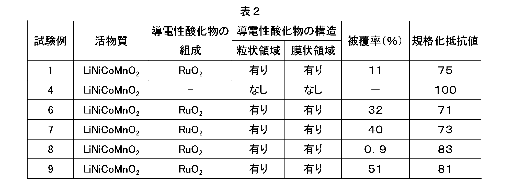
表2に示すように、試験例1、6~9では規格化抵抗値の低下が確認され、これらの中でも試験例1、4、7は規格化抵抗値がより大幅に低下していた。このことから、導電性酸化物からなる粒状領域と膜状領域の両方を正極活物質の表面に付着させる場合には、導電性酸化物の被覆率を0.9%~51%にすることが好ましく、11%~40%にすることがより好ましいことが確認された。
3.試験C
次に、導電性酸化物からなる粒状領域と膜状領域の両方を正極活物質の表面に付着させた正極合材において、導電性酸化物の粒状領域の平均粒子径と、膜状領域の膜厚が電池性能に与える影響を調べるために試験Cを行った。
試験Cにおいては、以下の表3に示すように、粒状領域の平均粒子径と膜状領域の膜厚を異ならせたことを除いて試験Bの試験例6と同じ条件で構築したリチウムイオン二次電池(試験例10~16)に対して規格化抵抗値の測定を行った。
次に、導電性酸化物からなる粒状領域と膜状領域の両方を正極活物質の表面に付着させた正極合材において、導電性酸化物の粒状領域の平均粒子径と、膜状領域の膜厚が電池性能に与える影響を調べるために試験Cを行った。
試験Cにおいては、以下の表3に示すように、粒状領域の平均粒子径と膜状領域の膜厚を異ならせたことを除いて試験Bの試験例6と同じ条件で構築したリチウムイオン二次電池(試験例10~16)に対して規格化抵抗値の測定を行った。
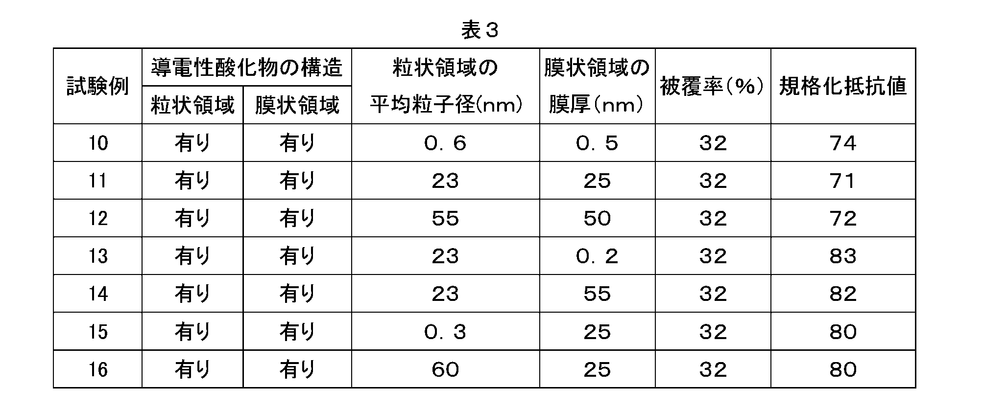
表3に示すように、試験例10~16の何れにおいても、規格化抵抗値の低下が確認されたが、試験例10~12でより大幅な規格化抵抗値の低下が確認された。このことから、粒状領域の平均粒子径を0.6nm~55nmの範囲内にし、かつ、膜状領域の膜厚を0.5nm~50nmの範囲内にすることによって、より高い電池性能を有するリチウムイオン二次電池を構築できることが確認できた。
以上、本発明を詳細に説明したが、上記した実施形態は例示にすぎず、ここで開示される発明には上述の具体例を様々に変形、変更したものが含まれる。
そして、ここに開示される技術により提供されるリチウムイオン二次電池は、上記のように優れた電池性能を示すため、例えば、自動車等の車両に搭載されるモーター(電動機)用電源として好適に使用され得る。また、かかるリチウムイオン二次電池は、それらの複数個を直列および/または並列に接続してなる組電池の形態で使用されてもよい。したがって、ここに開示される技術によれば、リチウムイオン二次電池または該電池を複数備えた組電池を電源として備える車両(典型的には自動車、特にハイブリッド自動車、電気自動車、燃料電池自動車のような電動機を備える自動車)が提供され得る。
1 正極活物質
2a 粒状領域
2b 膜状領域
10 正極
12 正極集電体
14 正極合材層
16 正極合材層非形成部
20 負極
22 負極集電体
24 負極合材層
26 負極合材層非形成部
40 セパレータ
50 ケース
52 ケース本体
54 蓋体
70 正極端子
72 負極端子
80 捲回電極体
100 リチウムイオン二次電池
2a 粒状領域
2b 膜状領域
10 正極
12 正極集電体
14 正極合材層
16 正極合材層非形成部
20 負極
22 負極集電体
24 負極合材層
26 負極合材層非形成部
40 セパレータ
50 ケース
52 ケース本体
54 蓋体
70 正極端子
72 負極端子
80 捲回電極体
100 リチウムイオン二次電池
Claims (8)
- リチウムイオン二次電池の正極に用いられる正極合材であって、
少なくともリチウムを含む層状の結晶構造を有するリチウム複合酸化物からなる粒状の正極活物質と、導電性酸化物とを含み、
ここで、前記正極活物質の表面の少なくとも一部に、前記導電性酸化物の一次粒子が集合した粒状領域と、前記導電性酸化物が膜状に成形された膜状領域とが付着しており、
前記粒状領域における前記一次粒子の断面TEM観察に基づいた平均粒子径が0.3nm以上であり、
前記膜状領域の断面TEM観察において、粒子径が0.3nm以上の粒子が認められず、かつ、2nm以上の空隙が認められない、リチウムイオン二次電池用正極合材。 - 前記導電性酸化物は、一般式(1):
MO2 (1)
(ただし、上記した式(1)中のMは、Va族、VIa族、VIIa族、VIII族およびIb族の遷移金属元素から選択される1種または2種以上の元素である)で示される金属酸化物、または、一般式(2):
ABO3 (2)
(ただし、上記した式(2)中のAは、2価の典型元素、ランタノイド元素またはこれらの組み合わせからなる群から選択される1種または2種以上の元素であり、BはIVa族、Va族、VIa族、VIIa族、VIII族およびIb族の遷移金属元素から選択される1種または2種以上の元素である)で示されるペロブスカイト構造を有する金属酸化物である、請求項1に記載のリチウムイオン二次電池用正極合材。 - 前記導電性酸化物が酸化ルテニウムまたはランタンマンガンコバルト複合酸化物である、請求項2に記載のリチウムイオン二次電池用正極合材。
- 前記正極活物質は、一般式(3):
Li1+αNixCoyMnzMβO2-γAγ (3)
(ただし、上記した式(3)中のMは、Zr、Mo、W、Mg、Ca、Na、Fe、Cr、Zn、Si、Sn、Al、およびBからなる群から選択される1種または2種以上の元素であり、式(3)中のAは、F、Cl、Brからなる群から選択される1種または2種以上の元素であり、x、y、z、α、β、γは、それぞれ、0≦α≦0.7、0≦x<0.9、0≦y<0.4、x+y+z≒1、0≦β≦0.1、0≦γ≦0.5である)で示されるリチウム複合酸化物である、請求項1~請求項3のいずれか一項に記載のリチウムイオン二次電池用正極合材。 - 前記正極活物質の表面における前記導電性酸化物の断面TEM観察に基づいた被覆率が11%~40%である、請求項1~請求項4のいずれか一項に記載のリチウムイオン二次電池用正極合材。
- 前記粒状領域の断面TEM観察に基づいた平均粒子径が0.6nm~55nmであり、
前記膜状領域の断面TEM観察に基づいた膜厚が0.5nm~50nmである、請求項1~請求項5のいずれか一項に記載のリチウムイオン二次電池用正極合材。 - 前記粒状領域と前記膜状領域の少なくとも一部が相互に接触している、請求項1~請求項6のいずれか一項に記載のリチウムイオン二次電池用正極合材。
- 正極集電体上に正極合材層が付与されている正極と、負極集電体上に負極合材層が付与されている負極と、非水電解質と、を備えるリチウムイオン二次電池であって、
前記正極合材層に、少なくともリチウムを含む層状の結晶構造を有するリチウム複合酸化物からなる粒状の正極活物質と、導電性酸化物とが含まれており、
ここで、前記正極活物質の表面の少なくとも一部に、前記導電性酸化物の一次粒子が集合した粒状領域と、前記導電性酸化物が膜状に成形された膜状領域とが付着しており、
前記粒状領域における前記一次粒子の断面TEM観察に基づいた平均粒子径が0.3nm以上であり、
前記膜状領域の断面TEM観察において、粒子径が0.3nm以上の粒子が認められず、かつ、2nm以上の空隙が認められない、リチウムイオン二次電池。
Priority Applications (3)
| Application Number | Priority Date | Filing Date | Title |
|---|---|---|---|
| CN201880010585.1A CN110462893B (zh) | 2017-02-09 | 2018-02-08 | 锂离子二次电池用正极合剂及其使用 |
| US16/484,697 US11108042B2 (en) | 2017-02-09 | 2018-02-08 | Positive electrode composite material for lithium ion secondary battery and use thereof |
| EP18751624.0A EP3582305B8 (en) | 2017-02-09 | 2018-02-08 | Positive electrode composite material for lithium ion secondary battery and use thereof |
Applications Claiming Priority (2)
| Application Number | Priority Date | Filing Date | Title |
|---|---|---|---|
| JP2017-022417 | 2017-02-09 | ||
| JP2017022417A JP6654582B2 (ja) | 2017-02-09 | 2017-02-09 | リチウムイオン二次電池用正極合材およびその利用 |
Publications (1)
| Publication Number | Publication Date |
|---|---|
| WO2018147382A1 true WO2018147382A1 (ja) | 2018-08-16 |
Family
ID=63108316
Family Applications (1)
| Application Number | Title | Priority Date | Filing Date |
|---|---|---|---|
| PCT/JP2018/004450 Ceased WO2018147382A1 (ja) | 2017-02-09 | 2018-02-08 | リチウムイオン二次電池用正極合材およびその利用 |
Country Status (5)
| Country | Link |
|---|---|
| US (1) | US11108042B2 (ja) |
| EP (1) | EP3582305B8 (ja) |
| JP (1) | JP6654582B2 (ja) |
| CN (1) | CN110462893B (ja) |
| WO (1) | WO2018147382A1 (ja) |
Families Citing this family (5)
| Publication number | Priority date | Publication date | Assignee | Title |
|---|---|---|---|---|
| US11251430B2 (en) | 2018-03-05 | 2022-02-15 | The Research Foundation For The State University Of New York | ϵ-VOPO4 cathode for lithium ion batteries |
| JP7085135B2 (ja) * | 2018-10-12 | 2022-06-16 | トヨタ自動車株式会社 | 正極活物質および該正極活物質を備える二次電池 |
| KR102935447B1 (ko) * | 2020-02-04 | 2026-03-05 | 삼성전자주식회사 | 양극, 이를 포함하는 리튬-공기 전지 및 이의 제조 방법 |
| CN112420982A (zh) * | 2020-11-02 | 2021-02-26 | 四川大学 | 一种钙钛矿钒酸盐共混活性材料的电极极片 |
| CN119306265B (zh) * | 2024-12-13 | 2025-05-27 | 帕瓦(诸暨)新能源科技有限公司 | 一种钠离子电池正极材料前驱体及其制备方法与应用 |
Citations (9)
| Publication number | Priority date | Publication date | Assignee | Title |
|---|---|---|---|---|
| JP2000235858A (ja) | 1999-02-15 | 2000-08-29 | Toshiba Corp | 非水電解液二次電池 |
| JP2001266879A (ja) | 2000-03-22 | 2001-09-28 | Toshiba Corp | 非水電解液二次電池 |
| JP2009076446A (ja) | 2007-09-19 | 2009-04-09 | Samsung Sdi Co Ltd | カソード及びそれを採用したリチウム電池 |
| JP2014116111A (ja) * | 2012-12-06 | 2014-06-26 | Sony Corp | 正極活物質およびその製造方法、正極、電池、電池パック、電子機器、電動車両、蓄電装置ならびに電力システム |
| JP2014143032A (ja) * | 2013-01-23 | 2014-08-07 | Hitachi Ltd | リチウムイオン二次電池用正極活物質及びリチウムイオン二次電池 |
| JP2015093907A (ja) * | 2013-11-11 | 2015-05-18 | 国立大学法人東北大学 | 炭化水素の製造方法及び分岐炭化水素の水素化用触媒 |
| JP2016041653A (ja) * | 2013-03-04 | 2016-03-31 | 三井金属鉱業株式会社 | リチウム金属複合酸化物粉体 |
| JP2017022417A (ja) | 2016-10-21 | 2017-01-26 | 大日本印刷株式会社 | テンプレートの製造方法 |
| CN106450270A (zh) * | 2015-08-13 | 2017-02-22 | 中国科学院物理研究所 | 锂离子二次电池的正极活性材料及其制备方法和应用 |
Family Cites Families (14)
| Publication number | Priority date | Publication date | Assignee | Title |
|---|---|---|---|---|
| JP4965773B2 (ja) * | 2001-06-28 | 2012-07-04 | Agcセイミケミカル株式会社 | 非水電解液二次電池用電極活物質及び非水電解液二次電池 |
| JP3876989B2 (ja) * | 2002-05-17 | 2007-02-07 | 三菱化学株式会社 | 表面修飾リチウムニッケル複合酸化物の製造方法並びに表面修飾リチウムニッケル複合酸化物を用いた正極活物質、正極材料、及びリチウム二次電池 |
| JP4794866B2 (ja) * | 2004-04-08 | 2011-10-19 | パナソニック株式会社 | 非水電解質二次電池用正極活物質およびその製造方法ならびにそれを用いた非水電解質二次電池 |
| US20100117033A1 (en) * | 2007-03-05 | 2010-05-13 | Yu-Guo Guo | Material, In Particular For Use In Electrochemical Cells Or Supercapacitors And A Method Of Making Such A Material |
| CN101359733A (zh) * | 2007-07-31 | 2009-02-04 | 比亚迪股份有限公司 | 一种包覆锂离子二次电池正极活性物质的方法 |
| US20100151331A1 (en) * | 2008-12-16 | 2010-06-17 | Enerceramic Inc. | Positive active material and rechargeable lithium battery comprising same |
| CN101872859A (zh) * | 2009-04-24 | 2010-10-27 | 北京圣比和科技有限公司 | 水解沉淀-焙烧法包覆钴酸锂复合氧化物及其制造方法 |
| KR101105879B1 (ko) * | 2009-08-28 | 2012-01-16 | 주식회사 코캄 | 리튬 이차전지용 양극 활물질 및 그 제조방법과 이를 포함하는 리튬 이차전지 |
| KR20130050161A (ko) * | 2011-11-07 | 2013-05-15 | 삼성에스디아이 주식회사 | 전극활물질, 그 제조방법 및 이를 채용한 전극 및 리튬전지 |
| JP2014060050A (ja) * | 2012-09-18 | 2014-04-03 | Honda Motor Co Ltd | 非水電解質二次電池用正極活物質 |
| CN103700827B (zh) | 2012-09-27 | 2016-04-27 | 清华大学 | 锂离子电池正极复合材料及锂离子电池 |
| CN104681784B (zh) * | 2015-02-10 | 2018-03-20 | 华中科技大学 | 一种钒酸锂负极材料、负极、电池以及负极材料制备方法 |
| US12027661B2 (en) * | 2015-06-01 | 2024-07-02 | Forge Nano Inc. | Nano-engineered coatings for anode active materials, cathode active materials, and solid-state electrolytes and methods of making batteries containing nano-engineered coatings |
| US12401042B2 (en) * | 2015-06-01 | 2025-08-26 | Forge Nano Inc. | Nano-engineered coatings for anode active materials, cathode active materials, and solid-state electrolytes and methods of making batteries containing nano-engineered coatings |
-
2017
- 2017-02-09 JP JP2017022417A patent/JP6654582B2/ja active Active
-
2018
- 2018-02-08 US US16/484,697 patent/US11108042B2/en active Active
- 2018-02-08 CN CN201880010585.1A patent/CN110462893B/zh active Active
- 2018-02-08 EP EP18751624.0A patent/EP3582305B8/en active Active
- 2018-02-08 WO PCT/JP2018/004450 patent/WO2018147382A1/ja not_active Ceased
Patent Citations (9)
| Publication number | Priority date | Publication date | Assignee | Title |
|---|---|---|---|---|
| JP2000235858A (ja) | 1999-02-15 | 2000-08-29 | Toshiba Corp | 非水電解液二次電池 |
| JP2001266879A (ja) | 2000-03-22 | 2001-09-28 | Toshiba Corp | 非水電解液二次電池 |
| JP2009076446A (ja) | 2007-09-19 | 2009-04-09 | Samsung Sdi Co Ltd | カソード及びそれを採用したリチウム電池 |
| JP2014116111A (ja) * | 2012-12-06 | 2014-06-26 | Sony Corp | 正極活物質およびその製造方法、正極、電池、電池パック、電子機器、電動車両、蓄電装置ならびに電力システム |
| JP2014143032A (ja) * | 2013-01-23 | 2014-08-07 | Hitachi Ltd | リチウムイオン二次電池用正極活物質及びリチウムイオン二次電池 |
| JP2016041653A (ja) * | 2013-03-04 | 2016-03-31 | 三井金属鉱業株式会社 | リチウム金属複合酸化物粉体 |
| JP2015093907A (ja) * | 2013-11-11 | 2015-05-18 | 国立大学法人東北大学 | 炭化水素の製造方法及び分岐炭化水素の水素化用触媒 |
| CN106450270A (zh) * | 2015-08-13 | 2017-02-22 | 中国科学院物理研究所 | 锂离子二次电池的正极活性材料及其制备方法和应用 |
| JP2017022417A (ja) | 2016-10-21 | 2017-01-26 | 大日本印刷株式会社 | テンプレートの製造方法 |
Non-Patent Citations (1)
| Title |
|---|
| See also references of EP3582305A4 |
Also Published As
| Publication number | Publication date |
|---|---|
| US11108042B2 (en) | 2021-08-31 |
| CN110462893A (zh) | 2019-11-15 |
| EP3582305A1 (en) | 2019-12-18 |
| JP2018129229A (ja) | 2018-08-16 |
| EP3582305B8 (en) | 2023-08-09 |
| EP3582305B1 (en) | 2023-07-05 |
| EP3582305A4 (en) | 2020-03-11 |
| US20200058936A1 (en) | 2020-02-20 |
| CN110462893B (zh) | 2022-06-07 |
| JP6654582B2 (ja) | 2020-02-26 |
Similar Documents
| Publication | Publication Date | Title |
|---|---|---|
| CN103988349B (zh) | 非水系电解质二次电池用正极材料及其制造方法、及使用了该正极材料的非水系电解质二次电池 | |
| US11171326B2 (en) | Positive electrode active material for nonaqueous electrolyte secondary battery, method for producing same, and nonaqueous electrolyte secondary battery using said positive electrode active material | |
| US10784507B2 (en) | Positive electrode active material for nonaqueous electrolyte secondary battery, method for producing same, and nonaqueous electrolyte secondary battery using said positive electrode active material | |
| CN114342121A (zh) | 锂离子二次电池用正极活性物质和锂离子二次电池 | |
| CN111758179B (zh) | 正极、电极组及非水电解质电池 | |
| JP6825978B2 (ja) | リチウムイオン二次電池用正極およびその製造方法 | |
| JP6284040B2 (ja) | リチウム二次電池用正極材料及びその製造方法 | |
| US11967713B2 (en) | Positive electrode active material for non-aqueous electrolyte secondary battery comprising tungsten coating film, and non-aqueous electrolyte secondary battery | |
| CN110462893B (zh) | 锂离子二次电池用正极合剂及其使用 | |
| JP6998107B2 (ja) | 非水系電解質二次電池用正極材料、正極合材、およびそれぞれを用いた非水系電解質二次電池 | |
| JP2010282873A (ja) | リチウム二次電池およびその製造方法 | |
| CN108807865B (zh) | 正极活性物质及其制造方法和锂离子二次电池 | |
| WO2011108119A1 (ja) | リチウム二次電池および該電池に用いられるセパレータ | |
| JP6848199B2 (ja) | 非水系電解質二次電池用正極材料、該正極材料を用いた非水系電解質二次電池、および非水系電解質二次電池用正極材料の製造方法。 | |
| CN112054163B (zh) | 二次电池的正极和使用该正极的二次电池 | |
| JP6354995B2 (ja) | 非水電解質二次電池用正極材料及びその製造方法 | |
| JP2007080583A (ja) | 二次電池用電極と二次電池 | |
| JP6819860B2 (ja) | 非水系電解質二次電池用正極材料、該正極材料を用いた非水系電解質二次電池、および非水系電解質二次電池用正極材料の製造方法。 | |
| JP2020149901A (ja) | リチウムイオン二次電池用正極材料の製造方法、リチウムイオン二次電池用正極材料、リチウムイオン二次電池用正極合材の製造方法、およびリチウムイオン二次電池 | |
| CN116130596A (zh) | 正极和锂离子电池 | |
| CN115461892A (zh) | 非水电解质二次电池用正极活性物质、及非水电解质二次电池 | |
| JP6819861B2 (ja) | 非水系電解質二次電池用正極材料、該正極材料を用いた非水系電解質二次電池、および非水系電解質二次電池用正極材料の製造方法。 | |
| JP2016072031A (ja) | 蓄電素子用正極とそれを用いた蓄電素子及び蓄電装置 | |
| JP2021018898A (ja) | 非水電解質二次電池 | |
| JPWO2014195995A1 (ja) | リチウムイオン二次電池 |
Legal Events
| Date | Code | Title | Description |
|---|---|---|---|
| 121 | Ep: the epo has been informed by wipo that ep was designated in this application |
Ref document number: 18751624 Country of ref document: EP Kind code of ref document: A1 |
|
| NENP | Non-entry into the national phase |
Ref country code: DE |
|
| ENP | Entry into the national phase |
Ref document number: 2018751624 Country of ref document: EP Effective date: 20190909 |