WO2018150984A1 - Ni基溶射合金粉末及び合金皮膜製造方法 - Google Patents
Ni基溶射合金粉末及び合金皮膜製造方法 Download PDFInfo
- Publication number
- WO2018150984A1 WO2018150984A1 PCT/JP2018/004293 JP2018004293W WO2018150984A1 WO 2018150984 A1 WO2018150984 A1 WO 2018150984A1 JP 2018004293 W JP2018004293 W JP 2018004293W WO 2018150984 A1 WO2018150984 A1 WO 2018150984A1
- Authority
- WO
- WIPO (PCT)
- Prior art keywords
- corrosion
- less
- alloy
- alloy powder
- test
- Prior art date
- Legal status (The legal status is an assumption and is not a legal conclusion. Google has not performed a legal analysis and makes no representation as to the accuracy of the status listed.)
- Ceased
Links
Images




Classifications
-
- C—CHEMISTRY; METALLURGY
- C23—COATING METALLIC MATERIAL; COATING MATERIAL WITH METALLIC MATERIAL; CHEMICAL SURFACE TREATMENT; DIFFUSION TREATMENT OF METALLIC MATERIAL; COATING BY VACUUM EVAPORATION, BY SPUTTERING, BY ION IMPLANTATION OR BY CHEMICAL VAPOUR DEPOSITION, IN GENERAL; INHIBITING CORROSION OF METALLIC MATERIAL OR INCRUSTATION IN GENERAL
- C23C—COATING METALLIC MATERIAL; COATING MATERIAL WITH METALLIC MATERIAL; SURFACE TREATMENT OF METALLIC MATERIAL BY DIFFUSION INTO THE SURFACE, BY CHEMICAL CONVERSION OR SUBSTITUTION; COATING BY VACUUM EVAPORATION, BY SPUTTERING, BY ION IMPLANTATION OR BY CHEMICAL VAPOUR DEPOSITION, IN GENERAL
- C23C4/00—Coating by spraying the coating material in the molten state, e.g. by flame, plasma or electric discharge
- C23C4/04—Coating by spraying the coating material in the molten state, e.g. by flame, plasma or electric discharge characterised by the coating material
- C23C4/06—Metallic material
- C23C4/08—Metallic material containing only metal elements
-
- C—CHEMISTRY; METALLURGY
- C22—METALLURGY; FERROUS OR NON-FERROUS ALLOYS; TREATMENT OF ALLOYS OR NON-FERROUS METALS
- C22C—ALLOYS
- C22C19/00—Alloys based on nickel or cobalt
- C22C19/03—Alloys based on nickel or cobalt based on nickel
- C22C19/05—Alloys based on nickel or cobalt based on nickel with chromium
-
- C—CHEMISTRY; METALLURGY
- C22—METALLURGY; FERROUS OR NON-FERROUS ALLOYS; TREATMENT OF ALLOYS OR NON-FERROUS METALS
- C22C—ALLOYS
- C22C19/00—Alloys based on nickel or cobalt
- C22C19/03—Alloys based on nickel or cobalt based on nickel
- C22C19/05—Alloys based on nickel or cobalt based on nickel with chromium
- C22C19/051—Alloys based on nickel or cobalt based on nickel with chromium and Mo or W
- C22C19/055—Alloys based on nickel or cobalt based on nickel with chromium and Mo or W with the maximum Cr content being at least 20% but less than 30%
-
- C—CHEMISTRY; METALLURGY
- C22—METALLURGY; FERROUS OR NON-FERROUS ALLOYS; TREATMENT OF ALLOYS OR NON-FERROUS METALS
- C22C—ALLOYS
- C22C19/00—Alloys based on nickel or cobalt
- C22C19/03—Alloys based on nickel or cobalt based on nickel
- C22C19/05—Alloys based on nickel or cobalt based on nickel with chromium
- C22C19/051—Alloys based on nickel or cobalt based on nickel with chromium and Mo or W
- C22C19/056—Alloys based on nickel or cobalt based on nickel with chromium and Mo or W with the maximum Cr content being at least 10% but less than 20%
-
- C—CHEMISTRY; METALLURGY
- C23—COATING METALLIC MATERIAL; COATING MATERIAL WITH METALLIC MATERIAL; CHEMICAL SURFACE TREATMENT; DIFFUSION TREATMENT OF METALLIC MATERIAL; COATING BY VACUUM EVAPORATION, BY SPUTTERING, BY ION IMPLANTATION OR BY CHEMICAL VAPOUR DEPOSITION, IN GENERAL; INHIBITING CORROSION OF METALLIC MATERIAL OR INCRUSTATION IN GENERAL
- C23C—COATING METALLIC MATERIAL; COATING MATERIAL WITH METALLIC MATERIAL; SURFACE TREATMENT OF METALLIC MATERIAL BY DIFFUSION INTO THE SURFACE, BY CHEMICAL CONVERSION OR SUBSTITUTION; COATING BY VACUUM EVAPORATION, BY SPUTTERING, BY ION IMPLANTATION OR BY CHEMICAL VAPOUR DEPOSITION, IN GENERAL
- C23C4/00—Coating by spraying the coating material in the molten state, e.g. by flame, plasma or electric discharge
- C23C4/04—Coating by spraying the coating material in the molten state, e.g. by flame, plasma or electric discharge characterised by the coating material
- C23C4/06—Metallic material
-
- C—CHEMISTRY; METALLURGY
- C23—COATING METALLIC MATERIAL; COATING MATERIAL WITH METALLIC MATERIAL; CHEMICAL SURFACE TREATMENT; DIFFUSION TREATMENT OF METALLIC MATERIAL; COATING BY VACUUM EVAPORATION, BY SPUTTERING, BY ION IMPLANTATION OR BY CHEMICAL VAPOUR DEPOSITION, IN GENERAL; INHIBITING CORROSION OF METALLIC MATERIAL OR INCRUSTATION IN GENERAL
- C23C—COATING METALLIC MATERIAL; COATING MATERIAL WITH METALLIC MATERIAL; SURFACE TREATMENT OF METALLIC MATERIAL BY DIFFUSION INTO THE SURFACE, BY CHEMICAL CONVERSION OR SUBSTITUTION; COATING BY VACUUM EVAPORATION, BY SPUTTERING, BY ION IMPLANTATION OR BY CHEMICAL VAPOUR DEPOSITION, IN GENERAL
- C23C4/00—Coating by spraying the coating material in the molten state, e.g. by flame, plasma or electric discharge
- C23C4/04—Coating by spraying the coating material in the molten state, e.g. by flame, plasma or electric discharge characterised by the coating material
- C23C4/06—Metallic material
- C23C4/067—Metallic material containing free particles of non-metal elements, e.g. carbon, silicon, boron, phosphorus or arsenic
-
- C—CHEMISTRY; METALLURGY
- C23—COATING METALLIC MATERIAL; COATING MATERIAL WITH METALLIC MATERIAL; CHEMICAL SURFACE TREATMENT; DIFFUSION TREATMENT OF METALLIC MATERIAL; COATING BY VACUUM EVAPORATION, BY SPUTTERING, BY ION IMPLANTATION OR BY CHEMICAL VAPOUR DEPOSITION, IN GENERAL; INHIBITING CORROSION OF METALLIC MATERIAL OR INCRUSTATION IN GENERAL
- C23C—COATING METALLIC MATERIAL; COATING MATERIAL WITH METALLIC MATERIAL; SURFACE TREATMENT OF METALLIC MATERIAL BY DIFFUSION INTO THE SURFACE, BY CHEMICAL CONVERSION OR SUBSTITUTION; COATING BY VACUUM EVAPORATION, BY SPUTTERING, BY ION IMPLANTATION OR BY CHEMICAL VAPOUR DEPOSITION, IN GENERAL
- C23C4/00—Coating by spraying the coating material in the molten state, e.g. by flame, plasma or electric discharge
- C23C4/18—After-treatment
-
- B—PERFORMING OPERATIONS; TRANSPORTING
- B22—CASTING; POWDER METALLURGY
- B22F—WORKING METALLIC POWDER; MANUFACTURE OF ARTICLES FROM METALLIC POWDER; MAKING METALLIC POWDER; APPARATUS OR DEVICES SPECIALLY ADAPTED FOR METALLIC POWDER
- B22F7/00—Manufacture of composite layers, workpieces, or articles, comprising metallic powder, by sintering the powder, with or without compacting wherein at least one part is obtained by sintering or compression
- B22F7/02—Manufacture of composite layers, workpieces, or articles, comprising metallic powder, by sintering the powder, with or without compacting wherein at least one part is obtained by sintering or compression of composite layers
- B22F7/04—Manufacture of composite layers, workpieces, or articles, comprising metallic powder, by sintering the powder, with or without compacting wherein at least one part is obtained by sintering or compression of composite layers with one or more layers not made from powder, e.g. made from solid metal
Definitions
- the present invention relates to a Ni-based sprayed alloy powder and a method for producing an alloy coating, and in particular, a Ni-based sprayed alloy powder capable of forming an alloy coating having excellent environmental resistance in a high temperature environment where corrosion and corrosive wear are a problem.
- the present invention relates to an alloy film manufacturing method.
- HVOF spraying High Velocity Oxygen Fuel
- plasma spraying can reduce the porosity as compared with plasma spraying.
- the pores cannot be completely eliminated, and they are only physically bonded to the substrate. Therefore, by remelting the coating after thermal spraying, a metallurgical reaction layer can be formed with the base material, and pores in the thermal spray coating can be eliminated.
- self-fluxing alloy spraying imparts excellent corrosion resistance because pores in the film are reduced by remelting treatment and invasion of corrosive substances can be suppressed.
- the composition of the self-fluxing alloy powder that can be used for self-fluxing alloy spraying is limited.
- the self-fluxing alloy is required to have a melting point of 1,000 ° C. or less and a wide temperature range between the liquidus and solidus. If the melting point is too high, not only is melting difficult, but there is a concern that the base material may be affected by increasing the temperature to the melting temperature. On the other hand, if the temperature range is narrow, it becomes difficult to control the temperature during the remelting process, and it becomes difficult to form a high-quality film.
- SFNi4 (214A, NiCrCuMoBSi 69, 15, 3A) defined in JIS H8303: 2010.
- SFNi4 is Cr: 12 wt% or more and 17 wt% or less, Mo: 4 wt% or less, Si: 3.5 wt% or more and 5.0 wt% or less, Fe: 5 wt% or less, C: 0.4 wt% or more and 0.9 wt% or less, B : 2.5 wt% or more and 4.0 wt% or less, Co: 1 wt% or less, Cu: 4 wt% or less, the balance is Ni-Cr alloy made of Ni, and has corrosion resistance in a wide range of environments and 50-60 in HRC Therefore, it is an alloy having excellent corrosion resistance and wear resistance. Since SFNi4 is excellent in workability (remelting treatment), it is used in a wide range of fields. For specific applications, an alloy or the like improved from SFNi4 has been proposed
- Ni-based self-fluxing alloy powder that suppresses hot-water flow during remelting treatment, and a part having excellent corrosion resistance and / or wear resistance having a coating film formed by spraying this Ni-based self-fluxing alloy powder. It has been proposed (Patent Document 1).
- Ni-based self-fluxing alloy powder for thermal spraying 5 wt% to 4.5 wt%, B: 1.5 wt% to 4.0 wt%, the balance being Ni and inevitable impurities (Patent Document 3). It is disclosed that this Ni-based self-fluxing alloy powder for thermal spraying is produced by an atomizing method, and chromium carbide having a particle size of 5 ⁇ m or less is uniformly precipitated inside the particles, thereby improving the high temperature erosion property.
- a conventional Ni-based self-fluxing alloy has sufficient environmental resistance against corrosion wear (erosion / corrosion) in which corrosion and wear occur simultaneously.
- An object of the present invention is to provide a Ni-based sprayed alloy powder and an alloy film manufacturing method having excellent corrosion resistance and corrosion wear resistance even in an environment where corrosion or corrosion and wear act simultaneously.
- Embodiments of the present invention are as follows. [1] Cr: 15 wt% or more and 25 wt% or less, Mo: 0 wt% or more and 5 wt% or less, Si: 0.5 wt% or more and less than 2 wt%, Fe: 5 wt% or less, C: 0.3 wt% or more and 0.7 wt% or less And B: Ni-based thermal spray alloy powder characterized by containing 4 wt% or more and 7 wt% or less, the balance being Ni and inevitable impurities.
- Ni-based sprayed alloy powder as described in 1. [3] Mo: 0 wt% or more and 1 wt% or less, Ni-based thermal spray alloy powder according to [1], [4] Mo: 1 wt% or more and 5 wt% or less, Ni-based thermal spray alloy powder according to [1] [5] Remelting the alloy film formed by spraying the Ni-based sprayed alloy powder according to any one of [1] to [4] on the substrate to reduce the porosity in the alloy film; An alloy film manufacturing method characterized by improving adhesion between an alloy film and a substrate. [6] The alloy film manufacturing method according to [5], wherein the remelting is performed by high frequency induction heating.
- Ni-based thermal spray alloy powder of the present invention significantly impairs the heat transfer efficiency of a heat exchanger like a protector even in severe corrosive environments and corrosive wear environments involving chlorides, such as waste, biomass incinerators and boilers. Without this, it is possible to form an alloy film that can extend the life of heat transfer tubes and the like. As a result, it is possible to provide an incinerator or boiler that does not reduce the heat exchange efficiency of the heat transfer tubes and has an increased apparatus operating rate by extending the life of the members.
- the Ni-based thermal spray alloy powder of the present invention has Cr: 15 wt% or more and 25 wt% or less, Mo: 0 wt% or more and 5 wt% or less, Si: 0.5 wt% or more and less than 2.0 wt%, Fe: 5 wt% or less, C: 0 .3 wt% or more and 0.7 wt% or less, and B: 4 wt% or more and 7 wt% or less, and the balance is Ni and inevitable impurities.
- the Si and B contents preferably satisfy ⁇ 0.25B (wt%) + 1.75 ⁇ Si (wt%) ⁇ ⁇ 0.25 B (wt%) + 2.75.
- the composition of the Ni-based sprayed alloy powder of the present invention will be described for each element.
- the Ni-based sprayed alloy powder of the present invention contains Cr: 15 wt% or more and 25 wt% or less, preferably 18 wt% or more and 22 wt% or less.
- Cr is an indispensable element for maintaining corrosion resistance at high temperatures, and if it is less than 15 wt%, sufficient corrosion resistance cannot be exhibited.
- the content is increased, the corrosion resistance is improved, but if it exceeds 25 wt%, the corrosion wear resistance is lowered and the melting point of the alloy is increased, so that the remelting process becomes difficult.
- the Ni-based sprayed alloy powder of the present invention contains Mo: 0 wt% or more and 5 wt% or less.
- Alloy 625 containing 9 wt% Mo is known to exhibit excellent corrosion resistance.
- the corrosion resistance of the Ni-based alloy of the present invention decreases when Mo is added up to 7 wt%.
- the corrosion wear resistance when the content was reduced, the thinning amount was suppressed to a small extent.
- 0 wt% or more and 1 wt% or less with a reduced Mo content is preferable, and when emphasizing corrosion resistance, it is preferably 1 wt% or more and 5 wt% or less.
- the Ni-based sprayed alloy powder of the present invention contains C: 0.3 wt% or more and 0.7 wt% or less.
- C is generally used to form hard Cr carbide and improve the hardness of the sprayed coating.
- Precipitated phases centering on carbides protrude and contribute to the improvement of corrosion wear resistance by mitigating wear received by the Ni base material. If it is less than 0.3 wt%, the carbide phase is insufficient, but if it exceeds 0.7 wt%, Cr in the base material is consumed as carbide and the corrosion resistance is lowered.
- the Ni-based thermal spray alloy powder of the present invention contains Fe: 5 wt% or less.
- Fe dissolves in the Ni base material and improves the strength of the Ni base material.
- Fe is inferior in corrosion resistance at high temperatures compared to Ni, and in particular inferior in chlorinated corrosion resistance, so excessive addition leads to a decrease in corrosion resistance. Addition of 5 wt% or less does not adversely affect corrosion resistance and corrosion wear resistance.
- the Ni-based sprayed alloy powder of the present invention contains B: 4 wt% or more and 7 wt% or less, preferably 5 wt% or more and 6 wt% or less.
- B is an element indispensable for workability (remeltability) and contributes to the hardening of the Ni base material by forming a boride in the alloy.
- Precipitation phase inferior in corrosion resistance is preferentially corroded and corrosion products grow and protrude, resulting in preferential collision with the fluid medium, and as a result, the wear conditions experienced by the Ni base material are alleviated and the amount of thinning is suppressed. It is thought that.
- a corrosive wear test described later it was found that the corrosion resistance is significantly lowered when the B content exceeds 7 wt%.
- the Ni-based sprayed alloy powder of the present invention contains Si: 0.5 wt% or more and less than 2.0 wt%, preferably Si: 0.5 wt% or more and less than 1.5 wt%. It is known that Si is easily bonded to oxygen to form SiO 2 and consumes oxygen in the environment, thereby contributing to improvement of corrosion resistance. As a result of a corrosion test and a corrosion wear resistance test described later, it was found that increasing the Si addition amount improved the corrosion resistance, but increased the thickness reduction and reduced the wear resistance. Moreover, when content of Si was less than 0.5 wt%, it turned out that it is inferior to workability
- the Ni-based thermal sprayed alloy powder of the present invention has a Si and B content of ⁇ 0.25B (wt%) + 1.75 ⁇ Si (wt%) ⁇ ⁇ 0.25 B (wt%) + 2 .75 is satisfied.
- Si is an indispensable element for the workability of the self-fluxing alloy film in order to impart oxidation resistance and self-fluxing.
- the method for producing an alloy film of the present invention comprises remelting an alloy film formed by spraying the Ni-based sprayed alloy powder on a base material, reducing the porosity in the alloy film, and allowing the alloy film to adhere to the base material. It is characterized by improving the performance.
- the remelting is preferably performed by high frequency induction heating.
- the remelting treatment in the method for producing an alloy film of the present invention is preferably performed from the substrate side, not from the film surface side.
- impurities such as oxides entrained during thermal spraying may remain inside the thermal spray coating.
- the impurities float on the surface side and can be removed from the inside of the coating, so that a high-quality thermal spray coating can be formed.
- high frequency induction heating can be preferably used.
- the substrate for spraying the Ni-based sprayed alloy powder of the present invention is not particularly limited, and can be applied to a substrate such as a metal that requires a normal sprayed coating.
- a substrate such as a metal that requires a normal sprayed coating.
- excellent corrosion wear resistance can be imparted.
- FIG. 1 schematically illustrates the configuration of a small fluidized bed test apparatus used in this example.
- the fluidized bed test apparatus 1 includes a container 2 for forming a fluidized bed 4 using a fluidized medium, and an electric furnace 3 provided on the outer periphery of the container 2.
- a glass filter 5 that holds a fluid medium and supplies fluidized air is provided at the bottom of the container 2.
- a test piece holder (water-cooled copper block) 7 for holding the test piece S is provided inside or above the fluidized bed 4 in the test section 6 at the top of the container 2.
- a cooling water conduit 8 for supplying cooling water is connected to the specimen holder 7.
- the test piece S is attached to the test piece holder 7 of the fluidized bed test apparatus 1, the atmospheric gas and the fluid medium in the container 2 are kept at 700 ° C. by external heating by the electric furnace 3, and indirectly by the cooling water supplied to the test piece holder 7.
- the surface of the test piece S was cooled to 350 ° C., a temperature gradient was given to the atmosphere and the test piece, and the actual heat transfer tube environment was reproduced.
- the corrosive environment was reproduced by changing the flow conditions of the fluidized bed 4 by the air supplied from the lower part of the fluidized bed 4 and further mixing the chloride in the fluidized medium.
- the wear resistance generally matches the material hardness
- any material that is hard and excellent in corrosion resistance may be used.
- material characteristics different from hardness (wear resistance) and corrosion resistance are required.
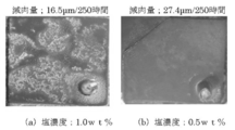
- FIG. 3 shows the state of the surface of the Ni-based self-fluxing alloy after the corrosion wear test. It is the result of having performed the salt thrown in into a fluid medium on two conditions (a) 1.0 wt% and (b) 0.5 wt%. Silica sand having an average particle size of 0.45 mm was used as the fluid medium, and 25 wt% NaCl-25 wt% KCl-50 wt% CaCl 2 mixed salt was used as the salt. An air supply amount for forming the fluidized bed was 20 L / min, and an air amount corresponding to a 2 Umf ratio was allowed to flow. The more salt input, the more severe the corrosive environment.
- the corrosion wear test conditions were the same as those in Test 2 except that the air amount was 25 L / min (2.5 Umf ratio) and the salt concentration was 0.5 wt%.
- the amount of corrosion wear thickness reduction
- the thickness of the test piece before and after the test was measured using a laser thickness meter, and the difference between the thickness of the test piece before the test and the thickness of the test piece after the test was determined.
- the corrosion test evaluation was also performed.
- the test piece was exposed to the upper part of the crucible where the NaCl-KCl-CaCl 2 mixed salt was set, and the corrosion behavior under chloride vapor was investigated.
- a corrosion test was conducted at 530 ° C., which is equal to or higher than the melting point of the mixed salt, for 400 hours, and the weight loss was measured. The amount of corrosion was calculated per 1 cm 2 of the alloy surface area.
- FIG. 4A shows the cross section of the alloy before the test (15.0 kV, 200 times)
- FIG. 4B shows the surface of the test piece after the test (15.0 kV, 200 times)
- FIG. 4C shows the plating for surface protection.
- a large number of precipitated phases are observed in the alloy structure (A) before the test. From the surface (B) and cross section (C) after the test, it can be confirmed that the corrosion product has grown in the portion of the precipitated phase existing on the surface.
- Ni-based sprayed alloy powders with varying amounts of B and Si were prepared, and an alloy coating was formed by flame spraying on the surface of a carbon steel tube for boiler / heat exchanger (STB410) having an outer diameter of 48.6 mm and a wall thickness of 5 mm.
- STB410 boiler / heat exchanger
- the alloy film was remelted by high frequency induction heating from the substrate side.
- the treatment temperature was changed, and the temperature at which the film began to melt and the temperature at which the film became liquid phase and drooped without maintaining the shape were visually confirmed.
- the film starts to melt it can be visually confirmed that the surface is wet and smooth, and this is the lower limit of the construction temperature range.
- the film will drip without maintaining its shape, which is the upper limit of the construction temperature range.
- the construction temperature range is narrow, if the shape of the object to be treated is not a simple shape such as a steel pipe, the construction temperature range is 50 ° C or more because the treatment unevenness due to the uneven heating occurs and the construction becomes impossible.
- this is a criterion for determining whether or not construction is possible.
- a Si amount of at least 0.5% is necessary. Even more preferably, the relationship between Si and B satisfies ⁇ 0.25B + 1.75 ⁇ Si ⁇ ⁇ 0.25B + 2.75.
- FIG. 6 shows the Ni-based thermal spray alloy of the present invention (No. 16 in Table 2) and an alloy in which Si and B are out of the scope of the present invention (comparative alloy; Si of No. 16 is 4 wt% and B is 0 wt%).
- the result of differential thermal analysis (changed) was raised to 1500 ° C. at 20 ° C./min and cooled at 20 ° C./min. It can be seen from the Ni-based sprayed alloy of the present invention (FIG. 6A) that a large endothermic peak exists at 977 ° C. from the DTA curve at the time of temperature rise and melting starts.
- the Ni-based sprayed alloy of the present invention has a melting start temperature of 1,000 ° C. or less and a temperature range between a liquidus and a solidus of 100 ° C. or more (165 ° C.).
- the comparative alloy FIG. 6B
- an endothermic peak at 1321 ° C. and an exothermic peak at 1331 ° C. are observed in the DTA curve at the time of temperature rise, and the melting start temperature greatly exceeds 1000 ° C. It can be seen that the temperature range between the phase line and the solid phase line is also as small as 10 ° C.
- Each of Examples 1 to 4 is excellent in corrosion wear resistance, and the corrosion resistance is equal to or higher than that of the reference example (conventional product).
- the corrosion wear resistance is equivalent to that of Examples 1 to 4, but the corrosion amount is twice as large and the corrosion resistance is poor.
- Comparative Example 2 with a high Cr content and Comparative Example 3 with a high Si content have a large amount of corrosion wear and are inferior in corrosion wear resistance.
- a Ni-based sprayed alloy powder and a method for producing an alloy film that have corrosion resistance comparable to or higher than that of conventional products and that have excellent corrosion wear resistance.
- the life of the apparatus can be extended by applying a thermal spray coating on a heat transfer tube or the like.
- Fluidized bed test apparatus 2 Container 3: Electric furnace 4: Fluidized bed 5: Glass filter 6: Test unit 7: Test piece holder 8: Cooling water conduit S: Test piece
Landscapes
- Chemical & Material Sciences (AREA)
- Engineering & Computer Science (AREA)
- Materials Engineering (AREA)
- Mechanical Engineering (AREA)
- Metallurgy (AREA)
- Organic Chemistry (AREA)
- Physics & Mathematics (AREA)
- Plasma & Fusion (AREA)
- Chemical Kinetics & Catalysis (AREA)
- Coating By Spraying Or Casting (AREA)
- Powder Metallurgy (AREA)
Abstract
腐食もしくは腐食と摩耗が同時に作用する環境下においても優れた耐食性及び耐腐食摩耗性を有するNi基溶射合金粉末及び合金皮膜製造方法を提供する。 Cr:15wt%以上25wt%以下、Mo:0wt%以上5wt%以下、Si:0.5wt%以上2wt%未満、Fe:5wt%以下、C:0.3wt%以上0.7wt%以下、及びB:4wt%以上7wt%以下を含み、残部はNi及び不可避的不純物であることを特徴とするNi基溶射合金粉末。
Description
本発明は、Ni基溶射合金粉末及び合金皮膜製造方法に関し、特に腐食ならびに腐食摩耗が問題となる高温環境下で、耐環境性に優れた合金皮膜を形成することができるNi基溶射合金粉末及び合金皮膜製造方法に関する。
廃棄物やバイオマスなどの焼却炉内には、燃料中に含まれる塩素により厳しい高温腐食環境が形成される。特に、雰囲気温度よりも低温の熱交換器の表面には、雰囲気中に含まれていた塩化物が濃縮されて堆積するため、激しい腐食が生じる。さらに流動床式ボイラーの場合、腐食に加え、流動媒体による摩耗が作用することにより激しい減肉が生じる場合がある。これらへの減肉対策として、プロテクターの装着が行われている。プロテクターの装着は有効であるが、熱交換器においては伝熱効率の低下を招く。そのため、減肉対策として、溶射などの表面処理が用いられることが多々ある。
溶射皮膜の一般的な課題として、皮膜中の気孔および基材との密着力が挙げられる。溶射時の粒子速度を高速化したHVOF溶射(High Velocity Oxygen Fuel)などは、プラズマ溶射に比べ気孔率を低減させることが可能である。しかし完全に気孔を無くすことはできず、また基材とも物理的に接合しているのみである。そこで、溶射後に皮膜を再溶融することにより、基材と冶金学的な反応層を形成させ、かつ溶射皮膜中の気孔を無くすことができ、溶射皮膜の特性を格段に向上させる自溶合金溶射法が用いられている。自溶合金溶射は、再溶融処理により皮膜中の気孔が減少し、腐食性物質の侵入が抑制できるため、優れた耐食性を付与することが知られている。しかし、自溶合金溶射に用いることができる自溶合金粉末の組成は限定されている。自溶合金には、1,000℃以下に融点を有し、液相線と固相線の温度幅が広いことが求められる。融点が高過ぎると溶融が困難になるのみならず、溶融温度まで温度を上げることにより母材に対する熱影響を及ぼすことが懸念される。一方、温度幅が狭いと、再溶融処理時の温度制御が難しくなり、良質な皮膜が出来難くなる。
自溶合金粉末として最も一般的に用いられるのがJIS H8303:2010に規定されているSFNi4(214A NiCrCuMoBSi 69 15 3 3A)である。SFNi4はCr:12wt%以上17wt%以下、Mo:4wt%以下、Si:3.5wt%以上5.0wt%以下、Fe:5wt%以下、C:0.4wt%以上0.9wt%以下、B:2.5wt%以上4.0wt%以下、Co:1wt%以下、Cu:4wt%以下、残部はNiからなるNi-Cr合金であり、幅広い環境での耐食性を有すると共に、HRCで50~60の高硬度を有するため、耐食性ならびに耐摩耗性に優れる合金である。SFNi4は、施工性(再溶融処理)にも優れるため、幅広い分野で使われている。また、特定の用途に対しては、SFNi4を改良した合金なども提案されている。
例えば、Cr:10wt%~16.5wt%、Mo:4.0wt%以下、Si:3.0wt%~5.0wt%、Fe:15.0wt%以下、C:0.01wt%~0.9wt%、B:2.0wt%~4.0wt%、Cu:3.0wt%以下、O:50ppm~500ppm、残部はNi及び不可避的不純物からなり、Si/B:1.2~1.7を満たす、再溶融処理時の湯流れ性を抑えたNi基自溶性合金粉末、及びこのNi基自溶性合金粉末を溶射法により成膜した皮膜を有する耐食性および/または耐摩耗性に優れた部品が提案されている(特許文献1)。
また、Cr:12wt%~17wt%、Mo:3wt%~8wt%、Si:3.5wt%~5.0wt%、Fe:5.0wt%以下、C:0.4wt%~0.9wt%、B:2.5wt%~4.0wt%、Cu:4.0wt%以下、O:200ppm以下、残部はNi及び不可避的不純物からなり、0ppm≧-20Mo%+100を満たすNi基自溶性合金粉末が提案されている(特許文献2)。
さらに、Cr:30.0wt%~42.0wt%、Mo:0.5wt%~2.0wt%、Si:2.0wt%~4.0wt%、Fe:5.0wt%以下、C:2.5wt%~4.5wt%、B:1.5wt%~4.0wt%、残部はNi及び不可避的不純物である溶射用Ni基自溶合金粉末が提案されている(特許文献3)。この溶射用Ni基自溶合金粉末は、アトマイズ法により作製され、粒子内部に粒径5μm以下のクロムカーバイドが均一に析出しており、高温エロージョン性が向上することが開示されている。
さらに、Cr:12wt%~17wt%、Mo:4wt%以下、Si:3.5wt%~5.0wt%、Fe:5.0wt%以下、C:0.4wt%~0.9wt%、B:2.5wt%~4.5wt%、Cu:4.0wt%以下、残部はNi及び不可避的不純物を含むNi基自溶性合金よりなる保護皮膜が形成されている熱交換用耐食・耐摩耗性伝熱管が提案されている(特許文献4)。
しかし、従来のNi基自溶合金は、腐食と摩耗が同時に生じる腐食摩耗(エロージョン・コロージョン)に対して十分な耐環境性を有しているとは言えない。
本発明は、腐食もしくは腐食と摩耗が同時に作用する環境下においても優れた耐食性及び耐腐食摩耗性を有するNi基溶射合金粉末及び合金皮膜製造方法を提供することを目的とする。
本発明者らは上記課題を解決するべく鋭意研究した結果、Ni基合金中のSiおよびBの含有量を最適化することに着目し、本発明を完成するに至った。
本発明の実施態様は以下のとおりである。
[1]Cr:15wt%以上25wt%以下、Mo:0wt%以上5wt%以下、Si:0.5wt%以上2wt%未満、Fe:5wt%以下、C:0.3wt%以上0.7wt%以下、及びB:4wt%以上7wt%以下を含み、残部はNi及び不可避的不純物であることを特徴とするNi基溶射合金粉末。
[2]Si及びBの含有量は、-0.25B(wt%)+1.75≦Si(wt%)≦-0.25B(wt%)+2.75を満たすことを特徴とする[1]に記載のNi基溶射合金粉末。
[3]Mo:0wt%以上1wt%以下であることを特徴とする[1]に記載のNi基溶射合金粉末。
[4]Mo:1wt%以上5wt%以下であることを特徴とする[1]に記載のNi基溶射合金粉末。
[5]基材に[1]~[4]のいずれか1項に記載のNi基溶射合金粉末を溶射して形成した合金皮膜を再溶融させて、合金皮膜中の気孔率を低減させ、合金皮膜と基材との密着性を向上させることを特徴とする合金皮膜製造方法。
[6]前記再溶融は高周波誘導加熱によりなされることを特徴とする[5]に記載の合金皮膜製造方法。
[1]Cr:15wt%以上25wt%以下、Mo:0wt%以上5wt%以下、Si:0.5wt%以上2wt%未満、Fe:5wt%以下、C:0.3wt%以上0.7wt%以下、及びB:4wt%以上7wt%以下を含み、残部はNi及び不可避的不純物であることを特徴とするNi基溶射合金粉末。
[2]Si及びBの含有量は、-0.25B(wt%)+1.75≦Si(wt%)≦-0.25B(wt%)+2.75を満たすことを特徴とする[1]に記載のNi基溶射合金粉末。
[3]Mo:0wt%以上1wt%以下であることを特徴とする[1]に記載のNi基溶射合金粉末。
[4]Mo:1wt%以上5wt%以下であることを特徴とする[1]に記載のNi基溶射合金粉末。
[5]基材に[1]~[4]のいずれか1項に記載のNi基溶射合金粉末を溶射して形成した合金皮膜を再溶融させて、合金皮膜中の気孔率を低減させ、合金皮膜と基材との密着性を向上させることを特徴とする合金皮膜製造方法。
[6]前記再溶融は高周波誘導加熱によりなされることを特徴とする[5]に記載の合金皮膜製造方法。
本発明のNi基溶射合金粉末は、廃棄物、バイオマス焼却炉やボイラーなど、塩化物が関与する厳しい高温における腐食環境や腐食摩耗環境下でも、プロテクターのように熱交換器の伝熱効率を著しく損なうこと無しに、伝熱管などの延命化を可能にする合金皮膜を形成することができる。その結果、伝熱管の熱交換効率を低下させることなく、かつ部材の延命化による装置稼動率を高めた焼却炉やボイラーを提供することができる。
本発明のNi基溶射合金粉末は、Cr:15wt%以上25wt%以下、Mo:0wt%以上5wt%以下、Si:0.5wt%以上2.0wt%未満、Fe:5wt%以下、C:0.3wt%以上0.7wt%以下、及びB:4wt%以上7wt%以下を含み、残部はNi及び不可避的不純物であることを特徴とする。また、Si及びBの含有量は、-0.25B(wt%)+1.75≦Si(wt%)≦-0.25B(wt%)+2.75を満たすことが好ましい。以下、本発明のNi基溶射合金粉末の組成を元素別に説明する。
[Cr:15wt%以上25wt%以下]
本発明のNi基溶射合金粉末はCr:15wt%以上25wt%以下、好ましくは18wt%以上22wt%以下を含む。Crは高温での耐食性を維持するために不可欠な元素であり、15wt%より少ないと十分な耐食性を発揮することができない。一方、含有量を増やすと耐食性は向上するが、25wt%を越えると耐腐食摩耗性が低下するとともに、合金の融点が上昇するため再溶融処理が難しくなる。
本発明のNi基溶射合金粉末はCr:15wt%以上25wt%以下、好ましくは18wt%以上22wt%以下を含む。Crは高温での耐食性を維持するために不可欠な元素であり、15wt%より少ないと十分な耐食性を発揮することができない。一方、含有量を増やすと耐食性は向上するが、25wt%を越えると耐腐食摩耗性が低下するとともに、合金の融点が上昇するため再溶融処理が難しくなる。
[Mo:0wt%以上5wt%以下]
本発明のNi基溶射合金粉末はMo:0wt%以上5wt%以下を含む。ごみ焼却炉に代表される塩化腐食環境では、Moを9wt%含有するAlloy625が優れた耐食性を発揮することが知られている。しかし、後述する腐食試験を実施した結果、本発明のNi基合金においては、Moを7wt%まで添加すると耐食性が逆に低下することがわかった。一方、耐腐食摩耗性については含有量を減らすと若干ではあるが減肉量が抑えられる結果となった。耐腐食摩耗性を重視する場合はMo含有量を抑えた0wt%以上1wt%以下が好ましく、耐食性を重視する場合は1wt%以上5wt%以下とすることが好ましい。
本発明のNi基溶射合金粉末はMo:0wt%以上5wt%以下を含む。ごみ焼却炉に代表される塩化腐食環境では、Moを9wt%含有するAlloy625が優れた耐食性を発揮することが知られている。しかし、後述する腐食試験を実施した結果、本発明のNi基合金においては、Moを7wt%まで添加すると耐食性が逆に低下することがわかった。一方、耐腐食摩耗性については含有量を減らすと若干ではあるが減肉量が抑えられる結果となった。耐腐食摩耗性を重視する場合はMo含有量を抑えた0wt%以上1wt%以下が好ましく、耐食性を重視する場合は1wt%以上5wt%以下とすることが好ましい。
[C:0.3wt%以上0.7wt%以下]
本発明のNi基溶射合金粉末はC:0.3wt%以上0.7wt%以下を含む。Cは硬いCr炭化物などを形成し、溶射皮膜の硬度を向上させることに用いられることが一般的である。炭化物を中心にした析出相が突出し、Ni母材が受ける摩耗を緩和することにより耐腐食摩耗性の向上に寄与する。0.3wt%未満では炭化物相が不十分であるが、0.7wt%を越えると母材中のCrが炭化物として消費され、耐食性が低下する。
本発明のNi基溶射合金粉末はC:0.3wt%以上0.7wt%以下を含む。Cは硬いCr炭化物などを形成し、溶射皮膜の硬度を向上させることに用いられることが一般的である。炭化物を中心にした析出相が突出し、Ni母材が受ける摩耗を緩和することにより耐腐食摩耗性の向上に寄与する。0.3wt%未満では炭化物相が不十分であるが、0.7wt%を越えると母材中のCrが炭化物として消費され、耐食性が低下する。
[Fe:5wt%以下]
本発明のNi基溶射合金粉末はFe:5wt%以下を含む。FeはNi母材中に固溶し、Ni母材の強度を向上させる。しかし、FeはNiに比べ高温での耐食性に劣り、特に耐塩化腐食性に劣るため、過度の添加は耐食性の低下に繋がる。5wt%以下の添加であれば、耐食性および耐腐食摩耗性に対し悪影響を及ぼさない。
本発明のNi基溶射合金粉末はFe:5wt%以下を含む。FeはNi母材中に固溶し、Ni母材の強度を向上させる。しかし、FeはNiに比べ高温での耐食性に劣り、特に耐塩化腐食性に劣るため、過度の添加は耐食性の低下に繋がる。5wt%以下の添加であれば、耐食性および耐腐食摩耗性に対し悪影響を及ぼさない。
[B:4wt%以上7wt%以下]
本発明のNi基溶射合金粉末はB:4wt%以上7wt%以下、好ましくは5wt%以上6wt%以下を含む。Bは施工性(再溶融性)に不可欠な元素であると共に、合金中で硼化物を形成してNi母材の硬化に寄与する。耐食性に劣る析出相が優先的に腐食されて腐食生成物が成長および突出することにより優先的に流動媒体の衝突を受け、結果としてNi母材が受ける摩耗条件を緩和し、減肉量を抑制すると考えられる。後述する腐食摩耗試験の結果、Bの含有量が7wt%を越えると耐食性が著しく低下することがわかった。
本発明のNi基溶射合金粉末はB:4wt%以上7wt%以下、好ましくは5wt%以上6wt%以下を含む。Bは施工性(再溶融性)に不可欠な元素であると共に、合金中で硼化物を形成してNi母材の硬化に寄与する。耐食性に劣る析出相が優先的に腐食されて腐食生成物が成長および突出することにより優先的に流動媒体の衝突を受け、結果としてNi母材が受ける摩耗条件を緩和し、減肉量を抑制すると考えられる。後述する腐食摩耗試験の結果、Bの含有量が7wt%を越えると耐食性が著しく低下することがわかった。
[Si:0.5wt%以上2.0wt%未満]
本発明のNi基溶射合金粉末はSi:0.5wt%以上2.0wt%未満、好ましくはSi:0.5wt%以上1.5wt%未満を含む。Siは酸素と結合してSiO2を形成しやすく、環境中の酸素を消費するため、耐食性向上に寄与することが知られている。後述する腐食試験及び耐腐食摩耗性試験の結果、Si添加量を増やすと耐食性が向上するが、減肉量が増加し耐摩耗性が低下することがわかった。また、Siの含有量を0.5wt%よりも少なくすると、施工性(再溶融処理)に劣り、十分に再溶融せず、十分に緻密な皮膜を形成できないことがわかった。
本発明のNi基溶射合金粉末はSi:0.5wt%以上2.0wt%未満、好ましくはSi:0.5wt%以上1.5wt%未満を含む。Siは酸素と結合してSiO2を形成しやすく、環境中の酸素を消費するため、耐食性向上に寄与することが知られている。後述する腐食試験及び耐腐食摩耗性試験の結果、Si添加量を増やすと耐食性が向上するが、減肉量が増加し耐摩耗性が低下することがわかった。また、Siの含有量を0.5wt%よりも少なくすると、施工性(再溶融処理)に劣り、十分に再溶融せず、十分に緻密な皮膜を形成できないことがわかった。
[-0.25B(wt%)+1.75≦Si(wt%)≦-0.25B(wt%)+2.75]
本発明のNi基溶射合金粉末は、上記組成に加えて、Si及びBの含有量が-0.25B(wt%)+1.75≦Si(wt%)≦-0.25B(wt%)+2.75を満たす。耐摩耗性を向上させるためには、Siの含有量を少なくすることが好ましいが、Siは耐酸化性や自溶性を付与するために自溶合金皮膜の施工性には不可欠な元素である。後述する腐食試験及び腐食摩耗性試験の結果、Si及びBの含有量が-0.25B(wt%)+1.75≦Si(wt%)≦-0.25B(wt%)+2.75を満たす条件においてSiを減らしてもBを増やすことで再溶融できることがわかった。
本発明のNi基溶射合金粉末は、上記組成に加えて、Si及びBの含有量が-0.25B(wt%)+1.75≦Si(wt%)≦-0.25B(wt%)+2.75を満たす。耐摩耗性を向上させるためには、Siの含有量を少なくすることが好ましいが、Siは耐酸化性や自溶性を付与するために自溶合金皮膜の施工性には不可欠な元素である。後述する腐食試験及び腐食摩耗性試験の結果、Si及びBの含有量が-0.25B(wt%)+1.75≦Si(wt%)≦-0.25B(wt%)+2.75を満たす条件においてSiを減らしてもBを増やすことで再溶融できることがわかった。
次に、本発明の合金皮膜製造方法を説明する。
本発明の合金皮膜製造方法は、上記Ni基溶射合金粉末を基材に溶射して形成した合金皮膜を再溶融させて、合金皮膜中の気孔率を低減させ、合金皮膜と基材との密着性を向上させることを特徴とする。前記再溶融は高周波誘導加熱によりなされることが好ましい。
再溶融処理の方法としては、バーナー加熱や電気炉を使った熱処理などの代表的な手法、及び高周波誘導加熱を制限なく用いることができる。本発明の合金皮膜製造方法における再溶融処理は、皮膜表面側からの加熱ではなく、基材側から加熱することが好ましい。皮膜表面側から加熱すると、溶射時に巻き込まれた酸化物などの不純物が溶射皮膜内部に残存することがある。基材側から加熱すると、不純物が表面側に浮き上がり皮膜内部から除去することができるため、良質な溶射皮膜を形成することが可能になる。基材側から加熱する方法として、高周波誘導加熱を好ましく用いることができる。
本発明のNi基溶射合金粉末を溶射する基材としては特に限定されず、通常の溶射皮膜を必要とする金属などの基材に適用することができる。特に、厳しい腐食摩耗環境下で使用する伝熱管などに適用する場合に優れた耐腐食摩耗性を付与することができる。
図1に、本実施例で用いた小型の流動層試験装置の構成を概略説明する。
流動層試験装置1は、流動媒体による流動層4を形成させる容器2と、容器2の外周に設けられている電気炉3とを具備する。容器2の底部には流動媒体を保持し且つ流動化空気を供給するガラスフィルタ5が設けられている。容器2の上部の試験部6には、流動層4の内部又は上方に試験片Sを保持する試験片ホルダー(水冷銅ブロック)7が設けられている。試験片ホルダー7には冷却水を供給する冷却水導管8が接続されている。
流動層試験装置1の試験片ホルダー7に試験片Sを取り付け、電気炉3による外部加熱により容器2内の雰囲気ガスおよび流動媒体を700℃に保ち、試験片ホルダー7に供給する冷却水により間接冷却することによって試験片Sの表面を350℃に冷却し、雰囲気と試験片に温度勾配を付け、実機の伝熱管環境を再現した。流動層4の下部から供給する空気により流動層4の流動条件を変化させ、さらに流動媒体中に塩化物を混合させて腐食性の環境を再現した。
[試験1]
流動層試験装置1を用いて、腐食環境及び腐食摩耗環境でのNi基合金の減肉特性を調べた。図2は、塩化物存在下で、砂が流動している層内(腐食摩耗環境:erosion-corrosion)と、砂による摩耗の影響がない層の上部(腐食環境:corrosion)の2箇所に試験片Sを設置し、それぞれの減肉量(Metal loss)を調査した結果を示すグラフである。図2から明らかなように、Cr含有量(Cr content in alloys)が多いほど腐食量は減少し耐食性が向上するが、逆に減肉量は増加し耐摩耗性は低下することがわかった。耐摩耗性は材料硬さと概ね一致するため、耐摩耗性と共に耐食性を有するためには、硬くて耐食性に優れる材料であればよい。しかし、図2の結果から、耐腐食摩耗性を有するためには、硬さ(耐摩耗性)や耐食性とは異なる材料特性が求められることが判明した。
流動層試験装置1を用いて、腐食環境及び腐食摩耗環境でのNi基合金の減肉特性を調べた。図2は、塩化物存在下で、砂が流動している層内(腐食摩耗環境:erosion-corrosion)と、砂による摩耗の影響がない層の上部(腐食環境:corrosion)の2箇所に試験片Sを設置し、それぞれの減肉量(Metal loss)を調査した結果を示すグラフである。図2から明らかなように、Cr含有量(Cr content in alloys)が多いほど腐食量は減少し耐食性が向上するが、逆に減肉量は増加し耐摩耗性は低下することがわかった。耐摩耗性は材料硬さと概ね一致するため、耐摩耗性と共に耐食性を有するためには、硬くて耐食性に優れる材料であればよい。しかし、図2の結果から、耐腐食摩耗性を有するためには、硬さ(耐摩耗性)や耐食性とは異なる材料特性が求められることが判明した。
[試験2]
図3に腐食摩耗試験後のNi基自溶合金の表面の状態を示す。流動媒体中に投入する塩を(a)1.0wt%および(b)0.5wt%の2条件で行った結果である。流動媒体としては平均粒径0.45mmの珪砂、塩としては25wt%NaCl-25wt%KCl-50wt%CaCl2混合塩を用いた。流動層を形成するための空気供給量は20L/minとし、2Umf比に相当する空気量を流した。塩の投入量が多いほど腐食環境は厳しくなる。試験後の試験片表面を観察すると、(a)塩濃度1.0wt%の場合は、表面が腐食生成物で覆われていたが、(b)塩濃度0.5wt%の場合は、表面が滑らかで明瞭な腐食生成物は観察されず、金属素地が露出に近い状態であった。両者の250時間後の減肉量を比較すると、(a)塩濃度1.0wt%で16.5μm、(b)塩濃度0.5wt%では27.4μmとなり、腐食条件の穏やかな塩濃度0.5wt%で減肉量が増加していた。腐食環境が厳しいと腐食生成物の成長速度が速く、合金表面が速やかに腐食生成物で覆われて保護皮膜を形成し、その後の腐食並びに摩耗を抑制するのに対し、腐食環境が穏やかであると腐食生成物の成長速度が遅く、生成した腐食生成物が摩耗により損傷を受けるため保護皮膜を形成することができず、速い速度で腐食が進行し続けるためと考えられる。このことからも、耐腐食摩耗性を有するためには、単純な耐食性や耐摩耗性ではなく、腐食並びに摩耗を十分に抑制できる腐食生成物を速やかに形成させることが重要なポイントとなることが確認できた。
図3に腐食摩耗試験後のNi基自溶合金の表面の状態を示す。流動媒体中に投入する塩を(a)1.0wt%および(b)0.5wt%の2条件で行った結果である。流動媒体としては平均粒径0.45mmの珪砂、塩としては25wt%NaCl-25wt%KCl-50wt%CaCl2混合塩を用いた。流動層を形成するための空気供給量は20L/minとし、2Umf比に相当する空気量を流した。塩の投入量が多いほど腐食環境は厳しくなる。試験後の試験片表面を観察すると、(a)塩濃度1.0wt%の場合は、表面が腐食生成物で覆われていたが、(b)塩濃度0.5wt%の場合は、表面が滑らかで明瞭な腐食生成物は観察されず、金属素地が露出に近い状態であった。両者の250時間後の減肉量を比較すると、(a)塩濃度1.0wt%で16.5μm、(b)塩濃度0.5wt%では27.4μmとなり、腐食条件の穏やかな塩濃度0.5wt%で減肉量が増加していた。腐食環境が厳しいと腐食生成物の成長速度が速く、合金表面が速やかに腐食生成物で覆われて保護皮膜を形成し、その後の腐食並びに摩耗を抑制するのに対し、腐食環境が穏やかであると腐食生成物の成長速度が遅く、生成した腐食生成物が摩耗により損傷を受けるため保護皮膜を形成することができず、速い速度で腐食が進行し続けるためと考えられる。このことからも、耐腐食摩耗性を有するためには、単純な耐食性や耐摩耗性ではなく、腐食並びに摩耗を十分に抑制できる腐食生成物を速やかに形成させることが重要なポイントとなることが確認できた。
[試験3]
これらの観点から、表1に示す種々の組成を有するNi-Cr合金における元素の影響を評価した。
これらの観点から、表1に示す種々の組成を有するNi-Cr合金における元素の影響を評価した。
腐食摩耗試験条件は、空気量を25L/min(2.5Umf比)、塩濃度は0.5wt%とした以外は、試験2と同様とした。腐食摩耗量(減肉量)は、レーザー厚み計を用いて試験前後の試験片厚みを測定し、試験前の試験片厚みと試験後の試験片厚みの差を求めた。
実機での使用を考えた場合、摩耗条件が穏やかで腐食が主体となる環境も存在し、耐食性が極端に低下することは望ましくないため、腐食試験評価も併せて実施した。前記NaCl-KCl-CaCl2混合塩をセットしたるつぼの上部に試験片を曝し、塩化物蒸気下での腐食挙動を調査した。混合塩の融点以上の530℃で400時間腐食試験を行い、重量減少量を測定し、合金表面積1cm2当たりに換算して腐食量を求めた。
腐食摩耗試験及び腐食試験の結果を表1にまとめて示す。

[試験4]
施工可能な合金組成範囲を検討し、Siを減らしてもBを増やすことで再溶融できることを見出した。結果を図5に示す。
施工可能な合金組成範囲を検討し、Siを減らしてもBを増やすことで再溶融できることを見出した。結果を図5に示す。
BおよびSi量を変化させたNi基溶射合金粉末を作製し、外径48.6mm、肉厚5mmのボイラ・熱交換器用炭素鋼管(STB410)の表面にフレーム溶射にて合金皮膜を形成した。次に、基材側から高周波誘導加熱して合金皮膜を再溶融させた。その際に、処理温度を変化させて、皮膜が溶け始める温度および皮膜の液相化が進んで形状が保持できずに垂れる温度を目視にて確認した。皮膜が溶け始めると、表面が濡れてきて平滑になることが目視にて確認でき、これが施工温度範囲の下限となる。過加熱になると、皮膜が形状を保持できずに垂れてしまうため、施工温度範囲の上限となる。施工温度範囲が狭いと、被処理物の形状が鋼管などの単純形状でない場合に、加熱むらに起因する処理むらが生じて施工不可となるため、施工温度範囲が50℃以上の範囲であることが、施工可否の判定基準となる。その結果、最低0.5%以上のSi量が必要であることを見出した。さらにより好ましくは、SiとBの関係が、-0.25B+1.75≦Si≦-0.25B+2.75を満たすことである。
[試験5]
図6に、本発明のNi基溶射合金(表2のNo.16)と、SiおよびBが本発明の範囲外の合金(比較合金;No.16のSiを4wt%、Bを0wt%に変更した)の示差熱分析(20℃/minにて1500℃まで昇温し、20℃/minで冷却した)結果を示す。本発明のNi基溶射合金(図6A)より、昇温時のDTA曲線から977℃に大きな吸熱ピークが存在し、溶融が始まることがわかる。そして降温時のDTA曲線から1142℃に大きな発熱ピークが存在し、凝固が始まることがわかる。以上より、本発明のNi基溶射合金は1,000℃以下の溶融開始温度と、100℃以上(165℃)の液相線と固相線の間の温度幅を有しているといえる。一方、比較合金(図6B)においては、昇温時のDTA曲線に1321℃吸熱ピークと降温時のDTA曲線に1331℃の発熱ピークが見られ、溶融開始温度は1000℃を大きく超え、また液相線と固相線の間の温度幅も10℃と小さいことがわかる。
図6に、本発明のNi基溶射合金(表2のNo.16)と、SiおよびBが本発明の範囲外の合金(比較合金;No.16のSiを4wt%、Bを0wt%に変更した)の示差熱分析(20℃/minにて1500℃まで昇温し、20℃/minで冷却した)結果を示す。本発明のNi基溶射合金(図6A)より、昇温時のDTA曲線から977℃に大きな吸熱ピークが存在し、溶融が始まることがわかる。そして降温時のDTA曲線から1142℃に大きな発熱ピークが存在し、凝固が始まることがわかる。以上より、本発明のNi基溶射合金は1,000℃以下の溶融開始温度と、100℃以上(165℃)の液相線と固相線の間の温度幅を有しているといえる。一方、比較合金(図6B)においては、昇温時のDTA曲線に1321℃吸熱ピークと降温時のDTA曲線に1331℃の発熱ピークが見られ、溶融開始温度は1000℃を大きく超え、また液相線と固相線の間の温度幅も10℃と小さいことがわかる。
[試験6]
表2に示す組成のNi基溶射合金粉末を作製し、試験3と同様の腐食摩耗試験及び腐食試験により評価した。
表2に示す組成のNi基溶射合金粉末を作製し、試験3と同様の腐食摩耗試験及び腐食試験により評価した。

以上のとおり、本発明によれば、従来品と同程度以上の耐食性を有し、かつ耐腐食摩耗性に優れたNi基溶射合金粉末および合金皮膜製造方法が提供される。本発明のNi基溶射合金粉末を用いて、バイオマスなど塩素を含む原料を燃料とする流動層ボイラーにおいて、伝熱管などに溶射皮膜を施工することにより装置の延命化を図ることができる。
1:流動層試験装置
2:容器
3:電気炉
4:流動層
5:ガラスフィルタ
6:試験部
7:試験片ホルダー
8:冷却水導管
S:試験片
2:容器
3:電気炉
4:流動層
5:ガラスフィルタ
6:試験部
7:試験片ホルダー
8:冷却水導管
S:試験片
Claims (6)
- Cr:15wt%以上25wt%以下、Mo:0wt%以上5wt%以下、Si:0.5wt%以上2.0wt%未満、Fe:5wt%以下、C:0.3wt%以上0.7wt%以下、及びB:4wt%以上7wt%以下を含み、残部はNi及び不可避的不純物であることを特徴とするNi基溶射合金粉末。
- Si及びBの含有量は、-0.25B(wt%)+1.75≦Si(wt%)≦-0.25B(wt%)+2.75を満たすことを特徴とする請求項1に記載のNi基溶射合金粉末。
- Mo:0wt%以上1wt%以下であることを特徴とする請求項1に記載のNi基溶射合金粉末。
- Mo:1wt%以上5wt%以下であることを特徴とする請求項1に記載のNi基溶射合金粉末。
- 基材に請求項1~4のいずれか1項に記載のNi基溶射合金粉末を溶射して形成した合金皮膜を再溶融させて、合金皮膜中の気孔率を低減させ、合金皮膜と基材との密着性を向上させることを特徴とする合金皮膜製造方法。
- 前記再溶融は高周波誘導加熱によりなされることを特徴とする請求項5に記載の合金皮膜製造方法。
Priority Applications (3)
| Application Number | Priority Date | Filing Date | Title |
|---|---|---|---|
| EP18754805.2A EP3584022B1 (en) | 2017-02-14 | 2018-02-08 | Ni-based thermal spraying alloy powder and method for manufacturing alloy coating |
| CN201880011324.1A CN110337337B (zh) | 2017-02-14 | 2018-02-08 | Ni基喷涂合金粉末及合金被膜制造方法 |
| US16/485,942 US11597992B2 (en) | 2017-02-14 | 2018-02-08 | Ni-based thermal spraying alloy powder and method for manufacturing alloy coating |
Applications Claiming Priority (2)
| Application Number | Priority Date | Filing Date | Title |
|---|---|---|---|
| JP2017024792A JP6745735B2 (ja) | 2017-02-14 | 2017-02-14 | Ni基溶射合金粉末及び合金皮膜製造方法 |
| JP2017-024792 | 2017-02-14 |
Publications (1)
| Publication Number | Publication Date |
|---|---|
| WO2018150984A1 true WO2018150984A1 (ja) | 2018-08-23 |
Family
ID=63169307
Family Applications (1)
| Application Number | Title | Priority Date | Filing Date |
|---|---|---|---|
| PCT/JP2018/004293 Ceased WO2018150984A1 (ja) | 2017-02-14 | 2018-02-08 | Ni基溶射合金粉末及び合金皮膜製造方法 |
Country Status (5)
| Country | Link |
|---|---|
| US (1) | US11597992B2 (ja) |
| EP (1) | EP3584022B1 (ja) |
| JP (1) | JP6745735B2 (ja) |
| CN (1) | CN110337337B (ja) |
| WO (1) | WO2018150984A1 (ja) |
Cited By (2)
| Publication number | Priority date | Publication date | Assignee | Title |
|---|---|---|---|---|
| WO2019230991A1 (ja) * | 2018-06-01 | 2019-12-05 | 株式会社 荏原製作所 | Ni-Fe基合金粉末、及び当該Ni-Fe基合金粉末を用いる合金皮膜の製造方法 |
| CN116623118A (zh) * | 2023-05-30 | 2023-08-22 | 杭州焓知行科技有限公司 | 一种不粘锅具的制备方法及其制得的不粘锅具 |
Families Citing this family (9)
| Publication number | Priority date | Publication date | Assignee | Title |
|---|---|---|---|---|
| JP2021080524A (ja) * | 2019-11-20 | 2021-05-27 | 株式会社荏原製作所 | 耐腐食摩耗性及び耐摩耗性の合金皮膜及び伝熱管並びにこれらの製造方法及び伝熱管の修復方法 |
| CN111235512A (zh) * | 2020-03-16 | 2020-06-05 | 重庆国际复合材料股份有限公司 | 一种铜冷却片的制备方法 |
| CN114318107B (zh) * | 2021-12-31 | 2022-10-04 | 天津大学 | 一种耐腐蚀镍合金及其制备方法和应用 |
| JP2023144384A (ja) * | 2022-03-28 | 2023-10-11 | 山陽特殊製鋼株式会社 | Ni基自溶合金 |
| CN115418598A (zh) * | 2022-09-20 | 2022-12-02 | 国网福建省电力有限公司 | 一种镧掺杂的高锰硅含量镍铜基电弧喷涂涂层的制备方法 |
| CN117626185B (zh) * | 2023-11-01 | 2026-03-27 | 歌尔股份有限公司 | 铝合金镜面镀膜方法及镜面铝合金 |
| CN117488140B (zh) * | 2023-11-30 | 2026-01-30 | 安徽工业大学 | 一种高耐蚀高耐磨NiCrCoBSi高熵合金涂层及制备方法 |
| CN117758191A (zh) * | 2023-12-20 | 2024-03-26 | 泰尔重工股份有限公司 | 一种挤压芯棒表面热喷涂涂层的制备方法 |
| CN118064885A (zh) * | 2024-03-30 | 2024-05-24 | 中南大学 | 一种硬面合金涂层材料及其制备工艺 |
Citations (6)
| Publication number | Priority date | Publication date | Assignee | Title |
|---|---|---|---|---|
| JPS54139821A (en) * | 1978-04-17 | 1979-10-30 | Bbc Brown Boveri & Cie | High temperature protective layer |
| JPH1060618A (ja) * | 1996-08-19 | 1998-03-03 | Kobe Steel Ltd | 溶射皮膜の形成方法、その方法を用いて形成した溶射皮膜および溶射材料粉末 |
| JP2000119781A (ja) | 1998-10-12 | 2000-04-25 | Kobe Steel Ltd | 熱交換用耐食・耐摩耗性伝熱管とこれを用いた加熱炉および焼却炉 |
| JP2006161132A (ja) | 2004-12-09 | 2006-06-22 | Sumitomo Metal Mining Co Ltd | 溶射用Ni基自溶合金粉末およびその製造方法 |
| JP2006265591A (ja) | 2005-03-22 | 2006-10-05 | Sanyo Special Steel Co Ltd | Ni基自溶合金粉末およびその粉末を用いた耐食性、耐摩耗部品 |
| JP2015143372A (ja) | 2014-01-31 | 2015-08-06 | 山陽特殊製鋼株式会社 | 溶射時の再溶融処理時の湯流れ性を抑えたNi基自溶性合金粉末およびその粉末を用いた耐食性、耐摩耗性に優れた部品 |
Family Cites Families (9)
| Publication number | Priority date | Publication date | Assignee | Title |
|---|---|---|---|---|
| US4198234A (en) * | 1972-11-10 | 1980-04-15 | Brico Engineering | Sintered metal articles |
| US4031278A (en) * | 1975-08-18 | 1977-06-21 | Eutectic Corporation | High hardness flame spray nickel-base alloy coating material |
| DE3148198A1 (de) | 1981-12-05 | 1983-06-09 | Brown, Boveri & Cie Ag, 6800 Mannheim | "hochtemperaturschutzschicht" |
| CH653707A5 (de) | 1983-06-28 | 1986-01-15 | Castolin Sa | Pulverfoermiger spritzwerkstoff auf nickel-chrom-basis. |
| CN101571033B (zh) * | 2009-05-26 | 2011-08-17 | 铁岭米勒石油新材料有限公司 | 一种抽油光杆 |
| CN102677014B (zh) * | 2012-05-29 | 2014-05-07 | 重庆理工大学 | 一种镁合金表面合金化改性的方法 |
| CN104388757B (zh) * | 2014-09-30 | 2017-01-25 | 西迪技术股份有限公司 | 一种耐磨材料及耐磨叶轮、其制备方法 |
| CN104385703B (zh) | 2014-11-20 | 2016-06-08 | 西安交通大学 | 一种叶片表面修复的复合梯度涂层及其制备方法 |
| CN104711506A (zh) * | 2015-03-23 | 2015-06-17 | 江苏科技大学 | 一种大厚度、高性能涂层的喷涂方法 |
-
2017
- 2017-02-14 JP JP2017024792A patent/JP6745735B2/ja active Active
-
2018
- 2018-02-08 CN CN201880011324.1A patent/CN110337337B/zh active Active
- 2018-02-08 EP EP18754805.2A patent/EP3584022B1/en active Active
- 2018-02-08 US US16/485,942 patent/US11597992B2/en active Active
- 2018-02-08 WO PCT/JP2018/004293 patent/WO2018150984A1/ja not_active Ceased
Patent Citations (6)
| Publication number | Priority date | Publication date | Assignee | Title |
|---|---|---|---|---|
| JPS54139821A (en) * | 1978-04-17 | 1979-10-30 | Bbc Brown Boveri & Cie | High temperature protective layer |
| JPH1060618A (ja) * | 1996-08-19 | 1998-03-03 | Kobe Steel Ltd | 溶射皮膜の形成方法、その方法を用いて形成した溶射皮膜および溶射材料粉末 |
| JP2000119781A (ja) | 1998-10-12 | 2000-04-25 | Kobe Steel Ltd | 熱交換用耐食・耐摩耗性伝熱管とこれを用いた加熱炉および焼却炉 |
| JP2006161132A (ja) | 2004-12-09 | 2006-06-22 | Sumitomo Metal Mining Co Ltd | 溶射用Ni基自溶合金粉末およびその製造方法 |
| JP2006265591A (ja) | 2005-03-22 | 2006-10-05 | Sanyo Special Steel Co Ltd | Ni基自溶合金粉末およびその粉末を用いた耐食性、耐摩耗部品 |
| JP2015143372A (ja) | 2014-01-31 | 2015-08-06 | 山陽特殊製鋼株式会社 | 溶射時の再溶融処理時の湯流れ性を抑えたNi基自溶性合金粉末およびその粉末を用いた耐食性、耐摩耗性に優れた部品 |
Non-Patent Citations (1)
| Title |
|---|
| See also references of EP3584022A4 |
Cited By (7)
| Publication number | Priority date | Publication date | Assignee | Title |
|---|---|---|---|---|
| WO2019230991A1 (ja) * | 2018-06-01 | 2019-12-05 | 株式会社 荏原製作所 | Ni-Fe基合金粉末、及び当該Ni-Fe基合金粉末を用いる合金皮膜の製造方法 |
| JP2019210499A (ja) * | 2018-06-01 | 2019-12-12 | 株式会社荏原製作所 | Ni−Fe基合金粉末、及び当該Ni−Fe基合金粉末を用いる合金皮膜の製造方法 |
| GB2588548A (en) * | 2018-06-01 | 2021-04-28 | Ebara Corp | Ni-Fe-based alloy powder, and method for producing alloy film using said ni-fe-based alloy powder |
| GB2588548B (en) * | 2018-06-01 | 2022-03-02 | Ebara Corp | Ni-Fe-base alloy powder, and method for producing alloy coating using said ni-fe-base alloy powder |
| JP7044328B2 (ja) | 2018-06-01 | 2022-03-30 | 株式会社荏原製作所 | Ni-Fe基合金粉末、及び当該Ni-Fe基合金粉末を用いる合金皮膜の製造方法 |
| US11597009B2 (en) | 2018-06-01 | 2023-03-07 | Ebara Corporation | Ni—Fe base alloy powder, and method for producing alloy coating using said Ni—Fe base alloy powder |
| CN116623118A (zh) * | 2023-05-30 | 2023-08-22 | 杭州焓知行科技有限公司 | 一种不粘锅具的制备方法及其制得的不粘锅具 |
Also Published As
| Publication number | Publication date |
|---|---|
| EP3584022A1 (en) | 2019-12-25 |
| CN110337337A (zh) | 2019-10-15 |
| EP3584022A4 (en) | 2020-09-30 |
| EP3584022B1 (en) | 2021-06-23 |
| JP2018131645A (ja) | 2018-08-23 |
| JP6745735B2 (ja) | 2020-08-26 |
| CN110337337B (zh) | 2022-03-29 |
| US20200017949A1 (en) | 2020-01-16 |
| US11597992B2 (en) | 2023-03-07 |
Similar Documents
| Publication | Publication Date | Title |
|---|---|---|
| WO2018150984A1 (ja) | Ni基溶射合金粉末及び合金皮膜製造方法 | |
| CN103635284B (zh) | 用于抗应力腐蚀裂开的细粒镍基合金及其设计方法 | |
| KR101399795B1 (ko) | 용접 금속 및 용접에서 사용되는 물품, 용접물 및 용접물의제조 방법 | |
| US4692305A (en) | Corrosion and wear resistant alloy | |
| CN103998164A (zh) | 用于高速氧燃料喷涂的新材料和由其制成的产品 | |
| TWI785246B (zh) | Ni-Fe基合金粉末、及使用該Ni-Fe基合金粉末的合金皮膜之製造方法 | |
| JP2009226484A (ja) | 鋳鉄パイプの連続鋳造用鋳型を、保護するための生成物 | |
| CN113174525A (zh) | 高熵合金粉及其制备与应用 | |
| JP6271269B2 (ja) | 溶射時の再溶融処理時の湯流れ性を抑えたNi基自溶性合金粉末およびその粉末を用いた耐食性、耐摩耗性に優れた部品 | |
| CN113737058A (zh) | 垃圾焚烧炉防腐用镍基合金、镍基合金粉末的制备方法与复合材料 | |
| CN109906129B (zh) | 堆焊用合金、焊接用粉末和反应管 | |
| JP5327073B2 (ja) | 銅製部材及び銅製部材の防食方法 | |
| JP4653721B2 (ja) | 溶射用Ni基自溶合金粉末およびその製造方法と、該粉末を用いて得られる自溶合金溶射皮膜 | |
| JP4328715B2 (ja) | 溶射用Ni基自溶合金粉末およびその製造方法 | |
| JP7849986B2 (ja) | Ni基自溶合金 | |
| EP0750963B1 (en) | Improved surfacing alloy for moulds | |
| JP2021080524A (ja) | 耐腐食摩耗性及び耐摩耗性の合金皮膜及び伝熱管並びにこれらの製造方法及び伝熱管の修復方法 | |
| JP5235598B2 (ja) | 鉄−ケイ素系金属間化合物からなる溶射用粉末とその製造方法、溶射用粉末からなる溶射皮膜及び該溶射皮膜が被覆された基材 | |
| JP2025117040A (ja) | Fe基合金、及び耐腐食摩耗性及び耐摩耗性のFe基合金皮膜 | |
| JP5275509B2 (ja) | 基板用クロムフリーコーティング | |
| JP4652792B2 (ja) | 溶射用Co基自溶合金粉末 | |
| JP2025090067A (ja) | 高耐食性のNi合金 | |
| JPH081291B2 (ja) | 流動床式焼却炉の空気分散ノズル |
Legal Events
| Date | Code | Title | Description |
|---|---|---|---|
| 121 | Ep: the epo has been informed by wipo that ep was designated in this application |
Ref document number: 18754805 Country of ref document: EP Kind code of ref document: A1 |
|
| NENP | Non-entry into the national phase |
Ref country code: DE |
|
| ENP | Entry into the national phase |
Ref document number: 2018754805 Country of ref document: EP Effective date: 20190916 |