WO2018153371A1 - 虚拟现实头戴设备 - Google Patents
虚拟现实头戴设备 Download PDFInfo
- Publication number
- WO2018153371A1 WO2018153371A1 PCT/CN2018/077285 CN2018077285W WO2018153371A1 WO 2018153371 A1 WO2018153371 A1 WO 2018153371A1 CN 2018077285 W CN2018077285 W CN 2018077285W WO 2018153371 A1 WO2018153371 A1 WO 2018153371A1
- Authority
- WO
- WIPO (PCT)
- Prior art keywords
- lens
- camera
- reflex
- sheet
- eye
- Prior art date
- Legal status (The legal status is an assumption and is not a legal conclusion. Google has not performed a legal analysis and makes no representation as to the accuracy of the status listed.)
- Ceased
Links
Images




Classifications
-
- G—PHYSICS
- G02—OPTICS
- G02B—OPTICAL ELEMENTS, SYSTEMS OR APPARATUS
- G02B27/00—Optical systems or apparatus not provided for by any of the groups G02B1/00 - G02B26/00, G02B30/00
- G02B27/01—Head-up displays
- G02B27/017—Head mounted
- G02B27/0172—Head mounted characterised by optical features
-
- G—PHYSICS
- G06—COMPUTING OR CALCULATING; COUNTING
- G06F—ELECTRIC DIGITAL DATA PROCESSING
- G06F3/00—Input arrangements for transferring data to be processed into a form capable of being handled by the computer; Output arrangements for transferring data from processing unit to output unit, e.g. interface arrangements
- G06F3/01—Input arrangements or combined input and output arrangements for interaction between user and computer
- G06F3/011—Arrangements for interaction with the human body, e.g. for user immersion in virtual reality
- G06F3/013—Eye tracking input arrangements
-
- G—PHYSICS
- G02—OPTICS
- G02B—OPTICAL ELEMENTS, SYSTEMS OR APPARATUS
- G02B27/00—Optical systems or apparatus not provided for by any of the groups G02B1/00 - G02B26/00, G02B30/00
- G02B27/01—Head-up displays
- G02B27/0101—Head-up displays characterised by optical features
- G02B2027/0138—Head-up displays characterised by optical features comprising image capture systems, e.g. camera
-
- G—PHYSICS
- G02—OPTICS
- G02B—OPTICAL ELEMENTS, SYSTEMS OR APPARATUS
- G02B27/00—Optical systems or apparatus not provided for by any of the groups G02B1/00 - G02B26/00, G02B30/00
- G02B27/01—Head-up displays
- G02B27/0101—Head-up displays characterised by optical features
- G02B2027/014—Head-up displays characterised by optical features comprising information/image processing systems
-
- G—PHYSICS
- G02—OPTICS
- G02B—OPTICAL ELEMENTS, SYSTEMS OR APPARATUS
- G02B27/00—Optical systems or apparatus not provided for by any of the groups G02B1/00 - G02B26/00, G02B30/00
- G02B27/01—Head-up displays
- G02B27/017—Head mounted
- G02B2027/0178—Eyeglass type
-
- G—PHYSICS
- G02—OPTICS
- G02B—OPTICAL ELEMENTS, SYSTEMS OR APPARATUS
- G02B27/00—Optical systems or apparatus not provided for by any of the groups G02B1/00 - G02B26/00, G02B30/00
- G02B27/0093—Optical systems or apparatus not provided for by any of the groups G02B1/00 - G02B26/00, G02B30/00 with means for monitoring data relating to the user, e.g. head-tracking, eye-tracking
-
- G—PHYSICS
- G02—OPTICS
- G02B—OPTICAL ELEMENTS, SYSTEMS OR APPARATUS
- G02B27/00—Optical systems or apparatus not provided for by any of the groups G02B1/00 - G02B26/00, G02B30/00
- G02B27/09—Beam shaping, e.g. changing the cross-sectional area, not otherwise provided for
- G02B27/0938—Using specific optical elements
- G02B27/095—Refractive optical elements
- G02B27/0955—Lenses
-
- G—PHYSICS
- G02—OPTICS
- G02B—OPTICAL ELEMENTS, SYSTEMS OR APPARATUS
- G02B27/00—Optical systems or apparatus not provided for by any of the groups G02B1/00 - G02B26/00, G02B30/00
- G02B27/10—Beam splitting or combining systems
- G02B27/14—Beam splitting or combining systems operating by reflection only
- G02B27/141—Beam splitting or combining systems operating by reflection only using dichroic mirrors
Definitions
- the present application relates to the field of virtual reality technologies, and in particular, to a virtual reality headset.
- VR Virtual Reality
- a VR device such as a VR glasses or a VR helmet
- the present application provides a virtual reality wearing device, which can improve the accuracy of capturing the infrared image of the eye of the user.
- a virtual reality wearing device comprising:
- a device body wherein the device body is equipped with a convex lens
- a camera mounted in the apparatus body and a half-reflex lens piece for reflecting infrared light, the half-reflex lens piece being located on a side of the convex lens close to the user, and the mirror surface of the half-reflex lens piece is
- the tilt setting is to obliquely reflect the user's eye infrared image toward the camera.
- the half-reflex lens sheet has high transmittance for visible light and low transmittance for infrared light.
- the semi-reflex lens segment comprises an infrared dichroic mirror.
- the camera is located outside the visible range of the convex lens relative to the user.
- the half-reflex lens is in a sheet shape; the mirror surface of the half-reflex lens is inclined obliquely upward, the camera is located at the top of the device body, and the lens of the camera is disposed obliquely downward .
- the half-reflex lens sheet is in a sheet shape; the mirror surface of the half-reflex lens sheet is inclined obliquely downward, the camera is located at the bottom of the device body, and the lens of the camera is disposed obliquely upward .
- the half-reflex lens sheet includes an upper lens structure and a lower lens structure respectively disposed obliquely, and a joint of the upper lens structure and the lower lens structure faces the user; Equipped with a first camera and a second camera, the first camera is located at the top of the device body and the lens of the first camera is disposed obliquely downward to fit the upper lens structure, the second camera is located The bottom of the device body and the lens of the second camera are disposed obliquely upward to fit the lower lens structure.
- the upper lens structure and the lower lens structure are symmetrical along a horizontal plane.
- it also includes:
- a protective frame forming an accommodation space adapted to the half-reflex lens sheet and the convex lens to accommodate and fix the half-reflex lens sheet and the convex lens.
- it also includes:
- An adjustment assembly that angularly adjusts the camera such that the lens of the camera maintains a virtual image formed in the semi-refractive lens sheet of the infrared image of the eye.
- the present application can assemble a half-reflex lens in a virtual reality wearing device, and the mirror surface of the half-reflex lens is inclined, which can be performed without affecting the user to view the virtual reality display content.
- the deviation angle of the camera when acquiring the infrared image of the eye is reduced, thereby reducing the distortion and distortion of the infrared image of the eye, and helping to enhance the infrared image of the eye. Acquisition accuracy.
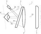
- FIG. 1 is a side cross-sectional view of a VR helmet provided by one of the exemplary embodiments of the present application.
- FIG. 2 is a side cross-sectional view of a VR helmet provided by an exemplary embodiment of the present application.
- FIG 3 is a side cross-sectional view of a VR helmet provided by an exemplary embodiment of the present application.
- FIGS. 4-6 are side cross-sectional views of a VR helmet provided by an exemplary embodiment of the present application.
- FIG. 7 is a schematic diagram of controlling an angle of a camera according to an exemplary embodiment of the present application.
- FIG. 8 is a schematic diagram of assembling a semi-reverse half lens sheet and a convex lens through a protective frame according to an exemplary embodiment of the present application.
- the VR helmet may include: a device body 1 in which a convex lens 2 and a VR playback component 5 are mounted; further, the device body 1 is further equipped with a half-reverse half for reflecting infrared light.
- the VR display content played by the VR playback component 5 can still be based on the form of the visible light S1 and is almost unaffected
- the visible light S1 is received by the user's eye 6 and the viewing of the VR display content is realized, and the infrared light S2 emitted by the user's eye 6 is mostly or almost completely
- the anti-half lens sheet 3 is reflected, and the corresponding reflected infrared light S2' is collected by the camera 4 mounted in the apparatus body 1, and the reflected infrared light S2' can be formed into an infrared image of
- the mirror surface 30 of the half-reflex lens sheet 3 is disposed obliquely, and the position between the half-reflex lens sheet 3 and the camera 4 is matched, so that the mirror surface 30 of the half-reflex lens sheet 3 can be used for the eye portion 6.
- the infrared light S2 corresponding to the infrared image of the eye is obliquely reflected toward the camera 4; for example, in the embodiment shown in FIG. 1, the camera 4 may be located near the user side of the device body 1 (ie, the left side in FIG. 1). At the lower edge, the lens of the camera 4 faces inward toward the semi-refractive lens sheet 3 to collect the reflected infrared light S2' described above.
- the angle ⁇ is maintained between the camera 4 and the infrared light S2, but since the mirror surface 30 of the half-reflex lens sheet 3 is inclined, the infrared light S2 is reflected toward the camera 4 to form the reflected infrared light S2', so that the camera 4 is
- the angle ⁇ between the reflected infrared light S2' and the reflected infrared light S2' is inevitably smaller than the above-mentioned angle ⁇ , thereby reducing the deformation and distortion that may occur in the infrared image of the eye collected by the camera 4, thereby contributing to the lifting of the eye to the eye 6.
- the accuracy of the infrared image acquisition and further improve the accuracy and accuracy of subsequent processing such as iris recognition and eye tracking.
- the visible range formed between the eye portion 6 and the convex lens 2 appears as a trapezoidal region shown in FIG. 1 (the trapezoidal cross section is actually; in fact, since the convex lens 2 is a circle Therefore, the top surface and the bottom surface of the apparatus body 1 are planar, and the camera 4 is located at the inner side edge of the bottom surface of the apparatus body 1, for example, the closer to the convex lens 2 The smaller the assembly space left for the camera 4, the larger the assembly space left to the camera 4 as it approaches the eye 6, so that when the camera 4 is assembled close to the eye 6 (i.e., the embodiment shown in Fig.
- the VR helmet can be an integrated VR headset device, that is, when the VR helmet can independently implement the VR play function without using an external device, the VR play component 5 is pre-built in the VR helmet.
- the VR playback component 5 can implement a rendering function such as rendering processing and display of the VR display content; or the VR helmet can be a split VR headset device, for example, when the VR helmet device cooperates with a mobile device such as a mobile phone or a tablet,
- the VR playback component 5 can include a mobile device mounted in the VR helmet, the mobile device can implement rendering processing through a processor, a graphics card chip, etc., display content through a screen component, etc., for example, when the VR helmet and the PC host, the game console
- the VR play component 5 may be a display component or the like built in the VR helmet, and the above external device is used to implement rendering processing of the VR display content.
- the half-reflex lens sheet 3 for reflecting infrared light refers to a lens having low transmittance for infrared spectrum and high transmittance for other spectra such as visible light, by shielding as much as possible
- the low-infrared infrared spectrum causes the half-reflex lens sheet 3 to reflect the infrared spectrum, that is, "semi-reverse"; at the same time, other spectra such as high-transmittance visible light can penetrate the half as much as possible
- the reverse half lens sheet 3 minimizes the occlusion and influence of the half mirror half sheet 3 on other spectra such as visible light, that is, "semi-transparent".
- the above-described half-reflex lens sheet 3 for reflecting infrared light may be an infrared dichroic mirror so that the visible spectrum can be almost completely transmitted and the infrared spectrum can be almost completely reflected.
- an infrared reflective film such as a TiO2-Ag-TiO2 infrared reflective film or a ZnS-Ag-ZnS infrared reflective film can be plated on the surface of the optical lens with high light transmission (which can be almost completely transmitted through the visible spectrum).
- a lens such as the above-described infrared reflective film or the like can be directly used to form a lens based entirely on the material to form the infrared dichroic mirror.
- the present application installs the half-reflex lens sheet 3 in the virtual reality wearing device, and the mirror surface 30 of the half-reflex lens sheet 3 is inclined, which can affect the user's viewing of the virtual reality display content without affecting the user.
- the deviation angle of the camera 4 when acquiring the infrared image of the eye is reduced, thereby reducing the distortion and distortion of the infrared image of the eye, which helps to improve the eye.
- the accuracy of the acquisition of infrared images is possible to improve the eye.
- the overall tilting manner shown in FIG. 1 may be adopted; in other embodiments, other manners may also be adopted.
- the mirror surface 30 is inclined, for example, as shown in FIG. 2, when the half-reflex lens sheet 3 has a wedge-shaped cross section, the bottom surface of the half-reflex lens sheet 3 is in a vertical direction, and the mirror surface 30 is inclined, thereby contributing to reduction.
- the assembly difficulty of the half-reverse half lens sheet 3 does not require repeated adjustments of the assembly angle of the half-reflex lens sheet 3.
- the mirror surface 30 of the half-reflex lens sheet 3 is inclined obliquely downward, and the camera 4 is located at the bottom of the apparatus body 1, and When the lens of the camera 4 is disposed obliquely upward, the infrared image of the eye of the user's eye 6 can be acquired relatively completely, clearly and accurately under the same conditions; of course, if an embodiment such as that shown in Fig.
- the mirror surface 30 of the half-reflex lens half 3 is inclined obliquely upward, and the camera 4 is located at the top of the apparatus body 1, and the lens of the camera 4 is disposed obliquely downward, and an infrared image of the eye of the eye portion 6 can also be obtained.
- the half-reflex lens sheet 3 may adopt other structures.
- the half-reflex lens sheet 3 in FIG. 4 may include tilting respectively.
- the upper lens structure 3A and the lower lens structure 3B are disposed, and the joint of the upper lens structure 3A and the lower lens structure 3B faces the user (in the embodiment shown in FIG. 4, corresponding to the downward orientation of the upper lens structure 3A)
- the left side is inclined
- the upper side is inclined toward the right side
- the lower lens structure 3B is inclined upward toward the left side and downwardly toward the right side).
- the device body 1 is equipped with a first camera 4A and a second camera 4B.
- the first camera 4A is located at the top of the device body 1 and the lens of the first camera 4A is disposed obliquely downward to fit the upper lens structure.
- the second camera 4B is located at the bottom of the apparatus body 1 and the lens of the second camera 4B is disposed obliquely upward to fit the lower lens structure 3B.
- the user wearing the VR device may have different shapes and the like of the head, the face, the eye, and the like, and the VR device is uniformly manufactured by the manufacturer, when different users wear the same VR device,
- the positional relationship between the eye 6 and the half-reflex lens sheet 3 may be different.
- the eye 6 may not be located in the middle position of the apparatus body 1 shown in FIG. 1-3, etc., which may cause the camera 4 to fail.
- the infrared image of the user's eye is completely captured.
- the present application can ensure that no matter what position change occurs in the eye portion 6 of the user, such as an upward shift or a downward shift, by adopting an embodiment such as that shown in FIG. A camera 4A and a second camera 4B completely collect corresponding eye infrared images.
- the upper region of the infrared image corresponding to the eye portion 6 corresponds to the first infrared ray S21
- the lower region corresponds to the first infrared ray S22
- the first infrared ray S21 can
- the first reflected infrared ray S21' is reflected by the upper mirror surface 30A of the upper lens structure 3A
- the first reflected infrared ray S21' is collected by the first camera 4A
- the second infrared ray S22 is reflected by the lower mirror surface 30B of the lower lens structure 3B.
- the second reflected infrared ray S22 ′ is obtained, and the second reflected infrared ray S22 ′ is collected by the second camera 4B, and then the first reflected infrared ray S21 ′ and the second reflected infrared ray S22 ′ can be combined to obtain an eye infrared corresponding to the eye 6 . image.
- the first infrared ray S21 and the first infrared ray S22 may both be emitted toward the upper lens structure 3A and reflected by the upper mirror surface 30A of the upper lens structure 3A.
- the first camera 4A combines the first reflected infrared ray S21 ′ and the second reflected infrared ray S22 ′ to obtain an infrared image of the eye corresponding to the eye portion 6 . .
- the first infrared ray S21 and the first infrared ray S22 may both be emitted toward the lower lens structure 3B and reflected by the upper mirror surface 30B of the lower lens structure 3B.
- the second camera 4B combines the first reflected infrared ray S21 ′ and the second reflected infrared ray S22 ′ to obtain an infrared image of the eye corresponding to the eye portion 6 . .
- the upper lens structure 3A and the lower lens structure 3B of the half-reflex lens sheet 3 shown in FIGS. 4-6 are symmetrical in a horizontal plane such that the upper lens structure 3A and the lower lens structure 3B have the same Or similar structural strength and stability, and the half-reflex lens sheet 3 has better overall stability.
- the upper lens structure 3A and the lower lens structure 3B may also adopt an asymmetric structure, such as a larger-sized lower lens structure 3B, to satisfy the infrared image of the eye in most cases. The acquisition is performed with a smaller-sized upper lens structure 3A to satisfy the collection of the infrared image of the eye in the case where the user's eye 6 is shifted upward in a small portion.
- the profiled half-reflex lens sheet 3 is adapted to different wearable users, and the present application provides other treatments.
- the virtual reality wearing device of the present application may further include an adjustment component 7 electrically connected to each camera 4, and the camera 4 may be angle-adjusted to keep the lens of the camera 4
- the virtual image formed in the semi-refractive lens sheet 3 toward the infrared image of the eye enables it to obtain a complete, clear and accurate eye infrared image.
- the virtual reality wearing device of the present application may further include the one shown in FIG.
- the protective frame 8 can form an accommodation space adapted to the half-reflex lens sheet 3 and the convex lens 2 to accommodate and fix the semi-reflex lens sheet 3 and the convex lens 2, thereby improving the integrity and stability of the structure. Sex.
- first, second, third, etc. may be used to describe various information in this application, such information should not be limited to these terms. These terms are only used to distinguish the same type of information from each other.
- first information may also be referred to as the second information without departing from the scope of the present application.
- second information may also be referred to as the first information.
- word "if” as used herein may be interpreted as "when” or “when” or “in response to a determination.”
Landscapes
- Physics & Mathematics (AREA)
- Engineering & Computer Science (AREA)
- General Physics & Mathematics (AREA)
- Optics & Photonics (AREA)
- General Engineering & Computer Science (AREA)
- Theoretical Computer Science (AREA)
- Human Computer Interaction (AREA)
- User Interface Of Digital Computer (AREA)
- Position Input By Displaying (AREA)
- Studio Devices (AREA)
Abstract
Description
Claims (10)
- 一种虚拟现实头戴设备,其特征在于,包括:设备本体,所述设备本体中装配有凸透镜;装配于所述设备本体中的摄像机和用于反射红外光的半反半透镜片,所述半反半透镜片位于所述凸透镜靠近用户的一侧,且所述半反半透镜片的镜面呈倾斜设置,以将用户的眼部红外图像朝向所述摄像机处进行斜向反射。
- 根据权利要求1所述的设备,其特征在于,所述半反半透镜片对可见光具有高透过率,且对红外光具有低透过率。
- 根据权利要求1所述的设备,其特征在于,所述半反半透镜片包括红外二向色镜。
- 根据权利要求1所述的设备,其特征在于,所述摄像机位于所述凸透镜相对于所述用户的可视范围之外。
- 根据权利要求1所述的设备,其特征在于,所述半反半透镜片呈片状;所述半反半透镜片的镜面朝向斜上方倾斜,所述摄像机位于所述设备本体的顶部,且所述摄像机的镜头朝向斜下方设置。
- 根据权利要求1所述的设备,其特征在于,所述半反半透镜片呈片状;所述半反半透镜片的镜面朝向斜下方倾斜,所述摄像机位于所述设备本体的底部,且所述摄像机的镜头朝向斜上方设置。
- 根据权利要求1所述的设备,其特征在于,所述半反半透镜片包括分别呈倾斜设置的上镜片结构和下镜片结构,且所述上镜片结构与所述下镜片结构的结合处朝向所述用户;所述设备本体中装配有第一摄像机和第二摄像机,所述第一摄像机位于所述设备本体的顶部且所述第一摄像机的镜头朝向斜下方设置,以配合于所述上镜片结构,所述第二摄像机位于所述设备本体的底部且所述第二摄像机的镜头朝向斜上方设置,以配合于所述下镜片结构。
- 根据权利要求7所述的设备,其特征在于,所述上镜片结构与所述下镜片结构沿水平平面对称。
- 根据权利要求1所述的设备,其特征在于,还包括:保护框,所述保护框形成适配于所述半反半透镜片与所述凸透镜的容纳空间,以对所述半反半透镜片与所述凸透镜进行容纳和固定。
- 根据权利要求1所述的设备,其特征在于,还包括:调节组件,所述调节组件可对所述摄像机进行角度调节,以使所述摄像机的镜头保持朝向所述眼部红外图像在所述半反半透镜片中形成的虚像。
Priority Applications (9)
| Application Number | Priority Date | Filing Date | Title |
|---|---|---|---|
| EP18758081.6A EP3557308B1 (en) | 2017-02-27 | 2018-02-26 | Virtual reality head-mounted apparatus |
| PH1/2019/501661A PH12019501661B1 (en) | 2017-02-27 | 2018-02-26 | Virtual reality head-mounted apparatus |
| SG11201906874WA SG11201906874WA (en) | 2017-02-27 | 2018-02-26 | Virtual reality head-mounted apparatus |
| ES18758081T ES2824820T3 (es) | 2017-02-27 | 2018-02-26 | Aparato de realidad virtual montado en la cabeza |
| KR1020197022644A KR102284974B1 (ko) | 2017-02-27 | 2018-02-26 | 가상현실용 머리-착용형 장치 |
| PL18758081T PL3557308T3 (pl) | 2017-02-27 | 2018-02-26 | Urządzenie wirtualnej rzeczywistości montowane na głowie |
| MYPI2019004078A MY193942A (en) | 2017-02-27 | 2018-02-26 | Virtual reality head-mounted apparatus |
| JP2019546360A JP6856863B2 (ja) | 2017-02-27 | 2018-02-26 | バーチャル・リアリティー・ヘッドマウント装置 |
| US16/511,353 US11442270B2 (en) | 2017-02-27 | 2019-07-15 | Virtual reality head-mounted apparatus with a partial-reflection partial-transmission wedge |
Applications Claiming Priority (2)
| Application Number | Priority Date | Filing Date | Title |
|---|---|---|---|
| CN201710109486.6 | 2017-02-27 | ||
| CN201710109486.6A CN106908951A (zh) | 2017-02-27 | 2017-02-27 | 虚拟现实头戴设备 |
Related Child Applications (1)
| Application Number | Title | Priority Date | Filing Date |
|---|---|---|---|
| US16/511,353 Continuation US11442270B2 (en) | 2017-02-27 | 2019-07-15 | Virtual reality head-mounted apparatus with a partial-reflection partial-transmission wedge |
Publications (1)
| Publication Number | Publication Date |
|---|---|
| WO2018153371A1 true WO2018153371A1 (zh) | 2018-08-30 |
Family
ID=59208362
Family Applications (1)
| Application Number | Title | Priority Date | Filing Date |
|---|---|---|---|
| PCT/CN2018/077285 Ceased WO2018153371A1 (zh) | 2017-02-27 | 2018-02-26 | 虚拟现实头戴设备 |
Country Status (12)
| Country | Link |
|---|---|
| US (1) | US11442270B2 (zh) |
| EP (1) | EP3557308B1 (zh) |
| JP (1) | JP6856863B2 (zh) |
| KR (1) | KR102284974B1 (zh) |
| CN (1) | CN106908951A (zh) |
| ES (1) | ES2824820T3 (zh) |
| MY (1) | MY193942A (zh) |
| PH (1) | PH12019501661B1 (zh) |
| PL (1) | PL3557308T3 (zh) |
| SG (1) | SG11201906874WA (zh) |
| TW (1) | TWI659229B (zh) |
| WO (1) | WO2018153371A1 (zh) |
Families Citing this family (8)
| Publication number | Priority date | Publication date | Assignee | Title |
|---|---|---|---|---|
| CN106908951A (zh) * | 2017-02-27 | 2017-06-30 | 阿里巴巴集团控股有限公司 | 虚拟现实头戴设备 |
| CN110850594B (zh) * | 2018-08-20 | 2022-05-17 | 余姚舜宇智能光学技术有限公司 | 头戴式可视设备及用于头戴式可视设备的眼球追踪系统 |
| US11442243B2 (en) | 2019-11-07 | 2022-09-13 | Htc Corporation | Head mounted display device |
| US20230316692A1 (en) * | 2020-09-14 | 2023-10-05 | Hewlett-Packard Development Company, L.P. | Head Mounted Display with Reflective Surface |
| CN116802632A (zh) * | 2020-09-25 | 2023-09-22 | 苹果公司 | 用于用户认证设备的系统和方法 |
| EP4202531A4 (en) | 2020-11-24 | 2024-03-20 | Samsung Electronics Co., Ltd. | AUGMENTED REALITY PORTABLE ELECTRONIC DEVICE WITH CAMERA |
| CN117310972A (zh) * | 2022-06-21 | 2023-12-29 | 北京七鑫易维信息技术有限公司 | 一种眼球追踪光学装置、系统和虚拟现实设备 |
| CN116719165A (zh) * | 2023-06-08 | 2023-09-08 | 业桓科技(成都)有限公司 | 头戴式显示器及近眼显示方法 |
Citations (9)
| Publication number | Priority date | Publication date | Assignee | Title |
|---|---|---|---|---|
| US6043799A (en) * | 1998-02-20 | 2000-03-28 | University Of Washington | Virtual retinal display with scanner array for generating multiple exit pupils |
| CN104407440A (zh) * | 2014-11-19 | 2015-03-11 | 东南大学 | 具有视线跟踪功能的全息显示装置 |
| CN105718046A (zh) * | 2014-12-23 | 2016-06-29 | 联发科技股份有限公司 | 用于眼部追踪的基于移动设备的头戴式显示器 |
| CN105955491A (zh) * | 2016-06-30 | 2016-09-21 | 北京上古视觉科技有限公司 | 一种具有眼控及虹膜识别功能的vr眼镜 |
| CN106214118A (zh) * | 2016-01-28 | 2016-12-14 | 北京爱生科贸有限公司 | 一种基于虚拟现实的眼球运动监测系统 |
| CN106406509A (zh) * | 2016-05-16 | 2017-02-15 | 上海青研科技有限公司 | 一种头戴式眼控虚拟现实设备 |
| CN106406543A (zh) * | 2016-11-23 | 2017-02-15 | 长春中国光学科学技术馆 | 人眼控制vr场景变换装置 |
| CN106908951A (zh) * | 2017-02-27 | 2017-06-30 | 阿里巴巴集团控股有限公司 | 虚拟现实头戴设备 |
| CN206584118U (zh) * | 2017-02-27 | 2017-10-24 | 阿里巴巴集团控股有限公司 | 虚拟现实头戴设备 |
Family Cites Families (67)
| Publication number | Priority date | Publication date | Assignee | Title |
|---|---|---|---|---|
| US4227113A (en) * | 1978-10-18 | 1980-10-07 | Duro-Test Corporation | Incandescent electric lamp with partial light transmitting coating |
| US5621424A (en) * | 1992-08-24 | 1997-04-15 | Olympus Optical Co., Ltd. | Head mount display apparatus allowing easy switching operation from electronic image to external field image |
| JPH06121254A (ja) * | 1992-10-06 | 1994-04-28 | Olympus Optical Co Ltd | 頭部装着式ディスプレイ装置 |
| US5347400A (en) | 1993-05-06 | 1994-09-13 | Ken Hunter | Optical system for virtual reality helmet |
| US6018630A (en) * | 1994-05-17 | 2000-01-25 | Canon Kabushiki Kaisha | Camera viewfinder having a viewpoint detecting apparatus |
| US7262919B1 (en) * | 1994-06-13 | 2007-08-28 | Canon Kabushiki Kaisha | Head-up display device with curved optical surface having total reflection |
| JP3309615B2 (ja) * | 1994-12-21 | 2002-07-29 | キヤノン株式会社 | 画像観察装置及びこれを用いた両眼画像観察装置 |
| JPH09274144A (ja) * | 1996-04-02 | 1997-10-21 | Canon Inc | 画像表示装置 |
| US5771124A (en) * | 1996-07-02 | 1998-06-23 | Siliscape | Compact display system with two stage magnification and immersed beam splitter |
| US5689619A (en) | 1996-08-09 | 1997-11-18 | The United States Of America As Represented By The Secretary Of The Army | Eyetracker control of heads-up displays |
| JPH11249588A (ja) * | 1998-02-27 | 1999-09-17 | Shimadzu Corp | 頭部装着型表示装置 |
| US6433760B1 (en) | 1999-01-14 | 2002-08-13 | University Of Central Florida | Head mounted display with eyetracking capability |
| WO2005111693A1 (ja) | 2004-05-17 | 2005-11-24 | Olympus Corporation | 頭部装着型画像表示装置 |
| CN101243392A (zh) | 2005-08-15 | 2008-08-13 | 皇家飞利浦电子股份有限公司 | 用于终端用户编程的增强现实眼镜的系统、设备和方法 |
| US7522344B1 (en) * | 2005-12-14 | 2009-04-21 | University Of Central Florida Research Foundation, Inc. | Projection-based head-mounted display with eye-tracking capabilities |
| CN200994790Y (zh) * | 2006-12-19 | 2007-12-26 | 潘晓刚 | 心理状态参数测试系统 |
| JP2008165063A (ja) | 2006-12-28 | 2008-07-17 | Scalar Corp | ヘッドマウントディスプレイ |
| CN101077232A (zh) * | 2007-06-07 | 2007-11-28 | 南京航空航天大学 | 一种用于穿戴式计算机的人机交互头盔 |
| JP5031452B2 (ja) * | 2007-06-20 | 2012-09-19 | キヤノン株式会社 | 画像観察装置及び画像観察システム |
| WO2009150747A1 (ja) * | 2008-06-13 | 2009-12-17 | パイオニア株式会社 | 視線入力によるユーザーインターフェース装置、ユーザーインターフェース方法、ユーザーインターフェースプログラム、及びユーザーインターフェースプログラムが記録された記録媒体 |
| JP5402293B2 (ja) | 2009-06-22 | 2014-01-29 | ソニー株式会社 | 頭部装着型ディスプレイ、及び、頭部装着型ディスプレイにおける画像表示方法 |
| US20120249797A1 (en) | 2010-02-28 | 2012-10-04 | Osterhout Group, Inc. | Head-worn adaptive display |
| US9285589B2 (en) | 2010-02-28 | 2016-03-15 | Microsoft Technology Licensing, Llc | AR glasses with event and sensor triggered control of AR eyepiece applications |
| US8482859B2 (en) | 2010-02-28 | 2013-07-09 | Osterhout Group, Inc. | See-through near-eye display glasses wherein image light is transmitted to and reflected from an optically flat film |
| US20120194418A1 (en) | 2010-02-28 | 2012-08-02 | Osterhout Group, Inc. | Ar glasses with user action control and event input based control of eyepiece application |
| WO2011106797A1 (en) | 2010-02-28 | 2011-09-01 | Osterhout Group, Inc. | Projection triggering through an external marker in an augmented reality eyepiece |
| CN202198569U (zh) * | 2011-08-09 | 2012-04-25 | 中国人民解放军空军航空医学研究所 | 一种侧反式眼动检测装置 |
| US9019614B2 (en) | 2011-10-26 | 2015-04-28 | Google Inc. | Display device with image depth simulation |
| JP6141584B2 (ja) * | 2012-01-24 | 2017-06-07 | アリゾナ ボード オブ リージェンツ オン ビハーフ オブ ザ ユニバーシティ オブ アリゾナ | 小型視線追従型ヘッドマウントディスプレイ |
| EP2808725B1 (en) | 2012-01-24 | 2018-09-26 | Sony Corporation | Head-mounted display device with a light-shielding member |
| US9788714B2 (en) | 2014-07-08 | 2017-10-17 | Iarmourholdings, Inc. | Systems and methods using virtual reality or augmented reality environments for the measurement and/or improvement of human vestibulo-ocular performance |
| US9737209B2 (en) * | 2013-05-15 | 2017-08-22 | The Johns Hopkins University | Eye tracking and gaze fixation detection systems, components and methods using polarized light |
| US9625723B2 (en) * | 2013-06-25 | 2017-04-18 | Microsoft Technology Licensing, Llc | Eye-tracking system using a freeform prism |
| EP2821839A1 (de) * | 2013-07-03 | 2015-01-07 | Airbus Defence and Space GmbH | HMD-Vorrichtung mit einstellbarer Eye-Tracking-Einrichtung |
| JP6175945B2 (ja) * | 2013-07-05 | 2017-08-09 | ソニー株式会社 | 視線検出装置及び視線検出方法 |
| US9494800B2 (en) * | 2014-01-21 | 2016-11-15 | Osterhout Group, Inc. | See-through computer display systems |
| US9330302B2 (en) * | 2014-02-26 | 2016-05-03 | Microsoft Technology Licensing, Llc | Polarized gaze tracking |
| KR20160143749A (ko) * | 2014-04-09 | 2016-12-14 | 쓰리엠 이노베이티브 프로퍼티즈 컴파니 | 머리 장착형 디스플레이 및 저 가시성 동공 조명기 |
| US9551873B2 (en) | 2014-05-30 | 2017-01-24 | Sony Interactive Entertainment America Llc | Head mounted device (HMD) system having interface with mobile computing device for rendering virtual reality content |
| US10445573B2 (en) * | 2014-06-27 | 2019-10-15 | Fove, Inc. | Gaze detection device |
| JP5824697B1 (ja) * | 2014-12-27 | 2015-11-25 | 株式会社Fove | ヘッドマウントディスプレイ |
| DK179537B1 (en) * | 2015-02-04 | 2019-02-08 | Itu Business Development A/S | Tin traces and eye tracking methods |
| KR101883090B1 (ko) * | 2015-04-01 | 2018-07-27 | 포브, 아이엔씨. | 헤드 마운트 디스플레이 |
| US9823474B2 (en) * | 2015-04-02 | 2017-11-21 | Avegant Corp. | System, apparatus, and method for displaying an image with a wider field of view |
| US20160378176A1 (en) * | 2015-06-24 | 2016-12-29 | Mediatek Inc. | Hand And Body Tracking With Mobile Device-Based Virtual Reality Head-Mounted Display |
| CN105093532A (zh) | 2015-08-03 | 2015-11-25 | 京东方科技集团股份有限公司 | 虚拟现实眼镜及显示方法 |
| CN205103761U (zh) * | 2015-08-03 | 2016-03-23 | 众景视界(北京)科技有限公司 | 头戴式智能设备 |
| CN205051824U (zh) | 2015-10-21 | 2016-02-24 | 北京小鸟看看科技有限公司 | 一种虚拟现实眼镜 |
| WO2017091477A1 (en) * | 2015-11-25 | 2017-06-01 | Google Inc. | Prism-based eye tracking |
| US9880384B2 (en) * | 2015-11-27 | 2018-01-30 | Fove, Inc. | Gaze detection system, gaze point detection method, and gaze point detection program |
| US10303246B2 (en) * | 2016-01-20 | 2019-05-28 | North Inc. | Systems, devices, and methods for proximity-based eye tracking |
| US10401952B2 (en) * | 2016-03-31 | 2019-09-03 | Sony Interactive Entertainment Inc. | Reducing rendering computation and power consumption by detecting saccades and blinks |
| US10192528B2 (en) * | 2016-03-31 | 2019-01-29 | Sony Interactive Entertainment Inc. | Real-time user adaptive foveated rendering |
| US10169846B2 (en) * | 2016-03-31 | 2019-01-01 | Sony Interactive Entertainment Inc. | Selective peripheral vision filtering in a foveated rendering system |
| CN205594581U (zh) * | 2016-04-06 | 2016-09-21 | 北京七鑫易维信息技术有限公司 | 视频眼镜的眼球追踪模组 |
| CN205721634U (zh) * | 2016-05-16 | 2016-11-23 | 上海青研科技有限公司 | 一种头戴式眼控虚拟现实设备 |
| CN205942608U (zh) * | 2016-06-30 | 2017-02-08 | 上海青研科技有限公司 | 一种用于眼球追踪和虹膜识别的一体化镜杯 |
| DE202016104179U1 (de) * | 2016-07-29 | 2016-08-12 | Christian Hildebrandt | Ausgabegerät zur stereoskopischen Bildwiedergabe |
| US20180068449A1 (en) * | 2016-09-07 | 2018-03-08 | Valve Corporation | Sensor fusion systems and methods for eye-tracking applications |
| US20180157320A1 (en) * | 2016-12-01 | 2018-06-07 | Oculus Vr, Llc | Air spaced optical assembly with integrated eye tracking |
| US10310598B2 (en) * | 2017-01-17 | 2019-06-04 | Facebook Technologies, Llc | Varifocal head-mounted display including modular air spaced optical assembly |
| US10485420B2 (en) * | 2017-02-17 | 2019-11-26 | Analog Devices Global Unlimited Company | Eye gaze tracking |
| US10546518B2 (en) * | 2017-05-15 | 2020-01-28 | Google Llc | Near-eye display with extended effective eyebox via eye tracking |
| US10627627B2 (en) * | 2017-10-02 | 2020-04-21 | Google Llc | Eye tracking using light guide with faceted combiner |
| US10788677B2 (en) * | 2017-10-03 | 2020-09-29 | Facebook Technologies, Llc | Fresnel assembly for light redirection in eye tracking systems |
| US10488917B2 (en) * | 2018-02-17 | 2019-11-26 | Varjo Technologies Oy | Gaze-tracking system and method of tracking user's gaze using reflective element |
| US10788892B2 (en) * | 2018-05-23 | 2020-09-29 | Facebook Technologies, Llc | In-field illumination and imaging for eye tracking |
-
2017
- 2017-02-27 CN CN201710109486.6A patent/CN106908951A/zh active Pending
- 2017-11-17 TW TW106139871A patent/TWI659229B/zh not_active IP Right Cessation
-
2018
- 2018-02-26 ES ES18758081T patent/ES2824820T3/es active Active
- 2018-02-26 MY MYPI2019004078A patent/MY193942A/en unknown
- 2018-02-26 EP EP18758081.6A patent/EP3557308B1/en active Active
- 2018-02-26 KR KR1020197022644A patent/KR102284974B1/ko active Active
- 2018-02-26 PH PH1/2019/501661A patent/PH12019501661B1/en unknown
- 2018-02-26 PL PL18758081T patent/PL3557308T3/pl unknown
- 2018-02-26 JP JP2019546360A patent/JP6856863B2/ja active Active
- 2018-02-26 WO PCT/CN2018/077285 patent/WO2018153371A1/zh not_active Ceased
- 2018-02-26 SG SG11201906874WA patent/SG11201906874WA/en unknown
-
2019
- 2019-07-15 US US16/511,353 patent/US11442270B2/en active Active
Patent Citations (9)
| Publication number | Priority date | Publication date | Assignee | Title |
|---|---|---|---|---|
| US6043799A (en) * | 1998-02-20 | 2000-03-28 | University Of Washington | Virtual retinal display with scanner array for generating multiple exit pupils |
| CN104407440A (zh) * | 2014-11-19 | 2015-03-11 | 东南大学 | 具有视线跟踪功能的全息显示装置 |
| CN105718046A (zh) * | 2014-12-23 | 2016-06-29 | 联发科技股份有限公司 | 用于眼部追踪的基于移动设备的头戴式显示器 |
| CN106214118A (zh) * | 2016-01-28 | 2016-12-14 | 北京爱生科贸有限公司 | 一种基于虚拟现实的眼球运动监测系统 |
| CN106406509A (zh) * | 2016-05-16 | 2017-02-15 | 上海青研科技有限公司 | 一种头戴式眼控虚拟现实设备 |
| CN105955491A (zh) * | 2016-06-30 | 2016-09-21 | 北京上古视觉科技有限公司 | 一种具有眼控及虹膜识别功能的vr眼镜 |
| CN106406543A (zh) * | 2016-11-23 | 2017-02-15 | 长春中国光学科学技术馆 | 人眼控制vr场景变换装置 |
| CN106908951A (zh) * | 2017-02-27 | 2017-06-30 | 阿里巴巴集团控股有限公司 | 虚拟现实头戴设备 |
| CN206584118U (zh) * | 2017-02-27 | 2017-10-24 | 阿里巴巴集团控股有限公司 | 虚拟现实头戴设备 |
Non-Patent Citations (1)
| Title |
|---|
| See also references of EP3557308A4 * |
Also Published As
| Publication number | Publication date |
|---|---|
| KR20190101445A (ko) | 2019-08-30 |
| PH12019501661A1 (en) | 2020-03-02 |
| KR102284974B1 (ko) | 2021-08-03 |
| US11442270B2 (en) | 2022-09-13 |
| EP3557308A1 (en) | 2019-10-23 |
| SG11201906874WA (en) | 2019-08-27 |
| US20190339527A1 (en) | 2019-11-07 |
| PL3557308T3 (pl) | 2021-01-25 |
| ES2824820T3 (es) | 2021-05-13 |
| JP6856863B2 (ja) | 2021-04-14 |
| MY193942A (en) | 2022-11-02 |
| EP3557308B1 (en) | 2020-08-26 |
| CN106908951A (zh) | 2017-06-30 |
| JP2020514887A (ja) | 2020-05-21 |
| PH12019501661B1 (en) | 2024-04-17 |
| EP3557308A4 (en) | 2020-01-29 |
| TWI659229B (zh) | 2019-05-11 |
| TW201831949A (zh) | 2018-09-01 |
Similar Documents
| Publication | Publication Date | Title |
|---|---|---|
| WO2018153371A1 (zh) | 虚拟现实头戴设备 | |
| CN206584118U (zh) | 虚拟现实头戴设备 | |
| US11500607B2 (en) | Using detected pupil location to align optical components of a head-mounted display | |
| WO2018153368A1 (zh) | 虚拟现实头戴设备 | |
| EP3516444B1 (en) | Eye tracking system | |
| US11269402B1 (en) | User interface interaction paradigms for eyewear device with limited field of view | |
| US9311536B2 (en) | Systems and methods for capturing artifact free images | |
| US9552060B2 (en) | Radial selection by vestibulo-ocular reflex fixation | |
| US20210026146A1 (en) | Optical assembly for head-mountable device | |
| US11726335B2 (en) | Head-mountable device with optical alignment | |
| US20130169683A1 (en) | Head mounted display with iris scan profiling | |
| US11774757B2 (en) | Optical module for head-mountable device | |
| WO2018153367A1 (zh) | 虚拟现实头戴设备 | |
| US20230319428A1 (en) | Camera comprising lens array | |
| CN206573783U (zh) | 虚拟现实头戴设备 | |
| JP2024520999A (ja) | 外部の視線検出による光漏れの低減 | |
| US12387636B2 (en) | Optical calibration | |
| HK1238346A1 (zh) | 虛擬現實頭戴設備 | |
| HK1238346A (zh) | 虚拟现实头戴设备 | |
| CN115802143A (zh) | 基于设备位置调整图像的显示 | |
| HK1238726A (zh) | 虛擬現實頭戴設備 | |
| HK1238726A1 (zh) | 虚拟现实头戴设备 |
Legal Events
| Date | Code | Title | Description |
|---|---|---|---|
| 121 | Ep: the epo has been informed by wipo that ep was designated in this application |
Ref document number: 18758081 Country of ref document: EP Kind code of ref document: A1 |
|
| ENP | Entry into the national phase |
Ref document number: 2018758081 Country of ref document: EP Effective date: 20190718 |
|
| ENP | Entry into the national phase |
Ref document number: 20197022644 Country of ref document: KR Kind code of ref document: A |
|
| ENP | Entry into the national phase |
Ref document number: 2019546360 Country of ref document: JP Kind code of ref document: A |
|
| NENP | Non-entry into the national phase |
Ref country code: DE |