WO2018154776A1 - モノセルの製造方法 - Google Patents
モノセルの製造方法 Download PDFInfo
- Publication number
- WO2018154776A1 WO2018154776A1 PCT/JP2017/007467 JP2017007467W WO2018154776A1 WO 2018154776 A1 WO2018154776 A1 WO 2018154776A1 JP 2017007467 W JP2017007467 W JP 2017007467W WO 2018154776 A1 WO2018154776 A1 WO 2018154776A1
- Authority
- WO
- WIPO (PCT)
- Prior art keywords
- electrode
- separator
- positive electrode
- negative electrode
- monocell
- Prior art date
- Legal status (The legal status is an assumption and is not a legal conclusion. Google has not performed a legal analysis and makes no representation as to the accuracy of the status listed.)
- Ceased
Links
Images



Classifications
-
- H—ELECTRICITY
- H01—ELECTRIC ELEMENTS
- H01M—PROCESSES OR MEANS, e.g. BATTERIES, FOR THE DIRECT CONVERSION OF CHEMICAL ENERGY INTO ELECTRICAL ENERGY
- H01M50/00—Constructional details or processes of manufacture of the non-active parts of electrochemical cells other than fuel cells, e.g. hybrid cells
- H01M50/40—Separators; Membranes; Diaphragms; Spacing elements inside cells
- H01M50/46—Separators, membranes or diaphragms characterised by their combination with electrodes
- H01M50/461—Separators, membranes or diaphragms characterised by their combination with electrodes with adhesive layers between electrodes and separators
-
- H—ELECTRICITY
- H01—ELECTRIC ELEMENTS
- H01M—PROCESSES OR MEANS, e.g. BATTERIES, FOR THE DIRECT CONVERSION OF CHEMICAL ENERGY INTO ELECTRICAL ENERGY
- H01M10/00—Secondary cells; Manufacture thereof
- H01M10/04—Construction or manufacture in general
- H01M10/0436—Small-sized flat cells or batteries for portable equipment
-
- H—ELECTRICITY
- H01—ELECTRIC ELEMENTS
- H01M—PROCESSES OR MEANS, e.g. BATTERIES, FOR THE DIRECT CONVERSION OF CHEMICAL ENERGY INTO ELECTRICAL ENERGY
- H01M10/00—Secondary cells; Manufacture thereof
- H01M10/04—Construction or manufacture in general
- H01M10/0404—Machines for assembling batteries
-
- H—ELECTRICITY
- H01—ELECTRIC ELEMENTS
- H01M—PROCESSES OR MEANS, e.g. BATTERIES, FOR THE DIRECT CONVERSION OF CHEMICAL ENERGY INTO ELECTRICAL ENERGY
- H01M10/00—Secondary cells; Manufacture thereof
- H01M10/04—Construction or manufacture in general
- H01M10/0413—Large-sized flat cells or batteries for motive or stationary systems with plate-like electrodes
-
- H—ELECTRICITY
- H01—ELECTRIC ELEMENTS
- H01M—PROCESSES OR MEANS, e.g. BATTERIES, FOR THE DIRECT CONVERSION OF CHEMICAL ENERGY INTO ELECTRICAL ENERGY
- H01M10/00—Secondary cells; Manufacture thereof
- H01M10/04—Construction or manufacture in general
- H01M10/0463—Cells or batteries with horizontal or inclined electrodes
-
- H—ELECTRICITY
- H01—ELECTRIC ELEMENTS
- H01M—PROCESSES OR MEANS, e.g. BATTERIES, FOR THE DIRECT CONVERSION OF CHEMICAL ENERGY INTO ELECTRICAL ENERGY
- H01M10/00—Secondary cells; Manufacture thereof
- H01M10/05—Accumulators with non-aqueous electrolyte
- H01M10/058—Construction or manufacture
- H01M10/0585—Construction or manufacture of accumulators having only flat construction elements, i.e. flat positive electrodes, flat negative electrodes and flat separators
-
- H—ELECTRICITY
- H01—ELECTRIC ELEMENTS
- H01M—PROCESSES OR MEANS, e.g. BATTERIES, FOR THE DIRECT CONVERSION OF CHEMICAL ENERGY INTO ELECTRICAL ENERGY
- H01M50/00—Constructional details or processes of manufacture of the non-active parts of electrochemical cells other than fuel cells, e.g. hybrid cells
- H01M50/40—Separators; Membranes; Diaphragms; Spacing elements inside cells
- H01M50/46—Separators, membranes or diaphragms characterised by their combination with electrodes
-
- H—ELECTRICITY
- H01—ELECTRIC ELEMENTS
- H01M—PROCESSES OR MEANS, e.g. BATTERIES, FOR THE DIRECT CONVERSION OF CHEMICAL ENERGY INTO ELECTRICAL ENERGY
- H01M10/00—Secondary cells; Manufacture thereof
- H01M10/05—Accumulators with non-aqueous electrolyte
- H01M10/052—Li-accumulators
-
- H—ELECTRICITY
- H01—ELECTRIC ELEMENTS
- H01M—PROCESSES OR MEANS, e.g. BATTERIES, FOR THE DIRECT CONVERSION OF CHEMICAL ENERGY INTO ELECTRICAL ENERGY
- H01M4/00—Electrodes
- H01M4/02—Electrodes composed of, or comprising, active material
- H01M2004/026—Electrodes composed of, or comprising, active material characterised by the polarity
- H01M2004/028—Positive electrodes
-
- Y—GENERAL TAGGING OF NEW TECHNOLOGICAL DEVELOPMENTS; GENERAL TAGGING OF CROSS-SECTIONAL TECHNOLOGIES SPANNING OVER SEVERAL SECTIONS OF THE IPC; TECHNICAL SUBJECTS COVERED BY FORMER USPC CROSS-REFERENCE ART COLLECTIONS [XRACs] AND DIGESTS
- Y02—TECHNOLOGIES OR APPLICATIONS FOR MITIGATION OR ADAPTATION AGAINST CLIMATE CHANGE
- Y02E—REDUCTION OF GREENHOUSE GAS [GHG] EMISSIONS, RELATED TO ENERGY GENERATION, TRANSMISSION OR DISTRIBUTION
- Y02E60/00—Enabling technologies; Technologies with a potential or indirect contribution to GHG emissions mitigation
- Y02E60/10—Energy storage using batteries
-
- Y—GENERAL TAGGING OF NEW TECHNOLOGICAL DEVELOPMENTS; GENERAL TAGGING OF CROSS-SECTIONAL TECHNOLOGIES SPANNING OVER SEVERAL SECTIONS OF THE IPC; TECHNICAL SUBJECTS COVERED BY FORMER USPC CROSS-REFERENCE ART COLLECTIONS [XRACs] AND DIGESTS
- Y02—TECHNOLOGIES OR APPLICATIONS FOR MITIGATION OR ADAPTATION AGAINST CLIMATE CHANGE
- Y02P—CLIMATE CHANGE MITIGATION TECHNOLOGIES IN THE PRODUCTION OR PROCESSING OF GOODS
- Y02P70/00—Climate change mitigation technologies in the production process for final industrial or consumer products
- Y02P70/50—Manufacturing or production processes characterised by the final manufactured product
Definitions
- the present invention relates to a method for producing a monocell formed by alternately laminating separators and electrodes.
- Patent Document 1 discloses a method of manufacturing a basic laminate that constitutes an electrode laminate used for a secondary battery.
- the basic laminate is formed by laminating a pair of electrodes each cut into a predetermined shape on a pair of long and continuous separators, joining these four members together, and then using a cutter to form a pair. These separators are simultaneously cut.
- the first electrode is sequentially joined to one surface of the strip-shaped first separator, and the second electrode having a different size from the first electrode is sequentially joined to the other surface.
- the band-shaped second separator is bonded to one of the first electrode and the second electrode.
- the position of the first electrode is detected upstream or downstream of the junction point of the second electrode, and the second electrode is joined to the first separator on the basis of the detected position of the first electrode. Correct the joining position.
- the first electrode in order to adjust the joining position of the second electrode with reference to the position of the first electrode, the first electrode can be used even when a pair of electrodes are stacked via a strip-shaped separator. Therefore, the second electrode can be accurately aligned, and variations in the relative positions of the first electrode and the second electrode can be suppressed.
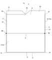
- the perspective view of the electrode lamination apparatus of one Example The exploded perspective view of a monocell. Explanatory drawing which shows the detection position of the positive electrode and negative electrode by a joining position detection camera. The perspective view of a positive electrode alignment mechanism.
- FIG. 1 schematically shows an electrode stacking apparatus 2 that continuously manufactures monocells 1 as a basic stack
- FIG. 2 schematically shows a monocell 1 manufactured by the electrode stacking apparatus 2.
- the monocell 1 and the electrode stacking device 2 are referred to as “upper” and “lower” with reference to the postures of FIGS.
- the monocell 1 includes, in order from the top, a sheet-like separator 4, a sheet-like positive electrode 6 that is an electrode, a sheet-like separator 8, and a sheet-like negative electrode 10 that is an electrode. These are joined together to form a four-layer structure.
- the positive electrode 6 is formed in a sheet shape by binding an active material layer on both surfaces of a current collector made of, for example, aluminum.
- the positive electrode 6 has a pair of long edges 12 and 13 along the long side of the quadrangle and a pair of short edges 14 and 15 along the short side, and partially protrudes from the short edge 14. It has a positive electrode tab 16.
- the positive electrode tab 16 is offset to one side, and the side edge is continuous with the one long edge portion 12.
- the negative electrode 10 is formed in a sheet shape by binding an active material layer on both surfaces of a current collector made of, for example, copper.
- the dimension of the negative electrode 10 is slightly larger than the dimension of the positive electrode 6.
- the negative electrode 10 has a pair of long edges 18 and 19 along the long side of the quadrangle and a pair of short edges 20 and 21 along the short side, and partially protrudes from the short edge 20. It has a negative electrode tab 22.
- the negative electrode tab 22 is offset to the opposite side to the positive electrode tab 16, and the side edge is continuous with the long edge portion 19.
- the separators 4 and 8 function to electrically isolate the positive electrode 6 and the negative electrode 10 and to hold an electrolyte solution between the positive electrode 6 and the negative electrode 10.
- the separators 4 and 8 have the same configuration, and are formed in a rectangular sheet shape from, for example, a synthetic resin such as polyethylene or polypropylene.
- the dimensions of the separators 4 and 8 are slightly larger than the dimensions of the rectangular portion of the negative electrode 10 excluding the negative electrode tab 22.
- An electrode stack that is, a power generation element is formed by stacking a plurality of monocells 1 formed in this way.
- the electrode laminate is housed in an outer package made of a laminate film together with an electrolytic solution to form a film outer battery.
- an electrode stacking apparatus 2 that continuously manufactures monocells 1 has an adsorption drum for a negative electrode 10 that is provided so as to face each other with a separator 8 that is long and continuous in the longitudinal direction of the apparatus 2. 28 and a nip roller 30.
- a negative electrode dispenser 32 is disposed so as to face the suction drum 28. The negative electrode dispenser 32 applies the adhesive in a dotted manner to the upper surface 10a of the negative electrode 10 that is conveyed to the device 2 through the negative electrode conveyance path L1 in a state of being cut into a predetermined shape in advance.
- the suction drum 28 sucks and conveys the negative electrode 10, and sequentially stacks the negative electrode 10 on the lower surface 8 b of the separator 8.
- the nip roller 30 presses the negative electrode 10 and the separator 8 stacked on each other against the suction drum 28, whereby the negative electrode 10 is joined to the separator 8.
- the first positive electrode dispenser 42 applies an adhesive in a dotted manner to the lower surface 6b of the positive electrode 6 that is conveyed to the device 2 through the positive electrode conveyance path L2 in a state of being cut into a predetermined shape in advance.
- the suction drum 38 sucks and conveys the positive electrode 6 and sequentially stacks the positive electrode 6 on the upper surface 8 a of the separator 8 so as to correspond to the position of the negative electrode 10 joined to the lower surface 8 b of the separator 8.
- the nip roller 40 presses the negative electrode 10, the separator 8, and the positive electrode 6 stacked on each other against the suction drum 38, whereby the positive electrode 6 is joined to the upper surface 8 a of the separator 8.
- the second dispenser for positive electrode 44 applies an adhesive to the upper surface 6 a of the positive electrode 6 joined to the separator 8 in the form of dots.
- a conveying roller 52 and a nip roller 54 are provided on the downstream side of the nip roller 40, and the separator 4 continuous in a belt shape is supplied to the upper surface 6 a of the positive electrode 6 via the nip roller 54.
- the negative electrode 10, the separator 8, the positive electrode 6, and the separator 4 are stacked.
- the lower surface 4 a of the separator 4 is bonded to the positive electrode 6 by the adhesive supplied by the second dispenser 44 for positive electrode.
- a cutter 56 is provided on the downstream side of the nip roller 54.
- the cutter 56 simultaneously cuts the separators 4 and 8 between the adjacent negative electrodes 10 and 10. Thereby, the monocell 1 having a predetermined dimension is formed.
- the positive electrode 6 and the negative electrode 10 are conveyed in a posture in which the positive electrode tab 16 and the negative electrode tab 22 face sideways with respect to the separator conveyance direction Ts.
- two positive electrode bonding position detection cameras 61 and 62 that are located above the positive electrode 6 bonded to the strip-shaped separator 8 and detect the bonding position of the positive electrode 6, and Two negative electrode bonding position detection cameras 63 and 64 are provided below the negative electrode 10 bonded to the strip-shaped separator 8 and detect the bonding position of the negative electrode 10.
- the junction position detection cameras 61 and 62 for positive electrodes have substantially the same configuration, and are arranged at positions aligned along the width direction of the separator 8.
- One camera 61 is disposed on one short edge portion 14 side of the positive electrode 6, and the other camera 62 is disposed on the other short edge portion 15 side.
- the cameras 61 and 62 photograph the positive electrode 6 from above while the positive electrode 6 is being transported along the separator transport direction Ts, and detect the position of the positive electrode 6 that is joined to the separator 8.
- the negative electrode joint position detection cameras 63 and 64 have substantially the same configuration as the positive electrode joint position detection cameras 61 and 62, and are arranged at positions aligned in the width direction of the separator 8. Has been. One camera 63 is disposed on one short edge portion 20 side of the negative electrode 10, and the other camera 64 is disposed on the other short edge portion 21 side.
- the negative electrode joining position detection cameras 63 and 64 photograph the negative electrode 10 from below while the negative electrode 10 is being transported along the separator transport direction Ts, and detect the relative joint position of the negative electrode 10 with respect to the separator 8.
- FIG. 3 shows the detection positions of the positive electrode 6 and the negative electrode 10 by the positive electrode bonding position detection cameras 61 and 62 and the negative electrode bonding position detection cameras 63 and 64.
- the separator 8 is not shown.
- the positive electrode 6 is stacked above the negative electrode 10 via a separator 8 (not shown), and the relatively large negative electrode 10 slightly protrudes from the periphery of the positive electrode 6.
- the long edge 12 on the upstream side with respect to the separator transport direction Ts is defined as “upstream long edge”, and the long edge 13 on the downstream side is defined as “downstream”.
- the “long side edge”, the short edge 14 on the left side with respect to the separator transport direction Ts are defined as the “left short edge”, and the short edge 15 on the right side is defined as the “right short edge”.
- the long edge 18 on the upstream side with respect to the separator transport direction Ts is the “upstream long edge”
- the long edge 19 on the downstream is the “downstream long edge”
- the separator transport The short edge 20 on the left side with respect to the direction Ts is defined as a “left short edge”
- the short edge 21 on the right side is defined as a “right short edge”.
- the positive electrode joint position detection cameras 61 and 62 detect two points P1 and P2 along the downstream long edge 13 of the positive electrode 6 on the side opposite to the positive electrode tab 16, respectively. Specifically, a point P1 that is a vertex of the corner constituted by the downstream long edge 13 and the left short edge 14 is detected by the camera 61, and the downstream long edge 13 and the right short edge 15 are detected. A point P2 that is the vertex of the constructed corner is detected by the camera 62. These points P1 and P2 serve as a position reference for the positive electrode 6.
- the negative electrode joint position detection cameras 63 and 64 detect two points P3 and P4 along the upstream long edge 18 of the negative electrode 10 on the opposite side to the negative electrode tab 22. Specifically, a point P3 that is the apex of the corner constituted by the upstream long edge 18 and the left short edge 20 is detected by the camera 63, and the upstream long edge 18 and the right short edge 21 are detected. A point P4 that is the vertex of the constructed corner is detected by the camera 64. These points P3 and P4 serve as a position reference for the negative electrode 10.
- the positive junction position detection cameras 61 and 62 and the negative junction position detection cameras 63 and 64 transmit detection data to a control device (not shown).
- the control device determines the tendency of the joining position of the positive electrode 6 and the tendency of the joining position of the negative electrode 10 based on the detection data transmitted from the cameras 61 to 64, respectively.
- the positive electrode transport position detection cameras 71 and 72 photograph the positive electrode 6 during transport of the positive electrode 6 along the positive electrode transport direction Tp, and detect the transport position of the positive electrode 6 during this transport. Specifically, the positive electrode conveyance position detection cameras 71 and 72 detect the two corner points P1 and P2 of the downstream long edge portion 13 in the same manner as the positive electrode joining position detection cameras 61 and 62, respectively.
- FIG. 4 shows the positive electrode alignment mechanism 74.
- the positive electrode alignment mechanism 74 conveys the positive electrode 6 that has passed through the positive electrode conveyance position detection cameras 71 and 72 toward the electrode laminating apparatus 2, and joins the positive electrode 6 to the conveyance position of the positive electrode 6, that is, the separator 8 during this conveyance.
- the bonding position at that time (hereinafter also referred to as the bonding position of the positive electrode 6) is corrected.
- the positive electrode alignment mechanism 74 is feedback controlled by a control device (not shown). That is, the positive electrode alignment mechanism 74 corrects the bonding position of the positive electrode 6 so as to match the tendency of the bonding position of the negative electrode 10 with respect to the separator 8 determined by the control device.
- the positive electrode alignment mechanism 74 sets the transport direction position X along the positive electrode transport direction Tp of the positive electrode 6, the width direction position Y orthogonal to the positive electrode transport direction Tp of the positive electrode 6, and the inclination Z of the positive electrode 6. to correct.
- the conveyance direction position X of the positive electrode 6 is corrected by adjusting the conveyance speed of the positive electrode 6.
- the position Y in the width direction of the positive electrode 6 is corrected by the positive electrode alignment mechanism 74 moving to the left short edge portion 14 side or the right short edge portion 15 side of the positive electrode 6.
- the inclination Z of the positive electrode 6 is corrected by making the conveyance speed on the left short edge portion 14 side and the conveyance speed on the right short edge portion 15 side of the positive electrode 6 different.
- two negative electrode conveyance position detection cameras 76 and 77 that detect the position of the negative electrode 10 during conveyance and two negative electrode conveyance position detection cameras 76 and 77 are disposed in the negative electrode conveyance path L1.
- a negative electrode alignment mechanism 78 located on the downstream side.
- the negative electrode conveyance position detection cameras 76 and 77 photograph the negative electrode 10 during conveyance of the negative electrode 10 along the negative electrode conveyance direction Tn, and detect the conveyance position of the negative electrode 10 during this conveyance. Specifically, the negative electrode conveyance position detection cameras 76 and 77 detect the two points P3 and P4 at the corners of the upstream long edge 18 of the negative electrode 10, respectively, similarly to the negative electrode joining position detection cameras 63 and 64. .
- the negative electrode alignment mechanism 78 transports the negative electrode 10 that has passed through the negative electrode transport position detection cameras 76 and 77 toward the apparatus 2 and corrects the transport position of the negative electrode 10, that is, the joining position of the negative electrode 10 to the separator 8 during the transport. To do.
- the negative electrode alignment mechanism 78 corrects the joining position of the negative electrode 10 so as to match the reference position on the equipment side.
- the negative electrode alignment mechanism 78 corrects the transport direction position along the negative electrode transport direction Tn of the negative electrode 10, the width direction position of the negative electrode 10 orthogonal to the negative electrode transport direction Tn, and the inclination of the negative electrode 10, respectively. .
- two cutting position detection cameras 81 and 82 arranged below the negative electrode 10 are provided on the downstream side of the conveying roller 52 and the upstream side of the cutter 56.
- the cameras 81 and 82 have substantially the same configuration and are arranged at positions aligned along the width direction of the separator 8.
- Cameras 81 and 82 photograph the negative electrode 10 from below while the negative electrode 10, the separator 8, the positive electrode 6, and the separator 4 are joined to each other, and then the negative electrode 10 is conveyed along the separator conveyance direction Ts. 8, the bonding position of each negative electrode 10 with respect to 8 is detected.
- the cameras 81 and 82 detect the two points P3 and P4 at the corners of the upstream long edge 18 of the negative electrode 10, respectively, similarly to the negative electrode joint position detection cameras 63 and 64. Detection results by the cameras 63 and 64 are used to correct the cutting position by the cutter 56.
- the negative electrode 10 is conveyed along the negative electrode conveyance direction Tn, and joined to the lower surface 8b of the separator 8 so as to be aligned with the reference position on the equipment side.
- the positive electrode 6 is conveyed along the positive electrode conveyance direction Tp, and after the conveyance positions of the positive electrode 6 being conveyed, that is, the points P1 and P2 are detected by the positive electrode conveyance position detection cameras 71 and 72, the upper surface 8a of the separator 8 is detected. Are sequentially stacked.
- the bonding position of the positive electrode 6, that is, the points P 1 and P 2 are detected by the positive electrode bonding position detection cameras 61 and 62, and the bonding position of the negative electrode 10, that is, the point P 3. P4 is detected by the negative electrode joining position detection cameras 63 and 64.
- the cameras 61, 62, 63, and 64 transmit detection data to a control device (not shown).
- the control device Based on the transmitted detection data, the control device obtains the tendency of the joining position of the negative electrode 10 and the tendency of the joining position of the positive electrode 6 sequentially joined to the strip-shaped separator 8, and the tendency of the joining position of the positive electrode 6. Is consistent with the tendency of the joining position of the negative electrode 10.
- the control device When the tendency of the joining position of the positive electrode 6 is not consistent with the tendency of the joining position of the negative electrode 10, that is, when a positional deviation occurs between the negative electrode 10 and the positive electrode 6, the control device The positions of the points P1 and P2 of the positive electrode 6 at the time of joining detected by the detection cameras 61 and 62, and the positions of the points P1 and P2 of the positive electrode 6 before joining detected by the positive electrode transport position detection cameras 71 and 72; Are compared, the correction amount of the joining position of the positive electrode 6 is determined, and the result is fed back to the positive electrode alignment mechanism 74.
- the positive electrode alignment mechanism 74 corrects the bonding position of the positive electrode 6 during conveyance of the positive electrode 6 along the positive electrode conveyance direction Tp so as to match the tendency of the bonding position of the negative electrode 10 based on feedback from the control device.
- the negative electrode 10 tends to be joined to the separator 8 by being shifted to the upstream side or the downstream side in the separator transport direction Ts from the reference position on the equipment side, and the tendency of the negative electrode 10 and the joining position of the positive electrode 6 Are not aligned, that is, when the negative electrode 10 and the positive electrode 6 are misaligned in the separator conveyance direction Ts, the positive electrode alignment mechanism 74 conveys the positive electrode 6 so as to be aligned with the position of the negative electrode 10. The direction position X is corrected.
- the positional deviation in the separator transport direction Ts between the negative electrode 10 and the positive electrode 6 is determined by the distance between the two points P3 and P4 of the negative electrode 10 and the two points P1 and P2 of the positive electrode 6. Specifically, as shown in FIG. 3, it is determined whether the distance D between the midpoint M1 between the points P1 and P2 and the midpoint M2 between the points P3 and P4 is within a reference value. To do. When the distance D between the midpoint M1 and the midpoint M2 is larger than the reference value, the positive electrode alignment mechanism 74 corrects the transport direction position X of the positive electrode 6 by increasing the transport speed of the positive electrode 6.
- the positive electrode alignment mechanism 74 corrects the transport direction position X of the positive electrode 6 by slowing the transport speed of the positive electrode 6. In this way, by correcting the position X in the transport direction of the positive electrode 6, the positive electrode 6 is disposed at the approximate center of the relatively slightly larger negative electrode 10.
- the positive electrode alignment mechanism 74 corrects the width direction position Y of the positive electrode 6 so as to be aligned with the position of the negative electrode 10.
- the positional deviation in the width direction between the negative electrode 10 and the positive electrode 6 is determined by the position of the point P1 of the positive electrode 6 with respect to the point P3 of the negative electrode 10 and the position of the point P2 of the positive electrode 6 with respect to the point P4 of the negative electrode 10.
- the positive electrode alignment mechanism 74 moves in the width direction toward the left short edge portion 14 side.
- the position Y in the width direction is corrected.
- the positive electrode alignment mechanism 74 moves in the width direction to the right short edge portion 15 side,
- the width direction position Y of the positive electrode 6 is corrected.
- the positive electrode alignment mechanism 74 follows the inclination of the negative electrode 10.
- the inclination Z of the positive electrode 6 is corrected so as to be matched.
- the deviation between the inclination of the negative electrode 10 and the inclination of the positive electrode 6 is the inclination of the points 1 and P2 of the positive electrode 6 with respect to the points P3 and P4 of the negative electrode 10, that is, the downstream long edge of the positive electrode 6 with respect to the upstream long edge 18 of the negative electrode 10. It is judged by the inclination of 13.
- the positive electrode alignment mechanism 74 corrects the inclination Z of the positive electrode 6 by changing the conveyance speed on the left short edge portion 14 side and the conveyance speed on the right short edge portion 15 side in the positive electrode 6. In this way, by correcting the inclination Z of the positive electrode 6, the edges 12, 13, 14, and 15 of the positive electrode 6 are substantially parallel to the edges 18, 19, 20, and 21 of the negative electrode 10.
- the bonding position of the positive electrode 6 at the time of bonding to the separator 8 is corrected with the bonding position of the negative electrode 10 as a reference, and the positive electrode 6 is bonded to the separator 8, whereby the negative electrode 10 is interposed via the strip-shaped separator 8. Even when the positive electrode 6 and the positive electrode 6 are stacked on each other, the position of the negative electrode 10 and the position of the positive electrode 6 can be aligned, and variations in the relative positions of the negative electrode 10 and the positive electrode 6 can be suppressed.
- the position of the negative electrode 10 can be corrected by the negative electrode alignment mechanism 78 when the negative electrode 10 conveyed along the negative electrode conveyance direction Tn is not aligned with the reference position on the equipment side. is there.
- the position of the negative electrode 10 relative to the separator 8 is detected on the downstream side of the junction point of the positive electrode 6, but the position of the negative electrode 10 relative to the separator 8 is detected on the upstream side of the junction point of the positive electrode 6. Also good.
- the positions where the positive electrode 6 is actually bonded that is, the points P1 and P2 are detected together with the positions of the negative electrode 10, that is, the points P3 and P4, and the consistency between the two is judged to correct the bonding position of the positive electrode 6.
- the joining position of the positive electrode 6 may be corrected based on the detection position of the negative electrode 10 without detecting the final joining position of the positive electrode 6.
- the monocell 1 is formed as a four-layer structure including the separator 4, the positive electrode 6, the separator 8, and the negative electrode 10.
- the monocell 1 is formed as a four-layer structure including the separator 4, the positive electrode 6, the separator 8, and the negative electrode 10.
- a monocell having a three-layer structure can be applied to the present invention. .
Landscapes
- Chemical & Material Sciences (AREA)
- Chemical Kinetics & Catalysis (AREA)
- Electrochemistry (AREA)
- General Chemical & Material Sciences (AREA)
- Engineering & Computer Science (AREA)
- Manufacturing & Machinery (AREA)
- Secondary Cells (AREA)
- Connection Of Batteries Or Terminals (AREA)
Abstract
Description
Claims (8)
- セパレータおよび電極を交互に積層してなるモノセルの製造方法であって、
連続して搬送された帯状の第1のセパレータの一方の面に、所定の形状に裁断された第1の電極を順次接合し、上記第1のセパレータの他方の面に所定の形状に裁断された第1の電極とは大きさの異なる第2の電極を順次接合し、上記第1の電極および上記第2の電極の一方に、連続して搬送された帯状の第2のセパレータを接合し、隣接する第1の電極の間で上記第1のセパレータおよび上記第2のセパレータを重ねて切断する製造方法において、
上記第2の電極の接合点の上流側または下流側において上記第1の電極の位置を検出し、この検出した第1の電極の位置を基準として、上記第1のセパレータに上記第2の電極を接合する際の接合位置を補正する、モノセルの製造方法。 - 上記第1の電極の位置の検出は、上記第1の電極の搬送方向上流側の縁部または下流側の縁部に沿った2点を検出することにより行われる、請求項1に記載のモノセルの製造方法。
- 上記第1の電極は、当該第1の電極の搬送方向に対し側方へ部分的に突出したタブを有し、このタブが上記上流側の縁部または上記下流側の縁部の一方に連続しており、
上記第1の電極の位置の検出は、上記タブと反対側となる上記上流側縁部または上記下流側縁部の角の2点を検出することにより行われる、請求項1または2に記載のモノセルの製造方法。 - 上記第1のセパレータの搬送方向に沿った方向に関して、上記第1の電極の位置に対応して、上記第2の電極の接合位置を補正する、請求項1~3のいずれかに記載のモノセルの製造方法。
- 上記第1のセパレータの搬送方向と直交する方向に関して、上記第1の電極の位置に対応して、上記第2の電極の接合位置を補正する、請求項1~4のいずれかに記載のモノセルの製造方法。
- 上記第1のセパレータに対する上記第1の電極の傾きに対応して、上記第1のセパレータに上記第2の電極を接合する際に、上記第1のセパレータに対する上記第2の電極の傾きを補正する、請求項1~5のいずれかに記載のモノセルの製造方法。
- 上記第1のセパレータに対する上記第1の電極の位置を検出し、この検出位置に基づいて、上記第1のセパレータおよび上記第2のセパレータの切断位置を補正する、請求項1~6のいずれかに記載のモノセルの製造方法。
- 帯状の第1のセパレータを連続して搬送する搬送装置と、
上記第1のセパレータの一方の面に、第1の電極を順次接合する第1の電極貼付部と、
上記第1の電極貼付部の下流側において、上記第1のセパレータの他方の面に上記第1の電極とは大きさの異なる第2の電極を順次接合する第2の電極貼付部と、
上記第2の電極貼付部の下流側において、上記第2の電極に重ねて帯状の第2のセパレータを供給するセパレータ供給部と、
上記セパレータ供給部の下流側で上記第1のセパレータおよび上記第2のセパレータを重ねて切断する切断部と、
上記第2の電極貼付部の上流側または下流側において上記第1の電極の位置を検出する位置検出部と、
この検出した第1の電極の位置を基準として、上記第2の電極貼付部において上記第1のセパレータに上記第2の電極を接合する際の接合位置を補正するアライメント機構と、
を備える、モノセル接合装置。
Priority Applications (6)
| Application Number | Priority Date | Filing Date | Title |
|---|---|---|---|
| PCT/JP2017/007467 WO2018154776A1 (ja) | 2017-02-27 | 2017-02-27 | モノセルの製造方法 |
| EP17897296.4A EP3588653B1 (en) | 2017-02-27 | 2017-02-27 | Method for producing mono-cell |
| KR1020197025857A KR102345220B1 (ko) | 2017-02-27 | 2017-02-27 | 모노 셀의 제조 방법 |
| JP2019501000A JP6700469B2 (ja) | 2017-02-27 | 2017-02-27 | モノセルの製造方法 |
| CN201780087525.5A CN110352521B (zh) | 2017-02-27 | 2017-02-27 | 单电池的制造方法和单电池接合装置 |
| US16/488,796 US11302994B2 (en) | 2017-02-27 | 2017-02-27 | Method for producing mono-cell |
Applications Claiming Priority (1)
| Application Number | Priority Date | Filing Date | Title |
|---|---|---|---|
| PCT/JP2017/007467 WO2018154776A1 (ja) | 2017-02-27 | 2017-02-27 | モノセルの製造方法 |
Publications (1)
| Publication Number | Publication Date |
|---|---|
| WO2018154776A1 true WO2018154776A1 (ja) | 2018-08-30 |
Family
ID=63252559
Family Applications (1)
| Application Number | Title | Priority Date | Filing Date |
|---|---|---|---|
| PCT/JP2017/007467 Ceased WO2018154776A1 (ja) | 2017-02-27 | 2017-02-27 | モノセルの製造方法 |
Country Status (6)
| Country | Link |
|---|---|
| US (1) | US11302994B2 (ja) |
| EP (1) | EP3588653B1 (ja) |
| JP (1) | JP6700469B2 (ja) |
| KR (1) | KR102345220B1 (ja) |
| CN (1) | CN110352521B (ja) |
| WO (1) | WO2018154776A1 (ja) |
Cited By (10)
| Publication number | Priority date | Publication date | Assignee | Title |
|---|---|---|---|---|
| WO2020054801A1 (ja) * | 2018-09-12 | 2020-03-19 | 日本ゼオン株式会社 | 二次電池用積層体および二次電池、並びに、それらの製造方法 |
| DE102018130467A1 (de) * | 2018-11-30 | 2020-06-04 | Schuler Pressen Gmbh | Verfahren zur Herstellung eines Brennstoffzellenstapels |
| KR20200131181A (ko) * | 2019-05-13 | 2020-11-23 | 주식회사 엘지화학 | 전극 조립체 제조방법과, 이를 통해 제조된 전극 조립체 및 이차전지 |
| WO2021171946A1 (ja) * | 2020-02-28 | 2021-09-02 | パナソニック株式会社 | 検査装置、積層電極体の製造装置および検査方法 |
| JP2022105896A (ja) * | 2021-01-05 | 2022-07-15 | プライムプラネットエナジー&ソリューションズ株式会社 | 積層型電極体の製造方法および製造装置 |
| JP2023517563A (ja) * | 2020-03-25 | 2023-04-26 | エルジー エナジー ソリューション リミテッド | 単位セル製造装置及び方法 |
| JP2024524172A (ja) * | 2021-08-18 | 2024-07-05 | エルジー エナジー ソリューション リミテッド | 電極カッティング装置及びこれを含むセルの製造装置 |
| JP2025507555A (ja) * | 2022-02-16 | 2025-03-21 | エルジー エナジー ソリューション リミテッド | 単位セル検査装置 |
| US12374723B2 (en) | 2019-05-13 | 2025-07-29 | Lg Energy Solution, Ltd. | Method for manufacturing electrode assembly, electrode assembly manufactured therethrough, and secondary battery |
| US12586808B2 (en) | 2020-07-20 | 2026-03-24 | Lg Energy Solution, Ltd. | Apparatus and method for manufacturing unit cells |
Families Citing this family (22)
| Publication number | Priority date | Publication date | Assignee | Title |
|---|---|---|---|---|
| KR102288122B1 (ko) * | 2018-03-27 | 2021-08-11 | 주식회사 엘지에너지솔루션 | 이차전지 제조장치 및 제조방법 |
| KR102757891B1 (ko) * | 2019-11-13 | 2025-01-22 | 주식회사 엘지에너지솔루션 | 전극 조립체 제조방법과 전극 조립체 제조장치 |
| ES3040093T3 (en) | 2019-12-06 | 2025-10-28 | Lg Energy Solution Ltd | Method and apparatus for manufacturing electrode assembly, and method for manufacturing secondary battery including same |
| KR102833359B1 (ko) * | 2020-08-11 | 2025-07-11 | 주식회사 엘지에너지솔루션 | 단위셀의 제조방법 및 제조장치 |
| KR102924508B1 (ko) * | 2020-10-16 | 2026-02-06 | 주식회사 엘지에너지솔루션 | 전극조립체의 불량률이 개선된 전극조립체 제조장치 및 이를 이용한 전극조립체 제조방법 |
| KR102752729B1 (ko) | 2020-10-16 | 2025-01-10 | 주식회사 엘지에너지솔루션 | 전극 정렬부를 포함하는 전극 제조장치 및 이를 포함하는 전극조립체 제조장치 |
| CN112652802B (zh) * | 2020-12-30 | 2022-12-13 | 蜂巢能源科技有限公司 | 一种叠片装置 |
| KR102253132B1 (ko) * | 2021-01-05 | 2021-05-17 | 주식회사 에스테크엠 | 2차 전지용 단위 셀 제조 방법, 장치 및 시스템 |
| EP4213256A4 (en) * | 2021-01-08 | 2024-12-25 | LG Energy Solution, Ltd. | ELECTRODE CELL MANUFACTURING APPARATUS AND CONTROL METHOD THEREFOR |
| KR102886043B1 (ko) * | 2021-01-08 | 2025-11-14 | 주식회사 엘지에너지솔루션 | 전극셀 제조장치 및 그 제어 방법 |
| US20230343982A1 (en) * | 2021-03-31 | 2023-10-26 | Lg Energy Solution, Ltd. | Mono-Cell Manufacturing Apparatus with Gloss Meter and Manufacturing Method Using the Same |
| CN113299969A (zh) * | 2021-05-24 | 2021-08-24 | 深圳吉阳智能科技有限公司 | 一种单元片定位方法、装置及叠片机 |
| KR102940368B1 (ko) * | 2021-09-03 | 2026-03-16 | 주식회사 엘지에너지솔루션 | 단위 셀 제조 장치 및 제조 방법 |
| CN116941080A (zh) * | 2022-01-14 | 2023-10-24 | 宁德时代新能源科技股份有限公司 | 极片错位控制方法、装置、极片、电芯、电池 |
| DE102022105874A1 (de) * | 2022-03-14 | 2023-09-14 | Körber Technologies Gmbh | Stapelstation und Stapelverfahren für die Batteriezellen produzierende Industrie |
| DE102022105873A1 (de) * | 2022-03-14 | 2023-09-14 | Körber Technologies Gmbh | Messvorrichtung der Energiezellen produzierenden Industrie zur Vermessung der Position und/oder Ausrichtung von in einer Förderrichtung geförderten flächigen Elementen |
| DE102022110254A1 (de) | 2022-04-27 | 2023-11-02 | Körber Technologies Gmbh | Verfahren und Vorrichtung zum klebenden Verbinden von Schichten einer Energiezelle |
| DE102022205762A1 (de) * | 2022-06-07 | 2023-12-07 | Körber Technologies Gmbh | Inspektionsanordnung für die Energiezellen produzierende Industrie |
| DE102024202562B3 (de) * | 2024-03-19 | 2025-06-12 | Powerco Se | Verfahren zum Prüfen einer Qualität eines in Herstellung befindlichen Elektroden-Separator-Verbunds |
| KR20250146742A (ko) * | 2024-04-02 | 2025-10-13 | 주식회사 엘지에너지솔루션 | 전지 제조 장치 및 전지 제조 방법 |
| KR102836260B1 (ko) * | 2024-05-24 | 2025-07-22 | 주식회사 이알시스템 | 2차전지 라미네이션 공정용 양극재 커팅 장치 |
| KR20260047680A (ko) * | 2024-10-02 | 2026-04-09 | 삼성에스디아이 주식회사 | 전극 제조 장치, 전극 제조 방법 및 이차 전지 제조 방법 |
Citations (4)
| Publication number | Priority date | Publication date | Assignee | Title |
|---|---|---|---|---|
| JP2005285583A (ja) * | 2004-03-30 | 2005-10-13 | Tdk Corp | 積層型電子部品の製造方法及びその装置 |
| JP2011246212A (ja) * | 2010-05-24 | 2011-12-08 | Ckd Corp | 巻取装置 |
| JP2015528629A (ja) * | 2013-06-28 | 2015-09-28 | エルジー・ケム・リミテッド | セパレータ切断工程を含む電極組立体の製造方法 |
| JP2015529957A (ja) | 2013-05-23 | 2015-10-08 | エルジー・ケム・リミテッド | 電極組立体及びこのための基本単位体 |
Family Cites Families (10)
| Publication number | Priority date | Publication date | Assignee | Title |
|---|---|---|---|---|
| JP4716138B2 (ja) | 2008-01-11 | 2011-07-06 | トヨタ自動車株式会社 | 電極巻取装置、帯状電極と帯状セパレータとのずれ検知方法、当該ずれ量測定方法、当該ずれ量補正方法、および、電極巻取方法 |
| JPWO2009125544A1 (ja) * | 2008-04-11 | 2011-07-28 | 川崎重工業株式会社 | 密閉式角形電池およびこれを用いた電池モジュール |
| CN103460497B (zh) * | 2011-04-07 | 2016-05-25 | 日产自动车株式会社 | 电极层叠装置以及电极层叠方法 |
| JP6022177B2 (ja) * | 2011-04-07 | 2016-11-09 | 日産自動車株式会社 | 電極位置検出装置および電極位置検出方法 |
| JP6158789B2 (ja) * | 2012-03-30 | 2017-07-05 | 三洋電機株式会社 | 積層式電池 |
| JP6045921B2 (ja) * | 2013-01-21 | 2016-12-14 | オートモーティブエナジーサプライ株式会社 | 積層型電池とその製造方法 |
| CN104662725B (zh) | 2013-05-23 | 2020-07-03 | 株式会社Lg 化学 | 电极组件及用于该电极组件的基本单体 |
| US10010332B2 (en) | 2014-01-29 | 2018-07-03 | Pratt & Whitney Canada Corp. | Cutting tool and corresponding assembly |
| JP6481258B2 (ja) * | 2014-03-31 | 2019-03-13 | 日産自動車株式会社 | 電気デバイスのセパレータ接合方法、電気デバイスのセパレータ接合装置、および電気デバイス |
| WO2015162698A1 (ja) * | 2014-04-22 | 2015-10-29 | エリーパワー株式会社 | 二次電池の製造方法および製造装置 |
-
2017
- 2017-02-27 CN CN201780087525.5A patent/CN110352521B/zh active Active
- 2017-02-27 JP JP2019501000A patent/JP6700469B2/ja active Active
- 2017-02-27 US US16/488,796 patent/US11302994B2/en active Active
- 2017-02-27 EP EP17897296.4A patent/EP3588653B1/en active Active
- 2017-02-27 WO PCT/JP2017/007467 patent/WO2018154776A1/ja not_active Ceased
- 2017-02-27 KR KR1020197025857A patent/KR102345220B1/ko active Active
Patent Citations (4)
| Publication number | Priority date | Publication date | Assignee | Title |
|---|---|---|---|---|
| JP2005285583A (ja) * | 2004-03-30 | 2005-10-13 | Tdk Corp | 積層型電子部品の製造方法及びその装置 |
| JP2011246212A (ja) * | 2010-05-24 | 2011-12-08 | Ckd Corp | 巻取装置 |
| JP2015529957A (ja) | 2013-05-23 | 2015-10-08 | エルジー・ケム・リミテッド | 電極組立体及びこのための基本単位体 |
| JP2015528629A (ja) * | 2013-06-28 | 2015-09-28 | エルジー・ケム・リミテッド | セパレータ切断工程を含む電極組立体の製造方法 |
Non-Patent Citations (1)
| Title |
|---|
| See also references of EP3588653A4 |
Cited By (21)
| Publication number | Priority date | Publication date | Assignee | Title |
|---|---|---|---|---|
| WO2020054801A1 (ja) * | 2018-09-12 | 2020-03-19 | 日本ゼオン株式会社 | 二次電池用積層体および二次電池、並びに、それらの製造方法 |
| DE102018130467A1 (de) * | 2018-11-30 | 2020-06-04 | Schuler Pressen Gmbh | Verfahren zur Herstellung eines Brennstoffzellenstapels |
| KR20200131181A (ko) * | 2019-05-13 | 2020-11-23 | 주식회사 엘지화학 | 전극 조립체 제조방법과, 이를 통해 제조된 전극 조립체 및 이차전지 |
| KR102769698B1 (ko) * | 2019-05-13 | 2025-02-20 | 주식회사 엘지에너지솔루션 | 전극 조립체 제조방법과, 이를 통해 제조된 전극 조립체 및 이차전지 |
| US12374723B2 (en) | 2019-05-13 | 2025-07-29 | Lg Energy Solution, Ltd. | Method for manufacturing electrode assembly, electrode assembly manufactured therethrough, and secondary battery |
| CN113785425A (zh) * | 2019-05-13 | 2021-12-10 | 株式会社Lg新能源 | 制造电极组件的方法、通过该方法制造的电极组件、和二次电池 |
| EP3955364A4 (en) * | 2019-05-13 | 2022-06-22 | LG Energy Solution, Ltd. | METHOD OF MANUFACTURING AN ELECTRODE ASSEMBLY, ELECTRODE ASSEMBLY MANUFACTURED THEREFORE AND SECONDARY BATTERY |
| CN113785425B (zh) * | 2019-05-13 | 2024-05-10 | 株式会社Lg新能源 | 制造电极组件的方法、通过该方法制造的电极组件、和二次电池 |
| WO2021171946A1 (ja) * | 2020-02-28 | 2021-09-02 | パナソニック株式会社 | 検査装置、積層電極体の製造装置および検査方法 |
| JPWO2021171946A1 (ja) * | 2020-02-28 | 2021-09-02 | ||
| JP7622035B2 (ja) | 2020-02-28 | 2025-01-27 | パナソニックホールディングス株式会社 | 検査装置、積層電極体の製造装置および検査方法 |
| JP7392870B2 (ja) | 2020-03-25 | 2023-12-06 | エルジー エナジー ソリューション リミテッド | 単位セル製造装置及び方法 |
| JP2023517563A (ja) * | 2020-03-25 | 2023-04-26 | エルジー エナジー ソリューション リミテッド | 単位セル製造装置及び方法 |
| US12586808B2 (en) | 2020-07-20 | 2026-03-24 | Lg Energy Solution, Ltd. | Apparatus and method for manufacturing unit cells |
| JP7402188B2 (ja) | 2021-01-05 | 2023-12-20 | プライムプラネットエナジー&ソリューションズ株式会社 | 積層型電極体の製造方法および製造装置 |
| US12519123B2 (en) | 2021-01-05 | 2026-01-06 | Prime Planet Energy & Solutions, Inc. | Method and apparatus for manufacturing laminated electrode body |
| JP2022105896A (ja) * | 2021-01-05 | 2022-07-15 | プライムプラネットエナジー&ソリューションズ株式会社 | 積層型電極体の製造方法および製造装置 |
| JP2024524172A (ja) * | 2021-08-18 | 2024-07-05 | エルジー エナジー ソリューション リミテッド | 電極カッティング装置及びこれを含むセルの製造装置 |
| JP7739688B2 (ja) | 2021-08-18 | 2025-09-17 | エルジー エナジー ソリューション リミテッド | 電極カッティング装置及びこれを含むセルの製造装置 |
| JP2025507555A (ja) * | 2022-02-16 | 2025-03-21 | エルジー エナジー ソリューション リミテッド | 単位セル検査装置 |
| JP7831742B2 (ja) | 2022-02-16 | 2026-03-17 | エルジー エナジー ソリューション リミテッド | 単位セル検査装置 |
Also Published As
| Publication number | Publication date |
|---|---|
| KR20190113907A (ko) | 2019-10-08 |
| US11302994B2 (en) | 2022-04-12 |
| KR102345220B1 (ko) | 2021-12-30 |
| EP3588653A1 (en) | 2020-01-01 |
| CN110352521A (zh) | 2019-10-18 |
| EP3588653A4 (en) | 2020-03-11 |
| JP6700469B2 (ja) | 2020-05-27 |
| EP3588653B1 (en) | 2021-03-24 |
| CN110352521B (zh) | 2022-09-23 |
| US20200067051A1 (en) | 2020-02-27 |
| JPWO2018154776A1 (ja) | 2019-07-11 |
Similar Documents
| Publication | Publication Date | Title |
|---|---|---|
| JP6700469B2 (ja) | モノセルの製造方法 | |
| KR102757891B1 (ko) | 전극 조립체 제조방법과 전극 조립체 제조장치 | |
| US11063301B2 (en) | Manufacturing apparatus for electrode laminate | |
| JP6700435B2 (ja) | モノセルの製造方法 | |
| JP6481258B2 (ja) | 電気デバイスのセパレータ接合方法、電気デバイスのセパレータ接合装置、および電気デバイス | |
| JP6635204B2 (ja) | 電極積層体の製造装置 | |
| JP5893461B2 (ja) | 位置検出装置および位置検出方法 | |
| JP6524841B2 (ja) | 極板包装体の製造装置 | |
| US20200136190A1 (en) | Method for Producing Mono-Cell | |
| JP2020027721A (ja) | セパレータ付き電極製造装置 | |
| JP6561621B2 (ja) | 搬送装置 | |
| JP6511923B2 (ja) | ワーク積層装置 | |
| JP2012227128A (ja) | 接合装置、および接合方法 | |
| KR102924508B1 (ko) | 전극조립체의 불량률이 개선된 전극조립체 제조장치 및 이를 이용한 전극조립체 제조방법 | |
| JP6488834B2 (ja) | ワーク積層装置 | |
| JP6575940B2 (ja) | 袋詰電極の製造装置、および袋詰電極の製造方法 | |
| WO2018127994A1 (ja) | 電極体の製造方法 | |
| JP2014154519A (ja) | 電極シートの作成方法及び作成装置 |
Legal Events
| Date | Code | Title | Description |
|---|---|---|---|
| 121 | Ep: the epo has been informed by wipo that ep was designated in this application |
Ref document number: 17897296 Country of ref document: EP Kind code of ref document: A1 |
|
| WWE | Wipo information: entry into national phase |
Ref document number: 2019501000 Country of ref document: JP |
|
| NENP | Non-entry into the national phase |
Ref country code: DE |
|
| ENP | Entry into the national phase |
Ref document number: 20197025857 Country of ref document: KR Kind code of ref document: A |
|
| ENP | Entry into the national phase |
Ref document number: 2017897296 Country of ref document: EP Effective date: 20190927 |