WO2018155180A1 - Procédé de commande de dispositif d'émission de carte et dispositif d'émission de carte - Google Patents
Procédé de commande de dispositif d'émission de carte et dispositif d'émission de carte Download PDFInfo
- Publication number
- WO2018155180A1 WO2018155180A1 PCT/JP2018/004136 JP2018004136W WO2018155180A1 WO 2018155180 A1 WO2018155180 A1 WO 2018155180A1 JP 2018004136 W JP2018004136 W JP 2018004136W WO 2018155180 A1 WO2018155180 A1 WO 2018155180A1
- Authority
- WO
- WIPO (PCT)
- Prior art keywords
- card
- reader
- reading
- magnetic
- recording
- Prior art date
- Legal status (The legal status is an assumption and is not a legal conclusion. Google has not performed a legal analysis and makes no representation as to the accuracy of the status listed.)
- Ceased
Links
Images


Classifications
-
- G—PHYSICS
- G06—COMPUTING OR CALCULATING; COUNTING
- G06K—GRAPHICAL DATA READING; PRESENTATION OF DATA; RECORD CARRIERS; HANDLING RECORD CARRIERS
- G06K13/00—Conveying record carriers from one station to another, e.g. from stack to punching mechanism
- G06K13/02—Conveying record carriers from one station to another, e.g. from stack to punching mechanism the record carrier having longitudinal dimension comparable with transverse dimension, e.g. punched card
- G06K13/07—Transporting of cards between stations
-
- G—PHYSICS
- G06—COMPUTING OR CALCULATING; COUNTING
- G06K—GRAPHICAL DATA READING; PRESENTATION OF DATA; RECORD CARRIERS; HANDLING RECORD CARRIERS
- G06K13/00—Conveying record carriers from one station to another, e.g. from stack to punching mechanism
- G06K13/02—Conveying record carriers from one station to another, e.g. from stack to punching mechanism the record carrier having longitudinal dimension comparable with transverse dimension, e.g. punched card
- G06K13/06—Guiding cards; Checking correct operation of card-conveying mechanisms
- G06K13/067—Checking presence, absence, correct position, or moving status of cards
-
- G—PHYSICS
- G06—COMPUTING OR CALCULATING; COUNTING
- G06K—GRAPHICAL DATA READING; PRESENTATION OF DATA; RECORD CARRIERS; HANDLING RECORD CARRIERS
- G06K13/00—Conveying record carriers from one station to another, e.g. from stack to punching mechanism
- G06K13/02—Conveying record carriers from one station to another, e.g. from stack to punching mechanism the record carrier having longitudinal dimension comparable with transverse dimension, e.g. punched card
- G06K13/06—Guiding cards; Checking correct operation of card-conveying mechanisms
-
- G—PHYSICS
- G06—COMPUTING OR CALCULATING; COUNTING
- G06K—GRAPHICAL DATA READING; PRESENTATION OF DATA; RECORD CARRIERS; HANDLING RECORD CARRIERS
- G06K13/00—Conveying record carriers from one station to another, e.g. from stack to punching mechanism
- G06K13/02—Conveying record carriers from one station to another, e.g. from stack to punching mechanism the record carrier having longitudinal dimension comparable with transverse dimension, e.g. punched card
- G06K13/08—Feeding or discharging cards
-
- G—PHYSICS
- G06—COMPUTING OR CALCULATING; COUNTING
- G06K—GRAPHICAL DATA READING; PRESENTATION OF DATA; RECORD CARRIERS; HANDLING RECORD CARRIERS
- G06K7/00—Methods or arrangements for sensing record carriers, e.g. for reading patterns
- G06K7/08—Methods or arrangements for sensing record carriers, e.g. for reading patterns by means detecting the change of an electrostatic or magnetic field, e.g. by detecting change of capacitance between electrodes
- G06K7/082—Methods or arrangements for sensing record carriers, e.g. for reading patterns by means detecting the change of an electrostatic or magnetic field, e.g. by detecting change of capacitance between electrodes using inductive or magnetic sensors
Definitions
- the present invention relates to a control method for a card issuing device that issues a card.
- the present invention also relates to a card issuing device for issuing a card.
- a card issuing device for issuing a card for example, see Patent Document 1.
- the card issuing device described in Patent Document 1 has two card readers for reading data recorded on the card and recording data on the card, a printer for printing on the card, and a label attached to the card.
- a labeling machine five card storage units for storing cards before issuance, a card removal unit for taking out issued cards, a card collection unit for collecting cards that are no longer needed, and A card transport mechanism for transporting cards between the components.
- data is recorded on the card carried out from the card storage unit by a card reader or printed by a printer, and then the card is transported to the card extraction unit to issue a card.
- the two card readers are arranged adjacent to each other, and the conveyance direction of the card conveyed by one of the two card readers and the other
- the card transport direction is parallel to the card transport direction.
- a magnetic head is disposed on one side in the width direction of a card conveyed in the card reader, and in the other card reader, the magnetic head is conveyed in the card reader.
- a magnetic head is arranged on the other side in the width direction of the card.
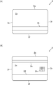
- the card used in the card issuing device described in Patent Document 1 has a magnetic stripe on which magnetic data is recorded. Specifically, as shown in FIG. 3, a magnetic stripe 2 b is formed on the back surface 2 a of the card 2, and two magnetic stripes 2 d and 2 e are formed on the front surface 2 c of the card 2.
- magnetic data is recorded on the magnetic stripes 2b and 2d and magnetic data recorded on the magnetic stripes 2b and 2d by the magnetic head of one of the two card readers. Data is read, and magnetic data is recorded on the magnetic stripe 2e and magnetic data recorded on the magnetic stripe 2e is read by the magnetic head of the other card reader.
- the card is stored in the wrong direction in the card storage unit due to an operator error or the like.
- the card may be stored in the card storage unit in a state where the front and rear direction of the card is opposite to the correct direction of the card stored in the card storage unit.
- the card issuing device described in Patent Document 1 performs card issuing processing on the assumption that the card is stored in the card storage unit in the correct orientation. For this reason, in this card issuing device, if the card issuance operation is performed in the wrong direction and the card issuance operation is performed, an abnormality such as a data recording error in the card reader may occur during the card issuance process. appear.
- an object of the present invention is to provide a method for controlling a card issuing device that can issue a card even if the card is stored in the wrong direction in the card storage unit.
- the subject of this invention is providing the card issuing apparatus which can issue a card
- a method for controlling a card issuing device includes a card accommodating unit that accommodates a card before issuance, and at least one of reading data recorded on the card and recording data on the card.
- a card issuer control method comprising a card reader for performing either one of them, a card orientation determination step for executing a determination process for determining the card orientation by taking the card into the card reader before issuing the card; And a card issuing step for executing a card issuing process based on the result of the determining process in the card orientation determining step.
- the card issuing device control method in the card orientation discrimination step, a discrimination process for taking the card into the card reader and discriminating the card orientation before issuing the card is executed, and the card after the card orientation discrimination step In the issuing step, the card issuing process is executed based on the result of the determining process in the card orientation determining step. Therefore, according to the present invention, it is possible to perform an appropriate card issuing process in accordance with the orientation of the card stored in the card storage unit. Therefore, in the present invention, it is possible to issue a card even if the card is stored in the wrong direction in the card storage unit.
- a card is a magnetic card on which a magnetic stripe on which magnetic data is recorded is formed, and a card reader performs recording of magnetic data on the card and reading of magnetic data recorded on the card.
- the card orientation determination step the magnetic data is recorded on and read from the card by the card reader, and the orientation of the card is determined based on the magnetic data read result.
- the card issuing device is provided with a card reversing mechanism for reversing the front and back of the card, and the card orientation determining step takes in the card sent from the card housing unit into the card reader and records and reads the magnetic data on the card.
- the card issuing device includes a first card reader and a second card reader as card readers, and the card is conveyed by the second card reader in the conveyance direction of the card conveyed by the first card reader.
- the card width direction is a direction perpendicular to the card conveyance direction and the thickness direction of the card to be conveyed
- the first card reader and the second card reader The issued card is taken in from one side in the card conveying direction, the magnetic head of the first card reader is arranged on one side in the card width direction, and the magnetic head of the second card reader is arranged in the card width direction.
- the card is taken into the first card reader in the first record reading step and the second record reading step, and the card orientation determining step is performed in the second record reading step.
- a third recording / reading step for recording and reading the magnetic data on the card by taking the card ejected from the first card reader into the second card reader when the magnetic data cannot be normally read in the taking step; It is preferable.
- This configuration makes it possible to determine the front and back orientation of the card. That is, with this configuration, it is possible to determine the front / back direction of the card and the front / rear direction of the card. Therefore, even if the card is stored in the card housing part with the card front and back being in the wrong direction, or even if the card is housed in the card housing part with the card front and back being wrong, It becomes possible to issue a card by performing a card issuance process.
- the card orientation determining step includes, for example, a second card reversing step in which the card is ejected from the first card reader before the third record reading step and the front and back of the card is reversed by the card reversing mechanism.
- the second card inversion step is executed, and the third recording / reading step is executed after the second card inversion step.
- the card orientation determining step includes a step of ejecting the card from the second card reader and reversing the front and back of the card by the card reversing mechanism when the magnetic data cannot be normally read in the third recording / reading step. It is preferable to include a three-card reversing step, and a fourth recording / reading step of taking the card into the second card reader after the third card reversing step and recording and reading the magnetic data on the card. If comprised in this way, if there is some abnormality in the card sent out from the card accommodating part, normal reading of magnetic data cannot be performed even in the fourth recording / reading step. Therefore, it is possible to determine whether or not there is any abnormality in the card sent out from the card accommodation unit based on the magnetic data reading result in the fourth recording reading step.
- the card issuing device includes a first card reader and a second card reader as card readers, and includes a card conveying direction conveyed by the first card reader and a card conveyed by the second card reader. Issuing to the first card reader and the second card reader when the direction of the card is the direction parallel to the transport direction and the direction perpendicular to the transport direction of the card and the thickness direction of the transported card is the width direction of the card.
- the first card reader magnetic head is arranged on one side of the card width direction
- the second card reader magnetic head is on the other side of the card width direction.
- the card sent out from the card storage unit is taken into the first card reader, and magnetic data is recorded on and read from the card.
- the card When the magnetic data cannot be normally read in the fifth record reading step and the fifth record reading step, the card is ejected from the first card reader and taken into the second card reader to record the magnetic data on the card. And a sixth record reading step for reading. In this case, it is possible to determine the front / rear direction of the card. Therefore, even if the card is stored in the card storage unit in the state where the front and back directions of the card are wrong, it is possible to issue the card by performing an appropriate card issuing process.
- the card issuing device includes a card reversing mechanism for reversing the front and back of the card, and the card orientation determining step is performed when the magnetic data cannot be normally read in the sixth recording / reading step.
- a fourth card reversing step for ejecting the card from the two-card reader and reversing the front and back of the card by the card reversing mechanism, and taking the card into the first card reader or the second card reader after the fourth card reversing step, and magnetic data for the card It is preferable to include a seventh record reading step for performing recording and reading.
- This configuration makes it possible to determine the orientation of the front and back of the card. That is, with this configuration, it is possible to determine the front / rear direction of the card and the front / back direction of the card. Therefore, even if the card is stored in the card storage unit with the front and back direction of the card being incorrect, or even if the card is stored in the card storage unit with the card front and back being incorrect, It becomes possible to issue a card by performing a card issuance process.
- the card issuing device includes a printer that prints an image on the card
- the card issuing step includes a printing step that prints an image on the card with the printer.
- the determination processing in the card orientation determination step is performed. Based on the result, the orientation of the image printed on the card is preferably determined. If comprised in this way, even if the card
- the card is an IC card in which an IC chip is incorporated and an external connection terminal of the IC chip is formed
- the card reader includes an IC contact block having a plurality of IC contact springs that contact the external connection terminal.
- the card activation process may be performed by a card reader, and the card orientation may be determined based on the result of the activation process.
- the card is a magnetic card on which a magnetic stripe on which magnetic data is recorded is formed, an IC card in which an IC chip is built and an external connection terminal of the IC chip is formed, and a card reader Comprises a magnetic head for recording magnetic data on a card and reading magnetic data recorded on the card, and an IC contact block having a plurality of IC contact springs in contact with external connection terminals, and a card orientation determining step Then, recording and reading of magnetic data with respect to the card and card activation processing may be performed by a card reader, and the orientation of the card may be determined based on the result of magnetic data reading and activation processing.
- the card reader includes a scanner that acquires an image of the card.
- the card orientation determination step the card image is acquired by the card reader, and the orientation of the card is determined based on the acquired image. Also good. In this case, it is possible to determine the orientation of the card only by acquiring the card image once.
- the card issuing device of the present invention includes at least one of a card storage unit that stores a card before issuance, reading of data recorded on the card, and recording of data on the card.
- a card reader that performs one of the tasks, and before the card is issued, the card is loaded into the card reader to perform a discrimination process to determine the card orientation, and the card issuance process is executed based on the result of the discrimination process. It is characterized by.
- the card issuing device executes a determination process for determining the card orientation by taking the card into the card reader before issuing the card, and executing the card issuing process based on the result of the determination process. . Therefore, according to the present invention, it is possible to perform an appropriate card issuing process in accordance with the orientation of the card stored in the card storage unit. Therefore, in the present invention, it is possible to issue a card even if the card is stored in the wrong direction in the card storage unit.
- FIG. 1 is a perspective view of a card issuing device according to an embodiment of the present invention. It is a figure for demonstrating the structure of the 1st floor part of the card issuing apparatus shown in FIG. It is a figure for demonstrating the card issued by the card issuing apparatus shown in FIG. It is a figure for demonstrating the card which can be issued with the card issuing apparatus shown in FIG. 2 is a list of cards that can be issued by the card issuing apparatus shown in FIG. It is a perspective view of the card inversion mechanism shown in FIG. It is a flowchart for demonstrating a part of operation
- FIG. 1 is a perspective view of a card issuing device 1 according to an embodiment of the present invention.
- FIG. 2 is a diagram for explaining the configuration of the first floor portion of the card issuing apparatus 1 shown in FIG.
- FIG. 3 is a diagram for explaining the card 2 issued by the card issuing apparatus 1 shown in FIG.
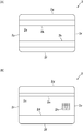
- FIG. 4 is a diagram for explaining a card 2 that can be issued by the card issuing apparatus 1 shown in FIG.
- FIG. 5 is a list of cards 2 that can be issued by the card issuing device 1 shown in FIG.
- FIG. 6 is a perspective view of the card transport mechanism 10 shown in FIG.
- the card issuing device 1 of this embodiment includes two card readers 3 and 4 that read data recorded on the card 2 and record data on the card 2, a printer 5 that prints an image on the card 2, a card 2, a label affixing machine (labeler) 6 for applying a label (seal), five card accommodating parts 7 for accommodating the cards 2 before issuance, and a card removing part 8 for taking out the issued cards 2
- the card collection unit 9 collects the cards 2 that are no longer needed, and the card transport mechanism 10 for transporting the cards 2 between these components. Note that the card issuing device 1 may not include the labeler 6.
- each of the three directions orthogonal to each other is defined as an X direction, a Y direction, and a Z direction.
- the Z direction is defined as the vertical direction.
- the X direction is the left-right direction
- the Y direction is the front-rear direction
- the X1 direction side of the left-right direction is the “right” side
- the opposite X2 direction side is the “left” side
- the front-rear direction The Y1 direction side is the “front” side
- the opposite Y2 direction side is the “rear” side
- the Z1 direction side of the vertical direction is the “upper” side
- the opposite side is the Z2 direction side Is the “lower” side.
- the card readers 3 and 4, the printer 5, and the labeler 6 are disposed on the front end side of the card issuing device 1.
- the card storage unit 7, the card removal unit 8, and the card collection unit 9 are disposed on the rear end side of the card issuing device 1.
- the card transport mechanism 10 is disposed at an intermediate position of the card issuing device 1 in the front-rear direction. In the front-rear direction, the card readers 3, 4, the printer 5, the labeler 6, the five card storage units 7, and the card take-out unit 8 and the card collection unit 9.
- the two card readers 3 and 4 are arranged so as to be adjacent in the left-right direction.
- the printer 5 and the labeler 6 are arranged so as to be adjacent in the left-right direction.
- the printer 5 and the labeler 6 are disposed above the card readers 3 and 4.
- Three of the five card accommodating portions 7 are arranged so as to be adjacent in the left-right direction.
- the card extraction unit 8 and the card recovery unit 9 are arranged so as to overlap in the vertical direction, and the remaining two card storage units 7, the card extraction unit 8 and the card recovery unit 9 are adjacent in the horizontal direction.
- the two card accommodating portions 7, the card extracting portion 8, and the card collecting portion 9 are disposed above the three card accommodating portions 7 that are adjacently disposed in the left-right direction.
- the card issuing device 1 has a so-called two-story structure, and the card readers 3 and 4 and the three card storage units 7 constitute the first floor portion of the card issuing device 1. (See FIG. 2).
- the printer 5, the labeler 6, the two card storage units 7, the card removal unit 8, and the card collection unit 9 constitute the second floor portion of the card issuing device 1.
- the card issuing device 1 may have a one-story structure.
- Card 2 is a substantially rectangular vinyl chloride card having a thickness of about 0.7 to 0.8 mm. As shown in FIG. 3, a magnetic stripe 2 b on which magnetic data is recorded is formed on the back surface 2 a of the card 2. On the front surface 2c of the card 2, a magnetic stripe 2d for recording magnetic data is formed.
- the magnetic stripes 2b and 2d are magnetic stripes defined by the JIS standard “JISX6302-2”. When viewed from the thickness direction of the card 2, the magnetic stripe 2b and the magnetic stripe 2d overlap.
- a magnetic stripe 2e on which magnetic data is recorded is formed on the front surface 2c of the card 2.
- the magnetic stripe 2e is formed in parallel with the magnetic stripe 2d.
- the width of the magnetic stripe 2e (width in the short direction of the card 2) is equal to the width of the magnetic stripe 2d (width in the short direction of the card 2).
- the distance between the short end direction 2f of the card 2 formed in a substantially rectangular shape and the magnetic stripe 2d is equal to the distance between the short end direction 2g of the card 2 and the magnetic stripe 2e.
- the card 2 includes an IC chip (not shown). On the front surface 2c of the card 2, external connection terminals 2h of IC chips are formed.
- the card 2 issued by the card issuing device 1 is a magnetic card on which magnetic stripes 2b, 2d, and 2e on which magnetic data is recorded are formed.
- the card 2 issued by the card issuing device 1 is also a contact type IC card in which an IC chip is built and an external connection terminal 2h is formed.
- the card issuing device 1 As shown in FIG. 4, it is possible to issue a card 2 having a magnetic stripe 2k on which magnetic data is recorded on the back surface 2a of the card 2.
- the magnetic stripe 2k is formed in parallel with the magnetic stripe 2b.
- the width of the magnetic stripe 2k (width in the short direction of the card 2) is equal to the width of the magnetic stripe 2b (width in the short direction of the card 2).
- the distance between the short end direction 2f of the card 2 and the magnetic stripe 2b is equal to the distance between the short end direction 2g of the card 2 and the magnetic stripe 2k.
- the card issuing device 1 can issue the card 2 on which the magnetic stripes 2b, 2d, 2e, and 2k are not formed. Further, the card issuing device 1 can issue the card 2 on which one, two, or three magnetic stripes arbitrarily selected from the magnetic stripes 2b, 2d, 2e, and 2k are formed. ing.
- the cards 2 that can be issued by the card issuing device 1 are summarized as shown in the list of FIG. That is, in the card issuing device 1, No. 1 in FIG. 1-No. Sixteen 16 types of cards 2 can be issued.
- JIS2-1 corresponds to the magnetic stripe 2d
- ISO-1 corresponds to the magnetic stripe 2b
- JIS2-2 corresponds to the magnetic stripe 2e
- ISO-2 corresponds to the magnetic stripe 2k
- a magnetic stripe marked with “ ⁇ ” is formed on the card 2
- a magnetic stripe marked with “x” is not formed on the card 2.
- the card 2 issued by the card issuing device 1 according to the present embodiment is the No. in the list of FIG. 8 card 2.
- the card readers 3 and 4 include a magnetic head 13 that records magnetic data on the card 2 and reads magnetic data recorded on the card 2.
- the card readers 3 and 4 of this embodiment are provided with two magnetic heads 13 arranged to face each other in the vertical direction. One of the two magnetic heads 13 is disposed so as to face the card transport path from the upper side, and the other magnetic head 13 is disposed so as to face the card transport path from the lower side.
- the two magnetic heads 13 are arranged at positions where the magnetic stripes 2b, 2d or the magnetic stripe 2e of the card 2 pass in the left-right direction.
- the card readers 3 and 4 include an IC contact block 14 having a plurality of IC contact springs (not shown) that come into contact with the external connection terminals 2 h of the card 2.
- the card reader 3 of this embodiment is a first card reader, and the card reader 4 is a second card reader.
- the card readers 3 and 4 are provided with a card 2 transport mechanism.
- the card 2 In the card readers 3 and 4, the card 2 is transported in the front-rear direction. That is, the conveyance direction of the card 2 conveyed by the card reader 3 and the conveyance direction of the card 2 conveyed by the card reader 4 are parallel.
- the issued card 2 is taken into the card readers 3 and 4 from the back side of the card readers 3 and 4 and discharged from the card readers 3 and 4 to the back side.
- the card readers 3 and 4 the card 2 is conveyed in a state where the longitudinal direction of the card 2 matches the front-rear direction and the short direction of the card 2 matches the left-right direction.
- the front-rear direction (Y direction) is the card 2 transport direction
- the vertical direction (Z direction) is the thickness direction of the card 2 being transported.
- the left-right direction (X direction) is the width direction (short width direction) of the card 2.
- the card reader 3 and the card reader 4 are configured similarly. That is, the card reader 3 and the card reader 4 are configured by arranging identical components in the same manner.
- the card reader 3 and the card reader 4 configured similarly are arranged so that the directions in the front-rear direction are opposite to each other. That is, the card reader 3 and the card reader 4 are arranged point-symmetrically with respect to the midpoint of the virtual line connecting the center of the card reader 3 and the center of the card reader 4 when viewed from the vertical direction. .
- the two magnetic heads 13 are arranged on the left rear end side of the card reader 3, and in the card reader 4, the two magnetic heads 13 are connected to the card reader 4. It is arranged on the right front end side. That is, the magnetic head 13 of the card reader 3 is disposed on one side in the left-right direction, which is the width direction of the card 2, and the magnetic head 13 of the card reader 4 is disposed on the other side in the left-right direction.
- the IC contact block 14 is disposed on the front end side of the card reader 3, and in the card reader 4, the IC contact block 14 is disposed on the rear end side of the card reader 4.
- the magnetic data recorded on the magnetic stripes 2b and 2d and the magnetic data recorded on the magnetic stripes 2b and 2d are read by the two magnetic heads 13 of the card reader 3, and the card reader 4 One of the two magnetic heads 13 reads the magnetic data recorded on the magnetic stripe 2e and records the magnetic data on the magnetic stripe 2e.
- data communication is performed between the card reader 3 and the card 2 using the IC contact block 14 of the card reader 3.
- the magnetic data recorded on the magnetic stripes 2b and 2d and the magnetic stripes can be read by the two magnetic heads 13 of the card reader 4.
- Magnetic data is recorded on 2b and 2d, and one of the two magnetic heads 13 of the card reader 3 reads the magnetic data recorded on the magnetic stripe 2e or onto the magnetic stripe 2e. Recording of magnetic data may be performed. Further, depending on the orientation of the card 2 accommodated in the card accommodating portion 7, data communication may be performed between the card reader 4 and the card 2 using the IC contact block 14 of the card reader 4.
- a card transport path is formed inside the printer 5. Further, the printer 5 includes a card 2 transport mechanism. In the printer 5, the card 2 is conveyed in the front-rear direction. In this embodiment, the issued card 2 is taken into the printer 5 from the back side of the printer 5 and discharged from the printer 5 to the back side. Further, in the printer 5, the card 2 is conveyed in a state where the longitudinal direction of the card 2 matches the front-rear direction and the short direction of the card 2 matches the left-right direction.
- the labeler 6 includes a card 2 transport mechanism.
- the card 2 is conveyed in the front-rear direction.
- the issued card 2 is taken into the labeler 6 from the back side of the labeler 6 and discharged from the labeler 6 to the back side.
- the card 2 is transported in a state where the longitudinal direction of the card 2 matches the front-rear direction and the short direction of the card 2 matches the left-right direction.
- the card taking-out part 8 and the card collecting part 9 are formed in a box shape whose upper surface is open.
- the card storage unit 7 includes a storage box in which a plurality of cards 2 before issuance are stacked and stored, and a delivery mechanism for the card 2 disposed below the storage box.
- the storage box is formed in a box shape whose upper end and rear end are open.
- the storage box accommodates the card 2 so that the longitudinal direction of the card 2 matches the front-rear direction, and the short side direction of the card 2 matches the left-right direction.
- the delivery mechanism includes, for example, a delivery claw that abuts against the rear end of the lowermost card 2 in the storage box and feeds the card 2 and a drive mechanism for the delivery claw, and is accommodated in the storage box. Send out cards 2 one by one toward the front.
- a delivery hole through which the card 2 delivered by the delivery mechanism passes is formed on the lower end side of the front side surface of the storage box.
- the card transport mechanism 10 linearly moves the carriage 17 in the left-right direction, two card holding units 15 and 16 that temporarily hold the card 2 inside, a carriage 17 on which the card holding units 15 and 16 are mounted.
- the card holding part 15 and the card holding part 16 are arranged so as to overlap in the vertical direction.
- the card holding portions 15 and 16 are rotatably held by the carriage 17. Specifically, the card holders 15 and 16 are held by the carriage 17 so that the card holders 15 and 16 can be rotated with the left-right direction as the axis direction of rotation.
- the card holding units 15 and 16 include a pull-in / out mechanism 22 that pulls in and out the card 2. Inside the card holders 15 and 16, a card transport path 27 through which the card 2 drawn or sent out by the pull-in / out mechanism 22 is formed linearly.
- the pull-out delivery mechanism 22 includes a driving roller 25, a pad roller 26 disposed opposite to the driving roller 25, a motor that rotates the driving roller 25, and a power transmission mechanism that transmits the power of the motor to the driving roller 25. ing.
- the pull-in / out mechanism 22 pulls the card 2 into the card transport path 27 and sends out the card 2 from the card transport path 27 so that the pull-in direction and the transport direction of the card 2 coincide with the longitudinal direction of the card 2. Further, the short direction of the card 2 drawn into the card transport path 27 coincides with the left-right direction.
- the guide shafts 19 and 20 are fixed to the support frame 21 so that the axial direction of the guide shafts 19 and 20 coincides with the left-right direction.
- the carriage 17 is supported by the guide shafts 19 and 20 so as to be slidable in the left-right direction.
- the carriage moving mechanism 18 includes a motor as a drive source and a power transmission mechanism that transmits the power of the motor to the carriage 17. When the motor of the carriage moving mechanism 18 rotates, the carriage 17 is guided by the guide shafts 19 and 20 and moves in the left-right direction.
- the rotation mechanism 24 includes a motor as a driving source and a power transmission mechanism that transmits the power of the motor to the card holding portions 15 and 16.
- the motor of the rotation mechanism 24 rotates, the card holding unit 15 and the card holding unit 16 rotate together in the same direction.
- the card holders 15 and 16 rotate with the left-right direction as the axis direction of rotation.
- the card holders 15 and 16 of the present embodiment are in a state where the card transport path 27 of the card holder 15 is parallel to the horizontal direction, and the card transport path 27 of the card holder 16 is parallel to the horizontal direction. Until the card transport path 27 of the card holders 15 and 16 is turned upside down, the left and right directions can be rotated 180 °.
- the front and back of the card 2 held in the card holding units 15 and 16 can be reversed.
- the card 2 held in the card holding portions 15 and 16 can be rotated with the short side direction of the card 2 being the rotation axis direction, so that the front and back of the card 2 can be reversed. It has become.
- the card transport mechanism 10 of this embodiment is a card reversing mechanism that reverses the front and back of the card 2.
- the card holders 15 and 16 are rotated to the middle position of the rotation range of the card holders 15 and 16 (that is, the card is held from the state where the card transport path 27 is parallel to the horizontal direction).
- the sections 15 and 16 are rotated by 90 °, the card 2 can be directly transferred between the card holding section 15 and the card holding section 16 in the vertical direction.
- the card transport path 27 when the card transport path 27 is parallel to the horizontal direction, the height of the card transport path of the card readers 3 and 4 and the height of the card transport path 27 of the card holding unit 16 in the vertical direction. And the height of the card conveyance path of the printer 5, the height of the card conveyance path of the labeler 6, and the height of the card conveyance path 27 of the card holding unit 15. Therefore, in a state where the card transport path 27 is parallel to the horizontal direction, the card 2 is transported between the card readers 3 and 4 and the card holding unit 16, and each of the printer 5 and the labeler 6 is held with the card. The card 2 can be transported to and from the unit 15.
- the height of the card transport path 27 of the card holding unit 15 and the upper side of the card 2 of the two card storage units 7 are arranged in the vertical direction.
- the height of the delivery hole coincides, and the height of the card transport path 27 of the card holding unit 16 and the height of the delivery hole of the card 2 of the three card accommodation units 7 arranged below coincide. . Therefore, in a state where the card transport path 27 is parallel to the horizontal direction, the card 2 sent out from the card storage unit 7 can be drawn into the card holding units 15 and 16.
- the card transport path 27 of the card holding unit 15 is disposed slightly above the bottom surface of the card removal unit 8.
- the front surface 2c of the card 2 faces upward, and one end surface 2p in the longitudinal direction of the card 2 is disposed on the front side.
- the other end surface 2r in the direction is arranged on the rear side (see FIG. 8A).
- the card reader 3 moves to the magnetic stripes 2b and 2d by the two magnetic heads 13. Normal recording of the magnetic data and normal reading of the magnetic data recorded on the magnetic stripes 2b and 2d become possible, and in the card reader 4, normal recording of the magnetic data on the magnetic stripe 2e by the magnetic head 13 is possible.
- the magnetic data recorded on the magnetic stripe 2e can be normally read.
- the card 2 in which the front surface 2c of the card 2 faces upward and the one end surface 2p in the longitudinal direction of the card 2 is arranged on the front side is taken into the card readers 3 and 4
- the magnetic data can be normally recorded on the magnetic stripes 2b and 2d by the magnetic heads 13 and the magnetic data recorded on the magnetic stripes 2b and 2d can be normally read. Normal recording of the magnetic data on the magnetic stripe 2e and normal reading of the magnetic data recorded on the magnetic stripe 2e are possible.
- the card reader 3 14 normal data communication between the card reader 3 and the card 2 becomes possible.
- a card 2 in which the front surface 2c of the card 2 faces upward and the other end surface 2r in the longitudinal direction of the card 2 is disposed on the front side is taken into the card readers 3 and 4.
- the card reader 4 can perform normal recording of magnetic data on the magnetic stripes 2b and 2d by the two magnetic heads 13 and normal reading of the magnetic data recorded on the magnetic stripes 2b and 2d.
- the magnetic head 13 can normally record the magnetic data on the magnetic stripe 2e and can normally read the magnetic data recorded on the magnetic stripe 2e.
- FIG. 7 is a flowchart for explaining a part of the operation of the card issuing apparatus 1 shown in FIG.
- FIG. 8 is a view for explaining the orientation of the card 2 accommodated in the card accommodating portion 7 shown in FIG. In FIG. 8, the external connection terminal 2h is not shown.
- the card issuing device 1 When a card 2 issuance command is input to the card issuing device 1 from a higher-level device such as a personal computer to which the card issuing device 1 is connected, the card issuing device 1 sends a card to the card readers 3 and 4 before issuing the card 2. 2 is executed to execute the determination process for determining the orientation of the card 2, and the card 2 issuance process is executed based on the result of the determination process. Specifically, as shown in FIG. 7, when an issuance command for a card 2 is input to the card issuing device 1, the card issuing device 1 first stores the card 2 sent out from the card storage unit 7 as the first card. The data is taken into the card reader 3 which is a reader, and magnetic data is recorded on and read from the card 2 (step S1).
- step S1 the card transport mechanism 10 transports the card 2 sent out from the card storage unit 7 to the card reader 3, and the card reader 3 takes in the transported card 2.
- the orientation of the card 2 taken into the card reader 3 matches the orientation of the card 2 when accommodated in the card accommodation portion 7.
- step S ⁇ b> 1 the card reader 3 records and reads magnetic data with respect to the card 2 by the two magnetic heads 13 of the card reader 3 while conveying the card 2. Specifically, the card reader 3 records the magnetic data on the card 2 with the two magnetic heads 13 and then reads the magnetic data. Thereafter, the card issuing device 1 determines whether or not the magnetic data can be normally read by the two magnetic heads 13 in step S1 (step S2).
- step S1 when the card 2 accommodated in the card accommodating portion 7 in the correct orientation is taken into the card reader 3 in the same orientation, the magnetic data on the card 2 by the two magnetic heads 13 is read by the card reader 3. Normal recording and normal reading of the magnetic data recorded on the card 2 become possible. Therefore, when the card 2 sent out from the card accommodating part 7 is accommodated in the card accommodating part 7 in the correct orientation (when the card 2 is accommodated in the card accommodating part 7 in the direction shown in FIG. 8A). In step S1, appropriate magnetic data can be recorded in the magnetic stripes 2b and 2d, and as a result, the magnetic data can be read normally.
- the magnetic stripe 2b formed by the two magnetic heads 13 in the card reader 3 is used.
- normal recording of the magnetic data on 2d and normal reading of the magnetic data recorded on the magnetic stripes 2b and 2d become possible.
- the magnetic data on the magnetic stripe 2e by the magnetic head 13 is normal. Recording and normal reading of magnetic data recorded on the magnetic stripe 2e are possible, and the card reader 3 can communicate normal data between the card reader 3 and the card 2 using the IC contact block 14. become.
- step S2 if it is determined in step S2 that the magnetic data can be normally read by the two magnetic heads 13 (that is, if “Yes” in step S2), the card issuing device 1 After erasing the magnetic data recorded on the card 2 in S1, the issuing process of the card 2 is started.
- the card 2 sent out from the card storage unit 7 has the front / back and front / rear orientations of the card 2 with respect to the correct orientation of the card 2 stored in the card storage unit 7.
- the card is housed in the card housing portion 7 in the opposite state (the front and back of the card 2 are reversed and the other end surface 2r of the card 2 is disposed on the front side), and the card housing portion 7
- the card 2 sent out from the card 2 is in a state where the front and back sides and the left and right directions of the card 2 are opposite to the correct orientation of the card 2 stored in the card storage unit 7.
- the card 2 sent out from the card storage unit 7 has the front and rear and left and right directions of the card 2 with respect to the correct orientation of the card 2 stored in the card storage unit 7.
- the card is stored in the card storage unit 7 in the opposite state, one of the two magnetic heads 13 of the card reader 3 cannot properly record magnetic data in step S1. As a result, the magnetic data cannot be read normally.
- step S2 when it is determined in step S2 that the magnetic data cannot be normally read by at least one magnetic head 13 (that is, in the case of “No” in step S2), the card issuing device 1
- the card 2 is discharged from the card reader 3, and the card transport mechanism 10 reverses the front and back of the card 2 (step S3).
- the card issuing device 1 rotates the card 2 with the short direction of the card 2 being the axial direction of rotation, and reverses the front and back of the card 2.
- the card issuing device 1 takes the card 2 with the front and back reversed into the card reader 3 again, and records and reads the magnetic data on the card 2 (step S4).
- the card reader 3 records the magnetic data on the card 2 by the two magnetic heads 13 of the card reader 3 while transporting the card 2, and then reads the magnetic data.
- the card issuing device 1 determines whether or not the magnetic data can be normally read by the two magnetic heads 13 in step S4 (step S5).
- step S4 the card 2 is in the direction shown in FIG. 8A. Captured by the reader 3.
- the card reader 3 performs normal recording of magnetic data on the magnetic stripes 2b and 2d by the two magnetic heads 13.
- the magnetic data recorded on the magnetic stripes 2b and 2d can be normally read.
- the magnetic data is normally recorded on the magnetic stripe 2e by the magnetic head 13 and the magnetic data recorded on the magnetic stripe 2e. Data can be read normally, and in the card reader 3, normal data communication between the card reader 3 and the card 2 using the IC contact block 14 becomes possible.
- step S5 when it is determined in step S5 that the magnetic data can be normally read by the two magnetic heads 13 (that is, in the case of “Yes” in step S5), the card issuing device 1 After erasing the magnetic data recorded on the card 2 in S5, the card 2 issuing process is started.
- step S5 determines whether the magnetic data cannot be normally read by at least one magnetic head 13 (that is, if “No” in step S5)
- the card issuing device 1 The card 2 is discharged from the card reader 3, and the card transport mechanism 10 reverses the front and back of the card 2 (step S6).
- step S ⁇ b> 6 the card issuing device 1 rotates the card 2 with the short side direction of the card 2 being the axial direction of rotation, and reverses the front and back of the card 2.
- the card issuing device 1 takes the card 2 with the front and back reversed into the card reader 4 as the second card reader, and records and reads the magnetic data on the card 2 (step S7).
- the card transport mechanism 10 transports to the card reader 4, and the card reader 4 takes in the transported card 2.
- the card reader 4 records the magnetic data on the card 2 by the two magnetic heads 13 of the card reader 4 while transporting the card 2, and then reads the magnetic data.
- the card issuing device 1 determines whether or not the magnetic data can be normally read by the two magnetic heads 13 in step S7 (step S8).
- step S7 the card 2 is in the direction shown in FIG. 8C. Captured by the reader 4.
- step S7 the magnetic data is appropriately recorded on the magnetic stripes 2b and 2d by the two magnetic heads 13. As a result, the magnetic data can be read normally.
- the magnetic data on the magnetic stripes 2b and 2d by the two magnetic heads 13 in the card reader 4 is normal. Recording and normal reading of the magnetic data recorded on the magnetic stripes 2b and 2d becomes possible, and the card reader 3 allows the magnetic head 13 to normally record the magnetic data on the magnetic stripe 2e and to record on the magnetic stripe 2e. Thus, normal reading of the magnetic data can be performed, and in the card reader 4, normal data communication between the card reader 4 and the card 2 using the IC contact block 14 becomes possible.
- step S8 when it is determined in step S8 that the magnetic data can be normally read by the two magnetic heads 13 (that is, in the case of “Yes” in step S8), the card issuing device 1 It is stored that the front / rear and left / right orientations of the card 2 on which the discrimination processing is being performed are opposite to the correct orientation of the card 2 accommodated in the card accommodating portion 7 (step S9), and step S7. After erasing the magnetic data recorded on the card 2, the card 2 issuance process is started.
- step S8 determines whether the magnetic data cannot be normally read by at least one magnetic head 13 (that is, if “No” in step S8)
- the card issuing device 1 The card 2 is discharged from the card reader 4, and the card transport mechanism 10 reverses the front and back of the card 2 (step S10). Specifically, in step S10, the card issuing device 1 rotates the card 2 with the short side direction of the card 2 being the axial direction of rotation, and reverses the front and back of the card 2.
- the card issuing device 1 takes the card 2 with the front and back reversed into the card reader 4 and records and reads the magnetic data on the card 2 (step S11).
- the card reader 4 records the magnetic data on the card 2 by the two magnetic heads 13 of the card reader 4 while carrying the card 2, and then reads the magnetic data.
- the card issuing device 1 determines whether or not the magnetic data can be normally read by the two magnetic heads 13 in step S11 (step S12).
- step S11 When the card 2 sent out from the card accommodating portion 7 is accommodated in the card accommodating portion 7 in the direction shown in FIG. 8D, in step S11, the card 2 is in the orientation shown in FIG. 8C. Captured by the reader 3. Therefore, when it is determined in step S12 that the magnetic data can be normally read by the two magnetic heads 13 (that is, in the case of “Yes” in step S12), the process proceeds to step S9 and the card The issuing device 1 stores the fact that the front and rear and left and right orientations of the card 2 that is currently being discriminated are opposite to the correct orientation of the card 2 that is accommodated in the card accommodating portion 7, and After erasing the magnetic data recorded on the card 2 in step S11, the card 2 issuing process is started.
- step S12 if it is determined in step S12 that the magnetic data cannot be normally read by at least one magnetic head 13 (that is, if “No” in step S12), the card issuing device 1 It is determined that there is some abnormality in the card 2 sent out from the card accommodation unit 7, and card abnormality processing is executed. For example, the card issuing device 1 abnormally stops. Alternatively, the card issuing device 1 collects the card 2 in the card collection unit 9, sends out a new card 2 from the card storage unit 7, and returns to step S1.
- the card 2 is first taken into the card reader 3 in the same direction.
- the card reader 3 performs recording of the magnetic data on the magnetic stripes 2b and 2d and reading of the magnetic data for confirming the recorded magnetic data. Further, the card reader 3 performs data communication with the card 2 using the IC contact block 14. Thereafter, the card 2 is ejected from the card reader 3 and is transported to the card transport mechanism 10 and then taken into the card reader 4 as it is.
- the card reader 4 performs recording of magnetic data on the magnetic stripe 2e and reading of magnetic data for confirming the recorded magnetic data.
- the card 2 Is taken in the card reader 4 in the same direction.
- the card reader 4 performs recording of the magnetic data on the magnetic stripes 2b and 2d and reading of the magnetic data for confirming the recorded magnetic data. Further, the card reader 4 performs data communication with the card 2 using the IC contact block 14. Thereafter, the card 2 is ejected from the card reader 4 and is transported to the card transport mechanism 10 and then taken into the card reader 3 as it is.
- the card reader 3 performs recording of magnetic data on the magnetic stripe 2e and reading of magnetic data for confirming the recorded magnetic data.
- the magnetic data may not be recorded on the magnetic stripes 2b and 2d, or the magnetic data may not be recorded on the magnetic stripe 2e.
- data communication using the IC contact block 14 may not be performed between the card reader 3 or the card reader 4 and the card 2.
- the card 2 that has been processed by the card readers 3 and 4 is transferred to the card transfer mechanism 10 and then taken into the printer 5.
- the printer 5 prints an image on the card 2.
- the printer 5 determines the orientation of the image printed on the card 2 in accordance with the orientation of the card 2 captured by the printer 5. Specifically, when the card 2 in which the front surface 2c of the card 2 faces upward and the one end surface 2p in the longitudinal direction of the card 2 is arranged on the front side is taken into the printer 5 (“Yes” in step S2). If the result is “Yes” and “Yes” in step S5), the printer 5 prints an image in the normal orientation on the card 2.
- step S8 when the card 2 having the front surface 2c of the card 2 facing upward and the other end surface 2r in the longitudinal direction of the card 2 disposed on the front side is taken into the printer 5 (“Yes” in step S8). In this case, and when “Yes” is determined in step S12), the printer 5 prints an image rotated 180 ° from the normal direction on the card 2.
- the card 2 is ejected from the printer 5 and conveyed to the card conveying mechanism 10 and then taken into the labeler 6.
- the labeler 6 attaches a label to the card 2.
- the card 2 is ejected from the labeler 6 and conveyed to the card extraction unit 8 by the card conveying mechanism 10. Further, when the card 2 is ejected to the card removal unit 8, the card 2 issuance process is completed. In the card 2 issuing process, an image may not be printed on the card 2 and a label may not be attached to the card 2.
- Step S1 in this embodiment is a first recording step in which the card 2 sent out from the card storage unit 7 is taken into the card reader 3 and recording and reading of magnetic data with respect to the card 2 are performed.
- Step S3 is step S1.
- This is a card reversal step in which when the magnetic data cannot be read normally, the card 2 is ejected from the card reader 3 and the front and back of the card 2 are reversed.
- Step S4 is a card reversal step after the step S3. And a second recording / reading step for recording and reading magnetic data on the card 2.
- step S7 when the magnetic data cannot be normally read in step S4, the card 2 ejected from the card reader 3 is taken into the card reader 4 and the magnetic data is recorded and read on the card 2.
- step S6 is a second card reversing step for discharging the card 2 from the card reader 3 and reversing the front and back of the card 2 before step S7.
- step S10 is a third card reversal step in which the card 2 is ejected from the card reader 4 and the front and back of the card 2 are reversed when the magnetic data cannot be normally read in step S7.
- This is a fourth recording / reading step in which the card 2 is taken into the card reader 4 after step S10 and magnetic data is recorded on and read from the card 2.
- steps S1 to S12 of this embodiment are card orientation determination steps for executing a discrimination process for taking the card 2 into the card readers 3 and 4 and discriminating the orientation of the card 2 before issuing the card 2. .
- the card orientation determination step recording and reading of magnetic data with respect to the card 2 are performed by the card readers 3 and 4, and the orientation of the card 2 is determined based on the reading result of the magnetic data. Specifically, in the card orientation determination step, it is determined which orientation shown in FIGS. 8A to 8D is the orientation of the card 2 accommodated in the card accommodating portion 7.
- the step of executing the card 2 issuing process is a card issuing step of executing the card 2 issuing process based on the result of the determination process in the card orientation determining step.
- the control method of the card issuing device 1 includes the card orientation determining step and the card issuing step.
- the step in which the printer 5 prints an image on the card 2 is a printing step.
- the printing step the card 2 is loaded on the card 2 based on the result of the discrimination processing in the card orientation discrimination step. The orientation of the image to be printed is determined.
- step S1 the card 2 sent out from the card storage unit 7 is taken into the card reader 3 to record and read the magnetic data on the card 2, and the magnetic data cannot be read normally in step S1.
- step S4 the card 2 with the front and back reversed is taken into the card reader 3 to record and read magnetic data from the card 2. Therefore, in this embodiment, it is possible to determine the front / back orientation of the card 2. Therefore, in this embodiment, even if the card 2 is stored in the card storage unit 7 with the card 2 facing in the wrong direction, the card 2 is issued by appropriately recording magnetic data or the like on the card 2. Is possible.
- the two magnetic heads 13 of the card reader 3 are arranged on the left rear end side of the card reader 3, and the two magnetic heads 13 of the card reader 4 are on the right front end side of the card reader 4. If the magnetic data cannot be normally read in step S4, the card 2 is taken into the card reader 4 and the magnetic data is recorded and read in the card 2 in step S7. Therefore, in this embodiment, it is possible to determine the front-rear direction of the card 2. Therefore, in this embodiment, even when the card 2 is stored in the card storage unit 7 in a state where the front and rear directions of the card 2 are wrong, the card 2 is issued by appropriately recording magnetic data or the like on the card 2. Is possible.
- the card 2 is stored in the card storage unit 7 in a state where the front and back of the card 2 and the front and back directions are opposite to the correct direction of the card 2 stored in the card storage unit 7.
- the card 2 is stored in the card storage portion 7 in a state where the front and rear and left and right directions of the card 2 are opposite to the correct orientation of the card 2 stored in the card storage portion 7,
- the card 2 It is possible to issue the card 2 by appropriately recording magnetic data or the like.
- the card 2 with the front and back reversed is taken into the card reader 4 in step S11, and the magnetic data is recorded and read on the card 2. If there is any abnormality in the card 2 sent out from the card storage unit 7, the magnetic data cannot be normally read even in step S11. For this reason, in this embodiment, it is possible to determine whether or not there is any abnormality in the card 2 sent out from the card storage unit 7 based on the magnetic data read result in step S11. For example, it is possible to determine whether or not the card 2 sent out from the card storage unit 7 is a different type of card 2 from the card 2 to be issued. Alternatively, it is possible to determine whether or not the card 2 sent out from the card storage unit 7 is damaged.
- the printer 5 determines the orientation of the image printed on the card 2 according to the orientation of the card 2 taken into the printer 5 and prints the image on the card 2. Therefore, in this embodiment, even if the card 2 is stored in the card storage unit 7 in a state where the front and rear directions of the card 2 are wrong, it is possible to print an appropriate image on the card 2 using the common printer 5. become.
- the card 2 issued by the card issuing device 1 is the No. in the list of FIG. 8, other cards 2 in the list of FIG. 5 may be issued by the card issuing device 1.
- Cards 2 (No. 2 to No. 4, No. 7, No. 10, No. 12, No. 14, No. 15 cards 2) grouped into “Group 1” in the list of FIG.
- the card issuing device 1 executes the same card orientation determination steps S1 to S12 as those described above before issuing the card 2, for example, to change the orientation of the card 2. Determine.
- the card issuing device 1 performs recording and reading of magnetic data on the card 2 with one magnetic head 13 in step S 1 and the like.
- the card issuing device 1 issues any of the cards 2 (No. 5, No. 9, No. 13 cards 2) grouped into “Group 2” in the list of FIG.
- the card issuing device 1 executes card orientation determining steps S1 to S12 that are substantially the same as those described above to determine the orientation of the card 2.
- the card issuing device 1 takes in the card reader 4 in steps S1 and S4 to record and read magnetic data on the card 2, and takes in the card reader 3 in steps S7 and S11. Recording and reading of magnetic data with respect to the card 2 are performed.
- the card reader 3 is a second card reader
- the card reader 4 is a first card reader.
- the card issuing device 1 records and reads the magnetic data with respect to the card 2 by one magnetic head 13 in step S 1 and the like.
- the card issuing device 1 issues any of the cards 2 (No. 6, No. 11, No. 16 cards 2) grouped into “Group 3” in the list of FIG. Although it is possible to determine the front / back orientation of the card 2, it is not possible to determine the front / rear direction of the card 2. Therefore, in this case, for example, before issuing the card 2, the card issuing device 1 executes a card orientation determining step including steps S1 to S5 to determine the orientation of the card 2. In this case, if “No” in the step S5, the card issuing device 1 executes a card abnormality process. In this case, depending on the type of the card 2, the card issuing device 1 records and reads the magnetic data with respect to the card 2 by one magnetic head 13 in step S 1 and the like.
- the card issuing device 1 issues cards 2 (No. 1 cards 2) that are grouped into “group 0” in the list of FIG. 5, the front and back direction of the card 2 and the card 2 In this case, the card issuing device 1 starts the card 2 issuing process without executing the card orientation determining step.
- the card issuing device 1 has different Nos.
- a plurality of types of cards 2 may be issued.
- the same type of card 2 is accommodated in each card accommodating portion 7.
- the card 2 issuance command is issued from the host device in accordance with the No. of the issued card 2.
- the card issuing device 1 includes the No. of the card 2 included in the card 2 issue command.
- the card 2 is sent out from the card accommodating portion 7 corresponding to the card 2 and the card 2 No.
- a card orientation determination step corresponding to the card is executed.
- step S2 when the magnetic data cannot be normally read in step S1 (that is, “No” in step S2), the card issuing device 1 ejects the card 2 from the card reader 3 and the card.
- a sixth recording / reading step may be executed in which the reader 4 captures and reads / writes magnetic data from / to the card 2.
- the front and rear direction of the card 2 can be determined. Therefore, even if the card 2 is stored in the card storage unit 7 in a state where the front and rear directions of the card 2 are wrong, it is possible to appropriately record magnetic data or the like on the card 2 and issue the card 2. .
- the card issuing device 1 ejects the card 2 from the card reader 4 and the card transport mechanism 10 reverses the front and back of the card 2.
- a four-card reversing step and a seventh recording / reading step in which the card 2 is taken into the card reader 3 or the card reader 4 after the fourth card reversing step to record and read magnetic data on the card 2 may be executed.
- the front / back orientation of the card 2 can also be determined.
- the card 2 is accommodated in the card accommodating portion 7 in a state where the front and back of the card 2 and the front and back directions are opposite to the correct orientation of the card 2 accommodated in the card accommodating portion 7.
- the card 2 is stored in the card storage unit 7 in a state where the front and rear and left and right directions of the card 2 are opposite to the correct direction of the card 2 stored in the card storage unit 7.
- the card 2 can be issued by appropriately recording magnetic data or the like on the card 2.
- the card orientation determining step recording and reading of magnetic data with respect to the card 2 are performed by the card readers 3 and 4, and the orientation of the card 2 is determined based on the reading result of the magnetic data.
- the card 2 activation process may be performed by the card reader 1 and the card 2 orientation may be determined based on the result of the activation process.
- the card issuing device 1 performs the activation process of the card 2 by bringing the IC contact into contact with the card 2 taken into the card reader 3, and in steps S7 and S11, the card reader 4
- the IC contact may be brought into contact with the card 2 taken in to perform the activation process of the card 2, and it may be determined whether or not the card 2 is activated in steps S2, S5, S8, and S12.
- the magnetic stripes 2b, 2d, and 2e may not be formed on the card 2. That is, the card 2 may not be a magnetic card.
- the card issuing device 1 performs recording and reading of magnetic data on the card 2 and activation processing of the card 2 by the card readers 3 and 4 and reading results and activation processing of the magnetic data.
- the orientation of the card 2 may be discriminated based on the result. That is, the card issuing device 1 may determine the orientation of the card 2 based on the combination of the magnetic data reading result and the activation processing result in the card orientation determining step.
- the card reader 3 includes a scanner 30 (see a two-dot chain line in FIG. 2) that acquires an image of the card 2, the card issuing device 1
- the image may be acquired by the card reader 3 and the orientation of the card 2 may be determined based on the acquired image.
- the orientation of the card 2 can be determined only by acquiring the image of the card 2 once.
- the card 2 may not be a magnetic card and may not be an IC card.
- the card issuing device 1 ends the determination of the orientation of the card 2 and proceeds to the card 2 issuing process when the magnetic data is normally read. However, if the magnetic data cannot be read normally, the card issuing device 1 may end the determination of the orientation of the card 2 according to the magnetic data reading status and proceed to the card 2 issuing process.
- step S 1 one of the two magnetic heads 13 of the card reader 3 cannot normally read magnetic data, but the other magnetic head 13 does not read magnetic data normally. If it is possible, it is assumed that the card 2 is accommodated in the card accommodating portion 7 in the state shown in FIG. 8C. In this case, the process may proceed to step S9. Further, for example, if “No” in step S8, it is assumed that the card 2 is accommodated in the card accommodating portion 7 in the state shown in FIG. 8D. In this case, step S10 is performed. After execution, the process may proceed to step S9. If “No” in step S8, the card issuing device 1 stores the fact that the front and back directions of the card 2 are correct but the front and back directions of the card 2 are opposite, and starts the card 2 issuing process. May be.
- the card issuing device 1 may not include the card reader 3 or the card reader 4.
- the card abnormality process may be executed when “No” in step S5. Even in this case, it is possible to determine the front and back direction of the card 2.
- the card conveyance mechanism 10 does not need to be provided with the function to reverse the front and back of the card 2. Even in this case, the front-rear direction of the card 2 can be determined.
- step S5 the process may proceed to step S7 without inverting the front and back of the card 2.
- the card transport mechanism 10 reverses the front and back of the card 2, but the card issuing device 1 includes a card reversing mechanism that reverses the front and back of the card 2 separately from the card transport mechanism 10. May be.
- the card reader 3 and the card reader 4 are comprised similarly, the structure of the card reader 3 and the structure of the card reader 4 may differ.
- the number of the card accommodating units 7 included in the card issuing device 1 may be four or less, or may be six or more. Moreover, in the form mentioned above, the card issuing apparatus 1 may be provided with three or more card readers.
- the card 2 may not include an IC chip.
- the card 2 may be a PET (polyethylene terephthalate) card having a thickness of about 0.18 to 0.36 mm or a predetermined thickness. It may be a paper card.
Landscapes
- Engineering & Computer Science (AREA)
- Physics & Mathematics (AREA)
- General Physics & Mathematics (AREA)
- Theoretical Computer Science (AREA)
- Artificial Intelligence (AREA)
- Computer Vision & Pattern Recognition (AREA)
- Conveying Record Carriers (AREA)
- Control Of Vending Devices And Auxiliary Devices For Vending Devices (AREA)
Abstract
La présente invention a pour but de fournir un procédé de commande d'un dispositif d'émission de carte, grâce auquel il serait possible d'émettre une carte même si la carte est logée en une orientation erronée dans une unité de logement de carte. L'invention concerne un procédé de commande d'un dispositif d'émission de carte qui comprend une unité de logement de carte dans laquelle des cartes sont logées avant d'être émises et des lecteurs de carte qui exécutent chacun la lecture de données ayant été enregistrées sur les cartes et/ou enregistrant des données sur les cartes, le procédé comprenant des étapes S1-S12 d'évaluation d'orientation de carte consistant à exécuter un processus d'évaluation pour prendre une carte dans les lecteurs de carte avant l'émission de la carte et à évaluer l'orientation de la carte; une étape d'émission de carte consistant à exécuter un processus d'émission de carte sur la base du résultat du processus d'évaluation dans les étapes S1-S12 d'évaluation d'orientation de carte.
Priority Applications (2)
| Application Number | Priority Date | Filing Date | Title |
|---|---|---|---|
| US16/488,631 US11138481B2 (en) | 2017-02-27 | 2018-02-07 | Control method of card issue device and card issue device |
| CN201880013909.7A CN110337657B (zh) | 2017-02-27 | 2018-02-07 | 卡片发行装置的控制方法及卡片发行装置 |
Applications Claiming Priority (2)
| Application Number | Priority Date | Filing Date | Title |
|---|---|---|---|
| JP2017034752A JP6906328B2 (ja) | 2017-02-27 | 2017-02-27 | カード発行装置の制御方法およびカード発行装置 |
| JP2017-034752 | 2017-02-27 |
Publications (1)
| Publication Number | Publication Date |
|---|---|
| WO2018155180A1 true WO2018155180A1 (fr) | 2018-08-30 |
Family
ID=63253231
Family Applications (1)
| Application Number | Title | Priority Date | Filing Date |
|---|---|---|---|
| PCT/JP2018/004136 Ceased WO2018155180A1 (fr) | 2017-02-27 | 2018-02-07 | Procédé de commande de dispositif d'émission de carte et dispositif d'émission de carte |
Country Status (4)
| Country | Link |
|---|---|
| US (1) | US11138481B2 (fr) |
| JP (1) | JP6906328B2 (fr) |
| CN (1) | CN110337657B (fr) |
| WO (1) | WO2018155180A1 (fr) |
Families Citing this family (1)
| Publication number | Priority date | Publication date | Assignee | Title |
|---|---|---|---|---|
| CN109800825B (zh) * | 2018-12-29 | 2022-04-29 | 航天信息股份有限公司 | 制证控制方法、装置、存储介质以及电子设备 |
Citations (5)
| Publication number | Priority date | Publication date | Assignee | Title |
|---|---|---|---|---|
| JPH0531981A (ja) * | 1991-07-26 | 1993-02-09 | Victor Co Of Japan Ltd | カード発行装置 |
| JP2000099806A (ja) * | 1998-09-24 | 2000-04-07 | Sankyo Seiki Mfg Co Ltd | カード発行装置 |
| JP2000222608A (ja) * | 1999-01-29 | 2000-08-11 | Amano Corp | カード処理装置 |
| JP2006031432A (ja) * | 2004-07-16 | 2006-02-02 | Nidec Sankyo Corp | カードリーダ |
| JP2013239003A (ja) * | 2012-05-15 | 2013-11-28 | Toppan Printing Co Ltd | 白カード検査装置 |
Family Cites Families (3)
| Publication number | Priority date | Publication date | Assignee | Title |
|---|---|---|---|---|
| JP5648024B2 (ja) * | 2012-07-10 | 2015-01-07 | 日本電産サンキョー株式会社 | カードリーダ |
| JP2015149033A (ja) * | 2014-02-10 | 2015-08-20 | 日本電産サンキョー株式会社 | カード発行装置 |
| JP6234855B2 (ja) * | 2014-03-18 | 2017-11-22 | 日本電産サンキョー株式会社 | カード搬送機構およびカード発行装置 |
-
2017
- 2017-02-27 JP JP2017034752A patent/JP6906328B2/ja active Active
-
2018
- 2018-02-07 WO PCT/JP2018/004136 patent/WO2018155180A1/fr not_active Ceased
- 2018-02-07 US US16/488,631 patent/US11138481B2/en not_active Expired - Fee Related
- 2018-02-07 CN CN201880013909.7A patent/CN110337657B/zh active Active
Patent Citations (5)
| Publication number | Priority date | Publication date | Assignee | Title |
|---|---|---|---|---|
| JPH0531981A (ja) * | 1991-07-26 | 1993-02-09 | Victor Co Of Japan Ltd | カード発行装置 |
| JP2000099806A (ja) * | 1998-09-24 | 2000-04-07 | Sankyo Seiki Mfg Co Ltd | カード発行装置 |
| JP2000222608A (ja) * | 1999-01-29 | 2000-08-11 | Amano Corp | カード処理装置 |
| JP2006031432A (ja) * | 2004-07-16 | 2006-02-02 | Nidec Sankyo Corp | カードリーダ |
| JP2013239003A (ja) * | 2012-05-15 | 2013-11-28 | Toppan Printing Co Ltd | 白カード検査装置 |
Also Published As
| Publication number | Publication date |
|---|---|
| JP6906328B2 (ja) | 2021-07-21 |
| US20210133519A1 (en) | 2021-05-06 |
| CN110337657B (zh) | 2023-06-16 |
| JP2018142073A (ja) | 2018-09-13 |
| US11138481B2 (en) | 2021-10-05 |
| CN110337657A (zh) | 2019-10-15 |
Similar Documents
| Publication | Publication Date | Title |
|---|---|---|
| CN107555227B (zh) | 介质处理装置 | |
| US5317138A (en) | Information recording and or reproducing apparatus for use in hybrid type information recording medium | |
| US11724903B2 (en) | Card processing device | |
| CN102089771A (zh) | 卡处理单元及发卡装置 | |
| WO2018155180A1 (fr) | Procédé de commande de dispositif d'émission de carte et dispositif d'émission de carte | |
| CN100562888C (zh) | 记录媒体处理装置 | |
| JP2009266107A (ja) | カードリーダ | |
| US10682867B2 (en) | Card processing device | |
| US11186096B2 (en) | Card-issuing device | |
| JP2019079196A (ja) | カード反転ユニットおよびカード処理装置 | |
| JPH07104893B2 (ja) | 通帳磁気データ読取装置 | |
| JP2008105832A (ja) | 媒体処理装置 | |
| JP4843773B2 (ja) | 情報処理システム,媒体処理装置,及びデバイス認識方法 | |
| JP2006031432A (ja) | カードリーダ | |
| US20230348213A1 (en) | Card conveyance unit | |
| JP2919052B2 (ja) | 券発行装置 | |
| JP5866926B2 (ja) | 記録装置、記録装置の制御方法、及び、プログラム | |
| JP2021026326A5 (fr) | ||
| JPH0668875B2 (ja) | 電源投入時のカ−ド搬送処理方法 | |
| JPH08129598A (ja) | 通帳類取扱装置 | |
| JPH0795386B2 (ja) | 媒体発行装置 | |
| JP2002074470A (ja) | 遊技装置用記憶媒体読み書き装置 | |
| JPH04160588A (ja) | 媒体取り扱い装置 | |
| JPH0370829B2 (fr) | ||
| JPH03210694A (ja) | 通帳伝票処理装置の処理方法 |
Legal Events
| Date | Code | Title | Description |
|---|---|---|---|
| 121 | Ep: the epo has been informed by wipo that ep was designated in this application |
Ref document number: 18756765 Country of ref document: EP Kind code of ref document: A1 |
|
| NENP | Non-entry into the national phase |
Ref country code: DE |
|
| 122 | Ep: pct application non-entry in european phase |
Ref document number: 18756765 Country of ref document: EP Kind code of ref document: A1 |