WO2018159371A1 - 遠心圧縮機 - Google Patents
遠心圧縮機 Download PDFInfo
- Publication number
- WO2018159371A1 WO2018159371A1 PCT/JP2018/005871 JP2018005871W WO2018159371A1 WO 2018159371 A1 WO2018159371 A1 WO 2018159371A1 JP 2018005871 W JP2018005871 W JP 2018005871W WO 2018159371 A1 WO2018159371 A1 WO 2018159371A1
- Authority
- WO
- WIPO (PCT)
- Prior art keywords
- suction
- casing head
- side casing
- heat shield
- centrifugal compressor
- Prior art date
- Legal status (The legal status is an assumption and is not a legal conclusion. Google has not performed a legal analysis and makes no representation as to the accuracy of the status listed.)
- Ceased
Links
Images


Classifications
-
- F—MECHANICAL ENGINEERING; LIGHTING; HEATING; WEAPONS; BLASTING
- F04—POSITIVE - DISPLACEMENT MACHINES FOR LIQUIDS; PUMPS FOR LIQUIDS OR ELASTIC FLUIDS
- F04D—NON-POSITIVE-DISPLACEMENT PUMPS
- F04D17/00—Radial-flow pumps, e.g. centrifugal pumps; Helico-centrifugal pumps
- F04D17/08—Centrifugal pumps
- F04D17/10—Centrifugal pumps for compressing or evacuating
- F04D17/12—Multi-stage pumps
- F04D17/122—Multi-stage pumps the individual rotor discs being, one for each stage, on a common shaft and axially spaced, e.g. conventional centrifugal multi- stage compressors
- F04D17/125—Multi-stage pumps the individual rotor discs being, one for each stage, on a common shaft and axially spaced, e.g. conventional centrifugal multi- stage compressors the casing being vertically split
-
- F—MECHANICAL ENGINEERING; LIGHTING; HEATING; WEAPONS; BLASTING
- F04—POSITIVE - DISPLACEMENT MACHINES FOR LIQUIDS; PUMPS FOR LIQUIDS OR ELASTIC FLUIDS
- F04D—NON-POSITIVE-DISPLACEMENT PUMPS
- F04D29/00—Details, component parts, or accessories
- F04D29/40—Casings; Connections of working fluid
- F04D29/42—Casings; Connections of working fluid for radial or helico-centrifugal pumps
- F04D29/4206—Casings; Connections of working fluid for radial or helico-centrifugal pumps especially adapted for elastic fluid pumps
- F04D29/4213—Casings; Connections of working fluid for radial or helico-centrifugal pumps especially adapted for elastic fluid pumps suction ports
-
- F—MECHANICAL ENGINEERING; LIGHTING; HEATING; WEAPONS; BLASTING
- F04—POSITIVE - DISPLACEMENT MACHINES FOR LIQUIDS; PUMPS FOR LIQUIDS OR ELASTIC FLUIDS
- F04D—NON-POSITIVE-DISPLACEMENT PUMPS
- F04D29/00—Details, component parts, or accessories
- F04D29/58—Cooling; Heating; Diminishing heat transfer
- F04D29/582—Cooling; Heating; Diminishing heat transfer specially adapted for elastic fluid pumps
- F04D29/584—Cooling; Heating; Diminishing heat transfer specially adapted for elastic fluid pumps cooling or heating the machine
-
- F—MECHANICAL ENGINEERING; LIGHTING; HEATING; WEAPONS; BLASTING
- F04—POSITIVE - DISPLACEMENT MACHINES FOR LIQUIDS; PUMPS FOR LIQUIDS OR ELASTIC FLUIDS
- F04D—NON-POSITIVE-DISPLACEMENT PUMPS
- F04D29/00—Details, component parts, or accessories
- F04D29/58—Cooling; Heating; Diminishing heat transfer
- F04D29/582—Cooling; Heating; Diminishing heat transfer specially adapted for elastic fluid pumps
- F04D29/5853—Cooling; Heating; Diminishing heat transfer specially adapted for elastic fluid pumps heat insulation or conduction
-
- F—MECHANICAL ENGINEERING; LIGHTING; HEATING; WEAPONS; BLASTING
- F04—POSITIVE - DISPLACEMENT MACHINES FOR LIQUIDS; PUMPS FOR LIQUIDS OR ELASTIC FLUIDS
- F04D—NON-POSITIVE-DISPLACEMENT PUMPS
- F04D29/00—Details, component parts, or accessories
- F04D29/60—Mounting; Assembling; Disassembling
- F04D29/62—Mounting; Assembling; Disassembling of radial or helico-centrifugal pumps
- F04D29/624—Mounting; Assembling; Disassembling of radial or helico-centrifugal pumps especially adapted for elastic fluid pumps
Definitions
- the present invention relates to a centrifugal compressor that compresses a fluid using an impeller.
- Centrifugal compressors used in industrial processes and process plants allow fluids such as air and gas to pass through in the radial direction of a rotating impeller, and compress the fluid using centrifugal force generated at that time.
- the centrifugal compressor includes a casing and a rotor housed in the casing as a basic configuration.
- the rotor includes a shaft that is rotatably disposed on the casing, and a plurality of impellers that are fixed to the outer peripheral surface of the shaft.
- Centrifugal compressors can be divided into single-stage type with a single impeller and multi-stage type with multiple impellers arranged in series in the direction of the rotation axis, but the latter multi-stage type centrifugal compressor is often used. ing.
- boil-off gas As a compression target of a centrifugal compressor, as described in Patent Document 1, for example, boil-off gas (BOG) is known.
- boil-off gas of LNG Liquefied Natural Gas liquefied natural gas
- LNG Liquefied Natural Gas liquefied natural gas
- the centrifugal compressor particularly, at the beginning of the operation, the vicinity of the gas suction passage is exposed to an extremely low temperature, whereas the outer peripheral surface of the compressor is exposed to the atmospheric temperature, so that a large temperature difference occurs. If it does so, the thermal stress accompanying the contraction of a component will arise in the vicinity of a suction channel.
- Patent Literature 1 proposes heating the vicinity of the suction flow path with oil as a heat medium.
- the passenger compartment that forms the outer shell of the centrifugal compressor and the inner parts provided inside thereof have different thermal responsiveness based on the difference in heat capacity. Therefore, it is necessary to consider that the thermal deformation (or thermal expansion) is different between the start-up and the steady operation of the centrifugal compressor and the steady operation and the stop.
- the present invention provides a centrifugal compressor capable of reducing thermal contraction in the vicinity of the gas suction passage at the beginning of operation with a heat medium having a small flow rate and also capable of dealing with thermal deformation occurring in the operation process.
- the purpose is to provide.
- a centrifugal compressor includes a rotor having a shaft rotatably arranged inside a casing, an impeller fixed to the outer periphery of the shaft, a diaphragm surrounding the impeller from the outer peripheral side, and a side on which fluid is sucked
- a suction side casing head disposed at a distance from the diaphragm, a temperature adjusting mechanism provided inside the suction side casing head for adjusting the ambient temperature by circulation of a heat medium, and the suction side casing head and the diaphragm.
- a heat shield disposed between the heat shield and a suction structure, wherein the heat shield and the suction-side casing head are locked to each other so as to allow relative displacement in the radial direction. To do.
- the locking structure includes a locking protrusion provided on one of the suction side casing head and the heat shield, and a locking groove provided on the other of the suction side casing head and the heat shield, into which the locking protrusion is inserted. It is preferable to provide.
- the locking protrusion is preferably provided integrally with one of the suction-side casing head and the heat shield, or provided separately.
- the locking projection slide in the locking groove.
- the plurality of locking structures are provided radially on the surfaces where the suction side casing head and the heat shield are opposed to each other. In particular, it is preferable that the plurality of locking structures are provided at equal intervals in the circumferential direction.
- the centrifugal compressor of the present invention it is possible to reduce thermal contraction in the vicinity of the gas suction flow path at the beginning of operation by providing a shield that partitions the suction flow path. Furthermore, according to the centrifugal compressor of the present invention, the relative displacement in the radial direction between the heat shield and the suction side casing head is allowed, leading to the steady operation and the operation from the start to the stop. Through this process, it is possible to cope with the difference in thermal deformation between the suction-side casing head and the heat shield.
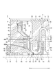
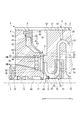
- FIG. 1 It is sectional drawing which shows schematic structure of the centrifugal compressor which concerns on 1st Embodiment of this invention. It is sectional drawing which shows the periphery of the suction flow path of the centrifugal compressor of FIG. It is a top view which shows the heat shield of the centrifugal compressor which concerns on 1st Embodiment.
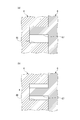
- the state of interference between the shield of the centrifugal compressor of FIG. 1 and the suction-side casing head is shown, (a) shows the state at the time of startup, and (b) shows the state during operation.
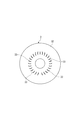
- the flow straightening blade formed in the end surface of the diaphragm of the centrifugal compressor of FIG. 1 is shown from the upstream side.
- FIG. 1 shows the state of interference between the shield of the centrifugal compressor and the rectifying blade in FIG. 1, (a) shows the deformation at the time of startup, shows that the shield and the rectifying blade are deeply interfering, (b ) Represents the deformation at the time of stopping, and shows that the shield and the rectifying blade are shallowly interfering with each other.
- the modification of 1st Embodiment is shown, (a) shows the structure, (b) has shown the mode at the time of starting, (c) has shown the mode in operation. It is sectional drawing which shows the periphery of the suction flow path of the centrifugal compressor which concerns on 2nd Embodiment. Yet another embodiment is shown.
- the centrifugal compressor 1 of this embodiment is used to compress a cryogenic LNG boil-off gas (fluid F).
- the centrifugal compressor 1 includes a casing 2 that forms an outer shell thereof, and a rotor 7 that is rotatably supported inside the casing 2.
- the rotor 7 has a shaft 71 extending along the axis C and a plurality of impellers 72 fixed to the outer peripheral surface of the shaft 71.
- the centrifugal compressor 1 includes an oil heater 8 for reducing a temperature difference between the inside and outside of the suction-side casing head 4 in the casing 2, particularly at the beginning of operation, and the suction-side casing head 4.
- a heat shield 6 for suppressing heat transfer between the suction flow path 18 and the suction flow path 18.
- the centrifugal compressor 1 of the present embodiment reduces the flow rate of the heat medium HM supplied to the oil heater 8 by the heat shield 6 and heat shrinks in the vicinity of the suction path of the fluid F at the beginning of operation. It can cope with thermal deformation that occurs during operation.
- a direction in which the axis C of the shaft 71 extends is referred to as an axial direction, and a direction orthogonal to the axis C is referred to as a radial direction.
- the upstream U and the downstream L are specified on the basis of the flow direction of the fluid F to be compressed.
- the upstream U and the downstream L are relative.
- the casing 2 includes a diaphragm 3 that surrounds the impeller 72 from the outer peripheral side, and a suction-side casing head 4 that is disposed on the most upstream side U in the axial direction at a distance from the diaphragm 3.
- a heat shield 6 held by the suction-side casing head 4 and a discharge-side casing head 5 arranged at a distance from the diaphragm 3 at the most downstream side L in the axial direction are provided.
- the diaphragm 3 of this embodiment has shown the structure which arranged the several diaphragm piece 31 in the axial direction as an example. As shown in FIG.
- the diaphragm 3 is provided with a plurality of rectifying blades 33 for rectifying the flow of the fluid F sucked from the suction flow path 18 and flowing it toward the downstream L. Further, as shown in FIG. 1, a suction scroll 25 for sucking the fluid F and a discharge scroll 29 for discharging the fluid F are provided inside the casing 2.
- the head end surface 41 facing the downstream side L of the suction-side casing head 4 is an annular surface extending in the circumferential direction.
- the head end surface 41 is located on the radially outer side, the first flat surface portion 42 that is a surface orthogonal to the axis C, and is located on the radially inner side of the first flat surface portion 42, and the diameter of the head end surface 41 decreases toward the downstream side L.
- a conical first slope portion 43 that is positioned radially inward of the first slope portion 43 and radially inward of the second plane portion 44 and the second plane portion 44 that are orthogonal to the axis C.
- a conical second slope portion 45 having a diameter reduced toward the downstream side L.
- the suction-side casing head 4 has a key groove 46 into which the key 67 is inserted at a position facing the key 67 of the first flat surface portion 42.
- the combination of the key 67 and the key groove 46 corresponds to the locking structure of the present invention.
- the key groove 46 has a radial dimension larger than the difference in thermal expansion between the suction-side casing head 4 and the heat shield 6.
- the circumferential dimension of the key groove 46 is such that the key 67 can be inserted without a gap.
- the keyway 46 has an axial dimension (depth) equal to or larger than the key 67 in the same direction (height).
- FIG. 3 the suction-side casing head 4 of the present embodiment has four key grooves 46A, a key groove 46B, a key groove 46C, which are arranged at equal intervals by shifting the phase by 90 degrees in the circumferential direction.
- a key groove 46D is provided.
- the four key grooves 46A to 46D are provided concentrically. When there is no need to distinguish the key grooves 46A to 46D, they may be simply referred to as the key grooves 46. The same applies to keys 67A to 67D described later.
- a dry gas seal 16 is provided inside the suction side casing head 4 in the radial direction.
- the dry gas seal 16 is provided on the downstream side L of the first journal bearing 13.
- the dry gas seal 16 is a sealing device that hermetically seals the periphery of the shaft 71 by ejecting a gas such as dry gas.
- a seal fin 17 having a plurality of fins is provided on the downstream side L of the dry gas seal 16.
- the sealing device is not limited to the dry gas seal 16, and a device that can seal the gap between the suction-side casing head 4 and the shaft 71 can be used as appropriate.
- a labyrinth seal may be installed as a sealing device between the suction-side casing head 4 and the shaft 71.
- a large temperature difference suddenly occurs inside and outside the suction side casing head 4 at the beginning of operation and the suction side casing head 4 is thermally contracted, the sealing state by these sealing devices may be deteriorated. Therefore, in this embodiment, by providing the oil heater 8 described later and the heat shield 6, a large temperature difference is avoided at the beginning of operation.
- the suction side casing head 4 includes an oil heater 8 that is a temperature control mechanism for heating the suction side casing head 4.
- the oil heater 8 is provided to adjust the temperature inside and outside the centrifugal compressor 1, particularly to reduce the temperature difference when the centrifugal compressor 1 is started.
- the oil heater 8 has a pipe line 81 formed inside the suction-side casing head 4 and an oil heater body 82 connected to the pipe line 81.
- the heat medium HM is circulated through the oil heater main body 82.
- the pipe line 81 is connected to a supply source of the heat medium HM.
- the oil heater main body 82 has an annular shape and is formed so as to surround the shaft 71 as shown in FIG.
- the oil heater main body 82 is formed with a heat medium flow path 83 through which the heat medium HM supplied via the pipe line 81 circulates.
- the oil heater 8 can be supplied with the same lubricating oil as that supplied to the first journal bearing 13 and the second journal bearing 14 (FIG. 1) as the heat medium HM.
- the heat shield 6 is a plate-like member having an annular shape in plan view, and has an outer diameter side and an inner diameter side. 2 and 3, the heat shield 6 includes a holding portion 61 positioned on the outer diameter side, a first disc portion 62 formed on one side in the axial direction of the holding portion 61, A first conical portion 63 connected to the inner diameter side from the disc portion 62, a second disc portion 64 connected to the inner side in the radial direction from the first conical portion 63, and the radial direction of the second disc portion 64 And a second conical portion 65 connected to the inside.
- the main surfaces of the first disc portion 62 and the second disc portion 64 are orthogonal to the axis C.
- the first conical portion 63 and the second conical portion 65 have a conical shape with a diameter decreasing toward the downstream side L.
- the holding portion 61 contacts the first flat surface portion 42 when the key 67 is inserted into the key groove 46.
- the holding portion 61 is an annular portion that extends in the circumferential direction.
- the holding part 61 includes a key 67 on the surface facing the suction-side casing head 4.
- the key 67 is formed so as to protrude from the holding portion 61 to the upstream side U.
- the heat shield 6 of this embodiment has four keys 67A, 67B, 67C, and 67D that are arranged at equal intervals by shifting the phase by 90 degrees in the circumferential direction. ing.
- the four keys 67A to 67D are provided concentrically.
- the heat shield 6 is held by the suction-side casing head 4 by inserting the keys 67A to 67D into the key grooves 46A to 46D.
- the heat shield 6 when the key 67 is inserted into the key groove 46, the heat shield 6 is positioned in the circumferential direction on the first flat surface portion 42 of the suction side casing head 4 via the holding portion 61. Held in. In this state, the heat shield 6 has a cantilever structure that is held by the first flat portion 42 only by the holding portion 61. That is, the inner diameter end of the heat shield 6 forms a free end FE, and a gap G is provided between the free end FE of the heat shield 6 and the outer peripheral surface of the shaft 71. Since the inner diameter side of the heat shield 6 is the free end FE, the heat shield 6 undergoes thermal expansion and contraction in the radial direction without being particularly restricted.
- the key 67 displaces the inside of the key groove 46 in the radial direction in accordance with thermal expansion and thermal contraction in the radial direction of the heat shield 6 or thermal expansion and thermal contraction in the radial direction of the suction side casing head 4. That is, as shown in FIG. 4A, the suction-side casing head 4 heated by the oil heater 8 is more thermally expanded in the radial direction than the heat shield 6 with the key 67 inserted into the key groove 46. If it is larger, the key groove 46 is displaced radially outward. As a result, as shown in FIG. 4B, the key 67 is displaced relatively toward the inner diameter of the key groove 46.
- the suction side casing head 4 heated by the oil heater 8 has a larger thermal expansion in the radial direction than the heat shield 6. Therefore, the key 67 is inserted into the key groove 46 so that the inside of the key groove 46 can be displaced relatively toward the inner diameter during the operation of the centrifugal compressor 1.
- the heat insulating space 11 is filled with a heat insulating material 69 that makes it difficult to transfer the heat of the heat shield 6 to the suction-side casing head 4.
- the heat insulating space 11 does not necessarily need to be filled with the heat insulating material 69.
- the heat shield 6 is provided with an interference maintaining groove 66 at a position corresponding to each of a plurality of rectifying blades 33 (described later) provided on the diaphragm 3.
- the plurality of interference maintaining grooves 66 are formed so as to penetrate the front and back of the second disc portion 64 with a predetermined interval in the circumferential direction of the second disc portion 64.
- the interference maintaining groove 66 is inserted so that a substantial gap does not occur, and the opening area thereof is preferably determined so that the rectifying blade 33 can slide with little load.
- the interference maintaining groove 66 penetrates the front and back of the second disc portion 64 is shown, but if the interference between the heat shield 6 and the rectifying blade 33 can be maintained, the interference maintaining groove 66 is not necessarily provided. It is not necessary to penetrate the front and back of the heat shield 6.
- the rectifying blade 33 rectifies the flow of the fluid F sucked from the suction flow path 18 and flows it toward the downstream L. As shown in FIG. 2, the rectifying blade 33 is formed so as to protrude from the end face 32 of the diaphragm 3 provided on the most upstream side U to the upstream side U. In the present embodiment, as shown in FIG. 5, the plurality of rectifying blades 33 are provided at predetermined intervals in the circumferential direction of the end surface 32. Note that the rectifying blade 33 can be formed integrally with the diaphragm 3 by cutting, for example, or can be formed separately from the diaphragm 3 and can be joined and fixed to the end face 32 by an appropriate means.
- the tip of the rectifying blade 33 is inserted into the interference maintaining groove 66 as shown in FIG. Regardless of the operation state of the centrifugal compressor 1, the relationship that the tip of the rectifying blade 33 is inserted into the interference maintaining groove 66 is always maintained. Specifically, even if the rectifying blade 33 is most displaced in the direction X away from the heat shield 6, the tip of the rectifying blade 33 is inserted into the interference maintaining groove 66 of the heat shield 6 as shown in FIG.
- the length of the rectifying blade 33 and the depth of the interference maintaining groove 66 are set so as to stay. As will be described later, the rectifying blade 33 moves back and forth in the direction of the axis C inside the interference maintaining groove 66, and the depth of insertion into the interference maintaining groove 66 varies.
- the rotor 7 includes a shaft 71 that extends along the axis C, and a plurality of impellers 72 that are fixed to the outer peripheral surface of the shaft 71.
- the shaft 71 is disposed coaxially with the casing 2 inside the cylindrical casing 2.
- a first journal bearing 13 that is a bearing device that rotatably supports an end portion on the upstream U side of the shaft 71 is provided inside the suction-side casing head 4 in the radial direction.
- a thrust bearing 15 that supports the end portion on the upstream side U of the shaft 71 is provided.
- the first journal bearing 13 is fixed inside the suction side casing head 4, and the thrust bearing 15 is fixed outside the suction side casing head 4.
- a second journal bearing 14 that rotatably supports an end portion of the downstream side L of the shaft 71 is provided inside the discharge-side casing head 5 in the radial direction.
- the second journal bearing 14 is fixed inside the discharge-side casing head 5.
- each impeller 72 includes a substantially disc-shaped hub 73 whose diameter gradually increases toward the downstream side L, and a plurality of blades 74 that are radially attached to the hub 73 and arranged in the circumferential direction.
- the shroud 75 is attached so as to cover the distal ends of the plurality of blades 74 in the circumferential direction.
- a six-stage impeller 72 is provided is shown here, the present invention can be applied to a centrifugal compressor including at least a single-stage impeller 72.
- the fluid flow path 12 formed inside the casing 2 is mainly configured by a suction flow path 18, a diffuser passage 27, a return passage 28, and a discharge flow path 19.
- the suction flow path 18 is provided at the end of the upstream U side of the casing 2 in order to guide the fluid F from the outside to the inside of the casing 2.
- the suction flow path 18 is formed between the heat shield 6 and the diaphragm 3 as shown in FIG. That is, the upstream U of the suction flow path 18 is partitioned by the heat shield 6 held by the suction casing head 4, and the downstream L of the suction flow path 18 is partitioned by the end face 32 of the diaphragm 3.
- a heat insulating space 11 is formed between the heat shield 6 and the suction side casing head 4.
- the diffuser passage 27 and the return passage 28 are provided for flowing the fluid F from the upstream U toward the downstream L.
- an internal space 21 that communicates with each of the suction flow path 18 and the discharge flow path 19 and repeats diameter reduction and diameter expansion is provided inside the casing 2.
- the internal space 21 functions as a space for accommodating the impeller 72, and the space excluding the impeller 72 functions as the diffuser passage 27 and the return passage 28.
- the suction flow path 18 and the discharge flow path 19 communicate with each other via the impeller 72 and the fluid flow path 12.
- the discharge channel 19 is provided at the end on the downstream side L of the casing 2 in order to allow the fluid F to flow out.
- the discharge channel 19 is formed between the discharge-side shielding member 84 and the diaphragm 3.
- the fluid flow path 12 is adjacent to the downstream side L while meandering in the radial direction inside the casing 2 by forming the diffuser passages 27 and the return passages 28 alternately. It is formed so as to connect between the impellers 72 and 72.
- the fluid F is compressed in stages each time it passes through the plurality of impellers 72 while flowing through the fluid flow path 12.
- the centrifugal compressor 1 has the following effects. Since the centrifugal compressor 1 includes the oil heater 8, the suction-side casing head 4 can be heated or cooled by selecting the temperature of the heat medium HM to be supplied. Therefore, when the cryogenic fluid F is compressed by the centrifugal compressor 1, the inside and outside of the centrifugal compressor 1, specifically, the inside and outside of the suction-side casing head 4 are supplied by supplying the high-temperature heat medium HM. Temperature difference can be reduced.
- the centrifugal compressor 1 can suppress heat transfer between the suction-side casing head 4 and the suction flow path 18 by providing the heat shield 6 between the suction-side casing head 4 and the suction flow path 18. it can. Therefore, when the cryogenic fluid F is compressed, a decrease in the temperature of the suction-side casing head 4 due to the fluid F can be suppressed, so that the flow rate of the heat medium HM supplied to the oil heater 8 can be reduced. Moreover, since the centrifugal compressor 1 is provided with the heat insulating space 11 between the suction-side casing head 4 and the heat shield 6, heat transfer between the fluid F and the suction-side casing head 4 can be further suppressed. .
- the centrifugal compressor 1 can perform centrifugal compression even when the fluid F having a large temperature difference from the normal temperature is to be compressed.
- the temperature difference between the inside and outside of the machine 1 can be suppressed.
- problems such as a sealing device in the vicinity of the suction flow path 18 of the centrifugal compressor 1 due to thermal deformation that may occur at the beginning of operation with a smaller flow rate of the heat medium HM.
- the centrifugal compressor 1 is provided with a structure for dealing with the difference between these thermal expansion and thermal contraction.
- the heat shield 6 and the suction-side casing head 4 are fixed by fastening using, for example, bolts, and relative displacement between the heat shield 6 and the suction-side casing head 4 is not allowed.
- a different structure is assumed. In this structure, if there is a difference in thermal expansion between the heat shield 6 and the suction-side casing head 4, one of them restrains thermal expansion in the other radial direction, and thermal stress is generated.
- the centrifugal compressor 1 compresses the cryogenic fluid F
- the radial expansion of the suction-side casing head 4 heated by the oil heater 8 is larger than that of the heat shield 6, so that a large amount of heat is applied to the fastening portion. Stress is generated.
- the key 67 that is a locking projection provided on the heat shield 6 is a key groove 46 that is a locking groove provided on the suction side casing head 4.
- the suction-side casing head 4 and the heat shield 6 are locked to each other so as to allow relative displacement in the radial direction. That is, even if the thermal expansion in the radial direction of the suction side casing head 4 is larger than that of the heat shield 6, the key 67 is displaced radially in the key groove 46 as shown in FIG. Thus, generation of thermal stress can be suppressed.
- the suction side casing head 4 is provided with the key groove 46 and the heat shield 6 is provided with the key 67.
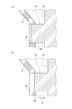
- the key and the key groove are provided in reverse. That is, as shown in FIG. 7A, the heat shield 6 is formed with a key groove 68 penetrating the front and back.
- a key 47 is formed on the suction side casing head 4 so as to protrude from the first flat surface portion 42 to the downstream side L.
- the key 47 is inserted into the key groove 68 as shown in FIG.
- the key 47 and the key groove 68 correspond to the locking structure of the present invention.
- the key 47 when the suction-side casing head 4 is thermally expanded in the radial direction relative to the heat shield 6, the key 47 is displaced radially outside in the key groove 68 as shown in FIG. 7C.
- a key 67 and a key groove 68 are formed on the heat shield 6, and a key groove 46 and a key 47 are formed on the suction side casing head 4 so as to correspond to the key 67 and the key groove 68 of the heat shield 6. It may be.
- a second embodiment of the present invention will be described with reference to FIG.
- the same components as those in the first embodiment are denoted by the same reference numerals as those in the first embodiment, and description thereof is omitted.
- a key groove 46 is provided in the suction-side casing head 4 and a key 67 is provided in the heat shield 6.
- the pin that is a locking protrusion on the heat shield 6. P is detachably installed.
- the pin P is a part that contacts the suction-side casing head 4 inside the key groove 46, it is sufficient to replace the pin P even if the pin P is worn.
- four pairs of keys 67 and key grooves 46 are provided at equal intervals by shifting the phase by 90 degrees in the circumferential direction, but the present invention is not limited to this.
- three pairs of keys 67 and key grooves 46 may be provided at equal intervals by shifting the phase by 120 degrees in the circumferential direction, as shown in FIG. 9B.
- two may be provided on the same straight line.
- the suction-side casing head 4 and the heat shield 6 are locked to each other so as to allow relative displacement in the radial direction, the pair of keys 67 and the key groove 46 are even in the circumferential direction. It does not have to be provided at a particular interval.
- the configuration of the oil heater 8 and the configuration of the heat shield 6 are merely examples of the present invention, and the configurations thereof are arbitrary as long as the effect of reducing the temperature difference between the inside and the outside is obtained. Further, the method of maintaining the interference state between the rectifying blade and the heat shield is the same, and the configuration thereof is arbitrary as long as the rectifying effect of the rectifying blade can be ensured.
- the rectifying blade 33 can be provided on the heat shield 6 side
- the interference maintaining groove 66 can be provided on the end face 32 side of the diaphragm 3.
Landscapes
- Engineering & Computer Science (AREA)
- Mechanical Engineering (AREA)
- General Engineering & Computer Science (AREA)
- Physics & Mathematics (AREA)
- Thermal Sciences (AREA)
- Structures Of Non-Positive Displacement Pumps (AREA)
Abstract
本発明に係る遠心圧縮機1は、ケーシング2の内部に回転可能に配置されるシャフト71と、シャフト71の外周に固定されるインペラ72と、を有するロータ7と、インペラ72を外周側から囲うダイアフラム3と、流体Fが吸い込まれる側において、ダイアフラム3と間隔を空けて配置される吸込側ケーシングヘッド4と、吸込側ケーシングヘッド4の内部に設けられる、熱媒体の流通により周囲の温度調整を行うオイルヒータ8と、吸込側ケーシングヘッド4とダイアフラム3の間に配置される遮熱体6と、遮熱体6と吸込側ケーシングヘッド4が、相対的な径方向への変位が許容されるように互いに係止される係止構造と、を備える。
Description
本発明は、インペラを用いて流体を圧縮する遠心圧縮機に関する。
工業プロセス及びプロセスプラントにおいて使用される遠心圧縮機は、回転するインペラの径方向に空気、ガスなどの流体を通り抜けさせ、その際に発生する遠心力を利用して流体を圧縮する。遠心圧縮機は、ケーシングと、ケーシングの内部に収容されるロータと、を基本的な構成として備える。ロータは、ケーシングに回転可能に配置されるシャフトと、シャフトの外周面に固定される複数枚のインペラと、を備えている。
遠心圧縮機は、単一のインペラによる単段式のものと、複数のインペラを回転軸線の方向に直列に並べた多段式のものに区分できるが、後者の多段式の遠心圧縮機が多用されている。
遠心圧縮機は、単一のインペラによる単段式のものと、複数のインペラを回転軸線の方向に直列に並べた多段式のものに区分できるが、後者の多段式の遠心圧縮機が多用されている。
遠心圧縮機の圧縮対象として、例えば特許文献1に記載されるように、ボイルオフガス(Boil Off Gas:BOG)が知られている。例えば、LNG(Liquefied Natural Gas 液化天然ガス)のボイルオフガスは、極低温の流体である。この遠心圧縮機は、特に運転の開始当初に、ガスの吸込流路の近傍は極低温にさらされるのに対して、圧縮機の外周面は大気温度にさらされるので、大きな温度差が生ずる。そうすると、構成要素の収縮に伴う熱応力が吸込流路の近傍に生じる。遠心圧縮機の内外の温度差を軽減するために、特許文献1は、熱媒体としてのオイルにより吸込流路の近傍を加熱することを提案する。
ところが、オイルによる加熱だけで遠心圧縮機の内外の温度差を軽減するには、多量のオイルが必要であり、そのための付帯設備、機器によるコスト上昇が無視できなくなる。
一方で、遠心圧縮機の外殻をなす車室とその内側に設けられる内部品は、熱容量の違いに基づいて熱応答性が相違する。したがって、遠心圧縮機の起動から定常運転の間と、定常運転から停止の間で、熱変形(または、熱膨張)が相違することを考慮する必要がある。
一方で、遠心圧縮機の外殻をなす車室とその内側に設けられる内部品は、熱容量の違いに基づいて熱応答性が相違する。したがって、遠心圧縮機の起動から定常運転の間と、定常運転から停止の間で、熱変形(または、熱膨張)が相違することを考慮する必要がある。
以上より、本発明は、運転開始当初におけるガスの吸込流路の近傍の熱収縮を少ない流量の熱媒体で低減できるのに加えて、運転の過程に生じる熱変形にも対応できる遠心圧縮機を提供することを目的とする。
本発明の遠心圧縮機は、ケーシングの内部に回転可能に配置されるシャフトと、シャフトの外周に固定されるインペラと、を有するロータと、インペラを外周側から囲うダイアフラムと、流体が吸い込まれる側において、ダイアフラムと間隔を空けて配置される吸込側ケーシングヘッドと、吸込側ケーシングヘッドの内部に設けられる、熱媒体の流通により周囲の温度調整を行う温調機構と、吸込側ケーシングヘッドとダイアフラムの間に配置される遮熱体と、遮熱体と吸込側ケーシングヘッドが、相対的な径方向への変位が許容されるように互いに係止される係止構造と、を備えることを特徴とする。
係止構造は、吸込側ケーシングヘッドと遮熱体の一方に設けられる係止突起と、吸込側ケーシングヘッドと遮熱体の他方に設けられる、係止突起が挿入される係止溝と、を備えることが好ましい。
係止突起は、吸込側ケーシングヘッドと遮熱体の一方に、一体的に設けられるか、又は、別体として設けられることが好ましい。
遮熱体と吸込側ケーシングヘッドが相対的な径方向への変位をする際に、係止突起が係止溝の中で摺動することが好ましい。
複数の係止構造が、吸込側ケーシングヘッドと遮熱体が互いに対向する面に、放射状に設けられることが好ましい。
特に、複数の係止構造が、円周方向に均等な間隔を空けて設けられることが好ましい。
特に、複数の係止構造が、円周方向に均等な間隔を空けて設けられることが好ましい。
本発明の遠心圧縮機によれば、吸込流路を区画する遮蔽体を設けることで、運転開始当初におけるガスの吸込流路の近傍の熱収縮を低減させることができる。さらに、本発明の遠心圧縮機によれば、遮熱体と吸込側ケーシングヘッドとの相対的な径方向への変位が許容されていることで、起動から定常運転に至り、さらに停止までの運転の過程を通じて、吸込側ケーシングヘッドと遮熱体の熱変形の差に対応できる。
〔第1実施形態〕
以下、添付図面を参照しながら、本発明の実施形態について説明する。
本実施形態では、遠心圧縮機の一例として、複数のインペラを備える多段式の遠心圧縮機を例に挙げて説明する。
以下、添付図面を参照しながら、本発明の実施形態について説明する。
本実施形態では、遠心圧縮機の一例として、複数のインペラを備える多段式の遠心圧縮機を例に挙げて説明する。
本実施形態の遠心圧縮機1は、極低温のLNGのボイルオフガス(流体F)を圧縮するのに用いられる。
遠心圧縮機1は、図1に示すように、その外殻を形成するケーシング2と、ケーシング2の内部で回転自在に支持されるロータ7と、を備えている。ロータ7は、軸線Cに沿って延びるシャフト71と、シャフト71の外周面に固定される複数のインペラ72と、を有している。遠心圧縮機1は、ケーシング2に、特に運転開始当初に、吸込側ケーシングヘッド4の内外の温度差を軽減するためのオイルヒータ8と、吸込側ケーシングヘッド4
と吸込流路18の間の熱伝達を抑えるための遮熱体6を備えている。
遠心圧縮機1は、図1に示すように、その外殻を形成するケーシング2と、ケーシング2の内部で回転自在に支持されるロータ7と、を備えている。ロータ7は、軸線Cに沿って延びるシャフト71と、シャフト71の外周面に固定される複数のインペラ72と、を有している。遠心圧縮機1は、ケーシング2に、特に運転開始当初に、吸込側ケーシングヘッド4の内外の温度差を軽減するためのオイルヒータ8と、吸込側ケーシングヘッド4
と吸込流路18の間の熱伝達を抑えるための遮熱体6を備えている。
本実施形態の遠心圧縮機1は、遮熱体6により、オイルヒータ8に供給する熱媒体HMの流量を低減し、かつ、運転開始当初における流体Fの吸込流路の近傍の熱収縮、及び運転の過程に生じる熱変形に対応できる。
以下、遠心圧縮機1の各要素について説明する。
なお、遠心圧縮機1において、シャフト71の軸線Cが延びている方向を軸線方向と称し、また、軸線Cに直交する方向を径方向と称する。また、遠心圧縮機1において、図1に示すように、圧縮の対象となる流体Fの流れる向きを基準にして、上流側U及び下流側Lを特定する。なお、上流側U及び下流側Lは相対的なものである。
以下、遠心圧縮機1の各要素について説明する。
なお、遠心圧縮機1において、シャフト71の軸線Cが延びている方向を軸線方向と称し、また、軸線Cに直交する方向を径方向と称する。また、遠心圧縮機1において、図1に示すように、圧縮の対象となる流体Fの流れる向きを基準にして、上流側U及び下流側Lを特定する。なお、上流側U及び下流側Lは相対的なものである。
[ケーシング2]
ケーシング2の内部には、図1に示すように、インペラ72を外周側から囲うダイアフ
ラム3と、軸線方向の最も上流側Uに、ダイアフラム3と間隔をあけて配置される吸込側ケーシングヘッド4と、吸込側ケーシングヘッド4に保持される遮熱体6と、軸線方向の最も下流側Lに、ダイアフラム3と間隔をあけて配置される排出側ケーシングヘッド5と、が備えられている。
本実施形態のダイアフラム3は、一例として複数のダイアフラム片31を軸線方向に配列した構成を示している。ダイアフラム3は、吸込流路18から吸込まれた流体Fの流れを整流にして下流側Lに向けて流すために、図5に示すように、複数の整流翼33が設けられている。
さらに、ケーシング2の内部には、図1に示すように、流体Fを吸込ための吸込スクロール25と流体Fを吐出するための吐出スクロール29が設けられている。
[吸込側ケーシングヘッド4]
図2に示すように、吸込側ケーシングヘッド4の下流側Lを向くヘッド端面41は、周方向に延在する環状の面である。ヘッド端面41は、径方向外側に位置し、軸線Cに直交する面である第一平面部42と、第一平面部42より径方向の内側に位置し、下流側Lに向かうのに従って縮径する円錐状の第一斜面部43と、第一斜面部43より径方向の内側に位置し、軸線Cに直交する面である第二平面部44と第二平面部44より径方向の内側に位置し、下流側Lに向かうのに従って縮径する円錐状の第二斜面部45とを有している。
図2に示すように、吸込側ケーシングヘッド4の下流側Lを向くヘッド端面41は、周方向に延在する環状の面である。ヘッド端面41は、径方向外側に位置し、軸線Cに直交する面である第一平面部42と、第一平面部42より径方向の内側に位置し、下流側Lに向かうのに従って縮径する円錐状の第一斜面部43と、第一斜面部43より径方向の内側に位置し、軸線Cに直交する面である第二平面部44と第二平面部44より径方向の内側に位置し、下流側Lに向かうのに従って縮径する円錐状の第二斜面部45とを有している。
吸込側ケーシングヘッド4は、図1及び図2に示すように、第一平面部42のキー67と対向する位置に、キー67が挿入されるキー溝46を有している。キー67とキー溝46の組み合わせが、本発明の係止構造に対応する。
キー溝46は、径方向の寸法が、吸込側ケーシングヘッド4と遮熱体6の熱膨張の差よりも大きい。
また、キー溝46の周方向の寸法は、キー67が隙間なく挿入される程度の大きさを有している。
キー溝46は、軸方向の寸法(深さ)がキー67の同方向の寸法(高さ)以上である。このため、キー溝46の奥までキー67が挿入されても、保持部61が第一平面部42と接触できる。
本実施形態の吸込側ケーシングヘッド4は、図3に示すように、周方向に90度だけ位相をずらして均等な間隔に配列される、4つのキー溝46A、キー溝46B、キー溝46C、キー溝46Dを有している。4つのキー溝46A~46Dは、同心円状に設けられる。
なお、キー溝46A~46Dを区別する必要がない場合には、単にキー溝46ということがある。後述するキー67A~67Dについても同様である。
吸込側ケーシングヘッド4の径方向の内側には、図1に示すように、ドライガスシール
16が設けられている。ドライガスシール16は、第一ジャーナル軸受13よりも下流側Lに設けられている。ドライガスシール16は、ドライガスなどの気体を噴出させることによって、シャフト71の周囲を気密に封止するシール装置である。加えて、ドライガスシール16よりも下流側Lには、複数のフィンを有するシールフィン17が設けられている。
なお、シール装置としては、ドライガスシール16に限らず、吸込側ケーシングヘッド4とシャフト71との間の隙間をシールできるものを適宜採用することができる。例えば、吸込側ケーシングヘッド4とシャフト71との間に、シール装置としてラビリンスシールを設置してもよい。
ここで、運転開始当初に吸込側ケーシングヘッド4の内外で大きな温度差が急激に生じて、吸込側ケーシングヘッド4が熱収縮すると、これらシール装置によるシール状態が劣化することがある。そこで本実施形態は、後述するオイルヒータ8を設けるとともに、遮熱体6を設けることにより、運転開始当初に大きな温度差が生じるのを避ける。
吸込側ケーシングヘッド4は、図1に示すように、吸込側ケーシングヘッド4を加熱する温調機構であるオイルヒータ8を備えている。オイルヒータ8は、遠心圧縮機1の運転開始の際に、その内外の温度調整、特に温度差を軽減するために設けられている。オイルヒータ8は、図2に示すように、吸込側ケーシングヘッド4の内部に形成される管路81と、管路81と接続されたオイルヒータ本体82とを有し、管路81を介してオイルヒータ本体82に熱媒体HMが流通される。
管路81は、熱媒体HMの供給源と接続される。オイルヒータ本体82は環状をなし、図2に示すように、シャフト71を囲うように形成される。オイルヒータ本体82には、管路81を介して供給される熱媒体HMが循環する熱媒体流路83が形成される。例えば、オイルヒータ8には、熱媒体HMとして第一ジャーナル軸受13,第二ジャーナル軸受14(図1)に供給するのと同じ潤滑油を供給することができる。熱媒体HMの温度を変更することによって、吸込側ケーシングヘッド4を加熱する温度を変更したり、場合によっては吸込側ケーシングヘッド4を冷却したりすることができる。
[遮熱体6]
遮熱体6は、図3に示すように、平面視した形状が円環状の板状部材であり、外径側と内径側を有している。遮熱体6は、図2及び図3に示すように、外径側に位置する保持部61と、保持部61の軸方向の一方側に形成される第一円板部62と、第一円板部62より内径側に接続される第一円錐部63と、第一円錐部63より径方向の内側に接続される第二円板部64と、第二円板部64の径方向の内側に接続される第二円錐部65と、を有している。
第一円板部62と第二円板部64の各々の主面は、軸線Cと直交する。第一円錐部63及び第二円錐部65は、下流側Lに向かうのに従って縮径する円錐状をなしている。
遮熱体6は、図3に示すように、平面視した形状が円環状の板状部材であり、外径側と内径側を有している。遮熱体6は、図2及び図3に示すように、外径側に位置する保持部61と、保持部61の軸方向の一方側に形成される第一円板部62と、第一円板部62より内径側に接続される第一円錐部63と、第一円錐部63より径方向の内側に接続される第二円板部64と、第二円板部64の径方向の内側に接続される第二円錐部65と、を有している。
第一円板部62と第二円板部64の各々の主面は、軸線Cと直交する。第一円錐部63及び第二円錐部65は、下流側Lに向かうのに従って縮径する円錐状をなしている。
保持部61は、図2に示すように、キー67がキー溝46に挿入されると、第一平面部42と当接する。保持部61は、周方向に延在する環状の部位である。
保持部61は、吸込側ケーシングヘッド4と対向する面に、キー67を備えている。キー67は、保持部61から上流側Uに突出するように形成されている。
本実施形態の遮熱体6は、図3に示すように、周方向に90度だけ位相をずらして均等な間隔に配列される4つのキー67A、キー67B、キー67C、キー67Dを有している。4つのキー67A~67Dは、同心円状に設けられる。
遮熱体6は、キー67A~67Dが、キー溝46A~46Dに挿入されることにより、吸込側ケーシングヘッド4に保持される。
保持部61は、吸込側ケーシングヘッド4と対向する面に、キー67を備えている。キー67は、保持部61から上流側Uに突出するように形成されている。
本実施形態の遮熱体6は、図3に示すように、周方向に90度だけ位相をずらして均等な間隔に配列される4つのキー67A、キー67B、キー67C、キー67Dを有している。4つのキー67A~67Dは、同心円状に設けられる。
遮熱体6は、キー67A~67Dが、キー溝46A~46Dに挿入されることにより、吸込側ケーシングヘッド4に保持される。
遮熱体6は、図2に示すように、キー67がキー溝46に挿入されると、保持部61を
介して吸込側ケーシングヘッド4の第一平面部42に周方向に位置決めされた状態で保持される。遮熱体6は、この状態で、保持部61のみによって第一平面部42に保持される片持ち構造をなしている。つまり、遮熱体6の内径端は自由端FEをなしており、遮熱体6の自由端FEとシャフト71の外周面との間には隙間Gが設けられている。遮熱体6の内径側が自由端FEとなっているために、格別な拘束を受けることなく、遮熱体6は径方向への熱膨張及び熱収縮が生じる。
キー67は、遮熱体6の径方向への熱膨張及び熱収縮又は、吸込側ケーシングヘッド4の径方向への熱膨張及び熱収縮に伴い、キー溝46の内部を径方向に変位する。つまり、図4(a)に示すように、キー67がキー溝46に挿入された状態で、オイルヒータ8により加熱された吸込側ケーシングヘッド4が遮熱体6よりも径方向の熱膨張が大きければ、キー溝46が径方向の外側に変位する結果、図4(b)に示すように、キー67がキー溝46の内部を相対的に内径に向けて変位する。
オイルヒータ8により加熱された吸込側ケーシングヘッド4の方が遮熱体6よりも径方向の熱膨張が大きい。そこで、遠心圧縮機1の運転中に、キー67がキー溝46の内部を相対的に内径に向けて変位できるように、キー溝46に挿入されている。
遮熱体6と吸込側ケーシングヘッド4のヘッド端面41との間には、図2に示すように、断熱空間11として機能する環状の空間が形成される。
断熱空間11には、遮熱体6の熱を吸込側ケーシングヘッド4に伝達し難くする断熱材69が隙間なく充填される。ただし、断熱空間11は、必ずしも断熱材69が充填される必要はない。
断熱空間11には、遮熱体6の熱を吸込側ケーシングヘッド4に伝達し難くする断熱材69が隙間なく充填される。ただし、断熱空間11は、必ずしも断熱材69が充填される必要はない。
遮熱体6は、図3に示すように、ダイアフラム3に設けられた後述する複数の整流翼33のそれぞれに対応する位置に、干渉維持溝66が設けられている。複数の干渉維持溝66は、第二円板部64の円周方向に所定の間隔を空けて、第二円板部64の表裏を貫通するように形成されている。干渉維持溝66は、整流翼33が実質的な隙間が生じないように挿入され、好ましくは負荷をほとんど受けることなく摺動できるように、その開口面積が定められる。
なお、ここでは干渉維持溝66が第二円板部64の表裏を貫通する例を示しているが、遮熱体6と整流翼33の干渉を維持できるのであれば、必ずしも干渉維持溝66が遮熱体6の表裏を貫通しなくてもよい。
なお、ここでは干渉維持溝66が第二円板部64の表裏を貫通する例を示しているが、遮熱体6と整流翼33の干渉を維持できるのであれば、必ずしも干渉維持溝66が遮熱体6の表裏を貫通しなくてもよい。
[整流翼33]
整流翼33は、吸込流路18から吸込まれた流体Fの流れを整流にして下流側Lに向けて流す。
整流翼33は、図2に示すように、最も上流側Uに設けられるダイアフラム3の端面32から上流側Uに突出するように形成されている。
本実施形態は、複数の整流翼33が、図5に示すように、端面32の円周方向に所定の間隔をあけて設けられている。なお、整流翼33は、例えば削り出しにより、ダイアフラム3と一体的に形成することができるし、ダイアフラム3とは別体として作製しておき、端面32に適宜の手段により接合して固定できる。
整流翼33は、吸込流路18から吸込まれた流体Fの流れを整流にして下流側Lに向けて流す。
整流翼33は、図2に示すように、最も上流側Uに設けられるダイアフラム3の端面32から上流側Uに突出するように形成されている。
本実施形態は、複数の整流翼33が、図5に示すように、端面32の円周方向に所定の間隔をあけて設けられている。なお、整流翼33は、例えば削り出しにより、ダイアフラム3と一体的に形成することができるし、ダイアフラム3とは別体として作製しておき、端面32に適宜の手段により接合して固定できる。
整流翼33の先端は、図2に示すように、干渉維持溝66に挿入されている。遠心圧縮機1の運転状態にかかわらず、整流翼33の先端が干渉維持溝66に挿入されるという関係は、常に維持される。具体的には、整流翼33が遮熱体6から離れる向きXに最も変位したとしても、図6(b)に示すように、整流翼33の先端が遮熱体6の干渉維持溝66に留まるように、整流翼33の長さ、及び、干渉維持溝66の深さが設定される。なお、後述するように、整流翼33は、干渉維持溝66の内部において、軸線Cの方向に進退移動し、干渉維持溝66に挿入される深さが変動する。
[ロータ7]
ロータ7は、図1に示すように、軸線Cに沿って延びるシャフト71と、シャフト71の外周面に固定される複数のインペラ72と、を備える。
ロータ7は、図1に示すように、軸線Cに沿って延びるシャフト71と、シャフト71の外周面に固定される複数のインペラ72と、を備える。
[シャフト71]
シャフト71は、図1に示すように、円筒状の形態のケーシング2の内部に、ケーシング2と同軸上に配置される。
具体的には、吸込側ケーシングヘッド4の径方向の内側には、シャフト71の上流側Uの端部を回転可能に支持する軸受装置である第一ジャーナル軸受13が設けられている。さらに、第一ジャーナル軸受13よりも上流側Uには、シャフト71の上流側Uの端部を支持するスラスト軸受15が設けられている。第一ジャーナル軸受13は、吸込側ケーシングヘッド4の内部に固定され、スラスト軸受15は吸込側ケーシングヘッド4の外部に固定されている。
排出側ケーシングヘッド5の径方向の内側には、シャフト71の下流側Lの端部を回転可能に支持する第二ジャーナル軸受14が設けられている。第二ジャーナル軸受14は、排出側ケーシングヘッド5の内部に固定される。
[インペラ72]
インペラ72は、シャフト71とともに回転することで生じる遠心力を利用して上流側Uから下流側Lに向けて流れる流体Fを径方向の外側に向けて圧送する。そのために、図1及び図2に示すように、ケーシング2の内部には、流体Fを上流側Uから下流側Lに向けて流す流体流路12が形成される。
インペラ72は、図1に示すように、軸線方向に間隔を空けて6段配列される。各々のインペラ72は、図2に示すように、下流側Lに進むにつれて漸次径が拡大する略円盤状のハブ73と、ハブ73に放射状に取り付けられ、周方向に並んだ複数の羽根74と、複数の羽根74の先端側を周方向に覆うように取り付けられたシュラウド75と、によって構成される。
なお、ここでは6段のインペラ72を設ける例を示しているが、本発明は少なくとも1段のインペラ72を備える遠心圧縮機に適用できる。
[流体流路12]
次に、ケーシング2の内部に形成される流体流路12について説明する。流体流路12は、図1及び図2に示すように、主に吸込流路18と、デュフューザ通路27と、リターン通路28と、排出流路19によって構成される。
次に、ケーシング2の内部に形成される流体流路12について説明する。流体流路12は、図1及び図2に示すように、主に吸込流路18と、デュフューザ通路27と、リターン通路28と、排出流路19によって構成される。
吸込流路18は、図1に示すように、ケーシング2の上流側Uの端部に、流体Fを外部からケーシング2の内部に導くために設けられている。
吸込流路18は、図2に示すように、遮熱体6とダイアフラム3の間に形成される。つまり、吸込流路18の上流側Uは、吸込側ケーシングヘッド4に保持された遮熱体6によって区画され、吸込流路18の下流側Lは、ダイアフラム3の端面32によって区画される。遮熱体6と吸込側ケーシングヘッド4との間には、断熱空間11が形成される。
吸込流路18は、図2に示すように、遮熱体6とダイアフラム3の間に形成される。つまり、吸込流路18の上流側Uは、吸込側ケーシングヘッド4に保持された遮熱体6によって区画され、吸込流路18の下流側Lは、ダイアフラム3の端面32によって区画される。遮熱体6と吸込側ケーシングヘッド4との間には、断熱空間11が形成される。
デュフューザ通路27とリターン通路28は、流体Fを上流側Uから下流側Lに向けて流すために設けられている。
ケーシング2の内部には、図2に示すように、吸込流路18及び排出流路19のそれぞれに連通し、縮径及び拡径を繰り返す内部空間21が設けられている。内部空間21は、インペラ72を収容する空間として機能するとともに、インペラ72を除く空間がデュフューザ通路27とリターン通路28として機能する。こうして、吸込流路18と排出流路19とは、インペラ72及び流体流路12を介して連通している。
ケーシング2の内部には、図2に示すように、吸込流路18及び排出流路19のそれぞれに連通し、縮径及び拡径を繰り返す内部空間21が設けられている。内部空間21は、インペラ72を収容する空間として機能するとともに、インペラ72を除く空間がデュフューザ通路27とリターン通路28として機能する。こうして、吸込流路18と排出流路19とは、インペラ72及び流体流路12を介して連通している。
排出流路19は、図1に示すように、ケーシング2の下流側Lの端部に、流体Fを外部に流出させるために設けられている。排出流路19は、排出側の遮蔽部材84とダイアフラム3の間に形成される。
流体流路12は、デュフューザ通路27とリターン通路28が交互に形成されていることにより、図1に示すように、ケーシング2の内部において、径方向に蛇行しながら下流側Lに延び、隣接するインペラ72,72の間を繋ぐように形成される。流体Fは、流体流路12を流れながら、複数段のインペラ72を通過する度に段階的に圧縮される。
[遠心圧縮機1の効果]
第1実施形態に係る遠心圧縮機1は、以下の効果を奏する。
遠心圧縮機1は、オイルヒータ8を備えているので、供給する熱媒体HMの温度を選択することにより、吸込側ケーシングヘッド4を加熱し、または、冷却することができる。したがって、遠心圧縮機1により、極低温の流体Fを圧縮する場合には、高い温度の熱媒体HMを供給することにより、遠心圧縮機1の内外、具体的には吸込側ケーシングヘッド4の内外の温度差を軽減できる。
第1実施形態に係る遠心圧縮機1は、以下の効果を奏する。
遠心圧縮機1は、オイルヒータ8を備えているので、供給する熱媒体HMの温度を選択することにより、吸込側ケーシングヘッド4を加熱し、または、冷却することができる。したがって、遠心圧縮機1により、極低温の流体Fを圧縮する場合には、高い温度の熱媒体HMを供給することにより、遠心圧縮機1の内外、具体的には吸込側ケーシングヘッド4の内外の温度差を軽減できる。
また、遠心圧縮機1は、吸込側ケーシングヘッド4と吸込流路18との間に遮熱体6を設けることにより、吸込側ケーシングヘッド4と吸込流路18の間の熱伝達を抑えることができる。したがって、極低温の流体Fを圧縮する場合に、流体Fによる吸込側ケーシングヘッド4の温度の低下を抑えることができるので、オイルヒータ8に供給する熱媒体HMの流量を少なくできる。しかも、遠心圧縮機1は、吸込側ケーシングヘッド4と遮熱体6の間に断熱空間11を設けているので、流体Fと吸込側ケーシングヘッド4の間の熱伝達をより低く抑えることができる。
以上のように、オイルヒータ8を設けるとともに、断熱空間11及び遮熱体6を設けることにより、遠心圧縮機1は、常温と温度差の大きい流体Fを圧縮対象とする場合にも、遠心圧縮機1の内外における温度差を抑えることができる。これにより、特に、運転開始当初に生じ得る熱変形によって遠心圧縮機1の吸込流路18の近傍のシール装置などの不具合を、より少ない熱媒体HMの流量で防止できる。
一方で、遠心圧縮機1の運転を継続していると、今度は、吸込側ケーシングヘッド4、遮熱体6及びダイアフラム3には温度上昇が不可避的に生じる。吸込側ケーシングヘッド4、遮熱体6、ダイアフラム3は、遠心圧縮機1の運転中の温度及び線膨張係数の違いにより、熱膨張及び熱収縮に差が生じる。遠心圧縮機1にはこれらの熱膨張及び熱収縮の差に対応するための構造が設けられている。
ここで、遮熱体6と吸込側ケーシングヘッド4が例えばボルトを用いた締結により固定されており、遮熱体6と吸込側ケーシングヘッド4の間の相対的な変位が許されない、本実施形態とは異なる構造を想定する。この構造は、遮熱体6と吸込側ケーシングヘッド4の熱膨張に差があると、一方が他方の径方向の熱膨張を拘束してしまい、熱応力が発生する。遠心圧縮機1が極低温の流体Fを圧縮すると、オイルヒータ8により加熱された吸込側ケーシングヘッド4の径方向への熱膨張が遮熱体6のそれよりも大きいので、締結部分に大きな熱応力が生じる。
ところが、本実施形態は、図4(a)に示すように、遮熱体6に設けられた係止突起であるキー67が吸込側ケーシングヘッド4に設けられた係止溝であるキー溝46に挿入され、吸込側ケーシングヘッド4と遮熱体6が径方向への相対的な変位が許容されるように互いに係止されている。つまり、吸込側ケーシングヘッド4の径方向への熱膨張が遮熱体6のそれよりも大きくても、図4(b)に示すように、キー67がキー溝46の内部を径方向に変位して、熱応力の発生の抑えることができる。このように、遠心圧縮機1は、その運転が継続されている限り、キー67とキー溝46を備える係止機構により、遮熱体6と吸込側ケーシングヘッド4が互いに係止された状態が維持されるので、吸込側ケーシングヘッド4と吸込流路18の間の熱伝達を安定して抑えることができる。
次に、遮熱体6とダイアフラム3の間の熱変形差に対する対策について説明する。
整流翼33の先端が遮熱体6と当接しているだけでは、ダイアフラム3の熱変形により、整流翼33が遮熱体6から離れる向きに変位すると、遮熱体6と整流翼33の先端の間に隙間が生じるおそれがある。この隙間が生じると、整流翼33による流体Fの整流効果を十分に得ることができなくなる。
ところが、本実施形態は、図6(a)に示すように、整流翼33の先端が遮熱体6の干渉維持溝66に挿入されている。仮に、熱変形が生じて、整流翼33が遮熱体6から離れる向きXに最も変位したとしても、図6(b)に示すように、整流翼33の先端が遮熱体6の干渉維持溝66に留まっている。このように、遠心圧縮機1は、その運転が継続されている限り、整流翼33が遮熱体6に挿入される干渉状態が維持されるので、整流翼33による流体Fの整流効果を十分に得ることができるので、安定した運転を実現できる。
〔第1実施形態の類似例〕
次に、本発明の第1実施形態の類似例について、図7を参照して説明する。本実施形態において、第1実施形態と同様の構成要素には、第1実施形態と同じ符号を付し、説明を省略する。
第1実施形態は、吸込側ケーシングヘッド4にキー溝46が設けられ、遮熱体6にキー67が設けられているが、この類似例は、キーとキー溝が逆に設けられている。
つまり、図7(a)に示すように、遮熱体6は、表裏を貫通するキー溝68が形成されている。吸込側ケーシングヘッド4には、キー47が、第一平面部42から下流側Lに突出するように形成されている。キー47は、図7(b)に示すように、キー溝68に挿入される。キー47とキー溝68は、本発明の係止構造に対応する。
本実施形態において、吸込側ケーシングヘッド4が遮熱体6よりも径方向に熱膨張すれば、図7(c)に示すように、キー47がキー溝68の内部を径方向の外側に変位する。
なお、遮熱体6にキー67とキー溝68が形成されており、吸込側ケーシングヘッド4に遮熱体6のキー67とキー溝68に対応するようにキー溝46とキー47が形成されていてもよい。
〔第2実施形態〕
次に、本発明の第2実施形態について、図8を参照して説明する。なお、本実施形態において、第1実施形態と同様の構成要素には、第1実施形態と同じ符号を付し、説明を省略する。
第1実施形態は、吸込側ケーシングヘッド4にキー溝46が設けられ、遮熱体6にキー67が設けられているが、第2実施形態は、遮熱体6に係止突起であるピンPが、着脱可能に設置されている。
次に、本発明の第2実施形態について、図8を参照して説明する。なお、本実施形態において、第1実施形態と同様の構成要素には、第1実施形態と同じ符号を付し、説明を省略する。
第1実施形態は、吸込側ケーシングヘッド4にキー溝46が設けられ、遮熱体6にキー67が設けられているが、第2実施形態は、遮熱体6に係止突起であるピンPが、着脱可能に設置されている。
キー溝46の内部で吸込側ケーシングヘッド4と接触する部位をピンPにすることにより、ピンPが摩耗しても、ピンPを交換すれば足りる。
上記以外にも、本発明の主旨を逸脱しない限り、上記実施形態で挙げた構成を取捨選択したり、他の構成に適宜変更したりすることが可能である。
例えば、第1実施形態は、一対のキー67とキー溝46が周方向に90度だけ位相をずらして均等な間隔に4つ設けられているが、本発明はこれに限定されない。一対のキー67とキー溝46が、図9(a)に示すように、周方向に120度だけ位相をずらして均等な間隔に3つ設けられていてもよく、図9(b)に示すように、同一直線上に2つ設けられていてもよい。
また、吸込側ケーシングヘッド4と遮熱体6が径方向への相対的な変位が許容されるように互いに係止されているのであれば、一対のキー67とキー溝46が周方向に均等な間隔で設けられていなくてもよい。
また、吸込側ケーシングヘッド4と遮熱体6が径方向への相対的な変位が許容されるように互いに係止されているのであれば、一対のキー67とキー溝46が周方向に均等な間隔で設けられていなくてもよい。
また、オイルヒータ8の構成及び遮熱体6の構成は本発明の一例を示しているにすぎず、内外の温度差を軽減するという効果が得られる限り、その構成は任意である。
さらに、整流翼と遮熱体との干渉状態を維持する手法も同様であり、整流翼の整流効果を確保できる限り、その構成は任意である。例えば、遮熱体6の側に整流翼33を設けるとともに、ダイアフラム3の端面32の側に干渉維持溝66を設けることもできる。
さらに、整流翼と遮熱体との干渉状態を維持する手法も同様であり、整流翼の整流効果を確保できる限り、その構成は任意である。例えば、遮熱体6の側に整流翼33を設けるとともに、ダイアフラム3の端面32の側に干渉維持溝66を設けることもできる。
1 遠心圧縮機
11 断熱空間
12 流体流路
13 第一ジャーナル軸受
14 第二ジャーナル軸受
15 スラスト軸受
16 ドライガスシール
17 シールフィン
18 吸込流路
19 排出流路
2 ケーシング
21 内部空間
25 吸込スクロール
26 圧縮通路
27 デュフューザ通路
28 リターン通路
29 吐出スクロール
3 ダイアフラム
31 ダイアフラム片
32 端面
33 整流翼
4 吸込側ケーシングヘッド
41 ヘッド端面
42 第一平面部
43 第一斜面部
44 第二平面部
45 第二斜面部
46 キー溝
47 キー
5 排出側ケーシングヘッド
6 遮熱体
61 保持部
62 第一円板部
63 第一円錐部
64 第二円板部
65 第二円錐部
67 キー
68 キー溝
69 断熱材
7 ロータ
71 シャフト
72 インペラ
73 ハブ
74 羽根
75 シュラウド
8 オイルヒータ
81 管路
82 オイルヒータ本体
83 熱媒体流路
84 遮蔽部材
C 軸線
F 流体
FE 自由端
G 隙間
HM 熱媒体
U 上流側
L 下流側
P ピン
Claims (6)
- ケーシングの内部に回転可能に配置されるシャフトと、前記シャフトの外周に固定されるインペラと、を有するロータと、
前記インペラを外周側から囲うダイアフラムと、
流体が吸い込まれる側において、前記ダイアフラムと間隔を空けて配置される吸込側ケーシングヘッドと、
前記吸込側ケーシングヘッドの内部に設けられる、熱媒体の流通により周囲の温度調整を行う温調機構と、
前記吸込側ケーシングヘッドと前記ダイアフラムの間に配置される遮熱体と、
前記遮熱体と前記吸込側ケーシングヘッドが、相対的な径方向への変位が許容されるように互いに係止される係止構造と、
を備えることを特徴とする遠心圧縮機。 - 前記係止構造は、
前記吸込側ケーシングヘッドと前記遮熱体の一方に設けられる係止突起と、
前記吸込側ケーシングヘッドと前記遮熱体の他方に設けられる、前記係止突起が挿入される係止溝と、を備える、
請求項1に記載の遠心圧縮機。 - 前記係止突起は、
前記吸込側ケーシングヘッドと前記遮熱体の一方に、一体的に設けられるか、又は、別体として設けられる、
請求項2に記載の遠心圧縮機。 - 前記遮熱体と前記吸込側ケーシングヘッドが相対的な径方向への変位をする際に、前記係止突起が前記係止溝の中で摺動する、
請求項2又は請求項3に記載の遠心圧縮機。 - 複数の前記係止構造が、
前記吸込側ケーシングヘッドと前記遮熱体が互いに対向する面に、放射状に設けられる、
請求項1~請求項4のいずれか一項に記載の遠心圧縮機。 - 複数の前記係止構造が、
円周方向に均等な間隔を空けて設けられる、
請求項5に記載の遠心圧縮機。
Priority Applications (2)
| Application Number | Priority Date | Filing Date | Title |
|---|---|---|---|
| US16/478,886 US11022125B2 (en) | 2017-02-28 | 2018-02-20 | Centrifugal compressor |
| EP18760991.2A EP3557082B1 (en) | 2017-02-28 | 2018-02-20 | Centrifugal compressor |
Applications Claiming Priority (2)
| Application Number | Priority Date | Filing Date | Title |
|---|---|---|---|
| JP2017-036142 | 2017-02-28 | ||
| JP2017036142A JP6710172B2 (ja) | 2017-02-28 | 2017-02-28 | 遠心圧縮機 |
Publications (1)
| Publication Number | Publication Date |
|---|---|
| WO2018159371A1 true WO2018159371A1 (ja) | 2018-09-07 |
Family
ID=63370087
Family Applications (1)
| Application Number | Title | Priority Date | Filing Date |
|---|---|---|---|
| PCT/JP2018/005871 Ceased WO2018159371A1 (ja) | 2017-02-28 | 2018-02-20 | 遠心圧縮機 |
Country Status (4)
| Country | Link |
|---|---|
| US (1) | US11022125B2 (ja) |
| EP (1) | EP3557082B1 (ja) |
| JP (1) | JP6710172B2 (ja) |
| WO (1) | WO2018159371A1 (ja) |
Families Citing this family (3)
| Publication number | Priority date | Publication date | Assignee | Title |
|---|---|---|---|---|
| EP4553322A1 (en) * | 2023-11-07 | 2025-05-14 | Cryostar SAS | Turbo machine and method of manufacturing |
| JP2025117889A (ja) * | 2024-01-31 | 2025-08-13 | 三菱重工コンプレッサ株式会社 | 遠心圧縮機 |
| CN118030555B (zh) * | 2024-02-02 | 2024-10-01 | 斯必克(上海)流体技术有限公司 | 一种双驱动高速真空泵 |
Citations (3)
| Publication number | Priority date | Publication date | Assignee | Title |
|---|---|---|---|---|
| JPS4818811A (ja) * | 1971-07-12 | 1973-03-09 | ||
| JPS5455505U (ja) * | 1977-09-21 | 1979-04-17 | ||
| JP2013513064A (ja) | 2009-12-07 | 2013-04-18 | ヌオーヴォ ピニォーネ ソシエタ ペル アチオニ | 圧縮機端部ヘッド加熱装置 |
Family Cites Families (5)
| Publication number | Priority date | Publication date | Assignee | Title |
|---|---|---|---|---|
| GB507264A (en) * | 1938-05-19 | 1939-06-13 | Gustav Koehler | Improvements in and relating to turbines |
| US4531356A (en) * | 1981-06-15 | 1985-07-30 | The Garrett Corporation | Intake vortex whistle silencing apparatus and methods |
| DE102012203144A1 (de) * | 2012-02-29 | 2013-08-29 | Siemens Aktiengesellschaft | Strömungsmaschine |
| JP6328877B2 (ja) | 2012-12-25 | 2018-05-23 | 株式会社Ihi | 遠心式過給機 |
| ITFI20130118A1 (it) * | 2013-05-21 | 2014-11-22 | Nuovo Pignone Srl | "compressor with a thermal shield and methods of operation" |
-
2017
- 2017-02-28 JP JP2017036142A patent/JP6710172B2/ja active Active
-
2018
- 2018-02-20 US US16/478,886 patent/US11022125B2/en active Active
- 2018-02-20 EP EP18760991.2A patent/EP3557082B1/en active Active
- 2018-02-20 WO PCT/JP2018/005871 patent/WO2018159371A1/ja not_active Ceased
Patent Citations (3)
| Publication number | Priority date | Publication date | Assignee | Title |
|---|---|---|---|---|
| JPS4818811A (ja) * | 1971-07-12 | 1973-03-09 | ||
| JPS5455505U (ja) * | 1977-09-21 | 1979-04-17 | ||
| JP2013513064A (ja) | 2009-12-07 | 2013-04-18 | ヌオーヴォ ピニォーネ ソシエタ ペル アチオニ | 圧縮機端部ヘッド加熱装置 |
Also Published As
| Publication number | Publication date |
|---|---|
| EP3557082A1 (en) | 2019-10-23 |
| JP6710172B2 (ja) | 2020-06-17 |
| US11022125B2 (en) | 2021-06-01 |
| EP3557082B1 (en) | 2020-05-27 |
| US20200056617A1 (en) | 2020-02-20 |
| JP2018141406A (ja) | 2018-09-13 |
| EP3557082A4 (en) | 2019-12-18 |
Similar Documents
| Publication | Publication Date | Title |
|---|---|---|
| RU2592691C2 (ru) | Расширительная турбина, работающая на основе криогенной жидкости | |
| JP6442914B2 (ja) | ターボポンプ | |
| JP6521275B2 (ja) | 遠心圧縮機 | |
| JP5101328B2 (ja) | 軸流圧縮機およびこれを用いたガスタービン、ならびに抽気空気の冷却および熱回収方法 | |
| EP2510241B1 (en) | Compressor end head heating arrangement | |
| WO2018159371A1 (ja) | 遠心圧縮機 | |
| EP3058182B1 (en) | Sealing clearance control in turbomachines | |
| JP2016118194A (ja) | ターボ機械 | |
| JP6666182B2 (ja) | 遠心圧縮機 | |
| US20170002825A1 (en) | Balance piston with a sealing member | |
| US20180216536A1 (en) | Gas turbine | |
| EP3587827B1 (en) | Refrigerant compressor seal arrangements | |
| JP7708821B2 (ja) | 温度に起因する出力損失を補償する最適化されたホルベックポンプ段を有する真空ポンプ | |
| EP1792055B1 (en) | Protection device for a turbine stator | |
| US7559740B2 (en) | Protection device for a turbine stator | |
| US9790859B2 (en) | Gas turbine engine vapor cooled centrifugal impeller | |
| US20210262361A1 (en) | Turbine |
Legal Events
| Date | Code | Title | Description |
|---|---|---|---|
| 121 | Ep: the epo has been informed by wipo that ep was designated in this application |
Ref document number: 18760991 Country of ref document: EP Kind code of ref document: A1 |
|
| ENP | Entry into the national phase |
Ref document number: 2018760991 Country of ref document: EP Effective date: 20190718 |
|
| NENP | Non-entry into the national phase |
Ref country code: DE |