WO2018163417A1 - 冷媒検知装置 - Google Patents
冷媒検知装置 Download PDFInfo
- Publication number
- WO2018163417A1 WO2018163417A1 PCT/JP2017/009755 JP2017009755W WO2018163417A1 WO 2018163417 A1 WO2018163417 A1 WO 2018163417A1 JP 2017009755 W JP2017009755 W JP 2017009755W WO 2018163417 A1 WO2018163417 A1 WO 2018163417A1
- Authority
- WO
- WIPO (PCT)
- Prior art keywords
- refrigerant
- opening
- room
- sensor
- detection device
- Prior art date
- Legal status (The legal status is an assumption and is not a legal conclusion. Google has not performed a legal analysis and makes no representation as to the accuracy of the status listed.)
- Ceased
Links
Images





Classifications
-
- F—MECHANICAL ENGINEERING; LIGHTING; HEATING; WEAPONS; BLASTING
- F24—HEATING; RANGES; VENTILATING
- F24F—AIR-CONDITIONING; AIR-HUMIDIFICATION; VENTILATION; USE OF AIR CURRENTS FOR SCREENING
- F24F11/00—Control or safety arrangements
- F24F11/30—Control or safety arrangements for purposes related to the operation of the system, e.g. for safety or monitoring
- F24F11/32—Responding to malfunctions or emergencies
- F24F11/36—Responding to malfunctions or emergencies to leakage of heat-exchange fluid
-
- F—MECHANICAL ENGINEERING; LIGHTING; HEATING; WEAPONS; BLASTING
- F25—REFRIGERATION OR COOLING; COMBINED HEATING AND REFRIGERATION SYSTEMS; HEAT PUMP SYSTEMS; MANUFACTURE OR STORAGE OF ICE; LIQUEFACTION SOLIDIFICATION OF GASES
- F25B—REFRIGERATION MACHINES, PLANTS OR SYSTEMS; COMBINED HEATING AND REFRIGERATION SYSTEMS; HEAT PUMP SYSTEMS
- F25B49/00—Arrangement or mounting of control or safety devices
- F25B49/02—Arrangement or mounting of control or safety devices for compression type machines, plants or systems
-
- G—PHYSICS
- G01—MEASURING; TESTING
- G01N—INVESTIGATING OR ANALYSING MATERIALS BY DETERMINING THEIR CHEMICAL OR PHYSICAL PROPERTIES
- G01N33/00—Investigating or analysing materials by specific methods not covered by groups G01N1/00 - G01N31/00
- G01N33/0004—Gaseous mixtures, e.g. polluted air
- G01N33/0009—General constructional details of gas analysers, e.g. portable test equipment
- G01N33/0022—General constructional details of gas analysers, e.g. portable test equipment using a number of analysing channels
Definitions
- This invention relates to a refrigerant detection device.
- refrigerant leakage detection means for detecting refrigerant leakage is provided in an air conditioner, and an alarm is issued when the refrigerant leakage detection means detects refrigerant leakage (see, for example, Patent Document 1).
- each air conditioner is provided with a refrigerant leakage detection means, that is, a sensor for detecting refrigerant leakage.
- a refrigerant leakage detection means that is, a sensor for detecting refrigerant leakage.
- the present invention has been made to solve such problems.
- the purpose is to obtain a refrigerant detection device capable of detecting the refrigerant leaking into the plurality of chambers with fewer sensors than the number of detection target chambers.
- a refrigerant detection device includes a sensor capable of detecting a refrigerant sealed in a refrigerant pipe of an air conditioner, and a casing in which the sensor is housed, and the casing includes an interior of a chamber. And a second opening capable of communicating with the interior of a chamber different from the chamber capable of communicating with the first opening.
- the refrigerant detection device there is an effect that the refrigerant leaking into the plurality of chambers can be detected by sensors smaller than the number of detection target chambers.
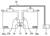
- FIG. 1 and 2 relate to Embodiment 1 of the present invention.
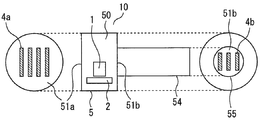
- FIG. 1 is a diagram schematically showing a configuration of a refrigerant detection device
- FIG. 2 is a diagram schematically showing an installation example of the refrigerant detection device. is there.
- the refrigerant detection device 10 As shown in FIG. 1, the refrigerant detection device 10 according to Embodiment 1 of the present invention includes a sensor 1, a leakage determination unit 2, and a casing 5.
- the center of this FIG. 1 is a front view of the refrigerant
- coolant detection apparatus 10 shown through the inside. 1 is a side view of one end side of the refrigerant detection device 10. 1 is a side view on the other end side of the refrigerant detection device 10.
- Sensor 1 can detect the refrigerant.
- a contact combustion type, a semiconductor type, a heat conduction type, a low potential electrolysis type, and an infrared type sensor can be employed.
- an oxygen sensor can be used for the sensor 1.
- the oxygen sensor is a sensor that detects the oxygen concentration in the air.
- a galvanic cell type sensor, a polaro type sensor, a zirconia type sensor, or the like can be used as the oxygen sensor used for the sensor 1, for example, a galvanic cell type sensor, a polaro type sensor, a zirconia type sensor, or the like can be used.
- the refrigerant concentration can be detected as follows. That is, first, the oxygen concentration is obtained based on the output from the oxygen sensor. Next, the concentration of the inflowing gas is obtained assuming that the decrease in oxygen concentration is due to the inflowing gas. And since this inflow gas is a refrigerant
- Sensor 1 outputs a detection signal according to the detected refrigerant concentration. Based on the detection signal output from the sensor 1, the leakage determination unit 2 determines whether or not refrigerant leakage has occurred in the internal space of the chamber that is detected by the refrigerant detection device 10. Specifically, when the sensor 1 detects a refrigerant concentration equal to or higher than a preset reference concentration, the leakage determination unit 2 determines that the refrigerant leakage is detected by the sensor 1. Note that detection of a refrigerant concentration equal to or higher than the reference concentration by the sensor 1 is also referred to as “the sensor 1 has detected refrigerant leakage”.
- the casing 5 is an exterior of the refrigerant detection device 10.
- the casing 5 has, for example, a hollow bottomed cylindrical shape.
- the sensor 1 is accommodated in the casing 5. That is, the sensor 1 is arranged in the sensor arrangement unit 50 inside the casing 5. Further, here, the leakage determination unit 2 is also accommodated in the sensor arrangement unit 50 inside the casing 5.
- the two cylindrical bottom surfaces of the casing 5 are opening formation surfaces. That is, one cylindrical bottom surface of the casing 5 is the first opening forming surface 51a. Further, the other cylindrical bottom surface of the casing 5 is a second opening forming surface 51b.
- the first opening forming surface 51a and the second opening forming surface 51b are both flat here. In the first embodiment, the first opening forming surface 51a and the second opening forming surface 51b are parallel to each other.
- the first opening 4a is formed in the first opening forming surface 51a.
- a second opening 4b is formed in the second opening forming surface 51b.
- the first opening 4a is constituted by, for example, a plurality of slit-shaped openings.
- the 2nd opening 4b is comprised by the some slit-shaped opening, for example.
- the first opening 4 a passes through the inside and the outside of the casing 5. Therefore, the sensor arrangement portion 50 of the casing 5 communicates with the outside of the casing 5 through the first opening 4a.
- the second opening 4b also penetrates the inside and the outside of the casing 5. Therefore, the sensor arrangement portion 50 of the casing 5 communicates with the outside of the casing 5 through the second opening 4b.
- FIG. 2 A plurality of chambers exist in the environment where the refrigerant detection device 10 according to Embodiment 1 of the present invention is installed.
- FIG. 2 an example in which two rooms of a first room 100a and a second room 100b exist as a plurality of rooms is given.
- An air conditioner is installed in the first room 100a and the second room 100b.
- the air conditioner includes an indoor unit, an outdoor unit 21, and a remote controller.
- the indoor unit is installed in a room subject to air conditioning. That is, the first indoor unit 22a is installed in the first room 100a.
- a second indoor unit 22b is installed in the second room 100b.
- the first indoor unit 22a can suck the air in the first room 100a. Then, the first indoor unit 22a can blow out the adjusted air into the first room 100a. Similarly, the second indoor unit 22b can suck in the air in the second room 100b. And the 2nd indoor unit 22b can blow off the air after adjustment to the room
- the outdoor unit 21 is installed outside the first room 100a and the second room 100b.
- the first indoor unit 22a, the second indoor unit 22b, and the outdoor unit 21 are connected by a refrigerant pipe 24.
- a refrigerant is sealed in the refrigerant pipe 24.
- the refrigerant pipe 24 is provided so as to circulate through the first indoor unit 22a, the second indoor unit 22b, and the outdoor unit 21.
- the air conditioner is a so-called multi-model in which a plurality of indoor units (first indoor unit 22a and second indoor unit 22b) are connected to one outdoor unit 21.
- refrigerant with a small global warming potential GWP
- coolant piping 24 is combustible.
- This refrigerant has an average molecular weight larger than that of air (that is, a density higher than that of air), and has a property of sinking downward in the direction of gravity in the air.
- the air conditioner remote control is for the user to operate the air conditioner.
- the first remote controller 23a is installed on the wall surface of the first room 100a.
- the first indoor unit 22a is installed on the ceiling of the first room 100a. Therefore, the first remote controller 23a is arranged vertically below the first indoor unit 22a.
- the first remote controller 23a is electrically connected to the first indoor unit 22a. The user can start and stop the operation of the first indoor unit 22a, change the set temperature, and the like by operating the first remote controller 23a.
- the second remote controller 23b is installed on the wall surface of the second room 100b.
- the second indoor unit 22b is installed on the ceiling of the second room 100b. Therefore, the second remote controller 23b is arranged vertically below the second indoor unit 22b.
- the second remote controller 23b is electrically connected to the second indoor unit 22b. The user can start and stop the operation of the second indoor unit 22b, change the set temperature, and the like by operating the second remote controller 23b.
- the first room 100a and the second room 100b are adjacent to each other, for example.
- the indoor space A of the first room 100a and the indoor space B of the second room 100b are separated by a wall.
- the refrigerant detection device 10 is disposed between the wall surface of the first room 100a and the wall surface of the second room 100b. Note that the wall surface of the first room 100a on the second room 100b side and the wall surface of the second room 100b on the first room 100a side are parallel.
- the first opening forming surface 51a of the refrigerant detection device 10 is exposed in the indoor space A of the first room 100a. Therefore, the first opening 4a of the refrigerant detection device 10 communicates with the indoor space A of the first room 100a. Moreover, the 2nd opening formation surface 51b of the refrigerant
- the first opening 4a can communicate with the inside of the first room 100a which is a room.
- the second opening 4b can communicate with the inside of the second room 100b, which is a room.
- the first room 100a and the second room 100b are different rooms. Therefore, the second opening 4b is located inside a room (the second room 100b in the example of FIG. 2) different from the room (the first room 100a in the example of FIG. 2) to which the first opening 4a can communicate. Communication is possible.
- the air in the indoor space A of the first room 100 a can enter the casing 5 through the first opening 4 a and reach the sensor placement unit 50. Further, the air in the indoor space B of the second room 100 b can enter the casing 5 through the second opening 4 b and reach the sensor placement unit 50.
- the leakage determination unit 2 of the refrigerant detection device 10 is electrically connected to each of the first remote controller 23a and the second remote controller 23b.
- the leakage determination unit 2 outputs a leakage detection signal to each of the first remote controller 23a and the second remote controller 23b.
- the first remote controller 23a and the second remote controller 23b When the first remote controller 23a and the second remote controller 23b receive a leakage detection signal from the leakage determination unit 2, the first remote controller 23a and the second remote controller 23b issue a notification to inform the user and the like that refrigerant leakage has been detected. Specifically, this notification is performed, for example, by sounding from a speaker.
- the first remote controller 23a and the second remote controller 23b include a speaker (not shown) for making a sound.
- the sound emitted from the speaker may be, for example, a buzzer sound, a voice message, or a combination thereof.
- the lamp may be turned on simultaneously with the sound from the speaker.
- the first remote controller 23a and the second remote controller 23b also include a lamp (not shown) for emitting light.
- a lamp for emitting light.
- an LED light emitting diode
- the leakage determination unit 2 may be electrically connected to each of the first indoor unit 22a and the second indoor unit 22b. And you may make it perform the alerting
- a circuit shut-off valve such as an electromagnetic valve is provided in the middle of the refrigerant pipe 24, and the first indoor unit 22a and the second indoor unit 22b are configured to receive a leak detection signal from the leak determination unit 2 when receiving a leak detection signal. The shut-off valve may be closed. By doing in this way, the amount of leakage refrigerant can be minimized.
- the installation position of the refrigerant detection device 10 is adjusted so that the first opening 4a is disposed vertically below the first remote controller 23a and the second opening 4b is disposed vertically below the second remote controller 23b. Has been.
- the refrigerant detection device 10 including the sensor 1 is installed at a position below the first room 100a and the second room 100b, for example, a position where the user can easily operate the first remote controller 23a and the first remote controller 23a. By providing further vertically below the remote control 23b of No. 2, the leaked refrigerant can be easily detected by the sensor 1.
- coolant detection apparatus 10 is about 50 cm or less from the floor surface of the 1st room 100a and the 2nd room 100b.
- the refrigerant detection device 10 when the refrigerant detection device 10 having the above-described configuration is installed as described above will be described.
- the refrigerant leaks from the refrigerant pipe 24 due to breakage or corrosion due to vibration or the like
- the leak point of the refrigerant is in the housing of the first indoor unit 22a
- the refrigerant in the refrigerant pipe 24 is Released into the housing of the machine 22a.
- the leaked refrigerant leaks into the indoor space A of the first room 100a through an opening such as a suction port or an outlet of the first indoor unit 22a.
- the first opening 4a of the refrigerant detection device 10 communicates with the indoor space A of the first room 100a.
- the refrigerant that has leaked into the indoor space A of the first room 100a passes through the first opening 4a and enters the casing 5.
- the leaked refrigerant falls down vertically and stays on the floor surface of the first chamber 100a.
- the refrigerant enters the casing 5 through the first opening 4a.
- the refrigerant that has entered the casing 5 from the first opening 4a reaches the sensor placement section 50 and contacts the sensor 1. And if the refrigerant
- the refrigerant in the refrigerant pipe 24 is released into the casing of the second indoor unit 22b. Then, the leaked refrigerant leaks into the indoor space B of the second room 100b through an opening such as a suction port or an outlet of the second indoor unit 22b.
- the second opening 4b of the refrigerant detection device 10 communicates with the indoor space B of the second room 100b.
- the refrigerant that has leaked into the indoor space B of the second room 100 b passes through the second opening 4 b and enters the casing 5.
- the leaked refrigerant falls down vertically and stays on the floor surface of the second chamber 100b.
- the refrigerant enters the casing 5 through the second opening 4b.
- the refrigerant that has entered the casing 5 from the second opening 4b reaches the sensor placement unit 50 and contacts the sensor 1. And if the refrigerant
- the refrigerant detection device 10 uses the same sensor 1 for both the refrigerant leaking into the indoor space A of the first room 100a and the refrigerant leaking into the indoor space B of the second room 100b. It can detect and output a leak detection signal. Therefore, the refrigerant detection device 10 according to the first embodiment of the present invention can detect the refrigerant leaking into the different chambers with a smaller number of sensors than the number of detection target chambers. For this reason, even if the number of detection target chambers increases, the number of necessary sensors can be reduced, and the refrigerant detection device 10 targeting a plurality of chambers can be realized at low cost. .
- the first opening forming surface 51a where the first opening 4a is formed and the second opening forming surface 51b where the second opening 4b is formed are both flat as described above. Therefore, when the refrigerant detection device 10 is installed, the casing 5 does not protrude from the wall surface, and does not get in the way or impair the aesthetic appearance.
- the place where the leakage determination unit 2 is accommodated is not limited to the casing 5 of the refrigerant detection device 10.
- the leakage determination unit 2 may be provided in the first remote controller 23a and the second remote controller 23b.
- the leakage determination unit 2 may be provided in the first indoor unit 22a and the second indoor unit 22b.
- FIG. FIG. 3 relates to Embodiment 2 of the present invention and is a diagram schematically showing the configuration of the refrigerant detection device.
- the relative position and orientation of the first opening forming surface and the second opening forming surface on the casing of the refrigerant detection device in addition to the configuration of the first embodiment described above, the relative position and orientation of the first opening forming surface and the second opening forming surface on the casing of the refrigerant detection device.
- the variable part which can change one or both of them is provided.
- the refrigerant detection device according to the second embodiment will be described with reference to the case of the configuration of the first embodiment as an example, focusing on differences from the first embodiment.
- the casing 5 of the refrigerant detection device 10 according to Embodiment 2 of the present invention is provided with a first variable portion 52a and a second variable portion 52b as shown in FIG.
- the first variable portion 52a is provided between the sensor placement portion 50 and the first opening forming surface 51a in the casing 5.
- the second variable portion 52b is provided between the sensor placement portion 50 and the second opening forming surface 51b in the casing 5.
- the first variable portion 52a and the second variable portion 52b are formed of at least one of a structure and a material that can be freely bent.
- An example of a structure that can be bent freely includes bellows.
- Examples of the material that can be freely bent include soft vinyl resin, silicon resin, and the like.
- FIG. 3 shows an example in which the first variable portion 52a and the second variable portion 52b are configured as bellows.
- the one or both of the position and orientation of the first opening forming surface 51a with respect to the sensor placement portion 50 can be changed by bending the first variable portion 52a and deforming the outer shape of the casing 5.
- the second variable portion 52b and deforming the outer shape of the casing 5 one or both of the position and orientation of the second opening forming surface 51b with respect to the sensor placement portion 50 can be changed.
- first variable portion 52a and the second variable portion 52b can be changed by the first variable portion 52a and the second variable portion 52b.
- Other configurations are the same as those in the first embodiment, and a description thereof is omitted here.
- the first opening is formed by the first variable portion 52a and the second variable portion 52b according to the orientation of the respective wall surfaces of the first chamber 100a and the second chamber 100b in which the refrigerant detection device 10 is installed.
- the relative orientation of the surface 51a and the second opening forming surface 51b can be changed. Therefore, even if the wall surface of the first room 100a and the wall surface of the second room 100b are not parallel, the first opening forming surface 51a is disposed in parallel with the wall surface of the first room 100a, and It is possible to arrange the second opening forming surface 51b in parallel with the wall surface of the second chamber 100b.
- the position of the first opening 4a in the first room 100a and the position of the second opening 4b in the second room 100b can be freely set within a certain range. Further, the distance between the first opening forming surface 51a and the second opening forming surface 51b may be changed according to the distance between the wall surface of the first room 100a and the wall surface of the second room 100b. it can. Thus, it is possible to flexibly and appropriately cope with various positional relationships of the plurality of chambers in which the refrigerant detection device 10 is to be installed by deforming the casing 5.
- the first opening 4a can be arranged on the floor surface instead of the wall surface of the first room 100a.
- the second opening 4b can be arranged not on the wall surface of the second room 100b but on the floor surface.
- the refrigerant heavier than air stays on the floor surface of the first room 100a or the second room 100b. Therefore, by disposing the first opening 4a and the second opening 4b on the floor surface, it is possible to detect refrigerant leakage in a shorter time.
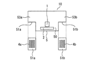
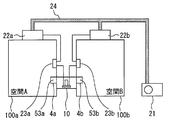
- FIG. FIGS. 4 to 6 relate to Embodiment 3 of the present invention
- FIG. 4 is a diagram schematically illustrating the configuration of the refrigerant detection device
- FIG. 5 is a diagram schematically illustrating an installation example of the refrigerant detection device
- FIG. 6 is a diagram schematically illustrating another example of the configuration of the refrigerant detection device.
- each of the first opening formation surface and the second opening formation surface of the casing is a surface facing downward. It is a thing.
- the refrigerant detection apparatus according to the third embodiment will be described focusing on differences from the first embodiment, taking as an example a case based on the configuration of the first embodiment.
- a first protrusion 53 a is formed on one end side of the casing 5. Further, a second protrusion 53 b is formed on the other end side of the casing 5. The vertical width of the first protrusion 53 a and the second protrusion 53 b is smaller than the vertical width of the sensor placement portion 50 at the center of the casing 5.
- the lower surface of the first protrusion 53a is a first opening forming surface 51a.
- the lower surface of the second protrusion 53b is the second opening forming surface 51b. Accordingly, the first opening forming surface 51a and the second opening forming surface 51b face vertically downward.
- the first opening forming surface 51a and the second opening forming surface 51b are flat surfaces.
- the first opening 4a formed in the first opening formation surface 51a is vertically downward.
- the second opening 4b formed in the second opening forming surface 51b is also vertically downward.
- the refrigerant detection device 10 configured as described above is installed in a state where the first projecting portion 53a of the casing 5 projects inward of the indoor space A from the wall surface of the first room 100a. In this state, the first opening 4a communicates with the indoor space A of the first room 100a downward.
- coolant detection apparatus 10 is installed in the state which the 2nd protrusion part 53b of the casing 5 protruded inside the indoor space B from the wall surface of the 2nd room 100b. In this state, the second opening 4b communicates with the indoor space B of the second room 100b downward.
- Other configurations are the same as those in the first or second embodiment, and the description thereof is omitted here.
- the leaked refrigerant stays on the floor surface of the first room 100a or the second room 100b. If the leakage of the refrigerant continues, the position of the upper end of the area where the refrigerant has accumulated rises. And when the position of the upper end of the area
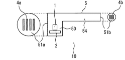
- FIG. FIGS. 7 to 10 relate to Embodiment 4 of the present invention
- FIG. 7 schematically shows the configuration of the refrigerant detection device
- FIG. 8 schematically shows an installation example of the refrigerant detection device
- FIG. 9 is a diagram schematically illustrating another example of the configuration of the refrigerant detection device
- FIG. 10 is a diagram schematically illustrating another installation example of the refrigerant detection device.
- the sensor arrangement portion of the casing is arranged inside the chamber in which the first opening can communicate,
- the two openings can be arranged inside a communicable chamber.
- the refrigerant detection apparatus according to the fourth embodiment will be described by focusing on the differences from the first embodiment, taking as an example the case based on the configuration of the first embodiment.
- a sensor arrangement portion 50 is formed on one end side of the casing 5.
- An extension 54 is formed on the other end side of the casing 5.
- the extension portion 54 is provided so as to extend narrowly from the sensor placement portion 50 to the other end side. That is, the extension portion 54 is thinner than the sensor placement portion 50.
- the side surface of the casing 5 on the sensor arrangement portion 50 side is a first opening forming surface 51a.
- the distal end surface of the extension portion 54 that is, the side surface of the extension portion 54 opposite to the sensor placement portion 50 is a second opening forming surface 51b.
- a first opening 4a is formed in the first opening forming surface 51a.
- a second opening 4b is formed in the second opening forming surface 51b.
- the internal space of the sensor placement portion 50 communicates with the second opening 4b through the internal space of the extension portion 54.
- the sensor arrangement unit 50 of the casing 5 is arranged in either the indoor space A of the first room 100a or the indoor space B of the second room 100b.
- FIG. 8 the example which has arrange
- the extension 54 of the casing 5 extends from the first room 100a side where the sensor placement unit 50 is arranged on the wall between the first room 100a and the second room 100b to the second room 100b side. And passed.
- the second opening forming surface 51b formed at the tip of the extension portion 54 is exposed in the indoor space B of the second room 100b. Therefore, the second opening 4b of the refrigerant detection device 10 communicates with the indoor space B of the second room 100b.
- the first opening forming surface 51a is exposed in the indoor space A of the first room 100a. Therefore, the first opening 4a of the refrigerant detection device 10 communicates with the indoor space A of the first room 100a.
- the air in the indoor space A of the first room 100 a can enter the casing 5 through the first opening 4 a and reach the sensor placement unit 50. Further, the air in the indoor space B of the second room 100 b can enter the casing 5 through the second opening 4 b, reach the sensor placement unit 50 through the extension 54.
- Other configurations are the same as those in any of the first to third embodiments, and the description thereof is omitted here.
- the same effects as in any of the first to third embodiments can be achieved.
- positioning part 50 can be arrange
- the second opening forming surface 51b and the wall surface of the second chamber 100b can be combined. It is possible to make it flush, and in particular, the aesthetic appearance in the second room 100b is not impaired.
- the second opening forming surface 51b is provided at the tip of the extension portion 54 is shown.
- the position of the second opening formation surface 51b is not limited to this, and the second opening formation surface 51b may be provided in the middle of the extension portion 54, for example.
- a sensor arrangement portion 50 is formed on one end side of the casing 5.
- a side surface of one end of the sensor placement unit 50 is a first opening forming surface 51a.
- the side surface at the other end of the sensor placement portion 50 is a second opening forming surface 51b.
- the second opening forming surface 51b is formed with an extension portion 54 that protrudes on the opposite side to the first opening forming surface 51a.
- the extension portion 54 has a hollow cylindrical shape, for example.
- the extension portion 54 is thinner than the sensor placement portion 50.
- One end of the extension portion 54 is connected to the second opening forming surface 51b.
- the other end, that is, the tip of the extension 54 is open.
- the other end (tip) of the extension portion 54 is also referred to as an “open end”.
- the first opening 4a is formed in the first opening forming surface 51a.
- a second opening 4b is formed in the second opening forming surface 51b.
- the 2nd opening 4b is arrange
- the internal space of the sensor placement part 50 leads to the open end of the extension part 54 through the second opening 4 b and the internal space of the extension part 54.
- the sensor arrangement unit 50 of the casing 5 is arranged in either the indoor space A of the first room 100a or the indoor space B of the second room 100b.
- FIG. 10 the example which has arrange
- the extension 54 of the casing 5 extends from the first room 100a side where the sensor placement unit 50 is arranged on the wall between the first room 100a and the second room 100b to the second room 100b side. And passed.
- the open end of the extension portion 54 is exposed in the indoor space B of the second room 100b. Therefore, the second opening 4b of the refrigerant detection device 10 communicates with the indoor space B of the second room 100b via the extension portion 54.
- the first opening forming surface 51a is exposed in the indoor space A of the first room 100a. Therefore, the first opening 4a of the refrigerant detection device 10 communicates with the indoor space A of the first room 100a.
- the air in the indoor space A of the first room 100 a can enter the casing 5 through the first opening 4 a and reach the sensor placement unit 50. Further, the air in the indoor space B of the second room 100b can reach the second opening 4b through the extension 54. The air in the indoor space B of the second room 100 b can enter the casing 5 through the second opening 4 b and reach the sensor placement unit 50.
- the same effect as the effect of the fourth embodiment described above can be obtained.
- a filter that removes foreign matters such as dust from the passing air may be provided at the distal end of the extension portion 54. In this way, it is possible to prevent foreign matters such as dust from entering the extension portion 54. Therefore, it can be suppressed that foreign matters such as dust adhere to the sensor 1 and cause malfunction of the sensor 1.
- any of the plurality of rooms in which the refrigerant detection device 10 is installed may be referred to as the first room 100a or the second room 100b.
- any of the plurality of openings of the casing 5 may be referred to as the first opening 4a or the second opening 4b.
- the number of chambers to be detected by the refrigerant detection device 10 is not limited to two.
- the refrigerant detection device 10 may detect a refrigerant leaking into three or more chambers.
- the casing 5 of the refrigerant detection device 10 has at least as many openings as the number of chambers to be detected. Each of these openings is provided so as to communicate with different chambers.
- the present invention can be used for a refrigerant detection device that detects a refrigerant leaking into a plurality of chambers.
- the present invention is used with a refrigeration cycle apparatus having a housing for accommodating a refrigerant pipe filled with a refrigerant, specifically, for example, an air conditioner such as a floor-mounted type, a ceiling-mounted type, and a wall-mounted type. It can utilize for a refrigerant
Landscapes
- Engineering & Computer Science (AREA)
- Chemical & Material Sciences (AREA)
- Combustion & Propulsion (AREA)
- Mechanical Engineering (AREA)
- General Engineering & Computer Science (AREA)
- Health & Medical Sciences (AREA)
- Life Sciences & Earth Sciences (AREA)
- Physics & Mathematics (AREA)
- Medicinal Chemistry (AREA)
- Food Science & Technology (AREA)
- Analytical Chemistry (AREA)
- Biochemistry (AREA)
- General Health & Medical Sciences (AREA)
- General Physics & Mathematics (AREA)
- Immunology (AREA)
- Pathology (AREA)
- Thermal Sciences (AREA)
- Air Conditioning Control Device (AREA)
Abstract
Description
図1及び図2は、この発明の実施の形態1に係るもので、図1は冷媒検知装置の構成を模式的に示す図、図2は冷媒検知装置の設置例を模式的に示す図である。
図3は、この発明の実施の形態2に係るもので、冷媒検知装置の構成を模式的に示す図である。
なお、他の構成については実施の形態1と同様であり、ここでは、その説明を省略する。
図4から図6は、この発明の実施の形態3に係るもので、図4は冷媒検知装置の構成を模式的に示す図、図5は冷媒検知装置の設置例を模式的に示す図、図6は冷媒検知装置の構成の別例を模式的に示す図である。
なお、他の構成については実施の形態1又は実施の形態2と同様であり、ここでは、その説明を省略する。
図7から図10は、この発明の実施の形態4に係るもので、図7は冷媒検知装置の構成を模式的に示す図、図8は冷媒検知装置の設置例を模式的に示す図、図9は冷媒検知装置の構成の別例を模式的に示す図、図10は冷媒検知装置の別の設置例を模式的に示す図である。
なお、他の構成については実施の形態1から実施の形態3のいずれかと同様であり、ここでは、その説明を省略する。
2 漏洩判定部
4a 第1の開口
4b 第2の開口
5 ケーシング
10 冷媒検知装置
21 室外機
22a 第1の室内機
22b 第2の室内機
23a 第1のリモコン
23b 第2のリモコン
24 冷媒配管
50 センサ配置部
51a 第1の開口形成面
51b 第2の開口形成面
52a 第1の可変部
52b 第2の可変部
53a 第1の突出部
53b 第2の突出部
54 延長部
100a 第1の部屋
100b 第2の部屋
Claims (5)
- 空気調和装置の冷媒配管内に封入される冷媒を検知可能なセンサと、
前記センサが内部に収容されたケーシングと、を備え、
前記ケーシングには、
室の内部に連通可能な第1の開口と、
前記第1の開口が連通可能な前記室とは異なる室の内部に連通可能な第2の開口と、が形成された冷媒検知装置。 - 前記ケーシングは、前記第1の開口が形成される第1の開口形成面と前記第2の開口が形成される第2の開口形成面との相対的な位置及び向きの一方又は両方を変更可能な可変部を備えた請求項1に記載の冷媒検知装置。
- 前記第1の開口が形成される第1の開口形成面及び前記第2の開口が形成される第2の開口形成面は、下方を向いている請求項1に記載の冷媒検知装置。
- 前記ケーシングは、前記センサが内部に配置されるセンサ配置部を備え、
前記センサ配置部は、前記第1の開口形成面及び前記第2の開口形成面よりも上方に配置される請求項3に記載の冷媒検知装置。 - 前記ケーシングは、前記センサが内部に配置されるセンサ配置部を備え、
前記センサ配置部は、前記第1の開口が連通可能な前記室の内部に配置可能である請求項1から請求項3のいずれか一項に記載の冷媒検知装置。
Priority Applications (5)
| Application Number | Priority Date | Filing Date | Title |
|---|---|---|---|
| PCT/JP2017/009755 WO2018163417A1 (ja) | 2017-03-10 | 2017-03-10 | 冷媒検知装置 |
| CN201780085463.4A CN110382966B (zh) | 2017-03-10 | 2017-03-10 | 制冷剂检测装置 |
| US16/468,316 US11460206B2 (en) | 2017-03-10 | 2017-03-10 | Refrigerant detection apparatus |
| JP2019504278A JP7010280B2 (ja) | 2017-03-10 | 2017-03-10 | 冷媒検知装置 |
| EP17900267.0A EP3594579A4 (en) | 2017-03-10 | 2017-03-10 | REFRIGERANT DETECTION DEVICE |
Applications Claiming Priority (1)
| Application Number | Priority Date | Filing Date | Title |
|---|---|---|---|
| PCT/JP2017/009755 WO2018163417A1 (ja) | 2017-03-10 | 2017-03-10 | 冷媒検知装置 |
Publications (1)
| Publication Number | Publication Date |
|---|---|
| WO2018163417A1 true WO2018163417A1 (ja) | 2018-09-13 |
Family
ID=63448172
Family Applications (1)
| Application Number | Title | Priority Date | Filing Date |
|---|---|---|---|
| PCT/JP2017/009755 Ceased WO2018163417A1 (ja) | 2017-03-10 | 2017-03-10 | 冷媒検知装置 |
Country Status (5)
| Country | Link |
|---|---|
| US (1) | US11460206B2 (ja) |
| EP (1) | EP3594579A4 (ja) |
| JP (1) | JP7010280B2 (ja) |
| CN (1) | CN110382966B (ja) |
| WO (1) | WO2018163417A1 (ja) |
Cited By (6)
| Publication number | Priority date | Publication date | Assignee | Title |
|---|---|---|---|---|
| JP2022125771A (ja) * | 2021-02-17 | 2022-08-29 | パナソニックIpマネジメント株式会社 | 室内機 |
| JP2022129916A (ja) * | 2021-02-25 | 2022-09-06 | パナソニックIpマネジメント株式会社 | 冷媒センサユニット |
| JP2022149443A (ja) * | 2021-03-25 | 2022-10-06 | 三菱電機株式会社 | 冷凍サイクル装置 |
| JP7682417B1 (ja) * | 2024-06-04 | 2025-05-23 | 三菱電機株式会社 | 室内機、および空気調和機 |
| JP2025112443A (ja) * | 2024-01-19 | 2025-08-01 | 株式会社富士通ゼネラル | 冷媒検知装置 |
| JP7907622B2 (ja) | 2024-01-19 | 2026-08-19 | 株式会社ゼネラル | 冷媒検知装置 |
Families Citing this family (2)
| Publication number | Priority date | Publication date | Assignee | Title |
|---|---|---|---|---|
| US11326797B2 (en) * | 2020-04-14 | 2022-05-10 | Haier Us Appliance Solutions, Inc. | Gas sensing system for an air conditioner unit |
| CN119022410B (zh) * | 2024-08-30 | 2025-11-21 | Tcl空调器(中山)有限公司 | 空调系统和控制方法 |
Citations (3)
| Publication number | Priority date | Publication date | Assignee | Title |
|---|---|---|---|---|
| JP2011202831A (ja) * | 2010-03-25 | 2011-10-13 | Hitachi Appliances Inc | リモートコントローラ及び室内ユニット並びに空気調和機 |
| JP2012013348A (ja) | 2010-07-02 | 2012-01-19 | Panasonic Corp | 空気調和機 |
| JP2012013339A (ja) * | 2010-07-02 | 2012-01-19 | Hitachi Appliances Inc | 空気調和機 |
Family Cites Families (22)
| Publication number | Priority date | Publication date | Assignee | Title |
|---|---|---|---|---|
| US4167858A (en) * | 1976-10-27 | 1979-09-18 | Nippondenso Co., Ltd. | Refrigerant deficiency detecting apparatus |
| JPH01318730A (ja) * | 1988-06-21 | 1989-12-25 | Japan Electron Control Syst Co Ltd | 排気ガスの気筒別酸素濃度検出装置 |
| JPH0322818A (ja) * | 1989-06-19 | 1991-01-31 | Hitachi Ltd | 出力電圧異常検出回路 |
| JPH0327576U (ja) * | 1989-07-25 | 1991-03-19 | ||
| JP2005016822A (ja) | 2003-06-25 | 2005-01-20 | Toshiba Kyaria Kk | 可燃性冷媒空気調和機の冷媒漏洩検知装置 |
| JP5401825B2 (ja) * | 2008-04-16 | 2014-01-29 | パナソニック株式会社 | 自動販売機 |
| JP5481821B2 (ja) * | 2008-10-06 | 2014-04-23 | パナソニック株式会社 | 自動販売機 |
| CN101839793A (zh) * | 2009-03-22 | 2010-09-22 | 鹤壁市众邦一明家电有限公司 | 一种高精度汽车空调检漏仪 |
| KR20110008888U (ko) * | 2010-03-12 | 2011-09-20 | 박장로 | 에어컨 배관 점검구 |
| US20140196483A1 (en) * | 2011-09-13 | 2014-07-17 | Mitsubishi Electric Corporation | Heat pump apparatus and method of controlling heat pump apparatus |
| JP5931688B2 (ja) | 2012-10-17 | 2016-06-08 | ジョンソンコントロールズ ヒタチ エア コンディショニング テクノロジー(ホンコン)リミテッド | 空気調和機 |
| KR101571111B1 (ko) * | 2013-05-09 | 2015-11-23 | 심기섭 | 온도와 기압의 평형을 이용한 환기 유닛 및 이를 이용한 저장 시스템 |
| US20150028209A1 (en) * | 2013-07-26 | 2015-01-29 | Rey P. Harju | Refrigerant Gas Leak Detector |
| CN104566677B (zh) * | 2013-10-25 | 2018-08-17 | 广东美的制冷设备有限公司 | 空调器 |
| JP6375639B2 (ja) * | 2014-02-21 | 2018-08-22 | ダイキン工業株式会社 | 空気調和装置 |
| CN104166352A (zh) * | 2014-08-04 | 2014-11-26 | 珠海格力电器股份有限公司 | 气体泄漏检测仪及气体泄漏检测控制方法 |
| CN204534983U (zh) * | 2015-03-17 | 2015-08-05 | 四川省科本哈根能源科技有限公司 | 一种用于中央空调的安防系统 |
| CN104833053B (zh) * | 2015-04-30 | 2017-12-05 | 广东美的制冷设备有限公司 | 空调器的安全防护方法及系统 |
| JP6380500B2 (ja) * | 2016-10-17 | 2018-08-29 | ダイキン工業株式会社 | 冷凍装置 |
| JP6380696B2 (ja) * | 2017-02-14 | 2018-08-29 | ダイキン工業株式会社 | 冷凍装置 |
| EP3607250B1 (en) * | 2017-04-06 | 2024-03-27 | Carrier Corporation | Moderate-to-low global warming potential value refrigerant leak detection |
| US11604156B2 (en) * | 2017-05-12 | 2023-03-14 | Carrier Corporation | Method and system for multi-sensor gas detection |
-
2017
- 2017-03-10 JP JP2019504278A patent/JP7010280B2/ja not_active Expired - Fee Related
- 2017-03-10 WO PCT/JP2017/009755 patent/WO2018163417A1/ja not_active Ceased
- 2017-03-10 US US16/468,316 patent/US11460206B2/en active Active
- 2017-03-10 CN CN201780085463.4A patent/CN110382966B/zh not_active Expired - Fee Related
- 2017-03-10 EP EP17900267.0A patent/EP3594579A4/en not_active Withdrawn
Patent Citations (3)
| Publication number | Priority date | Publication date | Assignee | Title |
|---|---|---|---|---|
| JP2011202831A (ja) * | 2010-03-25 | 2011-10-13 | Hitachi Appliances Inc | リモートコントローラ及び室内ユニット並びに空気調和機 |
| JP2012013348A (ja) | 2010-07-02 | 2012-01-19 | Panasonic Corp | 空気調和機 |
| JP2012013339A (ja) * | 2010-07-02 | 2012-01-19 | Hitachi Appliances Inc | 空気調和機 |
Non-Patent Citations (1)
| Title |
|---|
| See also references of EP3594579A4 |
Cited By (14)
| Publication number | Priority date | Publication date | Assignee | Title |
|---|---|---|---|---|
| JP7535702B2 (ja) | 2021-02-17 | 2024-08-19 | パナソニックIpマネジメント株式会社 | 室内機 |
| JP2022125771A (ja) * | 2021-02-17 | 2022-08-29 | パナソニックIpマネジメント株式会社 | 室内機 |
| JP2024166394A (ja) * | 2021-02-25 | 2024-11-28 | パナソニックIpマネジメント株式会社 | 冷媒センサユニット |
| JP7565541B2 (ja) | 2021-02-25 | 2024-10-11 | パナソニックIpマネジメント株式会社 | 冷媒センサユニット |
| JP2024166395A (ja) * | 2021-02-25 | 2024-11-28 | パナソニックIpマネジメント株式会社 | 冷媒センサユニット |
| JP2022129916A (ja) * | 2021-02-25 | 2022-09-06 | パナソニックIpマネジメント株式会社 | 冷媒センサユニット |
| JP7742566B2 (ja) | 2021-02-25 | 2025-09-22 | パナソニックIpマネジメント株式会社 | 冷媒センサユニット |
| JP2025161907A (ja) * | 2021-02-25 | 2025-10-24 | パナソニックIpマネジメント株式会社 | 冷媒センサユニット |
| JP7870500B2 (ja) | 2021-02-25 | 2026-06-05 | パナソニックIpマネジメント株式会社 | 冷媒センサユニット |
| JP2022149443A (ja) * | 2021-03-25 | 2022-10-06 | 三菱電機株式会社 | 冷凍サイクル装置 |
| JP2025112443A (ja) * | 2024-01-19 | 2025-08-01 | 株式会社富士通ゼネラル | 冷媒検知装置 |
| JP7907622B2 (ja) | 2024-01-19 | 2026-08-19 | 株式会社ゼネラル | 冷媒検知装置 |
| JP7682417B1 (ja) * | 2024-06-04 | 2025-05-23 | 三菱電機株式会社 | 室内機、および空気調和機 |
| WO2025253487A1 (ja) * | 2024-06-04 | 2025-12-11 | 三菱電機株式会社 | 室内機、および空気調和機 |
Also Published As
| Publication number | Publication date |
|---|---|
| CN110382966B (zh) | 2021-04-09 |
| EP3594579A1 (en) | 2020-01-15 |
| JP7010280B2 (ja) | 2022-01-26 |
| EP3594579A4 (en) | 2020-02-26 |
| JPWO2018163417A1 (ja) | 2019-12-12 |
| US20190383508A1 (en) | 2019-12-19 |
| CN110382966A (zh) | 2019-10-25 |
| US11460206B2 (en) | 2022-10-04 |
Similar Documents
| Publication | Publication Date | Title |
|---|---|---|
| JP7010280B2 (ja) | 冷媒検知装置 | |
| JP6911441B2 (ja) | 環境監視装置 | |
| JP6065962B1 (ja) | 冷凍サイクル装置 | |
| JP6402779B2 (ja) | 冷媒漏洩検知装置及びこれを備えた冷凍サイクル装置 | |
| JP6958627B2 (ja) | 空気調和機 | |
| JP6176304B2 (ja) | コンセント、そのカバープレート及び冷媒検知装置、並びに、コンセント又は冷媒検知装置を備えた環境監視システム | |
| JP6828401B2 (ja) | 空気調和機 | |
| JP2019011914A (ja) | 空気調和機 | |
| WO2016103785A1 (ja) | 冷媒漏洩検知装置及びこれを備えた冷凍サイクル装置 | |
| JPWO2015194596A1 (ja) | 空気調和装置の室内機、及びその室内機を備えた空気調和装置 | |
| WO2002027245A1 (fr) | Climatiseur | |
| JP2016090175A (ja) | 室内機、および、それを備える空気調和機 | |
| JP2016223640A (ja) | 冷凍空調装置 | |
| JP2022112061A (ja) | 空気調和機 | |
| US20220260259A1 (en) | Air conditioning indoor unit and air conditioner | |
| US20160348927A1 (en) | Air conditioner | |
| JP2020134033A (ja) | 室内ユニット | |
| JPWO2017183104A1 (ja) | 空気調和機 | |
| JP2021076263A (ja) | 空調室内機及び空調室内機を備えた空調機 | |
| JP7067144B2 (ja) | 空気調和装置 | |
| JP7439517B2 (ja) | 送風装置及び送風システム | |
| JP2019184090A (ja) | 空気調和機 | |
| JP6819344B2 (ja) | 環境監視装置 | |
| JPWO2017109932A1 (ja) | 冷却倉庫及び制御装置 | |
| JP5790731B2 (ja) | 空気調和機の室内機 |
Legal Events
| Date | Code | Title | Description |
|---|---|---|---|
| 121 | Ep: the epo has been informed by wipo that ep was designated in this application |
Ref document number: 17900267 Country of ref document: EP Kind code of ref document: A1 |
|
| ENP | Entry into the national phase |
Ref document number: 2019504278 Country of ref document: JP Kind code of ref document: A |
|
| NENP | Non-entry into the national phase |
Ref country code: DE |
|
| WWE | Wipo information: entry into national phase |
Ref document number: 2017900267 Country of ref document: EP |
|
| ENP | Entry into the national phase |
Ref document number: 2017900267 Country of ref document: EP Effective date: 20191010 |
|
| WWW | Wipo information: withdrawn in national office |
Ref document number: 2017900267 Country of ref document: EP |