WO2018163642A1 - ガスケット - Google Patents
ガスケット Download PDFInfo
- Publication number
- WO2018163642A1 WO2018163642A1 PCT/JP2018/002384 JP2018002384W WO2018163642A1 WO 2018163642 A1 WO2018163642 A1 WO 2018163642A1 JP 2018002384 W JP2018002384 W JP 2018002384W WO 2018163642 A1 WO2018163642 A1 WO 2018163642A1
- Authority
- WO
- WIPO (PCT)
- Prior art keywords
- base
- seal
- gasket
- bead
- metal member
- Prior art date
- Legal status (The legal status is an assumption and is not a legal conclusion. Google has not performed a legal analysis and makes no representation as to the accuracy of the status listed.)
- Ceased
Links
Images




Classifications
-
- F—MECHANICAL ENGINEERING; LIGHTING; HEATING; WEAPONS; BLASTING
- F16—ENGINEERING ELEMENTS AND UNITS; GENERAL MEASURES FOR PRODUCING AND MAINTAINING EFFECTIVE FUNCTIONING OF MACHINES OR INSTALLATIONS; THERMAL INSULATION IN GENERAL
- F16J—PISTONS; CYLINDERS; SEALINGS
- F16J15/00—Sealings
- F16J15/02—Sealings between relatively-stationary surfaces
- F16J15/06—Sealings between relatively-stationary surfaces with solid packing compressed between sealing surfaces
- F16J15/08—Sealings between relatively-stationary surfaces with solid packing compressed between sealing surfaces with exclusively metal packing
- F16J15/0806—Sealings between relatively-stationary surfaces with solid packing compressed between sealing surfaces with exclusively metal packing characterised by material or surface treatment
-
- F—MECHANICAL ENGINEERING; LIGHTING; HEATING; WEAPONS; BLASTING
- F16—ENGINEERING ELEMENTS AND UNITS; GENERAL MEASURES FOR PRODUCING AND MAINTAINING EFFECTIVE FUNCTIONING OF MACHINES OR INSTALLATIONS; THERMAL INSULATION IN GENERAL
- F16J—PISTONS; CYLINDERS; SEALINGS
- F16J15/00—Sealings
- F16J15/02—Sealings between relatively-stationary surfaces
- F16J15/06—Sealings between relatively-stationary surfaces with solid packing compressed between sealing surfaces
- F16J15/08—Sealings between relatively-stationary surfaces with solid packing compressed between sealing surfaces with exclusively metal packing
- F16J15/0818—Flat gaskets
- F16J15/0825—Flat gaskets laminated
-
- F—MECHANICAL ENGINEERING; LIGHTING; HEATING; WEAPONS; BLASTING
- F16—ENGINEERING ELEMENTS AND UNITS; GENERAL MEASURES FOR PRODUCING AND MAINTAINING EFFECTIVE FUNCTIONING OF MACHINES OR INSTALLATIONS; THERMAL INSULATION IN GENERAL
- F16J—PISTONS; CYLINDERS; SEALINGS
- F16J15/00—Sealings
- F16J15/02—Sealings between relatively-stationary surfaces
- F16J15/06—Sealings between relatively-stationary surfaces with solid packing compressed between sealing surfaces
- F16J15/08—Sealings between relatively-stationary surfaces with solid packing compressed between sealing surfaces with exclusively metal packing
-
- F—MECHANICAL ENGINEERING; LIGHTING; HEATING; WEAPONS; BLASTING
- F16—ENGINEERING ELEMENTS AND UNITS; GENERAL MEASURES FOR PRODUCING AND MAINTAINING EFFECTIVE FUNCTIONING OF MACHINES OR INSTALLATIONS; THERMAL INSULATION IN GENERAL
- F16J—PISTONS; CYLINDERS; SEALINGS
- F16J15/00—Sealings
- F16J15/02—Sealings between relatively-stationary surfaces
- F16J15/06—Sealings between relatively-stationary surfaces with solid packing compressed between sealing surfaces
- F16J15/08—Sealings between relatively-stationary surfaces with solid packing compressed between sealing surfaces with exclusively metal packing
- F16J15/0818—Flat gaskets
-
- F—MECHANICAL ENGINEERING; LIGHTING; HEATING; WEAPONS; BLASTING
- F16—ENGINEERING ELEMENTS AND UNITS; GENERAL MEASURES FOR PRODUCING AND MAINTAINING EFFECTIVE FUNCTIONING OF MACHINES OR INSTALLATIONS; THERMAL INSULATION IN GENERAL
- F16J—PISTONS; CYLINDERS; SEALINGS
- F16J15/00—Sealings
- F16J15/02—Sealings between relatively-stationary surfaces
- F16J15/06—Sealings between relatively-stationary surfaces with solid packing compressed between sealing surfaces
- F16J15/08—Sealings between relatively-stationary surfaces with solid packing compressed between sealing surfaces with exclusively metal packing
- F16J15/0818—Flat gaskets
- F16J15/0825—Flat gaskets laminated
- F16J15/0831—Flat gaskets laminated with mounting aids
-
- F—MECHANICAL ENGINEERING; LIGHTING; HEATING; WEAPONS; BLASTING
- F16—ENGINEERING ELEMENTS AND UNITS; GENERAL MEASURES FOR PRODUCING AND MAINTAINING EFFECTIVE FUNCTIONING OF MACHINES OR INSTALLATIONS; THERMAL INSULATION IN GENERAL
- F16J—PISTONS; CYLINDERS; SEALINGS
- F16J15/00—Sealings
- F16J15/02—Sealings between relatively-stationary surfaces
- F16J15/06—Sealings between relatively-stationary surfaces with solid packing compressed between sealing surfaces
- F16J15/08—Sealings between relatively-stationary surfaces with solid packing compressed between sealing surfaces with exclusively metal packing
- F16J15/0887—Sealings between relatively-stationary surfaces with solid packing compressed between sealing surfaces with exclusively metal packing the sealing effect being obtained by elastic deformation of the packing
-
- F—MECHANICAL ENGINEERING; LIGHTING; HEATING; WEAPONS; BLASTING
- F16—ENGINEERING ELEMENTS AND UNITS; GENERAL MEASURES FOR PRODUCING AND MAINTAINING EFFECTIVE FUNCTIONING OF MACHINES OR INSTALLATIONS; THERMAL INSULATION IN GENERAL
- F16J—PISTONS; CYLINDERS; SEALINGS
- F16J15/00—Sealings
- F16J15/02—Sealings between relatively-stationary surfaces
- F16J15/06—Sealings between relatively-stationary surfaces with solid packing compressed between sealing surfaces
- F16J15/08—Sealings between relatively-stationary surfaces with solid packing compressed between sealing surfaces with exclusively metal packing
- F16J15/0818—Flat gaskets
- F16J2015/085—Flat gaskets without fold over
-
- F—MECHANICAL ENGINEERING; LIGHTING; HEATING; WEAPONS; BLASTING
- F16—ENGINEERING ELEMENTS AND UNITS; GENERAL MEASURES FOR PRODUCING AND MAINTAINING EFFECTIVE FUNCTIONING OF MACHINES OR INSTALLATIONS; THERMAL INSULATION IN GENERAL
- F16J—PISTONS; CYLINDERS; SEALINGS
- F16J15/00—Sealings
- F16J15/02—Sealings between relatively-stationary surfaces
- F16J15/06—Sealings between relatively-stationary surfaces with solid packing compressed between sealing surfaces
- F16J15/08—Sealings between relatively-stationary surfaces with solid packing compressed between sealing surfaces with exclusively metal packing
- F16J15/0818—Flat gaskets
- F16J2015/0868—Aspects not related to the edges of the gasket
Definitions
- the present invention relates to a gasket.
- the rubber O-ring has a long history.
- O-rings have the advantage of a relatively simple structure, but on the other hand, groove processing is required to fit the O-ring into the member to be sealed, and the number of manufacturing steps is increased by the assembly process into the groove.
- the attached state cannot be confirmed from the outside after the sealing surface is fastened.
- requiring a high level of surface roughness and parallelism of the seal surface is also the fate of a rubber O-ring.
- liquid gaskets have been developed that can seal each other by simply applying to the sealing surfaces. Since the liquid gasket has fluidity before curing, the tolerance for the surface roughness and parallelism of the seal surface is high.
- liquid gaskets are not versatile, and when considering adoption, a degreasing process for the seal surface is required as a pre-process of the application process. In the application process, dedicated equipment for application is required. It must be taken into account that the manufacturing cycle time becomes long because it must be done.
- the inventor of the present application examined the use of a plate-like gasket as a sealing member that can overcome the above-mentioned various problems that are unavoidable for rubber O-rings and liquid gaskets, and worked to improve it.
- the plate-like gasket is widely used as a gasket for sealing between a cylinder block and a cylinder head in an automobile engine, for example.
- this type of gasket is formed by laminating a plurality of flat plate-shaped stainless steel, forming a convex portion called a bead at a position around the combustion chamber by press working, and coating the surface with rubber (for example, (See Non-Patent Document 1, page 92, left column, line 1 to page 93, left column, last line, FIGS. 1 and 2).
- Patent Document 1 discloses a plate-like gasket having a form different from the cylinder head gasket as a gasket for a speed reducer.
- This gasket (seal ring (34)) has a stepped shape on the inner peripheral side and the outer peripheral side, and rubber layers are provided on both surfaces of a metal base.
- the metal base portion is “steel plate portion (41a) (42a) (43a)”
- the rubber layer is “first rubber portion (41b), third rubber portion (42b), fifth rubber portion (43b)”.
- the second rubber part (41c), the fourth rubber part (42c), and the sixth rubber part (43c) "(see paragraphs [0043] to [0045] of Patent Document 1).
- a gasket (seal ring (34)) is used as a part that is interposed and sealed between the first housing (31) and the second housing (33) of the speed reducer.
- the first housing (31) includes an input shaft (11) connected to the steering wheel, and an output shaft (12) connected to the input shaft (11) via a steering angle ratio variable steering device (2). Is housed.
- the second housing (33) is connected to the output shaft (12) via the torsion bar (21), and houses each part such as a pinion gear (22a) connected to the rack shaft.
- Gaskets coated with rubber on both sides of the metal plate as described above have excellent characteristics that the tolerance to the surface roughness and parallelism of the mating machined surface is high because the surface is coated with rubber. is doing.
- the inventor of the invention according to the present application performs an endurance test, and as a result, the initial fastening torque (axial force) decreases at a position near the bolt for fastening the two members to be sealed. It was confirmed that stress relaxation occurred. This phenomenon is presumed to be caused by thinning the rubber in the vicinity of the bolt by tightening the bolt.
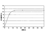
- FIG. 12 is a graph of stress relaxation characteristics showing the results of a durability test performed on a gasket coated with rubber on both surfaces of a metal plate, with the horizontal axis representing time (H) and the vertical axis representing stress relaxation rate (%). ing. As is clear from this graph, the stress relaxation rate rapidly increases with the passage of time, the increase rate starts to decrease after about 8 hours, and becomes almost flat after about 15 hours.
- the present inventor has confirmed that when the gasket is used as a seal member, stress relaxation of about 10 to 30% occurs in the vicinity of the bolt.
- the present invention has an object of suppressing stress relaxation in a gasket in which rubber is coated on both surfaces of a metal plate.
- One aspect of the gasket of the present invention includes a base made of a flat metal member, a flat metal member having a rubber-like elastic material layer laminated on the surface thereof, and a seal base thinner than the base, and the seal.
- a seal portion having a bead formed by a bent shape of a base portion, the base portion and the seal base portion are positioned in the same plane, and the bead is protruded from a plane including at least one surface of the base portion, and the base portion and the seal And a connecting part that connects the parts.
- a base part made of a flat metal member, and a foam rubber made of foam rubber on the surface of a flat metal member whose thickness is thinner than the base part The layers are stacked, and the seal part having a thickness larger than the base part as a whole, the base part and the seal base part are positioned in the same plane, and the foamed rubber layer protrudes from a plane including at least one surface of the base part.
- the compression amount of the bead and the compression amount of the foamed rubber layer can be regulated by the thickness of the base portion, and the stress relaxation generated in the bead portion can be suppressed.
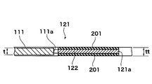
- FIG. 4 is a cross-sectional view taken along line AA in FIG.
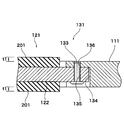
- FIG. 4 is a cross-sectional view taken along line BB in FIG. 3 illustrating an enlarged connection structure between a base portion and a seal portion by the connection portion.
- FIG. 9 is a cross-sectional view taken along line AA in FIG.
- FIG. 9 is a cross-sectional view taken along line BB in FIG. 8 showing an enlarged connection structure between a base portion and a seal portion by the connection portion.
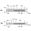
- (A) is a vertical front view of the state which made the upper housing face the lower housing which mounted the gasket
- (B) is a lower housing and an upper housing.
- the present embodiment is an application example to a speed reducer 11 that forms part of a vehicle steering device.
- the speed reducer 11 using the gasket 101 of the present embodiment will be described.
- the housing 12 of the speed reducer 11 is divided into an upper housing 13 and a lower housing 14.
- the upper housing 13 and the lower housing 14 have a cylindrical cup shape, and are provided with joint surfaces 13a and 14a around the opening portion, respectively.
- the upper housing 13 and the lower housing 14 are integrated by joining their joint surfaces 13a and 14a through the gasket 101.
- flanges 13 b and 14 b extending in the circumferential direction from the joint surface 13 a of the upper housing 13 and the joint surface 14 a of the lower housing 14 are provided, and these flanges 13 b and 14 b are bolts 15. And the nut 16.
- bolt holes 17 are provided in the flanges 13 b and 14 b along the axial direction of the speed reducer 11.
- the gasket 101 is also provided with a plurality of through holes 102 in alignment with the bolt holes 17 (see also FIG. 3). Therefore, when the upper housing 13 and the lower housing 14 are joined with the gasket 101 interposed therebetween, the gasket 15 is sandwiched between the upper housing 13 and the lower housing 14 by passing the bolts 15 through the through holes 102. .
- the reducer 11 is interposed between a steering shaft (not shown) of the vehicle and a rack and pinion mechanism (not shown) that changes the angle of the front wheels of the vehicle, and varies the steering angle ratio of the steering shaft.
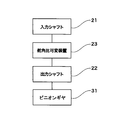
- the speed reducer 11 includes an input-side input shaft 21 and an output shaft 22 that are rotatably attached to the upper housing 13, and an output-side pinion gear 31 that is rotatably attached to the lower housing 14.
- the input shaft 21 is connected to the steering shaft, and the pinion gear 31 is a part of the rack and pinion mechanism.
- a steering angle ratio variable device 23 is provided between the input shaft 21 and the output shaft 22.
- the steering angle ratio variable device 23 is a device for changing the rotation angle input to the input shaft 21 by steering the steering shaft and transmitting the rotation with the variable angle to the output shaft 22.
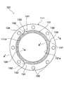
- the gasket 101 has a structure in which a base portion 111 and a seal portion 121 are connected by a connecting portion 131.
- the base portion 111 and the seal portion 121 are formed in an endless shape having openings 111a and 121a at the center portions, more specifically in an annular shape.
- These base portion 111 and seal portion 121 are concentrically positioned and are connected to connecting portion 131 in a state where seal portion 121 is disposed on the inner peripheral side of base portion 111.
- three connecting pieces 132 that protrude from the outer peripheral surface of the seal portion 121 at intervals of 120 degrees are fixed to the base portion 111 by pins 133.
- the base 111 is formed of a flat metal member.
- the base 111 is provided with the through hole 102 of the gasket 101 described above. These through holes 102 are arranged at equal intervals along a circumference that is a concentric circle of the base 111. Since the base 111 is a metal member, it does not assume elastic deformation, and defines a facing distance between the upper housing 13 and the lower housing 14 that are joined to each other (see FIGS. 6B and 7).
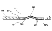
- the seal portion 121 uses a seal base portion 124 in which a rubber-like elastic material layer 123 is coated on the surface of a base material 122 that is a flat metal member as a base.
- the seal base 124 is thinner than the base 111, and is set to a thickness that is about half that of the base 111, for example.
- the seal base 124 has a bent shape along a concentric circle, and this bent shape is a bead 125.
- the height h of the bead 125 is formed to be larger than the thickness t of the base 111 (see FIG. 4).
- the base material 122 of the seal base 124 is made of, for example, stainless steel, cold rolled steel plate, galvanized steel plate, or aluminum plywood.
- the rubber used as the material of the rubber-like elastic material layer 123 includes at least one of nitrile rubber, styrene butadiene rubber, fluorine rubber, acrylic rubber, and silicon rubber, for example, as a blend.
- the connecting portion 131 fixes the three connecting pieces 132 protruding from the outer periphery of the seal portion 121 to the back side of the base portion 111.
- recesses 134 are formed at intervals of 120 degrees on the inner periphery that defines the opening 111 a, and the connecting pieces 132 are fitted into these recesses 134.
- the recesses 134 are formed in the same shape as the connecting pieces 132 that fit together, and are offset from one surface of the base 111, that is, from the back surface, in the same shape as the thickness of the connecting pieces 132.
- an attachment hole 135 is formed in the connecting piece 132, and a pin hole 136 penetrating from the inside of the recess 134 to the surface is formed in the base 111. Is formed. Therefore, the connecting piece 132 is fixed to the base 111 by press-fitting the pin 133 penetrating the mounting hole 135 into the pin hole 136.
- the seal base 124 has one surface on which the bead 125 does not protrude positioned within the same surface as the back surface of the base 111.
- the bead 125 is (h ⁇ t) from the surface side, which is the other surface of the base 111. ) Protrudes by the dimension of).
- the thickness of the base portion 111 is defined to be about 50 to 60% of the height h of the bead 125, that is, the height of the seal portion 121.
- the speed reducer 11 is required to be airtight between the upper housing 13 and the lower housing 14.
- the gasket 101 is sandwiched between the joint surfaces 13a and 14a so as to ensure airtightness.
- the gasket 101 is placed on the joining surface 14 a of the lower housing 14 as shown in FIG.
- the position of the through hole 102 of the gasket 101 is aligned with the bolt hole 17 provided in the flange 14 b of the lower housing 14.
- the positions of the bolt holes 17 are aligned, the upper housing 13 is placed on the lower housing 14, and the flanges 13 b and 14 b are tightened by the bolts 15 and the nuts 16.
- the bead 125 is compressed, and the gasket 101 is sandwiched between the upper housing 13 and the lower housing 14 in the form of the thickness t of the base 111.
- the bead 125 is deformed into a shape in which the top is pressed against the joint surface of the upper housing 13 and is crushed, and the base portion placed on the joint surface 14a of the lower housing 14 is widened.
- the seal portion 121 seems to have lifted the edge portions of the inner peripheral side and the outer peripheral side because the metal base material 122 having high hardness maintains the bent shape. It transforms into a simple shape.
- the connecting piece 132 fixed to the base 111 does not change its position, but is deformed in the region between the connecting piece 132 and the connecting piece 132, and is deformed into a raised shape. To do.
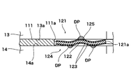
- the bead 125 abuts against the joint surfaces 13a and 14a of the upper housing 13 and the lower housing 14 at three locations, two locations on the lower surface and one location on the upper surface, as shown schematically in FIG.
- the pressure distribution DP is shown. Therefore, the joint surfaces 13a and 14a between the upper housing 13 and the lower housing 14 are sealed in three regions of the bead 125 showing the surface pressure distribution DP.
- the base 111 of the gasket 101 since the base 111 of the gasket 101 is a metal member, it does not assume elastic deformation. For this reason, the upper housing 13 and the lower housing 14 that are fastened face each other with the thickness t of the base 111 opened. At this time, as described above, the seal portion 121 of the gasket 101 is set to about half the thickness of the base portion 111, so that the bead 125 is not completely crushed and has a bendable margin. For this reason, compared with the case where it is completely crushed, the plastic deformation is less likely to occur in the bead 125.
- the gasket 101 of the present embodiment stress relaxation generated in the bead 125 can be suppressed.
- the base 111 of the gasket 101 defines a facing distance between the upper housing 13 and the lower housing 14 that are joined to each other (see FIGS. 6B and 7). For this reason, according to the gasket 101 of this Embodiment, the compression amount of the bead 125 can be controlled by the thickness of the base 111.
- the gasket 101 of the present embodiment manages the amount of compression of the bead 125 by the base 111 made of a flat metal member, for example, a steel plate, so that the bead 125 is not fully compressed.
- the restoring characteristics of the beads 125 are improved, and the restoring properties of the beads 125 are maintained even after being compressed by using the gasket 101.
- the joint surface 13a of the upper housing 13 and the joint surface 14a of the lower housing 14 are joined via the gasket 101, and the flanges 13b and 14b are fastened by the bolt 15 and the nut 16 to thereby apply pressure to the bead 125.
- the tolerance of the bead 125 until the opening of the housing 12 is caused by the loss of the restoring property, that is, the margin for the bead 125 to stop functioning increases.
- the stress relaxation generated by the rapid decrease of the fastening torque (axial force) with the passage of time is suppressed, and the rapid increase of the stress relaxation rate is prevented. be able to.
- connecting portion 131 positions seal base 124 in the same plane as one surface (back surface) of base 111, and includes the other surface (front surface) of base 111 at seal portion 121.
- a bead 125 is projected from the plane. Accordingly, the amount of protrusion of the bead 125 from the base 111 can be set as the amount of compression of the bead 125, so that the calculation of the surface pressure distribution DP (see FIG. 7) can be facilitated, and the design of each part can be facilitated. .
- the base 111 and the seal 121 are formed in an endless shape (annular shape) having an opening 111a at the center, and one of the base 111 and the seal 121 is the other opening. It arrange
- the seal target object can be sealed at a position closer to a region where the seal is required than the base portion 111 that defines the facing interval between the seal target objects. it can.
- the connecting portion 131 includes the connecting piece 132 formed by the metal member (base material 122) of the seal base 124 protruding from the seal portion 121 toward the base 111, and at least the thickness of the connecting piece 132. It has the recessed part 134 which offsets in concave shape from the one surface (back surface) of the base 111 by the above dimension, and connects the connection piece 132. FIG. Therefore, the base 111 and the seal part 121 can be connected without causing protrusions from the front and back surfaces of the base 111.
- FIGS. 8 to 11A and 11B A second embodiment will be described with reference to FIGS. 8 to 11A and 11B.
- the same parts as those in the first embodiment are denoted by the same reference numerals, and description thereof is also omitted.
- the gasket 101 of the present embodiment does not have a bead 125 unlike the first embodiment (refer to FIGS. 3 and 4 for comparison).
- the foam rubber layer 201 is employed in the present embodiment.
- the sealing part 121 of the present embodiment is provided with a foam rubber layer 201 on both surfaces of the base material 122.
- the thickness of the base material 122 is set to about half the dimension of the thickness t of the base 111, and the total thickness tt of the gasket 101 in which the foamed rubber layers 201 are provided on both surfaces of the base material 122. Is set to be larger than the thickness t of the base 111.
- the thickness t of the base 111 is preferably about 0.3 to 0.9 times the total thickness tt of the gasket 101.
- the foamed rubber layer 201 is obtained by kneading various solvents containing an organic foaming agent, such as a crosslinking agent, a softening agent, and a reinforcing agent, into a raw rubber such as a synthetic rubber, and then decomposing the foaming agent by vulcanization. It is foamed. Formation of the foam rubber layer 201 on the surface of the base material 122 can be realized by, for example, adhesion, baking, coating, coating, or the like.
- an organic foaming agent such as a crosslinking agent, a softening agent, and a reinforcing agent
- the connecting part 131 fixes the base part 111 and the seal part 121 by matching the center position in the thickness direction of the base part 111 with the center position in the thickness direction of the base material 122 of the seal part 121. . Therefore, the dimension of the protruding amount t1 of the foamed rubber layer 201 protruding from the front and back surfaces of the base 111 is the same value on the front and back surfaces of the base 111.
- the gasket 101 is placed on the joining surface 14a of the lower housing 14 as shown in FIG.
- the position of the through hole 102 of the gasket 101 is aligned with the bolt hole 17 provided in the flange 14 b of the lower housing 14.
- the upper housing 13 is placed on the lower housing 14 with the positions of the bolt holes 17, and the flanges 13 b and 14 b are tightened by the bolt 15 and the nut 16.
- the foamed rubber layer 201 is compressed, and the gasket 101 is sandwiched between the upper housing 13 and the lower housing 14 in the form of the thickness 111 of the base 111. .
- the joint surfaces 13a and 14a between the upper housing 13 and the lower housing 14 are sealed.
- the base 111 of the gasket 101 is a metal member, it does not assume elastic deformation. For this reason, the upper housing 13 and the lower housing 14 that are fastened face each other with the thickness t of the base 111 opened.
- the base material 122 serving as the metal member is set to a thickness about half the thickness of the base portion 111, so the foamed rubber layer 201 is not greatly compressed. That is, the amount of compression of the foamed rubber layer 201 is reduced and plastic deformation occurs in the foamed rubber layer 201 as compared with the case where the upper housing 13 and the lower housing 14 are fastened by sandwiching only the seal portion 121 without providing the base 111. Hateful. Therefore, according to the gasket 101 of the present embodiment, stress relaxation generated in the foamed rubber layer 201 can be suppressed.
- the foamed rubber layer 201 is laminated on both surfaces of the metal member (base material 122) that forms the base of the seal portion 121. Therefore, when sandwiched between the upper housing 13 and the lower housing 14, the foamed rubber layer 201 is compressed on both sides of the base material 122, and compared with a configuration in which the foamed rubber layer 201 is provided only on one side of the base material 122. Thus, the plastic deformation generated in the foamed rubber layer 201 can be further reduced.
- the protruding amount t1 of the foam rubber layer 201 protruding from the front and back surfaces is the same on the front and back surfaces of the base 111
- the compression amount of the foam rubber layer 201 on the front and back surfaces of the base 111 is the same.
- plastic deformation occurring in the foamed rubber layer 201 can be further reduced.
- stress relaxation generated in the foamed rubber layer 201 can be suppressed more favorably.
- the seal portion 121 has a structure in which the base material 122 is coated with the rubber-like elastic material layer 123.
- the base material 122 is rubbery elastically using another method.
- a material layer 123 may be provided.
- rubber may be applied to the base material 122 to form the rubber-like elastic material layer 123, or a rubber sheet may be prepared in advance, and the rubber sheet may be fixed to the base material 122 by bonding or baking, to form a rubber-like material.
- the elastic material layer 123 may be used. In the case where a rubber sheet is bonded to the base material 122, it is preferable to provide a base treatment agent layer between the base material 122 and the adhesive layer.
- the materials of the base material 122, the rubber-like elastic material layer 123 (first embodiment), and the foamed rubber layer 201 (second embodiment) constituting the seal portion 121 are also introduced in the above embodiment. Various materials can be used without being limited to those described above.
- the connecting portion 131 in the above-described two embodiments, an example in which the three connecting pieces 132 are provided in the seal portion 121 at intervals of 120 degrees is shown, but the embodiment is not limited thereto.
- the arrangement intervals are not necessarily equal, and the number of the connecting pieces 132 may be two, four, or more than three.
- the concave portion 134 having a shape corresponding to the connecting piece 132 has been exemplified.
- the entire periphery along the edge of the opening 111a of the base portion 111 is recessed in the embodiment. It may be 134.
- the gasket 101 is used as a member for sealing the upper housing 13 and the lower housing 14 of the speed reducer 11 is shown.
- the application target of the gasket 101 is not limited to this, and various sealing objects can be used. It can be used as a sealing material.
Landscapes
- Engineering & Computer Science (AREA)
- General Engineering & Computer Science (AREA)
- Mechanical Engineering (AREA)
- Gasket Seals (AREA)
Abstract
金属板の両面にゴムをコーティングしたガスケットにおいて、応力緩和を抑制するために、平板状の金属部材からなる基部(111)を設け、基部(111)よりも厚みが薄く形成されて表面にゴム状弾性材層(123)を積層した平板状の金属部材からなるシール基部(124)を基体とするシール部(121)を設け、シール部(121)には屈曲形状によって形成されたビード(125)を設け、基部(111)とシール部(121)とを例えば直径が異なる円環形状に形成した上で、基部(111)とシール基部(124)とを同一平面内に位置づけて、基部(111)の少なくとも一面を含む平面からビード(125)を突出させて基部(111)とシール部(121)とを連結部(131)によって連結する。
Description
本発明は、ガスケットに関する。
自動車用や産業機械用の部品のシール部材としては、さまざまの種類のものが開発され、実用化されている。
このうち長い歴史を持つものとしては、ゴム製のOリングがある。Oリングは、構造が比較的簡単であるという利点を有する反面、シール対象となる部材にOリングを嵌め込むための溝加工が必要となり、また溝への組み付け工程の分だけ製造工数が増えたり、シール面締結後に外から装着状態を確認することができなかったりという不利益も併せ持っている。その他、シール面の表面粗さや平行度に高い水準を要求することも、ゴム製のOリングが持つ宿命である。
そこでシール面に塗布するだけで、シール面同士のシールを実現する液状ガスケットが開発されている。液状ガスケットは硬化前に流動性を持つため、シール面の表面粗さや平行度に対する許容度が高い。ところが液状ガスケットも万能ではなく、採用検討に際しては、塗布行程の前工程としてシール面の脱脂工程が要求される、塗布工程では塗布のための専用設備が必要になる、塗布後に乾燥時間を確保しなければならないことから製造のサイクルタイムが長くなってしまうといったことを考慮しなければならない。
本出願の発明者は、ゴム製のOリングや液状ガスケットに不可避の上記各種の課題を克服し得るシール部材として、板状のガスケットの採用を検討し、その改良に取り組んだ。
板状のガスケットは、例えば自動車用のエンジンにおいて、シリンダブロックとシリンダヘッドとの間をシールするガスケットとして、広く用いられている。この種のガスケットは、一例として、平板状のステンレス鋼を複数枚積層し、燃焼室の周囲となる位置にビードと呼ばれる凸部をプレス加工で成形し、表面をゴムでコーティングしている(例えば非特許文献1の第92頁左欄第1行~第93頁左欄最終行、図1、図2参照)。
特許文献1は、減速機用のガスケットとして、上記シリンダヘッド用のガスケットとは異なる形態の板状のガスケットを開示している。このガスケット(シールリング(34))は、内周側と外周側とを階段状に段差を持たせた形状のもので、金属製の基部の両面にはゴム層を設けている。特許文献1では、金属製の基部を「鋼板部(41a)(42a)(43a)」、ゴム層を「第1ゴム部(41b)、第3ゴム部(42b)、第5ゴム部(43b)と第2ゴム部(41c)、第4ゴム部(42c)、第6ゴム部(43c)」と呼んでいる(特許文献1の段落[0043]~[0045]参照)。
特許文献1に記載された発明では、減速機の第1ハウジング(31)と第2ハウジング(33)との間に介在してシールする部品として、ガスケット(シールリング(34))を用いている。第1ハウジング(31)は、ステアリングホイールに連結される入力シャフト(11)、この入力シャフト(11)に舵角比可変操舵装置(2)を介して連結される出力シャフト(12)などの各部を収納している。第2ハウジング(33)は、出力シャフト(12)にトーションバー(21)を介して連結され、ラックシャフトに連結されるピニオンギヤ(22a)などの各部を収納している。
安達和彦、他5名、「シリンダヘッドガスケット用ステンレス鋼薄板の開発」、新日鉄住金技報、第396号、2013年7月、p.92-98
上述したような金属板の両面にゴムをコーティングしたガスケットは、表面にゴムをコーティングしていることから、相手方となる切削加工面の表面粗さや平行度に対する許容度が高いという優れた特性を有している。これに対して本出願に係る発明の発明者は、耐久試験を実施した結果、シール対象となる二つの部材を締結するためのボルトの近傍位置において、初期の締結トルク(軸力)が低下する応力緩和が発生することを確認した。この現象は、ボルトを締め付けることにより、その近傍位置でゴムが薄くなることが原因であると推定される。
図12は、金属板の両面にゴムをコーティングしたガスケットについて行った耐久試験の結果を示す応力緩和特性のグラフであり、横軸に時間(H)、縦軸に応力緩和率(%)をとっている。このグラフからも明らかなように、応力緩和率は、時間の経過とともに急速に上昇し、8時間程度経過すると上昇率が小さくなりはじめ、15時間程度経過するとほぼ横ばいの状態になる。
本発明者は、条件を変えて耐久試験を繰り返した結果、上記ガスケットをシール部材として用いた場合、ボルトの近傍位置では10~30%程度の応力緩和が発生することを確認した。
本発明は、金属板の両面にゴムをコーティングしたガスケットにおいて、応力緩和の抑制を課題とする。
本発明のガスケットの一態様は、平板状の金属部材からなる基部と、表面にゴム状弾性材層を積層した平板状の金属部材からなり、前記基部よりも厚みが薄いシール基部と、このシール基部の屈曲形状によって形成されたビードとを有するシール部と、前記基部と前記シール基部とを同一平面内に位置づけ、前記基部の少なくとも一面を含む平面から前記ビードを突出させて前記基部と前記シール部とを連結する連結部と、を備える。
本発明のガスケットの別の一態様は、上記課題を解決するために、平板状の金属部材からなる基部と、前記基部よりも厚みが薄い平板状の金属部材の表面に発泡ゴムからなる発泡ゴム層を積層し、全体として前記基部よりも厚みが厚いシール部と、前記基部と前記シール基部とを同一平面内に位置づけ、前記基部の少なくとも一面を含む平面から前記発泡ゴム層を突出させて前記基部と前記シール部とを連結する連結部と、を備える。
本発明によれば、基部の厚みによってビードの圧縮量や発泡ゴム層の圧縮量を規制することができ、ビード部に生ずる応力緩和を抑制することができる。
[減速機]
本実施の形態は、車両の操舵装置の一部をなす減速機11への適用例である。本実施の形態のガスケット101が用いられる減速機11について説明する。
本実施の形態は、車両の操舵装置の一部をなす減速機11への適用例である。本実施の形態のガスケット101が用いられる減速機11について説明する。
図1に示すように、減速機11のハウジング12は、上部ハウジング13と下部ハウジング14とに分割されている。これらの上部ハウジング13と下部ハウジング14とは円筒形のカップ形状のもので、開口部分の周辺に、それぞれ接合面13a、14aを備えている。上部ハウジング13と下部ハウジング14とは、ガスケット101を介してそれらの接合面13a、14a同士を接合することで、一体化されている。
上部ハウジング13と下部ハウジング14との接合は、上部ハウジング13の接合面13a及び下部ハウジング14の接合面14aから周方向に延出するフランジ13b、14bを設け、これらのフランジ13b、14bをボルト15とナット16とで締結することによってなされている。ボルト15を貫通させるために、フランジ13b、14bには、減速機11の軸方向に沿ってボルト孔17が設けられている。
ガスケット101にも、ボルト孔17に位置を合わせて複数個の貫通孔102が設けられている(図3も参照)。そこでガスケット101を間に挟んで上部ハウジング13と下部ハウジング14とを接合する際、ボルト15を貫通孔102に貫通させることで、ガスケット101は、上部ハウジング13と下部ハウジング14との間に挟み込まれる。
減速機11は、車両のステアリングシャフト(図示せず)と、車両の前輪の角度を変えるラックアンドピニオン機構(全体を図示せず)との間に介在し、ステアリングシャフトの舵角比を可変してラックアンドピニオン機構に伝達する。そのための構造として、減速機11は、入力側の入力シャフト21と出力シャフト22とを上部ハウジング13に回転自在に取り付け、出力側のピニオンギヤ31を下部ハウジング14に回転自在に取り付けている。入力シャフト21はステアリングシャフトに連結され、ピニオンギヤ31はラックアンドピニオン機構の一部となる。
図2に示すように、入力シャフト21と出力シャフト22との間には、舵角比可変装置23が設けられている。舵角比可変装置23は、ステアリングシャフトの操舵によって入力シャフト21に入力される回転角度を可変し、角度が可変された回転を出力シャフト22に伝達するための装置である。
本実施の形態のガスケット101について説明する。
[第1の実施の形態]
第1の実施の形態を図1ないし図7に基づいて説明する。
[第1の実施の形態]
第1の実施の形態を図1ないし図7に基づいて説明する。
図3、図4に示すように、ガスケット101は、基部111とシール部121とを連結部131で連結した構造のものである。基部111とシール部121とは、それぞれ中央部分に開口部111a、121aを有する無端形状、より詳細には円環形状に形成されている。これらの基部111とシール部121とは、同心円上に位置させて、シール部121を基部111の内周側に配置した状態で、連結部131に連結されている。連結部131は、シール部121の外周面から120度の間隔で突出させた三つの連結片132を、ピン133によって基部111に固定している。
基部111は、平板状の金属部材によって形成されている。基部111には、前述したガスケット101の貫通孔102が設けられている。これらの貫通孔102は、基部111の同心円となる円周上に沿って、等間隔で配列されている。基部111は、金属部材であるが故に弾性変形を前提としておらず、互いに接合される上部ハウジング13と下部ハウジング14との間の対向間隔を規定する(図6(B)、図7参照)。
シール部121は、平板状の金属部材である基材122の表面にゴム状弾性材層123をコーティングしたシール基部124を基体とする。シール基部124は、基部111よりも厚みが薄く、例えば基部111の半分程度の厚みに設定されている。シール基部124は、同心円上に沿って屈曲形状を有しており、この屈曲形状をビード125としている。ビード125の高さhは、基部111の厚みtよりも大きな寸法に形成されている(図4参照)。
シール基部124の基材122は、例えばステンレス、冷延鋼板、亜鉛めっき鋼板、アルミニウム合板を材料として形成されている。ゴム状弾性材層123の材料として使用されるゴムは、例えばニトリルゴム、スチレンブタジエンゴム、フッ素ゴム、アクリルゴム、シリコンゴムのうち、少なくとも一種類を配合物として含んでいる。
図5に示すように、連結部131は、シール部121の外周から突出させた三つの連結片132を、基部111の裏側に固定している。基部111の裏面には、開口部111aを規定する内周縁に120度の間隔で凹部134が形成されており、これらの凹部134に連結片132が嵌まり込んでいる。凹部134は、互いに嵌り合う連結片132と同一の形状に形成され、これらの連結片132の厚みと同一の寸法で基部111の一面、つまり裏面から凹形状にオフセットしている。凹部134に嵌め込まれた連結片132を基部111に固定するための構造として、連結片132には取付孔135が形成され、基部111には凹部134の内部から表面にまで貫通するピン孔136が形成されている。そこで取付孔135を貫通させたピン133をピン孔136に圧入することで、基部111に連結片132が固定される。
ここで、連結部131によって連結された基部111とシール部121との位置関係について説明する。
図4、図5に示すように、シール基部124は、ビード125が突出していない側の一面を、基部111の裏面と同一面内に位置づけている。このときビード125の高さhは、前述したとおり、基部111の厚みtよりも大きな寸法に形成されているので、ビード125は、基部111のもう一方の面である表面側から(h-t)の寸法分だけ突出する。このような条件のもと、基部111の厚みは、一例として、ビード125の高さh、つまりシール部121の高さの50~60%程度に規定されている。
このような構成において、減速機11は、上部ハウジング13と下部ハウジング14との間に気密性を要求される。本実施の形態の減速機11は、上部ハウジング13と下部ハウジング14とを接合させるに際して、互いの接合面13a、14aの間にガスケット101を挟み込み、気密性を確保するようにしている。
上部ハウジング13と下部ハウジング14との接合工程としては、図6(A)に示すように、下部ハウジング14の接合面14aにガスケット101を載置する。このとき下部ハウジング14のフランジ14bに設けたボルト孔17に、ガスケット101の貫通孔102の位置を合わせる。次に互いのボルト孔17の位置を合わせて下部ハウジング14に上部ハウジング13を載せ、ボルト15とナット16とによって互いのフランジ13b、14bを締め付ける。すると図6(B)に示すように、ビード125が圧縮され、ガスケット101は、基部111の厚みtの形態となって上部ハウジング13と下部ハウジング14との間に挟み込まれた状態になる。
このときビード125は、上部ハウジング13の接合面に頂部を押圧され、押し潰されたような形状に変形し、下部ハウジング14の接合面14aに載置されている裾野の部分を広げる。すると図6(B)に示すように、シール部121は、硬度が高い金属製の基材122が屈曲形状を維持しているので、内周側と外周側との端縁部分を持ち上げたような形状に変形する。シール部121の外周側については、基部111に固定されている連結片132は位置を変えることがないが、連結片132と連結片132との間の領域で変形し、持ち上げられた形状に変形する。その結果ビード125は、下面の二カ所と上面の一か所との三カ所で、上部ハウジング13と下部ハウジング14との接合面13a、14aに当接し、図7に模式的に示すような面圧分布DPを示す。そこで面圧分布DPを示すビード125の三カ所の領域で、上部ハウジング13と下部ハウジング14との接合面13a、14aがシールされる。
前述したように、ガスケット101の基部111は、金属部材であるが故に弾性変形を前提としていない。このため締結された上部ハウジング13と下部ハウジング14とは、基部111の厚みtを開けて対面することになる。このときガスケット101のシール部121は、前述したとおり、基部111の厚みの半分程度の厚みに設定されているので、ビード125は完全に押し潰されず、さらに屈曲可能な余裕を持っている。このため完全に押し潰された場合と比較して、ビード125に塑性変形が生じにくい。また基部111を設けずにシール部121のみをガスケットとして用いた場合と比較しても、ゴム状弾性材層123が押し潰される量が減少し、その分だけゴム状弾性材層123に塑性変形が生じにくい。したがって本実施の形態のガスケット101によれば、ビード125に生ずる応力緩和を抑制することができる。
更にいうと、ガスケット101の基部111は、互いに接合される上部ハウジング13と下部ハウジング14との間の対向間隔を規定する(図6(B)、図7参照)。このため本実施の形態のガスケット101によれば、基部111の厚みによってビード125の圧縮量を規制することができる。
換言すると、本実施の形態のガスケット101は、平板状の金属部材、例えば鋼板からなる基部111によってビード125の圧縮量を管理し、ビード125を全圧縮させないようにしている。これによってビード125の復元特性が良好になり、ガスケット101の使用によって圧縮された後も、ビード125の復元性が維持される。このためガスケット101を介して上部ハウジング13の接合面13aと下部ハウジング14の接合面14aとを接合させ、互いのフランジ13b、14bをボルト15とナット16とで締結することによってビード125に圧力が印加された際、復元性が損なわれることによってハウジング12に口開きを生じさせるに至るまでのビード125の許容量、つまりビード125が機能しなくなるに至るまでの余裕代が増大する。その結果、上部ハウジング13と下部ハウジング14との接合時、時間の経過とともに締結トルク(軸力)が急速に低下することによって発生する応力緩和を抑制し、応力緩和率の急速な上昇を防止することができる。
本実施の形態によれば、連結部131は、シール基部124を基部111の一方の面(裏面)と同一面内に位置づけ、シール部121において、基部111のもう一方の面(表面)を含む平面からビード125を突出させている。したがって基部111からのビード125の突出量をビード125の圧縮量とすることができるので、面圧分布DP(図7参照)の算出が容易になり、各部の設計の容易化を図ることができる。
本実施の形態によれば、基部111とシール部121とは、中央部分に開口部111aを有する無端形状(円環形状)に形成され、基部111とシール部121との一方がもう一方の開口部111a、121a内に配置されている。したがって全方位的なシールを必要とする部材、例えば減速機11の上部ハウジング13と下部ハウジング14とのようなシール対象物に対して、良好なシール性を提供することができる。
シール部121は、基部111の内側に配置されているので、シール対象物の間の対向間隔を規定する基部111よりもシールが必要となる領域に近い位置で、シール対象物をシールすることができる。
本実施の形態によれば、連結部131は、シール部121から基部111に向けて突出するシール基部124の金属部材(基材122)によって形成された連結片132と、少なくとも連結片132の厚み以上の寸法で基部111の一面(裏面)から凹形状にオフセットし、連結片132を連結させる凹部134とを有している。したがって基部111の表裏面からの突出物を生じさせることなく、基部111とシール部121とを連結することができる。
[第2の実施の形態]
第2の実施の形態を図8ないし図11(A)(B)に基づいて説明する。第1の実施の形態と同一部分は同一符号で示し、説明も省略する。
第2の実施の形態を図8ないし図11(A)(B)に基づいて説明する。第1の実施の形態と同一部分は同一符号で示し、説明も省略する。
図8、図9に示すように、本実施の形態のガスケット101は、第1の実施の形態と異なり、ビード125を有していない(図3、図4を比較参照)。第1の実施の形態のビード125に対応する構造として、本実施の形態が採用しているのは、発泡ゴム層201である。
本実施の形態のシール部121は、基材122の両面に、発泡ゴム層201を設けている。図9に示すように、基材122の厚みは、基部111の厚みtの寸法の半分程度の寸法に設定され、基材122の両面に発泡ゴム層201を設けたガスケット101の全体の厚みttの寸法は、基部111の厚みtの寸法よりも大きく設定されている。例えば基部111の厚みtは、ガスケット101の全体の厚みttの0.3~0.9倍程度にすることが好ましい。
発泡ゴム層201は、一例として、合成ゴムなどの原料ゴムに有機発泡剤を含む各種の溶剤、例えば架橋剤、軟化剤、補強剤などを練り込んだ後、加硫によって発泡剤を分解させて発泡させたものである。基材122の表面に対する発泡ゴム層201の形成は、例えば接着や焼き付け、あるいは塗布やコーティング等の手法で実現可能である。
図10に示すように、連結部131は、基部111の厚み方向中央位置と、シール部121の基材122の厚み方向中央位置とを一致させて基部111とシール部121とを固定している。したがって基部111の表裏面から突出する発泡ゴム層201の突出量t1の寸法は、基部111の表裏面において同一の値となる。
このような構成において、上部ハウジング13と下部ハウジング14との接合工程において、図11(A)に示すように、下部ハウジング14の接合面14aにガスケット101を載置する。このとき下部ハウジング14のフランジ14bに設けたボルト孔17に、ガスケット101の貫通孔102の位置を合わせる。そして互いのボルト孔17の位置を合わせて下部ハウジング14に上部ハウジング13を載せ、ボルト15とナット16とによって互いのフランジ13b、14bを締め付ける。すると図11(B)に示すように、発泡ゴム層201が圧縮され、ガスケット101は、基部111の厚みtの形態となって上部ハウジング13と下部ハウジング14との間に挟み込まれた状態になる。これによって上部ハウジング13と下部ハウジング14との接合面13a、14aがシールされる。
前述したように、ガスケット101の基部111は、金属部材であるが故に弾性変形を前提としていない。このため締結された上部ハウジング13と下部ハウジング14とは、基部111の厚みtを開けて対面することになる。このときガスケット101のシール部121では、前述したとおり、その金属部材となる基材122が基部111の厚みの半分程度の厚みに設定されているので、発泡ゴム層201が大きく圧縮されない。つまり基部111を設けず、シール部121だけを挟み込んで上部ハウジング13と下部ハウジング14とを締結した場合と比較すると、発泡ゴム層201の圧縮量が少なくなり、発泡ゴム層201に塑性変形が生じにくい。したがって本実施の形態のガスケット101によれば、発泡ゴム層201に生ずる応力緩和を抑制することができる。
本実施の形態によれば、発泡ゴム層201は、シール部121の基体をなす金属部材(基材122)の両面に積層されている。したがって上部ハウジング13と下部ハウジング14との間に挟み込んだ際、基材122の両面で発泡ゴム層201の圧縮が生じ、基材122の片面にのみ発泡ゴム層201を設けた構成のものと比較し、発泡ゴム層201に生ずる塑性変形をより減少させることができる。しかも本実施の形態では、基部111の表裏面において、表裏面から突出する発泡ゴム層201の突出量t1を同一になるようにしたので、基部111の表裏面での発泡ゴム層201の圧縮量を一致させることができ、より一層、発泡ゴム層201に生ずる塑性変形を減少させることができる。その結果、発泡ゴム層201に生ずる応力緩和をより良好に抑制することができる。
[変形例]
実施に際しては、各種の変形や変更が許容される。
実施に際しては、各種の変形や変更が許容される。
例えばシール部121において、第1の実施の形態では、基材122にゴム状弾性材層123をコーティングした構造を例示したが、実施に際しては、別の手法を用いて基材122にゴム状弾性材層123を設けても良い。例えば基材122にゴムを塗布してゴム状弾性材層123を形成しても良く、あるいはゴムシートを予め用意し、基材122にゴムシートを接着や焼き付け等の手法で固着し、ゴム状弾性材層123としてもよい。基材122にゴムシートを接着する場合には、基材122と接着剤の層との間に、下地処理剤の層を設けることが好適である。
またシール部121を構成する基材122、ゴム状弾性材層123(第1の実施の形態)、及び発泡ゴム層201(第2の実施の形態)の材料についても、上記実施の形態で紹介したものに限らず、各種の材料を用いることができる。
連結部131について、上記二つの実施の形態では、シール部121に120度の間隔で三つの連結片132を設けた一例を示したが、実施に際してはこれに限定されない。例えば配列間隔は必ずしも等間隔である必要はなく、また連結片132の数も、三個以外の二個、四個、あるいはそれ以上であってもよい。
連結部131については、上記二つの実施の形態において、連結片132に合わせた形状の凹部134を例示したが、実施に際しては、例えば基部111の開口部111aの縁部に沿った全周を凹部134としてもよい。
本実施の形態では、減速機11の上部ハウジング13と下部ハウジング14とをシールする部材としてガスケット101を用いる例を示したが、ガスケット101の適用対象はこれに限らず、様々なシール対象物のシール材として利用することが可能である。
その他、実施に際してはあらゆる変形や変更が許容される。
11 ・・・減速機
12 ・・・ハウジング
13 ・・・上部ハウジング
13a・・・接合面
14 ・・・下部ハウジング
14a・・・接合面
15 ・・・ボルト
16 ・・・ナット
17 ・・・ボルト孔
21 ・・・入力シャフト
22 ・・・出力シャフト
101 ・・・ガスケット
102 ・・・貫通孔
111 ・・・基部
111a・・・開口部
121 ・・・シール部
121a・・・開口部
122 ・・・基材
123 ・・・ゴム状弾性材層
124 ・・・シール基部
125 ・・・ビード
131 ・・・連結部
132 ・・・連結片
133 ・・・ピン
134 ・・・凹部
135 ・・・取付孔
136 ・・・ピン孔
12 ・・・ハウジング
13 ・・・上部ハウジング
13a・・・接合面
14 ・・・下部ハウジング
14a・・・接合面
15 ・・・ボルト
16 ・・・ナット
17 ・・・ボルト孔
21 ・・・入力シャフト
22 ・・・出力シャフト
101 ・・・ガスケット
102 ・・・貫通孔
111 ・・・基部
111a・・・開口部
121 ・・・シール部
121a・・・開口部
122 ・・・基材
123 ・・・ゴム状弾性材層
124 ・・・シール基部
125 ・・・ビード
131 ・・・連結部
132 ・・・連結片
133 ・・・ピン
134 ・・・凹部
135 ・・・取付孔
136 ・・・ピン孔
Claims (7)
- 平板状の金属部材からなる基部と、
表面にゴム状弾性材層を積層した平板状の金属部材からなり、前記基部よりも厚みが薄いシール基部と、このシール基部の屈曲形状によって形成されたビードとを有するシール部と、
前記基部と前記シール基部とを同一平面内に位置づけ、前記基部の少なくとも一面を含む平面から前記ビードを突出させて前記基部と前記シール部とを連結する連結部と、
を備えることを特徴とするガスケット。 - 前記連結部は、前記シール基部を前記基部の一方の面と同一面内に位置づけ、
前記シール部は、前記基部のもう一方の面を含む平面から前記ビードを突出させている、
ことを特徴とする請求項1に記載のガスケット。 - 平板状の金属部材からなる基部と、
前記基部よりも厚みが薄い平板状の金属部材の表面に発泡ゴムからなる発泡ゴム層を積層し、全体として前記基部よりも厚みが厚いシール部と、
前記基部と前記シール基部とを同一平面内に位置づけ、前記基部の少なくとも一面を含む平面から前記発泡ゴム層を突出させて前記基部と前記シール部とを連結する連結部と、
を備えることを特徴とするガスケット。 - 前記発泡ゴム層は、前記金属部材の両面に積層されている、
ことを特徴とする請求項3に記載のガスケット。 - 前記基部と前記シール部とは、中央部分に開口部を有する無端形状に形成され、前記基部と前記シール部との一方がもう一方の前記開口部内に配置されている、
ことを特徴とする請求項1ないし4のいずれか一に記載のガスケット。 - 前記シール部は、前記基部の内側に配置されている、
ことを特徴とする請求項5に記載のガスケット。 - 前記連結部は、
前記シール部から前記基部に向けて突出する前記シール基部の金属部材によって形成された連結片と、
少なくとも前記連結片の厚み以上の寸法で前記基部の一面から凹形状にオフセットし、前記連結片を連結させる凹部と、
を有する、
ことを特徴とする請求項1ないし6のいずれか一に記載のガスケット。
Priority Applications (4)
| Application Number | Priority Date | Filing Date | Title |
|---|---|---|---|
| JP2018526953A JP6438632B1 (ja) | 2017-03-06 | 2018-01-26 | ガスケット |
| US16/490,430 US20200032904A1 (en) | 2017-03-06 | 2018-01-26 | Gasket |
| EP18764752.4A EP3594537A4 (en) | 2017-03-06 | 2018-01-26 | POETRY |
| CN201880016033.1A CN110382931A (zh) | 2017-03-06 | 2018-01-26 | 密封垫 |
Applications Claiming Priority (2)
| Application Number | Priority Date | Filing Date | Title |
|---|---|---|---|
| JP2017042142 | 2017-03-06 | ||
| JP2017-042142 | 2017-03-06 |
Publications (1)
| Publication Number | Publication Date |
|---|---|
| WO2018163642A1 true WO2018163642A1 (ja) | 2018-09-13 |
Family
ID=63448861
Family Applications (1)
| Application Number | Title | Priority Date | Filing Date |
|---|---|---|---|
| PCT/JP2018/002384 Ceased WO2018163642A1 (ja) | 2017-03-06 | 2018-01-26 | ガスケット |
Country Status (5)
| Country | Link |
|---|---|
| US (1) | US20200032904A1 (ja) |
| EP (1) | EP3594537A4 (ja) |
| JP (1) | JP6438632B1 (ja) |
| CN (1) | CN110382931A (ja) |
| WO (1) | WO2018163642A1 (ja) |
Cited By (2)
| Publication number | Priority date | Publication date | Assignee | Title |
|---|---|---|---|---|
| JP7260208B1 (ja) | 2022-02-15 | 2023-04-18 | 石川ガスケット株式会社 | ガスケット |
| CN116080199A (zh) * | 2022-08-25 | 2023-05-09 | 温州市铭隆新材料有限公司 | 一种高抗老化性橡胶缓冲垫及其制备方法 |
Families Citing this family (1)
| Publication number | Priority date | Publication date | Assignee | Title |
|---|---|---|---|---|
| CN115516232B (zh) * | 2020-05-28 | 2025-08-05 | Nok株式会社 | 密封垫 |
Citations (7)
| Publication number | Priority date | Publication date | Assignee | Title |
|---|---|---|---|---|
| JPS4851159A (ja) * | 1971-10-28 | 1973-07-18 | ||
| JPH08210509A (ja) * | 1995-02-03 | 1996-08-20 | Nok Corp | ガスケット |
| JP2002005291A (ja) * | 2000-06-26 | 2002-01-09 | Gomuno Inaki Kk | 冷媒シール用ガスケットの装着構造 |
| JP2007146961A (ja) | 2005-11-28 | 2007-06-14 | Jtekt Corp | シール装置 |
| JP2007327576A (ja) * | 2006-06-08 | 2007-12-20 | Nippon Pillar Packing Co Ltd | 金属ガスケット及びその製造方法 |
| JP2008175233A (ja) * | 2007-01-16 | 2008-07-31 | Uchiyama Mfg Corp | ガスケット |
| JP2012219818A (ja) * | 2011-04-04 | 2012-11-12 | Nichias Corp | ガスケット |
Family Cites Families (10)
| Publication number | Priority date | Publication date | Assignee | Title |
|---|---|---|---|---|
| JPS54150706U (ja) * | 1978-04-14 | 1979-10-19 | ||
| US5333919A (en) * | 1993-09-02 | 1994-08-02 | Ron Nerenberg | Gasket for a pipe joint |
| US5671927A (en) * | 1995-04-07 | 1997-09-30 | Dana Corporation | Gasket assembly with sealing member having main body with integral tabs |
| US6039323A (en) * | 1998-02-11 | 2000-03-21 | Fel-Pro Incorporated | Rubber molded gasket with compression limiter |
| US6543787B1 (en) * | 2001-03-28 | 2003-04-08 | Dana Corporation | Boundary gasket with waffle pattern sealing beads |
| US20040239047A1 (en) * | 2001-08-16 | 2004-12-02 | Kent Edwin J. | Composite fuel permeation barrier seal |
| WO2013191718A1 (en) * | 2012-06-19 | 2013-12-27 | Stein Seal Company | Segmented intershaft seal assembly |
| JP5750255B2 (ja) * | 2010-10-05 | 2015-07-15 | ニチアス株式会社 | シール材及びその製造方法 |
| CN202901618U (zh) * | 2012-10-26 | 2013-04-24 | 中国航空动力机械研究所 | 密封垫圈 |
| CN107250629B (zh) * | 2014-12-22 | 2020-03-13 | Nok株式会社 | 金属垫片 |
-
2018
- 2018-01-26 JP JP2018526953A patent/JP6438632B1/ja active Active
- 2018-01-26 WO PCT/JP2018/002384 patent/WO2018163642A1/ja not_active Ceased
- 2018-01-26 CN CN201880016033.1A patent/CN110382931A/zh active Pending
- 2018-01-26 EP EP18764752.4A patent/EP3594537A4/en not_active Withdrawn
- 2018-01-26 US US16/490,430 patent/US20200032904A1/en not_active Abandoned
Patent Citations (7)
| Publication number | Priority date | Publication date | Assignee | Title |
|---|---|---|---|---|
| JPS4851159A (ja) * | 1971-10-28 | 1973-07-18 | ||
| JPH08210509A (ja) * | 1995-02-03 | 1996-08-20 | Nok Corp | ガスケット |
| JP2002005291A (ja) * | 2000-06-26 | 2002-01-09 | Gomuno Inaki Kk | 冷媒シール用ガスケットの装着構造 |
| JP2007146961A (ja) | 2005-11-28 | 2007-06-14 | Jtekt Corp | シール装置 |
| JP2007327576A (ja) * | 2006-06-08 | 2007-12-20 | Nippon Pillar Packing Co Ltd | 金属ガスケット及びその製造方法 |
| JP2008175233A (ja) * | 2007-01-16 | 2008-07-31 | Uchiyama Mfg Corp | ガスケット |
| JP2012219818A (ja) * | 2011-04-04 | 2012-11-12 | Nichias Corp | ガスケット |
Non-Patent Citations (1)
| Title |
|---|
| See also references of EP3594537A4 |
Cited By (4)
| Publication number | Priority date | Publication date | Assignee | Title |
|---|---|---|---|---|
| JP7260208B1 (ja) | 2022-02-15 | 2023-04-18 | 石川ガスケット株式会社 | ガスケット |
| JP2023118307A (ja) * | 2022-02-15 | 2023-08-25 | 石川ガスケット株式会社 | ガスケット |
| US12181049B2 (en) | 2022-02-15 | 2024-12-31 | Ishikawa Gasket Co., Ltd. | Gasket |
| CN116080199A (zh) * | 2022-08-25 | 2023-05-09 | 温州市铭隆新材料有限公司 | 一种高抗老化性橡胶缓冲垫及其制备方法 |
Also Published As
| Publication number | Publication date |
|---|---|
| EP3594537A4 (en) | 2020-03-25 |
| EP3594537A1 (en) | 2020-01-15 |
| JPWO2018163642A1 (ja) | 2019-03-22 |
| CN110382931A (zh) | 2019-10-25 |
| JP6438632B1 (ja) | 2018-12-19 |
| US20200032904A1 (en) | 2020-01-30 |
Similar Documents
| Publication | Publication Date | Title |
|---|---|---|
| US6553664B1 (en) | Method of making a segmented gasket having a continuous seal member | |
| JP6438632B1 (ja) | ガスケット | |
| JP2000240797A (ja) | メタルガスケット | |
| JP2009097528A (ja) | 金属ガスケット | |
| JPWO2008038353A1 (ja) | ガスケット | |
| JP2007503316A (ja) | 保持具付きガスケットの構造 | |
| US20170074401A1 (en) | Press-in-place gasket | |
| JP2008202625A (ja) | 積層型ガスケット | |
| JP5697517B2 (ja) | ガスケット | |
| JP2020076467A (ja) | ガスケット及び密封構造 | |
| JP2019019867A (ja) | 漏洩防止装置 | |
| WO2017099206A1 (ja) | 金属ガスケット | |
| JP2844500B2 (ja) | 金属製ガスケット | |
| JP5911163B1 (ja) | 排気管用メタルガスケット | |
| JP2019138385A (ja) | 小径管用フランジ式管継手 | |
| US20190285179A1 (en) | Metal gasket, and method for manufacturing gasket-constituting plate used for the metal gasket | |
| US7401790B2 (en) | Metal gasket with rigid seal | |
| WO2007049339A1 (ja) | ガスケット | |
| US20170097092A1 (en) | Variable Compression Height Integrated Seal | |
| JP3093398B2 (ja) | 金属ガスケット | |
| JPWO2017187978A1 (ja) | ガスケット | |
| JP2012122589A (ja) | ガスケット | |
| JPH10227151A (ja) | 免震装置及びその製造方法 | |
| CN222046436U (zh) | 双压环胀套 | |
| JPH0526350A (ja) | 金属製ガスケツト |
Legal Events
| Date | Code | Title | Description |
|---|---|---|---|
| ENP | Entry into the national phase |
Ref document number: 2018526953 Country of ref document: JP Kind code of ref document: A |
|
| 121 | Ep: the epo has been informed by wipo that ep was designated in this application |
Ref document number: 18764752 Country of ref document: EP Kind code of ref document: A1 |
|
| NENP | Non-entry into the national phase |
Ref country code: DE |
|
| ENP | Entry into the national phase |
Ref document number: 2018764752 Country of ref document: EP Effective date: 20191007 |