WO2018168105A1 - 塗工装置および塗工方法 - Google Patents
塗工装置および塗工方法 Download PDFInfo
- Publication number
- WO2018168105A1 WO2018168105A1 PCT/JP2017/043226 JP2017043226W WO2018168105A1 WO 2018168105 A1 WO2018168105 A1 WO 2018168105A1 JP 2017043226 W JP2017043226 W JP 2017043226W WO 2018168105 A1 WO2018168105 A1 WO 2018168105A1
- Authority
- WO
- WIPO (PCT)
- Prior art keywords
- coating
- detection unit
- roller
- coated
- catalyst layer
- Prior art date
- Legal status (The legal status is an assumption and is not a legal conclusion. Google has not performed a legal analysis and makes no representation as to the accuracy of the status listed.)
- Ceased
Links
Images


Classifications
-
- B—PERFORMING OPERATIONS; TRANSPORTING
- B05—SPRAYING OR ATOMISING IN GENERAL; APPLYING FLUENT MATERIALS TO SURFACES, IN GENERAL
- B05C—APPARATUS FOR APPLYING FLUENT MATERIALS TO SURFACES, IN GENERAL
- B05C5/00—Apparatus in which liquid or other fluent material is projected, poured or allowed to flow on to the surface of the work
- B05C5/02—Apparatus in which liquid or other fluent material is projected, poured or allowed to flow on to the surface of the work the liquid or other fluent material being discharged through an outlet orifice by pressure, e.g. from an outlet device in contact or almost in contact, with the work
- B05C5/0245—Apparatus in which liquid or other fluent material is projected, poured or allowed to flow on to the surface of the work the liquid or other fluent material being discharged through an outlet orifice by pressure, e.g. from an outlet device in contact or almost in contact, with the work for applying liquid or other fluent material to a moving work of indefinite length, e.g. to a moving web
- B05C5/025—Apparatus in which liquid or other fluent material is projected, poured or allowed to flow on to the surface of the work the liquid or other fluent material being discharged through an outlet orifice by pressure, e.g. from an outlet device in contact or almost in contact, with the work for applying liquid or other fluent material to a moving work of indefinite length, e.g. to a moving web only at particular part of the work
-
- B—PERFORMING OPERATIONS; TRANSPORTING
- B05—SPRAYING OR ATOMISING IN GENERAL; APPLYING FLUENT MATERIALS TO SURFACES, IN GENERAL
- B05C—APPARATUS FOR APPLYING FLUENT MATERIALS TO SURFACES, IN GENERAL
- B05C11/00—Component parts, details or accessories not specifically provided for in groups B05C1/00 - B05C9/00
- B05C11/10—Storage, supply or control of liquid or other fluent material; Recovery of excess liquid or other fluent material
- B05C11/1002—Means for controlling supply, i.e. flow or pressure, of liquid or other fluent material to the applying apparatus, e.g. valves
- B05C11/1015—Means for controlling supply, i.e. flow or pressure, of liquid or other fluent material to the applying apparatus, e.g. valves responsive to a conditions of ambient medium or target, e.g. humidity, temperature ; responsive to position or movement of the coating head relative to the target
- B05C11/1021—Means for controlling supply, i.e. flow or pressure, of liquid or other fluent material to the applying apparatus, e.g. valves responsive to a conditions of ambient medium or target, e.g. humidity, temperature ; responsive to position or movement of the coating head relative to the target responsive to presence or shape of target
-
- B—PERFORMING OPERATIONS; TRANSPORTING
- B05—SPRAYING OR ATOMISING IN GENERAL; APPLYING FLUENT MATERIALS TO SURFACES, IN GENERAL
- B05C—APPARATUS FOR APPLYING FLUENT MATERIALS TO SURFACES, IN GENERAL
- B05C5/00—Apparatus in which liquid or other fluent material is projected, poured or allowed to flow on to the surface of the work
- B05C5/02—Apparatus in which liquid or other fluent material is projected, poured or allowed to flow on to the surface of the work the liquid or other fluent material being discharged through an outlet orifice by pressure, e.g. from an outlet device in contact or almost in contact, with the work
-
- B—PERFORMING OPERATIONS; TRANSPORTING
- B05—SPRAYING OR ATOMISING IN GENERAL; APPLYING FLUENT MATERIALS TO SURFACES, IN GENERAL
- B05D—PROCESSES FOR APPLYING FLUENT MATERIALS TO SURFACES, IN GENERAL
- B05D3/00—Pretreatment of surfaces to which liquids or other fluent materials are to be applied; After-treatment of applied coatings, e.g. intermediate treating of an applied coating preparatory to subsequent applications of liquids or other fluent materials
-
- B—PERFORMING OPERATIONS; TRANSPORTING
- B05—SPRAYING OR ATOMISING IN GENERAL; APPLYING FLUENT MATERIALS TO SURFACES, IN GENERAL
- B05D—PROCESSES FOR APPLYING FLUENT MATERIALS TO SURFACES, IN GENERAL
- B05D7/00—Processes, other than flocking, specially adapted for applying liquids or other fluent materials to particular surfaces or for applying particular liquids or other fluent materials
-
- H—ELECTRICITY
- H01—ELECTRIC ELEMENTS
- H01M—PROCESSES OR MEANS, e.g. BATTERIES, FOR THE DIRECT CONVERSION OF CHEMICAL ENERGY INTO ELECTRICAL ENERGY
- H01M4/00—Electrodes
- H01M4/86—Inert electrodes with catalytic activity, e.g. for fuel cells
- H01M4/88—Processes of manufacture
-
- H—ELECTRICITY
- H01—ELECTRIC ELEMENTS
- H01M—PROCESSES OR MEANS, e.g. BATTERIES, FOR THE DIRECT CONVERSION OF CHEMICAL ENERGY INTO ELECTRICAL ENERGY
- H01M4/00—Electrodes
- H01M4/86—Inert electrodes with catalytic activity, e.g. for fuel cells
- H01M4/88—Processes of manufacture
- H01M4/8803—Supports for the deposition of the catalytic active composition
- H01M4/881—Electrolytic membranes
-
- H—ELECTRICITY
- H01—ELECTRIC ELEMENTS
- H01M—PROCESSES OR MEANS, e.g. BATTERIES, FOR THE DIRECT CONVERSION OF CHEMICAL ENERGY INTO ELECTRICAL ENERGY
- H01M4/00—Electrodes
- H01M4/86—Inert electrodes with catalytic activity, e.g. for fuel cells
- H01M4/88—Processes of manufacture
- H01M4/8825—Methods for deposition of the catalytic active composition
- H01M4/8828—Coating with slurry or ink
-
- H—ELECTRICITY
- H01—ELECTRIC ELEMENTS
- H01M—PROCESSES OR MEANS, e.g. BATTERIES, FOR THE DIRECT CONVERSION OF CHEMICAL ENERGY INTO ELECTRICAL ENERGY
- H01M8/00—Fuel cells; Manufacture thereof
- H01M8/02—Details
-
- H—ELECTRICITY
- H01—ELECTRIC ELEMENTS
- H01M—PROCESSES OR MEANS, e.g. BATTERIES, FOR THE DIRECT CONVERSION OF CHEMICAL ENERGY INTO ELECTRICAL ENERGY
- H01M8/00—Fuel cells; Manufacture thereof
- H01M8/10—Fuel cells with solid electrolytes
-
- B—PERFORMING OPERATIONS; TRANSPORTING
- B05—SPRAYING OR ATOMISING IN GENERAL; APPLYING FLUENT MATERIALS TO SURFACES, IN GENERAL
- B05C—APPARATUS FOR APPLYING FLUENT MATERIALS TO SURFACES, IN GENERAL
- B05C11/00—Component parts, details or accessories not specifically provided for in groups B05C1/00 - B05C9/00
- B05C11/10—Storage, supply or control of liquid or other fluent material; Recovery of excess liquid or other fluent material
- B05C11/1002—Means for controlling supply, i.e. flow or pressure, of liquid or other fluent material to the applying apparatus, e.g. valves
- B05C11/1034—Means for controlling supply, i.e. flow or pressure, of liquid or other fluent material to the applying apparatus, e.g. valves specially designed for conducting intermittent application of small quantities, e.g. drops, of coating material
-
- B—PERFORMING OPERATIONS; TRANSPORTING
- B05—SPRAYING OR ATOMISING IN GENERAL; APPLYING FLUENT MATERIALS TO SURFACES, IN GENERAL
- B05C—APPARATUS FOR APPLYING FLUENT MATERIALS TO SURFACES, IN GENERAL
- B05C5/00—Apparatus in which liquid or other fluent material is projected, poured or allowed to flow on to the surface of the work
- B05C5/02—Apparatus in which liquid or other fluent material is projected, poured or allowed to flow on to the surface of the work the liquid or other fluent material being discharged through an outlet orifice by pressure, e.g. from an outlet device in contact or almost in contact, with the work
- B05C5/0254—Coating heads with slot-shaped outlet
- B05C5/0258—Coating heads with slot-shaped outlet flow controlled, e.g. by a valve
-
- Y—GENERAL TAGGING OF NEW TECHNOLOGICAL DEVELOPMENTS; GENERAL TAGGING OF CROSS-SECTIONAL TECHNOLOGIES SPANNING OVER SEVERAL SECTIONS OF THE IPC; TECHNICAL SUBJECTS COVERED BY FORMER USPC CROSS-REFERENCE ART COLLECTIONS [XRACs] AND DIGESTS
- Y02—TECHNOLOGIES OR APPLICATIONS FOR MITIGATION OR ADAPTATION AGAINST CLIMATE CHANGE
- Y02E—REDUCTION OF GREENHOUSE GAS [GHG] EMISSIONS, RELATED TO ENERGY GENERATION, TRANSMISSION OR DISTRIBUTION
- Y02E60/00—Enabling technologies; Technologies with a potential or indirect contribution to GHG emissions mitigation
- Y02E60/30—Hydrogen technology
- Y02E60/50—Fuel cells
-
- Y—GENERAL TAGGING OF NEW TECHNOLOGICAL DEVELOPMENTS; GENERAL TAGGING OF CROSS-SECTIONAL TECHNOLOGIES SPANNING OVER SEVERAL SECTIONS OF THE IPC; TECHNICAL SUBJECTS COVERED BY FORMER USPC CROSS-REFERENCE ART COLLECTIONS [XRACs] AND DIGESTS
- Y02—TECHNOLOGIES OR APPLICATIONS FOR MITIGATION OR ADAPTATION AGAINST CLIMATE CHANGE
- Y02P—CLIMATE CHANGE MITIGATION TECHNOLOGIES IN THE PRODUCTION OR PROCESSING OF GOODS
- Y02P70/00—Climate change mitigation technologies in the production process for final industrial or consumer products
- Y02P70/50—Manufacturing or production processes characterised by the final manufactured product
Definitions
- the present invention relates to a coating apparatus and a coating method for coating a substrate with a coating liquid.
- a fuel cell is a power generation system that generates electric power through an electrochemical reaction between hydrogen contained in fuel and oxygen in the air.
- the fuel cell has a feature that the power generation efficiency is high and the load on the environment is small compared to other cells.
- Fuel cells include polymer electrolyte fuel cells (PEFC) using an ion exchange membrane (electrolyte membrane) as an electrolyte. Since the polymer electrolyte fuel cell can operate at room temperature and can be reduced in size and weight, it is expected to be applied to automobiles or portable devices.
- a polymer electrolyte fuel cell generally has a structure in which a plurality of cells are stacked. One cell is configured by sandwiching both sides of a membrane-electrode assembly (MEA) with a pair of separators.
- MEA membrane-electrode assembly
- the membrane / electrode assembly has a gas diffusion layer disposed on both sides of a membrane-catalyst-layer assembly (CCM) in which a catalyst layer is formed on both sides of an electrolyte thin film (polymer electrolyte membrane). Composed.
- a pair of electrode layers is composed of a catalyst layer and a gas diffusion layer disposed on both sides of the polymer electrolyte membrane.
- One of the pair of electrode layers is an anode electrode, and the other is a cathode electrode.
- the membrane / catalyst layer assembly is formed by applying a catalyst material in which catalyst particles containing platinum (Pt) are dispersed in a solvent such as alcohol to the surface of the electrolyte membrane and drying the catalyst material. Is done.
- a catalyst material in which catalyst particles containing platinum (Pt) are dispersed in a solvent such as alcohol
- a solvent such as alcohol
- intermittent coating is performed in which the catalyst material is intermittently applied to the surface of the electrolyte membrane in order to eliminate the loss of the expensive platinum catalyst. In the intermittent coating, it is required to apply the catalyst material with high accuracy to the coating position.
- Patent Document 1 discloses an intermittent coating position deviation prevention device that prevents a coating position of a catalyst material from being shifted during intermittent coating. For example, when coating is performed by opening and closing the valve and discharging the catalyst material from the nozzle, there is a delay time from when the valve opening / closing signal is transmitted until when coating is actually started or stopped. Sometimes. When coating is performed while moving the object to be coated, the object to be coated moves during this delay time, so that even if the coating position is detected, the coating may shift. Therefore, in Patent Document 1, pulse signals proportional to the moving distance of the object to be coated, which are emitted from a pulse generator provided on a roller for moving the object to be coated, are counted.
- a preset number of pulses corresponding to the delay time is subtracted from the number of pulses, and the timing for issuing a valve opening / closing signal is calculated. Accordingly, the opening / closing of the valve can be controlled in consideration of the delay time, and the coating position of the catalyst material is prevented from shifting.
- Patent Document 1 since the apparatus described in Patent Document 1 needs to convey the object to be coated to some extent in order to obtain an appropriate timing, the object to be coated has a region where the catalyst material is not applied, There is a possibility that the coated body will be wasted.
- the present invention has been made in view of such circumstances, and provides a coating apparatus and a coating method for accurately applying a coating liquid to a coating region without wasting a substrate.
- the purpose is to do.
- the first invention of the present application is a coating apparatus, which is in the form of a long band, and a plurality of areas to be coated in which a plurality of coating films should be formed in the longitudinal direction, A substrate having a substrate along the longitudinal direction, a detection unit that detects a coating region by irradiating light, and the downstream of the detection unit in the conveyance direction, A coating unit that coats a coating liquid with respect to the coating region detected by the detection unit, and the detection unit defines a start end of the coating region on the downstream side in the transport direction.
- the coating unit starts coating of the coating liquid according to the timing at which the detection unit detects the start end of the coated area, and the coating position by the coating unit,
- the distance from the light irradiation position of the detection unit is shorter than the distance between the start ends of two coated areas that are continuous in the transport direction.
- 2nd invention of this application is a coating apparatus of 1st invention, Comprising:
- the said conveyance part has a roller rotating while hold
- the said detection part is an outer peripheral surface of the said roller
- the base material held in step 1 is irradiated with light, and the coating unit applies a coating liquid to the base material held on the outer peripheral surface of the roller.
- the third invention of the present application is the coating apparatus of the first invention or the second invention, wherein the detection unit is capable of adjusting a light irradiation angle.
- 4th invention of this application is a coating apparatus in any one of 1st invention from 3rd invention, Comprising: The said detection part detects to-be-coated area
- the fifth invention of the present application is the coating apparatus according to any one of the first to fourth inventions, and includes a cover for the detection unit provided between the coating unit and the detection unit.
- 6th invention of this application is a coating apparatus in any one of 1st invention from 5th invention, Comprising: The said detection part receives the reflected light reflected in the said to-be-coated area, The said to-be-coated The region is detected, and the coating unit applies the coating liquid for the same time as the detection unit continues to receive the reflected light.
- the seventh invention of the present application is the coating apparatus according to any of the first to sixth inventions, wherein the detection unit includes a fiber sensor.
- An eighth invention of the present application is a coating method, and is a group having a plurality of areas to be coated in which a plurality of coating films are to be formed in the longitudinal direction.
- a coating portion is applied to the coating area detected by the coating section, and in the step b), the start end of the coating area is downstream in the transport direction.
- step c) coating of the coating liquid is started according to the timing at which the start end of the coated area is detected in step b), and the coating position by the coating unit is detected.
- the distance from the light irradiation position of the detection unit is shorter than the distance between the start ends of the two coating areas continuous in the transport direction. .
- the coating position and the light irradiation position are close to each other. For this reason, a coating liquid can be applied with respect to the detected to-be-coated region by starting coating immediately after a detection part detects a to-be-coated region. That is, it is not necessary to transport the base material only for detecting the coating position. As a result, it is possible to prevent the useless region from being formed on the substrate by transporting the substrate without applying the coating liquid to the region to be coated.
- the coated area can be detected with higher accuracy by adjusting the light irradiation angle according to the reflectance of the coated area.
- the detection accuracy of the coated area is improved.
- the detection unit can be protected from the coating liquid.
- the coating process is facilitated by matching the coating time with the detection by the detection unit.
- FIG. 4 is a cross-sectional view taken along line IV-IV in FIG. 3. It is a figure for demonstrating the optimal irradiation angle of the fiber sensor with respect to a transparent 1st electrode layer. It is the block diagram which showed the connection of a control part and each part in a manufacturing apparatus. It is a figure for demonstrating the arrangement
- the “coating apparatus” of the present invention will be described as an apparatus for producing a membrane / catalyst layer assembly for producing a membrane / catalyst layer assembly for a polymer electrolyte fuel cell.
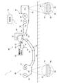
- FIG. 1 is a diagram showing a configuration of a manufacturing apparatus 1 for a membrane / catalyst layer assembly according to an embodiment of the present invention.
- the manufacturing apparatus 1 is an apparatus used in a manufacturing process of a membrane-electrode assembly (MEA) for a polymer electrolyte fuel cell.
- MEA membrane-electrode assembly
- the manufacturing apparatus 1 forms a catalyst layer on the surface of an electrolyte membrane, which is a long strip-shaped base material, and manufactures a membrane-catalyst-layer assembly (CCM: Catalyst-coated Membrane).
- CCM membrane-catalyst-layer assembly
- the apparatus 1 for manufacturing a membrane / catalyst layer assembly includes an adsorption roller 10, an electrolyte membrane supply unit 20, a coating unit 30, a catalyst layer detection unit 40, a drying furnace 50, a bonded body collection unit 60, and a control unit 70. .
- the adsorption roller 10 is a roller that rotates while adsorbing and holding the electrolyte membrane 90 as a base material.
- the suction roller 10 has a cylindrical outer peripheral surface having a plurality of suction holes.
- the diameter of the suction roller 10 is, for example, 200 mm to 1600 mm.
- a rotation drive unit having a drive source such as a motor is connected to the suction roller 10. When the rotation drive unit is operated, the suction roller 10 rotates around a horizontally extending axis.
- the suction roller 10 is an example of the “conveying unit” in the present invention.
- a porous material such as porous carbon or porous ceramics is used.
- the porous ceramic include a sintered body of alumina (Al 2 O 3 ) or silicon carbide (SiC).
- the pore diameter of the porous suction roller 10 is, for example, 5 ⁇ m or less, and the porosity is, for example, 15% to 50%.
- suction roller 10 may replace with a porous material for the material of the adsorption
- the metal include stainless steel such as SUS or iron.
- minute suction holes may be formed on the outer peripheral surface of the suction roller 10 by processing.
- the diameter of the suction hole is preferably 2 mm or less in order to prevent generation of suction marks.
- a suction port (not shown) is provided on the end face of the suction roller 10.
- the suction port is connected to a suction mechanism (for example, an exhaust pump).
- a suction mechanism for example, an exhaust pump.
- a negative pressure is also generated in the plurality of suction holes provided on the outer peripheral surface of the suction roller 10 through the pores in the suction roller 10.
- the electrolyte membrane 90 is conveyed in an arc shape by the rotation of the adsorption roller 10 while being adsorbed and held on the outer peripheral surface of the adsorption roller 10 by the negative pressure.
- the electrolyte membrane supply unit 20 supplies the laminated base material 92 to the suction roller 10.
- the laminated substrate 92 is composed of two layers, an electrolyte membrane 90 and a first support film 91.
- the electrolyte membrane supply unit 20 peels the first support film 91 from the electrolyte membrane 90 when supplying the laminated base material 92 to the suction roller 10. And while supplying the electrolyte membrane 90 to the adsorption
- the electrolyte membrane 90 for example, a fluorine-based or hydrocarbon-based polymer electrolyte membrane is used.
- the electrolyte membrane 90 include a polymer electrolyte membrane containing perfluorocarbon sulfonic acid (for example, Nafion (registered trademark) manufactured by DuPont, USA, Flemion (registered trademark) manufactured by Asahi Glass Co., Ltd., and Asahi Kasei Corporation. Aciplex (registered trademark), and Goreselect (registered trademark) manufactured by Gore Co., Ltd.).
- the thickness of the electrolyte membrane 90 is, for example, 5 ⁇ m to 30 ⁇ m.
- the electrolyte membrane 90 is swollen by moisture in the atmosphere, and contracts when the humidity is low. That is, the electrolyte membrane 90 has a property of being easily deformed according to the humidity in the atmosphere.
- the first support film 91 is a film for suppressing the deformation of the electrolyte membrane 90.
- a resin having a mechanical strength higher than that of the electrolyte membrane 90 and having an excellent shape holding function is used as the material of the first support film 91.
- Specific examples of the first support film 91 include a film of PEN (polyethylene naphthalate) or PET (polyethylene terephthalate).
- the film thickness of the first support film 91 is, for example, 25 ⁇ m to 100 ⁇ m.
- the electrolyte membrane supply unit 20 includes a laminated base material supply roller 21, a plurality of laminated base material carry-in rollers 22, a peeling roller 23, a plurality of first support film carry-out rollers 24, and a first support film collection roller 25.
- the laminated base material supply roller 21, the plurality of laminated base material carry-in rollers 22, the peeling roller 23, the plurality of first support film carry-out rollers 24, and the first support film collection roller 25 are all arranged in parallel with the suction roller 10.
- a laminated base material 92 is wound around the laminated base material supply roller 21 so that the first support film 91 is on the inner side.
- a catalyst layer (hereinafter referred to as “first catalyst layer 9A”) in advance on the surface of the electrolyte membrane 90 opposite to the first support film 91 (hereinafter referred to as “first surface”). Is formed.
- the first catalyst layer 9A is formed by intermittently applying a catalyst material on the first surface of the electrolyte membrane 90 and drying the catalyst material in an apparatus different from the manufacturing apparatus 1.
- the laminated base material supply roller 21 is rotated by the power of a motor (not shown). When the laminated base material supply roller 21 rotates, the laminated base material 92 is fed out from the laminated base material supply roller 21. The fed-out laminated base material 92 is conveyed to the peeling roller 23 along a predetermined carry-in route while being guided by a plurality of laminated base material carry-in rollers 22.
- FIG. 2 is an enlarged view of the vicinity of the suction roller 10.
- the peeling roller 23 is a roller for peeling the first support film 91 from the electrolyte membrane 90.
- the peeling roller 23 has a cylindrical outer peripheral surface whose diameter is smaller than that of the suction roller 10. At least the outer peripheral surface of the peeling roller 23 is formed of an elastic body.
- the peeling roller 23 is pressurized toward the suction roller 10 by an air cylinder (not shown).
- the laminated base material 92 carried in by the plurality of laminated base material carry-in rollers 22 is introduced between the suction roller 10 and the peeling roller 23.
- the porous substrate 99 is supplied to the suction roller 10 on the upstream side in the rotation direction of the suction roller 10.
- the porous base material 99 is conveyed in an arc shape by the rotation of the suction roller 10 while being held by suction on the outer peripheral surface of the suction roller 10.
- the first surface of the electrolyte membrane 90 of the laminated base material 92 introduced between the suction roller 10 and the peeling roller 23 is on the surface of the porous base material 99 held by the suction roller 10 together with the first catalyst layer 9A. Contact.
- the first support film 91 of the laminated base material 92 is in contact with the outer peripheral surface of the peeling roller 23.
- the suction roller 10 and the porous substrate 99 are illustrated with a space therebetween, and the porous substrate 99 and the electrolyte membrane 90 are also illustrated with a space therebetween. Yes.
- illustration regarding the porous base material 99 is abbreviate
- the laminated base material 92 is pressed against the suction roller 10 side by the pressure received from the peeling roller 23.
- a negative pressure is generated on the surface of the porous base material 99 held by the suction roller 10 due to the suction force from the suction roller 10.
- the electrolyte membrane 90 is adsorbed on the surface of the porous substrate 99 by the negative pressure.
- the electrolyte membrane 90 is conveyed in an arc shape by the rotation of the suction roller 10 while being held on the suction roller 10 together with the porous substrate 99.
- the first support film 91 is peeled from the electrolyte membrane 90.
- the surface (hereinafter referred to as “second surface”) opposite to the first surface of the electrolyte membrane 90 held by the suction roller 10 is exposed.
- the porous base material 99 is interposed between the outer peripheral surface of the suction roller 10 and the electrolyte membrane 90.
- the outer peripheral surface of the adsorption roller 10 and the first catalyst layer 9 ⁇ / b> A formed on the first surface of the electrolyte membrane 90 are not in direct contact. Therefore, it is possible to prevent a part of the first catalyst layer 9 ⁇ / b> A from adhering to the outer peripheral surface of the adsorption roller 10 or transferring foreign substances from the outer peripheral surface of the adsorption roller 10 to the electrolyte membrane 90.
- the porous base material 99 is collected away from the suction roller 10 on the downstream side in the rotation direction of the suction roller 10 with respect to a bonded body collection unit 60 described later.
- the first support film 91 peeled from the electrolyte membrane 90 is conveyed to the plurality of first support film carry-out roller 24 side.
- the first support film 91 is conveyed to the first support film collection roller 25 along a predetermined carry-out path while being guided by the plurality of first support film carry-out rollers 24.
- the first support film collection roller 25 is rotated by the power of a motor (not shown). As a result, the first support film 91 is wound around the first support film collection roller 25.
- the coating unit 30 is a mechanism that coats the second surface of the electrolyte membrane 90 around the suction roller 10 with a catalyst material that is a coating solution.
- a catalyst material for example, a catalyst material in which catalyst particles containing platinum (Pt) are dispersed in a solvent such as alcohol is used.
- the coating unit 30 includes a nozzle 31, an on-off valve 32, and a catalyst material supply source 33.
- the nozzle 31 is provided downstream of the peeling roller 23 in the conveying direction of the electrolyte membrane 90 by the adsorption roller 10.
- the nozzle 31 has a discharge port 311 that faces the outer peripheral surface of the suction roller 10.
- the discharge port 311 is a slit-like opening extending in the width direction of the suction roller 10 along the outer peripheral surface of the suction roller 10.
- the nozzle 31 forms a liquid pool of catalyst material at the tip of the discharge port 311. Then, the liquid reservoir is brought into contact with the coating area of the second surface of the electrolyte membrane 90 conveyed on the outer peripheral surface of the suction roller 10.
- the catalyst material is applied to the area to be coated on the second surface of the electrolyte membrane 90, and a wet film 9B of the catalyst material is formed.
- This wet film 9B becomes a catalyst layer (hereinafter referred to as “second catalyst layer 9C”) by being dried by a drying furnace 50 described later.
- the coating area is detected by the catalyst layer detection unit 40 disposed upstream of the nozzle 31 in the transport direction.
- This coated area is an area that overlaps the first catalyst layer 9 ⁇ / b> A formed on the first surface of the electrolyte membrane 90. That is, the first catalyst layer 9A and the second catalyst layer 9C are formed at overlapping positions.
- the catalyst layer detection unit 40 detects a plurality of coated areas where a plurality of wet films 9B which are a plurality of coating films are to be formed in the longitudinal direction.
- the on-off valve 32 executes or stops the discharge operation of the catalyst material by the nozzle 31.
- the on-off valve 32 is provided in the middle of a liquid supply pipe that connects the nozzle 31 and the catalyst material supply source 33.
- the on-off valve 32 is opened, the catalyst material is supplied from the catalyst material supply source 33 to the nozzle 31.
- a liquid pool of catalyst material is formed at the tip of the discharge port 311.
- the discharge operation by the nozzle 31 can be executed.
- the on-off valve 32 is closed, the supply of the catalyst material to the nozzle 31 is stopped. Thereby, formation of the liquid pool at the tip of the discharge port 311 is stopped, and the discharge operation of the catalyst material by the nozzle 31 is stopped.
- the catalyst particles in the catalyst material a material that causes a fuel cell reaction at the anode or cathode of the polymer fuel cell is used.
- particles of platinum (Pt), a platinum alloy, a platinum compound, etc. can be used as catalyst particles.
- platinum alloys include, for example, at least one selected from the group consisting of ruthenium (Ru), palladium (Pd), nickel (Ni), molybdenum (Mo), iridium (Ir), iron (Fe), and the like.
- An alloy of metal and platinum can be mentioned.
- platinum is used as the catalyst material for the cathode
- platinum alloy is used as the catalyst material for the anode.
- the catalyst material discharged from the nozzle 31 may be for the cathode or for the anode.
- catalyst materials having opposite polarities are used for the first catalyst layer 9A formed on the first surface of the electrolyte membrane 90 and the second catalyst layer 9C formed on the second surface of the electrolyte membrane 90.
- the catalyst layer detection unit 40 is disposed at a position facing the outer peripheral surface of the suction roller 10 and upstream of the coating unit 30 in the rotation direction of the suction roller 10.
- the catalyst layer detection unit 40 detects an area to be coated on the second surface of the electrolyte membrane 90 where the coating unit 30 should apply the catalyst material. As described above, the coated area is an area overlapping with the first catalyst layer 9A.
- the catalyst layer detection unit 40 detects the first catalyst layer 9 ⁇ / b> A formed on the first surface of the electrolyte membrane 90 from the second surface side of the electrolyte membrane 90 conveyed by the adsorption roller 10. Is detected.
- the catalyst layer detection unit 40 has a fiber sensor 41.
- the fiber sensor 41 is connected to the optical measurement device via an optical fiber (not shown).
- the optical measuring device has a light source and a light receiving unit. The light emitted from the light source of the optical measuring device is transmitted to the fiber sensor 41 via the optical fiber.
- the fiber sensor 41 irradiates the light transmitted through the optical fiber toward the second surface of the electrolyte membrane 90.
- the fiber sensor 41 receives the reflected light, and enters the received light into the light receiving unit of the optical measurement device via the optical fiber. Then, in the optical measurement device, the presence of the object is detected based on the incident light.
- the electrolyte membrane 90 is transparent. It is assumed that the first catalyst layer 9A has a color with a high extinction coefficient, such as black. In this case, the light emitted from the fiber sensor 41 passes through the electrolyte membrane 90. When the first catalyst layer 9A is present at the light irradiation destination, much of the light transmitted through the electrolyte membrane 90 is absorbed by the first catalyst layer 9A. On the other hand, if the first catalyst layer 9A does not exist at the light irradiation destination, the light transmitted through the electrolyte membrane 90 is reflected without being absorbed and reflected at another part (for example, the outer peripheral surface of the suction roller 10).
- the amount of reflected light received by the fiber sensor 41 varies depending on whether or not the first catalyst layer 9A exists at the light irradiation destination.
- the catalyst layer detection unit 40 detects the presence of the first catalyst layer 9A from the difference in the amount of light.
- the catalyst layer detector 40 can detect the first catalyst layer 9A formed on the first surface of the electrolyte membrane 90 from the second surface side of the electrolyte membrane 90.
- the catalyst layer detector 40 can be installed even when a sufficient space cannot be secured.
- the fiber sensor 41 is disposed close to the nozzle 31 of the coating unit 30. For this reason, the catalyst material can be applied to the detected coating region by starting the coating immediately after the catalyst layer detection unit 40 detects the coating region. That is, it is not necessary to transport the electrolyte membrane 90 only to detect the coating position. As a result, it is possible to prevent the electrolyte film 90 from having a region where the wet film 9B is not formed.
- the relationship between the detection timing of the coating area by the catalyst layer detection unit 40 and the coating start timing by the coating unit 30 will be described later.
- a sensor cover (detection unit cover) 41 ⁇ / b> A is provided between the fiber sensor 41 and the nozzle 31.
- the fiber sensor 41 is disposed close to the nozzle 31.
- the sensor cover 41 ⁇ / b> A prevents the catalyst material from the nozzle 31 from adhering to the fiber sensor 41.
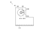
- the catalyst layer detection unit 40 has an angle adjustment mechanism 42 that adjusts the irradiation angle of the fiber sensor 41.
- FIG. 3 is a plan view of the angle adjustment mechanism 42. 4 is a cross-sectional view taken along line IV-IV in FIG.
- the catalyst layer detection unit 40 includes two fiber sensors 41.
- the two fiber sensors 41 are arranged at a distance along the width direction of the suction roller 10. That is, the catalyst layer detection unit 40 detects the area to be coated at two points in the width direction of the suction roller 10. Thereby, the detection precision of the to-be-coated area by the catalyst layer detection part 40 improves rather than the case where the fiber sensor 41 is one.
- the angle adjustment mechanism 42 has a pair of fixing brackets 421.
- the pair of fixed brackets 421 are disposed on the outside of the outer peripheral surface of the suction roller 10 so as to face each other at a wider interval than the length in the width direction of the suction roller 10.
- a sensor cover 41A and a rotating shaft 422 are provided between the pair of fixed brackets 421.
- the rotating shaft 422 has a cylindrical shape and extends in the width direction of the suction roller 10.
- the rotating shaft 422 is rotatably supported by a pair of fixed brackets 421.
- a fixing member 423 for fixing the two fiber sensors 41 is provided at a position on the rotating shaft 422 facing the outer peripheral surface of the suction roller 10. The fixing member 423 rotates with the rotation shaft 422.
- the rotating shaft 422 that is rotatable with respect to the pair of fixed brackets 421 is fixed to the fixed bracket 421 by being fastened by the split collar 424.
- the split collar 424 and the fixing bracket 421 are fixed with bolts 421A.
- the split collar 424 has a cylindrical shape having a columnar cavity in the axial direction.
- the split collar 424 has a notch 424A in a part of the circumferential portion, and has a C-shape in plan view from the axial direction.
- the diameter of the cavity of the split collar 424 is smaller than the diameter of the rotating shaft 422.
- the split collar 424 allows the rotation shaft 422 to be inserted in a state where the notch 424A is widened.
- the rotary shaft 422 is fixed to the split collar 424 by fastening the bolt 424B so that the notch 424A is narrowed with the rotary shaft 422 inserted into the cavity.
- the rotating shaft 422 rotates with respect to the pair of fixing brackets 421 by loosening (or removing) the bolts 421A and 424B.
- the two fiber sensors 41 fixed to the fixing member 423 also rotate. Thereby, the irradiation angle of the two fiber sensors 41 can be adjusted.
- the two fiber sensors 41 maintain a desired irradiation angle by tightening the bolt 421A and the bolt 424B and fixing the bolt 421A and the bolt 424B to the fixing bracket 421.
- the coated region can be detected more reliably.
- the first catalyst layer 9A is black or the like, the amount of reflected light changes depending on whether the first catalyst layer 9A is present or not present at the light irradiation destination. Large, the first catalyst layer 9A can be detected.
- the change in the amount of reflected light is small and it is difficult to detect the first catalyst layer 9A.
- the irradiation angle of the fiber sensor 41 with respect to the first catalyst layer 9A is vertical, the amount of reflected light scattered is small.
- the amount of reflected light received by the fiber sensor 41 is large, and the change in the amount of reflected light is small overall.
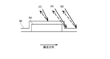
- FIG. 5 is a view for explaining an optimum irradiation angle of the fiber sensor 41 with respect to the transparent first catalyst layer 9A.
- the solid line arrow indicates irradiation light
- the broken line arrow indicates reflected light.
- the pattern (A), the pattern (B), and the pattern (C) in FIG. 5 have different reflection states.
- the amount of reflected light received by the fiber sensor 41 increases in the order of the pattern (B), the pattern (A), and the pattern (C) due to the difference in the amount of scattered light. From the difference in the amount of reflected light, the catalyst layer detection unit 40 can detect the area to be coated.
- the detection accuracy of the coated area can be improved.
- the drying furnace 50 is a part that dries the wet film 9 ⁇ / b> B formed on the second surface of the electrolyte film 90.
- the drying furnace 50 is disposed on the downstream side of the coating unit 30 in the conveying direction of the electrolyte membrane 90 by the adsorption roller 10.
- the drying furnace 50 is provided in an arc shape along the outer peripheral surface of the suction roller 10.
- the drying furnace 50 blows heated gas (hot air) on the second surface of the electrolyte membrane 90 around the adsorption roller 10. Then, the wet film 9B formed on the second surface of the electrolyte film 90 is heated, and the solvent in the catalyst material is vaporized.
- the wet film 9 ⁇ / b> B is dried, and the second catalyst layer 9 ⁇ / b> C is formed on the second surface of the electrolyte film 90.
- a membrane / catalyst layer assembly 95 composed of the electrolyte membrane 90, the first catalyst layer 9A, and the second catalyst layer 9C is obtained.
- the joined body collection unit 60 is a part that attaches the second support film 93 to the membrane / catalyst layer assembly 95 and collects the membrane / catalyst layer assembly 95.
- the joined body collection unit 60 includes a second support film supply roller 61, a plurality of second support film carry-in rollers 62, a laminating roller 63, a plurality of joined body carry-out rollers 64, and a joined body collection roller 65.
- the second support film supply roller 61, the plurality of second support film carry-in rollers 62, the laminating roller 63, the plurality of joined body carry-out rollers 64, and the joined body collection roller 65 are all arranged in parallel with the suction roller 10.
- a second support film 93 is wound around the second support film supply roller 61.
- the second support film supply roller 61 is rotated by the power of a motor (not shown).
- the second support film supply roller 61 rotates, the second support film 93 is fed out from the second support film supply roller 61.
- the fed-out second support film 93 is conveyed to the laminating roller 63 along a predetermined carry-in route while being guided by a plurality of second support film carry-in rollers 62.
- the material of the second support film 93 a resin having higher mechanical strength than the electrolyte membrane 90 and having an excellent shape holding function is used.
- the second support film 93 include PEN (polyethylene naphthalate) or PET (polyethylene terephthalate) films.
- the film thickness of the second support film 93 is, for example, 25 ⁇ m to 100 ⁇ m.
- the second support film 93 may be the same as the first support film 91.
- the first support film 91 wound around the first support film collection roller 25 may be fed out from the second support film supply roller 61 as the second support film 93.
- the laminating roller 63 is a roller for attaching the second support film 93 to the membrane / catalyst layer assembly 95.
- As the material of the laminating roller 63 for example, rubber having high heat resistance is used.
- the laminating roller 63 has a cylindrical outer peripheral surface having a smaller diameter than the suction roller 10.
- the laminating roller 63 is disposed adjacent to the suction roller 10 on the downstream side of the drying furnace 50 in the rotation direction of the suction roller 10.
- the laminating roller 63 is pressurized toward the suction roller 10 by an air cylinder (not shown).
- the second support film 93 carried in by the plurality of second support film carry-in rollers 62 is introduced between the membrane / catalyst layer assembly 95 and the laminating roller 63 conveyed around the adsorption roller 10. At this time, the second support film 93 is pressed against the membrane / catalyst layer assembly 95 by the pressure from the laminating roller 63 and is heated by the heat of the laminating roller 63. As a result, the second support film 93 is attached to the second surface of the electrolyte membrane 90.
- the second catalyst layer 9 ⁇ / b> C formed on the second surface of the electrolyte membrane 90 is sandwiched between the electrolyte membrane 90 and the second support film 93.
- the membrane / catalyst layer assembly 95 with the second support film 93 that has passed between the adsorption roller 10 and the laminating roller 63 is conveyed in a direction away from the adsorption roller 10. As a result, the membrane / catalyst layer assembly 95 is peeled from the porous substrate 99.
- a pressing roller 632 is disposed in the vicinity of the laminating roller 63.
- the pressing roller 632 is disposed adjacent to the laminating roller 63 on the downstream side in the transport direction of the membrane / catalyst layer assembly 95 with respect to the gap between the suction roller 10 and the laminating roller 63.
- the pressing roller 632 is pressed toward the laminating roller 63 by an air cylinder (not shown).
- the membrane / catalyst layer assembly 95 with the second support film 93 away from the porous base material 99 subsequently passes between the laminating roller 63 and the pressing roller 632. Thereby, the adhesiveness of the 2nd support film 93 with respect to the 2nd surface of the electrolyte membrane 90 improves.
- the membrane / catalyst layer assembly 95 with the second support film 93 is conveyed to the assembly recovery roller 65 along a predetermined delivery path while being guided by the plurality of assembly delivery rollers 64.
- the joined body collection roller 65 is rotated by the power of a motor (not shown).
- the membrane / catalyst layer assembly 95 with the second support film 93 is wound around the assembly recovery roller 65 so that the second support film 93 is on the outside.
- the control unit 70 is means for controlling the operation of each unit in the manufacturing apparatus 1.
- FIG. 6 is a block diagram showing connections between the control unit 70 and each unit in the manufacturing apparatus 1.
- the control unit 70 is configured by a computer having an arithmetic processing unit 71 such as a CPU, a memory 72 such as a RAM, and a storage unit 73 such as a hard disk drive.
- a computer program P for executing the manufacturing process of the membrane / catalyst layer assembly is installed in the storage unit 73.
- the control unit 70 includes the rotation driving unit of the suction roller 10, the suction mechanism of the suction roller 10, the motor of the laminated base material supply roller 21, the air cylinder of the peeling roller 23, and the first support.
- the cylinder, the heater 631 of the laminating roller 63, the air cylinder of the pressing roller 632, and the motor of the joined body collecting roller 65 are connected to be communicable with each other.
- the control unit 70 temporarily reads the computer program P and data stored in the storage unit 73 into the memory 72, and the arithmetic processing unit 71 performs arithmetic processing based on the computer program P, whereby each of the above units is performed. Control the operation. Thereby, the manufacturing process of the membrane / catalyst layer assembly in the manufacturing apparatus 1 proceeds.
- FIG. 7 is a diagram for explaining the arrangement relationship between the nozzle 31 and the fiber sensor 41.
- FIG. 7 is a view of the electrolyte membrane 90 held by the suction roller 10 as viewed from the second surface side.
- start end one end of the first catalyst layer 9A on the downstream side in the transport direction
- terminal the other end of the first catalyst layer 9A on the upstream side in the transport direction
- the distance between the coating position of the catalyst material by the nozzle 31 and the light irradiation position by the fiber sensor 41 is represented by d1. Further, the distance between the start end of one first catalyst layer 9A on the downstream side in the transport direction and the start end of the first catalyst layer 9A adjacent to the first catalyst layer 9A in the transport direction, This is represented by d2. In this case, the nozzle 31 and the fiber sensor 41 are arranged satisfying the relationship of d1 ⁇ d2.
- FIG. 8 is a time chart for explaining the detection timing of the first catalyst layer 9A and the coating timing of the catalyst material.
- Timing A2 shown in FIG. 8 is timing when the catalyst layer detector 40 detects the end of the first catalyst layer 9A.
- the time from timing A1 to timing A2 is represented by T1.
- the coating unit 30 is a timing at which the coating unit 30 starts coating the catalyst material.
- the coating unit 30 starts coating the catalyst material after the time T2 ( ⁇ T1) has elapsed from the timing A1.
- the time T2 is calculated from the distance d1 shown in FIG. 7 and the rotation speed of the suction roller 10. That is, the time T2 is the time from when the start end of the first catalyst layer 9A formed on the conveyed electrolyte membrane 90 passes through the light irradiation position to the coating position.
- time T1 is the time from when the catalyst layer detection unit 40 detects the start end of the first catalyst layer 9A until the end is detected.
- time T1 is the movement time of the coated area in the transport direction.
- the coating unit 30 may start coating when the moving distance of the suction roller 10 converted from the driving pulse of the suction roller 10 reaches the distance d1 from the timing A1.
- the nozzle 31 and the fiber sensor 41 are arranged close to each other, and the coating of the catalyst material can be applied to the detected coating region by starting the coating immediately after the detection of the coating region. . That is, it is not necessary to transport the electrolyte membrane 90 only to detect the coating position. As a result, it is possible to prevent the electrolyte membrane 90 from being transported in a state where the wet film 9 ⁇ / b> B is not formed and forming a useless region in the electrolyte membrane 90.
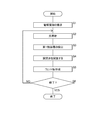
- FIG. 9 is a flowchart showing a flow during coating by the coating unit 30.
- the electrolyte membrane 90 is transported in the transport direction at a predetermined transport speed (step S1).
- light is irradiated from the fiber sensor 41 of the catalyst layer detection unit 40 while continuing to convey the electrolyte membrane 90 (step S2).
- the catalyst layer detection unit 40 detects the first catalyst layer 9A by receiving the reflected light (step S3). Specifically, the catalyst layer detection unit 40 detects the start end of the first catalyst layer 9A.
- the coating unit 30 opens the on-off valve 32 (step S4), starts coating of the catalyst material, and forms the wet film 9B (step S5).
- step S5 the coating unit 30 starts coating the catalyst material after a lapse of time T2 after the catalyst layer detection unit 40 detects the start end of the first catalyst layer 9A in step S3. Then, the catalyst material is continuously applied for the time T1. Thereby, in the 2nd surface of the electrolyte membrane 90, an electronic material can be apply
- step S6 When the coating process is finished (YES in step S6), this process is finished. If the coating process is not terminated (NO in step S6), the process of step S2 is executed.
- finished is a case where the manufacture of the manufacturing apparatus 1 is stopped, a case where conveyance of the electrolyte membrane 90 is stopped, and the like.
- the membrane-catalyst layer assembly manufacturing apparatus 1 of the above embodiment applies the catalyst material to the second surface opposite to the first surface where the first catalyst layer 9A is formed on the electrolyte membrane 90.
- the apparatus for manufacturing a membrane / catalyst layer assembly may have a configuration in which the catalyst material is overcoated on the first catalyst layer 9A.
- the first catalyst layer 9 ⁇ / b> A is formed on the second surface of the electrolyte membrane 90.
- the catalyst layer detection unit 40 detects the first catalyst layer 9A formed on the second surface of the electrolyte membrane 90 as a coating region.
- the coating part 30 applies a catalyst material with respect to the to-be-coated area
- the electrolyte membrane 90 may be formed with a frame, and the membrane / catalyst layer assembly manufacturing apparatus may be configured to apply a catalyst material to the frame.
- the catalyst layer detection unit 40 detects the inside of the frame body of the electrolyte membrane 90 as a coating area. And the coating part 30 applies a catalyst material with respect to the inner side of the frame.
Landscapes
- Engineering & Computer Science (AREA)
- Chemical & Material Sciences (AREA)
- Manufacturing & Machinery (AREA)
- Chemical Kinetics & Catalysis (AREA)
- Electrochemistry (AREA)
- General Chemical & Material Sciences (AREA)
- Life Sciences & Earth Sciences (AREA)
- Sustainable Development (AREA)
- Sustainable Energy (AREA)
- Wood Science & Technology (AREA)
- Fuel Cell (AREA)
- Inert Electrodes (AREA)
- Coating Apparatus (AREA)
- Application Of Or Painting With Fluid Materials (AREA)
Abstract
Description
図1は、本発明の実施形態に係る膜・触媒層接合体の製造装置1の構成を示した図である。この製造装置1は、固体高分子形燃料電池用の膜・電極接合体(MEA:Membrane-Electrode-Assembly)の製造過程に用いられる装置である。製造装置1は、長尺帯状の基材である電解質膜の表面に触媒層を形成して、膜・触媒層接合体(CCM:Catalyst-coated Membrane)を製造する。
<2.1.ノズル31とファイバーセンサ41との配置について>
図7は、ノズル31と、ファイバーセンサ41との配置関係を説明するための図である。図7は、吸着ローラ10に保持される電解質膜90を、第2面側から視た図である。以下の説明では、搬送方向の下流側となる、第1触媒層9Aの一端を「開始端」と称する。また、搬送方向の上流側となる、第1触媒層9Aの他端を「終端」と称する。
図8は、第1触媒層9Aの検出タイミングと、触媒材料の塗工タイミングとを説明するためのタイムチャートである。
図9は、塗工部30による塗工時の流れを示すフローチャートである。
9A 第1触媒層
9B ウェット膜
9C 第2触媒層
10 吸着ローラ
30 塗工部
31 ノズル
40 触媒層検知部
41 ファイバーセンサ
41A センサカバー(検出部用カバー)
42 角度調節機構
50 乾燥炉
70 制御部
71 演算処理部
72 メモリ
73 記憶部
90 電解質膜
91 第1支持フィルム
92 積層基材
93 第2支持フィルム
95 膜・触媒層接合体
311 吐出口
421 固定ブラケット
422 回転軸
423 固定部材
424 割りカラー
Claims (8)
- 長尺帯状であって、複数の塗膜を長手方向に形成すべき複数の被塗工領域を、前記長手方向に沿って有する基材を、前記長手方向に搬送する搬送部と、
光を照射して被塗工領域を検出する検出部と、
前記検出部よりも、搬送方向の下流側に配置され、前記検出部が検出する被塗工領域に対して、塗工液を塗工する塗工部と、
を備え、
前記検出部は、
前記搬送方向の下流側となる、被塗工領域の開始端を検出し、
前記塗工部は、
前記検出部が前記被塗工領域の開始端を検出するタイミングに応じて、塗工液の塗工を開始し、
前記塗工部による塗工位置と、前記検出部の光照射位置との距離は、前記搬送方向に連続する2つの被塗工領域の開始端の間の距離よりも、短い、
塗工装置。 - 請求項1に記載の塗工装置において、
前記搬送部は、外周面で前記基材を保持しつつ回転するローラを有し、
前記検出部は、
前記ローラの外周面で保持される前記基材に対して光を照射し、
前記塗工部は、
前記ローラの外周面で保持される前記基材に対して、塗工液を塗工する、
塗工装置。 - 請求項1または請求項2に記載の塗工装置において、
前記検出部は、光の照射角度が調整可能である、
塗工装置。 - 請求項1から請求項3までのいずれか一つに記載の塗工装置において、
前記検出部は、前記基材の幅方向に沿った複数の位置で、被塗工領域を検出する、
塗工装置。 - 請求項1から請求項4までのいずれか1つに記載の塗工装置において、
前記塗工部と、前記検出部との間に設けられた検出部用カバー、
を備える塗工装置。 - 請求項1から請求項5までのいずれか1つに記載の塗工装置において、
前記検出部は、
前記被塗工領域で反射した反射光を受光することで、前記被塗工領域を検出し、
前記塗工部は、
前記検出部が前記反射光を受光し続ける時間と同じ時間、塗工液を塗工する、
塗工装置。 - 請求項1から請求項6までのいずれか1つに記載の塗工装置において、
前記検出部は、ファイバーセンサを含む、
塗工装置。 - a)長尺帯状であって、複数の塗膜を長手方向に形成すべき複数の被塗工領域を、前記長手方向に沿って有する基材を、前記長手方向に搬送する工程と、
b)光を照射して被塗工領域を検出部で検出する工程と、
c)前記検出部よりも、搬送方向の下流側において、前記検出部が検出する被塗工領域に対して、塗工部で塗工液を塗工する工程と、
を備え、
前記工程b)では、
前記搬送方向の下流側となる、被塗工領域の開始端を検出し、
前記工程c)では、
前記工程b)で前記被塗工領域の開始端が検出されるタイミングに応じて、塗工液の塗工を開始し、
前記塗工部による塗工位置と、前記検出部の光照射位置との距離は、前記搬送方向に連続する2つの被塗工領域の開始端の間の距離よりも、短い、
塗工方法。
Priority Applications (3)
| Application Number | Priority Date | Filing Date | Title |
|---|---|---|---|
| CN201780087788.6A CN110382123B (zh) | 2017-03-17 | 2017-12-01 | 涂敷装置以及涂敷方法 |
| KR1020197023813A KR102325722B1 (ko) | 2017-03-17 | 2017-12-01 | 도공 장치 및 도공 방법 |
| EP17901031.9A EP3597310A4 (en) | 2017-03-17 | 2017-12-01 | COATING DEVICE AND COATING METHOD |
Applications Claiming Priority (2)
| Application Number | Priority Date | Filing Date | Title |
|---|---|---|---|
| JP2017052020A JP6869061B2 (ja) | 2017-03-17 | 2017-03-17 | 塗工装置および塗工方法 |
| JP2017-052020 | 2017-03-17 |
Publications (1)
| Publication Number | Publication Date |
|---|---|
| WO2018168105A1 true WO2018168105A1 (ja) | 2018-09-20 |
Family
ID=63522927
Family Applications (1)
| Application Number | Title | Priority Date | Filing Date |
|---|---|---|---|
| PCT/JP2017/043226 Ceased WO2018168105A1 (ja) | 2017-03-17 | 2017-12-01 | 塗工装置および塗工方法 |
Country Status (5)
| Country | Link |
|---|---|
| EP (1) | EP3597310A4 (ja) |
| JP (1) | JP6869061B2 (ja) |
| KR (1) | KR102325722B1 (ja) |
| CN (1) | CN110382123B (ja) |
| WO (1) | WO2018168105A1 (ja) |
Cited By (1)
| Publication number | Priority date | Publication date | Assignee | Title |
|---|---|---|---|---|
| CN111495702A (zh) * | 2020-05-26 | 2020-08-07 | 苏州凌威新能源科技有限公司 | 极片涂布尺寸的检测控制系统和方法 |
Families Citing this family (7)
| Publication number | Priority date | Publication date | Assignee | Title |
|---|---|---|---|---|
| CN114226164A (zh) * | 2021-12-18 | 2022-03-25 | 惠州市信宇人科技有限公司 | 电极材料的涂布方法、精密程控式涂布供料的呑吐阀及其涂布头 |
| KR20240029920A (ko) * | 2022-08-29 | 2024-03-07 | 주식회사 엘지에너지솔루션 | 기준점 마킹장치 및 롤맵 생성장치 |
| KR20240030375A (ko) * | 2022-08-30 | 2024-03-07 | 주식회사 엘지에너지솔루션 | 기준점 마킹장치 및 롤맵 생성장치 |
| CN115430569B (zh) * | 2022-09-21 | 2025-06-17 | 佛山市冰蓝科技有限公司 | 一种自动制作光纤编码湿度增敏的系统及方法 |
| CN115301502B (zh) * | 2022-09-29 | 2023-03-24 | 江苏友恒健身器材有限公司 | 一种瑜伽垫面料生产用涂覆装置 |
| KR20260039456A (ko) * | 2024-09-13 | 2026-03-20 | 삼성에스디아이 주식회사 | 코팅 장치 및 방법 |
| DE102024129743A1 (de) * | 2024-10-14 | 2026-04-16 | Ionysis Gmbh | Beschichtungsvorrichtung zum Beschichten einer transportierten Membran mit einer Katalysatorschicht-Tinte, Verfahren zur intermittierenden Beschichtung einer transportierten Membran mit einer Katalysatorschicht-Tinte |
Citations (6)
| Publication number | Priority date | Publication date | Assignee | Title |
|---|---|---|---|---|
| JPH05111658A (ja) | 1991-04-30 | 1993-05-07 | Kanebo Nsc Ltd | 間欠塗工位置ずれ防止装置 |
| JP2004195348A (ja) * | 2002-12-18 | 2004-07-15 | Akatsuki Kinzoku Kogyo:Kk | 塗工シート加工装置および貼付剤 |
| JP2011206641A (ja) * | 2010-03-29 | 2011-10-20 | Toppan Printing Co Ltd | 両面間欠塗布装置 |
| JP2012130907A (ja) * | 2010-12-02 | 2012-07-12 | Fuji Kikai Kogyo Kk | 間欠塗工装置 |
| WO2015019711A1 (ja) * | 2013-08-06 | 2015-02-12 | Necエナジーデバイス株式会社 | 間欠塗布電池電極製造方法 |
| JP2016039102A (ja) * | 2014-08-11 | 2016-03-22 | 株式会社Screenホールディングス | 膜・触媒層接合体の製造装置および製造方法 |
Family Cites Families (8)
| Publication number | Priority date | Publication date | Assignee | Title |
|---|---|---|---|---|
| JP3744574B2 (ja) * | 1995-10-20 | 2006-02-15 | Tdk株式会社 | 間欠塗布方法 |
| JPH10170242A (ja) * | 1996-12-12 | 1998-06-26 | Sharp Corp | シール剤塗布検査方法及びその装置 |
| JP5711031B2 (ja) * | 2011-03-31 | 2015-04-30 | 株式会社Screenホールディングス | 塗布装置および塗布膜形成システム |
| EP2799154A1 (en) * | 2013-05-03 | 2014-11-05 | Nederlandse Organisatie voor toegepast -natuurwetenschappelijk onderzoek TNO | Slot-die coating method, apparatus, and substrate |
| JP2014229370A (ja) * | 2013-05-20 | 2014-12-08 | 大日本スクリーン製造株式会社 | 複合膜の製造装置および製造方法 |
| JP6294163B2 (ja) * | 2014-06-05 | 2018-03-14 | 株式会社鈴野製作所 | 半田塗布装置 |
| JP6428536B2 (ja) * | 2014-08-29 | 2018-11-28 | 日産自動車株式会社 | 塗膜を形成したシート材の製造装置、および塗膜を形成したシート材の製造方法 |
| JP2016138684A (ja) * | 2015-01-27 | 2016-08-04 | 株式会社Screenホールディングス | 乾燥装置および乾燥方法 |
-
2017
- 2017-03-17 JP JP2017052020A patent/JP6869061B2/ja active Active
- 2017-12-01 CN CN201780087788.6A patent/CN110382123B/zh active Active
- 2017-12-01 WO PCT/JP2017/043226 patent/WO2018168105A1/ja not_active Ceased
- 2017-12-01 EP EP17901031.9A patent/EP3597310A4/en active Pending
- 2017-12-01 KR KR1020197023813A patent/KR102325722B1/ko active Active
Patent Citations (6)
| Publication number | Priority date | Publication date | Assignee | Title |
|---|---|---|---|---|
| JPH05111658A (ja) | 1991-04-30 | 1993-05-07 | Kanebo Nsc Ltd | 間欠塗工位置ずれ防止装置 |
| JP2004195348A (ja) * | 2002-12-18 | 2004-07-15 | Akatsuki Kinzoku Kogyo:Kk | 塗工シート加工装置および貼付剤 |
| JP2011206641A (ja) * | 2010-03-29 | 2011-10-20 | Toppan Printing Co Ltd | 両面間欠塗布装置 |
| JP2012130907A (ja) * | 2010-12-02 | 2012-07-12 | Fuji Kikai Kogyo Kk | 間欠塗工装置 |
| WO2015019711A1 (ja) * | 2013-08-06 | 2015-02-12 | Necエナジーデバイス株式会社 | 間欠塗布電池電極製造方法 |
| JP2016039102A (ja) * | 2014-08-11 | 2016-03-22 | 株式会社Screenホールディングス | 膜・触媒層接合体の製造装置および製造方法 |
Non-Patent Citations (1)
| Title |
|---|
| See also references of EP3597310A4 |
Cited By (2)
| Publication number | Priority date | Publication date | Assignee | Title |
|---|---|---|---|---|
| CN111495702A (zh) * | 2020-05-26 | 2020-08-07 | 苏州凌威新能源科技有限公司 | 极片涂布尺寸的检测控制系统和方法 |
| CN111495702B (zh) * | 2020-05-26 | 2023-10-27 | 湖南领湃达志科技股份有限公司 | 极片涂布尺寸的检测控制系统和方法 |
Also Published As
| Publication number | Publication date |
|---|---|
| CN110382123A (zh) | 2019-10-25 |
| CN110382123B (zh) | 2021-09-10 |
| EP3597310A1 (en) | 2020-01-22 |
| JP2018153746A (ja) | 2018-10-04 |
| KR102325722B1 (ko) | 2021-11-11 |
| EP3597310A4 (en) | 2020-04-15 |
| KR20190107092A (ko) | 2019-09-18 |
| JP6869061B2 (ja) | 2021-05-12 |
Similar Documents
| Publication | Publication Date | Title |
|---|---|---|
| JP6869061B2 (ja) | 塗工装置および塗工方法 | |
| KR102129217B1 (ko) | 도공 장치 및 필름 회수 방법 | |
| JP6352730B2 (ja) | 膜・触媒層接合体の製造装置および製造方法 | |
| JP6352727B2 (ja) | 膜・触媒層接合体の製造装置および製造方法 | |
| JP2016046091A (ja) | 塗工装置および塗工方法、並びに、膜・触媒層接合体の製造装置および製造方法 | |
| EP3208879B1 (en) | Apparatus for manufacturing membrane electrode assembly | |
| JP2016138684A (ja) | 乾燥装置および乾燥方法 | |
| KR102038763B1 (ko) | 기재 처리 장치 및 기재 처리 방법 | |
| WO2017086078A1 (ja) | 塗布装置、製造装置および測定方法 | |
| JP6868962B2 (ja) | 膜・電極層接合体の製造装置および製造方法 | |
| KR102269977B1 (ko) | 도공 장치 및 도공 방법 | |
| JP6541531B2 (ja) | 膜・触媒層接合体の製造装置および製造方法 | |
| JP2017142897A (ja) | 膜・触媒層接合体の製造装置および製造方法 | |
| KR102272864B1 (ko) | 지지 필름, 첩부 방법, 막·전극 접합체의 제조 방법 및 제조 장치 | |
| KR102038762B1 (ko) | 도포 장치 및 도포 방법 | |
| JP6586336B2 (ja) | 接続方法、塗工方法、接続装置および塗工装置 | |
| JP2017068898A (ja) | 膜・触媒層接合体の製造方法および製造装置 | |
| JP2018147890A (ja) | 膜・触媒層接合体の製造装置 | |
| JP2020017374A (ja) | 基材処理装置および基材処理方法 |
Legal Events
| Date | Code | Title | Description |
|---|---|---|---|
| 121 | Ep: the epo has been informed by wipo that ep was designated in this application |
Ref document number: 17901031 Country of ref document: EP Kind code of ref document: A1 |
|
| ENP | Entry into the national phase |
Ref document number: 20197023813 Country of ref document: KR Kind code of ref document: A |
|
| NENP | Non-entry into the national phase |
Ref country code: DE |
|
| WWE | Wipo information: entry into national phase |
Ref document number: 2017901031 Country of ref document: EP |
|
| ENP | Entry into the national phase |
Ref document number: 2017901031 Country of ref document: EP Effective date: 20191017 |