WO2018168573A1 - 尿素の造粒方法 - Google Patents
尿素の造粒方法 Download PDFInfo
- Publication number
- WO2018168573A1 WO2018168573A1 PCT/JP2018/008574 JP2018008574W WO2018168573A1 WO 2018168573 A1 WO2018168573 A1 WO 2018168573A1 JP 2018008574 W JP2018008574 W JP 2018008574W WO 2018168573 A1 WO2018168573 A1 WO 2018168573A1
- Authority
- WO
- WIPO (PCT)
- Prior art keywords
- aqueous solution
- urea
- urea aqueous
- ammonium salt
- recovered
- Prior art date
- Legal status (The legal status is an assumption and is not a legal conclusion. Google has not performed a legal analysis and makes no representation as to the accuracy of the status listed.)
- Ceased
Links
Images
Classifications
-
- C—CHEMISTRY; METALLURGY
- C07—ORGANIC CHEMISTRY
- C07C—ACYCLIC OR CARBOCYCLIC COMPOUNDS
- C07C273/00—Preparation of urea or its derivatives, i.e. compounds containing any of the groups, the nitrogen atoms not being part of nitro or nitroso groups
- C07C273/02—Preparation of urea or its derivatives, i.e. compounds containing any of the groups, the nitrogen atoms not being part of nitro or nitroso groups of urea, its salts, complexes or addition compounds
- C07C273/14—Separation; Purification; Stabilisation; Use of additives
- C07C273/16—Separation; Purification
-
- B—PERFORMING OPERATIONS; TRANSPORTING
- B01—PHYSICAL OR CHEMICAL PROCESSES OR APPARATUS IN GENERAL
- B01J—CHEMICAL OR PHYSICAL PROCESSES, e.g. CATALYSIS OR COLLOID CHEMISTRY; THEIR RELEVANT APPARATUS
- B01J2/00—Processes or devices for granulating materials, e.g. fertilisers in general; Rendering particulate materials free flowing in general, e.g. making them hydrophobic
-
- C—CHEMISTRY; METALLURGY
- C07—ORGANIC CHEMISTRY
- C07C—ACYCLIC OR CARBOCYCLIC COMPOUNDS
- C07C275/00—Derivatives of urea, i.e. compounds containing any of the groups, the nitrogen atoms not being part of nitro or nitroso groups
Definitions
- the present invention relates to a urea granulation method for producing granular solid urea from an aqueous urea solution.
- urea In the urea plant, urea is synthesized, and then granular solid urea is produced as the main product.
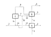
- the flow of the conventional urea granulation process will be described with reference to FIG.
- a raw urea aqueous solution containing a small amount of ammonia is supplied to the urea granulation process.
- a concentrated and recovered urea aqueous solution (line 9) described later is mixed with the raw urea aqueous solution, and the mixed solution (line 11) is sent to the granulating step A.
- granular solid urea (line 2) is produced from the urea aqueous solution using air supplied from the line 3.
- air containing urea dust and ammonia hereinafter sometimes referred to as “granulation outlet gas”) is extracted (line 4) and sent to the recovery step B.
- Recovered water (line 5) to which acid has been added is supplied to the recovery step B.
- urea dust in the granulation outlet gas is recovered in the recovered urea aqueous solution (line 7), and ammonia in the granulation outlet gas is recovered as an ammonium salt (the acid salt).
- exhaust gas from which urea dust and ammonia have been removed is released to the atmosphere (line 6).
- a concentration step C is performed in which moisture is removed from the recovered urea aqueous solution (line 7) to generate a concentrated recovered urea aqueous solution (line 9).
- the concentrated and recovered urea aqueous solution (line 9) containing ammonium salt obtained from the concentration step C is mixed with the raw material urea aqueous solution supplied from the line 1 (line 11), and then supplied to the granulation step A.
- the water removed from the recovered urea aqueous solution in the concentration step C is discharged from the line 8.
- the concentration of the ammonium salt is increased in the concentration step C, so that the ammonium salt may be precipitated.
- the ammonium salt is precipitated, for example, a strainer of a pump for transferring a concentrated urea aqueous solution or a spray nozzle used in the granulation process may be clogged, which may hinder long-term continuous operation.
- Patent Document 1 discloses a method for recovering and using urea dust and ammonia in exhaust gas.
- a first washing tower (recovering urea dust with an aqueous urea solution not containing acid) and a second washing tower (with an acid aqueous solution to which acid has been added, ammonia and the first washing tower).
- the urea dust that could not be absorbed by the is set to 20% or more, and this recovered urea aqueous solution is converted into a urea aqueous solution supplied to the granulation step without going through the concentration step. Mix.
- Patent Document 2 a part of the molten urea supplied to the system is added to the recovered urea aqueous solution before concentration, and the concentration of the ammonium salt contained in the urea solution at the outlet of the concentration step (evaporator) is less than 12 wt%.
- a method of supplying 9 to 11 wt% of the molten urea supplied to the granulation step and supplying the remainder of the molten urea supplied to the system to the granulation step has been proposed. However, in this method, it is recommended to minimize the amount of molten urea added to the recovered urea aqueous solution before concentration.
- the object of the present invention is to suppress an increase in the amount of water in the urea aqueous solution supplied to the urea granulation process when recovering and utilizing urea and ammonia in the gas containing urea dust and ammonia generated from the urea granulation process. While preventing precipitation of the ammonium salt.
- a granulation process for producing granular solid urea using air from a raw urea aqueous solution Recovery process for obtaining a recovered urea aqueous solution, which is an aqueous solution containing urea and ammonium salts, by recovering urea dust and ammonia from the air containing urea dust and ammonia discharged from the granulation process using an aqueous solution containing acid.
- Ammonium salt concentration adjusting step for adjusting the ammonium salt concentration in the recovered urea aqueous solution by mixing the recovered urea aqueous solution obtained from the recovery step with a urea aqueous solution having a relatively low ammonium salt concentration compared to the recovered urea aqueous solution.
- the ammonium salt concentration is relative in the ammonium salt concentration adjusting step.
- the granulation method may have a neutralization step for neutralizing the recovered urea aqueous solution before the concentration step by adding alkali to the recovered urea aqueous solution obtained from the recovery step.
- the flow rate of the urea aqueous solution having a relatively low ammonium salt concentration mixed with the recovered urea aqueous solution in the ammonium salt concentration adjusting step is operated.
- a control step of controlling the ammonium salt concentration of the concentrated and recovered urea aqueous solution it is possible to have a control step of controlling the ammonium salt concentration of the concentrated and recovered urea aqueous solution.
- the current value of the ammonium salt concentration of the concentrated and recovered urea aqueous solution can be obtained based on the temperature and pressure of water evaporation in the concentration step and the temperature and density of the concentrated and recovered urea aqueous solution.
- the acid may be at least one acid selected from sulfuric acid, nitric acid and phosphoric acid.
- the granulation method can include a step of supplying the water evaporated in the concentration step to the recovery step.
- urea and ammonia in a gas containing urea dust and ammonia generated from the urea granulation process are recovered and used, an increase in the amount of water in the urea aqueous solution supplied to the urea granulation process is suppressed. Meanwhile, precipitation of the ammonium salt can be prevented.
- a granulation step a recovery step, an ammonium salt concentration adjustment step, a concentration step, and a mixing step are performed.
- a granulation step a recovery step, an ammonium salt concentration adjustment step, a concentration step, and a mixing step are performed.
- the raw urea aqueous solution (line 1) supplied to the urea granulation process according to the present invention is usually concentrated by separating the water in the urea aqueous solution from the urea aqueous solution obtained from the urea synthesis process. Is a high urea aqueous solution. Usually, the urea concentration of the raw urea aqueous solution is 95 mass% or more and 98 mass% or less. Originating from the urea synthesis process, the raw urea aqueous solution contains a trace amount of free ammonia. The ammonia concentration of the starting urea aqueous solution is usually 1000 to 1500 ppm by mass. Usually, in the granulation step, a small amount of ammonia is generated as a result of hydrolysis and biuret formation reaction in an aqueous urea solution.
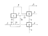
- a liquid (line 11) obtained by mixing the raw urea aqueous solution and the concentrated recovered urea aqueous solution is branched, and a part (line 12) is supplied to the granulating step A, and the remainder (line 10) is mixed with the recovered urea aqueous solution (line 13) in the ammonium salt concentration adjusting step. Therefore, urea in the aqueous urea solution introduced from the line 12 to the granulation step A is solidified and cooled by the air supplied from the line 3 to become solid urea, and is taken out from the line 2 as a product.
- solid urea can be produced using a known granulator as appropriate.
- a urea granulator using a fluidized bed or a fluidized / spouted bed is used.
- the shape and size of the solid urea particles are not particularly limited and can be determined as appropriate.
- air (granulation outlet gas) containing urea dust and ammonia is extracted (line 4).
- the urea dust concentration is 3000 to 10000 ppm by mass
- the ammonia concentration is 100 to 300 ppm by mass.
- the air discharged from the cooler may also contain urea dust and further ammonia. Therefore, the air exhausted from the cooler can be treated in the recovery process in the same manner as the air exhausted from the granulation process.
- composition of the solid urea depends on individual requirements. Typically, for example, urea is 98.5 to 99.5% by mass, moisture is 0.1 to 0.5% by mass, and ammonium salt is 0%. .2 to 1.0% by mass.
- recovered urea aqueous solution (line 13) is obtained by recovering urea dust and ammonia from the granulation outlet gas (line 4) using an aqueous solution containing an acid.
- a known washing tower such as a packed bed system or a venturi system filled with a packing material can be used.
- urea dust and ammonia are recovered in the cleaning liquid by circulating the cleaning liquid in the cleaning tower and bringing the granulation outlet gas and the cleaning liquid into gas-liquid contact.
- a part of the cleaning liquid (mixed aqueous solution containing urea, ammonium salt and acid) is taken out from the recovery device as recovered urea aqueous solution (line 13) (the remainder is the recovery device) In contact with the granulation outlet gas).
- water containing acid make-up water
- urea dust and ammonia in the granulation outlet gas are absorbed in an aqueous solution containing an acid. At this time, ammonia is absorbed as an ammonium salt.
- the pH of the cleaning liquid can be adjusted to about 2 to 7 using an acid.
- an acid at least one acid selected from sulfuric acid, nitric acid and phosphoric acid can be used, and in particular, sulfuric acid can be used.
- supplementary water to which an acid has been added (line 5) and water obtained from the concentration step C (line 8, which may contain urea, ammonium salt and ammonia at low concentrations) are also available. Used as makeup water to be supplied to the recovery process.
- the urea concentration is, for example, 40 to 60% by mass
- the ammonium salt concentration is, for example, 1 to 10% by mass
- the pH is, for example, 2 to 7. The same applies to the recovered urea aqueous solution (line 13).
- the urea concentration and ammonia concentration of the makeup water need only be thinner than this cleaning solution.
- the urea concentration and ammonia concentration of make-up water may each be 1% by mass or less. More specifically, for the water in line 8, for example, urea is 0 to 0.5% by mass, ammonia is 0 to 0.5% by mass, and ammonium salt is 0 to 0.01% by mass.
- urea is 0 to 5 ppm by mass and ammonia is 0 to 5 ppm by mass.
- the urea and ammonia concentrations in the exhaust gas are usually, for example, 30 to 50 ppm by mass for urea and 30 to 50 ppm by mass for ammonia.
- the urea aqueous solution (line 10) having a lower ammonium salt concentration than the recovered urea aqueous solution (line 13) is added to the recovered urea aqueous solution (line 13) to obtain a recovered urea aqueous solution (line 7) having a reduced ammonium salt concentration.
- the mixing amount of the low ammonium salt concentration urea aqueous solution is determined so that the ammonium salt concentration in the concentrated recovered urea aqueous solution (line 9) is 7% by mass or less.
- a part (line 10) of the mixed solution (line 11) of the raw urea aqueous solution (line 1) and the concentrated recovered urea aqueous solution (line 9) is used as the low ammonium salt concentration urea aqueous solution. . That is, a part of the raw urea aqueous solution (line 10) after the concentrated recovered urea aqueous solution is mixed is used as the low ammonium salt concentration urea aqueous solution in the ammonium salt concentration adjustment step.
- the raw urea aqueous solution (line 1) may be branched and a part (line 16) may be mixed with the recovered urea aqueous solution (line 13) as a low ammonium salt concentration urea aqueous solution. That is, a part of the raw urea aqueous solution (line 16) before the concentrated recovered urea aqueous solution is mixed can be used as the low ammonium salt concentration urea aqueous solution in the ammonium salt concentration adjusting step. At this time, the remainder of the raw urea aqueous solution (line 15) can be mixed with the concentrated recovered urea aqueous solution (line 9), and the resulting mixed liquid (line 11) can be supplied to the granulating step A.
- the concentration of ammonium salt (particularly ammonium sulfate) in the concentrated and recovered urea aqueous solution (line 9) is preferably 7% by mass or less.
- the ammonium salt concentration in the liquid is adjusted (particularly reduced) in the ammonium salt concentration adjusting step.
- the ammonium salt concentration in the concentrated and recovered urea aqueous solution may be, for example, 0.01% by mass or more.
- the water concentration in the concentrated and recovered urea aqueous solution (line 9) is preferably 5% by mass or less. Further, by using an appropriate concentration method such as a vacuum concentration method, for example, the water concentration in the concentrated and recovered urea aqueous solution can be concentrated to a concentration of 0.2% by mass or more.
- the water evaporated from the recovered urea aqueous solution in the concentration step C contains urea, ammonium salt, and ammonia generated in the concentration step C, but their concentration is low. Can be used as By taking such a structure, water containing an ammonium salt can be confined in the system.
- the water in the line 8 may be condensed and then supplied to the recovery step B as liquid water, or may be supplied to the recovery step B in the form of water vapor (in this case, an apparatus used in the recovery step) The water vapor condenses inside).
- a known evaporation apparatus capable of evaporating water can be used as appropriate.
- water can be evaporated by heating using an evaporator having a heat transfer tube.
- the concentrated and recovered urea aqueous solution (line 9) concentrated in the concentration step C is mixed with the raw urea aqueous solution supplied from the line 1.
- the entire raw urea aqueous solution (line 1) and the concentrated recovered urea aqueous solution (line 9) are mixed, and a part of the resulting mixed liquid (line 11) (line 12) is granulated step A.
- a part of the raw urea aqueous solution (line 15) and the concentrated recovered urea aqueous solution (line 9) are mixed, and the entire mixture (11) obtained is supplied to the granulating step A.
- the mixing step a known mixing technique for mixing liquids can be used as appropriate.
- the recovered urea aqueous solution can be neutralized by adding alkali to the recovered urea aqueous solution (line 13) obtained from the recovery step B.
- the absorption efficiency can be increased by using an acid used to absorb ammonia in the recovery step B in excess of the amount of ammonia.
- an acid used to absorb ammonia in the recovery step B in excess of the amount of ammonia.
- stainless steel may be corroded by the heat and residual sulfuric acid applied in the concentration process, so stainless steel cannot be used in the concentration device used in the concentration process, and very expensive zirconium is used. You may have to do that. In such a case, a stainless steel can be used by performing a neutralization process before the concentration process and neutralizing the acid.
- a neutralization method a known neutralization method in which an acid is neutralized with an alkali can be appropriately used. Specifically, before mixing the low ammonium salt concentration urea aqueous solution (line 10) and the recovered urea aqueous solution (line 13), adding ammonia to the recovered urea aqueous solution (line 13) to neutralize the recovered urea aqueous solution. Can do.
- the current value (PV) of the ammonium salt concentration of the concentrated and recovered urea aqueous solution can be obtained based on the temperature and pressure of water evaporation in the concentration step and the temperature and density of the concentrated and recovered urea aqueous solution (line 9).
- the temperature and pressure of water evaporation in the concentration process can be known as appropriate. For example, these temperatures and pressures can be measured using an appropriate thermometer and pressure gauge provided in a water evaporator used for concentration.
- the temperature and density of the concentrated and recovered urea aqueous solution can also be known as appropriate. For example, a thermometer and a density meter can be provided in the line 9 to measure these temperatures and densities. When the difference between the water evaporation temperature and the concentration / recovery urea aqueous solution temperature can be ignored, either the water evaporation temperature or the concentration / recovery urea aqueous solution temperature can be measured, and the measured value can be used as both temperatures.
- the current value of the ammonium salt concentration of the concentrated and recovered urea aqueous solution can be obtained. Also, these temperatures, pressures and densities can be easily measured online in real time. Therefore, by obtaining the ammonium salt concentration (current value PV) of the concentrated recovered urea aqueous solution from these values, the ammonium salt concentration of the concentrated recovered urea aqueous solution can be controlled to the target value (SV) in real time.
- a known flow rate adjusting means such as a flow rate adjusting valve can be appropriately used.
- the recovered urea aqueous solution can be considered to be substantially a ternary system of urea, ammonium salt (for example, ammonium sulfate), and water.
- the vapor pressure of water in a three-component urea aqueous solution substantially composed of urea, ammonium salt and water, such as the recovered urea aqueous solution (line 7) and the concentrated and recovered urea aqueous solution (line 9). Is determined by the temperature and water concentration of the three-component urea aqueous solution. If the temperature and pressure are constant, the water in the three-component urea aqueous solution evaporates until the partial pressure of water becomes equal to the vapor pressure, and therefore the concentration of the three-component urea aqueous solution proceeds.
- ⁇ Determining the urea concentration and ammonium salt concentration of the concentrated and recovered urea aqueous solution As the water concentration of the concentrated and recovered urea aqueous solution is known as described above, the concentration of the remaining components of the concentrated and recovered urea aqueous solution (the total concentration of urea and ammonium salt) is I understand. Also, the density of ammonium salt and urea are different. Therefore, if the density of the concentrated and recovered urea aqueous solution is known, the ratio of urea and ammonium salt can be estimated. Also, the temperature can be measured along with the density in order to correct the influence of the temperature on the density.
- the correlation between the water concentration, density, and temperature of the binary mixture of urea and water, and the correlation between the density and temperature of ammonium sulfate can be used. These correlations can be determined by preliminary experiments.
- the control process can be performed automatically using an appropriate instrumentation control system.
- precipitation of ammonium salt can be prevented. Therefore, for example, clogging of a strainer of a pump for transferring a concentrated urea aqueous solution and a spray nozzle used in a granulation process can be prevented, and continuous operation for a long period of time becomes possible. Moreover, the increase in the water content of the urea aqueous solution sent to a granulation process can be suppressed by concentrating the urea aqueous solution containing ammonium salt.
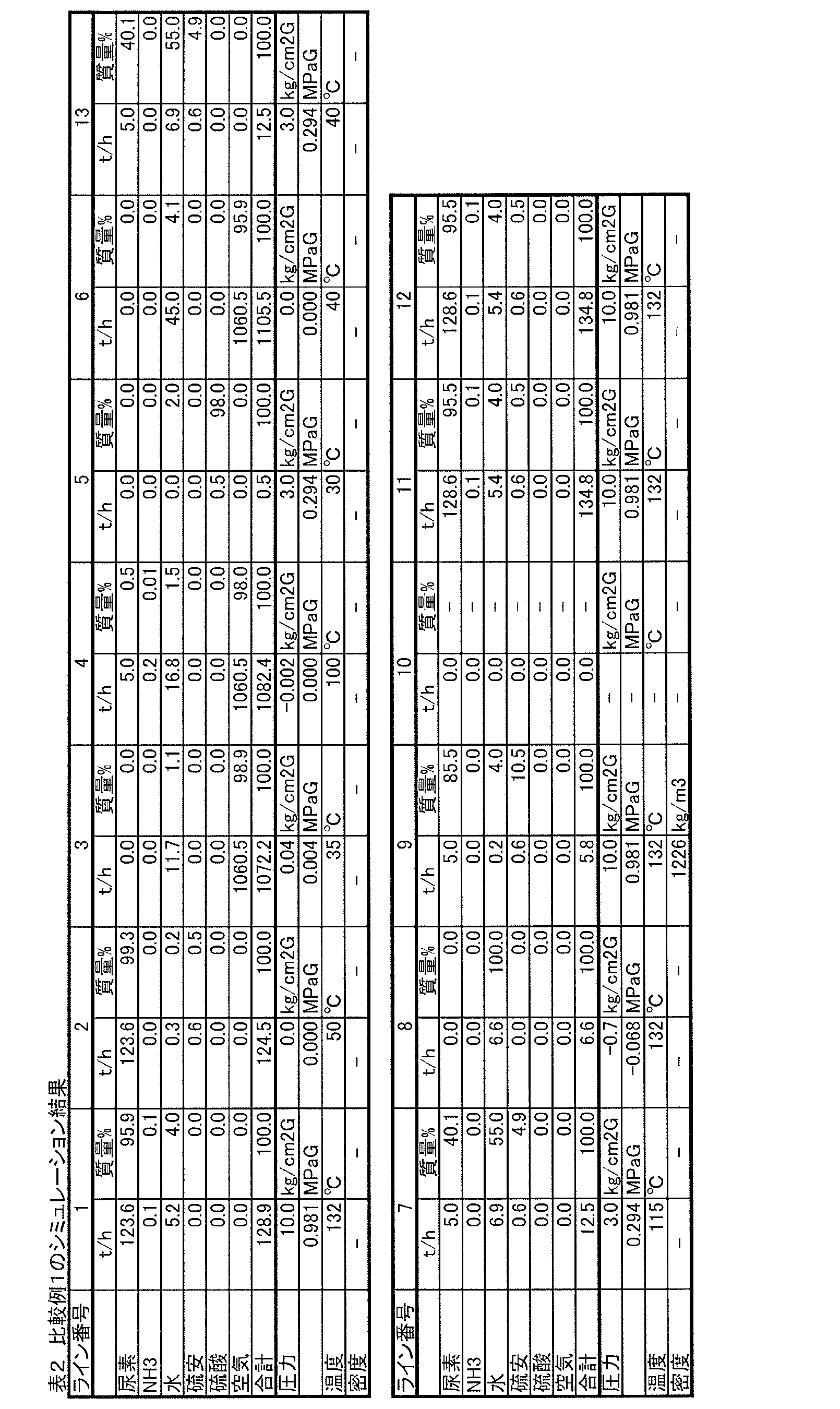
- Example 1 A process simulation was performed for the process flow shown in FIG. The results are shown in Table 1.
- Raw material aqueous urea solution (temperature: 132 ° C., pressure: 10.0 kg / cm 2 G (0.981 MPaG), flow rate: 128.9 t / h) (urea: 95.9 mass%, ammonia: 0.1 mass%, water 4.0 mass) %) was supplied from line 1.
- G in the pressure unit means a gauge pressure.
- the raw urea aqueous solution (line 1) originally contained 1000 ppm by mass (0.128 t / h) of free ammonia.
- granulation step A 0.03 t / h of free ammonia was generated by the biuret formation reaction.
- the granulation step A all of the ammonia (0.158 t / h) was moved to the air side and included in the gas in the line 4.
- a concentrated recovered urea aqueous solution (line 9) having a temperature of 132 ° C., a pressure of 10.0 kg / cm 2 G (0.981 MPaG), and a flow rate of 18.3 t / h was mixed with a raw urea aqueous solution (line 1).
- the obtained mixed liquid (line 11) is branched into a flow with a flow rate of 12.5 t / h (line 10) and a flow with a flow rate of 134.8 t / h (line 12), and the former is made into a low ammonium salt concentration urea aqueous solution. Used, the latter fed to granulation step A.
- water from line 8 was also supplied as make-up water in addition to make-up water containing sulfuric acid (line 5).
- concentrations of urea and ammonia in the exhaust gas discharged from the recovery step B to the line 6 were both 30 to 50 ppm by mass.
- urea and ammonia contained in the gas in the line 4 are recovered in the recovered urea aqueous solution (line 13). However, at this time, the ammonia in the gas reacts with the sulfuric acid supplied from the line 5 and is recovered as ammonium sulfate in the recovered urea aqueous solution.
- the recovered urea aqueous solution (line 13) and the low ammonium salt concentration urea aqueous solution (line 10) are mixed (ammonium salt concentration adjusting step), and the resulting mixed solution (urea aqueous solution whose ammonium salt concentration is adjusted) is concentrated from line 7. Supplied to the process.
- the ammonium sulfate concentration of the low ammonium salt concentration urea aqueous solution in line 10 is 0.5% by mass
- the ammonium sulfate concentration in the recovered urea aqueous solution in line 13 is 4.9% by mass
- the former is lower than the latter (approximately 1/10) is there).
- the temperature of the recovered urea aqueous solution (line 13) is 40 ° C.
- the temperature of the mixed solution (line 7) supplied to the concentration step C is 115 ° C. Since corrosion occurs when the temperature is high, when performing the step of neutralizing the acid in the urea aqueous solution supplied to the concentration step, it is preferable to neutralize while the temperature is lower, specifically 40 ° C recovery. It is preferable to add an alkali (for example, ammonia) to the urea aqueous solution (line 13).
- an alkali for example, ammonia
- the urea aqueous solution (line 7) in which the ammonium salt concentration was adjusted was heated to evaporate water to obtain a concentrated recovered urea aqueous solution (line 9) in which urea was concentrated.
- the flow rate of the low ammonium salt concentration urea aqueous solution (line 10) was determined so that the ammonium sulfate concentration in the line 9 was 3.7% by mass.
- Water vapor obtained by evaporating water (containing no urea, ammonium salt or acid) was supplied from line 8 to recovery step B.
- heating, cooling, pressurization, and decompression of the fluid are performed as necessary by appropriate means (heat exchanger, pump, blower, decompression valve, etc.).
- heat exchanger heat exchanger
- pump blower
- decompression valve etc.
- the recovered urea aqueous solution was heated by a heat exchanger before the recovered urea aqueous solution (line 13) and the low ammonium salt concentration urea aqueous solution (line 10) were mixed (the liquid temperature in line 7 was 115 ° C.). like).
- concentration step C water was evaporated using an evaporator that was made negative pressure by an ejector.
- the obtained concentrated and recovered urea aqueous solution was pressurized to 10.0 kg / cm 2 G (0.981 MPaG) by a pump and sent to the line 9.
- the granulator used in the granulation step A and the line 4 were also kept at a negative pressure, and the gas discharged from the recovery step B was pressurized with a blower and discharged to the line 6.
- the concentrated and recovered urea aqueous solution is composed of three components: urea, ammonium sulfate, and water.
- urea urea
- ammonium sulfate urea
- water concentration determined in a preliminary experiment.
- the water concentration at which the vapor pressure of water coincides with the pressure “ ⁇ 0.7 Kg / cm 2 G ( ⁇ 0.068 MPaG)” of the concentration step C was determined, it was 4% by mass. That is, the water concentration of the concentrated and recovered urea aqueous solution was 4% by mass.
- the density of the binary liquid mixture composed of 4% by mass of water and urea (96% by mass) and the density of ammonium sulfate (pure substance) can be estimated if the temperature is determined. And the density which estimated the mixing ratio of the said 2 component liquid mixture and ammonium sulfate in the case where the liquid of the same composition as the concentration collection
- the density (measured value) of the concentrated and recovered urea aqueous solution is 1204.8 kg / m 3 and the temperature is 132 ° C.
- the density of the binary mixture is 1193.6 kg / m 3
- the density of ammonium sulfate is 1499.6 kg / m 3 .
- the correlation between the water concentration, density, and temperature of the binary mixture and the correlation between the density and temperature of ammonium sulfate were determined by preliminary experiments.
- Example 1 A process simulation was performed in the same manner as in Example 1 except that the flow rate of the flow of the line 10 was set to zero. That is, the recovered urea aqueous solution obtained from the recovery step was supplied to the concentration step without adjusting its ammonium salt concentration.
- Example 1 the concentration of ammonium sulfate in the concentrated and recovered urea aqueous solution (line 9) was 3.7% by mass. In Example 1, ammonium sulfate precipitation can be prevented.
- the ammonium salt concentration in the urea aqueous solution is decreased by mixing the recovered aqueous urea solution with the low ammonium salt concentration urea aqueous solution before the concentration step. Let Then, water is removed in the concentration step. Thereby, precipitation of ammonium salt can be prevented.
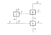
- a Granulation step B Recovery step C Concentration step 1 Raw material urea aqueous solution 2 Granular solid urea 3 Air 4 Granulation outlet gas (air containing urea dust and ammonia) 5 makeup water (including acid) 6 Exhaust gas 7 Recovered urea aqueous solution (supplied to the concentration process) 8 Water resulting from the concentration process 9 Concentrated recovered urea aqueous solution (including ammonium salt) 10 Low ammonium salt concentration urea aqueous solution 11 Raw material urea aqueous solution 12 mixed with concentrated and recovered urea aqueous solution 12 Remaining liquid from which the liquid in line 10 is branched from the liquid in line 11 13 Recovered urea aqueous solution (obtained from the recovery process) 15 Part of the raw urea aqueous solution (sent to the granulation process) 16 The remainder of the raw urea aqueous solution (low ammonium salt concentration urea aqueous solution)
Landscapes
- Chemical & Material Sciences (AREA)
- Organic Chemistry (AREA)
- Chemical Kinetics & Catalysis (AREA)
- Organic Low-Molecular-Weight Compounds And Preparation Thereof (AREA)
- Fertilizers (AREA)
Abstract
Description
原料尿素水溶液から空気を用いて粒状の固体尿素を製造する造粒工程、
造粒工程から排出される尿素ダストおよびアンモニアを含む空気から、尿素ダストおよびアンモニアを、酸を含む水溶液を用いて回収することにより、尿素およびアンモニウム塩を含む水溶液である回収尿素水溶液を得る回収工程、
回収工程から得られた回収尿素水溶液に、この回収尿素水溶液と比べてアンモニウム塩濃度が相対的に低い尿素水溶液を混合することにより、回収尿素水溶液中のアンモニウム塩濃度を調整するアンモニウム塩濃度調整工程、
アンモニウム塩濃度調整工程から得られた回収尿素水溶液に含まれる水を蒸発させることにより、アンモニウム塩濃度調整工程から得られた回収尿素水溶液を濃縮して、濃縮回収尿素水溶液を得る濃縮工程、および、
原料尿素水溶液に前記濃縮回収尿素水溶液を混合する混合工程
を含み、
前記濃縮回収尿素水溶液のアンモニウム塩濃度を7質量%以下にする
尿素の造粒方法が提供される。
図1に示すように、ライン1から供給された原料尿素水溶液が、造粒工程Aに送られる。造粒工程Aでは、空気を用いて、原料尿素水溶液から粒状の固体尿素を製造する。ただし、原料尿素水溶液(ライン1)に濃縮回収尿素水溶液(ライン9)を混合するので、造粒工程Aにおいて、原料尿素水溶液から粒状固体尿素が製造されるとともに、濃縮回収尿素水溶液からも粒状固体尿素が製造される。なお、図1に示すプロセスにおいては、原料尿素水溶液と濃縮回収尿素水溶液とを混合した液(ライン11)が分岐され、その一部(ライン12)が造粒工程Aに供給され、残部(ライン10)がアンモニウム塩濃度調整工程において回収尿素水溶液(ライン13)に混合される。したがって、ライン12から造粒工程Aに導入された尿素水溶液中の尿素が、ライン3から供給される空気により凝固および冷却されて固体尿素となり、ライン2から製品として取り出される。
回収工程Bでは、造粒出口ガス(ライン4)から、尿素ダストおよびアンモニアを、酸を含む水溶液を用いて回収することにより、回収尿素水溶液(ライン13)を得る。
回収工程から得られた回収尿素水溶液(ライン13)に、この回収尿素水溶液と比べてアンモニウム塩濃度が相対的に低い尿素水溶液(以下、「低アンモニウム塩濃度尿素水溶液」と呼ぶことがある)を混合することにより、回収尿素水溶液中のアンモニウム塩濃度を調整する。つまり、回収尿素水溶液(ライン13)よりもアンモニウム塩濃度が低い尿素水溶液(ライン10)を、回収尿素水溶液(ライン13)に加え、アンモニウム塩濃度が低下した回収尿素水溶液(ライン7)を得る。低アンモニウム塩濃度尿素水溶液の混合量は、濃縮回収尿素水溶液(ライン9)中のアンモニウム塩濃度が7質量%以下になるように、決める。
濃縮工程では、アンモニウム塩濃度調整工程から得られた回収尿素水溶液(ライン7)に含まれる水を蒸発させることにより、この回収尿素水溶液を濃縮して、濃縮回収尿素水溶液(ライン9)を得る。
濃縮工程Cで濃縮した濃縮回収尿素水溶液(ライン9)を、ライン1から供給される原料尿素水溶液と混合する。図1に示すプロセスでは、原料尿素水溶液(ライン1)の全部と濃縮回収尿素水溶液(ライン9)とが混合され、得られる混合液(ライン11)の一部(ライン12)が造粒工程Aに供給される。図3に示すプロセスでは、原料尿素水溶液の一部(ライン15)と濃縮回収尿素水溶液(ライン9)とが混合され、得られる混合液(11)の全部が造粒工程Aに供給される。
必要に応じ、回収工程Bから得られた回収尿素水溶液(ライン13)にアルカリを加えることにより、回収尿素水溶液を中和することができる。
濃縮回収尿素水溶液(ライン9)のアンモニウム塩濃度の現在値(PV)に基づいて、アンモニウム塩濃度調整工程において回収尿素水溶液(ライン13)に混合する低アンモニウム塩濃度尿素水溶液(図1のライン10、図3のライン16)の流量を操作することにより、濃縮回収尿素水溶液(ライン9)のアンモニウム塩濃度を目標値(SV)に制御することができる。
回収尿素水溶液(ライン7)や濃縮回収尿素水溶液(ライン9)のような、実質的に尿素、アンモニウム塩および水からなる3成分尿素水溶液の水の蒸気圧は、3成分尿素水溶液の温度と水濃度によって決まる。温度と圧力が一定であれば、水の分圧が蒸気圧と同じになるまで3成分尿素水溶液中の水分は蒸発し、したがって3成分尿素水溶液の濃縮が進む。このとき、3成分尿素水溶液から蒸発する物のほとんどは水なので(無視可能な量のアンモニアや二酸化炭素も蒸発するが)、水の分圧と運転圧力とが等しいと見なすことができる。したがって、濃縮工程における水蒸発の温度・圧力が決まると、濃縮回収尿素水溶液中の水の濃度を推算することができる。このとき、3成分尿素水溶液の温度と、水の蒸気圧と、水分濃度との間の相関を用いることができる。この相関は予備実験によって求めることができる。
上記のようにして濃縮回収尿素水溶液の水濃度が分かるため、濃縮回収尿素水溶液の残りの成分の濃度(尿素とアンモニウム塩の合計濃度)が分かる。また、アンモニウム塩と尿素の密度は異なる。したがって、濃縮回収尿素水溶液の密度が分かれば、尿素とアンモニウム塩の比率が推算できる。また、温度による密度への影響を補正するため、温度を密度と一緒に測定することができる。尿素とアンモニウム塩の比率を推算するために、尿素と水とからなる2成分混合液の水濃度と密度と温度との相関、および硫酸アンモニウムの密度と温度との相関、を用いることができる。これらの相関は予備実験によって求めることができる。
図1に示すプロセスフローにつき、プロセスシミュレーションを行った。その結果を表1に示す。
1193.6×(1-c)+1499.6×c=1204.8
すなわち、濃縮回収尿素水溶液において、水の濃度は4質量%であり、硫酸アンモニウムの濃度は3.7質量%であることが求まった。したがって、尿素濃度は92.3質量%である。
ライン10の流れの流量をゼロとしたこと以外は実施例1と同様にプロセスシミュレーションを行った。すなわち、回収工程から得られた回収尿素水溶液を、そのアンモニウム塩濃度を調整することなく、濃縮工程に供給した。

B 回収工程
C 濃縮工程
1 原料尿素水溶液
2 粒状固体尿素
3 空気
4 造粒出口ガス(尿素ダストおよびアンモニアを含む空気)
5 補給水(酸を含む)
6 排ガス
7 回収尿素水溶液(濃縮工程に供給される)
8 濃縮工程から生じる水
9 濃縮回収尿素水溶液(アンモニウム塩を含む)
10 低アンモニウム塩濃度尿素水溶液
11 濃縮回収尿素水溶液が混合された原料尿素水溶液
12 ライン11の液からライン10の液が分岐された残りの液
13 回収尿素水溶液(回収工程から得られる)
15 原料尿素水溶液の一部(造粒工程に送られる)
16 原料尿素水溶液の残部(低アンモニウム塩濃度尿素水溶液)
Claims (7)
- 原料尿素水溶液から空気を用いて粒状の固体尿素を製造する造粒工程、
造粒工程から排出される尿素ダストおよびアンモニアを含む空気から、尿素ダストおよびアンモニアを、酸を含む水溶液を用いて回収することにより、尿素およびアンモニウム塩を含む水溶液である回収尿素水溶液を得る回収工程、
回収工程から得られた回収尿素水溶液に、この回収尿素水溶液と比べてアンモニウム塩濃度が相対的に低い尿素水溶液を混合することにより、回収尿素水溶液中のアンモニウム塩濃度を調整するアンモニウム塩濃度調整工程、
アンモニウム塩濃度調整工程から得られた回収尿素水溶液に含まれる水を蒸発させることにより、アンモニウム塩濃度調整工程から得られた回収尿素水溶液を濃縮して、濃縮回収尿素水溶液を得る濃縮工程、および、
原料尿素水溶液に前記濃縮回収尿素水溶液を混合する混合工程
を含み、
前記濃縮回収尿素水溶液のアンモニウム塩濃度を7質量%以下にする
尿素の造粒方法。 - 濃縮回収尿素水溶液が混合される前の原料尿素水溶液の一部、あるいは、濃縮回収尿素水溶液が混合された後の原料尿素水溶液の一部を、アンモニウム塩濃度調整工程において前記アンモニウム塩濃度が相対的に低い尿素水溶液として用いる、請求項1に記載の方法。
- 回収工程から得られた回収尿素水溶液にアルカリを加えることにより、回収尿素水溶液を中和する中和工程を、濃縮工程の前に有する、請求項1または2に記載の方法。
- 前記濃縮回収尿素水溶液のアンモニウム塩濃度の現在値に基づいて、アンモニウム塩濃度調整工程において回収尿素水溶液に混合する前記アンモニウム塩濃度が相対的に低い尿素水溶液の流量を操作することにより、前記濃縮回収尿素水溶液のアンモニウム塩濃度を制御する制御工程を有する、請求項1~3の何れか一項に記載の方法。
- 前記制御工程において、濃縮工程における水蒸発の温度および圧力と、前記濃縮回収尿素水溶液の温度および密度とに基づいて、前記濃縮回収尿素水溶液のアンモニウム塩濃度の現在値を求める、請求項4に記載の方法。
- 前記酸が、硫酸、硝酸およびリン酸から選ばれる少なくとも一種の酸である、請求項1~5の何れか一項に記載の方法。
- 濃縮工程で蒸発させた水を、回収工程に供給する工程を含む、請求項1~6の何れか一項に記載の方法。
Priority Applications (6)
| Application Number | Priority Date | Filing Date | Title |
|---|---|---|---|
| EP18767920.4A EP3597633B1 (en) | 2017-03-17 | 2018-03-06 | Method for granulating urea |
| BR112019018446-5A BR112019018446B1 (pt) | 2017-03-17 | 2018-03-06 | Método para granulação contínua de ureia |
| CA3055063A CA3055063C (en) | 2017-03-17 | 2018-03-06 | Method for granulating urea |
| US16/494,710 US10894764B2 (en) | 2017-03-17 | 2018-03-06 | Method for granulating urea |
| CN201880018045.8A CN110418782B (zh) | 2017-03-17 | 2018-03-06 | 尿素的造粒方法 |
| EA201992037A EA038039B1 (ru) | 2017-03-17 | 2018-03-06 | Способ гранулирования мочевины |
Applications Claiming Priority (2)
| Application Number | Priority Date | Filing Date | Title |
|---|---|---|---|
| JP2017052199A JP6851869B2 (ja) | 2017-03-17 | 2017-03-17 | 尿素の造粒方法 |
| JP2017-052199 | 2017-03-17 |
Publications (1)
| Publication Number | Publication Date |
|---|---|
| WO2018168573A1 true WO2018168573A1 (ja) | 2018-09-20 |
Family
ID=63523744
Family Applications (1)
| Application Number | Title | Priority Date | Filing Date |
|---|---|---|---|
| PCT/JP2018/008574 Ceased WO2018168573A1 (ja) | 2017-03-17 | 2018-03-06 | 尿素の造粒方法 |
Country Status (8)
| Country | Link |
|---|---|
| US (1) | US10894764B2 (ja) |
| EP (1) | EP3597633B1 (ja) |
| JP (1) | JP6851869B2 (ja) |
| CN (1) | CN110418782B (ja) |
| BR (1) | BR112019018446B1 (ja) |
| CA (1) | CA3055063C (ja) |
| EA (1) | EA038039B1 (ja) |
| WO (1) | WO2018168573A1 (ja) |
Cited By (1)
| Publication number | Priority date | Publication date | Assignee | Title |
|---|---|---|---|---|
| JP2022526860A (ja) * | 2019-05-22 | 2022-05-26 | スタミカーボン・ベー・フェー | 尿素仕上げからのオフガスの処理 |
Families Citing this family (4)
| Publication number | Priority date | Publication date | Assignee | Title |
|---|---|---|---|---|
| DE102021202869A1 (de) * | 2021-03-24 | 2022-09-29 | Thyssenkrupp Ag | Anlage und Verfahren zur Herstellung von Harnstoffgranulat |
| CN113426267B (zh) * | 2021-08-02 | 2025-09-23 | 河北正元化工工程设计有限公司 | 一种尿素尾气游离氨回收装置 |
| WO2025146796A1 (ja) * | 2024-01-05 | 2025-07-10 | 東洋エンジニアリング株式会社 | 尿素製造装置、尿素製造装置の改良方法および尿素製造方法 |
| WO2025244534A1 (en) * | 2024-05-23 | 2025-11-27 | Stamicarbon B.V. | Technical grade urea granulate |
Citations (5)
| Publication number | Priority date | Publication date | Assignee | Title |
|---|---|---|---|---|
| JPH09227493A (ja) * | 1996-02-27 | 1997-09-02 | Toyo Eng Corp | 排ガス中からの尿素ダスト及びアンモニアの回収方法 |
| JP2000001466A (ja) | 1998-06-12 | 2000-01-07 | Toyo Eng Corp | 排ガス中の尿素ダスト及びアンモニアの回収・利用方法 |
| US20110229394A1 (en) | 2008-11-28 | 2011-09-22 | Uhde Fertilizer Techology B.V. | Urea granulation process with an acidic scrubbing system and the subsequent integration of ammonium salt into urea granules |
| JP2015520741A (ja) * | 2012-05-03 | 2015-07-23 | スタミカーボン・ベー・フェー | 尿素製造プラント |
| WO2016159336A1 (ja) * | 2015-04-01 | 2016-10-06 | 東洋エンジニアリング株式会社 | 尿素製造方法 |
Family Cites Families (4)
| Publication number | Priority date | Publication date | Assignee | Title |
|---|---|---|---|---|
| JP4640837B2 (ja) * | 2006-06-22 | 2011-03-02 | 京セラミタ株式会社 | 用紙収納装置及びそれを備えた画像形成装置 |
| EP2301917A1 (en) * | 2009-09-16 | 2011-03-30 | Stamicarbon B.V. | Removal of urea and ammonia from exhaust gases |
| EP2662349A1 (en) * | 2012-05-08 | 2013-11-13 | Uhde Fertilizer Technology B.V. | Urea granulation process with scrubbing system |
| EP3020702A1 (en) * | 2014-11-12 | 2016-05-18 | Casale SA | Urea finishing process with acid scrubbing |
-
2017
- 2017-03-17 JP JP2017052199A patent/JP6851869B2/ja active Active
-
2018
- 2018-03-06 EA EA201992037A patent/EA038039B1/ru unknown
- 2018-03-06 EP EP18767920.4A patent/EP3597633B1/en active Active
- 2018-03-06 US US16/494,710 patent/US10894764B2/en active Active
- 2018-03-06 WO PCT/JP2018/008574 patent/WO2018168573A1/ja not_active Ceased
- 2018-03-06 BR BR112019018446-5A patent/BR112019018446B1/pt active IP Right Grant
- 2018-03-06 CA CA3055063A patent/CA3055063C/en active Active
- 2018-03-06 CN CN201880018045.8A patent/CN110418782B/zh active Active
Patent Citations (6)
| Publication number | Priority date | Publication date | Assignee | Title |
|---|---|---|---|---|
| JPH09227493A (ja) * | 1996-02-27 | 1997-09-02 | Toyo Eng Corp | 排ガス中からの尿素ダスト及びアンモニアの回収方法 |
| JP2000001466A (ja) | 1998-06-12 | 2000-01-07 | Toyo Eng Corp | 排ガス中の尿素ダスト及びアンモニアの回収・利用方法 |
| US20110229394A1 (en) | 2008-11-28 | 2011-09-22 | Uhde Fertilizer Techology B.V. | Urea granulation process with an acidic scrubbing system and the subsequent integration of ammonium salt into urea granules |
| JP2012509833A (ja) * | 2008-11-28 | 2012-04-26 | ウーデ・フェルティリツァー・テヒノロギー・ベスローテン・フェンノートシャップ | 酸性スクラビングシステムによる尿素造粒法及びその後のアンモニウム塩の尿素顆粒中への組み入れ |
| JP2015520741A (ja) * | 2012-05-03 | 2015-07-23 | スタミカーボン・ベー・フェー | 尿素製造プラント |
| WO2016159336A1 (ja) * | 2015-04-01 | 2016-10-06 | 東洋エンジニアリング株式会社 | 尿素製造方法 |
Non-Patent Citations (1)
| Title |
|---|
| See also references of EP3597633A4 |
Cited By (2)
| Publication number | Priority date | Publication date | Assignee | Title |
|---|---|---|---|---|
| JP2022526860A (ja) * | 2019-05-22 | 2022-05-26 | スタミカーボン・ベー・フェー | 尿素仕上げからのオフガスの処理 |
| JP7197732B2 (ja) | 2019-05-22 | 2022-12-27 | スタミカーボン・ベー・フェー | 尿素仕上げからのオフガスの処理 |
Also Published As
| Publication number | Publication date |
|---|---|
| EP3597633A4 (en) | 2020-12-23 |
| BR112019018446A2 (pt) | 2020-04-14 |
| CN110418782A (zh) | 2019-11-05 |
| US10894764B2 (en) | 2021-01-19 |
| EA201992037A1 (ru) | 2020-02-17 |
| CA3055063C (en) | 2024-07-02 |
| CN110418782B (zh) | 2022-05-10 |
| EP3597633B1 (en) | 2022-05-04 |
| US20200002274A1 (en) | 2020-01-02 |
| JP2018154582A (ja) | 2018-10-04 |
| EA038039B1 (ru) | 2021-06-28 |
| BR112019018446B1 (pt) | 2023-02-14 |
| JP6851869B2 (ja) | 2021-03-31 |
| CA3055063A1 (en) | 2018-09-20 |
| EP3597633A1 (en) | 2020-01-22 |
Similar Documents
| Publication | Publication Date | Title |
|---|---|---|
| WO2018168573A1 (ja) | 尿素の造粒方法 | |
| JP7277672B2 (ja) | 尿素仕上げからのアンモニア除去 | |
| US10954186B2 (en) | Urea ammonium nitrate production comprising condensation | |
| JP6415544B2 (ja) | 尿素プラントのガス流から硫酸アンモニウムを回収する方法およびシステム | |
| JP2018052986A (ja) | 尿素製造プラント | |
| CN114901373B (zh) | 使用多个蒸发器的尿素生产 | |
| JP7085020B2 (ja) | 尿素生成プラントおよびスクラビングシステム | |
| CN107848903B (zh) | 尿素产品的制粒 | |
| EP3233244B1 (en) | Removal of dust in urea finishing | |
| US20200002239A1 (en) | Urea ammonium nitrate production | |
| US3690820A (en) | Production of ammonium nitrate | |
| US20250178913A1 (en) | System and processs for the production of uan | |
| EA043041B1 (ru) | Удаление аммиака из доводочной секции карбамида | |
| EA020676B1 (ru) | Способ получения гранулированного аммофоса |
Legal Events
| Date | Code | Title | Description |
|---|---|---|---|
| 121 | Ep: the epo has been informed by wipo that ep was designated in this application |
Ref document number: 18767920 Country of ref document: EP Kind code of ref document: A1 |
|
| ENP | Entry into the national phase |
Ref document number: 3055063 Country of ref document: CA |
|
| REG | Reference to national code |
Ref country code: BR Ref legal event code: B01A Ref document number: 112019018446 Country of ref document: BR |
|
| NENP | Non-entry into the national phase |
Ref country code: DE |
|
| WWE | Wipo information: entry into national phase |
Ref document number: 2018767920 Country of ref document: EP |
|
| ENP | Entry into the national phase |
Ref document number: 2018767920 Country of ref document: EP Effective date: 20191017 |
|
| ENP | Entry into the national phase |
Ref document number: 112019018446 Country of ref document: BR Kind code of ref document: A2 Effective date: 20190905 |