WO2018168614A1 - ロックリング及び管継手 - Google Patents
ロックリング及び管継手 Download PDFInfo
- Publication number
- WO2018168614A1 WO2018168614A1 PCT/JP2018/008845 JP2018008845W WO2018168614A1 WO 2018168614 A1 WO2018168614 A1 WO 2018168614A1 JP 2018008845 W JP2018008845 W JP 2018008845W WO 2018168614 A1 WO2018168614 A1 WO 2018168614A1
- Authority
- WO
- WIPO (PCT)
- Prior art keywords
- claw
- lock ring
- pipe joint
- axial direction
- pipe
- Prior art date
- Legal status (The legal status is an assumption and is not a legal conclusion. Google has not performed a legal analysis and makes no representation as to the accuracy of the status listed.)
- Ceased
Links
Images


Classifications
-
- F—MECHANICAL ENGINEERING; LIGHTING; HEATING; WEAPONS; BLASTING
- F16—ENGINEERING ELEMENTS AND UNITS; GENERAL MEASURES FOR PRODUCING AND MAINTAINING EFFECTIVE FUNCTIONING OF MACHINES OR INSTALLATIONS; THERMAL INSULATION IN GENERAL
- F16L—PIPES; JOINTS OR FITTINGS FOR PIPES; SUPPORTS FOR PIPES, CABLES OR PROTECTIVE TUBING; MEANS FOR THERMAL INSULATION IN GENERAL
- F16L37/00—Couplings of the quick-acting type
- F16L37/08—Couplings of the quick-acting type in which the connection between abutting or axially overlapping ends is maintained by locking members
- F16L37/084—Couplings of the quick-acting type in which the connection between abutting or axially overlapping ends is maintained by locking members combined with automatic locking
- F16L37/091—Couplings of the quick-acting type in which the connection between abutting or axially overlapping ends is maintained by locking members combined with automatic locking by means of a ring provided with teeth or fingers
Definitions
- the present invention relates to a lock ring for preventing a pipe inserted into a pipe joint from coming out of the pipe joint, and a pipe joint.
- a lock ring for preventing a pipe body inserted into a pipe joint from coming out of the pipe joint
- a plurality of structures configured to bite into the pipe body inserted into the pipe joint from the outer peripheral side.
- claw part is what is each flat plate shape (for example, patent document 1).
- the present invention is for solving the above-described problems, and includes a lock ring that can suppress excessive biting into a pipe inserted into a pipe joint, and a lock ring to a pipe inserted into the pipe joint.
- An object of the present invention is to provide a pipe joint that can suppress excessive biting.
- the lock ring of the present invention is a lock ring for preventing a pipe body inserted into a pipe joint from coming out of the pipe joint, and is arranged along an annular ring portion and a circumferential direction of the ring portion.
- Each having a plurality of plate-like claw portions extending from the ring portion in an extending direction toward the inner circumferential side and one axial direction of the ring portion, and the plurality of claw portions are at least a part thereof.
- a wave shape is formed in the cross section perpendicular to the axial direction.
- the pipe joint of the present invention includes a pipe joint main body that partitions an insertion space into which the pipe body is inserted, the lock ring that is disposed on the outer peripheral side of the insertion space, and the outer peripheral side of the insertion space or A sealing member that is disposed on the inner peripheral side and seals fluid tightly between the pipe joint body and the pipe body in a state where the pipe body is inserted into the insertion space. .
- a lock ring that can suppress excessive biting into the pipe inserted into the pipe joint, and a pipe joint that can suppress excessive biting of the lock ring into the pipe inserted into the pipe joint, Can be provided.
- FIG. 4 is a perspective view showing the lock ring of FIG. 3 with a part cut away.
- FIG. 4 is a partial cross-sectional perspective view showing a part of the lock ring of FIG. 3 together with a cross section taken along line AA of FIG. 3.
- FIG. 5 is a perspective view showing a part of the lock ring in FIG. 3 as viewed from an arrow B in FIG. 4. It is a figure for demonstrating the result of the analysis performed about the lock ring.
- FIG. 9 is a partial cross-sectional perspective view showing a part of the lock ring of FIG. 8 together with a cross section taken along the line A′-A ′ of FIG. 8.
- FIG. 10 is a perspective view showing a part of the lock ring in FIG. 8 as viewed from an arrow B ′ in FIG. 9.
- FIG. 12A is a plan view showing a part of a second modification of the lock ring of the present invention
- FIG. 12B is a perspective view showing a part of the lock ring shown in FIG. is there.
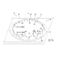
- FIG. 1 is a perspective view of the pipe joint 1 of the present embodiment
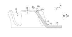
- FIG. 2 is a partial cross-sectional side view showing a part of the pipe joint 1 of FIG. 1 together with a cross section along the axial direction of the pipe joint 1.
- the axial direction of the pipe joint 1 (hereinafter sometimes simply referred to as “axial direction”) means a direction along the central axis of the pipe joint 1.
- the center axis of the pipe joint 1 coincides with a center axis O of a lock ring 30 described later.
- a total of two insertion spaces 20 are formed, one in each of the left and right sides in FIG. Has been.
- the tube body 2 is shown inserted into only the left insertion space 20.
- the pipe body 2 inserted into the pipe joint 1 is, for example, a pipe for water supply / hot water supply made of polybutene or cross-linked polyethylene.
- the pipe joint 1 may have only one insertion space 20 or three or more insertion spaces 20.
- the pipe joint 1 of the present embodiment includes a pipe joint main body 10, a lock ring 30 according to an embodiment of the present invention, and a sealing member 40.
- the pipe joint body 10 defines the insertion spaces 20 on both sides in the axial direction.
- the pipe joint main body 10 includes an outer cylinder member 11, an inner cylinder member 12, a fitting member 13, and an intermediate spacer member 14.
- the outer cylinder member 11 is made of, for example, resin or metal, and has a substantially cylindrical shape extending over the entire length in the axial direction of the pipe joint 1 in the illustrated example. As shown in FIG. 2, on the inner peripheral surface of the outer cylinder member 11, a step portion 11 a that protrudes toward the inner peripheral side is provided at substantially the center in the axial direction of the pipe joint 1.
- one inner space member 12, fitted member 13, intermediate spacer member 14, lock ring 30, and sealing member 40 are provided for each insertion space 20.
- the direction pointing to the left side in FIG. 2 is referred to as “axial direction first side” and the direction pointing to the right side in FIG. 2 is referred to as “axial direction second side”.
- the inner cylinder member 12, the fitted member 13, the intermediate spacer member 14, the lock ring 30, and the inner ring member 12 provided corresponding to the insertion space 20 on the second axial side (the right side in FIG. 2)
- the configuration of the sealing member 40 will be described.
- the inner cylinder member 12, the fitting member 13, the intermediate spacer member 14, the lock ring 30, and the sealing member 40 provided corresponding to the insertion space 20 on the first axial side (left side in FIG. 2).
- the configuration is the same.
- the direction toward the first axial direction is the direction in which the tubular body 2 is inserted into the insertion space 20 (hereinafter referred to as “insertion direction ID”).
- the direction toward the second side in the axial direction is the direction in which the tubular body 2 is extracted from the insertion space 20 (hereinafter referred to as “extraction direction PD”).
- the inner cylinder member 12 is made of, for example, resin or metal, and is inserted on the inner peripheral side of the outer cylinder member 11.
- the inner cylinder member 12 is a small-diameter pipe portion 12a that is spaced inward from the outer cylinder member 11, and a large-diameter pipe that is positioned on the outer peripheral side of the small-diameter pipe portion 12a and that contacts the inner peripheral surface of the outer cylinder member 11.
- a connecting portion 12c that connects the small-diameter pipe portion 12a and the large-diameter pipe portion 12b and contacts the stepped portion 11a of the outer cylinder member 11.
- the inner peripheral surface of the small-diameter pipe portion 12 a defines the flow path of the pipe joint 1.
- the outer peripheral surface of the small-diameter tube portion 12a, the inner peripheral surface of the large-diameter tube portion 12b, and the surface facing the second axial side of the connecting portion 12c (the inlet side of the insertion space 20) are the ones of the insertion space 20.
- the section is divided.
- the intermediate spacer member 14 is made of, for example, resin, and is axial in the inner peripheral side of the outer cylindrical member 11, the outer peripheral side of the small-diameter pipe portion 12 a of the inner cylindrical member 12, and the large-diameter pipe portion 12 b of the inner cylindrical member 12. It arrange
- the fitting member 13 is made of, for example, resin, and is disposed on the outer peripheral side of the small-diameter pipe portion 12a of the inner cylinder member 12 and on the second axial side (the inlet side of the insertion space 20) with respect to the intermediate spacer member 14.
- the outer cylinder member 11 is fitted into the inner peripheral surface.
- the inner peripheral surfaces of the intermediate spacer member 14 and the fitted member 13 define a part of the insertion space 20.
- the sealing member 40 is made of, for example, an elastic O-ring.
- the sealing member 40 is on the outer peripheral side of the insertion space 20 and between the large-diameter pipe portion 12b of the inner cylindrical member 12 and the intermediate spacer member 14 in the axial direction. And provided over the entire circumference.
- the inner diameter of the sealing member 40 is the inner diameter of the large-diameter pipe portion 12 b of the inner cylinder member 12, the inner diameter of the intermediate spacer member 14, and the fitted member 13. It is slightly smaller than any of the inner diameters.
- the lock ring 30 of the present embodiment is made of, for example, metal, and is disposed on the outer peripheral side of the insertion space 20 and between the intermediate spacer member 14 and the fitting member 13 in the axial direction.
- the lock ring 30 is arranged along the circumferential direction of the annular plate-like ring portion 31 and the ring portion 31 that are continuous over the entire circumference on the outer peripheral side of the insertion space 20, and each ring. From the inner peripheral side end of the portion 31 to the inner peripheral side of the ring portion 31 and the back side in the insertion direction of the insertion space 20 (on the side opposite to the inlet of the insertion space 20. One side in the axial direction of the ring portion 31).
- the inner diameter of the claw portion 32 of the lock ring 30 is the inner diameter of the large-diameter tube portion 12 b of the inner cylinder member 12, the inner diameter of the intermediate spacer member 14, and the fitting. It is slightly smaller than any of the inner diameters of the members 13.
- the tip end portion (end portion on the inner peripheral side) of the claw portion 32 of the lock ring 30 bites into the outer peripheral surface of the tube body 2 and is locked.
- the claw portion 32 of the lock ring 30 is in the second axial direction (inlet side of the insertion space 20). It functions to further bite into the outer peripheral surface of the tubular body 2 while bending to prevent the tubular body 2 from coming out of the insertion space 20.
- the pipe joint 1 of this embodiment is not restricted to what was mentioned above, Various modifications are possible.
- the sealing member 40 may be disposed on the second axial side (the inlet side of the insertion space 20) from the lock ring 30.
- the sealing member 40 may be accommodated in, for example, an annular groove (not shown) extending in the circumferential direction on the inner peripheral surface of the fitting member 13.
- the sealing member 40 is accommodated in, for example, an annular groove (not shown) extending in the circumferential direction on the outer peripheral surface of the small-diameter pipe portion 12a of the inner cylinder member 12, and the inner periphery of the insertion space 20 It may be arranged on the side.
- the sealing member 40 is deformed so as to be in close contact with the inner peripheral surface of the tubular body 2, whereby the tubular joint body 10, the tubular body 2, and the like. The fluid between is tightly sealed.
- the ring portion 31 of the lock ring 30 extends annularly along a virtual plane perpendicular to the axial direction of the pipe joint 1. You may extend cyclically
- FIGS. 3 to 6 is the same as the lock ring 30 provided in the pipe joint 1 shown in FIGS.
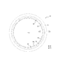
- FIG. 3 is a plan view showing the lock ring 30.
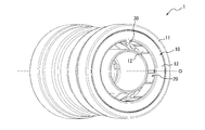
- FIG. 4 is a perspective view showing the lock ring 30 with a part cut away.
- FIG. 5 is a partial cross-sectional perspective view showing a part of the lock ring 30 together with a cross section taken along line AA of FIG.
- a line AA in FIG. 3 is along the radial direction of the ring portion 31 of the lock ring 30.
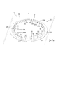
- FIG. 6 is a perspective view showing a part of the lock ring 30 as viewed from the arrow B in FIG. 4, and more specifically, a part of the lock ring 30 is a claw portion 32 of the lock ring 30. It shows how it was seen from the tip side.
- the lock ring 30 of the present embodiment is arranged along the circumferential direction of the ring portion 31 and the ring portion 31 (in this example, plate-like), and the inner peripheral side end of the ring portion 31 respectively.
- a plurality of (16 in the illustrated example) plate-like claw portions 32 extending from the portion (that is, the radially inner end portion) toward the inner peripheral side of the ring portion 31 and the one axial direction side of the ring portion 31.
- a slit 33 is formed between the claw portions 32.
- the axial direction of the ring portion 31 (hereinafter sometimes simply referred to as “axial direction”) means a direction along the central axis O of the lock ring 30 (same as the central axis of the ring portion 31).
- the claw portion 32 is moved from the ring portion 31 to the inner peripheral side of the ring portion 31 and the insertion space 20. It is oriented so as to extend toward the back side in the insertion direction.
- the lock ring 30 is formed by performing press processing, slit formation, bending formation, or the like on a single metal plate, that is, the ring portion 31 and the claw portion 32 are integrally formed.
- the ring part 31 and the claw part 32 may be formed separately from each other and fixed to each other.
- the material of the ring part 31 and the claw part 32 may be different, for example, the ring part 31 is made of resin and the claw part 32 is made of metal.
- the claw portion 32 may extend from a radially intermediate portion of the ring portion 31.
- FIG. 4 shows cross sections of the claw portions 32 along the virtual planes S1 and S2 perpendicular to the axial direction at two different axial positions for some of the claw portions 32, respectively.
- the plurality of claw portions 32 have a wave shape in a cross section perpendicular to the axial direction at least at a part thereof. More specifically, the plurality of claw portions 32 are at least a part of the extending direction toward the inner peripheral side and one axial direction (hereinafter also simply referred to as “extending direction ED of the claw portion 32”), and In addition, at least a part of the circumferential direction has a wave shape in a cross section perpendicular to the axial direction.
- the plurality of claw portions 32 are extended from the root portion (end portion on the ring portion 31 side of the claw portion 32) 321 in the extending direction ED of the claw portion 32.
- a wave shape is formed over the entire circumference.
- “having a wave shape in the cross section perpendicular to the axial direction” means that the cross section of the plurality of claw portions 32 perpendicular to the axial direction is the circumferential direction of the ring portion 31 as a whole.
- the plurality of claw portions 32 have an amplitude in the radial direction of the ring portion 31 (that is, the extension to the outer peripheral side and the extension to the inner peripheral side are repeated alternately. ) Points to that. At this time, in the gap between the nail portions 32, the nail portions 32 are smoothly connected and viewed. In the example shown in FIGS. 4 and 6, the plurality of claw portions 32 have a wave shape that oscillates in the plate thickness direction over the entire circumference when viewed along the circumferential direction of the ring portion 31. Yes. Moreover, it can be said that the some nail
- the amplitude in the plate thickness direction of the claw portion 32 is gradually increased toward the distal end side in the extending direction ED of the claw portion 32.
- the “wave shape” means, for example, a wave shape with a radius (that is, a smooth wave shape without cornering) or a jagged wave shape (that is, unless otherwise noted). It refers to all forms of wave shapes, such as square wave shapes.
- the wave shapes of the plurality of claw portions 32 are wave shapes with a rounded shape.
- the tip 32b of the claw portion 32 in the extending direction ED points to the end (end surface) of the claw portion 32 on the side opposite to the ring portion 31.
- the root portion 321 in the extending direction ED of the claw portion 32 is 30 of the total length in the extending direction ED of the claw portion 32 on the root side (ring portion 31 side) in the extending direction ED of the claw portion 32.
- the tip portion 322 of the claw portion 32 in the extending direction ED is an extension of about 30% of the total length of the claw portion 32 in the extending direction ED on the side of the tip 32b in the extending direction ED of the claw portion 32. Refers to an end portion with a direction length.
- the claw portions 32 are at least in the extending direction ED when the claw portions 32 are viewed alone.
- a cross section perpendicular to the axial direction not a flat shape, but a hollow portion 324 extending so as to be recessed in a U shape or a V shape toward the inner peripheral side, or a U shape toward the outer peripheral side or At least one protrusion 325 extending to protrude in a V shape is provided.
- the claw portions 32 are “flat”. In the cross section perpendicular to the axial direction, each claw portion 32 extends linearly.
- each claw portion 32 extends in an arc shape along a circle that is common to all of them, so that when the plurality of claw portions 32 are viewed as a whole, in the radial direction of the ring portion 31. It means that it falls under any of the following. At least some of the claw parts 32 (preferably all the claw parts 32) of the plurality of claw parts 32 are perpendicular to the axial direction in at least a part of the extending direction ED when the claw part 32 is viewed alone. In the cross-section, it may be a wave shape composed of one depression 324, a wave shape composed of one protrusion 325, or one or more protrusions 325 and one or more depressions 324. May be a wave shape in which one is alternately arranged.
- each protrusion 32 is arranged between a pair of recesses 324 in a cross section perpendicular to the axial direction over almost the entire length in the extending direction ED.
- it has a W-shaped wave shape.
- the claw portions 32 (preferably all the claw portions 32) of the plurality of claw portions 32 are not The end 32b of the extending direction ED is not flat, but is a recessed portion 324b extending so as to be recessed in a U shape or a V shape toward the inner peripheral side, or a U shape or a V shape toward the outer peripheral side. It is preferable to have at least one projecting portion 325b extending so as to project in a shape. At least a part of the claw parts 32 (preferably all the claw parts 32) of the plurality of claw parts 32 has a tip 32b in the extending direction ED when the claw part 32 is viewed as a single piece, and a single depression part 324b.
- a wave shape consisting of one protrusion 325b, or one or more protrusions 325b and one or more depressions 324b arranged alternately one by one. It may be a wave shape.
- the tip 32b in the extending direction ED of each claw portion 32 is formed in a generally W shape in which one protrusion 325b is disposed between a pair of recesses 324b. It has the wave shape.
- the plurality of claw portions 32 may have a wave shape in a cross section perpendicular to the axial direction by only a part of the extending direction ED when viewed as a whole.
- the plurality of claw portions 32 may have a wave shape only at the root portion 321 in the extending direction ED or only at the tip portion 322 in the extending direction ED.
- the tip portion 322 in the extending direction ED has a wave shape in a cross section perpendicular to the axial direction.
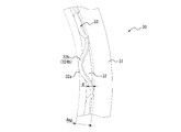
- FIG. 7 is a diagram for explaining the result of the analysis performed on the lock ring.
- FIG. 7A shows that the lock ring is attached to the pipe joint using the analysis model 300 corresponding to a part of the lock ring when the claw portion 32 is flat over the entire length in the extending direction ED.
- the result of analyzing the amount of deflection generated in the analysis model 300 is shown assuming that the force in the pulling direction PD acts on the lock ring in the state.
- FIG. 7B uses an analysis model 301 corresponding to a part of the lock ring when the claw portion 32 has a wave shape in a cross section perpendicular to the axial direction over the entire length in the extending direction ED.
- the result of analyzing the amount of deflection generated in the model 301 for analysis is shown assuming that a force in the pulling direction PD acts on the lock ring in a state where the lock ring is attached to the pipe joint.
- a force in the pulling direction PD acts on the lock ring in a state where the lock ring is attached to the pipe joint.
- FIGS. 7A and 7B when the claw portion 32 has a wave shape as shown in FIG. 7B, the claw portion 32 is flat as shown in FIG. 7A. Since the rigidity of the lock ring with respect to the force in the pulling direction PD is increased as compared with the case where the lock ring is made, the lock ring (particularly, the claw portion 32) is difficult to bend with respect to the force in the pulling direction PD.
- the plurality of claw portions 32 have a wave shape in a cross section perpendicular to the axial direction in at least a part of the extending direction ED, and thus are attached to the pipe joint 1.
- the lock ring 30 against the force in the pulling direction PD acting on the lock ring 30 from the tube body 2.
- the lock ring 30 (particularly, the claw portion 32) can be made difficult to bend with respect to the force in the drawing direction PD.
- claw part 32 is extending straight in the cross section along the radial direction of the ring part 31 in any circumferential direction position.
- the rigidity of the claw part 32 with respect to the force in the drawing direction PD can be increased as compared with the case where the claw part 32 swings in the plate thickness direction in the cross section along the radial direction of the ring part 31.
- the plurality of claw portions 32 have a wave shape in a cross section perpendicular to the axial direction at at least a tip portion 322 in the extending direction ED.
- the plurality of claw portions 32 have their tip portions 322 in the extending direction ED flattened in a cross section perpendicular to the axial direction. Rigidity can be increased, and as a result, excessive biting of the claw portion 32 into the pipe body 2 when the pipe body 2 is pulled out from the pipe joint 1 can be suppressed.
- the lock ring 30 is connected to the pipe joint 1 as compared with the case where the plurality of claw portions 32 are flat at the tip portion 322 in the extending direction ED in a cross section perpendicular to the axial direction.
- the depth and width of scratches that can be formed on the outer peripheral surface of the pipe body 2 by the claw portion 32 can be reduced.
- the sealing member 40 is disposed on the back side in the insertion direction of the insertion space 20 rather than the lock ring 30 as in the example of FIG. It is possible to suppress the formation of a gap between the outer peripheral surface of the pipe body 2 inserted into the pipe joint 1 and the sealing member 40, and to suppress fluid leakage (leakage in this example).
- the plurality of claw portions 32 When viewed as a whole, the plurality of claw portions 32 have no angularity in a cross section perpendicular to the axial direction at least at the distal end portion 322 in the extending direction ED, as in the examples of FIGS. It is preferable to form a smooth wave shape (that is, a wave shape with a radius). Thereby, the tube body 2 is formed in the pipe joint 1 as compared with the case where the plurality of claw portions 32 form a jagged wave shape in a cross section perpendicular to the axial direction at least at the tip portion 322 in the extending direction ED.
- a smooth wave shape that is, a wave shape with a radius
- claw part 32 can contact the pipe body 2 in a wider area
- the sealing member 40 is disposed on the back side in the insertion direction of the insertion space 20 and on the outer peripheral side of the insertion space 20 as in the example of FIG. Further, water leakage from between the sealing member 40 and the tube body 2 can be suppressed.
- the plurality of claw portions 32 when viewed as a whole, have a wave shape in a cross section perpendicular to the axial direction at least at the tip portion 322 in the extending direction ED.
- the both end portions 323 in the circumferential direction are gradually inclined toward the outer peripheral side toward the both ends 32c in the respective circumferential directions.
- “inclined” is not limited to the case of extending in a straight line, but also includes the case of extending while being curved.
- the recessed portions 324 are formed at both ends in the circumferential direction of the claw portion 32. 1 each, and a pair of depressions 324 connected to each other by one protrusion 325, or a generally W-shaped wave shape, or between a pair of depressions 324, There is a wave shape in which one or a plurality of protrusions 325 and one or a plurality of depressions 324 are alternately arranged one by one, or a shape consisting of only one depression 324.
- the shape of the claw portion 32 in a cross section perpendicular to the axial direction is preferably not a shape having the protruding portion 325 on at least one side in the circumferential direction of the claw portion 32.
- the claw portion 32 has a tip 32 b that has one recess 324 b at each end in the circumferential direction, and one pair of these recesses 324 b is one.
- the portions 324b have a wave shape in which the portions 324b are alternately arranged one by one or a shape having only one depression 324b.
- the edge 32 a on the inner peripheral side at the tip 32 b in the extending direction ED of the claw portion 32 is rounded in a cross section along the radial direction of the ring portion 31 ( That is, it is preferably not square.
- the outer peripheral surface of the pipe body 2 is prevented from being damaged by the inner peripheral edge 32a of the claw portion 32. it can.
- water leakage from between the sealing member 40 and the tube body 2 can be suppressed.
- the number of claw portions 32 included in the lock ring 30 is not limited to 16 as in this example, and may be smaller or larger than 16, for example.
- the total number of the protrusions 325 and the recesses 324 per one claw 32 is three in this example, but may be one, two, or four or more. .
- the wave-shaped amplitude of the tip 32b of the claw 32 ie, the maximum outer diameter position and the minimum inner diameter of the tip 32b of the claw 32 in the thickness direction of the tip 32b of the claw 32).
- Amp is 1.6 to 4.2 times the plate thickness d of the claw portion 32 (1.6d ⁇ Amp ⁇ 4.2d) (see FIG. 6).
- the amplitude Amp in the plate thickness direction formed by the tip 32b of the claw portion 32 is 1.8 to 3.1 times the plate thickness d of the claw portion 32 (1.8d ⁇ Amp ⁇ 3.1d) is more preferable.
- the slits 33 between the claw portions 32 are formed so that the slit width gradually narrows from the tip side to the root side in the extending direction ED of the claw portions 32. It is formed in a V shape.
- the slit width of the slit 33 is a width equal to or smaller than the plate thickness d of the claw portion 32 at a position corresponding to the tip 32b of the claw portion 32 in the extending direction ED of the claw portion 32.
- the lock ring of the present invention is not limited to the examples of FIGS. 3 to 6, and various modifications are possible. Hereinafter, modifications of the lock ring of the present invention will be described as examples.
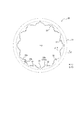
- FIGS. 8 to 11 show a first modification of the lock ring of the present invention, and correspond to FIGS. 3 to 6, respectively.
- the lock ring 30 of this example is different from the lock ring 30 of the example of FIGS. 3 to 6 described above in the shape of the claw portion 32.
- the lock ring 30 of this example is arranged along an annular (plate-like in this example) ring portion 31 and a circumferential direction of the ring portion 31, as in the above examples of FIGS. 3 to 6.
- a plurality (12 in the example shown in the figure) extending from the inner peripheral side end of the portion 31 (that is, the radially inner end) toward the inner peripheral side of the ring portion 31 and one side in the axial direction of the ring portion 31.
- the lock ring 30 is formed by subjecting a single metal plate to press processing, slit formation, bending formation, or the like, that is, the ring portion 31 and the claw portion 32 are integrally formed.
- the plurality of claw portions 32 have a wave shape in a substantially vertical cross section perpendicular to the axial direction. More specifically, when the plurality of claw parts 32 are viewed as a whole, the claw parts 32 have no angularity over the entire circumference in a cross section perpendicular to the axial direction in almost all of the extending directions ED of the claw parts 32. It has a smooth wave shape (that is, a wave shape with a radius). In addition, when the plurality of claw portions 32 are viewed as a whole, the circumferential end portions 323 gradually increase toward the circumferential ends 32c in almost all of the extending direction ED. It is inclined to go to the outer periphery.
- each claw portion 32 is U-shaped toward the inner peripheral side in a cross section perpendicular to the axial direction over almost the entire length of the extending direction ED when viewed as a single unit. It has a rounded wave shape composed of one hollow portion 324 extending so as to be hollow. More specifically, the claw portion 32 extends along an arc having a center of curvature on the outer peripheral side of the claw portion 32 at a central portion in the circumferential direction of the claw portion 32 in a cross section perpendicular to the axial direction.
- each claw portion 32 has a rounded shape, the distal end portion of the claw portion 32 is placed on the outer peripheral surface of the tube body 2 while the tube body 2 is inserted into the pipe joint 1 in the insertion direction ID. It can suppress that the wound to form becomes sharp.
- each claw portion 32 has a tip 32 b in the extending direction ED (on the opposite side of the claw portion 32 from the ring portion 31) when viewed individually.
- the end surface has a rounded wave shape composed of one hollow portion 324b extending so as to be U-shaped toward the inner peripheral side.
- the claw portion 32 has a distal end 32b in the extending direction ED extending along an arc having a center of curvature on the outer peripheral side of the claw portion 32 at a circumferential center portion of the distal end 32b.
- the claw portion The radius of curvature R of the arc shape having the center of curvature on the outer peripheral side of the tip 32b of the claw 32 formed by the inner peripheral edge 32a of the tip 32b of the tip 32 is preferably larger. 1.2 to 1.4 mm is preferable.
- the claw portion 32 is gradually at the circumferential end portions 323 of the claw portion 32 toward the both ends 32 c in the circumferential direction of the claw portion 32 in a cross section perpendicular to the axial direction. And extending along a circular arc having a center of curvature on the inner peripheral side of the claw portion 32. Since the claw portion 32 extends along an arc having a center of curvature on the inner peripheral side of the claw portion 32 at both circumferential end portions 323, the pipe body 2 inserted into the pipe joint 1 is removed from the pipe joint 1.
- each claw portion 32 has a tip 32 b at both ends in the circumferential direction of the tip 32 b when viewed from the tip 32 b as a single unit. As it goes to both ends in the circumferential direction of 32 b, it gradually extends so as to go to the outer peripheral side, and extends along an arc having a center of curvature on the inner peripheral side of the claw portion 32.
- the slits 33 between the claw portions 32 are formed so that the slit width gradually decreases from the tip side to the root side in the extending direction ED of the claw portions 32. It is formed in a U shape.
- the slit width (length measured along the circumferential direction) of the slit 33 is made larger than the plate thickness d of the claw portion 32 at a position corresponding to the tip 32b of the claw portion 32 in the extending direction ED of the claw portion 32. ing.
- a suitable value for the slit width of the slit 33 is determined by the plate thickness d of the claw portion 32 and the length in the extending direction ED.
- the slit 33 By enlarging the slit 33 in this manner, the claw portion 32 is easily tilted against the force applied from the tube body 2 while the tube body 2 is inserted into the pipe joint 1 in the insertion direction ID. It can suppress effectively that the front-end
- the slit 33 extends to a position as close as possible to the root of the claw portion 32 (preferably to the root) in the extending direction ED of the claw portion 32 as in the example of FIG. It is preferable. However, the slit 33 may be terminated at a position before reaching the root of the claw part 32 in the extending direction ED of the claw part 32.
- the edge 32 a on the inner peripheral side of the tip 32 b of the claw portion 32 is not rounded but is angular in the cross section along the radial direction of the ring portion 31.
- the amplitude Amp in the plate thickness direction formed by the tip 32b of the claw portion 32 is 1.6 to 4.2 times the plate thickness d of the claw portion 32 (1. 6d ⁇ Amp ⁇ 4.2d) is preferable, and 1.8 to 3.1 times the plate thickness d (1.8d ⁇ Amp ⁇ 3.1d) is more preferable.
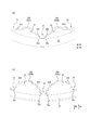
- FIG. 12 shows a second modification of the lock ring of the present invention.
- FIG. 12A shows a part of the lock ring 30 when viewed in plan along the axial direction as shown in FIG.
- FIG. 12B shows the state of the lock ring 30 shown in FIG. 12A when viewed obliquely as shown in FIG.
- the lock ring 30 of this example is different from the lock ring 30 of the first modified example of FIGS. 7 to 11 described above only in that the claw portion 32 has a notch 326.
- each claw portion 32 has a notch 326 at the end of at least one side (both sides in this example) of the tip 32 b in the circumferential direction.
- the notch 326 is formed in a shape curved convexly toward the base side of the claw portion 32.
- the claw portion 32 of the first modified example of FIGS. 7 to 11 does not have the notch 326, and the length in the extending direction ED of the claw portion 32 is substantially constant along the circumferential direction.
- the claw portion 32 of the second modified example has a length in the extending direction ED that is gradually shortened toward the circumferential end 32c of the claw portion 32 at the circumferential portion where the notch 326 is provided. Has been.
- the notch 326 at the tip 32b of the claw part 32 the pipe body of the claw part 32 of the lock ring 30 when the pipe body 2 inserted into the pipe joint 1 is pulled out from the pipe joint 1. Excessive biting into the tube 2 can be further suppressed, and as a result, the claw 32 of the lock ring 30 can be effectively suppressed from penetrating the tube 2 and biting the tube 2.
- the claw portion 32 may have a notch 326 only at the end portion on one side in the circumferential direction of the tip 32b. Further, only some of the claw portions 32 among the plurality of claw portions 32 may have the cutout 326. In the example of FIG. 12, the depth of the notch 236 in the extending direction ED of the claw portion 32 is shallower than the depth of the slit 33 in the extending direction ED of the claw portion 32.
- the notch 326 of the claw portion 32 of the second modification may be provided at an end portion on at least one side in the circumferential direction of the tip 32b of the claw portion 32 of the example of FIGS.
- the lock ring according to the present invention can be used for pipe joints.
- the pipe joint by this invention can be utilized for piping for arbitrary fluids, such as cold water, warm water, oil, gas, for example.
Landscapes
- Engineering & Computer Science (AREA)
- General Engineering & Computer Science (AREA)
- Mechanical Engineering (AREA)
- Quick-Acting Or Multi-Walled Pipe Joints (AREA)
Abstract
ロックリング30は、管継手1に差し込まれた管体2が管継手から抜け出るのを阻止するための、ロックリングであって、環状のリング部31と、リング部の周方向に沿って配列され、それぞれリング部から内周側及びリング部の軸線方向一方側へ向かう延在方向へ延在する、複数の板状の爪部32と、を備え、複数の爪部は、その少なくとも一部分で、軸線方向に垂直な断面において波形状をなす。
Description
この発明は、管継手に差し込まれた管体が管継手から抜け出るのを阻止するためのロックリング、及び管継手に関するものである。
本願は、2017年3月14日に、日本に出願された特願2017-048593号に基づく優先権を主張するものであり、その内容の全文をここに援用する。
本願は、2017年3月14日に、日本に出願された特願2017-048593号に基づく優先権を主張するものであり、その内容の全文をここに援用する。
従来、管継手に差し込まれた管体が管継手から抜け出るのを阻止するためのロックリング(係止リング)として、管継手に差し込まれた管体に外周側から食い込むように構成された複数の爪部(食い込み歯)が、それぞれ平坦な板状であるものが知られている(例えば、特許文献1)。
しかしながら、上述したようなロックリングを備えた管継手においては、管継手に差し込まれた管体に、管体を管継手から引き抜く方向の力が付与された場合に、ロックリングの爪部が、管体に過剰に食い込んで、管体を貫通するおそれがあった。
この発明は、上述した課題を解決するためのものであり、管継手に差し込まれた管体への過剰な食い込みを抑制できるロックリング、及び、管継手に差し込まれた管体へのロックリングの過剰な食い込みを抑制できる管継手を、提供することを目的とするものである。
本発明のロックリングは、管継手に差し込まれた管体が前記管継手から抜け出るのを阻止するための、ロックリングであって、環状のリング部と、前記リング部の周方向に沿って配列され、それぞれ前記リング部から内周側及び前記リング部の軸線方向一方側へ向かう延在方向へ延在する、複数の板状の爪部を備え、前記複数の爪部は、その少なくとも一部分で、前記軸線方向に垂直な断面において波形状をなすものである。
本発明の管継手は、前記管体が差し込まれる差込空間を区画する管継手本体と、前記差込空間の外周側に配置された、上記のロックリングと、前記差込空間の外周側又は内周側に配置され、前記管体が前記差込空間に差し込まれた状態において、前記管継手本体と前記管体との間を流体密に封止する、封止部材と、を備えている。
この発明によれば、管継手に差し込まれた管体への過剰な食い込みを抑制できるロックリング、及び、管継手に差し込まれた管体へのロックリングの過剰な食い込みを抑制できる管継手を、提供できる。
以下に、図面を参照しつつ、この発明に係るロックリング及び管継手の実施形態を例示説明する。
〔管継手〕
図1及び図2は、本発明の一実施形態に係る管継手1を示している。本実施形態の管継手1は、給水・給湯用の配管に好適に使用し得るものであるが、水以外の液体、あるいは気体を含む、あらゆる流体のための配管にも使用し得るものである。
図1は本実施形態の管継手1の斜視図であり、図2は図1の管継手1の一部を、管継手1の軸線方向に沿う断面とともに示す、部分断面側面図である。なお、管継手1の軸線方向(以下、単に「軸線方向」ということがある。)とは、管継手1の中心軸線に沿う方向を意味する。図1及び図2の例において、管継手1の中心軸線は、後述するロックリング30の中心軸線Oと一致する。
本例において、管継手1における軸線方向両側には、管体2を差し込むための、図2の例では環状の、差込空間20が、図2の左右両側に1つずつ、計2つ形成されている。図2では、説明の便宜のため、左側の差込空間20のみに管体2が差し込まれた状態で示している。管継手1に差し込まれる管体2は、例えばポリブテン製又は架橋ポリエチレン製の給水・給湯用パイプである。
ただし、管継手1は、差込空間20を、1つのみ、あるいは3つ以上、有していてもよい。
本実施形態の管継手1は、管継手本体10と、本発明の一実施形態に係るロックリング30と、封止部材40と、を備えている。
管継手本体10は、本例では軸線方向両側に差込空間20を区画している。本例において、管継手本体10は、外筒部材11と、内筒部材12と、被嵌め込み部材13と、中間スペーサ部材14と、を備えている。
管継手本体10は、本例では軸線方向両側に差込空間20を区画している。本例において、管継手本体10は、外筒部材11と、内筒部材12と、被嵌め込み部材13と、中間スペーサ部材14と、を備えている。
外筒部材11は、例えば樹脂又は金属からなり、図の例では管継手1の軸線方向の全長にわたって延在する略円筒状をなしている。図2に示すように、外筒部材11の内周面には、管継手1の軸線方向のほぼ中央に、内周側へ突出する段部11aが設けられている。
図の例では、1つの差込空間20に対して、内筒部材12、被嵌め込み部材13、中間スペーサ部材14、ロックリング30、及び封止部材40が、1つずつ設けられている。
以下の説明では、軸線方向に沿う向きのうち、図2の左側を指す向きを「軸線方向第1側」とし、図2の右側を指す向きを「軸線方向第2側」とする。
また、以下の説明では、軸線方向第2側(図2の右側)の差込空間20に対応して設けられた内筒部材12、被嵌め込み部材13、中間スペーサ部材14、ロックリング30、及び封止部材40の構成について説明する。ただし、軸線方向第1側(図2の左側)の差込空間20に対応して設けられた内筒部材12、被嵌め込み部材13、中間スペーサ部材14、ロックリング30、及び封止部材40の構成も同様である。
軸線方向第2側(図2の右側)の差込空間20においては、軸線方向第1側へ向かう方向が、管体2を差込空間20へ差し込む方向(以下、「差し込み方向ID」という。)であり、軸線方向第2側へ向かう方向が、管体2を差込空間20から引き抜く方向(以下、「引き抜き方向PD」という。)である。
内筒部材12は、例えば樹脂又は金属からなり、外筒部材11の内周側に挿入されている。内筒部材12は、外筒部材11よりも内周側へ離間した小径管部12aと、小径管部12aよりも外周側に位置し、外筒部材11の内周面に当接する大径管部12bと、小径管部12a及び大径管部12bどうしを連結し、外筒部材11の段部11aに当接する連結部12cと、を有している。小径管部12aの内周面は、管継手1の流路を区画している。一方、小径管部12aの外周面、大径管部12bの内周面、及び連結部12cの軸線方向第2側(差込空間20の入口側)を向く面は、差込空間20の一部を区画している。
中間スペーサ部材14は、例えば樹脂からなり、外筒部材11の内周側、内筒部材12の小径管部12aの外周側、かつ、内筒部材12の大径管部12bに対して軸線方向第2側(差込空間20の入口側)に、配置されている。
被嵌め込み部材13は、例えば樹脂からなり、内筒部材12の小径管部12aの外周側、かつ、中間スペーサ部材14に対して軸線方向第2側(差込空間20の入口側)に配置され、外筒部材11の内周面に嵌め込まれている。
中間スペーサ部材14及び被嵌め込み部材13のそれぞれの内周面は、差込空間20の一部を区画している。
被嵌め込み部材13は、例えば樹脂からなり、内筒部材12の小径管部12aの外周側、かつ、中間スペーサ部材14に対して軸線方向第2側(差込空間20の入口側)に配置され、外筒部材11の内周面に嵌め込まれている。
中間スペーサ部材14及び被嵌め込み部材13のそれぞれの内周面は、差込空間20の一部を区画している。
封止部材40は、例えば弾性体のOリングからなり、本例では、差込空間20の外周側、かつ、軸線方向における内筒部材12の大径管部12bと中間スペーサ部材14との間で、全周にわたって設けられている。管体2が差込空間20に差し込まれていない状態において、封止部材40の内径は、内筒部材12の大径管部12bの内径、中間スペーサ部材14の内径、及び被嵌め込み部材13の内径のいずれよりも、若干小さくされている。封止部材40は、管体2が差込空間20内に差し込まれると、管体2の外周面に密着するように変形し、これにより、管継手本体10と管体2との間の流体を密に封止する。
本実施形態のロックリング30は、例えば金属からなり、差込空間20の外周側、かつ、軸線方向における中間スペーサ部材14と被嵌め込み部材13との間に、配置されている。図2の例において、ロックリング30は、差込空間20よりも外周側において全周にわたって連続する、環状の板状のリング部31と、リング部31の周方向に沿って配列され、それぞれリング部31の内周側端部から、リング部31の内周側かつ差込空間20の差し込み方向奥側(差込空間20の入口とは反対側。リング部31の軸線方向一方側。)へ向かって延在する、複数の板状の爪部32と、を有している。管体2が差込空間20に差し込まれていない状態において、ロックリング30の爪部32の内径は、内筒部材12の大径管部12bの内径、中間スペーサ部材14の内径、及び被嵌め込み部材13の内径のいずれよりも、若干小さくされている。管体2が差込空間20に挿入されると、ロックリング30の爪部32の先端部分(内周側の端部分)が管体2の外周面に食い込んで係止する。この状態において、差込空間20に差し込まれた管体2に、引き抜き方向PDの力が付与されると、ロックリング30の爪部32が軸線方向第2側(差込空間20の入口側)へ撓みながら管体2の外周面にさらに食い込んで、管体2が差込空間20から抜け出るのを阻止するように機能する。
なお、本実施形態の管継手1は、上述したものに限られず、様々な変形例が可能である。
例えば、封止部材40は、ロックリング30よりも軸線方向第2側(差込空間20の入口側)に配置されてもよい。その場合、封止部材40は、例えば、被嵌め込み部材13の内周面において周方向に延在する環状溝(図示せず)に収容されてもよい。
あるいは、封止部材40は、例えば内筒部材12の小径管部12aの外周面において周方向に延在する環状溝(図示せず)に収容される等して、差込空間20の内周側に配置されてもよい。この場合、封止部材40は、管体2が差込空間20内に差し込まれると、管体2の内周面に密着するように変形し、これにより、管継手本体10と管体2との間の流体を密に封止する。
例えば、封止部材40は、ロックリング30よりも軸線方向第2側(差込空間20の入口側)に配置されてもよい。その場合、封止部材40は、例えば、被嵌め込み部材13の内周面において周方向に延在する環状溝(図示せず)に収容されてもよい。
あるいは、封止部材40は、例えば内筒部材12の小径管部12aの外周面において周方向に延在する環状溝(図示せず)に収容される等して、差込空間20の内周側に配置されてもよい。この場合、封止部材40は、管体2が差込空間20内に差し込まれると、管体2の内周面に密着するように変形し、これにより、管継手本体10と管体2との間の流体を密に封止する。
また、図2に示す例では、ロックリング30のリング部31が、管継手1の軸線方向に対して垂直な仮想平面に沿って環状に延在しているが、リング部31は、管継手1の軸線方向に対して非垂直に交わる仮想平面に沿って環状に延在していてもよい。
〔ロックリング〕
つぎに、図3~図7を参照して、本実施形態のロックリング30についてさらに詳しく説明する。図3~図6に示すロックリング30は、図1及び図2に示す管継手1に備えられたロックリング30と同じものである。図3はロックリング30を示す平面図である。図4は、ロックリング30を一部切り欠いて示す斜視図である。図5は、ロックリング30の一部を、図3のA-A線に沿う断面とともに示す、部分断面斜視図である。図3のA-A線は、ロックリング30のリング部31の径方向に沿うものである。図6は、ロックリング30の一部を、図4の矢印Bから観た状態で示す、斜視図であり、より具体的には、ロックリング30の一部を、ロックリング30の爪部32の先端側から観た様子を示している。
つぎに、図3~図7を参照して、本実施形態のロックリング30についてさらに詳しく説明する。図3~図6に示すロックリング30は、図1及び図2に示す管継手1に備えられたロックリング30と同じものである。図3はロックリング30を示す平面図である。図4は、ロックリング30を一部切り欠いて示す斜視図である。図5は、ロックリング30の一部を、図3のA-A線に沿う断面とともに示す、部分断面斜視図である。図3のA-A線は、ロックリング30のリング部31の径方向に沿うものである。図6は、ロックリング30の一部を、図4の矢印Bから観た状態で示す、斜視図であり、より具体的には、ロックリング30の一部を、ロックリング30の爪部32の先端側から観た様子を示している。
上述したように、本実施形態のロックリング30は、環状の(本例では板状の)リング部31と、リング部31の周方向に沿って配列され、それぞれリング部31の内周側端部(すなわち径方向内側端部)から、リング部31の内周側及びリング部31の軸線方向一方側へ向かって延在する、複数(図の例では16枚)の板状の爪部32と、を備えている。爪部32どうしの間には、スリット33が形成されている。
なお、リング部31の軸線方向(以下、単に「軸線方向」ということがある。)とは、ロックリング30の中心軸線O(リング部31の中心軸線と同じ。)に沿う方向を意味する。
図2を参照しながら上述したように、ロックリング30は、管継手1に装着される際には、爪部32が、リング部31から、リング部31の内周側かつ差込空間20の差し込み方向奥側へ向かって延在するように、指向される。
なお、リング部31の軸線方向(以下、単に「軸線方向」ということがある。)とは、ロックリング30の中心軸線O(リング部31の中心軸線と同じ。)に沿う方向を意味する。
図2を参照しながら上述したように、ロックリング30は、管継手1に装着される際には、爪部32が、リング部31から、リング部31の内周側かつ差込空間20の差し込み方向奥側へ向かって延在するように、指向される。
本例では、ロックリング30が、一枚の金属板にプレス加工や、スリット形成及び折り曲げ成形等を施すことにより形成されており、すなわち、リング部31と爪部32とが一体に構成されている。ただし、リング部31と爪部32とは、互いに別体に形成されて互いに固定されていてもよい。その場合、例えばリング部31を樹脂製とし、爪部32を金属製とする等、リング部31及び爪部32の材料を異ならせても良い。
また、爪部32は、リング部31の径方向中間部分から延在していてもよい。
また、爪部32は、リング部31の径方向中間部分から延在していてもよい。
図4は、一部の爪部32について、2つの異なる軸線方向位置での軸線方向に垂直な仮想平面S1、S2に沿う爪部32の断面を、それぞれ示している。図4に示すように、複数の爪部32は、その少なくとも一部分で、軸線方向に垂直な断面において、波形状をなしている。より具体的に、複数の爪部32は、その内周側及び軸線方向一方側への延在方向(以下、単に「爪部32の延在方向ED」ともいう。)の少なくとも一部分で、及び/又は、周方向の少なくとも一部分で、軸線方向に垂直な断面において、波形状をなしている。さらに具体的に、図の例では、複数の爪部32は、爪部32の延在方向EDの根元部分(爪部32の、リング部31側の端部分)321から、その延在方向EDの先端(爪部32の、リング部31とは反対側の端面)32bまでにわたる、爪部32の延在方向EDのほぼ全部で、軸線方向に垂直な断面において、全周にわたって、波形状をなしている。
ここで、「軸線方向に垂直な断面において波形状をなしている」とは、複数の爪部32の、軸線方向に垂直な断面を、複数の爪部32を全体としてリング部31の周方向に沿って観たときに、複数の爪部32が、リング部31の径方向に振幅している(すなわち、外周側への延在と内周側への延在とを交互に繰り返している)ことを指している。このとき、爪部32どうしの間の間隙では、爪部32どうしを滑らかに繋げて観るものとする。
図4及び図6に示す例において、複数の爪部32は、リング部31の周方向に沿って観たときに、全周にわたって、その板厚方向に振幅するような、波形状をなしている。また、複数の爪部32は、図の例において、その延在方向EDに垂直な断面において、全周にわたって、波形状をなしている、ともいえる。また、図に示す例では、爪部32の板厚方向の振幅は、爪部32の延在方向EDの先端側に向かって徐々に増大されている。
なお、本明細書において、「波形状」とは、特に断りがない限り、例えば、アール付きの波形状(すなわち、角張りの無い、滑らかな波形状)や、ギザギザ状の波形状(すなわち、角張った波形状)等、あらゆる形態の波形状を指している。図3~図6の例では、複数の爪部32の波形状は、アール付きの波形状である。
また、本明細書において、爪部32の延在方向EDの先端32bは、爪部32の、リング部31とは反対側の末端(端面)を指している。一方、爪部32の延在方向EDの根元部分321とは、該爪部32の延在方向EDの根元側(リング部31側)の、該爪部32の延在方向EDの全長の30%程度の延在方向長さを持つ端部分を指す。また、爪部32の延在方向EDの先端部分322とは、該爪部32の延在方向EDの先端32b側の、該爪部32の延在方向EDの全長の30%程度の延在方向長さを持つ端部分を指す。
図4に示すように、複数の爪部32のうち少なくとも一部の爪部32(好ましくは全部の爪部32)は、爪部32を単体で観たときに、その延在方向EDの少なくとも一部分で、軸線方向に垂直な断面において、平坦状ではなく、内周側に向かってU字状又はV字状に窪むように延在した窪み部324、又は、外周側に向かってU字状又はV字状に突出するように延在した突出部325を、少なくとも1つ有する。
本明細書において、軸線方向に垂直な断面において、爪部32が「平坦状」であるとは、軸線方向に垂直な断面において、各爪部32がそれぞれ直線状に延在していること、あるいは、各爪部32がこれら全体に共通の円に沿ってそれぞれ円弧状に延在しており、これにより、複数の爪部32がこれらを全体として観たときにリング部31の径方向に振幅していないこと、のいずれかに該当すること意味している。
複数の爪部32のうち少なくとも一部の爪部32(好ましくは全部の爪部32)は、爪部32を単体で観た時に、その延在方向EDの少なくとも一部分で、軸線方向に垂直な断面において、1つの窪み部324からなる波形状でもよいし、あるいは、1つの突出部325からなる波形状でもよいし、あるいは、1つ又は複数の突出部325及び1つ又は複数の窪み部324が1つずつ交互に配列されてなる波形状でもよい。
図4の例では、各爪部32が、その延在方向EDのほぼ全長にわたって、軸線方向に垂直な断面において、1対の窪み部324どうしの間に1つの突出部325が配置されてなる、全体的にW字状の波形状を有している。
同様に、図4及び図6に示すように、複数の爪部32のうち少なくとも一部の爪部32(好ましくは全部の爪部32)は、爪部32を単体で観たときに、その延在方向EDの先端32bが、平坦状ではなく、内周側に向かってU字状又はV字状に窪むように延在した窪み部324b、又は、外周側に向かってU字状又はV字状に突出するように延在した突出部325bを、少なくとも1つ有すると、好適である。
複数の爪部32のうち少なくとも一部の爪部32(好ましくは全部の爪部32)は、爪部32を単体で観た時に、その延在方向EDの先端32bが、1つの窪み部324bからなる波形状でもよいし、あるいは、1つの突出部325bからなる波形状でもよいし、あるいは、1つ又は複数の突出部325b及び1つ又は複数の窪み部324bが1つずつ交互に配列されてなる波形状でもよい。
図4及び図6の例では、各爪部32の延在方向EDの先端32bが、1対の窪み部324bどうしの間に1つの突出部325bが配置されてなる、全体的にW字状の波形状を有している。
複数の爪部32のうち少なくとも一部の爪部32(好ましくは全部の爪部32)は、爪部32を単体で観た時に、その延在方向EDの先端32bが、1つの窪み部324bからなる波形状でもよいし、あるいは、1つの突出部325bからなる波形状でもよいし、あるいは、1つ又は複数の突出部325b及び1つ又は複数の窪み部324bが1つずつ交互に配列されてなる波形状でもよい。
図4及び図6の例では、各爪部32の延在方向EDの先端32bが、1対の窪み部324bどうしの間に1つの突出部325bが配置されてなる、全体的にW字状の波形状を有している。
複数の爪部32は、これらを全体として観たときに、その延在方向EDの一部のみで、軸線方向に垂直な断面において波形状をなしていてもよい。例えば、複数の爪部32は、その延在方向EDの根元部分321のみで、あるいは、その延在方向EDの先端部分322のみで、波形状をなしていてもよい。その場合、複数の爪部32は、その延在方向EDの他の部分では、平坦状をなしているものとする。
本例のように、複数の爪部32が、これらを全体として観たときに、その延在方向EDの先端部分322で、軸線方向に垂直な断面において波形状をなしている場合は、仮に複数の爪部32がその延在方向EDの根元部分321で、軸線方向に垂直な断面において波形状をなしている場合に比べて、ロックリング30の製造の際に、波形状を形成するための折り曲げ成形が、より容易となる。
なお、複数の爪部32のうち一部の爪部32のみが、その延在方向EDの全長にわたって、軸線方向に垂直な断面において平坦状をなしていてもよい。
本例のように、複数の爪部32が、これらを全体として観たときに、その延在方向EDの先端部分322で、軸線方向に垂直な断面において波形状をなしている場合は、仮に複数の爪部32がその延在方向EDの根元部分321で、軸線方向に垂直な断面において波形状をなしている場合に比べて、ロックリング30の製造の際に、波形状を形成するための折り曲げ成形が、より容易となる。
なお、複数の爪部32のうち一部の爪部32のみが、その延在方向EDの全長にわたって、軸線方向に垂直な断面において平坦状をなしていてもよい。
図7は、ロックリングについて行った解析の結果を説明するための図である。図7(a)は、爪部32がその延在方向EDの全長にわたって平坦状をなす場合の、ロックリングの一部分に相当する解析用モデル300を用いて、ロックリングが管継手に装着された状態において、ロックリングに引き抜き方向PDの力が作用した場合を想定して、この解析用モデル300に生じるたわみ量を解析した結果を示している。図7(b)は、爪部32が、その延在方向EDの全長にわたって、軸線方向に垂直な断面において波形状をなしている場合の、ロックリングの一部分に相当する解析用モデル301を用いて、ロックリングが管継手に装着された状態において、ロックリングに引き抜き方向PDの力が作用した場合を想定して、この解析用モデル301に生じるたわみ量を解析した結果を示している。図7(a)、図7(b)からわかるように、図7(b)に示すように爪部32が波形状をなす場合、図7(a)に示すように爪部32が平坦状をなす場合に比べて、引き抜き方向PDの力に対するロックリングの剛性が高まるため、引き抜き方向PDの力に対してロックリング(特には、爪部32)がたわみにくくなる。
本実施形態のロックリング30によれば、複数の爪部32が、その延在方向EDの少なくとも一部分で、軸線方向に垂直な断面において波形状をなしているため、管継手1に装着された状態において、管継手1に一旦差し込まれた管体2に対して引き抜き方向PDの力が作用した場合に、管体2からロックリング30に作用する引き抜き方向PDの力に対して、ロックリング30の剛性を高めることができ、ひいては、該引き抜き方向PDの力に対してロックリング30(特には、爪部32)をたわみにくくすることができる。これにより、管継手1に差し込まれた管体2が管継手1から引き抜かれる際の、ロックリング30の爪部32の、管体2への過剰な食い込みを抑制でき、ひいては、ロックリング30の爪部32が管体2に貫通して管体2を食いちぎるのを抑制できる。
なお、図5に示すように、爪部32は、いずれの周方向位置でも、リング部31の径方向に沿う断面において、まっすぐに延在しているのが好ましい。これにより、例えば爪部32がリング部31の径方向に沿う断面においてその板厚方向に振幅している場合に比べて、引き抜き方向PDの力に対する爪部32の剛性を高めることができ、ひいては、管体2が管継手1から引き抜かれる際の、爪部32の管体2への過剰な食い込みを抑制できる。
なお、複数の爪部32は、その延在方向EDの少なくとも先端部分322で、軸線方向に垂直な断面において波形状をなしているのが、好ましい。
これにより、仮に複数の爪部32が、その延在方向EDの先端部分322で、軸線方向に垂直な断面において平坦状をなしている場合に比べて、引き抜き方向PDの力に対する爪部32の剛性を高めることができ、ひいては、管体2が管継手1から引き抜かれる際の、爪部32の管体2への過剰な食い込みを抑制できる。
また、この場合、仮に複数の爪部32が、その延在方向EDの先端部分322で、軸線方向に垂直な断面において平坦状をなしている場合に比べて、ロックリング30を管継手1に装着した状態において、管体2が管継手1に差し込まれる際に、爪部32が管体2の外周面に形成し得る傷の深さや幅を低減できる。これにより、図2の例のようにロックリング30よりも差込空間20の差込方向奥側、かつ、差込空間20の外周側に、封止部材40が配置された管継手1において、管継手1に差し込まれた管体2の外周面と封止部材40との間に間隙ができるのを抑制し、ひいては、流体漏れ(本例では、漏水)を抑制できる。
複数の爪部32は、これらを全体として観たときに、図3~図6の例のように、その延在方向EDの少なくとも先端部分322で、軸線方向に垂直な断面において角張りの無い滑らかな波形状(すなわちアール付きの波形状)をなすことが、好ましい。これにより、仮に複数の爪部32が、その延在方向EDの少なくとも先端部分322で、軸線方向に垂直な断面においてギザギザ状の波形状をなす場合に比べて、管継手1に管体2が差し込まれる際に、爪部32が、管体2に、より広い領域で接触できる(面接触できる)ので、その分、管体2を傷つける傷の深さを低減できる。これにより、例えば図2の例のようにロックリング30よりも差込空間20の差込方向奥側、かつ、差込空間20の外周側に、封止部材40が配置された管継手1において、封止部材40と管体2との間からの漏水を抑制することができる。
図4に示す例のように、複数の爪部32は、これらを全体として観たときに、その延在方向EDの少なくとも先端部分322で、軸線方向に垂直な断面において波形状をなしているとともに、その延在方向EDの少なくとも先端部分322で、それぞれの周方向の両端部分323が、それぞれの周方向の両端32cへ向かうにつれて徐々に外周側へ向かうように傾いていると、好適である。
ここで、「傾いている」とは、直線状に延在する場合に限られず、湾曲しながら延在する場合も含まれる。
このような構成を持つ爪部32の、軸線方向に垂直な断面における具体的な形状としては、例えば、図4の例のように、該爪部32の周方向の両端側に窪み部324を1つずつ有し、これら1対の窪み部324どうしが1つの突出部325によって連結されてなる、全体的にW字状の波形状、あるいは、1対の窪み部324どうしの間で、1つ又は複数の突出部325及び1つ又は複数の窪み部324が1つずつ交互に配列されてなる波形状、あるいは、1つの窪み部324のみからなる形状がある。
言い換えれば、爪部32の、軸線方向に垂直な断面における形状は、突出部325を該爪部32の周方向の少なくとも一方側に有する形状ではないことが好ましい。
これにより、ロックリング30が装着された管継手1に、管体2が差し込まれる際に、爪部32の周方向両端部分323の内周側の端縁によって、管体2の外周面に傷が付くのを抑制できる。
なお、本明細書において、爪部32の周方向の端32cは、爪部32の周方向の末端(端面)を指している。
同様に、図4及び図6に示すように、爪部32は、その先端32bが、その周方向の両端側に窪み部324bを1つずつ有し、これら1対の窪み部324bどうしが1つの突出部325bによって連結されてなる、全体的にW字状の波形状、あるいは、1対の窪み部324bどうしの間で、1つ又は複数の突出部325b及び1つ又は複数の他の窪み部324bが1つずつ交互に配列されてなる波形状、あるいは、1つの窪み部324bのみからなる形状であると、好適である。
図5に示すように、本例では、爪部32の延在方向EDの先端32bにおける、内周側の端縁32aは、リング部31の径方向に沿う断面において、アール付けされている(すなわち角張っていない)と、好適である。これにより、ロックリング30が装着された管継手1に、管体2が差し込まれる際に、爪部32の内周側の端縁32aによって、管体2の外周面に傷が付くのを抑制できる。これにより、例えば図2の例のようにロックリング30よりも差込空間20の差込方向奥側、かつ、差込空間20の外周側に、封止部材40が配置された管継手1において、封止部材40と管体2との間からの漏水を抑制することができる。
ロックリング30が有する爪部32の枚数は、本例のように16枚に限られず、例えば16枚より少なくても多くてもよい。
また、軸線方向に垂直な断面において、1つの爪部32当たりの突出部325及び窪み部324の合計数は、本例では3つであるが、1つ、2つ、又は4つ以上でもよい。
また、軸線方向に垂直な断面において、1つの爪部32当たりの突出部325及び窪み部324の合計数は、本例では3つであるが、1つ、2つ、又は4つ以上でもよい。
爪部32の先端32bがなす波形状の、板厚方向の振幅が大きいほど、引き抜き方向PDの力に対する爪部32の剛性を高められる一方、管継手1に管体2が差し込まれる際の管体2への傷付きが悪化したり、管継手1に管体2を差し込むのに要する力が増大したりするおそれがある。この観点から、爪部32の先端32bがなす波形状の、板厚方向の振幅(すなわち、爪部32の先端32bの板厚方向における、爪部32の先端32bの最大外径位置と最小内径位置との間の距離)Ampが、爪部32の板厚dの1.6~4.2倍(1.6d≦Amp≦4.2d)であると、好適である(図6参照)。特に図6の例では、爪部32の先端32bがなす波形状の、板厚方向の振幅Ampは、爪部32の板厚dの1.8~3.1倍(1.8d≦Amp≦3.1d)であると、より好適である。
図4及び図6に示すように、本例において、爪部32どうしの間のスリット33は、爪部32の延在方向EDにおける先端側から根元側に向かうにつれて徐々にスリット幅が狭くなるような、V字状に形成されている。スリット33のスリット幅は、爪部32の延在方向EDにおける爪部32の先端32bに対応する位置において、爪部32の板厚d以下の幅である。
本発明のロックリングは、図3~図6の例のものに限られず、様々な変形例が可能である。以下、本発明のロックリングの変形例について、例示説明する。
(ロックリングの第1変形例)
図8~図11は、本発明のロックリングの第1変形例を示しており、それぞれ図3~図6に対応する図である。本例のロックリング30は、爪部32の形状が、上述した図3~図6の例のロックリング30とは異なる。
本例のロックリング30は、上述した図3~図6の例と同様に、環状の(本例では板状の)リング部31と、リング部31の周方向に沿って配列され、それぞれリング部31の内周側端部(すなわち径方向内側端部)から、リング部31の内周側及びリング部31の軸線方向一方側へ向かって延在する、複数(図の例では12枚)の板状の爪部32と、を備えている。ロックリング30は、一枚の金属板にプレス加工や、スリット形成及び折り曲げ成形等を施すことにより形成されており、すなわち、リング部31と爪部32とが一体に構成されている。複数の爪部32は、そのほぼ全体において、軸線方向に垂直な断面において、波形状をなしている。より具体的に、複数の爪部32は、それらを全体として観たときに、爪部32の延在方向EDのほぼ全部で、軸線方向に垂直な断面において、全周にわたって、角張りの無い滑らかな波形状(すなわちアール付きの波形状)をなしている。また、複数の爪部32は、これらを全体として観たときに、その延在方向EDのほぼ全部で、それぞれの周方向の両端部分323が、それぞれの周方向の両端32cへ向かうにつれて徐々に外周側へ向かうように傾いている。
図9に示すように、各爪部32は、それぞれを単体で観たときに、その延在方向EDのほぼ全長にわたって、軸線方向に垂直な断面において、内周側に向かってU字状に窪むように延在した1つの窪み部324からなる、丸みを帯びた波形状を有している。より具体的に、爪部32は、軸線方向に垂直な断面において、爪部32の周方向中央部分で、爪部32の外周側に曲率中心を有する円弧に沿って延在している。この構成によれば、爪部32が丸みを帯びた形状を有するため、管体2が管継手1に差し込み方向IDに差し込まれる間に、爪部32の先端部分が管体2の外周面に形成する傷が鋭利となるのを抑制をできる。
同様に、図9及び図11に示すように、各爪部32は、それぞれを単体で観たときに、その延在方向EDの先端32b(爪部32の、リング部31とは反対側の端面)が、内周側に向かってU字状に窪むように延在した1つの窪み部324bからなる、丸みを帯びた波形状を有している。爪部32は、その延在方向EDの先端32bが、先端32bの周方向中央部分で、爪部32の外周側に曲率中心を有する円弧に沿って延在している。これにより、管体2が管継手1に差し込み方向IDに差し込まれる間に、爪部32の先端部分が管体2の外周面に形成する傷が鋭利となるのを抑制をできる。
同様に、図9及び図11に示すように、各爪部32は、それぞれを単体で観たときに、その延在方向EDの先端32b(爪部32の、リング部31とは反対側の端面)が、内周側に向かってU字状に窪むように延在した1つの窪み部324bからなる、丸みを帯びた波形状を有している。爪部32は、その延在方向EDの先端32bが、先端32bの周方向中央部分で、爪部32の外周側に曲率中心を有する円弧に沿って延在している。これにより、管体2が管継手1に差し込み方向IDに差し込まれる間に、爪部32の先端部分が管体2の外周面に形成する傷が鋭利となるのを抑制をできる。
上述した管体2の差込時の傷を抑制する観点及び製造性の観点からは、図8に示すように、本例のロックリング30を軸線方向に沿って平面視したときに、爪部32の先端32bの内周側端縁32aがその周方向中央部分でなす、爪部32の先端32bの外周側に曲率中心を有する円弧形状の曲率半径Rが、大きいほうがよく、具体的には、1.2~1.4mmであると好適である。
また、図9に示すように、本例において、爪部32は、軸線方向に垂直な断面において、爪部32の周方向両端部分323で、爪部32の周方向の両端32cへ向かうにつれて徐々に外周側へ向かうように傾いて延在しているとともに、爪部32の内周側に曲率中心を有する円弧に沿って延在している。爪部32がその周方向両端部分323で爪部32の内周側に曲率中心を有する円弧に沿って延在していることにより、管継手1に差し込まれた管体2が管継手1から引き抜かれる際の、ロックリング30の爪部32の、管体2への過剰な食い込みを抑制でき、ひいては、ロックリング30の爪部32が管体2に貫通して管体2を食いちぎるのを効果的に抑制できる。
同様に、図9及び図11に示すように、本例において、各爪部32は、それぞれを単体として先端32b側から観たときに、先端32bが、先端32bの周方向両端部分で、先端32bの周方向の両端へ向かうにつれて徐々に外周側へ向かうように傾いて延在しているとともに、爪部32の内周側に曲率中心を有する円弧に沿って延在している。
同様に、図9及び図11に示すように、本例において、各爪部32は、それぞれを単体として先端32b側から観たときに、先端32bが、先端32bの周方向両端部分で、先端32bの周方向の両端へ向かうにつれて徐々に外周側へ向かうように傾いて延在しているとともに、爪部32の内周側に曲率中心を有する円弧に沿って延在している。
図9及び図11に示すように、本例において、爪部32どうしの間のスリット33は、爪部32の延在方向EDにおける先端側から根元側に向かうにつれて徐々にスリット幅が狭くなるような、U字状に形成されている。スリット33のスリット幅(周方向に沿って測った長さ)は、爪部32の延在方向EDにおける爪部32の先端32bに対応する位置において、爪部32の板厚dよりも大きくされている。スリット33のスリット幅の好適値は、爪部32の板厚dと延在方向EDの長さとによって決まる。
このようにスリット33を大きくすることにより、管体2が管継手1に差し込み方向IDに差し込まれる間に管体2から加わる力に対して、爪部32が倒れ易くなるため、その間に爪部32の先端部分が管体2の外周面に過剰に食い込むのを、効果的に抑制できる。よって、爪部32によって管体2の外周面に形成される傷の深さを低減できる。
なお、同様の観点から、スリット33は、図9の例のように、爪部32の延在方向EDにおける、爪部32の根元になるべく近い位置まで(好ましくは根元まで)延在していると、好適である。ただし、スリット33は、爪部32の延在方向EDにおける、爪部32の根元に至る手前の位置で終端してもよい。
このようにスリット33を大きくすることにより、管体2が管継手1に差し込み方向IDに差し込まれる間に管体2から加わる力に対して、爪部32が倒れ易くなるため、その間に爪部32の先端部分が管体2の外周面に過剰に食い込むのを、効果的に抑制できる。よって、爪部32によって管体2の外周面に形成される傷の深さを低減できる。
なお、同様の観点から、スリット33は、図9の例のように、爪部32の延在方向EDにおける、爪部32の根元になるべく近い位置まで(好ましくは根元まで)延在していると、好適である。ただし、スリット33は、爪部32の延在方向EDにおける、爪部32の根元に至る手前の位置で終端してもよい。
本例では、図10に示すように、爪部32の先端32bにおける、内周側の端縁32aが、リング部31の径方向に沿う断面において、アール付けされておらず、角張っている。
本例では、図11に示すように、爪部32の先端32bがなす波形状の、板厚方向の振幅Ampは、爪部32の板厚dの1.6~4.2倍(1.6d≦Amp≦4.2d)であると、好適であり、板厚dの1.8~3.1倍(1.8d≦Amp≦3.1d)であると、より好適である。
本例では、図11に示すように、爪部32の先端32bがなす波形状の、板厚方向の振幅Ampは、爪部32の板厚dの1.6~4.2倍(1.6d≦Amp≦4.2d)であると、好適であり、板厚dの1.8~3.1倍(1.8d≦Amp≦3.1d)であると、より好適である。
(ロックリングの第2変形例)
図12は、本発明のロックリングの第2変形例を示している。図12(a)は、ロックリング30の一部を、図8のように軸線方向に沿って平面視したときの状態で、示している。図12(b)は、図12(a)に示すロックリング30の部分を、図9のように斜めから観たときの様子で、示している。本例のロックリング30は、爪部32が切り欠き326を有する点のみで、上述した図7~図11の第1変形例のロックリング30とは異なる。
図12は、本発明のロックリングの第2変形例を示している。図12(a)は、ロックリング30の一部を、図8のように軸線方向に沿って平面視したときの状態で、示している。図12(b)は、図12(a)に示すロックリング30の部分を、図9のように斜めから観たときの様子で、示している。本例のロックリング30は、爪部32が切り欠き326を有する点のみで、上述した図7~図11の第1変形例のロックリング30とは異なる。
図12に示す例では、各爪部32が、その先端32bの周方向の少なくとも一方側(本例では両側)の端部に、切り欠き326を有している。切り欠き326は、爪部32の根元側に向かって凸に湾曲した形状に形成されている。
図7~図11の第1変形例の爪部32は、切り欠き326を有さず、爪部32の延在方向EDの長さが周方向に沿ってほぼ一定である。一方、この第2変形例の爪部32は、その延在方向EDの長さが、切り欠き326のある周方向部分で、爪部32の周方向端32cに向かうにつれて徐々に短くなるようにされている。
このように、爪部32の先端32bに切り欠き326を有することにより、管継手1に差し込まれた管体2が管継手1から引き抜かれる際の、ロックリング30の爪部32の、管体2への過剰な食い込みをより抑制でき、ひいては、ロックリング30の爪部32が管体2に貫通して管体2を食いちぎるのを効果的に抑制することができる。
なお、爪部32は、その先端32bの周方向一方側の端部のみに、切り欠き326を有してもよい。
また、複数の爪部32のうち一部の爪部32のみが、切り欠き326を有してもよい。
図12の例では、爪部32の延在方向EDにおける切り欠き236の深さは、爪部32の延在方向EDにおけるスリット33の深さよりも、浅い。
なお、第2変形例の爪部32の切り欠き326は、図3~図6の例の爪部32の先端32bの周方向の少なくとも一方側の端部に設けられてもよい。
本発明によるロックリングは、管継手に用いることができる。
本発明による管継手は、例えば冷水、温水、油、気体等の任意の流体のための配管に利用できる。
本発明による管継手は、例えば冷水、温水、油、気体等の任意の流体のための配管に利用できる。
1:管継手、 2:管体、 10:管継手本体、 11:外筒部材、 11a:段部、 12:内筒部材、 12a:小径管部、 12b:大径管部、 12c:連結部、 13:被嵌め込み部材、 14:中間スペーサ部材、 20:差込空間、 30:ロックリング、 31:リング部、 32:爪部、 32a:爪部の先端の内周側の端縁、 32b:爪部の先端、 32c:爪部の周方向の端、 33:スリット、 40:封止部材、 300、301:解析用モデル、 321:爪部の根元部分、 322:爪部の先端部分、 323:爪部の周方向の端部分、 ED:爪部の延在方向 324、324b:窪み部、 325、325b:突出部、 326:切り欠き、 ID:差し込み方向、 O:ロックリングの中心軸線、 PD:引き抜き方向、 S1、S2:リング部の軸線方向に垂直な仮想平面
Claims (9)
- 管継手に差し込まれた管体が前記管継手から抜け出るのを阻止するための、ロックリングであって、
環状のリング部と、
前記リング部の周方向に沿って配列され、それぞれ前記リング部から内周側及び前記リング部の軸線方向一方側へ向かう延在方向へ延在する、複数の板状の爪部と、
を備え、
前記複数の爪部は、その少なくとも一部分で、前記軸線方向に垂直な断面において波形状をなす、ロックリング。 - 前記複数の爪部は、その前記延在方向の少なくとも先端部分で、前記軸線方向に垂直な断面において波形状をなす、請求項1に記載のロックリング。
- 前記複数の爪部は、その前記延在方向の少なくとも先端部分で、前記軸線方向に垂直な断面において角張りの無い滑らかな波形状をなす、請求項2に記載のロックリング。
- 前記複数の爪部は、その前記延在方向の少なくとも先端部分で、前記軸線方向に垂直な断面において波形状をなしているとともに、それぞれの前記周方向の両端部分が、それぞれの前記周方向の両端へ向かうにつれて徐々に外周側へ向かうように傾いている、請求項2又は3に記載のロックリング。
- 前記爪部の内周側の端縁は、前記リング部の径方向に沿う断面においてアール付けされている、請求項1~4のいずれか一項に記載のロックリング。
- 前記爪部は、前記軸線方向に垂直な断面において、前記爪部の周方向中央部分で、前記爪部の外周側に曲率中心を有する円弧に沿って延在している、請求項1~5に記載のロックリング。
- 前記爪部どうしの間のスリットは、前記爪部の延在方向EDにおける先端側から根元側に向かうにつれて徐々にスリット幅が狭くなるような、U字状に形成されている、請求項1~6のいずれか一項に記載のロックリング。
- 各前記爪部が、その先端の周方向の少なくとも一方側の端部に、切り欠きを有している、請求項1~7のいずれか一項に記載のロックリング。
- 前記管体が差し込まれる差込空間を区画する管継手本体と、
前記差込空間の外周側に配置された、請求項1~8のいずれか一項に記載のロックリングと、
前記差込空間の外周側又は内周側に配置され、前記管体が前記差込空間に差し込まれた状態において、前記管継手本体と前記管体との間を流体密に封止する、封止部材と、
を備えた、管継手。
Priority Applications (2)
| Application Number | Priority Date | Filing Date | Title |
|---|---|---|---|
| EP18768064.0A EP3597977B1 (en) | 2016-03-16 | 2018-03-07 | Locking ring and pipe joint |
| CN201880017974.7A CN110431343A (zh) | 2016-03-16 | 2018-03-07 | 锁定环和管接头 |
Applications Claiming Priority (3)
| Application Number | Priority Date | Filing Date | Title |
|---|---|---|---|
| JP2016051778 | 2016-03-16 | ||
| JP2017-048593 | 2017-03-14 | ||
| JP2017048593A JP2017172798A (ja) | 2016-03-16 | 2017-03-14 | ロックリング及び管継手 |
Publications (1)
| Publication Number | Publication Date |
|---|---|
| WO2018168614A1 true WO2018168614A1 (ja) | 2018-09-20 |
Family
ID=59973596
Family Applications (1)
| Application Number | Title | Priority Date | Filing Date |
|---|---|---|---|
| PCT/JP2018/008845 Ceased WO2018168614A1 (ja) | 2016-03-16 | 2018-03-07 | ロックリング及び管継手 |
Country Status (5)
| Country | Link |
|---|---|
| EP (1) | EP3597977B1 (ja) |
| JP (1) | JP2017172798A (ja) |
| CN (1) | CN110431343A (ja) |
| TW (1) | TWI671486B (ja) |
| WO (1) | WO2018168614A1 (ja) |
Cited By (1)
| Publication number | Priority date | Publication date | Assignee | Title |
|---|---|---|---|---|
| WO2021101383A3 (en) * | 2019-11-22 | 2021-07-15 | Wavin B.V. | A pipe coupling for receiving, holding and releasing a pipe and a method of assembling a pipe coupling |
Families Citing this family (3)
| Publication number | Priority date | Publication date | Assignee | Title |
|---|---|---|---|---|
| DE102017204762A1 (de) * | 2017-03-22 | 2018-09-27 | Thyssenkrupp Ag | Haltescheibe |
| JP7182444B2 (ja) * | 2018-12-10 | 2022-12-02 | 株式会社ブリヂストン | 管継手及び係止部材 |
| WO2021100291A1 (ja) * | 2019-11-19 | 2021-05-27 | 株式会社タブチ | 管継手 |
Citations (8)
| Publication number | Priority date | Publication date | Assignee | Title |
|---|---|---|---|---|
| JPH02271193A (ja) * | 1989-04-12 | 1990-11-06 | Bridgestone Corp | パイプ継手 |
| GB2294990A (en) * | 1994-11-11 | 1996-05-15 | Hepworth Building Prod | Push-fit pipe fitting with grab ring |
| JP2001124264A (ja) * | 1999-10-27 | 2001-05-11 | Higashio Mech Co Ltd | 管継手及びその製法 |
| US20060125236A1 (en) * | 2004-12-15 | 2006-06-15 | Victaulic Company Of America | Retainer with inward projections |
| US20090194990A1 (en) * | 2008-02-05 | 2009-08-06 | Williams Robert M | Toothed gripper members, plumbing connection assemblies and methods for forming the same |
| JP2013234760A (ja) | 2013-07-18 | 2013-11-21 | Maezawa Kyuso Industries Co Ltd | 管継手 |
| WO2017029958A1 (ja) * | 2015-08-18 | 2017-02-23 | ダイキン工業株式会社 | 管継手、配管の接続構造及び空気調和装置 |
| JP2017048593A (ja) | 2015-09-01 | 2017-03-09 | センクシア株式会社 | 既存柱の補強構造および補強方法 |
Family Cites Families (5)
| Publication number | Priority date | Publication date | Assignee | Title |
|---|---|---|---|---|
| CH541763A (de) * | 1971-07-07 | 1973-09-15 | Immanuel Ing Straub | Kupplung zum Verbinden zweier Rohrenden |
| GB9905994D0 (en) * | 1999-03-17 | 1999-05-12 | Delta Capillary Prod Ltd | A push fit attachment |
| US20020135184A1 (en) * | 2001-01-19 | 2002-09-26 | Snyder Ronald R. | Mechanical pipe coupling derived from a standard fitting |
| TWM285648U (en) * | 2005-08-29 | 2006-01-11 | Airtac Entpr Co Ltd | Latch structure for pipe fittings |
| CN205859439U (zh) * | 2016-07-04 | 2017-01-04 | 陈家正 | 一种水管连接件 |
-
2017
- 2017-03-14 JP JP2017048593A patent/JP2017172798A/ja active Pending
-
2018
- 2018-03-07 EP EP18768064.0A patent/EP3597977B1/en active Active
- 2018-03-07 WO PCT/JP2018/008845 patent/WO2018168614A1/ja not_active Ceased
- 2018-03-07 CN CN201880017974.7A patent/CN110431343A/zh active Pending
- 2018-03-12 TW TW107108206A patent/TWI671486B/zh active
Patent Citations (8)
| Publication number | Priority date | Publication date | Assignee | Title |
|---|---|---|---|---|
| JPH02271193A (ja) * | 1989-04-12 | 1990-11-06 | Bridgestone Corp | パイプ継手 |
| GB2294990A (en) * | 1994-11-11 | 1996-05-15 | Hepworth Building Prod | Push-fit pipe fitting with grab ring |
| JP2001124264A (ja) * | 1999-10-27 | 2001-05-11 | Higashio Mech Co Ltd | 管継手及びその製法 |
| US20060125236A1 (en) * | 2004-12-15 | 2006-06-15 | Victaulic Company Of America | Retainer with inward projections |
| US20090194990A1 (en) * | 2008-02-05 | 2009-08-06 | Williams Robert M | Toothed gripper members, plumbing connection assemblies and methods for forming the same |
| JP2013234760A (ja) | 2013-07-18 | 2013-11-21 | Maezawa Kyuso Industries Co Ltd | 管継手 |
| WO2017029958A1 (ja) * | 2015-08-18 | 2017-02-23 | ダイキン工業株式会社 | 管継手、配管の接続構造及び空気調和装置 |
| JP2017048593A (ja) | 2015-09-01 | 2017-03-09 | センクシア株式会社 | 既存柱の補強構造および補強方法 |
Non-Patent Citations (1)
| Title |
|---|
| See also references of EP3597977A4 |
Cited By (2)
| Publication number | Priority date | Publication date | Assignee | Title |
|---|---|---|---|---|
| WO2021101383A3 (en) * | 2019-11-22 | 2021-07-15 | Wavin B.V. | A pipe coupling for receiving, holding and releasing a pipe and a method of assembling a pipe coupling |
| US11982387B2 (en) | 2019-11-22 | 2024-05-14 | Wavin B.V. | Pipe coupling for receiving, holding and releasing a pipe and a method of assembling a pipe coupling |
Also Published As
| Publication number | Publication date |
|---|---|
| EP3597977B1 (en) | 2022-07-20 |
| JP2017172798A (ja) | 2017-09-28 |
| TWI671486B (zh) | 2019-09-11 |
| TW201901072A (zh) | 2019-01-01 |
| EP3597977A4 (en) | 2020-12-30 |
| CN110431343A (zh) | 2019-11-08 |
| EP3597977A1 (en) | 2020-01-22 |
Similar Documents
| Publication | Publication Date | Title |
|---|---|---|
| JP5891537B2 (ja) | 管継手 | |
| WO2018168614A1 (ja) | ロックリング及び管継手 | |
| US9476529B2 (en) | Hose nipple and hose arrangement | |
| JP5758640B2 (ja) | チューブ継手 | |
| EP3258155A1 (en) | Tension-resistant coupling piece | |
| JP5871855B2 (ja) | インナーリング | |
| JP5953586B2 (ja) | 管継手 | |
| JP5738659B2 (ja) | 内筒部材及び筒部材の接合構造 | |
| JP2015203439A5 (ja) | ||
| WO2015056764A1 (ja) | 管継手 | |
| JP4789999B2 (ja) | 樹脂管継手 | |
| JP2017207114A (ja) | パイプの固定装置 | |
| JP6924538B1 (ja) | 管継手構造 | |
| JP4789998B2 (ja) | 樹脂管継手 | |
| WO2017130713A1 (ja) | 配管 | |
| JP2016089878A (ja) | 管継手 | |
| JP4885202B2 (ja) | 樹脂管継手 | |
| JP6498428B2 (ja) | 継手の接続構造 | |
| JP6613136B2 (ja) | 管ユニット | |
| EP3896324A1 (en) | Pipe joint and engaging member | |
| JP6059777B1 (ja) | 管継手 | |
| JP5514864B2 (ja) | ヘッダー | |
| WO2020121871A1 (ja) | 管継手及び管継手用芯材 | |
| JP2011106539A (ja) | 配管保持用コレット | |
| JP5748434B2 (ja) | 管体の接続用維持具 |
Legal Events
| Date | Code | Title | Description |
|---|---|---|---|
| 121 | Ep: the epo has been informed by wipo that ep was designated in this application |
Ref document number: 18768064 Country of ref document: EP Kind code of ref document: A1 |
|
| NENP | Non-entry into the national phase |
Ref country code: DE |
|
| ENP | Entry into the national phase |
Ref document number: 2018768064 Country of ref document: EP Effective date: 20191014 |