WO2018171506A1 - 一种车辆控制方法、装置及存储介质 - Google Patents
一种车辆控制方法、装置及存储介质 Download PDFInfo
- Publication number
- WO2018171506A1 WO2018171506A1 PCT/CN2018/079149 CN2018079149W WO2018171506A1 WO 2018171506 A1 WO2018171506 A1 WO 2018171506A1 CN 2018079149 W CN2018079149 W CN 2018079149W WO 2018171506 A1 WO2018171506 A1 WO 2018171506A1
- Authority
- WO
- WIPO (PCT)
- Prior art keywords
- vehicle
- berth
- feature
- idle
- mode
- Prior art date
- Legal status (The legal status is an assumption and is not a legal conclusion. Google has not performed a legal analysis and makes no representation as to the accuracy of the status listed.)
- Ceased
Links
Images


Classifications
-
- B—PERFORMING OPERATIONS; TRANSPORTING
- B60—VEHICLES IN GENERAL
- B60W—CONJOINT CONTROL OF VEHICLE SUB-UNITS OF DIFFERENT TYPE OR DIFFERENT FUNCTION; CONTROL SYSTEMS SPECIALLY ADAPTED FOR HYBRID VEHICLES; ROAD VEHICLE DRIVE CONTROL SYSTEMS FOR PURPOSES NOT RELATED TO THE CONTROL OF A PARTICULAR SUB-UNIT
- B60W30/00—Purposes of road vehicle drive control systems not related to the control of a particular sub-unit, e.g. of systems using conjoint control of vehicle sub-units
- B60W30/18—Propelling the vehicle
- B60W30/182—Selecting between different operative modes, e.g. comfort and performance modes
-
- B—PERFORMING OPERATIONS; TRANSPORTING
- B60—VEHICLES IN GENERAL
- B60W—CONJOINT CONTROL OF VEHICLE SUB-UNITS OF DIFFERENT TYPE OR DIFFERENT FUNCTION; CONTROL SYSTEMS SPECIALLY ADAPTED FOR HYBRID VEHICLES; ROAD VEHICLE DRIVE CONTROL SYSTEMS FOR PURPOSES NOT RELATED TO THE CONTROL OF A PARTICULAR SUB-UNIT
- B60W30/00—Purposes of road vehicle drive control systems not related to the control of a particular sub-unit, e.g. of systems using conjoint control of vehicle sub-units
- B60W30/06—Automatic manoeuvring for parking
-
- B—PERFORMING OPERATIONS; TRANSPORTING
- B62—LAND VEHICLES FOR TRAVELLING OTHERWISE THAN ON RAILS
- B62D—MOTOR VEHICLES; TRAILERS
- B62D15/00—Steering not otherwise provided for
- B62D15/02—Steering position indicators ; Steering position determination; Steering aids
- B62D15/027—Parking aids, e.g. instruction means
- B62D15/0285—Parking performed automatically
-
- B—PERFORMING OPERATIONS; TRANSPORTING
- B60—VEHICLES IN GENERAL
- B60W—CONJOINT CONTROL OF VEHICLE SUB-UNITS OF DIFFERENT TYPE OR DIFFERENT FUNCTION; CONTROL SYSTEMS SPECIALLY ADAPTED FOR HYBRID VEHICLES; ROAD VEHICLE DRIVE CONTROL SYSTEMS FOR PURPOSES NOT RELATED TO THE CONTROL OF A PARTICULAR SUB-UNIT
- B60W60/00—Drive control systems specially adapted for autonomous road vehicles
- B60W60/001—Planning or execution of driving tasks
-
- B—PERFORMING OPERATIONS; TRANSPORTING
- B60—VEHICLES IN GENERAL
- B60W—CONJOINT CONTROL OF VEHICLE SUB-UNITS OF DIFFERENT TYPE OR DIFFERENT FUNCTION; CONTROL SYSTEMS SPECIALLY ADAPTED FOR HYBRID VEHICLES; ROAD VEHICLE DRIVE CONTROL SYSTEMS FOR PURPOSES NOT RELATED TO THE CONTROL OF A PARTICULAR SUB-UNIT
- B60W10/00—Conjoint control of vehicle sub-units of different type or different function
- B60W10/04—Conjoint control of vehicle sub-units of different type or different function including control of propulsion units
- B60W10/06—Conjoint control of vehicle sub-units of different type or different function including control of propulsion units including control of combustion engines
-
- B—PERFORMING OPERATIONS; TRANSPORTING
- B60—VEHICLES IN GENERAL
- B60W—CONJOINT CONTROL OF VEHICLE SUB-UNITS OF DIFFERENT TYPE OR DIFFERENT FUNCTION; CONTROL SYSTEMS SPECIALLY ADAPTED FOR HYBRID VEHICLES; ROAD VEHICLE DRIVE CONTROL SYSTEMS FOR PURPOSES NOT RELATED TO THE CONTROL OF A PARTICULAR SUB-UNIT
- B60W30/00—Purposes of road vehicle drive control systems not related to the control of a particular sub-unit, e.g. of systems using conjoint control of vehicle sub-units
- B60W30/08—Active safety systems predicting or avoiding probable or impending collision or attempting to minimise its consequences
-
- B—PERFORMING OPERATIONS; TRANSPORTING
- B60—VEHICLES IN GENERAL
- B60W—CONJOINT CONTROL OF VEHICLE SUB-UNITS OF DIFFERENT TYPE OR DIFFERENT FUNCTION; CONTROL SYSTEMS SPECIALLY ADAPTED FOR HYBRID VEHICLES; ROAD VEHICLE DRIVE CONTROL SYSTEMS FOR PURPOSES NOT RELATED TO THE CONTROL OF A PARTICULAR SUB-UNIT
- B60W30/00—Purposes of road vehicle drive control systems not related to the control of a particular sub-unit, e.g. of systems using conjoint control of vehicle sub-units
- B60W30/14—Adaptive cruise control
-
- B—PERFORMING OPERATIONS; TRANSPORTING
- B60—VEHICLES IN GENERAL
- B60W—CONJOINT CONTROL OF VEHICLE SUB-UNITS OF DIFFERENT TYPE OR DIFFERENT FUNCTION; CONTROL SYSTEMS SPECIALLY ADAPTED FOR HYBRID VEHICLES; ROAD VEHICLE DRIVE CONTROL SYSTEMS FOR PURPOSES NOT RELATED TO THE CONTROL OF A PARTICULAR SUB-UNIT
- B60W40/00—Estimation or calculation of non-directly measurable driving parameters for road vehicle drive control systems not related to the control of a particular sub unit, e.g. by using mathematical models
- B60W40/02—Estimation or calculation of non-directly measurable driving parameters for road vehicle drive control systems not related to the control of a particular sub unit, e.g. by using mathematical models related to ambient conditions
-
- B—PERFORMING OPERATIONS; TRANSPORTING
- B60—VEHICLES IN GENERAL
- B60W—CONJOINT CONTROL OF VEHICLE SUB-UNITS OF DIFFERENT TYPE OR DIFFERENT FUNCTION; CONTROL SYSTEMS SPECIALLY ADAPTED FOR HYBRID VEHICLES; ROAD VEHICLE DRIVE CONTROL SYSTEMS FOR PURPOSES NOT RELATED TO THE CONTROL OF A PARTICULAR SUB-UNIT
- B60W50/00—Details of control systems for road vehicle drive control not related to the control of a particular sub-unit, e.g. process diagnostic or vehicle driver interfaces
- B60W50/0097—Predicting future conditions
-
- G—PHYSICS
- G06—COMPUTING OR CALCULATING; COUNTING
- G06V—IMAGE OR VIDEO RECOGNITION OR UNDERSTANDING
- G06V20/00—Scenes; Scene-specific elements
- G06V20/50—Context or environment of the image
- G06V20/56—Context or environment of the image exterior to a vehicle by using sensors mounted on the vehicle
- G06V20/58—Recognition of moving objects or obstacles, e.g. vehicles or pedestrians; Recognition of traffic objects, e.g. traffic signs, traffic lights or roads
- G06V20/586—Recognition of moving objects or obstacles, e.g. vehicles or pedestrians; Recognition of traffic objects, e.g. traffic signs, traffic lights or roads of parking space
-
- G—PHYSICS
- G08—SIGNALLING
- G08G—TRAFFIC CONTROL SYSTEMS
- G08G1/00—Traffic control systems for road vehicles
- G08G1/14—Traffic control systems for road vehicles indicating individual free spaces in parking areas
-
- B—PERFORMING OPERATIONS; TRANSPORTING
- B60—VEHICLES IN GENERAL
- B60W—CONJOINT CONTROL OF VEHICLE SUB-UNITS OF DIFFERENT TYPE OR DIFFERENT FUNCTION; CONTROL SYSTEMS SPECIALLY ADAPTED FOR HYBRID VEHICLES; ROAD VEHICLE DRIVE CONTROL SYSTEMS FOR PURPOSES NOT RELATED TO THE CONTROL OF A PARTICULAR SUB-UNIT
- B60W50/00—Details of control systems for road vehicle drive control not related to the control of a particular sub-unit, e.g. process diagnostic or vehicle driver interfaces
- B60W2050/0001—Details of the control system
- B60W2050/0002—Automatic control, details of type of controller or control system architecture
- B60W2050/0004—In digital systems, e.g. discrete-time systems involving sampling
- B60W2050/0005—Processor details or data handling, e.g. memory registers or chip architecture
-
- B—PERFORMING OPERATIONS; TRANSPORTING
- B60—VEHICLES IN GENERAL
- B60W—CONJOINT CONTROL OF VEHICLE SUB-UNITS OF DIFFERENT TYPE OR DIFFERENT FUNCTION; CONTROL SYSTEMS SPECIALLY ADAPTED FOR HYBRID VEHICLES; ROAD VEHICLE DRIVE CONTROL SYSTEMS FOR PURPOSES NOT RELATED TO THE CONTROL OF A PARTICULAR SUB-UNIT
- B60W2400/00—Indexing codes relating to detected, measured or calculated conditions or factors
-
- B—PERFORMING OPERATIONS; TRANSPORTING
- B60—VEHICLES IN GENERAL
- B60W—CONJOINT CONTROL OF VEHICLE SUB-UNITS OF DIFFERENT TYPE OR DIFFERENT FUNCTION; CONTROL SYSTEMS SPECIALLY ADAPTED FOR HYBRID VEHICLES; ROAD VEHICLE DRIVE CONTROL SYSTEMS FOR PURPOSES NOT RELATED TO THE CONTROL OF A PARTICULAR SUB-UNIT
- B60W2420/00—Indexing codes relating to the type of sensors based on the principle of their operation
- B60W2420/40—Photo, light or radio wave sensitive means, e.g. infrared sensors
- B60W2420/403—Image sensing, e.g. optical camera
-
- B—PERFORMING OPERATIONS; TRANSPORTING
- B60—VEHICLES IN GENERAL
- B60W—CONJOINT CONTROL OF VEHICLE SUB-UNITS OF DIFFERENT TYPE OR DIFFERENT FUNCTION; CONTROL SYSTEMS SPECIALLY ADAPTED FOR HYBRID VEHICLES; ROAD VEHICLE DRIVE CONTROL SYSTEMS FOR PURPOSES NOT RELATED TO THE CONTROL OF A PARTICULAR SUB-UNIT
- B60W2420/00—Indexing codes relating to the type of sensors based on the principle of their operation
- B60W2420/40—Photo, light or radio wave sensitive means, e.g. infrared sensors
- B60W2420/408—Radar; Laser, e.g. lidar
-
- B—PERFORMING OPERATIONS; TRANSPORTING
- B60—VEHICLES IN GENERAL
- B60W—CONJOINT CONTROL OF VEHICLE SUB-UNITS OF DIFFERENT TYPE OR DIFFERENT FUNCTION; CONTROL SYSTEMS SPECIALLY ADAPTED FOR HYBRID VEHICLES; ROAD VEHICLE DRIVE CONTROL SYSTEMS FOR PURPOSES NOT RELATED TO THE CONTROL OF A PARTICULAR SUB-UNIT
- B60W2552/00—Input parameters relating to infrastructure
- B60W2552/50—Barriers
-
- B—PERFORMING OPERATIONS; TRANSPORTING
- B60—VEHICLES IN GENERAL
- B60W—CONJOINT CONTROL OF VEHICLE SUB-UNITS OF DIFFERENT TYPE OR DIFFERENT FUNCTION; CONTROL SYSTEMS SPECIALLY ADAPTED FOR HYBRID VEHICLES; ROAD VEHICLE DRIVE CONTROL SYSTEMS FOR PURPOSES NOT RELATED TO THE CONTROL OF A PARTICULAR SUB-UNIT
- B60W2554/00—Input parameters relating to objects
-
- B—PERFORMING OPERATIONS; TRANSPORTING
- B60—VEHICLES IN GENERAL
- B60W—CONJOINT CONTROL OF VEHICLE SUB-UNITS OF DIFFERENT TYPE OR DIFFERENT FUNCTION; CONTROL SYSTEMS SPECIALLY ADAPTED FOR HYBRID VEHICLES; ROAD VEHICLE DRIVE CONTROL SYSTEMS FOR PURPOSES NOT RELATED TO THE CONTROL OF A PARTICULAR SUB-UNIT
- B60W2556/00—Input parameters relating to data
- B60W2556/45—External transmission of data to or from the vehicle
-
- G—PHYSICS
- G06—COMPUTING OR CALCULATING; COUNTING
- G06V—IMAGE OR VIDEO RECOGNITION OR UNDERSTANDING
- G06V40/00—Recognition of biometric, human-related or animal-related patterns in image or video data
- G06V40/10—Human or animal bodies, e.g. vehicle occupants or pedestrians; Body parts, e.g. hands
- G06V40/16—Human faces, e.g. facial parts, sketches or expressions
- G06V40/161—Detection; Localisation; Normalisation
-
- G—PHYSICS
- G08—SIGNALLING
- G08G—TRAFFIC CONTROL SYSTEMS
- G08G1/00—Traffic control systems for road vehicles
- G08G1/14—Traffic control systems for road vehicles indicating individual free spaces in parking areas
- G08G1/141—Traffic control systems for road vehicles indicating individual free spaces in parking areas with means giving the indication of available parking spaces
- G08G1/143—Traffic control systems for road vehicles indicating individual free spaces in parking areas with means giving the indication of available parking spaces inside the vehicles
-
- G—PHYSICS
- G08—SIGNALLING
- G08G—TRAFFIC CONTROL SYSTEMS
- G08G1/00—Traffic control systems for road vehicles
- G08G1/14—Traffic control systems for road vehicles indicating individual free spaces in parking areas
- G08G1/145—Traffic control systems for road vehicles indicating individual free spaces in parking areas where the indication depends on the parking areas
- G08G1/146—Traffic control systems for road vehicles indicating individual free spaces in parking areas where the indication depends on the parking areas where the parking area is a limited parking space, e.g. parking garage, restricted space
Definitions
- the present application relates to the field of communications technologies, and in particular, to a vehicle control method, apparatus, and storage medium.
- the driver In daily life, there is usually a situation where the vehicle berth is not enough for the open parking lot on the ground. Therefore, the driver usually stops the vehicle temporarily waiting for the parking space near the berth. During the waiting process, the driver cannot predict the waiting time, so it can only After parking the vehicle, leave the vehicle. Since the vehicle is parked in the pause position, it is inevitable that some vehicles will not be able to leave or pass through the berth of the vehicle.
- the embodiment of the present application provides a vehicle control scheme, in which the vehicle can automatically switch between the temporary parking mode and the fully automatic driving mode, which not only can automatically control the driving of the vehicle, but also save power consumption.
- a vehicle control method applied to a vehicle control apparatus comprising: activating a temporary parking mode of a first vehicle, wherein the engine of the first vehicle is in a sleep state in the temporary parking mode a mode, the detecting sensor of the first vehicle is in an open mode; when a triggering feature within the first vehicle preset range is acquired by the detecting sensor, a fully-automatic driving mode of the first vehicle is activated; In the fully automatic driving mode, the engine is activated to move the first vehicle.
- a vehicle control apparatus includes: a processor and a memory; wherein the memory stores computer readable instructions that enable the processor to: initiate a temporary parking mode of the first vehicle, In the temporary parking mode, the engine of the first vehicle is in a sleep mode, the detection sensor of the first vehicle is in an on mode; when a trigger feature in the first vehicle preset range is acquired by the detection sensor Activating a fully-automatic driving mode of the first vehicle; in the fully-automatic driving mode, activating an engine to move the first vehicle.
- a non-volatile storage medium storing one or more programs, the one or more programs comprising instructions that, when executed by a vehicle control device, cause the vehicle
- the control device executes the instructions of any of the vehicle control methods of the present application.
- the vehicle control scheme according to the present application can automatically switch between the temporary parking mode and the fully automatic driving mode, which not only can automatically control the vehicle movement, but also save power consumption.
- FIG. 1A shows a schematic diagram of an application scenario according to some embodiments of the present application
- FIG. 1B is a flowchart of a vehicle control method according to an embodiment of the present application.
- FIG. 2 is a flowchart of another vehicle control method according to an embodiment of the present application.
- FIG. 3 is a flowchart of still another vehicle control method according to an embodiment of the present application.
- FIG. 5 is a flowchart of still another vehicle control method according to an embodiment of the present application.
- FIG. 6 is a schematic structural diagram of a vehicle control device according to an embodiment of the present application.
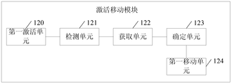
- FIG. 7 is a schematic structural diagram of an active mobility module according to an embodiment of the present application.
- FIG. 7b is a schematic structural diagram of another activation mobile module according to an embodiment of the present application.
- FIG. 8 is a schematic structural diagram of another vehicle control apparatus according to an embodiment of the present disclosure.
- FIG. 9 is a schematic structural diagram of still another vehicle control apparatus according to an embodiment of the present application.
- FIG. 1A shows a schematic diagram of an application scenario in accordance with some embodiments of the present application.
- the vehicle 110 in the application scenario may include a vehicle control device 111.
- the vehicle control device 111 may be a variety of in-vehicle smart devices such as a driving computer or a detachable mobile device built in the vehicle 110, which is not limited in this application.
- the vehicle control device 111 can communicate with the server 120 via the network 130.
- the vehicle control device 111 can acquire content such as route plan from the server 120.
- FIG. 1B is a flowchart of a vehicle control method according to an embodiment of the present application.
- the manner shown in FIG. 1B can be performed, for example, in the vehicle control device 111.
- the method can include the following steps:
- S100 Start a temporary parking mode of the first vehicle.
- the engine of the first vehicle is in a sleep mode
- the detection sensor of the first vehicle is in an on mode to detect whether a trigger feature is present within a preset range of the first vehicle.
- the triggering feature is used to trigger a fully automatic driving mode of the first vehicle.
- the first vehicle may be any motor vehicle, and when the first vehicle stops, the temporary parking mode of the first vehicle may be activated.
- the first vehicle is parked at a first pause position of the parking lot to activate a temporary parking mode of the first vehicle. Because of the pause position, the first vehicle will inevitably block other vehicles.
- the first vehicle can solve this problem by flexibly switching between the temporary parking mode and the fully automatic driving mode.
- the engine of the first vehicle is in a sleep mode while the detection sensor of the first vehicle is in an on mode.
- Detection sensors include, but are not limited to, infrared sensors, radars, cameras, and the like.
- the first vehicle is parked in a first pause position of the parking lot.
- the car park can be an open parking lot on the ground.
- the first vehicle may temporarily stop at the parking space near the occupied vehicle berth (ie, the pause position of the embodiment of the present application).
- the first vehicle is parked in a first pause position of the parking lot. Since the stopping time is relatively short, the first vehicle can temporarily stop at the first pause position for easy access, so as to avoid docking at the vehicle berth and difficult to drive out of the vehicle berth.
- the first vehicle When the first vehicle is parked in the first pause position, the first vehicle turns on the temporary parking mode after the driver leaves.
- the temporary parking mode in order to ensure the endurance ability and reduce the energy consumption of the first vehicle, the engine of the first vehicle is in the sleep mode, and only the detection sensor (such as an infrared sensor) is turned on.
- step S101 When the triggering feature in the first vehicle preset range is acquired by the detecting sensor, the fully-driving mode of the first vehicle is started.
- step S101 can start the fully automatic driving mode by activating the fully automatic driving system.
- the triggering feature includes any one or more of the following features:
- the second vehicle in the embodiment of the present application is any vehicle other than the first vehicle.
- the first vehicle starts the temporary parking mode, and detects whether there is a trigger feature in the first vehicle preset range by using the detection sensor of the first vehicle.
- the preset range may be the maximum range that the detection sensor can detect.
- the triggering feature may include, but is not limited to, an activation feature of the second vehicle within the preset range of the first vehicle periphery, an operational characteristic of the second vehicle, and a flashing feature, biometric, etc. of the second vehicle, The following describes the detection methods of the above trigger features separately.
- the detection feature of the activation feature of the second vehicle within the first vehicle preset range may be that the change in heat within the preset range is detected by the infrared sensor of the first vehicle. When the engine of the vehicle starts, it emits a certain amount of heat. When the infrared sensor of the first vehicle detects a change in heat, it indicates that there is an activation feature of the second vehicle.
- the detection feature of the activation feature of the second vehicle within the first vehicle preset range may be that the first vehicle may detect the activation feature of the second vehicle by the sound detection sensor. For example, if the sound detecting sensor detects the starting sound characteristic of the automobile, it is determined that there is a starting feature of the second vehicle.
- the detecting manner of the running characteristic of the second vehicle that is getting closer to the distance between the first vehicle within the first vehicle preset range may be that the preset range is detected by the radar of the first vehicle and the camera. Whether there is an operational characteristic of the second vehicle that is getting closer to the first vehicle. For example, the first vehicle detects that there is an obstacle closer to the first vehicle through the radar, and further, the first vehicle takes a picture in real time through the camera, and analyzes the picture to obtain the obstacle as a vehicle.
- the first vehicle may initiate the leveling of the sensor.
- the trigger feature is, for example, an operational feature or a biometric feature of the second vehicle that is gradually approaching the distance from the first vehicle within the preset range, but is not limited thereto.
- the plurality of detection sensors of the present application may include a first detection sensor and a second detection sensor.
- the first detecting sensor may include, for example, one or more of an infrared sensor, a radar sensor, a sound sensor, and a light sensor.
- the second sensor may include, for example, a camera, but is not limited thereto.
- step S100 may first activate the first detection sensor. In other words, step S100 turns off the second detecting sensor.
- step S101 can detect whether an object is close to the first vehicle by the first detecting sensor.
- step S101 may activate the second detecting sensor.
- step S101 can determine whether the object is a vehicle or a person by the second detecting sensor.
- step S101 determines, by the second detecting sensor, whether there are operating features or biometrics of the second vehicle that are gradually approaching within the preset range.
- the fully automatic driving mode of the first vehicle is initiated when it is determined that the operational feature or biometric meets the triggering feature.
- step S101 can save energy consumption of the first vehicle (eg, electric energy, etc.) by means of hierarchically starting the detection sensor.
- the method for detecting the flashing feature of the second vehicle in the preset range may be: collecting the image information of the current environment in real time through the camera of the first vehicle, and analyzing the image information to obtain the flashing of the second vehicle in the preset range. feature.
- the flashing feature can be used to describe the flash mode of the second vehicle.
- the range of the flash mode may include, for example, a double flash, a left turn flash, a right turn flash, and the like.
- the first vehicle can estimate the moving path of the second vehicle according to the flash mode.
- the first vehicle can be evaded according to the estimated movement path. For example, the first vehicle can move ahead according to the estimated movement path.
- detection sensors of the embodiments of the present application include, but are not limited to, the above-exemplified sensors.
- the trigger feature is used to trigger the first vehicle to initiate a fully automatic driving mode.
- the engine of the first vehicle is in an active mode.
- the first vehicle in the fully-automatic driving mode can rely on artificial intelligence, visual computing, radar, monitoring devices and global positioning system to cooperate, and can automatically and safely operate the first vehicle without any human active operation.
- the fully automatic driving mode may be the fully automatic driving mode of the L4.
- L4 is the fourth level of the Auto Carriage Technology Classification by the New Car Assessment Program (NHTSA) and the Society of Automotive Engineers (SAE), which is fully automated.
- NHSA New Car Assessment Program
- SAE Society of Automotive Engineers
- the first vehicle may be switched from the temporary parking mode to the fully automatic driving mode.
- step S102 In the fully automatic driving mode, activate the engine to move the first vehicle.
- step S102 may initiate a fully automatic driving mode of the first vehicle. For example, when it is detected that another second vehicle approaches or has a second vehicle activated, the automatic driving mode is immediately entered; for example, when another second vehicle flash is detected, the fully automatic driving mode is immediately entered.
- the first vehicle may also detect the presence of a biological proximity by an infrared sensor, and if a biological proximity is detected, activate the camera for identification. If there is a human approach (such as the presence of a facial feature), the prompt message is output immediately.
- the prompt information is used to prompt the user that the first vehicle can move. However, it needs to be indicated by the flashing lights of other vehicles, so that other users can indicate the avoidance to the first vehicle through the flashing lights of the vehicle if they need to drive through.
- the camera of the first vehicle detects that the user enters the car, and may also automatically enter the fully automatic driving mode, or the first vehicle waits for the flashing indication of the other vehicle to enter the fully automatic driving mode.
- the first vehicle activates the fully automatic driving mode and moves the first vehicle based on the fully automatic driving mode. For example, if the first vehicle detects that other second vehicles are getting closer or closer to other nearby vehicles, the first vehicle immediately enters the fully automatic driving mode.
- the first vehicle can invoke the camera to scan the scene environment through the fully automatic driving system, for example, using the camera to take a real-time photograph, and perform image analysis on the photographed image to determine whether the first vehicle blocks the travel path of the second vehicle of the other party.
- the first vehicle may call the radar to measure the width of the idle position around the first vehicle, and determine whether the first vehicle is clogging the travel path of the second vehicle according to the width of the second vehicle and the width of the idle position around the first vehicle.
- the first vehicle blocks the travel path of the second vehicle, the first vehicle is moved, thereby finding another pause position. If it is detected that the first vehicle does not block the traveling path of the second vehicle of the other party, the movement avoidance may be performed according to the second vehicle flashing feature of the other party until the second vehicle of the other party leaves the preset range that the first vehicle can perceive.
- the temporary parking mode is entered again.
- the first vehicle only needs to turn on the detection sensor, and the engine of the first vehicle is in the sleep mode, which can save the power consumption of the first vehicle.
- the first vehicle moves to a paused position in the ground open parking lot.
- the first vehicle can detect whether there is an idle vehicle berth within the preset range by the camera in the fully automatic driving mode. Specifically, the first vehicle captures an image in a preset range of the first vehicle through the camera, and analyzes the image to determine whether there is a feature of the free vehicle berth in the image, such as the feature of the idle vehicle berth is formed by lines Rectangular box.
- the first vehicle can automatically plan a path into the free vehicle berth and enter the free vehicle berth through the path. If the first vehicle finally enters the normal vehicle berth, the entire parking process is completed. At this time, the vehicle control device 111 can transmit the final parking position to the target user through the automatic driving system, and the target user can be the driver of the first vehicle.
- the automatic driving system can immediately send an alarm message to the target user for emergency processing.
- the vehicle can automatically switch between the temporary parking mode and the fully automatic driving mode, which not only can automatically control the vehicle movement, but also save power consumption.
- FIG. 2 is a flowchart of another vehicle control method according to an embodiment of the present application.
- the method shown in FIG. 2 can be performed, for example, in the vehicle control device 111.
- the vehicle control method of the embodiment of the present application includes the following steps:
- the parking lot may be an open parking lot on the ground.
- the camera on the first vehicle detects the current environment to determine whether there is an idle vehicle berth.
- the first vehicle may capture an image of the current environment through the camera, and analyze the image of the current environment to determine whether the current environment has characteristics of free vehicle berths, for example, features of the idle vehicle berth include pre-planned vehicles.
- the shape characteristics of the berth such as a rectangular frame planned by a white line, determine the presence of an idle vehicle berth if there is a feature of an idle vehicle berth. Further, it is also possible to detect whether there is an obstacle on the free vehicle berth by the radar of the first vehicle.
- the first vehicle detects that there is no free vehicle berth in the parking lot, that is, there is no feature of the idle vehicle berth in the current environment.
- the first vehicle acquires at least one idle location of the parking lot by analyzing an image of the current environment captured by the camera, and the idle location may be a location other than the vehicle berth in the parking lot.
- the first vehicle measures the size of the idle position by a radar or a camera, such as analyzing an image of the idle position captured by the camera, and the size of the idle position can be calculated.
- the first vehicle may select a first pause position from among the at least one idle position sought according to the size of the first vehicle (such as the length and width of the first vehicle), a selection criterion of the first pause position It may be that after the first pause position stops at the first vehicle, other vehicles can still pass by the first vehicle, that is, the distance between the first vehicle and the other parking vehicles is reserved to be sufficiently wide, such as greater than a preset threshold.
- the temporary parking mode of the first vehicle is started.
- the engine of the first vehicle is in a sleep mode, and the detection sensor of the first vehicle is in an on mode.
- steps S203 to S205 of the embodiment of the present application refer to the steps S100 to S102 of the embodiment of FIG. 1B, and details are not described herein again.
- the vehicle can automatically switch between the temporary parking mode and the fully automatic driving mode, which not only can automatically control the driving of the vehicle, but also save power consumption.
- FIG. 3 is a flowchart of still another vehicle control method according to an embodiment of the present application.
- the method illustrated in FIG. 3, for example, which may be performed in the vehicle control device 111, may include the following steps:
- steps S300 to S301 of the embodiment of the present application refer to the steps S100 to S101 of the embodiment of FIG. 1B, and details are not described herein again.
- the detection sensor when the first vehicle stops at the first pause position, the detection sensor may be periodically turned on to detect whether the triggering feature exists in the current environment. If there is a launch feature of the second vehicle in the current environment, then control initiates the fully automatic driving mode of the first vehicle.
- the activation feature may be acquired by a sound detecting sensor. For example, when the sound detecting sensor captures the sound feature of the vehicle start, step S302 determines that there is a launch feature of the second vehicle in the current environment.
- the activation feature may also be obtained by detecting heat by an infrared sensor.
- the triggering feature present in the current environment is an operating characteristic of the second vehicle that is closer to the distance between the first vehicle, then controlling the automatic driving mode of the first vehicle to be turned on. It should be noted that the distance between the second vehicle and the first vehicle can be detected by the camera or radar of the first vehicle.
- the first vehicle may photograph the current environment image through the camera, and analyze the environment image to determine whether the second vehicle exists. Further, the first vehicle detects whether the road width around the first vehicle is sufficient for the second vehicle to pass through the radar, and if the second vehicle passes, the first vehicle is determined to be on the travel path of the second vehicle.
- the first vehicle may determine the size of the second vehicle by using an image of the second vehicle photographed by the camera. In addition, the first vehicle may determine the width of the road on which the first vehicle is currently traveling through a radar or a camera.
- S304 Determine a second pause position according to a size of the second vehicle and a width of the traveling road, wherein stopping the first vehicle in the second pause position does not block the second vehicle from passing the Driving the road.
- the first vehicle may determine the second pause position according to the size of the second vehicle and the width of the current traveling road.
- the current road has a width of 8 meters and the second vehicle has a width of 5 meters.
- the width of the road occupied by the second pause position that the first vehicle can select should be at least less than or equal to 2.5 meters, since at least a spacing of 0.5 meters is required to facilitate the passage of the second vehicle.
- the first vehicle moves the first vehicle from the first pause position to the second pause position based on the fully automatic driving mode.
- the vehicle can automatically switch between the temporary parking mode and the fully automatic driving mode, which not only can automatically control the vehicle movement, but also save power consumption.
- FIG. 4 is a flowchart of still another vehicle control method according to an embodiment of the present application; and the method shown in FIG. 4 can be executed, for example, in the vehicle control device 111.
- the method can include the following steps:
- steps S400 to S401 of the embodiment of the present application refer to the steps S100 to S101 of the embodiment of FIG. 1B, and details are not described herein again.
- S402. Activate an engine to identify a flashing feature of the second vehicle based on the fully automatic driving mode of the first vehicle.
- the first vehicle control when it is detected that the trigger feature in the current environment includes the flash feature of the second vehicle, the first vehicle control turns on the fully automatic driving mode.
- the flashing feature of the second vehicle can be detected by the camera of the first vehicle.
- the camera captures an image within a preset range and analyzes the image to determine if there is a flash feature of the second vehicle.
- the flashing feature of the second vehicle may indicate that the second vehicle needs to pass the perimeter of the first vehicle, the first vehicle automatically identifies the flashing feature and moves according to the flashing feature, eg, the flashing feature indicates that the second vehicle requires Turning right, the first vehicle can measure whether the width of the right traveling road is sufficient for the second vehicle to turn right.
- FIG. 5 is a schematic flowchart diagram of still another vehicle control method according to an embodiment of the present application.
- the method shown in FIG. 5 can be performed, for example, in the vehicle control device 111.
- the vehicle control method of the embodiment of the present application includes the following steps:
- steps S500-S502 of the embodiment of the present application refer to the steps S100-S102 of the embodiment of FIG. 1B, and details are not described herein again.
- the first vehicle when the first vehicle is in the fully-automatic driving mode, the first vehicle may further detect whether there is an idle vehicle berth in the parking lot. For example, the first vehicle can capture an image of the current environment through the camera, and analyze the image to determine whether there is a feature of the free vehicle berth in the current environment. If there are features of idle vehicle berths, then there are free vehicle berths.
- the first vehicle can scan the surrounding environment for free vehicle berths while driving through the fully automatic driving system.
- the path of the first vehicle's current location to the idle vehicle berth may be planned by the automatic driving system.
- the first vehicle may send an identification of the free vehicle berth and the location of the first vehicle to the server 120, and the server 120 plans a path for the first vehicle to arrive at the free vehicle berth.
- the free vehicle berth may be entered according to the route.
- the automatic driving system transmits the position of the idle vehicle berth to the target user.
- the target user may be a user bound to the first vehicle, such as a mobile terminal of the driver of the first vehicle, in such a manner that the driver can be made aware of the specific location of the first vehicle.
- the first vehicle's automatic driving system and all of the detection sensors are turned off.
- the first vehicle when the first vehicle detects that there is still no idle vehicle berth, it switches from the fully automatic driving mode to the temporary parking mode again, that is, starts the temporary parking mode of the first vehicle again, and simultaneously opens the first vehicle.
- the detection sensor continues to detect if there is a trigger feature in the current environment.
- FIG. 6 is a schematic structural diagram of a vehicle control device according to an embodiment of the present disclosure. As shown in the figure, a vehicle control device according to an embodiment of the present application includes:
- a first starting module 10 configured to start a temporary parking mode of the first vehicle, in the temporary parking mode, the engine of the first vehicle is in a sleep mode, and the detection sensor of the first vehicle is in an open mode;
- the first obtaining module 11 is configured to acquire a trigger feature in the first vehicle preset range, where the trigger feature is used to trigger the first vehicle to start a fully automatic driving mode;
- the triggering feature includes any one or more of the following features:
- the second vehicle in the embodiment of the present application is any vehicle other than the first vehicle.
- the mobile module 12 is activated for activating the engine, in which the first vehicle is moved.
- the activation mobile module 12 includes a first activation unit 120, a detection unit 121, an acquisition unit 122, a determination unit 123, and a first mobile unit 124;
- the detecting unit 121 is configured to detect, according to the fully-automatic driving mode of the first vehicle, whether the first vehicle is on a driving path of the second vehicle;
- the acquiring unit 122 is configured to acquire a size of the second vehicle and a width of the first vehicle and a current traveling road if the first vehicle is on a traveling path of the second vehicle;
- a determining unit 123 configured to determine a second pause position according to a size of the second vehicle and a width of the traveling road, wherein the stopping of the first vehicle in the second pause position does not block the second Passing the vehicle through the road;
- the first moving unit 124 is configured to move the first vehicle to a second pause position.
- the activation mobile module includes a second activation unit 125, an identification unit 126, and a second mobile unit 127;
- a second activation unit 125 for activating the engine
- the identifying unit 126 is configured to identify a flashing feature of the second vehicle based on the fully-automatic driving mode of the first vehicle;
- the second moving unit 127 is configured to move the first vehicle according to the flashing feature of the second vehicle to avoid the second vehicle.
- FIG. 8 is a schematic structural diagram of another vehicle control apparatus according to an embodiment of the present application.
- the vehicle control apparatus of the embodiment of the present application includes a first startup module 20, a first acquisition module 21, and an activation movement. Module 22;
- the vehicle control device of the embodiment of the present application may further include a first detecting module 23, a second acquiring module 24, and a selecting module 25;
- the first detecting module 23 is configured to detect, when the first vehicle arrives at the parking lot, whether the parking lot has an idle vehicle berth;
- the second obtaining module 24 is configured to acquire an idle location of the parking lot if the parking lot does not have an idle vehicle berth;
- the selection module 25 is configured to select a first pause position to be docked from the idle positions according to the size of the first vehicle.
- the vehicle control apparatus of the embodiment of the present application may further include a second detecting module 26, a planning module 27, and a second starting module 28;
- a second detecting module 26 configured to detect, according to the fully-automatic driving mode of the first vehicle, whether the parking lot has an idle vehicle berth;
- a planning module 27 if there is an idle vehicle berth, planning a path of the current location of the first vehicle to the idle vehicle berth, and controlling the first vehicle to enter the idle according to the path Vehicle berth
- the second starting module 28 is configured to activate the temporary parking mode of the first vehicle if there is no idle vehicle berth.
- the vehicle control apparatus 1000 may include at least one processor 1001, such as a CPU, at least one network interface 1004, a user interface 1003, a memory 1005, and at least one communication bus 1002.
- the communication bus 1002 is used to implement connection communication between these components.
- the user can communicate with the vehicle control device by calling the user interface 1003, which can include a button, a touch screen, and the like.
- the network interface 1004 can include a standard wired interface, a wireless interface (such as a WI-FI interface).
- the memory 1005 may be a high speed RAM memory or a non-volatile memory such as at least one disk memory.
- the memory 1005 may also be at least one storage device located remotely from the aforementioned processor 1001. As shown in FIG. 8, an operating system, a network communication module, a user interface module, and a data processing application may be included in the memory 1005 as a computer storage medium.
- the processor 1001 can be used to call a data processing application stored in the memory 1005, and specifically perform the following operations:
- the detection sensor of the first vehicle is in an on mode to detect a preset range of the first vehicle Whether there is a trigger feature inside;
- the engine is activated to move the first vehicle.
- a first pause position of the stop is selected from the idle positions according to the size of the first vehicle.
- the triggering feature includes any one or more of the following features:
- the performing, in the fully-automatic driving mode, moving the first vehicle specifically includes:
- moving the first vehicle includes:
- the vehicle control device 1000 may also perform the following operations:
- the temporary parking mode of the first vehicle is initiated if there are no free vehicle berths.
Landscapes
- Engineering & Computer Science (AREA)
- Mechanical Engineering (AREA)
- Transportation (AREA)
- Automation & Control Theory (AREA)
- Combustion & Propulsion (AREA)
- Chemical & Material Sciences (AREA)
- Physics & Mathematics (AREA)
- General Physics & Mathematics (AREA)
- Human Computer Interaction (AREA)
- Theoretical Computer Science (AREA)
- Multimedia (AREA)
- Mathematical Physics (AREA)
- Traffic Control Systems (AREA)
- Control Of Driving Devices And Active Controlling Of Vehicle (AREA)
- Radar, Positioning & Navigation (AREA)
- Remote Sensing (AREA)
Abstract
Description
Claims (31)
- 一种车辆控制方法,应用于车辆控制装置,所述方法包括:启动第一车辆的暂时停泊模式,在所述暂时停泊模式下,所述第一车辆的发动机处于休眠模式,所述第一车辆的检测传感器处于开启模式;当通过所述检测传感器获取到所述第一车辆预设范围内的触发特征时,启动所述第一车辆的全自动驾驶模式;在所述全自动驾驶模式下,激活发动机,移动所述第一车辆。
- 如权利要求1所述的方法,进一步包括:当第一车辆到达停车场时,检测所述停车场是否存在空闲的车辆泊位;当检测到所述停车场不存在空闲的车辆泊位时,获取所述停车场的空闲位置;根据所述第一车辆的大小,从所述空闲位置中选择停靠的第一暂停位置,移动所述第一车辆到所述第一暂停位置以便执行所述启动第一车辆的所述暂时停泊模式的操作。
- 如权利要求1所述的方法,其中,所述触发特征包括以下特征中的任意一种或者多种:所述预设范围内第二车辆的启动特征;所述预设范围内与所述第一车辆的距离逐渐靠近的第二车辆的运行特征;所述预设范围内第二车辆的闪灯特征。
- 如权利要求1所述的方法,其中,所述移动所述第一车辆,包括:检测所述第一车辆是否在第二车辆的行驶路径上;当检测到所述第一车辆在所述第二车辆的行驶路径上时,获取所述第二车辆的大小以及所述第一车辆与当前所在行驶道路的宽度;根据所述第二车辆的大小以及所述行驶道路的宽度,确定第二暂停位置,所述第二暂停位置容纳所述第一车辆并使所述第一车辆不会阻挡所述第二车辆通过所述行驶道路;将所述第一车辆移动至所述第二暂停位置。
- 如权利要求1所述的方法,其中,所述触发特征包含第二车辆的闪灯特征;所述移动所述第一车辆,包括:根据所述闪灯特征预估所述第二车辆的移动路径;根据所述移动路径移动所述第一车辆,以避让所述第二车辆。
- 如权利要求1所述的方法,进一步包括:检测所述停车场是否存在空闲的车辆泊位;当检测到存在空闲的车辆泊位时,规划所述第一车辆的当前位置到达所述空闲的车辆泊位的路径;根据所述路径,控制所述第一车辆驶入所述空闲的车辆泊位;当检测到不存在空闲的车辆泊位时,启动所述第一车辆的所述暂时停泊模式。
- 如权利要求1所述的方法,进一步包括:通过所述第一车辆的检测传感器检测到有人员靠近时,输出语音提示信息,所述语音提示信息用于提示所述第一车辆能够移动避让。
- 如权利要求4所述的方法,其中,所述检测所述第一车辆是否在第二车辆的行驶路径上,包括:通过摄像头拍摄图像;对所拍摄的图像进行分析,并确定所述第一车辆是否堵塞所述第二车辆的行使路径。
- 如权利要求8所述的方法,其中,所述确定所述第一车辆是否堵塞所述第二车辆的行驶路径,包括:通过雷达测量所述第一车辆周围空闲位置的宽度;根据第二车辆的宽度和第一车辆周围空闲位置的宽度,确定该第一车辆是否堵塞第二车辆的行驶路径。
- 如权利要求6所述的方法,其中,所述检测所述停车场是否存在空闲的车辆泊位,包括:通过摄像头拍摄当前环境的图像;对该当前环境的图像进行分析,确定该当前环境是否存在空闲的车辆泊位的特征。
- 如权利要求10所述的方法,其中,所述检测所述停车场是否存在空闲的车辆泊位,还包括:当确定存在所述空闲的车辆泊位的特征时,通过雷达检测所述空闲的车辆泊位是否存在障碍物。
- 如权利要求10所述的方法,其中,所述当前环境的图像包括所述停车场出口的图像;所述对该当前环境的图像进行分析,确定该当前环境是否存在空闲的车辆泊位的特征,包括:对所述停车场出口的图像进行分析,以便确定是否有车辆离开所述停车场;当确定有车辆离开所述停车场时,确定所述当前环境存在空闲的车辆泊位的特征。
- 如权利要求6所述的方法,其中,所述规划所述第一车辆的当前位置到达所述空闲的车辆泊位的路径,包括:将空闲的车辆泊位的标识以及第一车辆的位置发送至服务器,以便服务器规划该第一车辆到达空闲的车辆泊位的路径;从所述服务器获取所述路径。
- 如权利要求1所述的方法,其中,所述启动所述第一车辆的暂时停泊模式,包括:关闭所述第一车辆的多个检测传感器中的第二检测传感器,处于开启模式的所述检测传感器为所述多个检测传感器中的第一检测传感器;启动所述第一车辆的全自动驾驶模式,包括:当通过所述第一检测传感器检测到有物体靠近所述第一车辆时,启动所述第二检测传感器;通过所述第二检测传感器获取所述物体的运行特征或者生物特征;当确定所述物体的运行特征或者生物特征符合所述触发特征时,启动所述第一车辆的全自动驾驶模式。
- 如权利要求1所述的方法,进一步包括:当检测到所述第一车辆发生碰撞情况时,向与所述第一车辆关联的终端设备发送对碰撞情况的通知消息。
- 一种车辆控制装置,包括:处理器和存储器;所述存储器中存储有计算机可读指令,可以使所述处理器:启动第一车辆的暂时停泊模式,在所述暂时停泊模式下,所述第一车辆的 发动机处于休眠模式,所述第一车辆的检测传感器处于开启模式;当通过所述检测传感器获取到所述第一车辆预设范围内的触发特征时,启动所述第一车辆的全自动驾驶模式;在所述全自动驾驶模式下,激活发动机,移动所述第一车辆。
- 如权利要求16所述的装置,其中,所述处理器进一步执行所述计算机可读指令,用于:当第一车辆到达停车场时,检测所述停车场是否存在空闲的车辆泊位;当检测到所述停车场不存在空闲的车辆泊位时,获取所述停车场的空闲位置;根据所述第一车辆的大小,从所述空闲位置中选择停靠的第一暂停位置,移动所述第一车辆到所述第一暂停位置以便执行所述启动第一车辆的所述暂时停泊模式的操作。
- 如权利要求16所述的装置,其中,所述触发特征包括以下特征中的任意一种或者多种:所述预设范围内第二车辆的启动特征;所述预设范围内与所述第一车辆的距离逐渐靠近的第二车辆的运行特征;所述预设范围内第二车辆的闪灯特征。
- 如权利要求16所述的装置,其中,所述处理器进一步执行所述计算机可读指令,用于:检测所述第一车辆是否在第二车辆的行驶路径上;当检测到所述第一车辆在所述第二车辆的行驶路径上时,获取所述第二车辆的大小以及所述第一车辆与当前所在行驶道路的宽度;根据所述第二车辆的大小以及所述行驶道路的宽度,确定第二暂停位置,所述第二暂停位置容纳所述第一车辆并使所述第一车辆不会阻挡所述第二车辆通过所述行驶道路;将所述第一车辆移动至所述第二暂停位置。
- 如权利要求16所述的装置,其中,所述处理器进一步执行所述计算机可读指令,用于:根据所述闪灯特征预估所述第二车辆的移动路径;根据所述移动路径移动所述第一车辆,以避让所述第二车辆。
- 如权利要求16所述的装置,其中,所述处理器进一步执行所述计算机可读指令,用于:检测所述停车场是否存在空闲的车辆泊位;当检测到存在空闲的车辆泊位时,规划所述第一车辆的当前位置到达所述空闲的车辆泊位的路径;根据所述路径,控制所述第一车辆驶入所述空闲的车辆泊位;当检测到不存在空闲的车辆泊位时,启动所述第一车辆的所述暂时停泊模式。
- 如权利要求16所述的装置,其中,所述处理器进一步执行所述计算机可读指令,用于:通过所述第一车辆的检测传感器检测到有人员靠近时,输出语音提示信息,所述语音提示信息用于提示所述第一车辆能够移动避让。
- 如权利要求19所述的装置,其中,所述处理器进一步执行所述计算机可读指令,用于:通过摄像头拍摄图像;对所拍摄的图像进行分析,并确定所述第一车辆是否堵塞所述第二车辆的行使路径。
- 如权利要求23所述的装置,其中,所述处理器进一步执行所述计算机可读指令,用于:通过雷达测量所述第一车辆周围空闲位置的宽度;根据第二车辆的宽度和第一车辆周围空闲位置的宽度,确定该第一车辆是否堵塞第二车辆的行驶路径。
- 如权利要求21所述的装置,其中,所述处理器进一步执行所述计算机可读指令,用于:通过摄像头拍摄当前环境的图像;对该当前环境的图像进行分析,确定该当前环境是否存在空闲的车辆泊位的特征。
- 如权利要求25所述的装置,其中,所述处理器进一步执行所述计算机 可读指令,用于:当确定存在所述空闲的车辆泊位的特征时,通过雷达检测所述空闲的车辆泊位是否存在障碍物。
- 如权利要求25所述的装置,其中,所述当前环境的图像包括所述停车场出口的图像;所述处理器进一步执行所述计算机可读指令,用于:对所述停车场出口的图像进行分析,以便确定是否有车辆离开所述停车场;当确定有车辆离开所述停车场时,确定所述当前环境存在空闲的车辆泊位的特征。
- 如权利要求21所述的装置,其中,所述处理器进一步执行所述计算机可读指令,用于:将空闲的车辆泊位的标识以及第一车辆的位置发送至服务器,以便服务器规划该第一车辆到达空闲的车辆泊位的路径;从所述服务器获取所述路径。
- 如权利要求16所述的装置,其中,所述处理器进一步执行所述计算机可读指令,用于:关闭所述第一车辆的多个检测传感器中的第二检测传感器,处于开启模式的所述检测传感器为所述多个检测传感器中的第一检测传感器;通过所述第一检测传感器检测到有物体靠近所述第一车辆时,启动所述第二检测传感器;通过所述第二检测传感器获取所述物体的运行特征或者生物特征;当确定所述物体的运行特征或者生物特征符合所述触发特征时,启动所述第一车辆的全自动驾驶模式。
- 如权利要求16所述的装置,其中所述处理器进一步执行所述计算机可读指令,用于:当检测到所述第一车辆发生碰撞情况时,向与所述第一车辆关联的终端设备发送对碰撞情况的通知消息。
- 一种非易失性存储介质,存储有一个或多个程序,所述一个或多个程序包括指令,所述指令当由车辆控制装置执行时,使得所述车辆控制装置执行权利要求1-15中任一项所述方法的指令。
Priority Applications (4)
| Application Number | Priority Date | Filing Date | Title |
|---|---|---|---|
| EP18770324.4A EP3604068B1 (en) | 2017-03-21 | 2018-03-15 | Vehicle control method, device and storage medium |
| JP2019549464A JP7118493B2 (ja) | 2017-03-21 | 2018-03-15 | 車両制御方法、装置及び記憶媒体 |
| KR1020197018151A KR20190085545A (ko) | 2017-03-21 | 2018-03-15 | 차량 제어 방법 및 장치, 그리고 저장 매체 |
| US16/436,589 US11225246B2 (en) | 2017-03-21 | 2019-06-10 | Vehicle control method and apparatus, and storage medium |
Applications Claiming Priority (2)
| Application Number | Priority Date | Filing Date | Title |
|---|---|---|---|
| CN201710168826.2A CN108297870B (zh) | 2017-03-21 | 2017-03-21 | 一种车辆控制方法及装置 |
| CN201710168826.2 | 2017-03-21 |
Related Child Applications (1)
| Application Number | Title | Priority Date | Filing Date |
|---|---|---|---|
| US16/436,589 Continuation US11225246B2 (en) | 2017-03-21 | 2019-06-10 | Vehicle control method and apparatus, and storage medium |
Publications (1)
| Publication Number | Publication Date |
|---|---|
| WO2018171506A1 true WO2018171506A1 (zh) | 2018-09-27 |
Family
ID=62872078
Family Applications (1)
| Application Number | Title | Priority Date | Filing Date |
|---|---|---|---|
| PCT/CN2018/079149 Ceased WO2018171506A1 (zh) | 2017-03-21 | 2018-03-15 | 一种车辆控制方法、装置及存储介质 |
Country Status (6)
| Country | Link |
|---|---|
| US (1) | US11225246B2 (zh) |
| EP (1) | EP3604068B1 (zh) |
| JP (1) | JP7118493B2 (zh) |
| KR (1) | KR20190085545A (zh) |
| CN (2) | CN110949392B (zh) |
| WO (1) | WO2018171506A1 (zh) |
Cited By (3)
| Publication number | Priority date | Publication date | Assignee | Title |
|---|---|---|---|---|
| JP2020104840A (ja) * | 2018-11-26 | 2020-07-09 | トヨタ リサーチ インスティテュート,インコーポレイティド | ビークルの自律運転のための互いに異なる運転モードから選択するためのシステム及び方法 |
| CN111636735A (zh) * | 2020-05-27 | 2020-09-08 | 无锡科技职业学院 | 一种智能立体车库管理系统 |
| JP2022181254A (ja) * | 2021-05-26 | 2022-12-08 | トヨタ自動車株式会社 | リモート駐車装置 |
Families Citing this family (21)
| Publication number | Priority date | Publication date | Assignee | Title |
|---|---|---|---|---|
| KR102705149B1 (ko) * | 2018-12-06 | 2024-09-12 | 현대자동차주식회사 | 자율 발렛 주차를 지원하는 시스템 및 방법, 그리고 이를 위한 인프라 및 차량 |
| US10589720B1 (en) | 2019-06-07 | 2020-03-17 | Capital One Services, Llc | Automated system for car access in retail environment |
| US10591576B1 (en) * | 2019-06-07 | 2020-03-17 | Capital One Services, Llc | Automated system for vehicle tracking |
| US10682980B1 (en) | 2019-06-07 | 2020-06-16 | Capital One Services, Llc | Systems and methods for test driving cars with limited human interaction |
| US10900801B2 (en) | 2019-06-07 | 2021-01-26 | Capital One Services, Llc | Augmented reality directions utilizing physical reference markers |
| JP7248124B2 (ja) * | 2019-07-19 | 2023-03-29 | 株式会社デンソー | 駐車支援システム及び管理装置 |
| DE102019212791A1 (de) * | 2019-08-27 | 2021-03-04 | Ford Global Technologies, Llc | Verfahren zur Durchführung von automatischem Valet-Parken |
| US12131641B2 (en) | 2020-06-05 | 2024-10-29 | Capital One Services, Llc | Systems and methods for providing an autonomous vehicle vendor lot |
| US11866038B2 (en) | 2020-08-18 | 2024-01-09 | Toyota Motor North America, Inc. | Situation-specific transport power allocation |
| CN112572418A (zh) | 2020-12-15 | 2021-03-30 | 北京百度网讯科技有限公司 | 一种无人驾驶车辆的控制方法、装置及电子设备 |
| JP7638586B2 (ja) * | 2021-03-01 | 2025-03-04 | パナソニックオートモーティブシステムズ株式会社 | 駐車支援装置および駐車支援方法 |
| CN113386608B (zh) * | 2021-06-30 | 2023-05-12 | 钟求明 | 基于自动驾驶汽车的充电统筹排序方法及智能充电站 |
| EP4350661A4 (en) * | 2021-06-30 | 2024-10-23 | Huawei Technologies Co., Ltd. | VEHICLE CONTROL METHOD AND APPARATUS AND SYSTEM |
| KR20230064701A (ko) * | 2021-11-03 | 2023-05-11 | 현대자동차주식회사 | 자율 주행 차량, 그를 원격 제어하는 관제 시스템 및 그 방법 |
| CN116363893B (zh) * | 2021-12-27 | 2024-10-11 | 比亚迪股份有限公司 | 停车控制方法、装置、设备及计算机可读存储介质 |
| US11999344B2 (en) * | 2022-02-20 | 2024-06-04 | Beijing Jingdong Qianshi Technology Co., Ltd. | System and method for selecting an intermediate parking goal in autonomous delivery |
| US20230286584A1 (en) * | 2022-03-08 | 2023-09-14 | Ford Global Technologies, Llc | Method for operating a motor vehicle with a parking assistant |
| DE102022203272A1 (de) * | 2022-04-01 | 2023-10-05 | Robert Bosch Gesellschaft mit beschränkter Haftung | Verfahren zum Planen eines AVP-Vorgangs |
| JP7643405B2 (ja) | 2022-06-28 | 2025-03-11 | トヨタ自動車株式会社 | 自動バレー駐車管理システム及び自動バレー駐車管理方法 |
| CN118046891A (zh) * | 2022-11-16 | 2024-05-17 | 华为技术有限公司 | 一种泊车方法及装置 |
| TWI890269B (zh) * | 2024-01-11 | 2025-07-11 | 大陸商富士康科技集團有限公司 | 車輛控制方法、伺服器、車輛及存儲介質 |
Citations (8)
| Publication number | Priority date | Publication date | Assignee | Title |
|---|---|---|---|---|
| CN101412401A (zh) * | 2007-10-17 | 2009-04-22 | 罗伯特·博世有限公司 | 用于泊车支持的控制装置和方法 |
| JP2011016401A (ja) * | 2009-07-07 | 2011-01-27 | Toyota Industries Corp | 駐車支援装置 |
| US20130315443A1 (en) * | 2012-05-25 | 2013-11-28 | Mando Corporation | Vehicular parking control system and vehicular parking control method using the same |
| CN103700277A (zh) * | 2013-12-11 | 2014-04-02 | 安徽锐通信息技术有限公司 | 停车位置记录系统、移动终端和停车位置记录方法 |
| CN104742881A (zh) * | 2015-04-15 | 2015-07-01 | 百度在线网络技术(北京)有限公司 | 自动泊车系统和方法 |
| CN106043305A (zh) * | 2015-04-01 | 2016-10-26 | 株式会社万都 | 车辆离开支持系统及方法 |
| US20170028989A1 (en) * | 2015-07-29 | 2017-02-02 | Meera Thillainatesan | Temporary Parking for Motorized Vehicles |
| CN108010373A (zh) * | 2017-09-15 | 2018-05-08 | 路特迩科技(杭州)有限公司 | 基于泊位状态信息的泊位服务与管理系统及方法 |
Family Cites Families (34)
| Publication number | Priority date | Publication date | Assignee | Title |
|---|---|---|---|---|
| JPS6437661A (en) * | 1987-08-04 | 1989-02-08 | Mitsubishi Heavy Ind Ltd | Parking zone control system |
| JP4147648B2 (ja) * | 1998-11-10 | 2008-09-10 | 日産自動車株式会社 | 車両用歩行者検知システム |
| US7026954B2 (en) * | 2003-06-10 | 2006-04-11 | Bellsouth Intellectual Property Corporation | Automated parking director systems and related methods |
| JP2008299415A (ja) | 2007-05-29 | 2008-12-11 | Nichizou Tec:Kk | 駐車場管理システムおよび車両移動方向検出センサ |
| US8948990B2 (en) * | 2010-06-25 | 2015-02-03 | Nissan Motor Co., Ltd. | Parking assist control apparatus and control method |
| JP5565303B2 (ja) * | 2010-12-27 | 2014-08-06 | トヨタ自動車株式会社 | 運転支援装置及び運転支援方法 |
| KR20140051615A (ko) * | 2012-10-23 | 2014-05-02 | 현대자동차주식회사 | 비주차구역의 주차 지원 장치 및 방법 |
| JP5790696B2 (ja) * | 2013-04-10 | 2015-10-07 | トヨタ自動車株式会社 | 車両遠隔操作システム及び車載機 |
| US9102330B2 (en) * | 2013-07-31 | 2015-08-11 | Here Global B.V. | Method and apparatus for causing an adjustment in parking position for vehicles |
| DE102013215208B4 (de) * | 2013-08-02 | 2026-03-26 | Ford Global Technologies, Llc | Verfahren und Vorrichtung zur Einparkunterstützung eines Fahrzeuges |
| DE102013215260A1 (de) * | 2013-08-02 | 2015-02-05 | Ford Global Technologies, Llc | Verfahren und Vorrichtung zum Betreiben eines Kraftfahrzeuges |
| DE102014001554B4 (de) * | 2014-02-05 | 2016-07-14 | Audi Ag | Verfahren zum automatischen Parken eines Fahrzeugs und zugehörige Steuerungseinrichtung |
| CN104057950B (zh) * | 2014-05-21 | 2016-04-27 | 重庆长安汽车股份有限公司 | 一种全自动泊车系统 |
| JP6260462B2 (ja) * | 2014-06-10 | 2018-01-17 | 株式会社デンソー | 運転支援装置 |
| DE102014211557A1 (de) * | 2014-06-17 | 2015-12-31 | Robert Bosch Gmbh | Valet Parking Verfahren und System |
| JP6022517B2 (ja) * | 2014-09-12 | 2016-11-09 | アイシン精機株式会社 | 車両の制御装置 |
| KR101610526B1 (ko) | 2014-10-21 | 2016-04-07 | 현대자동차주식회사 | 차량의 주차 제어 장치 및 방법, 그리고 차량 시스템 |
| DE102014224454B4 (de) * | 2014-11-28 | 2021-06-10 | Robert Bosch Gmbh | Verfahren zum Betrieb eines Fahrzeugs |
| DE102014224601A1 (de) * | 2014-12-02 | 2016-06-02 | Robert Bosch Gmbh | Vorrichtung und Verfahren zum Betreiben eines Parkplatzes |
| JP2016126607A (ja) * | 2015-01-06 | 2016-07-11 | 株式会社デンソー | 当て逃げ車両特定装置 |
| DE102015200044B4 (de) * | 2015-01-06 | 2022-07-07 | Ford Global Technologies, Llc | Verfahren und Vorrichtung zur Unterstützung eines Manövriervorganges eines Kraftfahrzeugs |
| JP6350312B2 (ja) * | 2015-01-29 | 2018-07-04 | 株式会社デンソー | 非接触充電駐車支援装置 |
| US9139199B2 (en) * | 2015-02-01 | 2015-09-22 | Thomas Danaher Harvey | Methods for dense parking of remotely controlled or autonomous vehicles |
| JP2016173637A (ja) * | 2015-03-16 | 2016-09-29 | パナソニックIpマネジメント株式会社 | 車両制御装置及び車両 |
| KR20160114486A (ko) | 2015-03-24 | 2016-10-05 | 엘지전자 주식회사 | 이동단말기 및 이동 단말기의 제어방법 |
| EP3072710B1 (en) | 2015-03-24 | 2018-03-28 | LG Electronics Inc. | Vehicle, mobile terminal and method for controlling the same |
| JP2016184200A (ja) * | 2015-03-25 | 2016-10-20 | 住友電気工業株式会社 | 歩行者接近報知装置、歩行者接近報知システム、コンピュータプログラム及び歩行者接近報知方法 |
| CN104691544B (zh) * | 2015-04-03 | 2017-03-01 | 重庆瓦力仪器有限公司 | 全自动泊车系统及其泊车方法 |
| KR101663511B1 (ko) | 2015-04-30 | 2016-10-14 | 엘지전자 주식회사 | 차량 운전 보조 장치, 차량 운전 보조 장치의 제어 방법 및 차량 |
| DE102015212581A1 (de) * | 2015-07-06 | 2017-01-12 | Robert Bosch Gmbh | Verfahren zur Fahrerassistenz und Fahrerassistenzsystem |
| US10747234B1 (en) * | 2016-01-22 | 2020-08-18 | State Farm Mutual Automobile Insurance Company | Method and system for enhancing the functionality of a vehicle |
| CN105869098B (zh) * | 2016-04-06 | 2020-02-07 | 北京小米移动软件有限公司 | 车辆控制方法和装置 |
| CN106043282A (zh) * | 2016-07-26 | 2016-10-26 | 浙江吉利控股集团有限公司 | 一种用于车辆的全自动泊车系统及其控制方法 |
| CN106274898B (zh) * | 2016-09-26 | 2018-11-27 | 江苏天安智联科技股份有限公司 | 一种车载遥控泊车设备及其系统 |
-
2017
- 2017-03-21 CN CN201911275678.XA patent/CN110949392B/zh active Active
- 2017-03-21 CN CN201710168826.2A patent/CN108297870B/zh active Active
-
2018
- 2018-03-15 WO PCT/CN2018/079149 patent/WO2018171506A1/zh not_active Ceased
- 2018-03-15 JP JP2019549464A patent/JP7118493B2/ja active Active
- 2018-03-15 KR KR1020197018151A patent/KR20190085545A/ko not_active Ceased
- 2018-03-15 EP EP18770324.4A patent/EP3604068B1/en active Active
-
2019
- 2019-06-10 US US16/436,589 patent/US11225246B2/en active Active
Patent Citations (8)
| Publication number | Priority date | Publication date | Assignee | Title |
|---|---|---|---|---|
| CN101412401A (zh) * | 2007-10-17 | 2009-04-22 | 罗伯特·博世有限公司 | 用于泊车支持的控制装置和方法 |
| JP2011016401A (ja) * | 2009-07-07 | 2011-01-27 | Toyota Industries Corp | 駐車支援装置 |
| US20130315443A1 (en) * | 2012-05-25 | 2013-11-28 | Mando Corporation | Vehicular parking control system and vehicular parking control method using the same |
| CN103700277A (zh) * | 2013-12-11 | 2014-04-02 | 安徽锐通信息技术有限公司 | 停车位置记录系统、移动终端和停车位置记录方法 |
| CN106043305A (zh) * | 2015-04-01 | 2016-10-26 | 株式会社万都 | 车辆离开支持系统及方法 |
| CN104742881A (zh) * | 2015-04-15 | 2015-07-01 | 百度在线网络技术(北京)有限公司 | 自动泊车系统和方法 |
| US20170028989A1 (en) * | 2015-07-29 | 2017-02-02 | Meera Thillainatesan | Temporary Parking for Motorized Vehicles |
| CN108010373A (zh) * | 2017-09-15 | 2018-05-08 | 路特迩科技(杭州)有限公司 | 基于泊位状态信息的泊位服务与管理系统及方法 |
Non-Patent Citations (1)
| Title |
|---|
| See also references of EP3604068A4 * |
Cited By (5)
| Publication number | Priority date | Publication date | Assignee | Title |
|---|---|---|---|---|
| JP2020104840A (ja) * | 2018-11-26 | 2020-07-09 | トヨタ リサーチ インスティテュート,インコーポレイティド | ビークルの自律運転のための互いに異なる運転モードから選択するためのシステム及び方法 |
| JP7399691B2 (ja) | 2018-11-26 | 2023-12-18 | トヨタ リサーチ インスティテュート,インコーポレイティド | ビークルの自律運転のための互いに異なる運転モードから選択するためのシステム及び方法 |
| CN111636735A (zh) * | 2020-05-27 | 2020-09-08 | 无锡科技职业学院 | 一种智能立体车库管理系统 |
| JP2022181254A (ja) * | 2021-05-26 | 2022-12-08 | トヨタ自動車株式会社 | リモート駐車装置 |
| JP7663022B2 (ja) | 2021-05-26 | 2025-04-16 | トヨタ自動車株式会社 | リモート駐車装置 |
Also Published As
| Publication number | Publication date |
|---|---|
| CN108297870A (zh) | 2018-07-20 |
| CN110949392A (zh) | 2020-04-03 |
| JP7118493B2 (ja) | 2022-08-16 |
| KR20190085545A (ko) | 2019-07-18 |
| CN110949392B (zh) | 2021-04-30 |
| EP3604068A1 (en) | 2020-02-05 |
| CN108297870B (zh) | 2020-01-14 |
| US11225246B2 (en) | 2022-01-18 |
| EP3604068B1 (en) | 2022-05-04 |
| US20190308616A1 (en) | 2019-10-10 |
| JP2020511353A (ja) | 2020-04-16 |
| EP3604068A4 (en) | 2020-03-11 |
Similar Documents
| Publication | Publication Date | Title |
|---|---|---|
| WO2018171506A1 (zh) | 一种车辆控制方法、装置及存储介质 | |
| US10643472B2 (en) | Monitor apparatus and monitor system | |
| US10852741B2 (en) | Using cameras for detecting objects near a vehicle | |
| CN109067925B (zh) | 一种远程遥控的泊车方法和系统 | |
| CN109501805B (zh) | 自动驾驶车辆和用于自动驾驶车辆的控制方法 | |
| US20220135024A1 (en) | Parking assist system | |
| CN110430401A (zh) | 车辆盲区预警方法、预警装置、mec平台和存储介质 | |
| CN105869098A (zh) | 车辆控制方法和装置 | |
| US10836392B2 (en) | Vehicle situation determination device and vehicle situation determination method | |
| CN112172792A (zh) | 固定车位泊车方法、装置、车辆及存储介质 | |
| CN115230712A (zh) | 监控模式启动方法、装置、车辆及介质 | |
| CN116001773A (zh) | 自动泊车系统、自动泊车系统的控制方法以及存储介质 | |
| JP6679938B2 (ja) | 自動運転車両 | |
| JP7310903B2 (ja) | 駐車支援装置、及び駐車支援方法 | |
| CN115387692B (zh) | 一种车门控制方法、车辆及存储介质 | |
| US20220281440A1 (en) | Automated valet parking system and control method of automated valet parking system | |
| CN119251917B (zh) | Etc交互控制方法及装置 | |
| CN107463886B (zh) | 一种双闪识别以及车辆避障的方法和系统 | |
| JP7582001B2 (ja) | 車両運行装置 | |
| CN117950394A (zh) | 机器人的控制方法、装置、机器人及存储介质 | |
| JP7166419B1 (ja) | 乗車意思推定装置、車両制御システム、乗車意思推定プログラムおよび乗車意思推定方法 | |
| HK40021695B (zh) | 一种车辆控制方法及装置 | |
| HK40021695A (zh) | 一种车辆控制方法及装置 | |
| CN115042823A (zh) | 一种代客泊车方法、装置、电子设备及存储介质 | |
| US20250076883A1 (en) | Mobility service system |
Legal Events
| Date | Code | Title | Description |
|---|---|---|---|
| 121 | Ep: the epo has been informed by wipo that ep was designated in this application |
Ref document number: 18770324 Country of ref document: EP Kind code of ref document: A1 |
|
| ENP | Entry into the national phase |
Ref document number: 20197018151 Country of ref document: KR Kind code of ref document: A |
|
| ENP | Entry into the national phase |
Ref document number: 2019549464 Country of ref document: JP Kind code of ref document: A |
|
| NENP | Non-entry into the national phase |
Ref country code: DE |
|
| ENP | Entry into the national phase |
Ref document number: 2018770324 Country of ref document: EP Effective date: 20191021 |