WO2018173556A1 - エンジンの上部構造 - Google Patents
エンジンの上部構造 Download PDFInfo
- Publication number
- WO2018173556A1 WO2018173556A1 PCT/JP2018/005147 JP2018005147W WO2018173556A1 WO 2018173556 A1 WO2018173556 A1 WO 2018173556A1 JP 2018005147 W JP2018005147 W JP 2018005147W WO 2018173556 A1 WO2018173556 A1 WO 2018173556A1
- Authority
- WO
- WIPO (PCT)
- Prior art keywords
- engine
- rectifying
- rectifying member
- upper structure
- traveling wind
- Prior art date
- Legal status (The legal status is an assumption and is not a legal conclusion. Google has not performed a legal analysis and makes no representation as to the accuracy of the status listed.)
- Ceased
Links
Images





Classifications
-
- F—MECHANICAL ENGINEERING; LIGHTING; HEATING; WEAPONS; BLASTING
- F01—MACHINES OR ENGINES IN GENERAL; ENGINE PLANTS IN GENERAL; STEAM ENGINES
- F01P—COOLING OF MACHINES OR ENGINES IN GENERAL; COOLING OF INTERNAL-COMBUSTION ENGINES
- F01P1/00—Air cooling
- F01P1/06—Arrangements for cooling other engine or machine parts
-
- B—PERFORMING OPERATIONS; TRANSPORTING
- B60—VEHICLES IN GENERAL
- B60K—ARRANGEMENT OR MOUNTING OF PROPULSION UNITS OR OF TRANSMISSIONS IN VEHICLES; ARRANGEMENT OR MOUNTING OF PLURAL DIVERSE PRIME-MOVERS IN VEHICLES; AUXILIARY DRIVES FOR VEHICLES; INSTRUMENTATION OR DASHBOARDS FOR VEHICLES; ARRANGEMENTS IN CONNECTION WITH COOLING, AIR INTAKE, GAS EXHAUST OR FUEL SUPPLY OF PROPULSION UNITS IN VEHICLES
- B60K11/00—Arrangement in connection with cooling of propulsion units
- B60K11/06—Arrangement in connection with cooling of propulsion units with air cooling
-
- B—PERFORMING OPERATIONS; TRANSPORTING
- B60—VEHICLES IN GENERAL
- B60K—ARRANGEMENT OR MOUNTING OF PROPULSION UNITS OR OF TRANSMISSIONS IN VEHICLES; ARRANGEMENT OR MOUNTING OF PLURAL DIVERSE PRIME-MOVERS IN VEHICLES; AUXILIARY DRIVES FOR VEHICLES; INSTRUMENTATION OR DASHBOARDS FOR VEHICLES; ARRANGEMENTS IN CONNECTION WITH COOLING, AIR INTAKE, GAS EXHAUST OR FUEL SUPPLY OF PROPULSION UNITS IN VEHICLES
- B60K11/00—Arrangement in connection with cooling of propulsion units
- B60K11/02—Arrangement in connection with cooling of propulsion units with liquid cooling
- B60K11/04—Arrangement or mounting of radiators, radiator shutters, or radiator blinds
-
- B—PERFORMING OPERATIONS; TRANSPORTING
- B60—VEHICLES IN GENERAL
- B60K—ARRANGEMENT OR MOUNTING OF PROPULSION UNITS OR OF TRANSMISSIONS IN VEHICLES; ARRANGEMENT OR MOUNTING OF PLURAL DIVERSE PRIME-MOVERS IN VEHICLES; AUXILIARY DRIVES FOR VEHICLES; INSTRUMENTATION OR DASHBOARDS FOR VEHICLES; ARRANGEMENTS IN CONNECTION WITH COOLING, AIR INTAKE, GAS EXHAUST OR FUEL SUPPLY OF PROPULSION UNITS IN VEHICLES
- B60K13/00—Arrangement in connection with combustion air intake or gas exhaust of propulsion units
- B60K13/04—Arrangement in connection with combustion air intake or gas exhaust of propulsion units concerning exhaust
-
- B—PERFORMING OPERATIONS; TRANSPORTING
- B62—LAND VEHICLES FOR TRAVELLING OTHERWISE THAN ON RAILS
- B62D—MOTOR VEHICLES; TRAILERS
- B62D25/00—Superstructure or monocoque structure sub-units; Parts or details thereof not otherwise provided for
- B62D25/08—Front or rear portions
- B62D25/081—Cowls
-
- F—MECHANICAL ENGINEERING; LIGHTING; HEATING; WEAPONS; BLASTING
- F02—COMBUSTION ENGINES; HOT-GAS OR COMBUSTION-PRODUCT ENGINE PLANTS
- F02B—INTERNAL-COMBUSTION PISTON ENGINES; COMBUSTION ENGINES IN GENERAL
- F02B77/00—Component parts, details or accessories, not otherwise provided for
- F02B77/11—Thermal or acoustic insulation
-
- B—PERFORMING OPERATIONS; TRANSPORTING
- B62—LAND VEHICLES FOR TRAVELLING OTHERWISE THAN ON RAILS
- B62D—MOTOR VEHICLES; TRAILERS
- B62D25/00—Superstructure or monocoque structure sub-units; Parts or details thereof not otherwise provided for
- B62D25/08—Front or rear portions
- B62D25/082—Engine compartments
-
- F—MECHANICAL ENGINEERING; LIGHTING; HEATING; WEAPONS; BLASTING
- F01—MACHINES OR ENGINES IN GENERAL; ENGINE PLANTS IN GENERAL; STEAM ENGINES
- F01M—LUBRICATING OF MACHINES OR ENGINES IN GENERAL; LUBRICATING INTERNAL COMBUSTION ENGINES; CRANKCASE VENTILATING
- F01M13/00—Crankcase ventilating or breathing
- F01M13/04—Crankcase ventilating or breathing having means for purifying air before leaving crankcase, e.g. removing oil
-
- F—MECHANICAL ENGINEERING; LIGHTING; HEATING; WEAPONS; BLASTING
- F01—MACHINES OR ENGINES IN GENERAL; ENGINE PLANTS IN GENERAL; STEAM ENGINES
- F01P—COOLING OF MACHINES OR ENGINES IN GENERAL; COOLING OF INTERNAL-COMBUSTION ENGINES
- F01P1/00—Air cooling
- F01P2001/005—Cooling engine rooms
Definitions
- the present invention relates to the superstructure of the engine.
- Patent Document 1 has a structure in which an upper cover for shielding the upper surface of an engine room and left and right side cover for shielding a side surface are integrated, and an encapsulating member surrounding an upper side of a power train composed of an engine and a transmission is disclosed. Disclose. An insulator is provided on the inner surface of the encapsulating member. Further, the document 1 discloses that a guide for guiding the traveling wind to the exhaust system parts is provided on the inner surface of the side cover.
- fuel system components such as an ignition coil, a common rail for supplying fuel, and a fuel pipe connecting the common rail and the fuel injection valve are arranged. For this reason, even if an attempt is made to cool the exhaust system components behind the engine by introducing the traveling wind between the top cover of the encapsulating member and the engine, the flow of the traveling wind is disturbed by the traveling wind hitting the fuel system components. Therefore, the exhaust system parts cannot be efficiently cooled.
- the present inventor examined covering the fuel system parts with a rectifying member for traveling wind. That is, it is a measure that allows the traveling wind to flow along the upper surface of the rectifying member. According to this, it becomes possible to guide the traveling wind to the exhaust system parts without being disturbed by the fuel system parts or the like.
- an object of the present invention is to achieve both cooling of exhaust system parts by traveling wind and protection of fuel system parts at the time of a front collision.
- the rectifying member that guides the traveling wind to the exhaust system parts is devised so that the fuel system parts are protected from the collision with the vehicle body structural member at the time of the vehicle front collision.
- the engine superstructure disclosed here is premised on a rear exhaust engine in which exhaust system parts are provided on the rear side in the vehicle longitudinal direction, A member provided on the upper side of the engine, the first rectifying member for rectifying the running wind to flow backward along the upper surface; A second rectifying member that is provided on the rear side of the first rectifying member and rectifies the running air rectified by the first rectifying member along the upper surface so as to be directed to the exhaust system component; With A fuel system component of the engine is disposed below the first rectifying member.
- the traveling wind flows backward along the upper surface of the first rectifying member, the traveling wind can be efficiently guided backward without being disturbed by the fuel system parts. And since the running wind rectified by the first rectifying member is rectified by the second rectifying member so as to be directed to the exhaust system component, the exhaust system component can be efficiently cooled. For this reason, it is not necessary to provide a large space for guiding the traveling wind to the exhaust system parts on the upper side of the engine, and therefore unnecessary cooling of the engine can be avoided.
- the second rectifying member on the rear side in the vehicle front-rear direction collides with a vehicle body constituent member such as a cowl member prior to the first rectifying member.
- a vehicle body constituent member such as a cowl member prior to the first rectifying member.
- the impact is absorbed by the second rectifying member. Therefore, it is avoided that the first rectifying member is broken together with the second rectifying member, or that a large impact load is directly applied to the fuel system component provided on the lower side of the first rectifying member. It is done. Therefore, it is advantageous in preventing the fuel system component from being destroyed by the deformation of the first rectifying member or the fuel system component from being destroyed by the impact load.
- a cowl member extending forward from the upper portion of the dash panel is provided behind the second rectifying member,
- the second rectifying member has an inclined surface that is inclined downward toward the rear for directing traveling wind toward the exhaust system component, The inclined surfaces of the cowl member and the second rectifying member are opposed to the vehicle longitudinal direction.
- the cowl member slides on the inclined surface and deforms upward. Become. That is, the force applied from the cowl member to the second rectifying member is released upward along the inclined surface. Therefore, the impact received by the second rectifying member is reduced. Therefore, it becomes advantageous for protection of the 1st rectification member and fuel system parts by the 2nd rectification member.
- an oil separator having a cavity inside is provided below the second rectifying member.
- a cover member is provided between the second rectifying member and the bonnet so as to cover the second rectifying member with a gap through which traveling wind passes.
- the heat retaining effect of the engine can be enhanced by the cover member, and the cover member can be used for the rectification of the traveling wind for guiding the traveling wind to the exhaust system parts. Therefore, the exhaust system parts can be efficiently cooled.
- an opening is provided between the engine and the front end of the first rectifying member so that traveling wind flows between the engine and the first rectifying member.
- the fuel system parts provided on the lower side of the first rectifying member can be cooled by the traveling wind, which is advantageous in preventing the abnormal temperature rise.
- the engine upper structure disclosed herein is premised on a rear exhaust engine provided with exhaust system parts on the rear side in the vehicle longitudinal direction, A member provided on the upper side of the engine, comprising a rectifying member that rectifies the running wind along the upper surface to direct the exhaust system parts,
- the rectifying member includes a first rectifying unit and a second rectifying unit provided on the rear side of the first rectifying unit,
- the fuel system parts of the engine are disposed below the first rectifying unit,
- the second rectification unit is higher in rigidity than the first rectification unit.
- the traveling wind flows backward along the upper surface of the rectifying member, the traveling wind can be efficiently guided backward without being disturbed by the fuel system parts. And since the running wind is rectified so as to be directed to the exhaust system parts, the exhaust system parts can be efficiently cooled. Therefore, since it is not necessary to provide a large space for guiding the traveling wind to the exhaust system parts above the engine, unnecessary cooling of the engine can be avoided.
- the impact load is received by the second rectifying unit having high rigidity. Therefore, it is possible to avoid a large impact load from being directly applied to the first rectifying unit and the fuel system parts provided on the lower side of the first rectifying unit. Therefore, it is advantageous in preventing the fuel system parts from being destroyed due to the deformation of the first rectification unit or the fuel system parts from being destroyed by the impact load. Further, since the rectifying member is limited to the second rectifying unit and has high rigidity, an increase in the weight of the vehicle is also suppressed.
- a cowl member extending forward from the upper part of the dash panel is provided behind the second rectifying unit,
- the second rectification unit has an inclined surface that is inclined downward toward the rear to direct traveling wind toward the exhaust system component, The inclined surfaces of the cowl member and the second rectifying unit are opposed to the vehicle longitudinal direction.
- the cowl member slides on the inclined surface and deforms upward. become. That is, the force applied from the cowl member to the second rectifying unit is released upward along the inclined surface. Therefore, the impact received by the second rectification unit is reduced. Therefore, it becomes advantageous for protection of the 1st rectification part and fuel system parts by the 2nd rectification part.
- an oil separator having a cavity inside is provided below the second rectifying unit.
- a cover member is provided between the second rectifying unit and the bonnet so as to cover the second rectifying unit with a gap through which traveling wind passes.
- the heat retaining effect of the engine can be enhanced by the cover member, and the cover member can be used for the rectification of the traveling wind for guiding the traveling wind to the exhaust system parts. Therefore, the exhaust system parts can be efficiently cooled.
- an opening is provided between the engine and the front end of the rectifying member so that traveling wind flows between the engine and the rectifying member.
- the traveling wind can be efficiently guided to the rear without being disturbed by the fuel system parts and the exhaust system parts can be directed, the exhaust system parts can be efficiently operated without unnecessarily cooling the engine. It is possible to cool well, and when the engine retreats due to the frontal collision of the vehicle, the impact load accompanying the collision with the vehicle body constituting member such as the cowl member is received by the second rectifying member or the second rectifying unit. This is advantageous for protecting fuel system parts.
- 1 is the engine
- 2 is a dash panel that partitions the engine room 3 and the vehicle compartment 4 behind it
- 5 is a cowl panel provided on the upper part of the dash panel 2
- 6 is the engine.
- a bonnet that covers the room 3.
- a cowl front panel 7 that extends forward from the top of the dash panel 2 is joined to the lower end of the cowl panel 5.
- a back heat insulating cover 8 that covers the upper portion of the engine 1 from the rear side is fixed to the front end portion of the cowl front panel 7.
- the rear end portion of the upper heat insulating cover 9 that covers the engine 1 from above is supported and fixed to the upper end portion of the back heat insulating cover 8.
- the heat insulating covers 8 and 9 are formed by attaching a foamed resin insulator to the inner surface of a synthetic resin plate.
- 11 is a radiator.
- the engine 1 is a rear exhaust engine in which an intake manifold 12 as an intake system component is disposed on the front side in the vehicle longitudinal direction, and an exhaust manifold 13 as an exhaust system component is disposed on the rear side. is there.
- 14 is a turbocharger
- 15 is an intercooler.
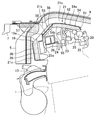
- the engine 1 and the heat insulating covers 8 and 9 there are provided three rectifying members 17 to 19 arranged adjacent to each other in the vehicle front-rear direction for guiding the traveling wind to the exhaust manifold 13.
- the first rectifying member 17 provided on the upper side of the upper front portion of the engine 1 the second rectifying member 18 provided on the rear side of the first rectifying member 17 (upper side of the upper rear portion of the engine 1), and the engine 3 is a third rectifying member 19 provided on the rear side of the upper portion of 1.
- the rectifying members 17 to 19 are arranged in the vehicle front-rear direction, and together, the traveling wind for guiding the traveling wind to the exhaust manifold 13 between the heat insulating covers 8 and 9.
- a passage 21 (see FIG. 1) is formed.
- FIG. 5 is a view of the engine 1 as viewed from above with the first rectifying member 17 removed. Below the first rectifying member 17, fuel system parts of the engine 1 are arranged.
- reference numeral 22 denotes a fuel supply common rail (fuel rail) extending in the cylinder row direction of the engine 1, and each fuel supply pipe 23 branched from the common rail 22 is connected to a fuel injection valve of each cylinder.
- an oil separator 24 having a cavity inside is provided below the second rectifying member 18.
- the oil separator 24 is formed by attaching a baffle plate 26 to the lower surface of the protruding portion 25 a protruding upward from the cylinder head cover 25.
- the first rectifying member 17 is formed by attaching a foamed resin insulator 32 to the lower surface of the synthetic resin plate 31.
- the second rectifying member 18 is formed by attaching an insulator 34 made of foamed resin on the upper surface of a light metal (for example, aluminum alloy) plate 33.
- the third rectifying member 19 is formed by covering the rear surface of the foamed resin insulator 35 with a light metal (for example, aluminum alloy) plate 36.
- the upper surface of the first rectifying member 17 is substantially horizontal and smooth so as to rectify the traveling wind so as to flow backward along the upper surface. Further, an opening 20 is formed between the front end of the first rectifying member 17 and the engine 1 so that the traveling wind flows between the first rectifying member 17 and the engine 1.
- the second rectifying member 18 has a smooth inclination in which the upper surface is inclined downward toward the rear so that the traveling air rectified by the first rectifying member 17 is directed to the exhaust manifold 13 as an exhaust system component along the upper surface. It is a surface. That is, the upper surface of the plate 33 of the second rectifying member 18 is an inclined surface 33a inclined downward toward the rear of the vehicle, and the upper surface of the insulator 34 attached to the plate 33 also follows the inclination of the plate 33.
- the inclined surface 34a is inclined downward.
- the inclined surfaces 33a, 34a of the second rectifying member 18 and the cowl front panel 7 face each other in the vehicle front-rear direction.
- the third rectifying member 19 is a smooth inclined surface 19a whose upper surface is inclined downward toward the rear so that the traveling air rectified by the second rectifying member 18 is directed to the exhaust manifold 13 along the upper surface. Yes.
- the height of the rear end of the upper surface of the first rectifying member 17 is substantially the same as the front end of the insulator 34 of the second rectifying member 18.
- the inclined surface 34a of the second rectifying member 18 and the inclined surface 19a of the third rectifying member 19 are substantially flush with each other.
- the traveling wind passage 21 between the heat insulating covers 8 and 9 and the rectifying members 17 to 19 descends toward the rear of the vehicle following the first passage 21a and the first passage 21a extending substantially horizontally in the vehicle longitudinal direction.
- An inclined second passage 21b and a third passage 21c extending downward toward the exhaust manifold 13 are provided following the second passage 21a.
- the first passage 21 a is formed between the upper heat insulating cover 9 and the first rectifying member 17, and the second passage 21 b is formed between the rear portion of the upper heat insulating cover 9 and the upper portion of the rear heat insulating cover 8 and the second rectifying member 18.
- the third passage 21 c is formed between the inclined surface and the inclined surface of the third rectifying member 19, and the third passage 21 c is formed between the lower portion of the rear heat retaining cover 8 and the rear surface of the third rectifying member 19.
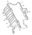
- FIG. 7 to 9 show a state in which the plates 33 of the first rectifying member 17 and the second rectifying member 18 are combined.
- a bowl-shaped attachment portion 37 protruding forward is provided at the front end of the first rectifying member 17.
- the mounting portion 37 is fixed to the engine 1 as shown in FIG.
- leg portions 41 are provided at intervals in the vehicle width direction at the front end portion of the inclined plate 33 of the second rectifying member 18.
- the leg 41 is fixed to the cylinder head of the engine 1 as shown in FIG.
- four mounting portions 42 protruding rearward are provided at intervals in the vehicle width direction.
- the mounting portion 42 is fixed to the cylinder head of the engine 1 as shown in FIGS.
- the upper surface of the plate 33 is formed smoothly, and a concave groove extending in the vehicle front-rear direction is formed on the lower surface in order to increase bending rigidity (bending rigidity around an axis extending in the vehicle width direction).
- the plate 36 is fixed to the cylinder head of the engine 1 at the attachment portion 36 a, and the insulator 35 is attached to the plate 36.
- the traveling wind flows backward along the smooth upper surface of the first rectifying member 17 through the first passage 21a of the traveling wind passage 21, the traveling wind is efficiently guided to the rear without being disturbed by fuel system components. be able to.
- the traveling wind rectified by the first rectifying member 17 flows along the inclined surface 34 a of the second rectifying member 18 and the inclined surface 19 a of the third rectifying member 19 through the second passage 21 b of the traveling air passage 21.
- the air is rectified so as to be directed to the exhaust manifold 13.
- the traveling wind rectified by the inclined surfaces 34 a and 19 a of the second rectifying member 18 and the third rectifying member 19 flows downward through the third passage 21 c of the traveling air passage 21 toward the exhaust manifold 13.
- the exhaust manifold 13 can be efficiently cooled by the traveling air, so that it is not necessary to provide a wide space for guiding the traveling air to the exhaust system parts on the upper side of the engine 1. Therefore, unnecessary cooling of the engine 1 can be avoided.
- the insulators 32, 34, and 35 of the first to third rectifying members 17 to 19 serve to suppress engine noise from entering the passenger compartment.
- the plate 36 of the third rectifying member 19 protects the insulator 35 from the heat of the exhaust manifold 13.
- the second rectifying member 18 collides with the cowl front panel 7 via the rear heat insulating cover 8 prior to the first rectifying member 17. . That is, the impact load is received by the second rectifying member 18. Therefore, it is possible to avoid a large impact load from being directly applied to the first rectifying member 17 and the fuel system parts (the common rail 22 and the fuel pipe 23) provided on the lower side of the first rectifying member 17. Therefore, it is advantageous in preventing the first rectifying member 17 from being deformed to destroy the fuel system part or the fuel system part from being destroyed by the impact load.
- the portion where the cowl front panel 7 abuts against the second rectifying member 18 is the inclined surface 33a of the plate 33. Therefore, the cowl front panel 7 slides on the inclined surface 33a and deforms upward. Go. That is, the force applied from the cowl front panel 7 to the second rectifying member 18 is released upward along the inclined surface 33a. Therefore, the impact received by the second rectifying member 18 is reduced. Therefore, it is advantageous for protecting the first rectifying member 17 and the fuel system parts 22 and 23 by the second rectifying member 18.
- the oil separator 24 below the plate 33 is deformed along with the deformation. . Therefore, the impact is absorbed by the deformation of the oil separator 24, which is further advantageous for protecting the first rectifying member 17 and the fuel system parts 22 and 23.
- the plate 31 of the first rectifying member 17 is not limited to being made of synthetic resin, but may be made of a light alloy or a metal such as a steel plate.
- the plate 33 of the second rectifying member 18 and the plate 36 of the third rectifying member 19 are not limited to light alloys, but can be made of synthetic resin or steel plate.
- FIG. 11 shows a main part of a structure according to another embodiment.
- This embodiment includes a single rectifying member 51 that functions as both the rectifying members 17 and 18, unlike the previous embodiment including the first rectifying member 17 and the second rectifying member 18 that are separate and independent. There is a feature in the point. Other configurations of the present embodiment are the same as those of the previous embodiment.
- the rectifying member 51 includes a first rectifying unit 52 that rectifies the traveling wind so as to flow rearward along the upper surface, and a second rectifying unit 53 provided on the rear side of the first rectifying unit 52. Yes.
- the second rectification unit 53 rectifies the traveling wind rectified by the first rectification unit 52 so as to be directed toward the exhaust system component (exhaust manifold) along the upper surface, and is inclined downward toward the rear of the vehicle. ing.
- the fuel system parts 22 and 23 of the engine 1 are disposed below the first rectification unit 52.
- An oil separator 24 is disposed below the second rectifying unit 53.
- the first rectifying unit 52 is formed by attaching an insulator 55 made of foamed resin to the lower surface of the front part 54a of a light metal (for example, aluminum alloy) plate 54.
- the second rectifying unit 53 is formed by attaching an insulator 56 made of foamed resin to the upper surface of the rear portion 54b of the plate 54.
- the front portion 54a of the plate 54 extends substantially horizontally in the vehicle front-rear direction, and the upper and lower surfaces thereof are formed smoothly.
- the rear portion 54b of the plate 54 is inclined downward from the rear end of the front portion 54a via a bent portion, and a plurality of structural beads 57 extending in the inclined direction are provided at intervals in the vehicle width direction. That is, the rear portion 54b of the plate 54 has a corrugated shape having a plurality of structural beads 57, and therefore has higher bending rigidity (bending rigidity around the axis extending in the vehicle width direction) than the front portion 54a of the plate 54. It has become. Further, the inclined upper surface of the insulator 56 of the second rectifying unit 53 is smooth.
- the rigidity of the second rectifying unit 53 is high, when the cowl front panel 7 hits the inclined surface of the second rectifying unit 53, the cowl front panel 7 slides on the inclined surface and deforms upward. It becomes easy. That is, the force applied from the cowl front panel 7 to the second rectifying unit 53 is easily released upward along the inclined surface.
- the second rectification unit 53 may have a higher rigidity by making the plate thickness thicker than that of the first rectification unit 52.
- the rectifying member 51 is not limited to a light alloy but can be made of a steel plate or a synthetic resin.
Landscapes
- Engineering & Computer Science (AREA)
- Chemical & Material Sciences (AREA)
- Combustion & Propulsion (AREA)
- Mechanical Engineering (AREA)
- Transportation (AREA)
- General Engineering & Computer Science (AREA)
- Physics & Mathematics (AREA)
- Acoustics & Sound (AREA)
- Body Structure For Vehicles (AREA)
- Cooling, Air Intake And Gas Exhaust, And Fuel Tank Arrangements In Propulsion Units (AREA)
- Exhaust Silencers (AREA)
Abstract
エンジン1は、車両前後方向における後側に排気系部品が設けられた後方排気エンジンである。このエンジン1は、エンジン上側に設けられ走行風を後方へ流れるように整流する第1整流部材17と、第1整流部材17の後側に隣接し第1整流部材17によって整流された走行風を、排気系部品13を指向するように整流する第2整流部材18とを備え、第1整流部材17の下側に燃料系部品22,23が配設されている。
Description
本発明はエンジンの上部構造に関する。
特許文献1は、エンジンルームの上面遮蔽用の上面カバーと、側面遮蔽用の左右両側面カバーが一体になった構造を有し、エンジンと変速機よりなるパワートレインの上側を囲むカプセル化部材を開示する。そのカプセル化部材の内面にはインシュレータが設けられている。また、同文献1は、走行風を排気系部品に導くガイドを側面カバーの内側面に設けることを開示する。
エンジン上面には、点火コイルや、燃料供給用のコモンレール、コモンレールと燃料噴射弁とを接続する燃料パイプ等の燃料系部品が配設されている。そのため、カプセル化部材の上面カバーとエンジンの間に走行風を導入してエンジン背部の排気系部品を冷却しようとしても、その走行風が燃料系部品等に当たることによって走行風の流れが乱れる。従って、排気系部品を効率良く冷却することができない。
カプセル化部材とエンジンとの隙間を大きくして走行風の導入量を増大させることも考えられるが、そうすると、カプセル化部材によるエンジンの保温性能が低下する。
そこで、本発明者は、燃料系部品を走行風の整流部材で覆うことを検討した。つまり、走行風が当該整流部材の上面に沿って流れるようにするという対策である。これによれば、走行風を燃料系部品等によって乱されることなく排気系部品に導くことが可能になる。
しかし、車両の前突(前面衝突)時にエンジンが障害物に押されて後退したとき、整流部材がエンジンと共に後退してカウル部材等の車体構成部材に衝突し、整流部材が破壊されることに伴って燃料系部品が破壊される懸念がある。
すなわち、本発明は、走行風による排気系部品の冷却と前突時の燃料系部品の保護の両立を図ることを課題とする。
本発明は、上記課題を解決するために、走行風を排気系部品に導く整流部材に工夫を加えて車両前突時に燃料系部品が車体構成部材との衝突から防護されるようにした。
ここに開示するエンジンの上部構造は、車両前後方向における後側に排気系部品が設けられた後方排気エンジンを前提し、
上記エンジンの上側に設けられた部材であって、走行風を上面に沿わせて後方へ流れるように整流する第1整流部材と、
上記第1整流部材の後側に設けられた部材であって、上記第1整流部材によって整流された走行風を上面に沿わせて上記排気系部品を指向するように整流する第2整流部材とを備え、
上記第1整流部材の下側に上記エンジンの燃料系部品が配設されていることを特徴とする。
上記エンジンの上側に設けられた部材であって、走行風を上面に沿わせて後方へ流れるように整流する第1整流部材と、
上記第1整流部材の後側に設けられた部材であって、上記第1整流部材によって整流された走行風を上面に沿わせて上記排気系部品を指向するように整流する第2整流部材とを備え、
上記第1整流部材の下側に上記エンジンの燃料系部品が配設されていることを特徴とする。
これによれば、走行風が第1整流部材の上面に沿って後方へ流れるから、走行風を燃料系部品によって乱されることなく効率良く後方へ導くことができる。そして、第1整流部材によって整流された走行風が第2整流部材によって排気系部品を指向するように整流されるから、その排気系部品を効率良く冷却することができる。そのため、エンジンの上側に走行風を排気系部品に導くための広いスペースを設ける必要がなくなり、従って、エンジンを不必要に冷却することも避けられる。
車両の前突に伴ってエンジンが後退したときは、第1整流部材に先んじて、車両前後方向の後側にある第2整流部材がカウル部材等の車体構成部材に衝突する。これにより、衝撃荷重が第2整流部材によって受けられる。換言すれば、第2整流部材によって衝撃が吸収される。そのため、第1整流部材が第2整流部材と一緒になって破壊されることが避けられ、或いは第1整流部材の下側に設けられている燃料系部品に大きな衝撃荷重が直接加わることが避けられる。よって、第1整流部材が変形して燃料系部品が破壊されること、或いは燃料系部品が上記衝撃荷重によって破壊されることを防止する上で有利になる。
好ましい実施形態では、上記第2整流部材の後方にダッシュパネルの上部から前方に延びるカウル部材が設けられていて、
上記第2整流部材は、走行風を上記排気系部品に指向させる後方に向かって下降傾斜した傾斜面を有し、
上記カウル部材と上記第2整流部材の傾斜面が車両前後方向に相対している。
上記第2整流部材は、走行風を上記排気系部品に指向させる後方に向かって下降傾斜した傾斜面を有し、
上記カウル部材と上記第2整流部材の傾斜面が車両前後方向に相対している。
これによれば、車両の前突に伴ってエンジンが後退し、カウル部材が第2整流部材の傾斜面に突き当たったとき、カウル部材が当該傾斜面を滑って上方向に変形していくことになる。すなわち、カウル部材から第2整流部材に加わる力が傾斜面に沿って上側に逃される形になる。そのため、第2整流部材が受ける衝撃が小さくなる。よって、第2整流部材による第1整流部材及び燃料系部品の防護に有利になる。
好ましい実施形態では、上記第2整流部材の下側に、内部に空洞を有するオイルセパレータが設けられている。
これにより、第2整流部材が車体構成部材との衝突によって変形していくとき、オイルセパレータが変形することによって、衝撃が一部吸収されるから、第1整流部材及び燃料系部品の防護に有利になる。
好ましい実施形態では、上記第2整流部材とボンネットの間に、上記第2整流部材を走行風が通る隙間を存して覆うカバー部材が設けられている。
従って、カバー部材によってエンジンの保温効果を高めることができるとともに、カバー部材を、走行風を排気系部品に導くための走行風の整流に利用することができる。そのため、排気系部品を効率良く冷却することができる。
好ましい実施形態では、走行風が上記エンジンと上記第1整流部材との間に流入するように、上記エンジンと上記第1整流部材の前端の間に開口が設けられている。
これにより、第1整流部材の下側に設けられている燃料系部品を走行風によって冷却することができ、その異常昇温の防止に有利になる。
また、ここに開示するエンジンの上部構造は、車両前後方向における後側に排気系部品が設けられた後方排気エンジンを前提とし、
上記エンジンの上側に設けられた部材であって、走行風を上面に沿わせて上記排気系部品を指向するように整流する整流部材を備え、
上記整流部材は、第1整流部と、該第1整流部よりも後側に設けられた第2整流部とを備え、
上記第1整流部の下側に上記エンジンの燃料系部品が配設されていて、
上記第2整流部は上記第1整流部よりも剛性が高いことを特徴とする。
上記エンジンの上側に設けられた部材であって、走行風を上面に沿わせて上記排気系部品を指向するように整流する整流部材を備え、
上記整流部材は、第1整流部と、該第1整流部よりも後側に設けられた第2整流部とを備え、
上記第1整流部の下側に上記エンジンの燃料系部品が配設されていて、
上記第2整流部は上記第1整流部よりも剛性が高いことを特徴とする。
これによれば、走行風が整流部材の上面に沿って後方へ流れるから、走行風を燃料系部品によって乱されることなく効率良く後方へ導くことができる。そして、走行風が排気系部品を指向するように整流されるから、その排気系部品を効率良く冷却することができる。そのため、エンジンの上側に走行風を排気系部品に導くための広いスペースを設ける必要がないから、エンジンを不必要に冷却することも避けられる。
車両の前突に伴ってエンジンが後退し、整流部材がカウル部材等の車体構成部材に衝突したときは、衝撃荷重が剛性の高い第2整流部によって受けられる。そのため、第1整流部や該第1整流部の下側に設けられている燃料系部品に大きな衝撃荷重が直接加わることが避けられる。よって、第1整流部が変形して燃料系部品が破壊されること、或いは燃料系部品が上記衝撃荷重によって破壊されることを防止する上で有利になる。また、整流部材を第2整流部に限って高剛性にするから、車両の重量増大も抑制される。
好ましい実施形態では、上記第2整流部の後方にダッシュパネルの上部から前方に延びるカウル部材が設けられていて、
上記第2整流部は、走行風を上記排気系部品に指向させる後方に向かって下降傾斜した傾斜面を有し、
上記カウル部材と上記第2整流部の傾斜面が車両前後方向に相対している。
上記第2整流部は、走行風を上記排気系部品に指向させる後方に向かって下降傾斜した傾斜面を有し、
上記カウル部材と上記第2整流部の傾斜面が車両前後方向に相対している。
これによれば、車両の前突に伴ってエンジンが後退し、カウル部材が第2整流部の傾斜面に突き当たったとき、そのカウル部材が当該傾斜面を滑って上方向に変形していくことになる。すなわち、カウル部材から第2整流部に加わる力が傾斜面に沿って上側に逃される形になる。そのため、第2整流部が受ける衝撃が小さくなる。よって、第2整流部による第1整流部及び燃料系部品の防護に有利になる。
好ましい実施形態では、上記第2整流部の下側に、内部に空洞を有するオイルセパレータが設けられている。
これにより、第2整流部が車体構成部材との衝突によって変形していくとき、オイルセパレータが変形することによって、衝撃が一部吸収されるから、第1整流部及び燃料系部品の防護に有利になる。
好ましい実施形態では、上記第2整流部とボンネットの間に、上記第2整流部を走行風が通る隙間を存して覆うカバー部材が設けられている。
従って、カバー部材によってエンジンの保温効果を高めることができるとともに、カバー部材を、走行風を排気系部品に導くための走行風の整流に利用することができる。そのため、排気系部品を効率良く冷却することができる。
好ましい実施形態では、走行風が上記エンジンと上記整流部材との間に流入するように、上記エンジンと上記整流部材の前端の間に開口が設けられている。
これにより、第1整流部の下側に設けられている燃料系部品を走行風によって冷却することができ、その異常昇温の防止に有利になる。
本発明によれば、走行風を燃料系部品によって乱されることなく効率良く後方へ導いて排気系部品を指向させることができるから、エンジンを不必要に冷却することなく、排気系部品を効率良く冷却することができるとともに、車両の前突に伴ってエンジンが後退したときは、カウル部材等の車体構成部材との衝突に伴う衝撃荷重が第2整流部材又は第2整流部によって受けられるから、燃料系部品の防護に有利になる。
以下、本発明を実施するための形態を図面に基づいて説明する。以下の好ましい実施形態の説明は、本質的に例示に過ぎず、本発明、その適用物或いはその用途を制限することを意図するものではない。
図1に示す車両のエンジンの上部構造において、1はエンジン、2はエンジンルーム3とその後方の車室4を仕切るダッシュパネル、5はダッシュパネル2の上部に設けられたカウルパネル、6はエンジンルーム3を覆うボンネットである。図2にも示すように、カウルパネル5の下端部にダッシュパネル2の上部より前方に延びるカウルフロントパネル7が接合されている。図3にも示すように、このカウルフロントパネル7の前端部にエンジン1の上部を後側から覆う背部保温カバー8が固定されている。また、背部保温カバー8の上端部にエンジン1を上から覆う上部保温カバー9の後端部が支持されて固定されている。
保温カバー8,9は、合成樹脂製プレートの内面に発泡樹脂製インシュレータが貼り付けられてなる。図2において、11はラジエータである。
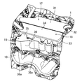
図1に示すように、エンジン1は、車両前後方向の前側に吸気系部品としての吸気マニホールド12が配設され、後側に排気系部品としての排気マニホールド13が配設された後方排気エンジンである。図1において、14はターボ過給機、15はインタークーラである。エンジン1と保温カバー8,9の間には、走行風を排気マニホールド13に導くための互いに車両前後方向に隣接して並ぶ3つの整流部材17~19が設けられている。すなわち、エンジン1の上面前部の上側に設けられた第1整流部材17、該第1整流部材17の後側(エンジン1の上面後部の上側)に設けられた第2整流部材18、並びにエンジン1の上部の後側に設けられた第3整流部材19である。
図4にも示すように、整流部材17~19は、車両前後方向に並んでおり、この三者相俟って、保温カバー8,9との間に走行風を排気マニホールド13に導く走行風通路21(図1参照)を形成している。
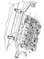
図5は第1整流部材17を外してエンジン1を上から見た図である。第1整流部材17の下側には、エンジン1の燃料系部品が配設されている。同図において、22はエンジン1の気筒列方向に延びる燃料供給用のコモンレール(フューエルレール)であり、コモンレール22から分岐した各燃料供給管23が各気筒の燃料噴射弁に接続されている。
図6に図1の一部を拡大して示すように、第2整流部材18の下側には、内部に空洞を有するオイルセパレータ24が設けられている。オイルセパレータ24は、シリンダヘッドカバー25の上方に突き出した突出部25aの下面にバッフルプレート26を取り付けることによって形成されている。
第1整流部材17は、合成樹脂製プレート31の下面に発泡樹脂製のインシュレータ32を貼り付けてなる。第2整流部材18は、軽金属(例えばアルミニウム合金)製プレート33の上面に発泡樹脂製のインシュレータ34を貼り付けてなる。第3整流部材19は、発泡樹脂製のインシュレータ35の後面を軽金属(例えばアルミニウム合金)製プレート36で覆ってなる。
第1整流部材17は、走行風を上面に沿わせて後方へ流れるように整流するべく、その上面が略水平になっており、且つ平滑になっている。また、走行風が第1整流部材17とエンジン1との間に流入するように、第1整流部材17の前端とエンジン1との間に開口20が形成されている。
第2整流部材18は、第1整流部材17によって整流された走行風を上面に沿わせて排気系部品としての排気マニホールド13を指向させるべく、その上面が後方に向かって下降傾斜した平滑な傾斜面になっている。すなわち、第2整流部材18のプレート33の上面は車両後方に向かって下降傾斜した傾斜面33aになっており、このプレート33に貼り付けられたインシュレータ34の上面もプレート33の当該傾斜に倣って下降傾斜した傾斜面34aになっている。第2整流部材18の傾斜面33a,34aとカウルフロントパネル7は車両前後方向に相対している。
第3整流部材19は、第2整流部材18によって整流された走行風を上面に沿わせて排気マニホールド13を指向させるべく、その上面が後方に向かって下降傾斜した平滑な傾斜面19aになっている。
第1整流部材17の上面後端の高さは第2整流部材18のインシュレータ34の前端と略同じ高さになっている。第2整流部材18の傾斜面34aと第3整流部材19の傾斜面19aは略面一になっている。
上記構成により、保温カバー8,9と整流部材17~19の間の走行風通路21は、車両前後方向に略水平に延びる第1通路21a、第1通路21aに続いて車両後方に向かって下降傾斜した第2通路21b、並びに第2通路21aに続いて排気マニホールド13に向かって下方へ延びる第3通路21cを備えている。
すなわち、第1通路21aは、上部保温カバー9と第1整流部材17の間に形成され、第2通路21bは、上部保温カバー9の後部及び後部保温カバー8の上部と第2整流部材18の傾斜面及び第3整流部材19の傾斜面との間に形成され、第3通路21cは、後部保温カバー8の下部と第3整流部材19の後面との間に形成されている。
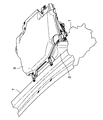
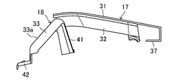
図7~図9に第1整流部材17と第2整流部材18のプレート33を組み合わせた状態で示す。第1整流部材17の前端には前方に突出した鉤型の取付部37が設けられている。この取付部37が図10に示すようにエンジン1に固定されている。
第2整流部材18の傾斜したプレート33の前端部には4本の脚部41が車幅方向に間隔をおいて設けられている。この脚部41が図5に示すようにエンジン1のシリンダヘッドに固定されている。プレート33の後端部には後方へ突出した4つの取付部42が車幅方向に間隔をおいて設けられている。この取付部42が図4及び図5に示すようにエンジン1のシリンダヘッドに固定されている。プレート33の上面は平滑に形成され、下面には曲げ剛性(車幅方向に延びる軸回りの曲げ剛性)を高めるべく、車両前後方向に延びる凹溝が形成されている。
第3整流部材19については、図4に示すように、プレート36が取付部36aにおいてエンジン1のシリンダヘッドに固定され、このプレート36にインシュレータ35が取り付けられている。
<整流部材17~19の作用効果>
車両の走行中、車両のフロントグリル(図示省略)からエンジンルーム3に入る走行風の一部は、保温カバー8,9と整流部材17~19の間に形成された走行風通路21に流入し、排気マニホールド13に向かって後方へ流れる。
車両の走行中、車両のフロントグリル(図示省略)からエンジンルーム3に入る走行風の一部は、保温カバー8,9と整流部材17~19の間に形成された走行風通路21に流入し、排気マニホールド13に向かって後方へ流れる。
まず、走行風は、走行風通路21の第1通路21aを第1整流部材17の平滑な上面に沿って後方へ流れるから、走行風を燃料系部品によって乱されることなく効率良く後方へ導くことができる。
続いて、第1整流部材17によって整流された走行風は、走行風通路21の第2通路21bを第2整流部材18の傾斜面34a及び第3整流部材19の傾斜面19aに沿って流れることで、排気マニホールド13を指向するように整流される。
続いて、第2整流部材18及び第3整流部材19の傾斜面34a,19aによって整流された走行風は、走行風通路21の第3通路21cを排気マニホールド13に向かって下方に流れる。
以上により、排気マニホールド13が走行風によって効率良く冷却され、排気マニホールド13に近接して排気ガス浄化用触媒を配置しても、温度が過度に高い排気ガスが当該触媒に流入することを避けることができ、当該触媒の熱劣化の防止に有利になる。また、このように、排気マニホールド13を走行風によって効率良く冷却することができるから、エンジン1の上側に走行風を排気系部品に導くための広いスペースを設ける必要がない。よって、エンジン1を不必要に冷却することが避けられる。
また、走行風の一部がエンジン1と第1整流部材17の前端の間の開口20からエンジン1と第1整流部材17の間に冷却風として流入することにより、燃料系部品22,23の異常昇温が避けられる。
また、第1乃至第3の整流部材17~19のインシュレータ32,34,35はエンジン騒音が車室内に入ることを抑制する役割を果たす。
第3整流部材19のプレート36はインシュレータ35を排気マニホールド13の熱から保護する。
次に、車両の前突に伴ってエンジン1が後退したときは、第1整流部材17に先んじて、第2整流部材18が後部保温カバー8を介してカウルフロントパネル7に衝突することになる。すなわち、衝撃荷重が第2整流部材18によって受けられる。そのため、第1整流部材17や該第1整流部材17の下側に設けられている燃料系部品(コモンレール22や燃料配管23)に大きな衝撃荷重が直接加わることが避けられる。よって、第1整流部材17が変形して燃料系部品が破壊されること、或いは燃料系部品が上記衝撃荷重によって破壊されることを防止する上で有利になる。
また、上記前突時において、カウルフロントパネル7が第2整流部材18に突き当たる部分は、プレート33の傾斜面33aであるから、カウルフロントパネル7は傾斜面33aを滑って上方向に変形していく。すなわち、カウルフロントパネル7から第2整流部材18に加わる力が傾斜面33aに沿って上側に逃される。よって、第2整流部材18が受ける衝撃が小さくなる。よって、第2整流部材18による第1整流部材17及び燃料系部品22,23の防護に有利になる。
また、上記前突時に第2整流部材18のプレート33がカウルフロントパネル7との衝突によって変形していくとき、その変形に伴って、プレート33の下側にあるオイルセパレータ24が変形していく。従って、オイルセパレータ24の変形によって衝撃が吸収されることになり、上記第1整流部材17及び燃料系部品22,23の防護にさらに有利になる。
なお、第1整流部材17のプレート31は、合成樹脂製に限らず、軽合金、或いは鋼板等の金属製とすることができる。
第2整流部材18のプレート33及び第3整流部材19のプレート36は、軽合金製に限らず、合成樹脂製或いは鋼板製とすることができる。
<別の実施形態>
図11に別の実施形態に係る構造の要部を示す。この実施形態は、別個独立の第1整流部材17と第2整流部材18を備える先の実施形態とは違って、この両整流部材17,18の機能を兼ねる一つの整流部材51を備えている点に特徴がある。本実施形態の他の構成は先の実施形態と同じである。
図11に別の実施形態に係る構造の要部を示す。この実施形態は、別個独立の第1整流部材17と第2整流部材18を備える先の実施形態とは違って、この両整流部材17,18の機能を兼ねる一つの整流部材51を備えている点に特徴がある。本実施形態の他の構成は先の実施形態と同じである。
整流部材51は、走行風を上面に沿わせて後方へ流れるように整流する第1整流部52と、第1整流部52に続いてその後側に設けられた第2整流部53とを備えている。第2整流部53は、第1整流部52によって整流された走行風を上面に沿わせて排気系部品(排気マニホールド)を指向するように整流するものであり、車両後方に向かって下降傾斜している。
第1整流部52の下側にエンジン1の燃料系部品22,23が配設されている。第2整流部53の下側にオイルセパレータ24が配設されている。
第1整流部52は、軽金属(例えばアルミニウム合金)製プレート54の前部54aの下面に発泡樹脂製のインシュレータ55を貼り付けてなる。第2整流部53は、上記プレート54の後部54bの上面に発泡樹脂製のインシュレータ56を貼り付けてなる。
プレート54の前部54aは、車両前後方向に略水平に延びており、その上面及び下面は平滑に形成されている。プレート54の後部54bは、前部54aの後端から屈曲部を介して下降傾斜しており、当該傾斜方向に延びる複数の構造ビード57が車幅方向に間隔をおいて設けられている。すなわち、プレート54の後部54bは、複数の構造ビード57を有する波板状になっており、そのため、プレート54の前部54aよりも曲げ剛性(車幅方向に延びる軸まわりの曲げ剛性)が高くなっている。また、第2整流部53のインシュレータ56の傾斜した上面は平滑になっている。
本実施形態も、走行風の整流に関しては、先の実施形態と同様の効果が得られる。
車両の前突に伴うエンジン1の後退し、整流部材51がカウルフロントパネル7に衝突したときは、衝撃荷重が第2整流部53の剛性が高いプレート後部54bの傾斜面58によって受けられる。そのため、第1整流部52や燃料系部品22,23に大きな衝撃荷重が直接加わることが避けられる。よって、第1整流部52が変形して燃料系部品22,23が破壊されること、或いは燃料系部品22,23が上記衝撃荷重によって破壊されることを防止することができる。
また、第2整流部53の剛性が高いから、カウルフロントパネル7が第2整流部53の傾斜面に突き当たったとき、そのカウルフロントパネル7が当該傾斜面を滑って上方向に変形していき易くなる。すなわち、カウルフロントパネル7から第2整流部53に加わる力が傾斜面に沿って上側に逃され易くなる。
第2整流部53は第1整流部52よりも板厚を厚くすることによって高剛性にしてもよい。
また、整流部材51は、軽合金製に限らず、鋼板製、或いは合成樹脂製とすることもできる。
1 エンジン
2 ダッシュパネル
3 エンジンルーム
4 車室
5 カウルパネル
6 ボンネット
7 カウルフロントパネル
8,9 保温カバー
13 排気マニホールド(排気系部品)
17 第1整流部材
18 第2整流部材
19 第3整流部材
20 開口
22 燃料供給用コモンレール(燃料系部品)
23 燃料供給管(燃料系部品)
24 オイルセパレータ
33a 傾斜面
34a 傾斜面
51 整流部材
52 第1整流部
53 第2整流部
57 構造ビード
2 ダッシュパネル
3 エンジンルーム
4 車室
5 カウルパネル
6 ボンネット
7 カウルフロントパネル
8,9 保温カバー
13 排気マニホールド(排気系部品)
17 第1整流部材
18 第2整流部材
19 第3整流部材
20 開口
22 燃料供給用コモンレール(燃料系部品)
23 燃料供給管(燃料系部品)
24 オイルセパレータ
33a 傾斜面
34a 傾斜面
51 整流部材
52 第1整流部
53 第2整流部
57 構造ビード
Claims (10)
- エンジンの車両前後方向における後側に排気系部品が設けられた後方排気エンジンの上部構造であって、
上記エンジンの上側に設けられた部材であって、走行風を上面に沿わせて後方へ流れるように整流する第1整流部材と、
上記第1整流部材の後側に設けられた部材であって、上記第1整流部材によって整流された走行風を上面に沿わせて上記排気系部品を指向するように整流する第2整流部材とを備え、
上記第1整流部材の下側に上記エンジンの燃料系部品が配設されていることを特徴とするエンジンの上部構造。 - 請求項1において、
上記第2整流部材の後方にダッシュパネルの上部から前方に延びるカウル部材が設けられていて、
上記第2整流部材は、走行風を上記排気系部品に指向させる後方に向かって下降傾斜した傾斜面を有し、
上記カウル部材と上記第2整流部材の傾斜面が車両前後方向に相対していることを特徴とするエンジンの上部構造。 - 請求項1又は請求項2において、
上記第2整流部材の下側に、内部に空洞を有するオイルセパレータが設けられていることを特徴とするエンジンの上部構造。 - 請求項1乃至請求項3のいずれか一において、
上記第2整流部材とボンネットの間に、上記第2整流部材を走行風が通る隙間を存して覆うカバー部材が設けられていることを特徴とするエンジンの上部構造。 - 請求項1乃至請求項4のいずれか一において、
走行風が上記エンジンと上記第1整流部材との間に流入するように、上記エンジンと上記第1整流部材の前端の間に開口が設けられていることを特徴とするエンジンの上部構造。 - エンジンの車両前後方向における後側に排気系部品が設けられた後方排気エンジンの上部構造であって、
上記エンジンの上側に設けられた部材であって、走行風を上面に沿わせて上記排気系部品を指向するように整流する整流部材を備え、
上記整流部材は、第1整流部と、該第1整流部よりも後側に設けられた第2整流部とを備え、
上記第1整流部の下側に上記エンジンの燃料系部品が配設されていて、
上記第2整流部は上記第1整流部よりも剛性が高いことを特徴とするエンジンの上部構造。 - 請求項6において、
上記第2整流部の後方にダッシュパネルの上部から前方に延びるカウル部材が設けられていて、
上記第2整流部は、走行風を上記排気系部品に指向させる後方に向かって下降傾斜した傾斜面を有し、
上記カウル部材と上記第2整流部の傾斜面が車両前後方向に相対していることを特徴とするエンジンの上部構造。 - 請求項6又は請求項7において、
上記第2整流部の下側に、内部に空洞を有するオイルセパレータが設けられていることを特徴とするエンジンの上部構造。 - 請求項6乃至請求項8のいずれか一において、
上記第2整流部とボンネットの間に、上記第2整流部を走行風が通る隙間を存して覆うカバー部材が設けられていることを特徴とするエンジンの上部構造。 - 請求項6乃至請求項9のいずれか一において、
走行風が上記エンジンと上記整流部材との間に流入するように、上記エンジンと上記整流部材の前端の間に開口が設けられていることを特徴とするエンジンの上部構造。
Priority Applications (3)
| Application Number | Priority Date | Filing Date | Title |
|---|---|---|---|
| US16/490,865 US10913347B2 (en) | 2017-03-24 | 2018-02-15 | Upper structure of engine |
| EP18771650.1A EP3578402B1 (en) | 2017-03-24 | 2018-02-15 | Vehicle with an internal combustion engine |
| CN201880015855.8A CN110662666B (zh) | 2017-03-24 | 2018-02-15 | 发动机的上部构造 |
Applications Claiming Priority (2)
| Application Number | Priority Date | Filing Date | Title |
|---|---|---|---|
| JP2017059474A JP6432631B2 (ja) | 2017-03-24 | 2017-03-24 | エンジンの上部構造 |
| JP2017-059474 | 2017-03-24 |
Publications (1)
| Publication Number | Publication Date |
|---|---|
| WO2018173556A1 true WO2018173556A1 (ja) | 2018-09-27 |
Family
ID=63584311
Family Applications (1)
| Application Number | Title | Priority Date | Filing Date |
|---|---|---|---|
| PCT/JP2018/005147 Ceased WO2018173556A1 (ja) | 2017-03-24 | 2018-02-15 | エンジンの上部構造 |
Country Status (5)
| Country | Link |
|---|---|
| US (1) | US10913347B2 (ja) |
| EP (1) | EP3578402B1 (ja) |
| JP (1) | JP6432631B2 (ja) |
| CN (1) | CN110662666B (ja) |
| WO (1) | WO2018173556A1 (ja) |
Cited By (1)
| Publication number | Priority date | Publication date | Assignee | Title |
|---|---|---|---|---|
| JP2021126973A (ja) * | 2020-02-13 | 2021-09-02 | マツダ株式会社 | 車両の前部構造 |
Families Citing this family (1)
| Publication number | Priority date | Publication date | Assignee | Title |
|---|---|---|---|---|
| CN114017172A (zh) * | 2021-11-15 | 2022-02-08 | 中国第一汽车股份有限公司 | 发动机风冷系统及具有其的车辆 |
Citations (5)
| Publication number | Priority date | Publication date | Assignee | Title |
|---|---|---|---|---|
| JPH0350523U (ja) * | 1989-09-26 | 1991-05-16 | ||
| JP2009167947A (ja) * | 2008-01-17 | 2009-07-30 | Toyota Motor Corp | オイルセパレータ |
| JP2013119384A (ja) * | 2011-12-07 | 2013-06-17 | Hyundai Motor Co Ltd | 車両のエンジンカプセル化構造物 |
| JP2016130074A (ja) * | 2015-01-13 | 2016-07-21 | トヨタ自動車株式会社 | 車両用導風構造 |
| JP2017013638A (ja) * | 2015-07-01 | 2017-01-19 | スターライト工業株式会社 | エンジンコンパートメントの冷却制御構造 |
Family Cites Families (14)
| Publication number | Priority date | Publication date | Assignee | Title |
|---|---|---|---|---|
| JPH035023U (ja) | 1989-06-05 | 1991-01-18 | ||
| JP3287584B2 (ja) * | 1991-03-25 | 2002-06-04 | ヤマハ発動機株式会社 | 船舶推進機における補機の配置構造 |
| EP1614901B1 (en) * | 2003-03-13 | 2018-12-26 | Yanmar Co., Ltd. | Cover structure for engine |
| US7011071B1 (en) * | 2004-10-27 | 2006-03-14 | Decuir Jr Julian A | Internal boost system for engines |
| JP2007055274A (ja) * | 2005-08-22 | 2007-03-08 | Mazda Motor Corp | 車体前部構造 |
| JP2008013149A (ja) * | 2006-07-10 | 2008-01-24 | Honda Motor Co Ltd | 車両の導風板 |
| JP5267089B2 (ja) * | 2008-12-05 | 2013-08-21 | トヨタ自動車株式会社 | 排気系冷却構造 |
| JP5737301B2 (ja) * | 2013-01-11 | 2015-06-17 | トヨタ自動車株式会社 | 車両用導風構造 |
| FR3007080B1 (fr) * | 2013-06-17 | 2019-05-17 | Suzuki Motor Corporation | Structure d'admission de moteur hors-bord |
| JP6380212B2 (ja) * | 2014-12-09 | 2018-08-29 | 株式会社デンソー | 冷却装置、および冷却モジュール |
| US9840144B2 (en) * | 2015-08-19 | 2017-12-12 | Mazda Motor Corporation | Front air-rectifying structure of automotive vehicle |
| DE112016003786T5 (de) * | 2015-08-20 | 2018-05-09 | Denso Corporation | Kühlvorrichtung |
| US10006336B2 (en) * | 2015-10-27 | 2018-06-26 | Suzuki Motor Corporation | Saddle-ridden vehicle |
| JP6292265B2 (ja) * | 2016-09-07 | 2018-03-14 | マツダ株式会社 | 車両用エンジンの上部構造 |
-
2017
- 2017-03-24 JP JP2017059474A patent/JP6432631B2/ja active Active
-
2018
- 2018-02-15 US US16/490,865 patent/US10913347B2/en active Active
- 2018-02-15 EP EP18771650.1A patent/EP3578402B1/en active Active
- 2018-02-15 WO PCT/JP2018/005147 patent/WO2018173556A1/ja not_active Ceased
- 2018-02-15 CN CN201880015855.8A patent/CN110662666B/zh active Active
Patent Citations (5)
| Publication number | Priority date | Publication date | Assignee | Title |
|---|---|---|---|---|
| JPH0350523U (ja) * | 1989-09-26 | 1991-05-16 | ||
| JP2009167947A (ja) * | 2008-01-17 | 2009-07-30 | Toyota Motor Corp | オイルセパレータ |
| JP2013119384A (ja) * | 2011-12-07 | 2013-06-17 | Hyundai Motor Co Ltd | 車両のエンジンカプセル化構造物 |
| JP2016130074A (ja) * | 2015-01-13 | 2016-07-21 | トヨタ自動車株式会社 | 車両用導風構造 |
| JP2017013638A (ja) * | 2015-07-01 | 2017-01-19 | スターライト工業株式会社 | エンジンコンパートメントの冷却制御構造 |
Non-Patent Citations (1)
| Title |
|---|
| See also references of EP3578402A4 * |
Cited By (2)
| Publication number | Priority date | Publication date | Assignee | Title |
|---|---|---|---|---|
| JP2021126973A (ja) * | 2020-02-13 | 2021-09-02 | マツダ株式会社 | 車両の前部構造 |
| JP7359017B2 (ja) | 2020-02-13 | 2023-10-11 | マツダ株式会社 | 車両の前部構造 |
Also Published As
| Publication number | Publication date |
|---|---|
| US10913347B2 (en) | 2021-02-09 |
| CN110662666B (zh) | 2022-12-27 |
| EP3578402B1 (en) | 2024-05-08 |
| JP2018161932A (ja) | 2018-10-18 |
| CN110662666A (zh) | 2020-01-07 |
| EP3578402A1 (en) | 2019-12-11 |
| US20200031217A1 (en) | 2020-01-30 |
| JP6432631B2 (ja) | 2018-12-05 |
| EP3578402A4 (en) | 2020-01-15 |
Similar Documents
| Publication | Publication Date | Title |
|---|---|---|
| EP2917059B1 (en) | Air guide structure for an engine compartment of a vehicle | |
| JP3531816B2 (ja) | 車両フロアの遮熱装置 | |
| JP2004196287A (ja) | 自動車のリヤパネル部分 | |
| CN110091714A (zh) | 车辆下部结构 | |
| JP6432631B2 (ja) | エンジンの上部構造 | |
| CN102821993B (zh) | 车辆的前车厢 | |
| JP5375082B2 (ja) | 車両のインタークーラ用冷却構造 | |
| JP6380291B2 (ja) | 自動車の下部整流構造 | |
| KR20110121226A (ko) | 엔진 냉각용 덕트 구조 | |
| JP2019182077A (ja) | 車両下部構造 | |
| JP2008049935A (ja) | 車体前部構造 | |
| JP2014024463A (ja) | 車両前部構造 | |
| JP2023077450A (ja) | 車両構造 | |
| JP6536668B1 (ja) | エンジン | |
| JP2020023258A (ja) | 車両床下構造 | |
| JP5573342B2 (ja) | 車両の前部車体構造 | |
| JP2008137591A (ja) | 車両の車体前部構造 | |
| JP2005282488A (ja) | 車両用エンジンの吸気装置 | |
| JP4258527B2 (ja) | 車両の排気熱回収装置の取付構造 | |
| JP2009208609A (ja) | 自動車用エンジンアンダーカバー | |
| JP4370895B2 (ja) | 自動車の排気系の遮熱板 | |
| JP2008095527A (ja) | 内燃機関の排気装置 | |
| JP6450018B2 (ja) | 乗用車用フロントモジュール | |
| JP2019002294A (ja) | 燃料系統保護装置およびこれを備える内燃機関 | |
| JP2021024387A (ja) | 車両の放熱構造 |
Legal Events
| Date | Code | Title | Description |
|---|---|---|---|
| 121 | Ep: the epo has been informed by wipo that ep was designated in this application |
Ref document number: 18771650 Country of ref document: EP Kind code of ref document: A1 |
|
| ENP | Entry into the national phase |
Ref document number: 2018771650 Country of ref document: EP Effective date: 20190905 |
|
| NENP | Non-entry into the national phase |
Ref country code: DE |