WO2018173766A1 - 金型の寿命予測方法 - Google Patents
金型の寿命予測方法 Download PDFInfo
- Publication number
- WO2018173766A1 WO2018173766A1 PCT/JP2018/008922 JP2018008922W WO2018173766A1 WO 2018173766 A1 WO2018173766 A1 WO 2018173766A1 JP 2018008922 W JP2018008922 W JP 2018008922W WO 2018173766 A1 WO2018173766 A1 WO 2018173766A1
- Authority
- WO
- WIPO (PCT)
- Prior art keywords
- mold
- temperature
- thermal stress
- max
- thermal
- Prior art date
- Legal status (The legal status is an assumption and is not a legal conclusion. Google has not performed a legal analysis and makes no representation as to the accuracy of the status listed.)
- Ceased
Links
Images



Classifications
-
- B—PERFORMING OPERATIONS; TRANSPORTING
- B22—CASTING; POWDER METALLURGY
- B22C—FOUNDRY MOULDING
- B22C9/00—Moulds or cores; Moulding processes
- B22C9/06—Permanent moulds for shaped castings
-
- G—PHYSICS
- G06—COMPUTING OR CALCULATING; COUNTING
- G06F—ELECTRIC DIGITAL DATA PROCESSING
- G06F30/00—Computer-aided design [CAD]
- G06F30/20—Design optimisation, verification or simulation
- G06F30/23—Design optimisation, verification or simulation using finite element methods [FEM] or finite difference methods [FDM]
-
- B—PERFORMING OPERATIONS; TRANSPORTING
- B22—CASTING; POWDER METALLURGY
- B22D—CASTING OF METALS; CASTING OF OTHER SUBSTANCES BY THE SAME PROCESSES OR DEVICES
- B22D17/00—Pressure die casting or injection die casting, i.e. casting in which the metal is forced into a mould under high pressure
- B22D17/20—Accessories: Details
- B22D17/22—Dies; Die plates; Die supports; Cooling equipment for dies; Accessories for loosening and ejecting castings from dies
-
- G—PHYSICS
- G01—MEASURING; TESTING
- G01N—INVESTIGATING OR ANALYSING MATERIALS BY DETERMINING THEIR CHEMICAL OR PHYSICAL PROPERTIES
- G01N3/00—Investigating strength properties of solid materials by application of mechanical stress
- G01N3/32—Investigating strength properties of solid materials by application of mechanical stress by applying repeated or pulsating forces
-
- G—PHYSICS
- G01—MEASURING; TESTING
- G01N—INVESTIGATING OR ANALYSING MATERIALS BY DETERMINING THEIR CHEMICAL OR PHYSICAL PROPERTIES
- G01N3/00—Investigating strength properties of solid materials by application of mechanical stress
- G01N3/60—Investigating resistance of materials, e.g. refractory materials, to rapid heat changes
-
- G—PHYSICS
- G06—COMPUTING OR CALCULATING; COUNTING
- G06F—ELECTRIC DIGITAL DATA PROCESSING
- G06F2111/00—Details relating to CAD techniques
- G06F2111/08—Probabilistic or stochastic CAD
-
- G—PHYSICS
- G06—COMPUTING OR CALCULATING; COUNTING
- G06F—ELECTRIC DIGITAL DATA PROCESSING
- G06F2111/00—Details relating to CAD techniques
- G06F2111/10—Numerical modelling
-
- G—PHYSICS
- G06—COMPUTING OR CALCULATING; COUNTING
- G06F—ELECTRIC DIGITAL DATA PROCESSING
- G06F2113/00—Details relating to the application field
- G06F2113/22—Moulding
-
- G—PHYSICS
- G06—COMPUTING OR CALCULATING; COUNTING
- G06F—ELECTRIC DIGITAL DATA PROCESSING
- G06F2119/00—Details relating to the type or aim of the analysis or the optimisation
- G06F2119/04—Ageing analysis or optimisation against ageing
-
- G—PHYSICS
- G06—COMPUTING OR CALCULATING; COUNTING
- G06F—ELECTRIC DIGITAL DATA PROCESSING
- G06F2119/00—Details relating to the type or aim of the analysis or the optimisation
- G06F2119/18—Manufacturability analysis or optimisation for manufacturability
Definitions
- the present invention relates to a method for predicting the thermal fatigue life of a mold.
- An object of the present invention is to provide a method for accurately predicting the thermal fatigue life of a mold.
- the present invention is a method for predicting the thermal fatigue life of a mold made of a mold material having hardness H, in which heating when contacting the workpiece and cooling after contacting the workpiece are repeated, Obtain the temperature distribution of the mold heated by contacting the workpiece, From the above temperature distribution, obtain the thermal stress distribution generated in the mold, Than the thermal stress distribution of the, determined at the position x of the die, and the thermal stress maximum sigma H_max, the temperature T h in the case of the thermal stress maximum sigma H_max, Using a mold material hardness H, determined as yield strength ⁇ y (T h) at a temperature T h, stop at a temperature T c of the mold when cooled ⁇ a (T c), This is a mold life prediction method for obtaining the thermal fatigue life N at the position x of the mold by substituting these ⁇ h_MAX , ⁇ y (T h ) and ⁇ (T c ) into the following relational expression.
- N ⁇ C 1 ( ⁇ y (T h ) / ⁇ h — MAX ) m ⁇ ln (1- ⁇ (T c )) ⁇ 1 ⁇ C 2 ⁇ n (C 1, C 2, m , n are constants)
- the position x of the mold is a work surface having a corner radius of 2.0 mm or less.
- FIG. 1 shows all the steps of a mold life prediction method according to an embodiment of the present invention. Hereinafter, each step will be described in detail.
- step A Determination of mold temperature distribution (step A)> First, it is necessary to know the hardness H of the mold in order to obtain the proof stress and the drawing of the mold material constituting the mold described later. And it consists of the metal mold
- the hardness H can be a value at room temperature.
- the above-mentioned temperature distribution is such that the die-cast part after casting is taken out of the cavity from the state where the die is heated by injecting molten metal into the cavity of the die-casting die. It is a series of temperature distributions of the mold until the mold is cooled. This temperature distribution can be obtained, for example, by numerical calculation such as a finite difference method or a finite element method. At this time, physical property values of the mold material such as specific heat and thermal conductivity are used as a precondition for calculating the temperature distribution, if necessary.
- FIG. 2 shows an example of the temperature distribution of the cross section of the stress concentration portion (concave portion) when the mold 1 is divided into meshes by the dividing element 2.
- the temperature distribution is indicated by a temperature isoline 3.
- the entire mold is divided into meshes and heat load conditions are set.
- a heat load a heat transfer coefficient and an atmospheric temperature can be set, or a heat flux can be set.
- the stress concentration portion is shown two-dimensionally for simplification, but can be analyzed three-dimensionally.
- the temperature actually measured with the actual mold can be used.
- a device that measures the temperature in a non-contact manner such as an infrared thermography can be used.
- a constraint condition is set for this.
- a constraint condition for example, a constraint direction or the like can be set for each side of the dividing element 2 in accordance with a fixed state from the periphery of the mold.
- segmentation element 2 is performed, and a thermal stress distribution map can be created from a calculation result.
- FIG. 3 shows an example of the obtained thermal stress distribution diagram.
- the thermal stress distribution is indicated by the thermal stress isolines 4.
- the position “x s ” indicates a stress concentration part.
- the above-mentioned thermal stress ⁇ h used for the calculation is actually designated as the “highest value” of the thermal stress generated during the mold heating. Is effective.
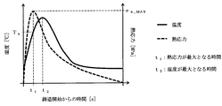
- the time when the temperature is highest at an arbitrary position x varies depending on the position x. Furthermore, the time when the temperature is highest does not necessarily coincide with the time when the thermal stress is highest at the position x.
- FIG. 4 shows the relationship between the temperature during use and the thermal stress at a specific position on the die-casting die surface (cavity surface).
- the horizontal axis represents time from the start of casting, and the vertical axis represents temperature and thermal stress value.
- the thermal stress value increases with increasing temperature of the mold surface, thermal stress takes a maximum value at time t 1.
- the temperature is, then, becomes the maximum at time t 2. Since the thermal stress is determined solely by the ambient temperature field, the thermal stress does not always take the maximum value at the time when the temperature at a specific position becomes the highest. For this reason, for example, after calculating a series of thermal stresses occurring during casting, it is necessary to search for and extract the maximum value of the thermal stress at each position where the life is to be predicted.
- a relational expression described later is prepared, and a value such as the above-described thermal stress ⁇ h is substituted for this to obtain a thermal fatigue life N. It changes depending on the value of the stress ⁇ h . Therefore, also in this respect, in order to improve the prediction accuracy of the mold life, it is desirable to correctly select the maximum value of the value of the thermal stress ⁇ h generated in the mold in use.
- the difference may be small depending on the usage pattern of the mold. Even in such a case, in order to improve the prediction accuracy of the mold life, it is effective to recognize that there is a small difference. And in order to recognize this small difference, the temperature distribution of the metal mold
- the short elapsed time is preferably 0.5 seconds or less. More preferably, it is 0.4 second or less, More preferably, it is 0.3 second or less. And it is still more preferable in order of 0.2 second or less and 0.1 second or less.
- the values of the proof stress ⁇ y (T h ) and the restriction ⁇ (T c ) can be obtained by separately preparing a mold material having a hardness H.
- the hardness H can be a value at room temperature.
- the values of the proof stress ⁇ y (T h ) and the aperture ⁇ (T c ) may be previously measured at various temperatures and converted into a mechanical property database.
- the temperature Tc at the time of cooling is, for example, in the step of taking out a molded product (die cast part) from the mold, when the upper mold and the lower mold are opened, when the molded product is taken out from the mold,
- the surface temperature at the position x of the mold for which the lifetime is predicted, such as when cooled, can be used. In such a case, the surface temperature of the mold can be actually measured, and this measured value can be used.
- required by calculation in the same way as the above by the finite element method etc. can also be used.
- the relationship between the hardness of the mold and the life can be obtained, and "optimum hardness" for a predetermined mold is proposed. can do.
- the life prediction is performed for “one mold” with a specific mold shape and use conditions is shown, but “a plurality of molds with different mold materials according to a specific mold shape and use conditions”. If the life prediction is performed for the “mold”, the relationship between the mold made of various mold materials and the life can be obtained.
- the life prediction is performed by changing the die shape (for example, the radius of curvature of the corner portion) and the usage conditions (such as the temperature of the workpiece) for one die, the mold shape, usage conditions and lifetime It is also possible to ask for a relationship. By these, it is possible to propose an “optimal mold material” for a predetermined mold shape and use conditions.
- the present invention is optimal for predicting the life of a mold in which the time when the thermal stress is maximized and the time when the temperature is maximized are different at an arbitrary position of the mold in use. .
- Such a time lag can occur, for example, at the corner (corner portion) of the work surface in the stress concentration portion of the mold.
- die is a work surface which has a corner radius (corner R) of 2.0 mm or less, for example. More preferably, it is 1.0 mm or less.
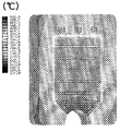
- step A the temperature distribution of the mold in a series of casting cycles was determined according to the above-described procedure (a) (step A).
- FIG. 6 shows a temperature distribution diagram of the work surface when 0.5 seconds have elapsed since the completion of the molten metal injection into the cavity.
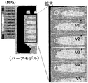
- FIG. 7 shows a thermal stress distribution diagram of the work surface when 0.5 seconds have elapsed from the completion of molten metal injection into the cavity.
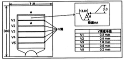
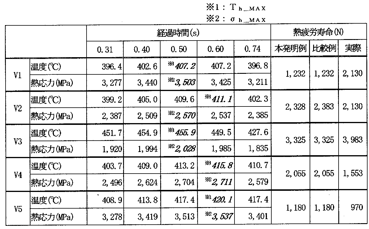
- the thermal fatigue life N at the bottom of each V groove was determined by the method for predicting the thermal fatigue life of the mold. These predicted values of thermal fatigue life N are determined based on the thermal fatigue life N when die casting is actually performed under the conditions shown in Table 1 (that is, thermal fatigue when a crack shown in FIG. 8 occurs at the bottom of the V groove). Life N). The results are shown in Table 3.
- the thermal stress maximum value ⁇ h_MAX and the temperature maximum value T h_MAX are within the range of 0.31 to 0.74 seconds from the completion of molten metal injection into the cavity at the bottom positions of all the V grooves. It was recognized. Then, according to the calculation, the generation time of the above ⁇ h_MAX and Th_MAX was the same in the V groove except for V2 when 0.50 seconds or 0.60 seconds had elapsed from the completion of molten metal injection. , V2 was out of date. As a result, in V2, the predicted thermal fatigue life value was different between the method of predicting the thermal fatigue life of the mold of the present invention and the method of predicting the thermal fatigue life of the mold of the comparative example. The value of the thermal fatigue life obtained by the method for predicting the thermal fatigue life of the mold of the present invention example was close to the actual value of the thermal fatigue life.
Landscapes
- Engineering & Computer Science (AREA)
- Physics & Mathematics (AREA)
- General Physics & Mathematics (AREA)
- Theoretical Computer Science (AREA)
- Biochemistry (AREA)
- Analytical Chemistry (AREA)
- Mechanical Engineering (AREA)
- Pathology (AREA)
- Health & Medical Sciences (AREA)
- Life Sciences & Earth Sciences (AREA)
- Chemical & Material Sciences (AREA)
- Immunology (AREA)
- General Health & Medical Sciences (AREA)
- Computer Hardware Design (AREA)
- General Engineering & Computer Science (AREA)
- Evolutionary Computation (AREA)
- Geometry (AREA)
- Molds, Cores, And Manufacturing Methods Thereof (AREA)
Abstract
Description
しかし、特許文献1の場合、それで予測した金型寿命の、実際の金型寿命に対する精度を高める点で、改善の余地がある。
本発明の目的は、金型の熱疲労寿命を精度良く予測する方法を提供することである。
被加工材に接触することにより加熱された金型の温度分布を求め、
上記の温度分布より、金型に発生する熱応力分布を求め、
上記の熱応力分布より、金型の位置xにおける、熱応力最大値σh_MAXと、この熱応力最大値σh_MAXのときの温度Thとを求め、
硬度Hの金型材を用いて、温度Thにおける耐力σy(Th)と、冷却されたときの金型の温度Tcにおける絞りφ(Tc)とを求め、
これらのσh_MAX、σy(Th)およびφ(Tc)を、以下の関係式に代入することによって、金型の位置xにおける熱疲労寿命Nを求める金型の寿命予測方法である。
N={C1(σy(Th)/σh_MAX)m・ln(1-φ(Tc))-1-C2}n
(C1、C2、m、nは定数)
また、本発明の場合、上記の金型の位置xが、2.0mm以下の隅半径を有する作業面であることが好ましい。
本発明の一実施例による金型寿命の予測方法の全工程を図1に示す。以下、各工程について詳細に説明する。
まず、金型の硬度Hを知っておくことが、後述する金型を構成する金型材の耐力や絞りを求めるために、必要である。そして、この硬度Hの金型材からなり、被加工材に接触したときの加熱と、被加工材に接触した後の冷却とが繰り返される金型の使用中において、被加工材に接触することにより加熱された金型の温度分布を求める。上記の硬度Hは、室温のときの値とすることができる。そして、上記の温度分布は、例えば、ダイカスト金型の場合、そのダイカスト金型のキャビティに溶湯が注入されたことにより金型が加熱された状態から、鋳造後のダイカスト部品がキャビティから取り出され金型が冷却された状態までの金型の一連の温度分布である。この温度分布は、例えば、有限差分法や有限要素法などの数値計算により求めることができる。このとき、温度分布の計算の前提として、必要であれば、比熱、熱伝導率などの金型材の物性値を用いる。
上記の温度分布図(図2)に基づき、金型に発生する熱応力分布を、例えば、有限要素法などの数値計算で求める。このとき、熱応力分布の計算の前提として、必要であれば、応力-歪間の関係における各種係数、線膨張係数などの金型材の物性値を用いる。
そして、各分割要素2の熱応力解析を行い、計算結果から熱応力分布図を作成することができる。図3に、この求めた熱応力分布図の一例を示す。熱応力分布は、熱応力等値線4で示されている。そして、位置「xs」は、応力集中部を示す。
特許文献1の手法は、金型寿命を予測して、目標とする金型寿命の向上に適した金型の硬度や金型材を選定するのに実に有用である。しかし、特許文献1の手法の場合、金型の任意の位置xで、例えば、金型使用中に金型の「温度が最高となる時間」を基準にして、その温度が最高となる時間で“同時に”生じている一対の温度場と応力場との関係から寿命を算出している。このとき、金型寿命の予測精度を向上させるには、その算出に使用する上記の熱応力σhを、実は、金型加熱時に発生する熱応力のうちの「最も高い値」に指定することが効果的である。そして、実際の金型では、任意の位置xで温度が最高となる時間は、その位置x毎で異なる。さらに、上記の温度が最高となる時間は、その位置xにおいて熱応力が最高となる時間と必ずしも一致しない。
そして、本発明の金型の寿命予測方法においては、後述する関係式を用いて熱疲労寿命Nを求めるために、金型の耐力σy(Th)および絞りφ(Tc)を必要とする。このとき、耐力σy(Th)は、温度Thでの値である。また、絞りφ(Tc)は、冷却時の温度Tcでの値である。この耐力σy(Th)および絞りφ(Tc)の値は、硬度Hを有する金型材を別に準備して、求めることができる。この場合、上記の硬度Hは、室温のときの値とすることができる。そして、上記の耐力σy(Th)および絞りφ(Tc)の値は、様々な温度で予め測定しておいたものを、機械的特性データベース化しておいてもよい。
なお、冷却時の温度Tcは、例えば、金型から成形品(ダイカスト部品)を取り出す工程において、上型と下型とを開いたとき、金型から成形品を取り出したとき、金型を冷却したとき等の、寿命予測する金型の位置xにおける表面温度とすることができる。このような場合、金型の表面温度を実際に測定することができ、この実測値を用いることができる。また、有限要素法等により、上記と同じ要領で、計算で求めた結果を使用することもできる。
N={C1(σy(Th)/σh_MAX)m・ln(1-φ(Tc))-1-C2}n
(C1、C2、m、nは定数)
の関係式に代入して、金型の位置xにおける熱疲労寿命Nを求める(工程E)>
そして最後に、上述の工程A~Dによって得た、金型の位置xにおける熱応力最大値σh_MAXと、その時の温度Thでの耐力σy(Th)と、冷却時の温度Tcでの絞りφ(Tc)の値を、熱疲労寿命Nと材料特性および熱応力との関係式に代入し、金型の寿命を求めることができる。このとき、上記の関係式は、特許文献1のものを使用することができる。但し、本発明の場合、関係式中の熱応力σhの値を「最大値σh_MAX」とし、耐力σy(Th)の値を「熱応力σh_MAXとなる温度Thのときの値」としていることで、金型寿命の予測精度が向上している。
本発明の実施例では特定の金型形状、使用条件で「一つの金型」について寿命予測を行う例を示したが、特定の金型形状、使用条件で、金型材が異なる「複数の金型」についても寿命予測を行えば、様々な金型材でなる金型と寿命との関係を求めることができる。また、一つの金型について金型形状(例えばコーナー部の曲率半径等)や使用条件(被加工材の温度等)を変化させて寿命予測を行えば、金型形状、使用条件と寿命との関係を求めることも可能である。これらによって、所定の金型形状、使用条件にとっての「最適な金型材料」を提案することもできる。


そして、これら予測した熱疲労寿命Nの値を、表1の条件で実際にダイカストを実施したときの熱疲労寿命N(つまり、V溝の底に図8に示すクラックが生じたときの熱疲労寿命N)と比較した。結果を表3に示す。
2 分割要素
3 温度等値線
4 熱応力等値線
Claims (3)
- 硬度Hの金型材からなり、被加工材に接触したときの加熱と、被加工材に接触した後の冷却とが繰り返される金型の熱疲労寿命を予測する方法であって、
被加工材に接触することにより加熱された金型の温度分布を求め、
前記温度分布より、金型に発生する熱応力分布を求め、
前記熱応力分布より、金型の位置xにおける、熱応力最大値σh_MAXと、前記熱応力最大値σh_MAXのときの温度Thとを求め、
前記硬度Hの金型材を用いて、前記温度Thにおける耐力σy(Th)と、冷却されたときの金型の温度Tcにおける絞りφ(Tc)とを求め、
前記σh_MAX、σy(Th)およびφ(Tc)を、以下の関係式に代入することによって、金型の位置xにおける熱疲労寿命Nを求めることを特徴する金型の寿命予測方法。
N={C1(σy(Th)/σh_MAX)m・ln(1-φ(Tc))-1-C2}n
(C1、C2、m、nは定数) - 前記金型の温度分布および前記金型に発生する熱応力分布を、金型の使用時間が0.5秒以下の時間経過する毎に求めることを特徴とする請求項1に記載の金型の寿命予測方法。
- 前記金型の位置xが、2.0mm以下の隅半径を有する作業面であることを特徴とする請求項1または2に記載の金型の寿命予測方法。
Priority Applications (6)
| Application Number | Priority Date | Filing Date | Title |
|---|---|---|---|
| KR1020197001050A KR102060405B1 (ko) | 2017-03-24 | 2018-03-08 | 금형의 수명 예측 방법 및 금형의 제조 방법 |
| CN201880002909.7A CN109562442B (zh) | 2017-03-24 | 2018-03-08 | 模具的寿命预测方法及模具的制造方法 |
| JP2018528350A JP6414770B1 (ja) | 2017-03-24 | 2018-03-08 | 金型の寿命予測方法 |
| EP18770376.4A EP3603848A4 (en) | 2017-03-24 | 2018-03-08 | PROCESS FOR PREDICTING THE LIFETIME OF A MOLD |
| US16/337,406 US20190278883A1 (en) | 2017-03-24 | 2018-03-08 | Method of predicting life of mold and method of manufacturing mold |
| US17/535,574 US20220082518A1 (en) | 2017-03-24 | 2021-11-25 | Method of manufacturing mold, hot working machine, or die-casting machine thereof |
Applications Claiming Priority (2)
| Application Number | Priority Date | Filing Date | Title |
|---|---|---|---|
| JP2017058648 | 2017-03-24 | ||
| JP2017-058648 | 2017-03-24 |
Related Child Applications (2)
| Application Number | Title | Priority Date | Filing Date |
|---|---|---|---|
| US16/337,406 A-371-Of-International US20190278883A1 (en) | 2017-03-24 | 2018-03-08 | Method of predicting life of mold and method of manufacturing mold |
| US17/535,574 Continuation-In-Part US20220082518A1 (en) | 2017-03-24 | 2021-11-25 | Method of manufacturing mold, hot working machine, or die-casting machine thereof |
Publications (1)
| Publication Number | Publication Date |
|---|---|
| WO2018173766A1 true WO2018173766A1 (ja) | 2018-09-27 |
Family
ID=63585240
Family Applications (1)
| Application Number | Title | Priority Date | Filing Date |
|---|---|---|---|
| PCT/JP2018/008922 Ceased WO2018173766A1 (ja) | 2017-03-24 | 2018-03-08 | 金型の寿命予測方法 |
Country Status (6)
| Country | Link |
|---|---|
| US (1) | US20190278883A1 (ja) |
| EP (1) | EP3603848A4 (ja) |
| JP (1) | JP6414770B1 (ja) |
| KR (1) | KR102060405B1 (ja) |
| CN (1) | CN109562442B (ja) |
| WO (1) | WO2018173766A1 (ja) |
Families Citing this family (3)
| Publication number | Priority date | Publication date | Assignee | Title |
|---|---|---|---|---|
| CN117348525B (zh) * | 2023-12-05 | 2024-02-09 | 深圳市常丰激光刀模有限公司 | 一种基于ug软件的模具2d加工评估方法及系统 |
| CN117445317B (zh) * | 2023-12-25 | 2024-03-19 | 广州导新模具注塑有限公司 | 一种注塑模具用多角度复合内抽的抽芯机构 |
| CN120578966B (zh) * | 2025-05-27 | 2025-12-30 | 山东芯赛思电子科技有限公司 | 一种基于热分析的寿命预测方法 |
Citations (3)
| Publication number | Priority date | Publication date | Assignee | Title |
|---|---|---|---|---|
| JPH10175037A (ja) * | 1996-12-13 | 1998-06-30 | Hitachi Metals Ltd | 金型寿命の予測方法及びそれを用いた金型材の最適物性値の予測方法 |
| JP2000246394A (ja) * | 1999-03-02 | 2000-09-12 | Hitachi Metals Ltd | 金型の寿命予測方法 |
| JP2006297429A (ja) * | 2005-04-19 | 2006-11-02 | Daido Steel Co Ltd | 金型の損傷予測方法 |
Family Cites Families (5)
| Publication number | Priority date | Publication date | Assignee | Title |
|---|---|---|---|---|
| BR0100836A (pt) * | 2000-03-01 | 2001-10-30 | Ishikawajima Harima Heavy Ind | Aparelho e processo para fabricação de uma chapade aço laminada a quente, processo e aparelhopara prensagem de espessura de chapa e processopara formação de placa |
| JP4757883B2 (ja) | 2008-01-16 | 2011-08-24 | 株式会社田代鉄工所 | 金型の寿命予測結果算出装置及び寿命予測結果算出プログラム |
| CN101614635B (zh) * | 2009-04-17 | 2011-08-31 | 中国科学院上海硅酸盐研究所 | 多物理场疲劳性能测试系统及测试方法 |
| CN104458474B (zh) * | 2014-12-05 | 2017-02-22 | 武汉科技大学 | 一种压铸模热疲劳测试装置 |
| JP6250895B2 (ja) * | 2015-06-04 | 2017-12-20 | トヨタ自動車株式会社 | オーステナイト系耐熱鋳鋼 |
-
2018
- 2018-03-08 CN CN201880002909.7A patent/CN109562442B/zh active Active
- 2018-03-08 US US16/337,406 patent/US20190278883A1/en not_active Abandoned
- 2018-03-08 KR KR1020197001050A patent/KR102060405B1/ko active Active
- 2018-03-08 WO PCT/JP2018/008922 patent/WO2018173766A1/ja not_active Ceased
- 2018-03-08 JP JP2018528350A patent/JP6414770B1/ja active Active
- 2018-03-08 EP EP18770376.4A patent/EP3603848A4/en active Pending
Patent Citations (3)
| Publication number | Priority date | Publication date | Assignee | Title |
|---|---|---|---|---|
| JPH10175037A (ja) * | 1996-12-13 | 1998-06-30 | Hitachi Metals Ltd | 金型寿命の予測方法及びそれを用いた金型材の最適物性値の予測方法 |
| JP2000246394A (ja) * | 1999-03-02 | 2000-09-12 | Hitachi Metals Ltd | 金型の寿命予測方法 |
| JP2006297429A (ja) * | 2005-04-19 | 2006-11-02 | Daido Steel Co Ltd | 金型の損傷予測方法 |
Non-Patent Citations (1)
| Title |
|---|
| See also references of EP3603848A4 * |
Also Published As
| Publication number | Publication date |
|---|---|
| KR20190018489A (ko) | 2019-02-22 |
| JP6414770B1 (ja) | 2018-10-31 |
| EP3603848A1 (en) | 2020-02-05 |
| EP3603848A4 (en) | 2020-12-30 |
| CN109562442A (zh) | 2019-04-02 |
| JPWO2018173766A1 (ja) | 2019-03-28 |
| US20190278883A1 (en) | 2019-09-12 |
| KR102060405B1 (ko) | 2019-12-30 |
| CN109562442B (zh) | 2020-06-30 |
Similar Documents
| Publication | Publication Date | Title |
|---|---|---|
| JP6414770B1 (ja) | 金型の寿命予測方法 | |
| CN113579223B (zh) | 一种基于体系热平衡技术的模具温度控制方法 | |
| CN119203680B (zh) | 金属塑料复合制品加工中热变形预测与优化方法和系统 | |
| Chen et al. | Energy-based approach to thermal fatigue life of tool steels for die casting dies | |
| Anglada et al. | Prediction and validation of shape distortions in the simulation of high pressure die casting | |
| JP2018008299A (ja) | 素材と金型との熱伝達係数を同定する方法 | |
| CN117564437A (zh) | 一种用于贮箱结构fsw的温度分布实时高精度监测方法 | |
| JP4359794B2 (ja) | 金型の寿命予測方法 | |
| Tondini et al. | Heat transfer in hot stamping of high-strength steel sheets | |
| Cetin et al. | Development of forming temperature curves for warm deep drawing process under non-isothermal conditions | |
| JP2015013312A (ja) | 熱間鍛造プロセス評価システムおよび製造物 | |
| Xiao et al. | Experimental characterization of heat transfer coefficients for hot stamping AA7075 sheets with an air gap | |
| US20220082518A1 (en) | Method of manufacturing mold, hot working machine, or die-casting machine thereof | |
| Wilkus et al. | Modelling of the die wear in the hot forging process using the Archard model | |
| Salomonsson et al. | Investigation of heat transfer in the press hardening process | |
| Wei | Thermal mechanical analysis of interfacial behavior in aluminum alloy wheel casting process | |
| 康进武 et al. | Study on the thermal fatigue life of H13 steel for aluminum alloy casting | |
| Kotrbacek et al. | Study of heat transfer distribution during plate heat treatment | |
| Shang et al. | Finite-element-based methodology for predicting the thermo-mechanical behaviour of superplastic forming tools | |
| JP2004325327A (ja) | 金型温度の予測方法 | |
| KR20140122565A (ko) | 고진공 다이캐스팅 공정의 최적화 방법 | |
| CN114186465B (zh) | 一种考虑入水方式的铝合金淬火残余应力模拟方法 | |
| JP3756744B2 (ja) | 鍛造型の損傷形態予測方法 | |
| Lenhard et al. | Method to estimate workpiece-die heat transfer coefficient on precision warm forging process | |
| Mandic et al. | Experimental and numerical investigation of the deep drawing process using a tractrix die–An industrial case study focused on stress and temperature analysis |
Legal Events
| Date | Code | Title | Description |
|---|---|---|---|
| ENP | Entry into the national phase |
Ref document number: 2018528350 Country of ref document: JP Kind code of ref document: A |
|
| 121 | Ep: the epo has been informed by wipo that ep was designated in this application |
Ref document number: 18770376 Country of ref document: EP Kind code of ref document: A1 |
|
| ENP | Entry into the national phase |
Ref document number: 20197001050 Country of ref document: KR Kind code of ref document: A |
|
| NENP | Non-entry into the national phase |
Ref country code: DE |
|
| WWE | Wipo information: entry into national phase |
Ref document number: 2018770376 Country of ref document: EP |
|
| ENP | Entry into the national phase |
Ref document number: 2018770376 Country of ref document: EP Effective date: 20191024 |