WO2018174178A1 - 記録媒体 - Google Patents
記録媒体 Download PDFInfo
- Publication number
- WO2018174178A1 WO2018174178A1 PCT/JP2018/011465 JP2018011465W WO2018174178A1 WO 2018174178 A1 WO2018174178 A1 WO 2018174178A1 JP 2018011465 W JP2018011465 W JP 2018011465W WO 2018174178 A1 WO2018174178 A1 WO 2018174178A1
- Authority
- WO
- WIPO (PCT)
- Prior art keywords
- coloring layer
- recording medium
- line
- temperature coloring
- information recording
- Prior art date
- Legal status (The legal status is an assumption and is not a legal conclusion. Google has not performed a legal analysis and makes no representation as to the accuracy of the status listed.)
- Ceased
Links
Images

















Classifications
-
- B—PERFORMING OPERATIONS; TRANSPORTING
- B42—BOOKBINDING; ALBUMS; FILES; SPECIAL PRINTED MATTER
- B42D—BOOKS; BOOK COVERS; LOOSE LEAVES; PRINTED MATTER CHARACTERISED BY IDENTIFICATION OR SECURITY FEATURES; PRINTED MATTER OF SPECIAL FORMAT OR STYLE NOT OTHERWISE PROVIDED FOR; DEVICES FOR USE THEREWITH AND NOT OTHERWISE PROVIDED FOR; MOVABLE-STRIP WRITING OR READING APPARATUS
- B42D25/00—Information-bearing cards or sheet-like structures characterised by identification or security features; Manufacture thereof
- B42D25/40—Manufacture
- B42D25/405—Marking
- B42D25/41—Marking using electromagnetic radiation
-
- B—PERFORMING OPERATIONS; TRANSPORTING
- B41—PRINTING; LINING MACHINES; TYPEWRITERS; STAMPS
- B41M—PRINTING, DUPLICATING, MARKING, OR COPYING PROCESSES; COLOUR PRINTING
- B41M5/00—Duplicating or marking methods; Sheet materials for use therein
- B41M5/50—Recording sheets characterised by the coating used to improve ink, dye or pigment receptivity, e.g. for ink-jet or thermal dye transfer recording
- B41M5/502—Recording sheets characterised by the coating used to improve ink, dye or pigment receptivity, e.g. for ink-jet or thermal dye transfer recording characterised by structural details, e.g. multilayer materials
-
- B—PERFORMING OPERATIONS; TRANSPORTING
- B41—PRINTING; LINING MACHINES; TYPEWRITERS; STAMPS
- B41M—PRINTING, DUPLICATING, MARKING, OR COPYING PROCESSES; COLOUR PRINTING
- B41M5/00—Duplicating or marking methods; Sheet materials for use therein
- B41M5/26—Thermography ; Marking by high energetic means, e.g. laser otherwise than by burning, and characterised by the material used
- B41M5/30—Thermography ; Marking by high energetic means, e.g. laser otherwise than by burning, and characterised by the material used using chemical colour formers
-
- B—PERFORMING OPERATIONS; TRANSPORTING
- B42—BOOKBINDING; ALBUMS; FILES; SPECIAL PRINTED MATTER
- B42D—BOOKS; BOOK COVERS; LOOSE LEAVES; PRINTED MATTER CHARACTERISED BY IDENTIFICATION OR SECURITY FEATURES; PRINTED MATTER OF SPECIAL FORMAT OR STYLE NOT OTHERWISE PROVIDED FOR; DEVICES FOR USE THEREWITH AND NOT OTHERWISE PROVIDED FOR; MOVABLE-STRIP WRITING OR READING APPARATUS
- B42D25/00—Information-bearing cards or sheet-like structures characterised by identification or security features; Manufacture thereof
- B42D25/30—Identification or security features, e.g. for preventing forgery
- B42D25/305—Associated digital information
-
- B—PERFORMING OPERATIONS; TRANSPORTING
- B42—BOOKBINDING; ALBUMS; FILES; SPECIAL PRINTED MATTER
- B42D—BOOKS; BOOK COVERS; LOOSE LEAVES; PRINTED MATTER CHARACTERISED BY IDENTIFICATION OR SECURITY FEATURES; PRINTED MATTER OF SPECIAL FORMAT OR STYLE NOT OTHERWISE PROVIDED FOR; DEVICES FOR USE THEREWITH AND NOT OTHERWISE PROVIDED FOR; MOVABLE-STRIP WRITING OR READING APPARATUS
- B42D25/00—Information-bearing cards or sheet-like structures characterised by identification or security features; Manufacture thereof
- B42D25/30—Identification or security features, e.g. for preventing forgery
- B42D25/351—Translucent or partly translucent parts, e.g. windows
-
- B—PERFORMING OPERATIONS; TRANSPORTING
- B42—BOOKBINDING; ALBUMS; FILES; SPECIAL PRINTED MATTER
- B42D—BOOKS; BOOK COVERS; LOOSE LEAVES; PRINTED MATTER CHARACTERISED BY IDENTIFICATION OR SECURITY FEATURES; PRINTED MATTER OF SPECIAL FORMAT OR STYLE NOT OTHERWISE PROVIDED FOR; DEVICES FOR USE THEREWITH AND NOT OTHERWISE PROVIDED FOR; MOVABLE-STRIP WRITING OR READING APPARATUS
- B42D25/00—Information-bearing cards or sheet-like structures characterised by identification or security features; Manufacture thereof
- B42D25/30—Identification or security features, e.g. for preventing forgery
- B42D25/36—Identification or security features, e.g. for preventing forgery comprising special materials
-
- G—PHYSICS
- G06—COMPUTING OR CALCULATING; COUNTING
- G06K—GRAPHICAL DATA READING; PRESENTATION OF DATA; RECORD CARRIERS; HANDLING RECORD CARRIERS
- G06K19/00—Record carriers for use with machines and with at least a part designed to carry digital markings
- G06K19/06—Record carriers for use with machines and with at least a part designed to carry digital markings characterised by the kind of the digital marking, e.g. shape, nature, code
- G06K19/06009—Record carriers for use with machines and with at least a part designed to carry digital markings characterised by the kind of the digital marking, e.g. shape, nature, code with optically detectable marking
- G06K19/06037—Record carriers for use with machines and with at least a part designed to carry digital markings characterised by the kind of the digital marking, e.g. shape, nature, code with optically detectable marking multi-dimensional coding
-
- G—PHYSICS
- G06—COMPUTING OR CALCULATING; COUNTING
- G06K—GRAPHICAL DATA READING; PRESENTATION OF DATA; RECORD CARRIERS; HANDLING RECORD CARRIERS
- G06K19/00—Record carriers for use with machines and with at least a part designed to carry digital markings
- G06K19/06—Record carriers for use with machines and with at least a part designed to carry digital markings characterised by the kind of the digital marking, e.g. shape, nature, code
- G06K19/06009—Record carriers for use with machines and with at least a part designed to carry digital markings characterised by the kind of the digital marking, e.g. shape, nature, code with optically detectable marking
- G06K19/06046—Constructional details
-
- B—PERFORMING OPERATIONS; TRANSPORTING
- B41—PRINTING; LINING MACHINES; TYPEWRITERS; STAMPS
- B41M—PRINTING, DUPLICATING, MARKING, OR COPYING PROCESSES; COLOUR PRINTING
- B41M3/00—Printing processes to produce particular kinds of printed work, e.g. patterns
- B41M3/14—Security printing
- B41M3/142—Security printing using chemical colour-formers or chemical reactions, e.g. leuco-dye/acid, photochromes
-
- B—PERFORMING OPERATIONS; TRANSPORTING
- B41—PRINTING; LINING MACHINES; TYPEWRITERS; STAMPS
- B41M—PRINTING, DUPLICATING, MARKING, OR COPYING PROCESSES; COLOUR PRINTING
- B41M5/00—Duplicating or marking methods; Sheet materials for use therein
- B41M5/26—Thermography ; Marking by high energetic means, e.g. laser otherwise than by burning, and characterised by the material used
- B41M5/30—Thermography ; Marking by high energetic means, e.g. laser otherwise than by burning, and characterised by the material used using chemical colour formers
- B41M5/323—Organic colour formers, e.g. leuco dyes
-
- B—PERFORMING OPERATIONS; TRANSPORTING
- B41—PRINTING; LINING MACHINES; TYPEWRITERS; STAMPS
- B41M—PRINTING, DUPLICATING, MARKING, OR COPYING PROCESSES; COLOUR PRINTING
- B41M5/00—Duplicating or marking methods; Sheet materials for use therein
- B41M5/26—Thermography ; Marking by high energetic means, e.g. laser otherwise than by burning, and characterised by the material used
- B41M5/30—Thermography ; Marking by high energetic means, e.g. laser otherwise than by burning, and characterised by the material used using chemical colour formers
- B41M5/323—Organic colour formers, e.g. leuco dyes
- B41M5/327—Organic colour formers, e.g. leuco dyes with a lactone or lactam ring
-
- B—PERFORMING OPERATIONS; TRANSPORTING
- B41—PRINTING; LINING MACHINES; TYPEWRITERS; STAMPS
- B41M—PRINTING, DUPLICATING, MARKING, OR COPYING PROCESSES; COLOUR PRINTING
- B41M5/00—Duplicating or marking methods; Sheet materials for use therein
- B41M5/26—Thermography ; Marking by high energetic means, e.g. laser otherwise than by burning, and characterised by the material used
- B41M5/30—Thermography ; Marking by high energetic means, e.g. laser otherwise than by burning, and characterised by the material used using chemical colour formers
- B41M5/323—Organic colour formers, e.g. leuco dyes
- B41M5/327—Organic colour formers, e.g. leuco dyes with a lactone or lactam ring
- B41M5/3275—Fluoran compounds
-
- B—PERFORMING OPERATIONS; TRANSPORTING
- B41—PRINTING; LINING MACHINES; TYPEWRITERS; STAMPS
- B41M—PRINTING, DUPLICATING, MARKING, OR COPYING PROCESSES; COLOUR PRINTING
- B41M5/00—Duplicating or marking methods; Sheet materials for use therein
- B41M5/26—Thermography ; Marking by high energetic means, e.g. laser otherwise than by burning, and characterised by the material used
- B41M5/30—Thermography ; Marking by high energetic means, e.g. laser otherwise than by burning, and characterised by the material used using chemical colour formers
- B41M5/333—Colour developing components therefor, e.g. acidic compounds
- B41M5/3333—Non-macromolecular compounds
- B41M5/3335—Compounds containing phenolic or carboxylic acid groups or metal salts thereof
-
- B—PERFORMING OPERATIONS; TRANSPORTING
- B41—PRINTING; LINING MACHINES; TYPEWRITERS; STAMPS
- B41M—PRINTING, DUPLICATING, MARKING, OR COPYING PROCESSES; COLOUR PRINTING
- B41M5/00—Duplicating or marking methods; Sheet materials for use therein
- B41M5/26—Thermography ; Marking by high energetic means, e.g. laser otherwise than by burning, and characterised by the material used
- B41M5/34—Multicolour thermography
-
- B—PERFORMING OPERATIONS; TRANSPORTING
- B41—PRINTING; LINING MACHINES; TYPEWRITERS; STAMPS
- B41M—PRINTING, DUPLICATING, MARKING, OR COPYING PROCESSES; COLOUR PRINTING
- B41M5/00—Duplicating or marking methods; Sheet materials for use therein
- B41M5/26—Thermography ; Marking by high energetic means, e.g. laser otherwise than by burning, and characterised by the material used
- B41M5/40—Thermography ; Marking by high energetic means, e.g. laser otherwise than by burning, and characterised by the material used characterised by the base backcoat, intermediate, or covering layers, e.g. for thermal transfer dye-donor or dye-receiver sheets; Heat, radiation filtering or absorbing means or layers; combined with other image registration layers or compositions; Special originals for reproduction by thermography
- B41M5/42—Intermediate, backcoat, or covering layers
-
- B—PERFORMING OPERATIONS; TRANSPORTING
- B42—BOOKBINDING; ALBUMS; FILES; SPECIAL PRINTED MATTER
- B42D—BOOKS; BOOK COVERS; LOOSE LEAVES; PRINTED MATTER CHARACTERISED BY IDENTIFICATION OR SECURITY FEATURES; PRINTED MATTER OF SPECIAL FORMAT OR STYLE NOT OTHERWISE PROVIDED FOR; DEVICES FOR USE THEREWITH AND NOT OTHERWISE PROVIDED FOR; MOVABLE-STRIP WRITING OR READING APPARATUS
- B42D25/00—Information-bearing cards or sheet-like structures characterised by identification or security features; Manufacture thereof
- B42D25/20—Information-bearing cards or sheet-like structures characterised by identification or security features; Manufacture thereof characterised by a particular use or purpose
- B42D25/23—Identity cards
-
- B—PERFORMING OPERATIONS; TRANSPORTING
- B42—BOOKBINDING; ALBUMS; FILES; SPECIAL PRINTED MATTER
- B42D—BOOKS; BOOK COVERS; LOOSE LEAVES; PRINTED MATTER CHARACTERISED BY IDENTIFICATION OR SECURITY FEATURES; PRINTED MATTER OF SPECIAL FORMAT OR STYLE NOT OTHERWISE PROVIDED FOR; DEVICES FOR USE THEREWITH AND NOT OTHERWISE PROVIDED FOR; MOVABLE-STRIP WRITING OR READING APPARATUS
- B42D25/00—Information-bearing cards or sheet-like structures characterised by identification or security features; Manufacture thereof
- B42D25/30—Identification or security features, e.g. for preventing forgery
- B42D25/36—Identification or security features, e.g. for preventing forgery comprising special materials
- B42D25/373—Metallic materials
-
- G—PHYSICS
- G06—COMPUTING OR CALCULATING; COUNTING
- G06K—GRAPHICAL DATA READING; PRESENTATION OF DATA; RECORD CARRIERS; HANDLING RECORD CARRIERS
- G06K19/00—Record carriers for use with machines and with at least a part designed to carry digital markings
- G06K19/06—Record carriers for use with machines and with at least a part designed to carry digital markings characterised by the kind of the digital marking, e.g. shape, nature, code
- G06K19/06009—Record carriers for use with machines and with at least a part designed to carry digital markings characterised by the kind of the digital marking, e.g. shape, nature, code with optically detectable marking
- G06K19/06046—Constructional details
- G06K19/06159—Constructional details the marking being relief type, e.g. three-dimensional bar codes engraved in a support
Definitions
- Embodiments of the present invention relate to a recording medium.
- the present invention has been made in view of the above, and it is an object of the present invention to provide a recording medium that can easily prevent forgery and alteration with a simple configuration and that is relatively easy to determine authenticity.
- the recording medium of the embodiment is a card-like recording medium.
- the recording medium is laminated to the base material, the security line extending from the end surface of the recording medium along the laminated surface of the base material is formed, and the presence or absence of the security line optically on the end surface A color-developing layer that can be identified.
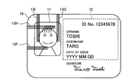
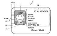
- FIG. 1 is an external front view of the recording medium (forgery / forgery prevention medium) of the first embodiment in a state where information is recorded.
- FIG. 2 is an explanatory diagram of a detailed configuration of the recording medium according to the first embodiment.
- FIG. 3 is a partially enlarged explanatory view when viewed from the end face of the recording medium according to the modification of the first embodiment.
- FIG. 4 is an explanatory diagram of a correspondence table of an information recording example according to a modification of the first embodiment.
- FIG. 5 is an explanatory diagram of a detailed configuration of the recording medium according to the second embodiment.
- FIG. 6 is an explanatory diagram of the coloring principle in the monochromatic color development of the second embodiment.
- FIG. 1 is an external front view of the recording medium (forgery / forgery prevention medium) of the first embodiment in a state where information is recorded.
- FIG. 2 is an explanatory diagram of a detailed configuration of the recording medium according to the first embodiment.
- FIG. 3 is
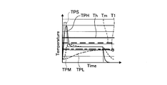
- FIG. 7 is an explanatory diagram of temperature control during monochromatic color development in the second embodiment.
- FIG. 8 is an explanatory diagram of an example of laser irradiation conditions.
- FIG. 9 is a schematic block diagram of the laser recording apparatus according to the embodiment.
- FIG. 10 is an explanatory diagram of the relationship between the amount of energy and the input time for causing each coloring layer to develop a color independently.
- FIG. 11 is an explanatory diagram of code allocation according to the first aspect of the second embodiment.
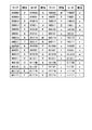
- FIG. 12 is an explanatory diagram of a correspondence table of an information recording example in the case of code allocation according to the first aspect of the second embodiment.
- FIG. 13 is an explanatory diagram of code allocation according to the second mode of the second embodiment.
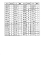
- FIG. 14 is an explanatory diagram of a correspondence table of an information recording example in the case of code allocation according to the second mode of the second embodiment.
- FIG. 15 is an explanatory diagram of code allocation according to the third aspect of the second embodiment.
- FIG. 16 is an explanatory diagram of a correspondence table of an information recording example in the case of code allocation according to the third aspect of the second embodiment.
- FIG. 17 is an explanatory diagram of code allocation according to the fourth aspect of the second embodiment.
- FIG. 18 is an explanatory diagram of a correspondence table of an example of information recording in the case of code allocation according to the fourth aspect of the second embodiment.
- FIG. 19 is an explanatory diagram (No. 1) of temperature control during mixed color development in the second embodiment.
- FIG. 20 is an explanatory diagram (No.
- FIG. 21 is an explanatory diagram of a detailed configuration of a recording medium according to the third embodiment.
- FIG. 22 is an explanatory diagram of another detailed configuration of the recording medium of the third embodiment.
- FIG. 23 is an explanatory diagram of still another detailed configuration of the recording medium of the third embodiment.
- FIG. 24 is an explanatory diagram of still another detailed configuration of the recording medium of the third embodiment.
- FIG. 25 is an explanatory diagram of still another detailed configuration of the recording medium of the third embodiment.
- FIG. 26 is an explanatory diagram of a detailed configuration of the recording medium according to the fourth embodiment.
- FIG. 27 is an explanatory diagram of code allocation according to the first aspect of the fourth embodiment.
- FIG. 28 is an explanatory diagram of a correspondence table of an example of information recording in the case of code allocation according to the first aspect of the fourth embodiment.
- FIG. 29 is an explanatory diagram of code allocation according to the second mode of the fourth embodiment.
- FIG. 30 is an explanatory diagram of a correspondence table of an example of information recording in the case of code allocation according to the second aspect of the fourth embodiment.
- FIG. 31 is an explanatory diagram of code allocation according to the third aspect of the fourth embodiment.
- FIG. 32 is an explanatory diagram of a part of the correspondence table of the information recording example (in the case where the upper 4 bits are 0001) in the case of code allocation according to the third aspect of the fourth embodiment.
- FIG. 33 is an explanatory diagram of a recording medium according to the first aspect of the fifth embodiment.
- FIG. 34 is an explanatory diagram of a recording medium according to the second aspect of the fifth embodiment.
- FIG. 35 is an explanatory diagram of a recording medium according to the third aspect of the fifth embodiment.
- FIG. 36 is a schematic configuration diagram of a recording medium according to the sixth embodiment.
- FIG. 37 is an external view of a recording medium according to the sixth embodiment.
- FIG. 38 is an explanatory diagram when invisible information is recorded on the recording medium shown in FIG.
- FIG. 39 is an explanatory diagram when invisible information is recorded on the recording medium shown in FIG.
- FIG. 40 is a schematic block diagram of the collation device.
- FIG. 1 is an external front view of the recording medium (forgery / forgery prevention medium) of the first embodiment in a state where information is recorded.
- the recording medium 10 on which the information is recorded is roughly divided into an image forming area 11 for recording an image, a specific information recording area 12 in which specific information such as ID information, name, and issue date is recorded, and prevention of falsification. Therefore, the forgery / alteration prevention information recording unit 13AR in which the forgery / alteration prevention information is recorded is provided.
- the forgery / alteration prevention information recording unit 13AR includes not only the surface 10S of the recording medium 10 but also the end face 10X of the recording medium 10 viewed from the direction of arrow A in FIG.
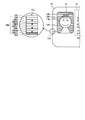
- FIG. 2 is an explanatory diagram of a detailed configuration of the recording medium according to the first embodiment.
- a number of fine lines 13X are arranged in parallel to form a background color (for example, gray).
- a part of the line 13X, specifically, the lines 13A to 13E are formed so as to extend to the end face 10X of the recording medium 10.
- the inside of the round frame is a partially enlarged view when the end face 10 ⁇ / b> X is viewed from the arrow A direction of the recording medium 10.
- a coloring layer 10B and a protective layer 10C as a surface layer are sequentially laminated on a base material 10A.
- a line (security line) 13A that is a part of the line 13X is formed so as to be visible from the direction of arrow A.
- the security line is recorded on the recording medium 10 for the purpose of preventing forgery and alteration, and consequently for authenticity determination, to the user of the recording medium 10 or a third party (except for the security administrator), Alternatively, it is a line for recording information so that the recorded content cannot be easily decoded.
- the marking surface of the recording medium 10 is the same. It can be seen that there is a high possibility that it has not been falsified or altered.
- the positions of all the lines 13A to 13E when observed from the surface 10S of the recording medium 10 and the positions of all the lines 13A to 13E when observed from the end face 10X of the recording medium 10 may coincide with each other. For example, it can be confirmed that there is a higher possibility that the stamp surface of the recording medium 10 has not been falsified or altered.
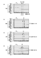
- FIG. 3 is a partially enlarged explanatory view when viewed from the end face of the recording medium according to the modification of the first embodiment.
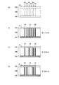
- the information recording position P1 is the recording position of the start flag 14 indicating the information recording start position
- the information recording position P6 is the recording position of the end flag 16 indicating the information recording end position.
- the four information recording positions P2 to P5 are information recording positions where 1-bit information can be recorded, and a code represented by 4 bits as a whole is recorded.
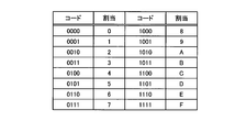
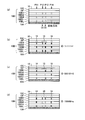
- FIG. 4 is an explanatory diagram of a correspondence table of an information recording example according to a modification of the first embodiment.
- any one of 16 codes (hexadecimal 0 to F) represented by 4 bits can be recorded as information code 15 at information recording positions P2 to P5. .
- a line is always recorded as the start flag 14 at the information recording position P1
- a line is always recorded as the end flag 16 at the information recording position P6.
- the information recording position P2 with a line
- the information recording position P3 with a line
- the information recording position P4 with a line
- the information recording position P5 with a line.
- the value of the information code 15 “1111”, it can be seen from the table of FIG. 4 that “F” is recorded.
- the information recording position P2 no line
- the information recording position P3 with a line
- the information recording position P4 no line
- the information recording position P5 with a line.
- the information code 15 “0101”, and it can be seen that “5” is recorded as the value of the information code 15 from the table of FIG.
- the information recording position P2 with a line
- the information recording position P3 without a line
- the information recording position P4 without a line
- the ID number is an 8-digit numerical value
- the ID number can be recorded. Of these, eight are used as the start flag 14 and the other eight are used as the end flag, so the remaining 32 (maximum value) represent the ID number.
- the thickness of the line 13X is approximately 85 ⁇ m or less, which is equal to or less than 300 lpi (line per inch). If recording with this fineness, the human visual resolution is exceeded, so the concealment is improved. In this case, there is no theoretical lower limit to the thickness of the line to be recorded. However, as the line width becomes thinner, the enlargement magnification increases in the cross-sectional observation at the time of authenticity determination. Therefore, there is a trade-off between concealment and convenience (easiness) for authenticity determination.
- the line width at the time of recording can be arbitrarily determined in consideration of the performance of the printing apparatus (recording apparatus) and the convenience at the time of authenticity determination.
- the line width of the line 13X is not limited to this as long as the line 13X is recorded from the image forming area 11 to the end face 10X without any problem even if it is easily revealed.
- the line 13X is used as the background of the image recording area and the line width is set to 85 ⁇ m, if the size of the image forming region 11 is, for example, 20 mm ⁇ 27.5 mm, even if the width is 20 mm, approximately 240 It is possible to record a line 13X, and in the case of the above example, it is possible to record 32-digit information.
- the thickness of the coloring layer 10B is preferably 1 ⁇ m or more and 700 ⁇ m or less. This is because if the thickness of the color forming layer 10B is less than 1 ⁇ m, it is difficult to observe the end face 10X of the recording medium 10 with a simple magnifier such as a loupe. Further, if the thickness of the coloring layer 10B exceeds 700 ⁇ m, the recording medium 10 exceeds 0.7 mm which is the thickness of a standard card such as a credit card.
- the thickness of the color forming layer 10B is more preferably 20 ⁇ m or less. If the thickness is 20 ⁇ m or less, the thickness of the line on the end surface 10X of the recording medium 10 is 20 ⁇ m or less, so that it is less than the dot diameter formed by a general and inexpensive printer such as an ink jet. This is because forgery, such as printing to 10X, is difficult and expensive, and the effect of preventing forgery / alteration is enhanced.
- the recording medium 10 includes the base material 10A, the coloring layer 10B, and the protective layer 10C as the surface layer.
- the base material 10A will be described.
- the base material 10A polyethylene terephthalate (PET), polyvinyl chloride (PVC), polycarbonate (PC), polyester, etc., which are generally used as card, paper, and film materials can be used.
- PET polyethylene terephthalate
- PVC polyvinyl chloride
- PC polycarbonate
- polyester etc., which are generally used as card, paper, and film materials can be used.
- paper (paper) and resin materials described in Japanese Patent No. 3889431, Japanese Patent No. 4215817, Japanese Patent No. 4329744, Japanese Patent No. 4391286, and the like can be used.
- the term “transparent” means that the light transmittance in the visible light region is 30% or more on average in the visible light region.
- the coloring layer 10B will be described.
- the energy absorbers described in Japanese Patent No. 3889431, Japanese Patent No. 4215817, Japanese Patent No. 4329744, and Japanese Patent No. 4391286 are used.
- a resin containing 0.001 to 5 parts by weight of an energy absorber with respect to 100 parts by weight of the resin can be used.
- the energy absorber is at least one selected from the group consisting of carbon black, simple metal, metal salt, metal hydroxide, metal oxide, metal sulfide, carbonate and metal silicate. It is possible to use seeds. Moreover, iron, zinc, tin, nickel, copper, silver, gold etc. are mentioned as a metal simple substance as an energy absorber.
- metal salts as energy absorbers include copper carbonate, nickel carbonate, manganese carbonate, cobalt carbonate, lanthanum nitrate, magnesium nitrate, manganese nitrate, iron nitrate, cadmium nitrate, zinc nitrate, cobalt nitrate, lead nitrate, nitric acid Nickel, copper nitrate, palladium nitrate, lanthanum nitrate, magnesium acetate, manganese acetate, cadmium acetate, zinc acetate, cobalt acetate, lead acetate, nickel acetate, copper acetate, palladium acetate, copper chloride, iron chloride, cobalt chloride, nickel chloride, Silver chloride, zinc chloride, copper phosphate, iron phosphate, cobalt phosphate, copper pyrophosphate, copper sulfate, iron sulfate, cobalt sulfate, copper oxalate, iron o
- metal hydroxides as energy absorbers include copper hydroxide, aluminum hydroxide, magnesium hydroxide, zinc hydroxide, antimony hydroxide, cobalt hydroxide, nickel hydroxide, iron hydroxide, lanthanum hydroxide Etc.
- Metal oxides include zinc oxide, magnesium oxide, aluminum oxide, alumina, iron oxide, iron black, titanium oxide, silicon oxide, antimony trioxide, cobalt oxide, lead oxide, tin oxide, indium oxide, manganese oxide, molybdenum oxide , Nickel oxide, copper oxide, palladium oxide, lanthanum oxide, antimony doped tin oxide (ATO), indium doped tin oxide (ITO), synthetic zeolite, natural zeolite, copper-molybten complex oxide (42-903A, Tocan Materials Technology Co., Ltd.).
- a metal oxide as an energy absorber mica, montmorillonite, smectite, etc. having a layered structure can be used.
- the metal sulfide as the energy absorber include zinc sulfide and cadmium sulfide.
- carbonates as energy absorbers include calcium carbonate, and metal silicates include alumina silicate, alumina containing iron silicate (mica), hydrous alumina silicate (kaolin), magnesium silicate ( Talc), calcium silicate, magnesium silicate and the like.
- metal silicates include alumina silicate, alumina containing iron silicate (mica), hydrous alumina silicate (kaolin), magnesium silicate ( Talc), calcium silicate, magnesium silicate and the like.
- a leuco dye instead of the energy absorber, a leuco dye, a leuco dye or other temperature indicating material that develops a color exceeding a certain threshold temperature may be used.
- a leuco dye instead of the energy absorber, a leuco dye, a leuco dye or other temperature indicating material that develops a color exceeding a certain threshold temperature may be used.
- any acidic substance used as an electron acceptor in a heat-sensitive recording material can be used, for example, inorganic substances such as activated clay, acidic clay, inorganic acids, aromatic carboxylic acids, anhydrides thereof or the like Examples include metal salts, organic sulfonic acids, other organic acids, and organic developers such as phenolic compounds, among which phenolic compounds are preferred.
- Specific examples include bis-3-allyl-4-hydroxyphenylsulfone, polyhydroxystyrene, zinc salt of 3,5-di-t-butylsalicylic acid, zinc salt of 3-octyl-5-methylsalicylic acid, phenol, 4-phenylphenol, 4-hydroxyacetophenone, 2,2'-dihydroxydiphenyl, 2,2'-methylenebis (4-chlorophenol), 2,2'-methylenebis (4-methyl-6-tert-butylphenol), 4 , 4'-isopropylidenediphenol (also known as bisphenol A), 4,4'-isopropylidenebis (2-chlorophenol), 4,4'-isopropylidenebis (2-methylphenol), 4,4'-ethylene Bis (2-methylphenol), 4,4'-thiobis (6-tert-butyl-3-methylphenol) 1,2-bis (4-hydroxyphenyl) -cyclohexane, 2,2'-bis (4-hydroxyphenyl) -n-heptane
- PET polyethylene terephthalate
- PVC polyvinyl chloride
- PC polycarbonate
- polyester or the like, which is generally used as a card, paper, or film material.
- paper and resin materials described in Japanese Patent No. 3889431, Japanese Patent No. 4215817, Japanese Patent No. 4329744, and Japanese Patent No. 4391286 can be used.
- polyethylene terephthalate PETG
- PETG polycyclohexane 1,4-dimethylphthalate
- PCT polystyrene
- PS polymethyl methacrylate
- MABS transparent ABS
- PP polypropylene
- PE Polyethylene
- PVA polyvinyl alcohol
- SBR styrene butadiene copolymer
- acrylic resin acrylic modified urethane resin, styrene / acrylic resin, ethylene / acrylic resin, urethane resin, rosin modified maleic resin, vinyl chloride / acetic acid Vinyl copolymers, polyvinyl acetal resins, polyamide resins, cellulose resins such as hydroxyethyl cellulose, hydroxypropyl cellulose, nitrocellulose, polyolefin resins, polyamide resins, raw Disintegrable resin, cellulose resin or the like other resins, paper substrate, a metal material, etc.
- A-PET polyethylene terephthalate
- PETG polycyclohe
- the protective layer 10C needs to be able to visually recognize the contents recorded on the coloring layer 10B, it is desirable to use a transparent resin.
- transparent means that the light transmittance in the visible light region is 30% or more on average in the visible light region.
- the protective layer 10C needs to be a material that transmits the wavelength region of the laser light to be used.
- the wavelength includes 1064 nm which is a wavelength of YAG, YVO 4 laser, and the like, and harmonics thereof such as 532 nm, 355 nm and 266 nm.
- a semiconductor laser or the like since it is not a single wavelength, it needs to be a material that transmits a wavelength in a certain range, for example, a region of 700 to 1200 nm.
- the positions of all the lines 13X when observed from the surface 10S of the recording medium 10 and the observation from the end face 10X of the recording medium 10 are observed. If the positions of all the lines 13X coincide with each other, it can be confirmed that there is a higher possibility that the stamp surface of the recording medium 10 is not falsified or altered.
- the color forming layer 10B is composed of one layer, but in the second embodiment, the color forming layer 10B has a plurality of different colors. It is an embodiment in the case of providing the coloring layer.
- FIG. 5 is an explanatory diagram of a detailed configuration of the recording medium according to the second embodiment.
- the plurality of coloring layers for example, three primary colors in printing such as cyan (C), magenta (M), and yellow (Y) can be used.
- the outline of the marking surface is the same as that of FIG. 1 of the first embodiment, but a plurality of colors are observed on the cross section of the medium as shown in FIG.
- the description will be made using heat, that is, temperature, which is one of the forms of input energy.
- the principle of the second embodiment will be described.
- at least heat generated on the protective layer 10C by laser irradiation is conducted to the plurality of color forming layers constituting the color forming layer 10B, and the temperature of each layer changes due to the laser.
- the color development in the plurality of color development layers is controlled by controlling according to how heat is applied, that is, controlling the temperature according to the laser irradiation conditions.
- the recording medium 10 includes a low temperature coloring layer 10BL, a first spacer layer 10BS1, a medium temperature coloring layer 10BM, a second spacer layer 10BS2, a high temperature on a base material 10A as shown in a circle in FIG.
- the coloring layer 10BH, the functional layer 10F, and the protective layer 10C are laminated in this order.
- the low temperature coloring layer 10BL, the medium temperature coloring layer 10BM, and the high temperature coloring layer 10BH constitute a heat-sensitive recording layer on which image recording is performed
- the first spacer layer 10BS1 and the second spacer layer 10BS2 perform heat insulation and heat transfer. It constitutes an intermediate layer.
- the base material 10A holds the low temperature coloring layer 10BL, the first spacer layer 10BS1, the medium temperature coloring layer 10BM, the second spacer layer 10BS2, the high temperature coloring layer 10BH, the functional layer 10F, and the protective layer 10C.
- the low temperature coloring layer 10BL is a layer including a temperature indicating material as a heat sensitive material that develops color when its temperature becomes equal to or higher than the first threshold temperature Tl.
- the first threshold temperature Tl of the low temperature coloring layer 10BL is set, for example, in the range of 60 ° C. to 140 ° C.
- the first spacer layer 10BS1 is a layer that provides a thermal barrier when the low temperature coloring layer 10BL is not colored, and suppresses heat transfer from the medium temperature coloring layer 10BM to the low temperature coloring layer 10BL.
- the intermediate temperature coloring layer 10BM is a layer including a temperature indicating material as a heat sensitive material that develops color when the temperature becomes equal to or higher than the second threshold temperature Tm (> Tl).
- the second threshold temperature Tm of the intermediate temperature coloring layer 10BM is set in the range of 100 ° C. to 200 ° C., for example.
- the second spacer layer 10BS2 is a layer that provides a thermal barrier when the medium temperature coloring layer 10BM is not colored, and suppresses heat transfer from the high temperature coloring layer 10BH to the medium temperature coloring layer 10BM.
- the high-temperature coloring layer 10BH is a layer containing a temperature indicating material as a heat-sensitive material that develops color when the temperature is equal to or higher than a third threshold temperature Th (> Tm).
- the third threshold temperature Th of the high temperature coloring layer 10BH is set, for example, in the range of 150 ° C. to 270 ° C.
- the functional layer 10F is a layer provided according to a required function. Specific functions of the functional layer 10F include insertion of anti-counterfeiting items such as holograms, lenticular lenses, microarray lenses, ultraviolet excitation type fluorescent inks, insertion of internal protection items such as ultraviolet cut layers, or the functions of both. Can be used.
- the protective layer 10C is a layer for protecting the low temperature coloring layer 10BL, the first spacer layer 10BS1, the medium temperature coloring layer 10BM, the second spacer layer 10BS2, the high temperature coloring layer 10BH, and the functional layer 10F.
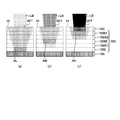
- FIG. 6 is an explanatory diagram of the coloring principle in the monochromatic color development of the second embodiment.
- the functional layer 10F is not provided for easy understanding.
- FIG. 6A is an explanatory diagram of the principle when the low temperature coloring layer 10BL is individually colored.
- FIG. 6B is a diagram for explaining the principle when the intermediate temperature coloring layer 10BM is individually colored.
- FIG. 6C is a diagram for explaining the principle when the high-temperature coloring layer 10BH is individually colored.
- FIG. 7 is an explanatory diagram of temperature control during monochromatic color development in the second embodiment.
- FIG. 7A is an explanatory diagram of temperature control when the low temperature coloring layer 10BL is individually colored.
- the temperature of the surface 10S of the recording medium 10 is indicated by a temperature TPS.
- FIG. 7B is an explanatory diagram of temperature control when the intermediate temperature coloring layer 10BM is individually colored.
- FIG. 7C is an explanatory diagram of temperature control when the high temperature coloring layer 10BH is individually colored.
- FIG. 8 is an explanatory diagram of an example of laser irradiation conditions.
- the power density and the recording time of the laser beam for coloring each of the low temperature coloring layer 10BL, the medium temperature coloring layer 10BM, and the high temperature coloring layer 10BH are set as power densities PD1, PDm, and PDh, respectively.
- time tl, tm, and th are given, PDl ⁇ PDm ⁇ PDh and th ⁇ tm ⁇ tl Set to satisfy the conditions.
- ⁇ 1 and ⁇ 2 are appropriately set in advance according to the materials constituting the low temperature coloring layer 10BL, the medium temperature coloring layer 10BM, and the high temperature coloring layer 10BH.
- the values of ⁇ 1 and ⁇ 2 are appropriately set in advance according to the materials constituting the low temperature coloring layer 10BL, the medium temperature coloring layer 10BM, and the high temperature coloring layer 10BH.
- the power density PDl is relatively smallest and the recording time tl is relatively largest.
- the temperature of the intermediate temperature coloring layer 10BM does not exceed the second threshold temperature Tm and the high temperature coloring layer 10BM does not exceed the second threshold temperature Tm at the stage where heat is transmitted to the high temperature coloring layer 10BH and the intermediate temperature coloring layer 10BM.
- the temperature of the low temperature coloring layer 10BL can exceed the first threshold temperature Tl while the temperature of 10BH does not exceed the third threshold temperature Th.
- the power density PDh is relatively largest and the recording time th is relatively shortest.
- the temperature of the intermediate temperature coloring layer 10BM and the threshold value of the low temperature coloring layer 10BL are not exceeded. Only the color developing layer 10BH can exceed the threshold temperature.
- the power density PDm and the recording time tm are set to relatively intermediate values as described above.
- the medium temperature coloring is performed without exceeding the threshold temperature of the high temperature coloring layer 10BH and the threshold temperature of the low temperature coloring layer 10BL. Only the layer 10BM can exceed the threshold temperature.
- each layer corresponding to the three primary colors can be selectively developed, full-color recording combining the three primary colors becomes possible. Furthermore, according to the method of the second embodiment, the three primary colors can be recorded in the stacking direction of the layers of the recording medium 10. For this reason, compared with the case where three primary colors are arrange
- FIG. 9 is a schematic block diagram of the laser recording apparatus according to the embodiment.
- the laser recording apparatus 100 effectively emits a laser beam LB for recording to the recording medium 10 placed on the recording stage 101, and a laser beam LB emitted from the laser head unit 102.
- the laser head unit 102 includes the spot control unit 102A as an optical system that controls the focal position of the laser beam LB and the spot diameter of the laser beam LB under the control of the control unit 104.
- control unit 104 controls the power density, irradiation time, focal position, spot diameter, and the like of the laser light LB emitted from the laser head unit 102 based on a control program stored in advance, so that the low temperature coloring layer 10BL, Of the intermediate temperature coloring layer 10BM and the high temperature coloring layer 10BH, one or more desired coloring layers can be colored.
- FIG. 10 is an explanatory diagram of the relationship between the amount of energy and the input time for causing each coloring layer to develop a color independently.
- the region satisfying the energy amount and the input time for coloring the low temperature coloring layer 10BL alone is indicated by the region AL
- the energy amount and the input time for coloring the medium temperature coloring layer 10BM alone is indicated by the region AL
- a region satisfying the above is indicated by a region AM
- a region satisfying the amount of energy and the input time for causing the high temperature coloring layer 10BH to independently develop color is indicated by a region AH.
- the arrangement of the line 13X extending to the end face 10X of the recording medium 10 and the coloring layer for color development are changed for each medium in order to improve the anti-counterfeiting effect and the accuracy of authenticity determination. It is possible to code and embed specific information.
- code and embed specific information it is possible to code and embed specific information.
- four modes of code allocation will be described as an example. Note that the present invention is not limited to these four modes, and various allocation modes are possible.
- FIG. 11 is an explanatory diagram of code allocation according to the first aspect of the second embodiment.
- FIG. 11 shows a partially enlarged explanatory view when viewed from the end face of the recording medium when the code assignment of the first mode of the second embodiment is performed.
- the information recording position P1 is a recording position of the start flag 14 indicating the information recording start position
- the information recording position P6 is the information recording end position. Is the recording position of the end flag 16 indicating.
- the four information recording positions P2 to P5 are information recording positions where 1-bit information can be recorded, and a code represented by 4 bits as a whole is recorded.
- the information code is read from left to right as shown in FIG.
- FIG. 12 is an explanatory diagram of a correspondence table of an information recording example in the case of code allocation according to the first aspect of the second embodiment.
- 16 codes (hexadecimal numbers) represented by 4 bits corresponding to the same code are all included in the low temperature coloring layer 10BL, the medium temperature coloring layer 10BM, and the high temperature coloring layer 10BH of the recording medium 10. 0 to F) can be recorded as information code 15 at information recording positions P2 to P5. That is, in the first aspect, one code is recorded for the low temperature coloring layer 10BL, the medium temperature coloring layer 10BM, and the high temperature coloring layer 10BH as a whole of the recording medium 10.
- the information recording position P2 no line
- the information recording position P3 the line is present
- Information recording position P4 no line
- information recording position P5 line present
- the information recording position P2 line
- the information recording position P3 no line
- the recording position P4 no line
- the information recording position P5 the line
- the information code 15 “1001”.
- the value of the information code 15, “9” is recorded from the table of FIG. I understand.
- start flag 14 and the end flag 16 need only serve as a mark in which the information code 15 is embedded between the flags. (Single color or mixed color).
- the information code 15 is black (K) due to a mixture of cyan (C), magenta (M), and yellow (Y) when viewed from the surface 10S of the recording medium 10. From the end surface 10X of the recording medium 10, it can be seen that cyan (C), magenta (M), and yellow (Y) are separately colored.
- FIG. 13 is an explanatory diagram of code allocation according to the second aspect of the second embodiment.
- FIG. 13 shows a partially enlarged explanatory view when viewed from the end face of the recording medium when code allocation according to the second mode of the second embodiment is performed.
- four information recording positions P11 to P14 are set in each of the low temperature coloring layer 10BL, the medium temperature coloring layer 10BM, and the high temperature coloring layer 10BH of the recording medium 10.
- the information recording position P11 is the recording position of the start flag 14 indicating the information recording start position
- the information recording position P14 is the information recording end position. Is the recording position of the end flag 16 indicating.
- the information recording positions P12 to P13 are information recording positions at which 3 bits of information can be recorded and a code represented by 6 bits as a whole is recorded.
- the information code is read by first setting the information recording position P12 at the high temperature coloring layer 10BH ⁇ the medium temperature coloring layer 10BM ⁇ the low temperature coloring layer 10BL.
- the information recording position P13 is set so as to be read from the top to the bottom, and then the information recording position P13 is read from the top to the bottom like the high temperature coloring layer 10BH ⁇ the medium temperature coloring layer 10BM ⁇ the low temperature coloring layer 10BL.
- FIG. 14 is an explanatory diagram of a correspondence table of an information recording example in the case of code allocation according to the second mode of the second embodiment.
- the information recording position P12 of the high temperature coloring layer 10BH is a line
- the information recording position P12 of the medium temperature coloring layer 10BM is a line
- the information recording of the low temperature coloring layer 10BL is performed.
- the information recording position P12 of the high temperature coloring layer 10BH no line
- the information recording position P12 of the medium temperature coloring layer 10BM no line
- P12 no line
- information recording position P13 of the high temperature coloring layer 10BH with line
- information recording position P13 of the medium temperature coloring layer 10BM no line
- information recording position P13 of the low temperature coloring layer 10BL with line
- information code 15 As the value of “000101”, it can be seen from the table of FIG. 14 that “5” is recorded.
- the information recording position P12 of the high temperature coloring layer 10BH there is a line
- the information recording position P12 of the intermediate temperature coloring layer 10BM is not a line
- information recording position P13 of the high temperature coloring layer 10BH with line
- information recording position P13 of the medium temperature coloring layer 10BM no line
- information recording position P13 of the low temperature coloring layer 10BL no line
- information code 15 As the value of “100100”, it can be seen that “a” is recorded from the table of FIG.
- FIG. 15 is an explanatory diagram of code allocation according to the third mode of the second embodiment.
- the third mode is different in that the start flag 14 and the end flag 16 used in the first mode and the second mode are not used.
- FIG. 15 shows a partially enlarged explanatory view when viewed from the end face of the recording medium when code allocation according to the third aspect of the second embodiment is performed.
- two information recording positions P21 and P22 are set in each of the low temperature coloring layer 10BL, the medium temperature coloring layer 10BM, and the high temperature coloring layer 10BH of the recording medium 10, and each of them is 3 Bit information can be recorded, and an information recording position where a code represented by 6 bits as a whole is recorded.
- the information code is read by first setting the information recording position P21 at the high temperature coloring layer 10BH ⁇ the intermediate temperature coloring layer 10BM ⁇ the low temperature coloring layer 10BL.
- the information recording position P22 is set to be read from top to bottom in the order of reading from the top to the bottom, and subsequently the information recording position P22 in the order of the high-temperature coloring layer 10BH ⁇ the medium-temperature coloring layer 10BM ⁇ the low-temperature coloring layer 10BL.
- FIG. 16 is an explanatory diagram of a correspondence table of an information recording example in the case of code allocation according to the third aspect of the second embodiment.
- the information recording position P21 of the high temperature coloring layer 10BH is a line
- the information recording position P21 of the medium temperature coloring layer 10BM is a line
- the information recording of the low temperature coloring layer 10BL is performed.
- Position P21 There is a line
- Information recording position P22 of the high temperature coloring layer 10BH There is a line
- Information recording position P22 of the medium temperature coloring layer 10BM There is a line
- Information recording position P22 There is a line
- P21 no line
- information recording position P22 of the high temperature coloring layer 10BH with line
- information recording position P22 of the medium temperature coloring layer 10BM no line
- information recording position P22 of the low temperature coloring layer 10BL with line
- information code 15 As the value of “100101”, it can be seen that “P” is recorded from the table of FIG.
- the information recording position P21 of the high temperature coloring layer 10BH with a line
- the information recording position P21 of the intermediate temperature coloring layer 10BM no line
- the information recording position of the low temperature coloring layer 10BL no line
- P21 no line
- information recording position P22 of the high temperature coloring layer 10BH with line
- information recording position P22 of the medium temperature coloring layer 10BM no line
- information recording position P22 of the low temperature coloring layer 10BL no line
- information code 15 As the value of “100100”, it can be seen that “O” is recorded from the table of FIG.
- FIG. 17 is an explanatory diagram of code allocation according to the fourth aspect of the second embodiment. Also in the fourth mode, the start flag 14 and the end flag 16 are not used as in the third mode. FIG. 17 shows a partially enlarged explanatory view when viewed from the end face of the recording medium when code allocation according to the fourth aspect of the second embodiment is performed.
- two information recording positions P21 and P22 are set in each of the low temperature coloring layer 10BL, the medium temperature coloring layer 10BM, and the high temperature coloring layer 10BH of the recording medium 10, and each of them is 3 Bit information can be recorded, and an information recording position where a code represented by 6 bits as a whole is recorded.
- the information code is read by first setting the information recording position P21 at the low temperature coloring layer 10BL ⁇ the intermediate temperature coloring layer 10BM ⁇ the high temperature coloring layer 10BH.
- the information recording position P22 is set so as to be read from the bottom to the top, and then the information recording position P22 is read from the bottom to the top in the order of the low temperature coloring layer 10BL ⁇ the medium temperature coloring layer 10BM ⁇ the high temperature coloring layer 10BH.
- FIG. 18 is an explanatory diagram of a correspondence table of an example of information recording in the case of code allocation according to the fourth aspect of the second embodiment.
- the information recording position P21 of the low temperature coloring layer 10BL no line
- the information recording position P21 of the medium temperature coloring layer 10BM the line
- the information recording position of the high temperature coloring layer 10BH there is a line
- the information recording position P22 of the low temperature coloring layer 10BL is the line
- the information recording position P22 of the intermediate temperature coloring layer 10BM is the line
- the information recording position P22 of the high temperature coloring layer 10BH is the line
- the information code As the value of 15 “011111”, it can be seen from the table of FIG. 18 that “9” is recorded.
- the information recording position P21 of the low temperature coloring layer 10BL no line
- the information recording position P21 of the medium temperature coloring layer 10BM no line
- the information recording position of the high temperature coloring layer 10BH There is a line
- information recording position P22 of the low temperature coloring layer 10BL There is a line
- information recording position P22 of the medium temperature coloring layer 10BM No line
- Information recording position P22 of the high temperature coloring layer 10BH There is a line
- information code 15 It can be seen from the table of FIG. 18 that “6” is recorded as the value of “001101”.
- the information recording position P21 of the low temperature coloring layer 10BL no line
- the information recording position P21 of the medium temperature coloring layer 10BM no line
- the information recording position of the high temperature coloring layer 10BH There is a line
- information recording position P22 of the low temperature coloring layer 10BL No line
- Information recording position P22 of the medium temperature coloring layer 10BM No line
- Information recording position P22 of the high temperature coloring layer 10BH There is a line
- information code 15 It can be seen from the table of FIG. 18 that “0” is recorded as the value of “001001”.
- FIG. 19 is an explanatory diagram (No. 1) of temperature control during mixed color development in the second embodiment.
- the low temperature coloring layer 10BL is a cyan (C) coloring layer
- the medium temperature coloring layer 10BM is a magenta (M) coloring layer
- the high temperature coloring layer 10BH is a yellow (Y) coloring layer. It shall be.
- FIG. 19A shows the temperature control in the case where the medium temperature coloring layer 10BM, which is the magenta (M) coloring layer, and the high temperature coloring layer 10BH, which is the yellow (Y) coloring layer, are colored and red (R) is colored. It is explanatory drawing.
- FIG. 19B shows the temperature control when the low temperature coloring layer 10BL which is a coloring layer of cyan (C) and the medium temperature coloring layer 10BM which is a coloring layer of magenta (M) are colored and blue (B) is colored. It is explanatory drawing.
- the low-temperature coloring layer 10BL which is a cyan (C) coloring layer
- the medium-temperature coloring layer 10BM which is a magenta (M) coloring layer
- the high-temperature coloring layer 10BH which is a yellow (Y) coloring layer are colored. It is explanatory drawing of temperature control in the case of making it color black (K).
- the temperature TPL of the low temperature coloring layer 10BL is Laser irradiation conditions that do not exceed the first threshold temperature Tl, at the same time the temperature TPM of the intermediate temperature coloring layer 10BM exceeds the second threshold temperature Tm, and the temperature TPH of the high temperature coloring layer 10BH exceeds the third threshold temperature Th, ie, FIG.
- recording is performed in a temperature control state in which the laser irradiation time (horizontal axis) is within the time zone TB.
- the high temperature coloring layer 10BH which is the yellow (Y) coloring layer
- the low temperature coloring layer 10BL that is the cyan (C) coloring layer and the medium temperature coloring layer 10BM that is the magenta (M) coloring layer are colored and blue (B) is colored, the low temperature coloring is performed from the laser irradiation position.
- the high temperature coloring layer 10BH Recording is performed under a laser irradiation condition in which the temperature TPH of the laser beam does not exceed the third threshold temperature Th, that is, in a temperature control state in which the laser irradiation time (horizontal axis) falls within the time zone TB as shown in FIG. .
- the low temperature coloring layer 10BL that is a cyan (C) coloring layer and the medium temperature coloring layer 10BM that is a magenta (M) coloring layer can be colored, and blue (B) can be colored.
- the low temperature coloring layer 10BL which is a coloring layer of cyan (C)
- the medium temperature coloring layer 10BM which is a coloring layer of magenta (M)
- the high temperature coloring layer 10BH which is a coloring layer of yellow (Y)
- K black
- heat is transferred from the laser irradiation position to the low temperature coloring layer 10BL
- the temperature TPL of the low temperature coloring layer 10BL exceeds the first threshold temperature Tl
- the temperature TPM of the intermediate temperature coloring layer 10BM is the second threshold temperature Tm.
- the laser irradiation condition in which the temperature TPH of the high-temperature coloring layer 10BH exceeds the third threshold temperature Th that is, the laser irradiation time (horizontal axis) as shown in FIG.
- the low temperature coloring layer 10BL which is a coloring layer of cyan (C)
- the medium temperature coloring layer 10BM which is a coloring layer of magenta (M)
- the coloring layer of yellow (Y) The high temperature coloring layer 10BH can be colored, and black (K) can be colored.
- FIG. 20 is an explanatory diagram (No. 2) of temperature control during mixed color development in the second embodiment.
- FIG. 20 shows a low-temperature coloring layer 10BL that is a cyan (C) coloring layer and a high-temperature coloring layer 10BH that is a yellow (Y) coloring layer disposed via a medium-temperature coloring layer 10BM that is a magenta (M) coloring layer. It is explanatory drawing of the temperature control in the case of developing color and developing green (G).
- C cyan
- M magenta
- the temperature of the high-temperature coloring layer 10BH is first increased at a stroke to develop yellow (Y), and then the temperature of the intermediate-temperature coloring layer 10BM is lowered to some extent.
- green (G) can be developed.
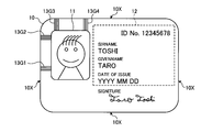
- FIG. 21 is an explanatory diagram of a detailed configuration of a recording medium according to the third embodiment.
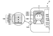
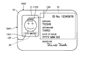
- the lines 13A to 13E extending to the end surface 10X of the recording medium 10 constitute the background portion 11A of the image in the image forming area 11 of the recording medium 10. It was formed by extending the line.
- the edge portion of the image recorded in the image forming area 11 of the recording medium 10 for example, in the case of FIG.
- the edge portion 11E1 corresponding to the boundary line or the hair of the subject is detected as the edge portion 11E2, and the line 13F or the line 13G having the same color as the color of the edge portion from the edge portions 11E1 and 11E2 (when these are single or plural lines) As well as the end faces 10X1 and 10X2 of the recording medium 10.
- the edge portion is a high-contrast portion such as a characteristic portion of an image, for example, the upper and lower ends of a face of a face photo, the end of clothes or hair, the outline of a face, etc.
- a part with high contrast is a part where a differential image is created based on the brightness data when the recorded image is converted to gray scale, and the rate of change in the brightness is relatively large in the differential image.
- the extending positions of the lines 13F and 13G extending to the end faces 10X1 and 10X2 of the recording medium 10 differ depending on the image recorded in the image forming area 11, and thus the recording medium 10
- FIG. 22 is an explanatory diagram of another detailed configuration of the recording medium of the third embodiment.
- the extended lines 13F, 13G, 13H, and 13I extend in both the longitudinal direction and the short direction of the recording medium 10, that is, both the end faces 10X1 and 10X2 of the recording medium 10, respectively. It is also possible to make it. By adopting such a configuration, it becomes necessary to perform two-dimensional alignment when performing falsification such as replacement of an image, so that falsification resistance is improved.
- FIG. 23 is an explanatory diagram of still another detailed configuration of the recording medium of the third embodiment. Since the edge portion with high contrast such as the outline of the face is usually a curve, as shown in FIG. 23, the lines extending to the end faces 10X1 and 10X2 of the recording medium 10 are also curved according to the shape of the edge portion.
- the edge portion with high contrast such as the outline of the face is usually a curve
- the lines extending to the end faces 10X1 and 10X2 of the recording medium 10 are also curved according to the shape of the edge portion.
- FIG. 24 is an explanatory diagram of still another detailed configuration of the recording medium of the third embodiment.
- FIG. 24 shows lines 13F1, 13G1, 13H1, and 13I1 extended from the eye position (or a group of lines formed from a plurality of lines) in both the longitudinal direction and the short direction of the recording medium 10, that is, the recording medium 10. This is an example in the case of extending to both of the end faces 10X1, 10X2.
- the line 13F1 and the line 13G1 intersect at the position of the right eye in the face image
- the line 13H1 and the line 13I1 intersect at the position of the left eye in the face image.
- the eyes are not located at the positions specified by the lines 13F1, 13G1, 13H1, and 13I1, and therefore it can be easily confirmed that the image is forged.
- FIG. 25 is an explanatory diagram of still another detailed configuration of the recording medium of the third embodiment.
- FIG. 25 shows lines 13F2, 13G2, 13H2, and 13I2 extended from the position of the lips (or a group of lines composed of a plurality of lines) in both the longitudinal direction and the short direction of the recording medium 10, that is, the recording medium 10. This is an example in the case of extending to both of the end faces 10X1, 10X2.
- the line 13F2 and the line 13G2 intersect at positions that would be seen when the lips in the face image are viewed from the right side of the face, and the lines 13H2 and 13I2 represent the lips in the face image. It will intersect at a position that would be visible when viewed from the left side of the face.
- the high-temperature coloring that develops yellow (Y) is an embodiment in the case of using a recording medium further including an ultra-low temperature coloring layer 10BLL for coloring black (K). .
- FIG. 26 is an explanatory diagram of a detailed configuration of the recording medium according to the fourth embodiment. Also in the recording medium of the fourth embodiment, the heat generated by laser irradiation at least on the protective layer 10C is conducted to the plurality of color forming layers constituting the color forming layer 10B and the temperature of each layer changes. The color development in a plurality of color development layers is controlled by controlling the temperature according to the laser irradiation condition, that is, by controlling the temperature according to the laser irradiation conditions.
- the recording medium 10 includes an ultra-low temperature coloring layer 10BLL, a zeroth spacer layer 10BS0, a low temperature coloring layer 10BL, a first spacer layer 10BS1, an intermediate temperature on a base material 10A.
- the coloring layer 10BM, the second spacer layer 10BS2, the high temperature coloring layer 10BH, the functional layer 10F, and the protective layer 10C are laminated in this order, and the line 13J is recorded by these layers.
- the ultra low temperature coloring layer 10BLL, the low temperature coloring layer 10BL, the medium temperature coloring layer 10BM, and the high temperature coloring layer 10BH constitute a thermosensitive recording layer on which image recording is performed, and the 0th spacer layer 10BS0, the first spacer layer 10BS1 and the second spacer layer 10BS1.
- the spacer layer 10BS2 constitutes an intermediate layer that performs heat insulation and heat transfer.
- the ultra-low temperature color-developing layer 10BLL is a layer containing a temperature indicating material as a heat-sensitive material that develops color when its temperature reaches or exceeds the 0th threshold temperature Tll.
- the 0th threshold temperature Tll of the ultra-low temperature coloring layer 10BLL is set in the range of 40 ° C. to 90 ° C., for example.
- the 0th spacer layer 10BS0 is a layer that provides a thermal barrier when the ultra-low temperature coloring layer 10BLL is not colored, and suppresses heat transfer from the low-temperature coloring layer 10BL to the ultra-low temperature coloring layer 10BLL.
- the arrangement of the line 13X extending to the end surface 10X of the recording medium 10 and the coloring layer for color development are changed for each medium in order to improve the anti-counterfeit effect and the accuracy of authenticity determination. It is possible to code and embed specific information.
- three modes of code allocation will be described as an example. Note that the present invention is not limited to these three modes, and various allocation modes are possible.
- FIG. 27 is an explanatory diagram of code allocation according to the first aspect of the fourth embodiment.
- FIG. 27 shows a partially enlarged explanatory view when viewed from the end face of the recording medium when code allocation according to the first mode of the fourth embodiment is performed.
- FIG. 27A for example, six information recording positions P1 to P6 are provided in each of the ultra-low temperature coloring layer 10BLL, the low temperature coloring layer 10BL, the medium temperature coloring layer 10BM, and the high temperature coloring layer 10BH of the recording medium 10. Is set.
- the information recording position P1 is the recording position of the start flag 14 indicating the information recording start position
- the information recording position P6 is the information recording end position. Is the recording position of the end flag 16 indicating.
- the four information recording positions P2 to P5 are information recording positions at which 1-bit information can be recorded, and a code represented by 4 bits as a whole is recorded.
- the information code is read from left to right as shown in FIG.
- FIG. 28 is an explanatory diagram of a correspondence table of an example of information recording in the case of code allocation according to the first aspect of the fourth embodiment.
- 16 ultra-low temperature color developing layers 10BLL, low temperature color developing layers 10BL, medium temperature color developing layers 10BM and high temperature color developing layers 10BH of the recording medium 10 are all represented by 16 bits represented by 4 bits corresponding to the same code.
- Any one of the codes (hexadecimal 0 to F) can be recorded as information code 15 at information recording positions P2 to P5. That is, in the first aspect, one code is recorded for the ultra-low temperature coloring layer 10BLL, the low temperature coloring layer 10BL, the medium temperature coloring layer 10BM, and the high temperature coloring layer 10BH as a whole.
- the information recording position P2 line is present in all of the ultra-low temperature coloring layer 10BLL, the low temperature coloring layer 10BL, the intermediate temperature coloring layer 10BM, and the high temperature coloring layer 10BH.
- Position P3 with line
- information recording position P4 with line
- information recording position P5 with line
- information code 15 “1111” is recorded with “F” from the table of FIG. I understand that.
- the information recording position P2 no line
- P3 with line
- information recording position P4 without line
- information recording position P5 with line
- information code 15 “0101”
- the value of information code 15 is “5” from the table of FIG. You can see that it is recorded.
- the information code 15 is a mixed color of black (K), cyan (C), magenta (M), and yellow (Y) when viewed from the surface 10S of the recording medium 10. As a result, it is observed as a black line, and from the end surface 10X of the recording medium 10, it is possible to visually recognize a state in which black (K), cyan (C), magenta (M), and yellow (Y) are separately colored.
- FIG. 29 is an explanatory diagram of code allocation according to the second aspect of the fourth embodiment.
- FIG. 29 shows a partially enlarged explanatory view when viewed from the end face of the recording medium when code allocation according to the third aspect of the fourth embodiment is performed.
- FIG. 29A for example, six information recording positions P1 to P6 are set in the ultra-low temperature coloring layer 10BLL, the low temperature coloring layer 10BL, the medium temperature coloring layer 10BM, and the high temperature coloring layer 10BH of the recording medium 10. ing.
- 1 bit is assigned to the ultra-low temperature coloring layer 10BLL as the information recording position P2 and the information recording position P4 depending on the presence or absence of coloring, and the low temperature coloring layer 10BL.
- 1 bit is assigned to each of the medium temperature coloring layer 10BM and the high temperature coloring layer 10BH depending on the presence / absence of coloring as a whole (black (K) or no coloring as a mixed color) as the information recording position P3 and the information recording position P5.
- K black
- P5 4-bit information
- the color tone is different regardless of whether the ultra-low temperature color development layer 10BLL is colored or the low temperature color development layer 10BL, the medium temperature color development layer 10BM, and the high temperature color development layer 10BH are all color development. Since both of them are black (K), there is an advantage that the embedding of the information code is difficult to reveal and the falsification resistance is improved.
- the information code is read by the information recording position P2 of the ultra-low temperature coloring layer 10BLL ⁇ the low temperature coloring layer 10BL, the intermediate temperature coloring layer 10BM, and the high temperature coloring layer.
- FIG. 30 is an explanatory diagram of a correspondence table of an example of information recording in the case of code allocation according to the second aspect of the fourth embodiment.
- any one of 16 codes (hexadecimal 0 to F) represented by 4 bits can be recorded as information code 15 at information recording positions P2 to P5.
- the information recording position P2 of the ultra low temperature coloring layer 10BLL is a line, and the information recording positions are all in the low temperature coloring layer 10BL, the intermediate temperature coloring layer 10BM, and the high temperature coloring layer 10BH.
- P3 There is a line
- the information recording position P4 of the ultra-low temperature coloring layer 10BLL There is a line
- the information recording position P5 There is a line in all of the low temperature coloring layer 10BL, the medium temperature coloring layer 10BM, and the high temperature coloring layer 10BH
- the information code 15 As the value of “1111”, it can be seen from the table of FIG. 30 that “F” is recorded.
- the information recording position P2 of the ultra low temperature coloring layer 10BLL no line
- the information recording position P3 in all of the low temperature coloring layer 10BL, the medium temperature coloring layer 10BM, and the high temperature coloring layer 10BH. Line
- information recording position P4 of the ultra-low temperature coloring layer 10BLL No line
- information recording position P5 line in all of the low temperature coloring layer 10BL, medium temperature coloring layer 10BM, and high temperature coloring layer 10BH
- information code 15 " As the value of “0101”, it can be seen from the table of FIG. 30 that “5” is recorded.
- the information recording position P2 of the ultra-low temperature coloring layer 10BLL is a line
- the information recording position P3 in all of the low temperature coloring layer 10BL, the intermediate temperature coloring layer 10BM, and the high temperature coloring layer 10BH. No line
- information recording position P4 of the ultra low temperature coloring layer 10BLL No line
- information recording position P5 line in all of the low temperature coloring layer 10BL, medium temperature coloring layer 10BM and high temperature coloring layer 10BH
- information code 15 " As a value of “1001”, it can be seen from the table of FIG. 30 that “9” is recorded.
- start flag 14 and the end flag 16 need only serve as a mark in which the information code 15 is embedded between the flags. (Single color or mixed color).
- the information code 15 when viewed from the surface 10S of the recording medium 10, the information code 15 is colored black (K) or cyan (C), magenta (M), and yellow (Y). From the end face 10X of the recording medium 10, the state in which black (K), cyan (C), magenta (M), and yellow (Y) are colored can be visually recognized.
- FIG. 31 is an explanatory diagram of code allocation according to the third aspect of the fourth embodiment.
- FIG. 31 shows a partially enlarged explanatory view when viewed from the end face of the recording medium when the code assignment of the second mode of the fourth embodiment is performed.
- each of the ultra-low temperature coloring layer 10BLL, the low temperature coloring layer 10BL, the medium temperature coloring layer 10BM, and the high temperature coloring layer 10BH of the recording medium 10 has, for example, two information recording positions P21 and P22. Is set. In the information recording positions P21 and P22, 1-bit information can be recorded, and the information recording position is recorded with a code represented by 4 bits as a whole.
- the information code is read from the bottom to the top at the information recording position P21 and from the bottom to the top at the information recording position P22.
- a total of 8-bit information codes are to be read.
- the information recording position P21 and the information recording position P22 also serve as a start flag or an end flag, the ultra-low temperature coloring layer 10BLL and the low temperature coloring layer 10BL of the recording medium 10 at both the information recording position P21 and the information recording position P12.
- the information code is coded so that any one of the medium temperature coloring layer 10BM and the high temperature coloring layer 10BH is colored.
- the recording time (drawing time) of the line (security line) can be shortened by limiting the number of numbers 0 to 9 + five symbols to a total of 15 types.
- the information recording position P21 of the ultra-low temperature coloring layer 10BLL no line
- the information recording position P21 of the low temperature coloring layer 10BL no line
- information recording position P21 of the high temperature coloring layer 10BH with line
- information recording position P22 of the ultra low temperature coloring layer 10BLL with line
- information recording position P22 of the low temperature coloring layer 10BL with line
- the information recording position P21 of the ultra-low temperature coloring layer 10BLL no line
- the information recording position P21 of the low temperature coloring layer 10BL no line
- information recording position P21 of the high temperature coloring layer 10BH lined
- information recording position P22 of the ultra-low temperature coloring layer 10BLL lined
- information recording position P22 of the low temperature coloring layer 10BL no line
- information recording position P22 of the high-temperature coloring layer 10BH no line
- information code 15 “00011010” is recorded as “9” from the table of FIG. I understand.
- the information recording position P21 of the ultra-low temperature coloring layer 10BLL no line
- the information recording position P21 of the low temperature coloring layer 10BL no line
- information recording position P21 of the high temperature coloring layer 10BH lined
- information recording position P22 of the ultra-low temperature coloring layer 10BLL lined
- information recording position P22 of the low temperature coloring layer 10BL no line
- Information recording position P22 No line
- information recording position P22 of the high-temperature coloring layer 10BH line present
- information code 15 “00011001” is recorded as “8” from the table of FIG. I understand.
- an ID number (“12345678” in the case of FIG. 1) that can specify the owner of the recording medium 10 is specified as specific information. It is also possible to record as in the first embodiment.
- an image is formed on the recording medium 10 by causing the low temperature coloring layer 10BL, the medium temperature coloring layer 10BM, the high temperature coloring layer 10BH, and in addition, the ultra low temperature coloring layer 10BLL to color.
- the image forming area 11 and the line 13 as the security line are formed so as to reach the formed image in the image forming area 11, but from the viewpoint of preventing falsification, the end face 10X of the recording medium 10 It is only necessary that a line (security line) extending along the laminated surface of the coloring layer of the base material 10A is formed, and the presence or absence of the security line can be optically identified on the end surface 10X.
- FIG. 33 is an explanatory diagram of a recording medium according to the first mode of the fifth embodiment.
- the end of the line group (security line group) 13G1 to 13G4 composed of a plurality of lines 13X, which is different from the end face 10X, is positioned in the image forming area 11. Also good.
- the presence / absence of the security line and the information code can be identified optically on any of the end faces 10X, and the presence / absence of the optical security line can be optically detected from the surface 10S of the recording medium 10 as well.
- the information code can be identified, and confirmation of falsification becomes easy.
- FIG. 34 is an explanatory diagram of a recording medium according to a second aspect of the fifth embodiment.
- the line groups (security line groups) formed by a plurality of lines 13X (security line groups) 13G1 to 13G4 are arranged so that the end on the side different from the end face 10X is in contact with the image forming area 11. It may be.
- the presence / absence of the security line and the information code can be optically identified on any of the end faces 10X, and the surface 10S of the recording medium 10 can be identified.
- the presence / absence of the security line and the information code can be identified optically, and confirmation of forgery / alteration becomes easy.
- FIG. 35 is an explanatory diagram of a recording medium according to a third aspect of the fifth embodiment. Therefore, for example, as shown in FIG. 35, the end of the line group (security line group) 13G1 to 13G4 composed of a plurality of lines 13 on the side different from the end face 10X does not reach the image forming area 11. It may be arranged. Also by setting it as such an aspect, the effect similar to the case of a 1st aspect and a 2nd aspect is acquired.
- the presence / absence of a security line and the information code can be optically identified on any of the end faces 10X, and optically for security from the surface of the recording medium 10 as well.
- the sixth embodiment is implemented when the presence / absence of the security line and the information code cannot be optically identified from the surface 10S of the recording medium 10. It is a form.
- FIG. 36 is a schematic configuration diagram of a recording medium according to the sixth embodiment.
- the same parts as those in the recording medium of the fourth embodiment in FIG. 26 are denoted by the same reference numerals.
- the recording medium 10 of the sixth embodiment is different from the recording medium 10 of the fourth embodiment in that the presence of the security line is concealed when viewed from the surface 10S side of the recording medium 10 on the functional layer 10F.
- the layer 10G is laminated, and an opening WD is provided in the concealing layer 10G in order to make the recorded contents in the image forming area 11 or the specific information recording area 12 visible.
- FIG. 37 is an external view of a recording medium according to the sixth embodiment. More specifically, for example, when the concealing layer 10G is formed on the recording medium 10 shown in FIG. 34, as shown in FIG. 37, the opening WD for making the recorded contents in the image forming area 11 visible. Are an opening WD1 and an opening WD2 which is an opening WD for making the recorded contents in the specific information recording area 12 visible.
- the seventh embodiment is different from the above embodiments in that the information code embedding method described in each embodiment and the information to be read when the embedded information code is read.
- the type and the like are superimposed on the face image and recorded as invisible information.
- FIG. 38 is an explanatory diagram when invisible information is recorded on the recording medium shown in FIG.
- FIG. 39 is an explanatory diagram when invisible information is recorded on the recording medium shown in FIG. In both cases of FIGS. 38 and 39, the issue date “YYYY MM DD” is directly recorded as the invisible information 20.
- a method for recording the invisible information 20 for example, a method of recording with a fluorescent material excited and emitted by ultraviolet light, a method of recording using a temperature indicating material whose hue changes before and after the threshold temperature, or using these materials as ink A method of printing and printing, and a method of combining a plurality of methods from these methods can be considered.
- the invisible information 20 matches the information code embedded by the line extending to the end surface 10X1 or the end surface 10X2 of the recording medium 10, or whether the invisible information 20 has a correct correspondence (for example, invisible information). Whether or not it is bit-inverted data of the information code, 2's complement data of the information code, hash value data of the information code, or the like), the authenticity of the recording medium 10 can be confirmed.
- the issue date “YYYY MM DD” is recorded in the information code.
- the authenticity of the recording medium 10 is confirmed. You can check fake.
- the invisible information 20 may be formed of, for example, a fluorescent material excited and emitted by ultraviolet light, or a temperature indicating material whose hue changes before and after the threshold temperature can be used. Moreover, these materials may be converted into inks and combined for printing.
- the seventh embodiment is an embodiment relating to a specific example of a device (a collation device) that checks forgery or alteration based on the color of each of the color developing layers 10BLL, 10BL, 10BM, 10BH.
- FIG. 40 is a schematic block diagram of the collation device.
- the collation device 50 can be broadly divided into a reading unit 51 for reading the coloring state of each of the coloring layers 10BLL, 10BL, 10BM, and 10BH from the two end surfaces 10X of the recording medium 10, and the end surface 10X read by the reading unit 51.
- a control unit 52 that confirms forgery or alteration based on an image, and a display unit 53 that displays a collation result under the control of the control unit 52 are provided.
- the reading unit 51 includes an LED or the like, and includes an illumination unit 51A that emits illumination light, light guide units 51B and 51C that guide the illumination light emitted by the illumination unit 51A to the corresponding end surface 10X of the recording medium 10, respectively.
- An imaging unit (camera) 51D that captures an image of the end surface 10X of the recording medium 10 that faces the light guide 51B
- an imaging unit (camera) 51E that captures an image of the end surface 10X of the recording medium 10 that faces the light guide 51C.
- control unit 52 includes a control device such as an MPU, a storage device such as a ROM (Read Only Memory) and a RAM, an external storage device such as an HDD and a CD drive device, and an input device such as a keyboard and a mouse. It is possible to provide a hardware configuration using a normal computer.
- the collation target of the control unit 52 is the ID number recorded in the specific information recording area 12 (“12345678 in the case of FIG. 36), and the ID number is recorded on the end face 10X by a security line. It is assumed that
- the collation device 50 is instructed to collate and the ID number recorded in the specific information recording area 12 is input.
- the ID number recorded in the specific information recording area 12 is input by reading the ID number recorded in the specific information recording area 12 by a character recognition device (not shown) or by manual input. To do.
- control part 52 of the collation apparatus 50 controls the illumination part 51A, emits illumination light, and the illumination light emitted from the illumination part 51A by the light guide parts 51B and 51C corresponds to the corresponding end surface of the recording medium 10. Lead to 10X respectively.
- the imaging unit 51D captures an image of the end surface 10X of the recording medium 10 facing the light guide unit 51B and outputs the image data to the control unit 52. Further, the imaging unit 51E captures an image of the end surface 10X of the recording medium 10 facing the light guide unit 51C and outputs the image data to the control unit 52.
- control unit 52 detects, for example, the above-described start flag 14 and end flag 16 from the input image data, and based on the information code 15 recorded between the start flag 14 and the end flag 16. To extract the ID number. Then, the extracted ID number is compared with the input ID number, and the collation result is displayed on the display unit 53. As described above, according to the seventh embodiment, it is possible to easily read information from the end face 10X of the recording medium 10 and determine the authenticity of the recording medium 10.
- the coloring layers corresponding to cyan (C), magenta (M), yellow (Y), and black (K) are the same.
- a laser device having a wavelength of 2000 nm or more, a laser device having a wavelength of 2000 nm or more, a fiber laser device, a CO 2 laser device, or a semiconductor laser device is used for color development.
- the corresponding coloring layer is colored using a thermal head, a laser device having a wavelength of 2000 nm or more, a fiber laser device, a CO2 laser device, and a semiconductor laser device.
- a YAG laser device, YVO It is also possible to adopt a configuration in which color is generated using a laser having a wavelength of 1064 nm, such as a four- laser device.
- collation device 50 of the eighth embodiment is configured as a stationary device
- the reading unit 51, the control unit 52, and the display unit 53 are integrally configured to be a handy device. It can also be configured as a (portable device).
- a program executed by the control unit 52 according to the eighth embodiment is an installable or executable file, such as a CD-ROM, a flexible disk (FD), a CD-R, It may be recorded on a computer-readable recording medium such as a DVD (Digital Versatile Disk) and provided.
- a computer-readable recording medium such as a DVD (Digital Versatile Disk) and provided.
- control unit 52 of the eighth embodiment may be stored on a computer connected to a network such as the Internet and provided by being downloaded via the network.
- the program executed by the control unit 52 may be provided or distributed via a network such as the Internet.
- control unit 52 of the eighth embodiment may be provided by being incorporated in advance in a ROM or the like.
Landscapes
- Physics & Mathematics (AREA)
- Engineering & Computer Science (AREA)
- General Physics & Mathematics (AREA)
- Theoretical Computer Science (AREA)
- General Chemical & Material Sciences (AREA)
- Chemical Kinetics & Catalysis (AREA)
- Optics & Photonics (AREA)
- Chemical & Material Sciences (AREA)
- Health & Medical Sciences (AREA)
- Electromagnetism (AREA)
- General Health & Medical Sciences (AREA)
- Toxicology (AREA)
- Manufacturing & Machinery (AREA)
- Credit Cards Or The Like (AREA)
Abstract
実施形態の記録媒体は、カード状の記録媒体であり、記録媒体は、基材と、基材に積層され、記録媒体の端面から基材の積層面に沿って延在されたセキュリティ用線が形成され、端面において光学的にセキュリティ用線の有無が識別可能とされた発色層と、を備えるので、簡易な構成で容易に偽変造を防止することが可能で、真贋判定も比較的容易な記録媒体を提供することができる。
Description
本発明の実施形態は、記録媒体に関する。
従来、有価証券や証明書類などの記録媒体においては、耐偽変造性を高めるために種々の偽変造防止技術が用いられている。
特に印面の画像等を記録するエリアにおいて、画像等の差し替えによる偽変造を防止するための技術として、様々な技術が提案されている(例えば、特許文献1参照)。
特に印面の画像等を記録するエリアにおいて、画像等の差し替えによる偽変造を防止するための技術として、様々な技術が提案されている(例えば、特許文献1参照)。
これらの技術のうち、印面の画像にレーザ加工あるいは蛍光材料による印刷等により追加情報(追加画像)を記録する技術によれば、偽変造自体は困難となるものの印面を精巧に模写された際には偽変造防止効果は低く、真贋判定も容易ではないという不具合があった。
この不具合を回避するために、記録媒体に磁気記録層などの光学的記録以外の記録を行える層を形成し、磁気記録装置等の他の記録装置を用いて追加情報を記録する技術が提案されている(例えば、特許文献2参照)。
しかしながら、光学的記録以外の記録を行う他の記録装置を用いて追加情報の記録を行う場合には、真贋判定を行う場合に、追加情報を読み取るための装置も必要となる。
このため、真贋判定を行う現場すべてに装置を導入することは運用上多大なコストがかかることとなり、一部の現場では装置を導入できず、結果として、真贋判定を行える機会が限られてしまうという虞があった。
このため、真贋判定を行う現場すべてに装置を導入することは運用上多大なコストがかかることとなり、一部の現場では装置を導入できず、結果として、真贋判定を行える機会が限られてしまうという虞があった。
本発明は、上記に鑑みてなされたものであって、簡易な構成で容易に偽変造を防止することが可能で、真贋判定も比較的容易な記録媒体を提供することにある。
実施形態の記録媒体は、カード状の記録媒体である。
そして、記録媒体は、基材と、基材に積層され、記録媒体の端面から基材の積層面に沿って延在されたセキュリティ用線が形成され、端面において光学的にセキュリティ用線の有無が識別可能とされた発色層と、を備える。
そして、記録媒体は、基材と、基材に積層され、記録媒体の端面から基材の積層面に沿って延在されたセキュリティ用線が形成され、端面において光学的にセキュリティ用線の有無が識別可能とされた発色層と、を備える。
以下図面を参照して、実施形態について詳細に説明する。
[1]第1実施形態
まず、第1実施形態の記録媒体について説明する。
図1は、第1実施形態の記録媒体(偽変造防止媒体)の情報記録がなされた状態における外観正面図である。
[1]第1実施形態
まず、第1実施形態の記録媒体について説明する。
図1は、第1実施形態の記録媒体(偽変造防止媒体)の情報記録がなされた状態における外観正面図である。
情報記録がなされた記録媒体10は、大別すると、画像を記録する画像形成領域11と、ID情報、氏名、発行日などの特定情報が記録された特定情報記録エリア12と、偽変造防止のため偽変造防止情報が記録された偽変造防止情報記録部13ARと、を備えている。
この場合において、偽変造防止情報記録部13ARは、記録媒体10の表面10Sばかりでなく、図1中、矢印A方向から見た記録媒体10の端面10Xも含んでいる。
図2は、第1実施形態の記録媒体の詳細構成説明図である。
記録媒体10の画像形成領域11の画像の背景部分11Aには、図2の場合、例えば、微細な線13Xが多数平行に配置されて背景色(例えば、灰色)を構成している。
そして、線13Xの一部、具体的には、線13A~13Eとして、記録媒体10の端面10Xまで延在するように形成されている。
記録媒体10の画像形成領域11の画像の背景部分11Aには、図2の場合、例えば、微細な線13Xが多数平行に配置されて背景色(例えば、灰色)を構成している。
そして、線13Xの一部、具体的には、線13A~13Eとして、記録媒体10の端面10Xまで延在するように形成されている。
図2において、丸枠内は、記録媒体10の矢印A方向から端面10Xを見た場合の一部拡大図である。
この拡大図に示すように、記録媒体10は、基材10A上に、発色層10B及び表層としての保護層10Cが順次積層されている。
この拡大図に示すように、記録媒体10は、基材10A上に、発色層10B及び表層としての保護層10Cが順次積層されている。
そして、線13Xの一部である線(セキュリティ用線)13Aが矢印A方向から視認可能に形成されている。
ここで、セキュリティ用線とは、偽変造防止用、ひいては、真贋判定用に記録媒体10に、記録媒体10の使用者あるいは第三者(セキュリティ管理者を除く)に対し、記録されたこと、あるいは、記録内容の解読が容易でないように情報を記録するための線のことである。
したがって、記録媒体10の表面10Sから観察した場合の線13Aの位置と、記録媒体10の端面10Xから観察した場合の線13Aの位置と、が一致していれば、その記録媒体10の印面が偽変造や改ざんされていない可能性が高いということがわかる。
さらには、記録媒体10の表面10Sから観察した場合の全ての線13A~13Eの位置と、記録媒体10の端面10Xから観察した場合の全ての線13A~13Eの位置と、が一致していれば、その記録媒体10の印面が偽変造や改ざんされていない可能性がより高いということを確認できることとなる。
[1.1]第1実施形態の変形例
次に第1実施形態の変形例について説明する。
以上の説明においては、記録媒体10の表面10Sから観察した場合の線の位置と、記録媒体10の端面10Xから観察した場合の線の位置とが一致すれば記録媒体10の印面が偽変造や改ざんされていないことを確認できる場合について述べた。これに対し、本第1実施形態の変形例は、複数の線により情報を記録し、記録情報が一致するか否かに基づいてその記録媒体10の印面が偽変造や改ざんされていないことを確認する場合のものである。
次に第1実施形態の変形例について説明する。
以上の説明においては、記録媒体10の表面10Sから観察した場合の線の位置と、記録媒体10の端面10Xから観察した場合の線の位置とが一致すれば記録媒体10の印面が偽変造や改ざんされていないことを確認できる場合について述べた。これに対し、本第1実施形態の変形例は、複数の線により情報を記録し、記録情報が一致するか否かに基づいてその記録媒体10の印面が偽変造や改ざんされていないことを確認する場合のものである。
図3は、第1実施形態の変形例の記録媒体の端面から見た場合の部分拡大説明図である。
図3(a)に示すように、記録媒体10の発色層10Bには、例えば、6箇所の情報記録位置P1~P6が設定されている。
そして、情報記録位置P1は、情報の記録開始位置を表す開始フラグ14の記録位置とされ、情報記録位置P6は情報の記録終了位置を表す終了フラグ16の記録位置としている。
そして、情報記録位置P2~P5の4箇所は、それぞれ1ビットの情報を記録可能で、全体として4ビットで表されるコードが記録される情報記録位置としている。
図3(a)に示すように、記録媒体10の発色層10Bには、例えば、6箇所の情報記録位置P1~P6が設定されている。
そして、情報記録位置P1は、情報の記録開始位置を表す開始フラグ14の記録位置とされ、情報記録位置P6は情報の記録終了位置を表す終了フラグ16の記録位置としている。
そして、情報記録位置P2~P5の4箇所は、それぞれ1ビットの情報を記録可能で、全体として4ビットで表されるコードが記録される情報記録位置としている。
図4は、第1実施形態の変形例の情報記録例の対応テーブルの説明図である。
本変形例の場合には、情報として4ビットで表される16個のコード(16進数の0~F)のうちいずれかが情報コード15として情報記録位置P2~P5に記録可能となっている。
本変形例の場合には、情報として4ビットで表される16個のコード(16進数の0~F)のうちいずれかが情報コード15として情報記録位置P2~P5に記録可能となっている。
具体的には、本変形例の場合、情報記録位置P1は開始フラグ14として常に線が記録され、情報記録位置P6についても終了フラグ16として常に線が記録される。
そして、例えば、図3(b)に示す例の場合には、情報記録位置P2=線あり、情報記録位置P3=線あり、情報記録位置P4=線あり、情報記録位置P5=線ありであり、情報コード15=“1111”の値としては、図4のテーブルから“F”が記録されていることが分かる。
そして、例えば、図3(b)に示す例の場合には、情報記録位置P2=線あり、情報記録位置P3=線あり、情報記録位置P4=線あり、情報記録位置P5=線ありであり、情報コード15=“1111”の値としては、図4のテーブルから“F”が記録されていることが分かる。
同様に、図3(c)に示す例の場合には、情報記録位置P2=線なし、情報記録位置P3=線あり、情報記録位置P4=線なし、情報記録位置P5=線ありであり、情報コード15=“0101”となり、情報コード15の値としては、図4のテーブルから“5”が記録されていることが分かる。
さらに、図3(d)に示す例の場合には、情報記録位置P2=線あり、情報記録位置P3=線なし、情報記録位置P4=線なし、情報記録位置P5=線ありであり、図4のテーブルから情報コード15=“1001”となり、情報コード15の値としては、図4のテーブルから“9”が記録されていることが分かる。
以上は、4ビットの情報を用いる場合のものであったが、特定の情報として、例えば、記録媒体10の所有者を特定し得るID番号(図1の例の場合、「12345678」)を記録するようにすることも可能である。
図1の例のように、ID番号が8桁の数値であるならば、記録媒体10の端面10Xまで、情報記録位置P1~P6の6箇所×8桁=48本(最大値)の線を記録することで、ID番号を記録することが可能となる。
なお、これらのうち、8本は開始フラグ14として用いられ、他の8本は終了フラグとして用いられるので、残りの32本(最大値)でID番号が表されることとなる。
なお、これらのうち、8本は開始フラグ14として用いられ、他の8本は終了フラグとして用いられるので、残りの32本(最大値)でID番号が表されることとなる。
ここで、記録媒体10に実際に線(図2の例の場合、線13A~13E)を記録する場合の各線の構成について詳細に説明する。以下の説明においては、線13A~13Eのように線を識別する必要がないので、線13Xとして説明する。
画像形成領域11から記録媒体10の端面10Xまで線13Xを記録する場合、線13Xの線幅は、人間が裸眼では視認不可能な程度に細くしても良い。
画像形成領域11から記録媒体10の端面10Xまで線13Xを記録する場合、線13Xの線幅は、人間が裸眼では視認不可能な程度に細くしても良い。
具体的には、線13Xの太さを、300lpi(line per inch)相当以下である、およそ、85μm以下とするのが望ましい。
この細さで記録すれば、人間の視覚分解能を超えるため隠ぺい性が向上する。
この場合において、記録する線の太さに理論的な下限は無いが、線幅が細くなるほど真贋判定時の断面観察において、拡大倍率が上がる。したがって、隠ぺい性と真贋判定の利便性(容易性)にはトレードオフがある。
この細さで記録すれば、人間の視覚分解能を超えるため隠ぺい性が向上する。
この場合において、記録する線の太さに理論的な下限は無いが、線幅が細くなるほど真贋判定時の断面観察において、拡大倍率が上がる。したがって、隠ぺい性と真贋判定の利便性(容易性)にはトレードオフがある。
このため、記録時の線幅については、印刷装置(記録装置)の性能と真贋判定時の利便性を考慮して任意に決定することが可能である。
なお、画像形成領域11から端面10Xまで線13Xが記録されていることが容易に露見しても問題ないような用途であれば、線13Xの線幅はこれに限定されるものではない。
なお、画像形成領域11から端面10Xまで線13Xが記録されていることが容易に露見しても問題ないような用途であれば、線13Xの線幅はこれに限定されるものではない。
また、線13Xを画像記録エリアの背景として用い、線幅を85μmとした場合に、画像形成領域11の大きさが、例えば、20mm×27.5mmであれば、幅20mmの場合でも、およそ240本の線13Xを記録することが可能であり、上述の例の場合、32桁の情報を記録することが可能である。
また、発色層10Bの厚さとしては、1μm以上、700μm以下が望ましい。これは、発色層10Bの厚さが1μm未満であると、記録媒体10の端面10Xの観察が、ルーペ等の簡易な拡大鏡では困難になるからである。また、発色層10Bの厚さが700μmを越えると、記録媒体10として、クレジットカード等の標準的なカードの厚さである0.7mmを超えることとなるからである。
さらに発色層10Bの厚さとしては、20μm以下であるのがより好ましい。
これは、20μm以下の厚さとすると、記録媒体10の端面10Xにおける線の太さが20μm以下となるため、一般的、かつ、安価なインクジェット等のプリンタで形成されるドット径以下になり、端面10Xへ印刷を施すような、偽造は困難、かつ、高コストになるため、偽変造防止効果も高まるからである。
これは、20μm以下の厚さとすると、記録媒体10の端面10Xにおける線の太さが20μm以下となるため、一般的、かつ、安価なインクジェット等のプリンタで形成されるドット径以下になり、端面10Xへ印刷を施すような、偽造は困難、かつ、高コストになるため、偽変造防止効果も高まるからである。
ここで、記録媒体10の構成についてより詳細に説明する。
第1実施形態における記録媒体10は、上述したように、基材10Aと、発色層10Bと、表層としての保護層10Cと、を備えている。
第1実施形態における記録媒体10は、上述したように、基材10Aと、発色層10Bと、表層としての保護層10Cと、を備えている。
まず基材10Aについて説明する。
基材10Aとしては、一般的にカード、紙、フィルム素材として用いられる、ポリエチレンテレフタラート(PET)、ポリ塩化ビニル(PVC)、ポリカーボネート(PC)、ポリエステルなどが使用可能である。
基材10Aとしては、一般的にカード、紙、フィルム素材として用いられる、ポリエチレンテレフタラート(PET)、ポリ塩化ビニル(PVC)、ポリカーボネート(PC)、ポリエステルなどが使用可能である。
また、これらのほかに特許第3889431号、特許第4215817号、特許第4329744号、特許第4391286号、などに記載の紙(用紙)および樹脂材料を使用可能である。
具体的には、ポリエチレンテレフタレート(A-PET、PETG)、ポリシクロヘキサン1,4-ジメチルフタレート(PCT)、ポリスチレン(PS)、ポリメチルメタアクリレート(PMMA)、透明ABS(MABS)、ポリプロピレン(PP)、ポリエチレン(PE)、ポリビニルアルコール(PVA)、スチレンブタジエンコポリマー(SBR)、アクリル樹脂、アクリル変性ウレタン樹脂、スチレン/アクリル樹脂、エチレン/アクリル樹脂、ウレタン樹脂、ロジン変性マレイン酸樹脂、塩化ビニル/酢酸ビニル共重合体、ポリビニルアセタール樹脂、ポリアマイド樹脂、ヒドロキシエチルセルロース、ヒドロキシプロピルセルロース、ニトロセルロース等のセルロース系樹脂、ポリオレフィン系樹脂、ポリアミド系樹脂、生分解性樹脂、セルロース系樹脂等のその他の樹脂、紙基材、金属素材、その他が使用できる。
具体的には、ポリエチレンテレフタレート(A-PET、PETG)、ポリシクロヘキサン1,4-ジメチルフタレート(PCT)、ポリスチレン(PS)、ポリメチルメタアクリレート(PMMA)、透明ABS(MABS)、ポリプロピレン(PP)、ポリエチレン(PE)、ポリビニルアルコール(PVA)、スチレンブタジエンコポリマー(SBR)、アクリル樹脂、アクリル変性ウレタン樹脂、スチレン/アクリル樹脂、エチレン/アクリル樹脂、ウレタン樹脂、ロジン変性マレイン酸樹脂、塩化ビニル/酢酸ビニル共重合体、ポリビニルアセタール樹脂、ポリアマイド樹脂、ヒドロキシエチルセルロース、ヒドロキシプロピルセルロース、ニトロセルロース等のセルロース系樹脂、ポリオレフィン系樹脂、ポリアミド系樹脂、生分解性樹脂、セルロース系樹脂等のその他の樹脂、紙基材、金属素材、その他が使用できる。
上記構成において、好ましくは白色ないし透明な樹脂を使用することが望ましい。
ここで透明とは、可視光領域における光透過率が、可視光領域を平均して30%以上であることをいう。
ここで透明とは、可視光領域における光透過率が、可視光領域を平均して30%以上であることをいう。
次に発色層10Bについて説明する。
発色層10Bについては、基材10Aについて述べたいずれかの樹脂に対し、エネルギー吸収体として特許第3889431号、特許第4215817号、特許第4329744号、特許第4391286号等に記載のものを用い、樹脂100重量部に対して、エネルギー吸収体を0.001~5重量部含有したものを使用可能である。
発色層10Bについては、基材10Aについて述べたいずれかの樹脂に対し、エネルギー吸収体として特許第3889431号、特許第4215817号、特許第4329744号、特許第4391286号等に記載のものを用い、樹脂100重量部に対して、エネルギー吸収体を0.001~5重量部含有したものを使用可能である。
具体的には、エネルギー吸収体として、カーボンブラック、金属の単体、金属の塩、金属の水酸化物、金属酸化物、金属硫化物、炭酸塩および金属ケイ酸塩の群から選ばれた少なくとも1種を用いることが可能である。
また、エネルギー吸収体としての金属の単体としては、鉄、亜鉛、スズ、ニッケル、銅、銀、金等が挙げられる。
また、エネルギー吸収体としての金属の単体としては、鉄、亜鉛、スズ、ニッケル、銅、銀、金等が挙げられる。
また、エネルギー吸収体としての金属の塩としては、炭酸銅、炭酸ニッケル、炭酸マンガン、炭酸コバルト、炭酸ランタン、硝酸マグネシウム、硝酸マンガン、硝酸鉄、硝酸カドミウム、硝酸亜鉛、硝酸コバルト、硝酸鉛、硝酸ニッケル、硝酸銅、硝酸パラジウム、硝酸ランタン、酢酸マグネシウム、酢酸マンガン、酢酸カドミウム、酢酸亜鉛、酢酸コバルト、酢酸鉛、酢酸ニッケル、酢酸銅、酢酸パラジウム、塩化銅、塩化鉄、塩化コバルト、塩化ニッケル、塩化銀、塩化亜鉛、リン酸銅、リン酸鉄、リン酸コバルト、ピロリン酸銅、硫酸銅、硫酸鉄、硫酸コバルト、シュウ酸銅、シュウ酸鉄、シュウ酸コバルト、安息香酸銅、安息香酸鉄、安息香酸コバルト、芳香環を有するホスホン酸銅等が挙げられる。
また、エネルギー吸収体としての金属の水酸化物としては、水酸化銅、水酸化アルミニウム、水酸化マグネシウム、水酸化亜鉛、水酸化アンチモン、水酸化コバルト、水酸化ニッケル、水酸化鉄、水酸化ランタン等が挙げられる。金属酸化物としては、酸化亜鉛、酸化マグネシウム、酸化アルミニウム、アルミナ、酸化鉄、鉄黒、酸化チタン、酸化珪素、三酸化アンチモン、酸化コバルト、酸化鉛、酸化スズ、酸化インジウム、酸化マンガン、酸化モリブテン、酸化ニッケル、酸化銅、酸化パラジウム、酸化ランタン、アンチモンドープ酸化スズ(ATO)、インジウムドープ酸化スズ(ITO)、合成ゼオライト、天然ゼオライト、銅-モリブテン複合酸化物(42-903A、東缶マテリアル・テクノロジー株式会社製)等が挙げられる。
また、エネルギー吸収体としての金属酸化物としては、層状構造を有する、マイカ、モンモリロナイト、スメクタイト等を用いることもできる。
また、エネルギー吸収体として金属硫化物としては、硫化亜鉛、硫化カドミニウム等が挙げられる。
また、エネルギー吸収体として金属硫化物としては、硫化亜鉛、硫化カドミニウム等が挙げられる。
また、エネルギー吸収体としての炭酸塩としては炭酸カルシウム等が挙げられ、金属ケイ酸塩としてはケイ酸アルミナ、鉄を含むケイ酸アルミナ(マイカ)、含水ケイ酸アルミナ(カオリン)、ケイ酸マグネシウム(タルク)、ケイ酸カルシウム、ケイ酸マグネシウム等が挙げられる。
さらに、エネルギー吸収体に代えて、ある閾値の温度を超えて発色するロイコ染料、ロイコ色素やその他示温材料を用いてもよい。
具体的には、3,3-ビス(1-n-ブチル-2-メチル-インドール-3-イル)フタリド、7-(1-ブチル-2-メチル-1H-インドール-3-イル)-7-(4-ジエチルアミノ-2-メチル-フェニル)-7H-フロ[3,4-b]ピリジン-5-オン、1-(2,4-ジクロロ-フェニルカルバモイル)-3,3-ジメチル-2-オキソ-1-フェノキシ-ブチル-(4-ジエチルアミノ-フェニル)-カルバミン酸イソブチルエステル、3,3-ビス(p-ジメチルアミノフェニル)フタリド、3,3-ビス(p-ジメチルアミノフェニル)-6-ジメチルアミノフタリド(別名クリスタルバイオレットラクトン=CVL)、3,3-ビス(p-ジメチルアミノフェニル)-6-アミノフタリド、3,3-ビス(p-ジメチルアミノフェニル)-6-ニトロフタリド、3,3-ビス3-ジメチルアミノ-7-メチルフルオラン、3-ジエチルアミノ-7-クロロフルオラン、3-ジエチルアミノ-6-クロロ-7-メチルフルオラン、3-ジエチルアミノ-7-アニリノフルオラン、3-ジエチルアミノ-6-メチル-7-アニリノフルオラン、2-(2-フルオロフェニルアミノ)-6-ジエチルアミノフルオラン、2-(2-フルオロフェニルアミノ)-6-ジ-n-ブチルアミノフルオラン、3-ピペリジノ-6-メチル-7-アニリノフルオラン、3-(N-エチル-p-トルイジノ)-7-(N-メチルアニリノ)フルオラン、3-(N-エチル-p-トルイジノ)-6-メチル-7-アニリノフルオラン、3-N-エチル-N-イソアミルアミノ-6-メチル-7-アニリノフルオラン、3-N-メチル-N-シクロヘキシルアミノ-6-メチル-7-アニリノフルオラン、3-N,N-ジエチルアミノ-7-o-クロルアニリノフルオラン、ローダミンBラクタム、3-メチルスピロジナフトピラン、3-エチルスピロジナフトピラン、3-ベンジルスピロナフトピラン等の発色染料を用いることが可能である。
具体的には、3,3-ビス(1-n-ブチル-2-メチル-インドール-3-イル)フタリド、7-(1-ブチル-2-メチル-1H-インドール-3-イル)-7-(4-ジエチルアミノ-2-メチル-フェニル)-7H-フロ[3,4-b]ピリジン-5-オン、1-(2,4-ジクロロ-フェニルカルバモイル)-3,3-ジメチル-2-オキソ-1-フェノキシ-ブチル-(4-ジエチルアミノ-フェニル)-カルバミン酸イソブチルエステル、3,3-ビス(p-ジメチルアミノフェニル)フタリド、3,3-ビス(p-ジメチルアミノフェニル)-6-ジメチルアミノフタリド(別名クリスタルバイオレットラクトン=CVL)、3,3-ビス(p-ジメチルアミノフェニル)-6-アミノフタリド、3,3-ビス(p-ジメチルアミノフェニル)-6-ニトロフタリド、3,3-ビス3-ジメチルアミノ-7-メチルフルオラン、3-ジエチルアミノ-7-クロロフルオラン、3-ジエチルアミノ-6-クロロ-7-メチルフルオラン、3-ジエチルアミノ-7-アニリノフルオラン、3-ジエチルアミノ-6-メチル-7-アニリノフルオラン、2-(2-フルオロフェニルアミノ)-6-ジエチルアミノフルオラン、2-(2-フルオロフェニルアミノ)-6-ジ-n-ブチルアミノフルオラン、3-ピペリジノ-6-メチル-7-アニリノフルオラン、3-(N-エチル-p-トルイジノ)-7-(N-メチルアニリノ)フルオラン、3-(N-エチル-p-トルイジノ)-6-メチル-7-アニリノフルオラン、3-N-エチル-N-イソアミルアミノ-6-メチル-7-アニリノフルオラン、3-N-メチル-N-シクロヘキシルアミノ-6-メチル-7-アニリノフルオラン、3-N,N-ジエチルアミノ-7-o-クロルアニリノフルオラン、ローダミンBラクタム、3-メチルスピロジナフトピラン、3-エチルスピロジナフトピラン、3-ベンジルスピロナフトピラン等の発色染料を用いることが可能である。
また、顕色剤としては感熱記録体において電子受容体として使用される酸性物質がいずれも使用でき、例えば活性白土、酸性白土等の無機物質、無機酸、芳香族カルボン酸、その無水物またはその金属塩類、有機スルホン酸、その他の有機酸、フェノール系化合物等の有機系顕色剤などが挙げられ、なかでもフェノール系化合物が好ましい。
具体的な例としては、ビス3-アリル-4-ヒドロキシフェニルスルホン、ポリヒドロキシスチレン、3,5-ジ-t-ブチルサリチル酸の亜鉛塩、3-オクチル-5-メチルサリチル酸の亜鉛塩、フェノール、4-フェニルフェノール、4-ヒドロキシアセトフェノン、2,2′-ジヒドロキシジフェニル、2,2′-メチレンビス(4-クロロフェノール)、2,2′-メチレンビス(4-メチル-6-t-ブチルフェノール)、4,4′-イソプロピリデンジフェノール(別名ビスフェノールA)、4,4′-イソプロピリデンビス(2-クロロフェノール)、4,4′-イソプロピリデンビス(2-メチルフェノール)、4,4′-エチレンビス(2-メチルフェノール)、4,4′-チオビス(6-t-ブチル-3-メチルフェノール)、1,1-ビス(4-ヒドロキシフェニル)-シクロヘキサン、2,2′-ビス(4-ヒドロキシフェニル)-n-ヘプタン、4,4′-シクロヘキシリデンビス(2-イソプロピルフェノール)、4,4′-スルホニルジフェノール等のフェノール系化合物、該フェノール系化合物の塩、サリチル酸アニリド、ノボラック型フェノール樹脂、p-ヒドロキシ安息香酸ベンジル等が挙げられる。
保護層10Cとしては、一般的にカード、紙、フィルム素材として用いられる、ポリエチレンテレフタラート(PET)、ポリ塩化ビニル(PVC)、ポリカーボネート(PC)、ポリエステルなどを使用できる。これらのほかに特許第3889431号、特許第4215817号、特許第4329744号、特許第4391286号、などに記載の紙および樹脂材料を使用できる。具体的には、ポリエチレンテレフタレート(A-PET、PETG)、ポリシクロヘキサン1,4-ジメチルフタレート(PCT)、ポリスチレン(PS)、ポリメチルメタアクリレート(PMMA)、透明ABS(MABS)、ポリプロピレン(PP)、ポリエチレン(PE)、ポリビニルアルコール(PVA)、スチレンブタジエンコポリマー(SBR)、アクリル樹脂、アクリル変性ウレタン樹脂、スチレン/アクリル樹脂、エチレン/アクリル樹脂、ウレタン樹脂、ロジン変性マレイン酸樹脂、塩化ビニル/酢酸ビニル共重合体、ポリビニルアセタール樹脂、ポリアマイド樹脂、ヒドロキシエチルセルロース、ヒドロキシプロピルセルロース、ニトロセルロース等のセルロース系樹脂、ポリオレフィン系樹脂、ポリアミド系樹脂、生分解性樹脂、セルロース系樹脂等その他の樹脂、紙基材、金属素材、その他が使用できる。
また保護層10Cは、発色層10Bに記録される内容を視認できる必要があることから、透明な樹脂を使用することが望ましい。ここで透明とは、可視光領域における光透過率が、可視光領域を平均して30%以上であることをいう。
また、内部の発色層10Bがレーザ光によって発色する材料である場合には、保護層10Cは、用いるレーザ光の波長領域を透過する材料である必要がある。
具体的にはYAG、YVO4レーザなどの波長である1064nm、およびその高調波である532nm、355nm、266nmなどの波長を含む。
具体的にはYAG、YVO4レーザなどの波長である1064nm、およびその高調波である532nm、355nm、266nmなどの波長を含む。
また、半導体レーザ等を用いる場合には、単一波長ではないため、一定の範囲、例えば、700~1200nmの領域の波長を透過する材料である必要がある。
以上の説明のように、第1実施形態または第1実施形態の変形例によれば、記録媒体10の表面10Sから観察した場合の全ての線13Xの位置と、記録媒体10の端面10Xから観察した場合の全ての線13Xの位置と、が一致していれば、その記録媒体10の印面が偽変造や改ざんされていない可能性がより高いということを確認できる。
[2]第2実施形態
以上の第1実施形態においては、発色層10Bが1層で構成されている場合のものであったが、本第2実施形態は、発色層10Bが色が異なる複数の発色層を備えている場合の実施形態である。
以上の第1実施形態においては、発色層10Bが1層で構成されている場合のものであったが、本第2実施形態は、発色層10Bが色が異なる複数の発色層を備えている場合の実施形態である。
図5は、第2実施形態の記録媒体の詳細構成説明図である。
複数の発色層としては、例えば、シアン(C)、マゼンタ(M)、イエロー(Y)等の印刷における三原色を用いることができる。本第2実施形態において、印面の概要は、第1実施形態の図1と同様であるが、媒体断面は図5に示すように複数色が観察される。ここでは、入力するエネルギーの形態の一つである熱、すなわち温度で説明をする。
複数の発色層としては、例えば、シアン(C)、マゼンタ(M)、イエロー(Y)等の印刷における三原色を用いることができる。本第2実施形態において、印面の概要は、第1実施形態の図1と同様であるが、媒体断面は図5に示すように複数色が観察される。ここでは、入力するエネルギーの形態の一つである熱、すなわち温度で説明をする。
まず、第2実施形態の原理説明を行う。
第2実施形態の記録媒体10においては、レーザ照射によって少なくとも保護層10C上で発生した熱が発色層10Bを構成している複数の発色層に伝導して各層の温度が変化するのをレーザによる熱の与え方によって制御、すなわち、レーザの照射条件によって温度を制御することにより複数の発色層における発色を制御している。
第2実施形態の記録媒体10においては、レーザ照射によって少なくとも保護層10C上で発生した熱が発色層10Bを構成している複数の発色層に伝導して各層の温度が変化するのをレーザによる熱の与え方によって制御、すなわち、レーザの照射条件によって温度を制御することにより複数の発色層における発色を制御している。
第2実施形態の記録媒体10は、図5の丸枠内に示すように、基材10A上に、低温発色層10BL、第1スペーサ層10BS1、中温発色層10BM、第2スペーサ層10BS2、高温発色層10BH、機能層10F及び保護層10Cがこの順番で積層されている。
ここで、低温発色層10BL、中温発色層10BM及び高温発色層10BHは、画像記録がなされる感熱記録層を構成し、第1スペーサ層10BS1及び第2スペーサ層10BS2は、断熱および伝熱を行う中間層を構成している。
ここで、低温発色層10BL、中温発色層10BM及び高温発色層10BHは、画像記録がなされる感熱記録層を構成し、第1スペーサ層10BS1及び第2スペーサ層10BS2は、断熱および伝熱を行う中間層を構成している。
上記構成において、基材10Aは、低温発色層10BL、第1スペーサ層10BS1、中温発色層10BM、第2スペーサ層10BS2、高温発色層10BH、機能層10F及び保護層10Cを保持する。
低温発色層10BLは、その温度が第1閾値温度Tl以上となると発色する感熱材料としての示温材料を含む層である。この低温発色層10BLの第1閾値温度Tlとしては、例えば、60℃~140℃の範囲に設定される。
低温発色層10BLは、その温度が第1閾値温度Tl以上となると発色する感熱材料としての示温材料を含む層である。この低温発色層10BLの第1閾値温度Tlとしては、例えば、60℃~140℃の範囲に設定される。
第1スペーサ層10BS1は、低温発色層10BLの非発色時に熱的障壁を与え、低温発色層10BLに対する中温発色層10BM側からの伝熱を抑制する層である。
中温発色層10BMは、その温度が第2閾値温度Tm(>Tl)以上となると発色する感熱材料としての示温材料を含む層である。この中温発色層10BMの第2閾値温度Tmとしては、例えば、100℃~200℃の範囲に設定される。
中温発色層10BMは、その温度が第2閾値温度Tm(>Tl)以上となると発色する感熱材料としての示温材料を含む層である。この中温発色層10BMの第2閾値温度Tmとしては、例えば、100℃~200℃の範囲に設定される。
第2スペーサ層10BS2は、中温発色層10BMの非発色時に熱的障壁を与え、中温発色層10BMに対する高温発色層10BH側からの伝熱を抑制する層である。
高温発色層10BHは、その温度が第3閾値温度Th(>Tm)以上となると発色する感熱材料としての示温材料を含む層である。この高温発色層10BHの第3閾値温度Thとしては、例えば、150℃~270℃の範囲に設定される。
高温発色層10BHは、その温度が第3閾値温度Th(>Tm)以上となると発色する感熱材料としての示温材料を含む層である。この高温発色層10BHの第3閾値温度Thとしては、例えば、150℃~270℃の範囲に設定される。
機能層10Fは、必要な機能に応じて設けられる層である。機能層10Fの具体的な機能としては、ホログラム、レンチキュラーレンズ、マイクロアレイレンズ、紫外励起型の蛍光インク等の偽造防止アイテムの挿入、紫外線カット層など内部保護アイテムの挿入、またはそれら両方の機能等を用いることができる。
保護層10Cは、低温発色層10BL、第1スペーサ層10BS1、中温発色層10BM、第2スペーサ層10BS2、高温発色層10BH及び機能層10Fを保護するための層である。
図6は、第2実施形態の単色発色における発色原理の説明図である。
なお、図6においては、理解の容易のため、機能層10Fは設けていない。
図6(a)は、低温発色層10BLを個別に発色させる場合の原理説明図である。
また、図6(b)は、中温発色層10BMを個別に発色させる場合の原理説明図である。
また、図6(c)は、高温発色層10BHを個別に発色させる際の原理説明図である。
なお、図6においては、理解の容易のため、機能層10Fは設けていない。
図6(a)は、低温発色層10BLを個別に発色させる場合の原理説明図である。
また、図6(b)は、中温発色層10BMを個別に発色させる場合の原理説明図である。
また、図6(c)は、高温発色層10BHを個別に発色させる際の原理説明図である。
図7は、第2実施形態における単色発色時の温度制御の説明図である。
図7(a)は、低温発色層10BLを個別に発色させる場合の温度制御の説明図である。図7中、記録媒体10の表面10Sの温度を温度TPSで示している。
また、図7(b)は、中温発色層10BMを個別に発色させる場合の温度制御の説明図である。
また、図7(c)は、高温発色層10BHを個別に発色させる際の温度制御の説明図である。
図7(a)は、低温発色層10BLを個別に発色させる場合の温度制御の説明図である。図7中、記録媒体10の表面10Sの温度を温度TPSで示している。
また、図7(b)は、中温発色層10BMを個別に発色させる場合の温度制御の説明図である。
また、図7(c)は、高温発色層10BHを個別に発色させる際の温度制御の説明図である。
低温発色層10BLのみを発色させる際には、レーザ照射位置SPTから低温発色層10BLまで熱が伝わり、低温発色層10BLの温度TPLが第1閾値温度Tlを超える必要があるが、同時に中温発色層10BMの温度TPMが第2閾値温度Tmを越えず、かつ、高温発色層10BHの温度TPHが第3閾値温度Thを超えないレーザ照射条件、すなわち、図7(a)で示すような温度制御状態で記録を行う。
この結果、図6(a)に示すように、低温発色層10BLの発色領域ALで発色することとなる。
この結果、図6(a)に示すように、低温発色層10BLの発色領域ALで発色することとなる。
また、中温発色層10BMのみを発色させる際には、レーザ照射位置SPTから中温発色層10BMまで熱が伝わり、中温発色層10BMの温度TPMが第2閾値温度Tmを超える必要があるが、同時に高温発色層10BHの温度TPHが第3閾値温度Thを超えず、かつ、第1スペーサ層10BS1により伝熱を抑制し、低温発色層10BLの温度TPLも第1閾値温度Tlを超えないレーザ照射条件、すなわち、図7(b)で示すような温度制御状態で記録を行う。
この結果、図6(b)に示すように、中温発色層10BMの発色領域AMで発色することとなる。
この結果、図6(b)に示すように、中温発色層10BMの発色領域AMで発色することとなる。
また、高温発色層10BHのみを発色させる際には、レーザ照射位置SPTから高温発色層10BHまで熱が伝わり、高温発色層10BHの温度TPHが第3閾値温度Thを超える必要があるが、同時に第2スペーサ層10BS2および第1スペーサ層10BS1により、伝熱を抑制し、中温発色層10BMの温度が第2閾値温度Tmを越えず、かつ、低温発色層10BLの温度が第1閾値温度Tlを超えないレーザ照射条件、すなわち、図7(c)で示すような温度制御状態で記録を行う。
この結果、図6(c)に示すように、高温発色層10BHの発色領域AHで発色することとなる。
この結果、図6(c)に示すように、高温発色層10BHの発色領域AHで発色することとなる。
図8は、レーザ照射条件の一例の説明図である。
図8に示すように、低温発色層10BL、中温発色層10BM及び高温発色層10BHの各層を発色するためのレーザ光のパワー密度及び記録時間を、それぞれ、パワー密度PDl、PDm、PDhとし、記録時間tl、tm、thとした場合、
PDl<PDm<PDh、かつ、th<tm<tl
の条件を満たすように設定する。
図8に示すように、低温発色層10BL、中温発色層10BM及び高温発色層10BHの各層を発色するためのレーザ光のパワー密度及び記録時間を、それぞれ、パワー密度PDl、PDm、PDhとし、記録時間tl、tm、thとした場合、
PDl<PDm<PDh、かつ、th<tm<tl
の条件を満たすように設定する。
換言すれば、パワー密度については、
PDl+α1=PDm+α2=PDh (α1>α2>0)
とする。この場合において、α1及びα2の値については、低温発色層10BL、中温発色層10BM及び高温発色層10BHを構成している材料に応じて事前に適宜設定されるものとする。
PDl+α1=PDm+α2=PDh (α1>α2>0)
とする。この場合において、α1及びα2の値については、低温発色層10BL、中温発色層10BM及び高温発色層10BHを構成している材料に応じて事前に適宜設定されるものとする。
また、記録時間についても、
th+β1=tm+β2=tl (β1>β2>0)
とする。この場合において、β1及びβ2の値については、低温発色層10BL、中温発色層10BM及び高温発色層10BHを構成している材料に応じて事前に適宜設定されるものとする。
th+β1=tm+β2=tl (β1>β2>0)
とする。この場合において、β1及びβ2の値については、低温発色層10BL、中温発色層10BM及び高温発色層10BHを構成している材料に応じて事前に適宜設定されるものとする。
すなわち、低温発色層10BLを選択的に発色させるために、パワー密度PDlを相対的に最も小さく、かつ、記録時間tlを相対的に最も大きくする。
このような条件でレーザ光を照射することで、高温発色層10BHおよび中温発色層10BMに熱が伝わる段階では、中温発色層10BMの温度が第2閾値温度Tmを越えず、かつ、高温発色層10BHの温度が第3閾値温度Thを超えないまま、低温発色層10BLの温度が第1閾値温度Tlを越えるようにすることができる。
このような条件でレーザ光を照射することで、高温発色層10BHおよび中温発色層10BMに熱が伝わる段階では、中温発色層10BMの温度が第2閾値温度Tmを越えず、かつ、高温発色層10BHの温度が第3閾値温度Thを超えないまま、低温発色層10BLの温度が第1閾値温度Tlを越えるようにすることができる。
また、選択的に高温発色層10BHを発色させるために、パワー密度PDhを相対的に最も大きく、かつ、記録時間thを相対的に最も短くする。このような条件でレーザ光を照射することで、中温発色層10BMおよび低温発色層10BLに熱が伝わる段階では中温発色層10BMの閾値、および低温発色層10BLの閾値の温度を超えないまま、高温発色層10BHのみ閾値の温度を超えさせることができる。
また、選択的に中温発色層10BMのみを発色させるためには、パワー密度PDmおよび記録時間tmを上記のような相対的に中間の値にする。
このような条件でレーザを照射することにより、高温発色層10BHおよび低温発色層10BLに熱が伝わる段階では高温発色層10BHの閾値、および低温発色層10BLの閾値の温度を超えないまま、中温発色層10BMのみ閾値の温度を超えさせることができる。
上述したように、選択的に三原色に対応する各層を発色させることが可能なため、三原色を組み合わせたフルカラーの記録が可能になる。さらに、本第2実施形態の方法によれば、記録媒体10の各層の積層方向に三原色を重ねて記録することができる。このため、三原色を二次元平面に沿って別個配置する場合と比較して、比較的低い解像度でも見栄えの良い画像を提供できる。
次にレーザ記録装置について説明する。
図9は、実施形態のレーザ記録装置の概要構成ブロック図である。
レーザ記録装置100は、記録用のレーザ光LBを記録ステージ101上に載置された記録媒体10に対して出射するレーザヘッド部102と、レーザヘッド部102の出射したレーザ光LBを実効的に走査するために記録ステージ101を駆動するための駆動部103と、外部より入力された記録画像データに基づいて、レーザヘッド部102及び駆動部103を制御するマイクロコンピュータとして構成された制御部104と、を備えている。
図9は、実施形態のレーザ記録装置の概要構成ブロック図である。
レーザ記録装置100は、記録用のレーザ光LBを記録ステージ101上に載置された記録媒体10に対して出射するレーザヘッド部102と、レーザヘッド部102の出射したレーザ光LBを実効的に走査するために記録ステージ101を駆動するための駆動部103と、外部より入力された記録画像データに基づいて、レーザヘッド部102及び駆動部103を制御するマイクロコンピュータとして構成された制御部104と、を備えている。
上記構成において、レーザヘッド部102は、制御部104の制御下で、レーザ光LBの焦点位置及びレーザ光LBのスポット径を制御する光学系としてのスポット制御部102Aを備えている。
また、制御部104は、予め記憶した制御プログラムに基づいて、レーザヘッド部102から出射するレーザ光LBのパワー密度、照射時間、焦点位置、スポット径等を制御することで、低温発色層10BL、中温発色層10BM、高温発色層10BHのうち、所望の一又は複数の発色層を発色させることが可能となる。
図10は、各発色層を単独で発色させるためのエネルギー量と入力時間との関係説明図である。
図10に示すように、低温発色層10BLを単独で発色させるためのエネルギー量と入力時間とを満たす領域は領域ALで示され、中温発色層10BMを単独で発色させるためのエネルギー量と入力時間とを満たす領域は領域AMで示され、高温発色層10BHを単独で発色させるためのエネルギー量と入力時間とを満たす領域は領域AHで示される。
図10に示すように、低温発色層10BLを単独で発色させるためのエネルギー量と入力時間とを満たす領域は領域ALで示され、中温発色層10BMを単独で発色させるためのエネルギー量と入力時間とを満たす領域は領域AMで示され、高温発色層10BHを単独で発色させるためのエネルギー量と入力時間とを満たす領域は領域AHで示される。
本第2実施形態においても、偽変造防止効果並びに、真贋判定の正確性を向上させる目的で、記録媒体10の端面10Xまで延長する線13Xの配置や発色させる発色層を媒体毎に変更することによってコード化し、特定の情報を埋め込むことが可能である。
以下、コードの割当について、例として、4つの態様について説明する。なお、この4つの態様に限らず、様々な割当の態様が可能である。
以下、コードの割当について、例として、4つの態様について説明する。なお、この4つの態様に限らず、様々な割当の態様が可能である。
[2.1]第1態様
図11は、第2実施形態の第1態様のコード割当の説明図である。
図11においては、第2実施形態の第1態様のコード割当を行った場合の記録媒体の端面から見た場合の部分拡大説明図を示している。
図11は、第2実施形態の第1態様のコード割当の説明図である。
図11においては、第2実施形態の第1態様のコード割当を行った場合の記録媒体の端面から見た場合の部分拡大説明図を示している。
図11(a)に示すように、記録媒体10の低温発色層10BL、中温発色層10BM及び高温発色層10BHのそれぞれには、例えば、6箇所の情報記録位置P1~P6が設定されている。
そして、情報記録位置P1は、図11(b)~図11(d)に示すように、情報の記録開始位置を表す開始フラグ14の記録位置とされ、情報記録位置P6は情報の記録終了位置を表す終了フラグ16の記録位置としている。
そして、情報記録位置P1は、図11(b)~図11(d)に示すように、情報の記録開始位置を表す開始フラグ14の記録位置とされ、情報記録位置P6は情報の記録終了位置を表す終了フラグ16の記録位置としている。
そして、情報記録位置P2~P5の4箇所は、それぞれ1ビットの情報を記録可能で、全体として4ビットで表されるコードが記録される情報記録位置としている。
本第1態様のコード割当においては、情報コードの読み取りは、図11(a)中に示すように、左から右方向となっている。
本第1態様のコード割当においては、情報コードの読み取りは、図11(a)中に示すように、左から右方向となっている。
図12は、第2実施形態の第1態様のコード割当の場合における情報記録例の対応テーブルの説明図である。
本第1態様の場合には、記録媒体10の低温発色層10BL、中温発色層10BM及び高温発色層10BHの全てに同一のコードに対応する4ビットで表される16個のコード(16進数の0~F)のうちいずれかが情報コード15として情報記録位置P2~P5に記録可能となっている。すなわち、本第1態様においては、記録媒体10の低温発色層10BL、中温発色層10BM及び高温発色層10BH全体として一つのコードが記録されていることとなる。
本第1態様の場合には、記録媒体10の低温発色層10BL、中温発色層10BM及び高温発色層10BHの全てに同一のコードに対応する4ビットで表される16個のコード(16進数の0~F)のうちいずれかが情報コード15として情報記録位置P2~P5に記録可能となっている。すなわち、本第1態様においては、記録媒体10の低温発色層10BL、中温発色層10BM及び高温発色層10BH全体として一つのコードが記録されていることとなる。
そして、例えば、図11(b)に示す例の場合には、低温発色層10BL、中温発色層10BM及び高温発色層10BHの全てにおいて、情報記録位置P2=線あり、情報記録位置P3=線あり、情報記録位置P4=線あり、情報記録位置P5=線あり、であり、情報コード15=“1111”の値としては、図12のテーブルから“F”が記録されていることが分かる。
同様に、図11(c)に示す例の場合には、低温発色層10BL、中温発色層10BM及び高温発色層10BHの全てにおいて、情報記録位置P2=線なし、情報記録位置P3=線あり、情報記録位置P4=線なし、情報記録位置P5=線あり、であり、情報コード15=“0101”となり、情報コード15の値としては、図12のテーブルから“5”が記録されていることが分かる。
さらに、図11(d)に示す例の場合には、低温発色層10BL、中温発色層10BM及び高温発色層10BHの全てにおいて、情報記録位置P2=線あり、情報記録位置P3=線なし、情報記録位置P4=線なし、情報記録位置P5=線あり、であり、情報コード15=“1001”となり、情報コード15の値としては、図12のテーブルから“9”が記録されていることが分かる。
以上は、4ビットの情報を用いる場合のものであったが、特定の情報として、例えば、記録媒体10の所有者を特定し得るID番号(図1の例の場合、「12345678」)を第1実施形態と同様に記録するようにすることも可能である。
この場合において、開始フラグ14及び終了フラグ16については、フラグ間に情報コード15が埋め込まれている目印としての役割を果たせればよいので、線が引かれていることが分かれば、任意の色(単色あるいは混色)とすることが可能である。
なお、図11の例の場合には、情報コード15は、記録媒体10の表面10Sから視認した場合には、シアン(C)、マゼンタ(M)及びイエロー(Y)の混色により黒色(K)の線として観察され、記録媒体10の端面10Xからはシアン(C)、マゼンタ(M)及びイエロー(Y)がそれぞれ別個に発色している状態を視認できることとなる。
[2.2]第2態様
図13は、第2実施形態の第2態様のコード割当の説明図である。
図13においては、第2実施形態の第2態様のコード割当を行った場合の記録媒体の端面から見た場合の部分拡大説明図を示している。
図13(a)に示すように、記録媒体10の低温発色層10BL、中温発色層10BM及び高温発色層10BHのそれぞれには、例えば、4箇所の情報記録位置P11~P14が設定されている。
図13は、第2実施形態の第2態様のコード割当の説明図である。
図13においては、第2実施形態の第2態様のコード割当を行った場合の記録媒体の端面から見た場合の部分拡大説明図を示している。
図13(a)に示すように、記録媒体10の低温発色層10BL、中温発色層10BM及び高温発色層10BHのそれぞれには、例えば、4箇所の情報記録位置P11~P14が設定されている。
そして、情報記録位置P11は、図13(b)~図13(d)に示すように、情報の記録開始位置を表す開始フラグ14の記録位置とされ、情報記録位置P14は情報の記録終了位置を表す終了フラグ16の記録位置としている。
そして、情報記録位置P12~P13の2箇所は、それぞれ3ビットの情報を記録可能で、全体として6ビットで表されるコードが記録される情報記録位置としている。
そして、情報記録位置P12~P13の2箇所は、それぞれ3ビットの情報を記録可能で、全体として6ビットで表されるコードが記録される情報記録位置としている。
本第2態様のコード割当においては、情報コードの読み取りは、図13(a)中に示すように、まず情報記録位置P12を高温発色層10BH→中温発色層10BM→低温発色層10BLのように上から下方向で読み取り、続いて情報記録位置P13を高温発色層10BH→中温発色層10BM→低温発色層10BLのように上から下方向で読み取るように設定されている。
図14は、第2実施形態の第2態様のコード割当の場合における情報記録例の対応テーブルの説明図である。
そして、例えば、図13(b)に示す例の場合には、高温発色層10BHの情報記録位置P12=線あり、中温発色層10BMの情報記録位置P12=線あり、低温発色層10BLの情報記録位置P12=線あり、高温発色層10BHの情報記録位置P13=線あり、中温発色層10BMの情報記録位置P13=線あり、低温発色層10BLの情報記録位置P13=線あり、であり、情報コード15=“111111”の値としては、図14のテーブルから“!”が記録されていることが分かる。
そして、例えば、図13(b)に示す例の場合には、高温発色層10BHの情報記録位置P12=線あり、中温発色層10BMの情報記録位置P12=線あり、低温発色層10BLの情報記録位置P12=線あり、高温発色層10BHの情報記録位置P13=線あり、中温発色層10BMの情報記録位置P13=線あり、低温発色層10BLの情報記録位置P13=線あり、であり、情報コード15=“111111”の値としては、図14のテーブルから“!”が記録されていることが分かる。
同様に、図13(c)に示す例の場合には、高温発色層10BHの情報記録位置P12=線なし、中温発色層10BMの情報記録位置P12=線なし、低温発色層10BLの情報記録位置P12=線なし、高温発色層10BHの情報記録位置P13=線あり、中温発色層10BMの情報記録位置P13=線なし、低温発色層10BLの情報記録位置P13=線あり、であり、情報コード15=“000101”の値としては、図14のテーブルから“5”が記録されていることが分かる。
同様に、図13(d)に示す例の場合には、高温発色層10BHの情報記録位置P12=線あり、中温発色層10BMの情報記録位置P12=線なし、低温発色層10BLの情報記録位置P12=線なし、高温発色層10BHの情報記録位置P13=線あり、中温発色層10BMの情報記録位置P13=線なし、低温発色層10BLの情報記録位置P13=線なし、であり、情報コード15=“100100”の値としては、図14のテーブルから“a”が記録されていることが分かる。
[2.3]第3態様
図15は、第2実施形態の第3態様のコード割当の説明図である。
本第3態様においては、上記第1態様及び第2態様で用いていた、開始フラグ14及び終了フラグ16を用いていない点が異なっている。
図15においては、第2実施形態の第3態様のコード割当を行った場合の記録媒体の端面から見た場合の部分拡大説明図を示している。
図15は、第2実施形態の第3態様のコード割当の説明図である。
本第3態様においては、上記第1態様及び第2態様で用いていた、開始フラグ14及び終了フラグ16を用いていない点が異なっている。
図15においては、第2実施形態の第3態様のコード割当を行った場合の記録媒体の端面から見た場合の部分拡大説明図を示している。
図15(a)に示すように、記録媒体10の低温発色層10BL、中温発色層10BM及び高温発色層10BHのそれぞれには、例えば、2箇所の情報記録位置P21、P22が設定され、それぞれ3ビットの情報を記録可能で、全体として6ビットで表されるコードが記録される情報記録位置としている。
本第3態様のコード割当においては、情報コードの読み取りは、図15(a)中に示すように、まず情報記録位置P21を高温発色層10BH→中温発色層10BM→低温発色層10BLのように上から下方向で読み取り、続いて情報記録位置P22を高温発色層10BH→中温発色層10BM→低温発色層10BLのように上から下方向で読み取るように設定されている。
図16は、第2実施形態の第3態様のコード割当の場合における情報記録例の対応テーブルの説明図である。
そして、例えば、図15(b)に示す例の場合には、高温発色層10BHの情報記録位置P21=線あり、中温発色層10BMの情報記録位置P21=線あり、低温発色層10BLの情報記録位置P21=線あり、高温発色層10BHの情報記録位置P22=線あり、中温発色層10BMの情報記録位置P22=線あり、低温発色層10BLの情報記録位置P22=線あり、であり、情報コード15=“111111”の値としては、図16のテーブルから“m”が記録されていることが分かる。
そして、例えば、図15(b)に示す例の場合には、高温発色層10BHの情報記録位置P21=線あり、中温発色層10BMの情報記録位置P21=線あり、低温発色層10BLの情報記録位置P21=線あり、高温発色層10BHの情報記録位置P22=線あり、中温発色層10BMの情報記録位置P22=線あり、低温発色層10BLの情報記録位置P22=線あり、であり、情報コード15=“111111”の値としては、図16のテーブルから“m”が記録されていることが分かる。
同様に、図15(c)に示す例の場合には、高温発色層10BHの情報記録位置P21=線あり、中温発色層10BMの情報記録位置P21=線なし、低温発色層10BLの情報記録位置P21=線なし、高温発色層10BHの情報記録位置P22=線あり、中温発色層10BMの情報記録位置P22=線なし、低温発色層10BLの情報記録位置P22=線あり、であり、情報コード15=“100101”の値としては、図16のテーブルから“P”が記録されていることが分かる。
同様に、図15(d)に示す例の場合には、高温発色層10BHの情報記録位置P21=線あり、中温発色層10BMの情報記録位置P21=線なし、低温発色層10BLの情報記録位置P21=線なし、高温発色層10BHの情報記録位置P22=線あり、中温発色層10BMの情報記録位置P22=線なし、低温発色層10BLの情報記録位置P22=線なし、であり、情報コード15=“100100”の値としては、図16のテーブルから“O”が記録されていることが分かる。
[2.4]第4態様
図17は、第2実施形態の第4態様のコード割当の説明図である。
本第4態様においても、上記第3態様と同様に、開始フラグ14及び終了フラグ16を用いていない。
図17においては、第2実施形態の第4態様のコード割当を行った場合の記録媒体の端面から見た場合の部分拡大説明図を示している。
図17は、第2実施形態の第4態様のコード割当の説明図である。
本第4態様においても、上記第3態様と同様に、開始フラグ14及び終了フラグ16を用いていない。
図17においては、第2実施形態の第4態様のコード割当を行った場合の記録媒体の端面から見た場合の部分拡大説明図を示している。
図17(a)に示すように、記録媒体10の低温発色層10BL、中温発色層10BM及び高温発色層10BHのそれぞれには、例えば、2箇所の情報記録位置P21、P22が設定され、それぞれ3ビットの情報を記録可能で、全体として6ビットで表されるコードが記録される情報記録位置としている。
本第4態様のコード割当においては、情報コードの読み取りは、図17(a)中に示すように、まず情報記録位置P21を低温発色層10BL→中温発色層10BM→高温発色層10BHのように下から上方向で読み取り、続いて情報記録位置P22を低温発色層10BL→中温発色層10BM→高温発色層10BHのように下から上方向で読み取るように設定されている。
図18は、第2実施形態の第4態様のコード割当の場合における情報記録例の対応テーブルの説明図である。
そして、例えば、図17(b)に示す例の場合には、低温発色層10BLの情報記録位置P21=線なし、中温発色層10BMの情報記録位置P21=線あり、高温発色層10BHの情報記録位置P21=線あり、低温発色層10BLの情報記録位置P22=線あり、中温発色層10BMの情報記録位置P22=線あり、高温発色層10BHの情報記録位置P22=線あり、であり、情報コード15=“011111”の値としては、図18のテーブルから“9”が記録されていることが分かる。
そして、例えば、図17(b)に示す例の場合には、低温発色層10BLの情報記録位置P21=線なし、中温発色層10BMの情報記録位置P21=線あり、高温発色層10BHの情報記録位置P21=線あり、低温発色層10BLの情報記録位置P22=線あり、中温発色層10BMの情報記録位置P22=線あり、高温発色層10BHの情報記録位置P22=線あり、であり、情報コード15=“011111”の値としては、図18のテーブルから“9”が記録されていることが分かる。
同様に、図17(c)に示す例の場合には、低温発色層10BLの情報記録位置P21=線なし、中温発色層10BMの情報記録位置P21=線なし、高温発色層10BHの情報記録位置P21=線あり、低温発色層10BLの情報記録位置P22=線あり、中温発色層10BMの情報記録位置P22=線なし、高温発色層10BHの情報記録位置P22=線あり、であり、情報コード15=“001101”の値としては、図18のテーブルから“6”が記録されていることが分かる。
同様に、図17(d)に示す例の場合には、低温発色層10BLの情報記録位置P21=線なし、中温発色層10BMの情報記録位置P21=線なし、高温発色層10BHの情報記録位置P21=線あり、低温発色層10BLの情報記録位置P22=線なし、中温発色層10BMの情報記録位置P22=線なし、高温発色層10BHの情報記録位置P22=線あり、であり、情報コード15=“001001”の値としては、図18のテーブルから“0”が記録されていることが分かる。
図19は、第2実施形態における混色発色時の温度制御の説明図(その1)である。
この場合において、低温発色層10BLは、シアン(C)の発色層であり、中温発色層10BMは、マゼンタ(M)の発色層であり、高温発色層10BHは、イエロー(Y)の発色層であるものとする。
この場合において、低温発色層10BLは、シアン(C)の発色層であり、中温発色層10BMは、マゼンタ(M)の発色層であり、高温発色層10BHは、イエロー(Y)の発色層であるものとする。
図19(a)は、マゼンタ(M)の発色層である中温発色層10BM及びイエロー(Y)の発色層である高温発色層10BHを発色させ、赤(R)を発色させる場合の温度制御の説明図である。
図19(b)は、シアン(C)の発色層である低温発色層10BL及びマゼンタ(M)の発色層である中温発色層10BMを発色させ、青(B)を発色させる場合の温度制御の説明図である。
図19(b)は、シアン(C)の発色層である低温発色層10BL及びマゼンタ(M)の発色層である中温発色層10BMを発色させ、青(B)を発色させる場合の温度制御の説明図である。
図19(c)は、シアン(C)の発色層である低温発色層10BL、マゼンタ(M)の発色層である中温発色層10BM及びイエロー(Y)の発色層である高温発色層10BHを発色させ、黒(K)を発色させる場合の温度制御の説明図である。
マゼンタ(M)の発色層である中温発色層10BM及びイエロー(Y)の発色層である高温発色層10BHを発色させ、赤(R)を発色させる際には、低温発色層10BLの温度TPLが第1閾値温度Tlを超えず、同時に中温発色層10BMの温度TPMが第2閾値温度Tmを越え、かつ、高温発色層10BHの温度TPHが第3閾値温度Thを超えるレーザ照射条件、すなわち、図9(a)で示すようにレーザの照射時間(横軸)を時間帯TBに収まるような温度制御状態で記録を行う。
この結果、マゼンタ(M)の発色層である中温発色層10BM及びイエロー(Y)の発色層である高温発色層10BHを発色させ、赤(R)を発色させることができる。
この結果、マゼンタ(M)の発色層である中温発色層10BM及びイエロー(Y)の発色層である高温発色層10BHを発色させ、赤(R)を発色させることができる。
また、シアン(C)の発色層である低温発色層10BL及びマゼンタ(M)の発色層である中温発色層10BMを発色させ、青(B)を発色させる際には、レーザ照射位置から低温発色層10BLまで熱が伝わり、低温発色層10BLの温度TPLが第1閾値温度Tlを超え、かつ、中温発色層10BMの温度TPMが第2閾値温度Tmを超える必要があるが、同時に高温発色層10BHの温度TPHが第3閾値温度Thを超えないレーザ照射条件、すなわち、図19(b)で示すようにレーザの照射時間(横軸)を時間帯TBに収まるような温度制御状態で記録を行う。
この結果、シアン(C)の発色層である低温発色層10BL及びマゼンタ(M)の発色層である中温発色層10BMを発色させ、青(B)を発色させることができる。
この結果、シアン(C)の発色層である低温発色層10BL及びマゼンタ(M)の発色層である中温発色層10BMを発色させ、青(B)を発色させることができる。
また、シアン(C)の発色層である低温発色層10BL、マゼンタ(M)の発色層である中温発色層10BM及びイエロー(Y)の発色層である高温発色層10BHを発色させ、黒(K)を発色させる際には、レーザ照射位置から低温発色層10BLまで熱が伝わり、低温発色層10BLの温度TPLが第1閾値温度Tlを超え、中温発色層10BMの温度TPMが第2閾値温度Tmを超え、かつ、高温発色層10BHの温度TPHが第3閾値温度Thを超えるレーザ照射条件、すなわち、図19(c)で示すようにレーザの照射時間(横軸)を時間帯TBに収まるような温度制御状態で記録を行う。
この結果、図19(c)に示すように、シアン(C)の発色層である低温発色層10BL、マゼンタ(M)の発色層である中温発色層10BM及びイエロー(Y)の発色層である高温発色層10BHを発色させ、黒(K)を発色させることができる。
この結果、図19(c)に示すように、シアン(C)の発色層である低温発色層10BL、マゼンタ(M)の発色層である中温発色層10BM及びイエロー(Y)の発色層である高温発色層10BHを発色させ、黒(K)を発色させることができる。
図20は、第2実施形態における混色発色時の温度制御の説明図(その2)である。
図20は、マゼンタ(M)の発色層である中温発色層10BMを介して配置されたシアン(C)の発色層である低温発色層10BL及びイエロー(Y)の発色層である高温発色層10BHを発色させ、緑(G)を発色させる場合の温度制御の説明図である。
図20は、マゼンタ(M)の発色層である中温発色層10BMを介して配置されたシアン(C)の発色層である低温発色層10BL及びイエロー(Y)の発色層である高温発色層10BHを発色させ、緑(G)を発色させる場合の温度制御の説明図である。
この場合には、図20に示すように、最初に一気に高温発色層10BHの温度を上げ、イエロー(Y)を発色させてから、中温発色層10BMの温度がある程度下がった状態で、低温発色層10BLを単独で発色させる図7(a)で示したような温度制御を行うことで、緑(G)を発色させることができる。
[3]第3実施形態
次に記録媒体の端面10Xにまで線を延在する態様が第1実施形態とは異なる第3実施形態について説明する。
図21は、第3実施形態の記録媒体の詳細構成説明図である。
第1実施形態においては、図2に示した様に、記録媒体10の端面10Xまで延在する線13A~13Eを、記録媒体10の画像形成領域11の画像の背景部分11Aを構成している線を延ばすことにより形成していた。これに対し、本第3実施形態は、図21に示すように、記録媒体10の画像形成領域11に記録されている画像のエッジ部分、例えば、図21の場合、被写体の衣服と背景との境界線に相当するエッジ部分11E1あるいは被写体の髪の毛をエッジ部分11E2として検出し、当該エッジ部分11E1、11E2からエッジ部分の色と同色の線13Fあるいは線13G(これらは単独あるいは複数の線である場合も含む)として、記録媒体10の端面10X1、10X2まで延在するように形成されている。
次に記録媒体の端面10Xにまで線を延在する態様が第1実施形態とは異なる第3実施形態について説明する。
図21は、第3実施形態の記録媒体の詳細構成説明図である。
第1実施形態においては、図2に示した様に、記録媒体10の端面10Xまで延在する線13A~13Eを、記録媒体10の画像形成領域11の画像の背景部分11Aを構成している線を延ばすことにより形成していた。これに対し、本第3実施形態は、図21に示すように、記録媒体10の画像形成領域11に記録されている画像のエッジ部分、例えば、図21の場合、被写体の衣服と背景との境界線に相当するエッジ部分11E1あるいは被写体の髪の毛をエッジ部分11E2として検出し、当該エッジ部分11E1、11E2からエッジ部分の色と同色の線13Fあるいは線13G(これらは単独あるいは複数の線である場合も含む)として、記録媒体10の端面10X1、10X2まで延在するように形成されている。
ここで、エッジ部分とは、IDカード等の身分証においては、画像の特徴的な部分、例えば、顔写真の顔の上下端部、服や髪の端部、顔の輪郭などのコントラストの高い部分であり、コントラストの高い部分とは、記録する画像をグレースケール化した際の輝度データを元に微分画像を作成し、その輝度の変化率が微分画像内で相対的に大きな部分のことを言う。
このように構成することで、記録媒体10の端面10X1、10X2まで延在する線13F、線13Gの延在位置が画像形成領域11に記録されている画像によって異なることとなるため、記録媒体10の印面の画像の差し替え等の偽変造をする際には、2次元的に位置合わせをする必要が生じるため、偽変造耐性が向上する。
図22は、第3実施形態の記録媒体の他の詳細構成説明図である。
図22に示すように、延長した線13F、13G、13H、13Iを、記録媒体10の長手方向および短手方向の双方、すなわち、記録媒体10の端面10X1、10X2の双方それぞれに延在するようにすることも可能である。
このような構成とすることにより、画像の差し替え等の偽変造をする際に、2次元的に位置合わせをする必要が生じるため、偽変造耐性が向上する。
図22に示すように、延長した線13F、13G、13H、13Iを、記録媒体10の長手方向および短手方向の双方、すなわち、記録媒体10の端面10X1、10X2の双方それぞれに延在するようにすることも可能である。
このような構成とすることにより、画像の差し替え等の偽変造をする際に、2次元的に位置合わせをする必要が生じるため、偽変造耐性が向上する。
図23は、第3実施形態の記録媒体のさらに他の詳細構成説明図である。
顔の輪郭などのコントラストの高いエッジ部分は通常、曲線であることが多いため、図23に示すように、エッジ部分の形状に合わせて、記録媒体10の端面10X1、10X2まで延長する線も曲線にしても良い。
顔の輪郭などのコントラストの高いエッジ部分は通常、曲線であることが多いため、図23に示すように、エッジ部分の形状に合わせて、記録媒体10の端面10X1、10X2まで延長する線も曲線にしても良い。
ところで、目や唇などの顔画像上での位置関係は本人を認識する上で重要な情報であるため、それらの特徴点の位置を間接的に示す位置に延長線を記録すれば、写真の差し替え等による偽造の防止にも効果がある。
図24は、第3実施形態の記録媒体のさらに他の詳細構成説明図である。
図24は、目の位置から延長した線(あるいは複数の線から構成された線群)13F1、13G1、13H1、13I1を、記録媒体10の長手方向及び短手方向の双方、すなわち、記録媒体10の端面10X1、10X2の双方それぞれに延在するようにした場合の例である。
図24は、目の位置から延長した線(あるいは複数の線から構成された線群)13F1、13G1、13H1、13I1を、記録媒体10の長手方向及び短手方向の双方、すなわち、記録媒体10の端面10X1、10X2の双方それぞれに延在するようにした場合の例である。
このような構成によれば、線13F1及び線13G1は、顔画像における右眼の位置で交差し、線13H1及び線13I1は、顔画像における左眼の位置で交差することとなる。
したがって、偽造において顔画像の写真を差し替えて顔が変わると、線13F1、13G1、13H1、13I1で特定される位置に目が位置しなくなるため、容易に偽造であることを確認することができる。
図25は、第3実施形態の記録媒体のさらに他の詳細構成説明図である。
図25は、唇の位置から延長した線(あるいは複数の線から構成された線群)13F2、13G2、13H2、13I2を、記録媒体10の長手方向及び短手方向の双方、すなわち、記録媒体10の端面10X1、10X2の双方それぞれに延在するようにした場合の例である。
図25は、唇の位置から延長した線(あるいは複数の線から構成された線群)13F2、13G2、13H2、13I2を、記録媒体10の長手方向及び短手方向の双方、すなわち、記録媒体10の端面10X1、10X2の双方それぞれに延在するようにした場合の例である。
このような構成によれば、線13F2及び線13G2は、顔画像における唇を顔の右側から見たとした場合に見えるであろう位置で交差し、線13H2及び線13I2は、顔画像における唇を顔の左側から見たとした場合に見えるであろう位置で交差することとなる。
したがって、図24の場合と同様に、偽造において顔画像の写真を差し替えて顔が変わると、線13F2、13G2、13H2、13I2で特定される位置に唇が位置しなくなるため、容易に偽造であることを確認することができる。
以上の説明においては、特徴点(目、唇等)をそれぞれ別個に用いる場合について説明したが、同一の記録媒体10において複数の特徴点について組み合わせて適用することも可能である。
以上の説明のように、本第3実施形態によれば、記録媒体10の端面10X1あるいは端面10X2まで延在する線13F、線13G、線13F1、線13G1、線13H1、線13I1、線13F2、線13G2、線13H2、線13I2の延在位置が画像形成領域11に記録されている画像によって異なることとなるため、記録媒体10の印面の偽変造や改ざんをより一層困難とすることができる。
[4]第4実施形態
上記各実施形態は、発色層として、シアン(C)を発色する低温発色層10BL、マゼンタ(M)を発色する中温発色層10BM及びイエロー(Y)を発色する高温発色層10BHの三つの発色層を備える場合のものであったが、本第4実施形態は、さらに加えて黒(K)を発色する超低温発色層10BLLを備える記録媒体を用いる場合の実施形態である。
上記各実施形態は、発色層として、シアン(C)を発色する低温発色層10BL、マゼンタ(M)を発色する中温発色層10BM及びイエロー(Y)を発色する高温発色層10BHの三つの発色層を備える場合のものであったが、本第4実施形態は、さらに加えて黒(K)を発色する超低温発色層10BLLを備える記録媒体を用いる場合の実施形態である。
図26は、第4実施形態の記録媒体の詳細構成説明図である。
第4実施形態の記録媒体においても、レーザ照射によって少なくとも保護層10C上で発生した熱が発色層10Bを構成している複数の発色層に伝導して各層の温度が変化するのをレーザによる熱の与え方によって制御、すなわち、レーザの照射条件によって温度を制御することにより複数の発色層における発色を制御している。
第4実施形態の記録媒体においても、レーザ照射によって少なくとも保護層10C上で発生した熱が発色層10Bを構成している複数の発色層に伝導して各層の温度が変化するのをレーザによる熱の与え方によって制御、すなわち、レーザの照射条件によって温度を制御することにより複数の発色層における発色を制御している。
第4実施形態の記録媒体10は、図26の丸枠内に示すように、基材10A上に、超低温発色層10BLL、第0スペーサ層10BS0、低温発色層10BL、第1スペーサ層10BS1、中温発色層10BM、第2スペーサ層10BS2、高温発色層10BH、機能層10F及び保護層10Cがこの順番で積層されており、これらにより線13Jが記録されている。
ここで、超低温発色層10BLL、低温発色層10BL、中温発色層10BM及び高温発色層10BHは、画像記録がなされる感熱記録層を構成し、第0スペーサ層10BS0、第1スペーサ層10BS1及び第2スペーサ層10BS2は、断熱および伝熱を行う中間層を構成している。
上記構成において、低温発色層10BL、第1スペーサ層10BS1、中温発色層10BM、第2スペーサ層10BS2、高温発色層10BH、機能層10F及び保護層10C及び基材10Aは、第2実施形態と同様であるので、その詳細な説明を省略する。
超低温発色層10BLLは、その温度が第0閾値温度Tll以上となると発色する感熱材料としての示温材料を含む層である。この超低温発色層10BLLの第0閾値温度Tllとしては、例えば、40℃~90℃の範囲に設定される。
超低温発色層10BLLは、その温度が第0閾値温度Tll以上となると発色する感熱材料としての示温材料を含む層である。この超低温発色層10BLLの第0閾値温度Tllとしては、例えば、40℃~90℃の範囲に設定される。
第0スペーサ層10BS0は、超低温発色層10BLLの非発色時に熱的障壁を与え、超低温発色層10BLLに対する低温発色層10BL側からの伝熱を抑制する層である。
本第4実施形態においても、偽変造防止効果並びに、真贋判定の正確性を向上させる目的で、記録媒体10の端面10Xまで延長する線13Xの配置や発色させる発色層を媒体毎に変更することによってコード化し、特定の情報を埋め込むことが可能である。
以下、コードの割当について、例として、3つの態様について説明する。なお、この3つの態様に限らず、様々な割当の態様が可能である。
以下、コードの割当について、例として、3つの態様について説明する。なお、この3つの態様に限らず、様々な割当の態様が可能である。
[4.1]第1態様
図27は、第4実施形態の第1態様のコード割当の説明図である。
図27においては、第4実施形態の第1態様のコード割当を行った場合の記録媒体の端面から見た場合の部分拡大説明図を示している。
図27(a)に示すように、記録媒体10の超低温発色層10BLL、低温発色層10BL、中温発色層10BM及び高温発色層10BHのそれぞれには、例えば、6箇所の情報記録位置P1~P6が設定されている。
図27は、第4実施形態の第1態様のコード割当の説明図である。
図27においては、第4実施形態の第1態様のコード割当を行った場合の記録媒体の端面から見た場合の部分拡大説明図を示している。
図27(a)に示すように、記録媒体10の超低温発色層10BLL、低温発色層10BL、中温発色層10BM及び高温発色層10BHのそれぞれには、例えば、6箇所の情報記録位置P1~P6が設定されている。
そして、情報記録位置P1は、図27(b)~図27(d)に示すように、情報の記録開始位置を表す開始フラグ14の記録位置とされ、情報記録位置P6は情報の記録終了位置を表す終了フラグ16の記録位置としている。
また、情報記録位置P2~P5の4箇所は、それぞれ1ビットの情報を記録可能で、全体として4ビットで表されるコードが記録される情報記録位置としている。
本第1態様のコード割当においては、情報コードの読み取りは、図27(a)中に示すように、左から右方向となっている。
本第1態様のコード割当においては、情報コードの読み取りは、図27(a)中に示すように、左から右方向となっている。
図28は、第4実施形態の第1態様のコード割当の場合における情報記録例の対応テーブルの説明図である。
本第1態様の場合には、記録媒体10の超低温発色層10BLL、低温発色層10BL、中温発色層10BM及び高温発色層10BHの全てに同一のコードに対応する4ビットで表される16個のコード(16進数の0~F)のうちいずれかが情報コード15として情報記録位置P2~P5に記録可能となっている。すなわち、本第1態様においては、記録媒体10の超低温発色層10BLL、低温発色層10BL、中温発色層10BM及び高温発色層10BH全体として一つのコードが記録されていることとなる。
本第1態様の場合には、記録媒体10の超低温発色層10BLL、低温発色層10BL、中温発色層10BM及び高温発色層10BHの全てに同一のコードに対応する4ビットで表される16個のコード(16進数の0~F)のうちいずれかが情報コード15として情報記録位置P2~P5に記録可能となっている。すなわち、本第1態様においては、記録媒体10の超低温発色層10BLL、低温発色層10BL、中温発色層10BM及び高温発色層10BH全体として一つのコードが記録されていることとなる。
そして、例えば、図28(b)に示す例の場合には、超低温発色層10BLL、低温発色層10BL、中温発色層10BM及び高温発色層10BHの全てにおいて、情報記録位置P2=線あり、情報記録位置P3=線あり、情報記録位置P4=線あり、情報記録位置P5=線あり、であり、情報コード15=“1111”の値としては、図28のテーブルから“F”が記録されていることが分かる。
同様に、図27(c)に示す例の場合には、超低温発色層10BLL、低温発色層10BL、中温発色層10BM及び高温発色層10BHの全てにおいて、情報記録位置P2=線なし、情報記録位置P3=線あり、情報記録位置P4=線なし、情報記録位置P5=線あり、であり、情報コード15=“0101”となり、情報コード15の値としては、図28のテーブルから“5”が記録されていることが分かる。
さらに、図27(d)に示す例の場合には、超低温発色層10BLL、低温発色層10BL、中温発色層10BM及び高温発色層10BHの全てにおいて、情報記録位置P2=線あり、情報記録位置P3=線なし、情報記録位置P4=線なし、情報記録位置P5=線あり、であり、情報コード15=“1001”となり、情報コード15の値としては、図28のテーブルから“9”が記録されていることが分かる。
以上は、4ビットの情報を用いる場合のものであったが、特定の情報として、例えば、記録媒体10の所有者を特定し得るID番号(図1の例の場合、「12345678」)を第1実施形態と同様に記録するようにすることも可能である。
この場合において、開始フラグ14及び終了フラグ16については、フラグ間に情報コード15が埋め込まれている目印としての役割を果たせればよいので、線が引かれていることが分かれば、任意の色(単色あるいは混色)とすることが可能である。
この場合において、開始フラグ14及び終了フラグ16については、フラグ間に情報コード15が埋め込まれている目印としての役割を果たせればよいので、線が引かれていることが分かれば、任意の色(単色あるいは混色)とすることが可能である。
なお、図27の例の場合には、情報コード15は、記録媒体10の表面10Sから視認した場合には、黒(K)、シアン(C)、マゼンタ(M)及びイエロー(Y)の混色により黒色の線として観察され、記録媒体10の端面10Xからは黒(K)、シアン(C)、マゼンタ(M)及びイエロー(Y)がそれぞれ別個に発色している状態を視認できることとなる。
[4.2]第2態様
図29は、第4実施形態の第2態様のコード割当の説明図である。
図29においては、第4実施形態の第3態様のコード割当を行った場合の記録媒体の端面から見た場合の部分拡大説明図を示している。
図29(a)に示すように、記録媒体10の超低温発色層10BLL、低温発色層10BL、中温発色層10BM及び高温発色層10BHには、例えば、6箇所の情報記録位置P1~P6が設定されている。
図29は、第4実施形態の第2態様のコード割当の説明図である。
図29においては、第4実施形態の第3態様のコード割当を行った場合の記録媒体の端面から見た場合の部分拡大説明図を示している。
図29(a)に示すように、記録媒体10の超低温発色層10BLL、低温発色層10BL、中温発色層10BM及び高温発色層10BHには、例えば、6箇所の情報記録位置P1~P6が設定されている。
ここで、本第2態様においては、上記各実施形態と異なり、超低温発色層10BLLについては、情報記録位置P2及び情報記録位置P4として、発色の有無によりそれぞれ1ビットが割り当てられ、低温発色層10BL、中温発色層10BM及び高温発色層10BHについては、情報記録位置P3及び情報記録位置P5として全体としての発色の有無(混色発色としての黒(K)か無発色)によりそれぞれ1ビットが割り当てられ、全体として4ビットの情報を記録することが可能となっている。
このような構成とすることにより、発色する場合には、超低温発色層10BLLが発色する場合でも、低温発色層10BL、中温発色層10BM及び高温発色層10BHが全て発色する場合でも、色調は異なるもののいずれも黒(K)であるため、情報コードの埋め込みが露見しにくく、偽変造耐性が向上するというメリットがある。
本第2態様のコード割当においては、情報コードの読み取りは、図29(a)中に示すように、超低温発色層10BLLの情報記録位置P2→低温発色層10BL、中温発色層10BM及び高温発色層10BHの情報記録位置P3→超低温発色層10BLLの情報記録位置P4→低温発色層10BL、中温発色層10BM及び高温発色層10BHの情報記録位置P5となっている。
図30は、第4実施形態の第2態様のコード割当の場合における情報記録例の対応テーブルの説明図である。
本第2態様の場合には、4ビットで表される16個のコード(16進数の0~F)のうちいずれかが情報コード15として情報記録位置P2~P5に記録可能となっている。
本第2態様の場合には、4ビットで表される16個のコード(16進数の0~F)のうちいずれかが情報コード15として情報記録位置P2~P5に記録可能となっている。
そして、例えば、図29(b)に示す例の場合には、超低温発色層10BLLの情報記録位置P2=線あり、低温発色層10BL、中温発色層10BM及び高温発色層10BHの全てにおいて情報記録位置P3=線あり、超低温発色層10BLLの情報記録位置P4=線あり、低温発色層10BL、中温発色層10BM及び高温発色層10BHの全てにおいて情報記録位置P5=線あり、であり、情報コード15=“1111”の値としては、図30のテーブルから“F”が記録されていることが分かる。
同様に、図29(c)に示す例の場合には、超低温発色層10BLLの情報記録位置P2=線なし、低温発色層10BL、中温発色層10BM及び高温発色層10BHの全てにおいて情報記録位置P3=線あり、超低温発色層10BLLの情報記録位置P4=線なし、低温発色層10BL、中温発色層10BM及び高温発色層10BHの全てにおいて情報記録位置P5=線あり、であり、情報コード15=“0101”の値としては、図30のテーブルから“5”が記録されていることが分かる。
同様に、図29(d)に示す例の場合には、超低温発色層10BLLの情報記録位置P2=線あり、低温発色層10BL、中温発色層10BM及び高温発色層10BHの全てにおいて情報記録位置P3=線なし、超低温発色層10BLLの情報記録位置P4=線なし、低温発色層10BL、中温発色層10BM及び高温発色層10BHの全てにおいて情報記録位置P5=線あり、であり、情報コード15=“1001”の値としては、図30のテーブルから“9”が記録されていることが分かる。
以上は、4ビットの情報を用いる場合のものであったが、特定の情報として、例えば、記録媒体10の所有者を特定し得るID番号(図1の例の場合、「12345678」)を第1実施形態と同様に記録するようにすることも可能である。
この場合において、開始フラグ14及び終了フラグ16については、フラグ間に情報コード15が埋め込まれている目印としての役割を果たせればよいので、線が引かれていることが分かれば、任意の色(単色あるいは混色)とすることが可能である。
なお、図29の例の場合にも、情報コード15は、記録媒体10の表面10Sから視認した場合には、黒(K)の発色あるいはシアン(C)、マゼンタ(M)及びイエロー(Y)の混色による黒色の線として観察され、記録媒体10の端面10Xからは黒(K)、シアン(C)、マゼンタ(M)及びイエロー(Y)がそれぞれ発色している状態を視認できることとなる。
[4.3]第3態様
図31は、第4実施形態の第3態様のコード割当の説明図である。
図31においては、第4実施形態の第2態様のコード割当を行った場合の記録媒体の端面から見た場合の部分拡大説明図を示している。
図31は、第4実施形態の第3態様のコード割当の説明図である。
図31においては、第4実施形態の第2態様のコード割当を行った場合の記録媒体の端面から見た場合の部分拡大説明図を示している。
図31(a)に示すように、記録媒体10の超低温発色層10BLL、低温発色層10BL、中温発色層10BM及び高温発色層10BHのそれぞれには、例えば、2箇所の情報記録位置P21、P22が設定されている。
そして、情報記録位置P21、P22には、それぞれ1ビットの情報を記録可能で、全体として4ビットで表されるコードが記録される情報記録位置としている。
そして、情報記録位置P21、P22には、それぞれ1ビットの情報を記録可能で、全体として4ビットで表されるコードが記録される情報記録位置としている。
本第3態様のコード割当においては、情報コードの読み取りは、図31(a)中に示すように、情報記録位置P21で下から上方向→情報記録位置P22で下から上方向となって、全部で8ビットの情報コードを読み取ることになっている。
この場合において、情報記録位置P21及び情報記録位置P22は、開始フラグあるいは終了フラグを兼ねるため、情報記録位置P21及び情報記録位置P12のいずれにおいても記録媒体10の超低温発色層10BLL、低温発色層10BL、中温発色層10BM及び高温発色層10BHのいずれかの層は発色させるように情報コードがコード化されている。
図32は、第4実施形態の第3態様のコード割当の場合における情報記録例の対応テーブルの一部(上位4ビットが0001の場合)の説明図である。
したがって、コード化した4ビットのうち、全てが0の場合を除いた15通り×15通り(二つの情報記録位置)=225通りのコードを割り当てることが可能である。
したがって、コード化した4ビットのうち、全てが0の場合を除いた15通り×15通り(二つの情報記録位置)=225通りのコードを割り当てることが可能である。
この場合において、情報記録位置P21及び情報記録位置P22のいずれか一方に形成される線(セキュリティ用線)は表層に最も近い高温発色層10BHだけに限定すれば、図32に示したように、例えば、数字0~9+記号5種の合計15種類に限定すると、線(セキュリティ用線)の記録時間(描画時間)を短縮することができる。
そして、例えば、図32(b)に示す例の場合には、超低温発色層10BLLの情報記録位置P21=線なし、低温発色層10BLの情報記録位置P21=線なし、中温発色層10BMの情報記録位置P21=線なし、高温発色層10BHの情報記録位置P21=線ありであり、超低温発色層10BLLの情報記録位置P22=線あり、低温発色層10BLの情報記録位置P22=線あり、中温発色層10BMの情報記録位置P22=線あり、高温発色層10BHの情報記録位置P22=線ありであり、情報コード15=“00011111”の値としては、図32のテーブルから“E”が記録されていることが分かる。
同様に、図32(c)に示す例の場合には、超低温発色層10BLLの情報記録位置P21=線なし、低温発色層10BLの情報記録位置P21=線なし、中温発色層10BMの情報記録位置P21=線なし、高温発色層10BHの情報記録位置P21=線ありであり、超低温発色層10BLLの情報記録位置P22=線あり、低温発色層10BLの情報記録位置P22=線なし、中温発色層10BMの情報記録位置P22=線あり、高温発色層10BHの情報記録位置P22=線なしであり、情報コード15=“00011010”の値としては、図32のテーブルから“9”が記録されていることが分かる。
同様に、図32(d)に示す例の場合には、超低温発色層10BLLの情報記録位置P21=線なし、低温発色層10BLの情報記録位置P21=線なし、中温発色層10BMの情報記録位置P21=線なし、高温発色層10BHの情報記録位置P21=線ありであり、超低温発色層10BLLの情報記録位置P22=線あり、低温発色層10BLの情報記録位置P22=線なし、中温発色層10BMの情報記録位置P22=線なし、高温発色層10BHの情報記録位置P22=線ありであり、情報コード15=“00011001”の値としては、図32のテーブルから“8”が記録されていることが分かる。
以上は、8ビットの情報を用いる場合のものであったが、特定の情報として、例えば、記録媒体10の所有者を特定し得るID番号(図1の例の場合、「12345678」)を第1実施形態と同様に記録するようにすることも可能である。
[5]第5実施形態
上記各実施形態は、記録媒体10において、低温発色層10BL、中温発色層10BM、高温発色層10BH、更に加えて、超低温発色層10BLLを発色させることにより画像が形成された画像形成領域11を有し、セキュリティ用線としての線13は、画像形成領域11内の形成画像に至るようにされていたが、偽変造防止の観点からは、記録媒体10の端面10Xのいずれから基材10Aの発色層の積層面に沿って延在された線(セキュリティ用線)が形成され、端面10Xにおいて光学的にセキュリティ用線の有無が識別可能とされていればよい。
上記各実施形態は、記録媒体10において、低温発色層10BL、中温発色層10BM、高温発色層10BH、更に加えて、超低温発色層10BLLを発色させることにより画像が形成された画像形成領域11を有し、セキュリティ用線としての線13は、画像形成領域11内の形成画像に至るようにされていたが、偽変造防止の観点からは、記録媒体10の端面10Xのいずれから基材10Aの発色層の積層面に沿って延在された線(セキュリティ用線)が形成され、端面10Xにおいて光学的にセキュリティ用線の有無が識別可能とされていればよい。
[5.1]第1態様
図33は、第5実施形態の第1態様の記録媒体の説明図である。
例えば、図33に示すように、複数の線13Xで構成された線群(セキュリティ用線群)13G1~13G4の端面10Xとは異なる側の端部が画像形成領域11内に位置するようにしてもよい。
図33は、第5実施形態の第1態様の記録媒体の説明図である。
例えば、図33に示すように、複数の線13Xで構成された線群(セキュリティ用線群)13G1~13G4の端面10Xとは異なる側の端部が画像形成領域11内に位置するようにしてもよい。
このような態様とすることにより、いずれかの端面10Xにおいて光学的にセキュリティ用線の有無及び情報コードが識別可能であるとともに、記録媒体10の表面10Sからも光学的にセキュリティ用線の有無及び情報コードが識別可能となり、偽変造の確認が容易となる。
[5.2]第2態様
図34は、第5実施形態の第2態様の記録媒体の説明図である。
例えば、図34に示すように、複数の線13Xで構成された線群(セキュリティ用線群)13G1~13G4の端面10Xとは異なる側の端部が画像形成領域11に接するように配置するようにしてもよい。
図34は、第5実施形態の第2態様の記録媒体の説明図である。
例えば、図34に示すように、複数の線13Xで構成された線群(セキュリティ用線群)13G1~13G4の端面10Xとは異なる側の端部が画像形成領域11に接するように配置するようにしてもよい。
このような態様とすることによっても、第1態様の場合と同様に、いずれかの端面10Xにおいて光学的にセキュリティ用線の有無及び情報コードが識別可能であるとともに、記録媒体10の表面10Sからも光学的にセキュリティ用線の有無及び情報コードが識別可能となり、偽変造の確認が容易となる。
[5.3]第3態様
図35は、第5実施形態の第3態様の記録媒体の説明図である。
したがって、例えば、図35に示すように、複数の線13で構成された線群(セキュリティ用線群)13G1~13G4の端面10Xとは異なる側の端部が画像形成領域11に至らないように配置するようにしてもよい。
このような態様とすることによっても、第1態様及び第2態様の場合と同様の効果が得られる。
図35は、第5実施形態の第3態様の記録媒体の説明図である。
したがって、例えば、図35に示すように、複数の線13で構成された線群(セキュリティ用線群)13G1~13G4の端面10Xとは異なる側の端部が画像形成領域11に至らないように配置するようにしてもよい。
このような態様とすることによっても、第1態様及び第2態様の場合と同様の効果が得られる。
[6]第6実施形態
上記各実施形態においては、いずれかの端面10Xにおいて光学的にセキュリティ用線の有無及び情報コードが識別可能であるとともに、記録媒体10の表面からも光学的にセキュリティ用線の有無及び情報コードが識別可能となっていたが、本第6実施形態は、記録媒体10の表面10Sからは光学的にセキュリティ用線の有無及び情報コードが識別できないようにした場合の実施形態である。
上記各実施形態においては、いずれかの端面10Xにおいて光学的にセキュリティ用線の有無及び情報コードが識別可能であるとともに、記録媒体10の表面からも光学的にセキュリティ用線の有無及び情報コードが識別可能となっていたが、本第6実施形態は、記録媒体10の表面10Sからは光学的にセキュリティ用線の有無及び情報コードが識別できないようにした場合の実施形態である。
図36は、第6実施形態の記録媒体の概要構成図である。
図36において、図26の第4実施形態の記録媒体と同様の部分には、同一の符号を付すものとする。
図36において、図26の第4実施形態の記録媒体と同様の部分には、同一の符号を付すものとする。
第6実施形態の記録媒体10が、第4実施形態の記録媒体10と異なる点は、機能層10Fに記録媒体10の表面10S側からみた場合に、セキュリティ用線の存在を隠蔽するように隠蔽層10Gが積層されているとともに、画像形成領域11あるいは特定情報記録エリア12における記録内容を視認可能にするために隠蔽層10Gに開口部WDを設けた点である。
図37は、第6実施形態の記録媒体の外観図である。
より詳細には、例えば、図34に示した記録媒体10に対し、隠蔽層10Gを形成した場合、図37に示すように、画像形成領域11の記録内容を視認可能とするための開口部WDである開口部WD1及び特定情報記録エリア12における記録内容を視認可能にするための開口部WDである開口部WD2が設けられている。
より詳細には、例えば、図34に示した記録媒体10に対し、隠蔽層10Gを形成した場合、図37に示すように、画像形成領域11の記録内容を視認可能とするための開口部WDである開口部WD1及び特定情報記録エリア12における記録内容を視認可能にするための開口部WDである開口部WD2が設けられている。
このように構成することで、記録媒体10の表面10Sからは光学的にセキュリティ用線の有無及び情報コードが識別できなくなり、より一層、偽造あるいは変造を困難とすることができる。
[7]第7実施形態
本第7実施形態が、上記各実施形態と異なる点は、各実施形態で説明した情報コードの埋込手法及び埋め込まれた情報コードを読み取った場合に読み取るべき情報の種類等を顔画像に重ねて不可視情報として記録する点である。
本第7実施形態が、上記各実施形態と異なる点は、各実施形態で説明した情報コードの埋込手法及び埋め込まれた情報コードを読み取った場合に読み取るべき情報の種類等を顔画像に重ねて不可視情報として記録する点である。
図38は、図1に示した記録媒体に不可視情報を記録した場合の説明図である。
また、図39は、図21に示した記録媒体に不可視情報を記録した場合の説明図である。
図38及び図39のいずれの場合も、不可視情報20として、発行日「YYYY MM DD」を直接記録した場合のものである。
また、図39は、図21に示した記録媒体に不可視情報を記録した場合の説明図である。
図38及び図39のいずれの場合も、不可視情報20として、発行日「YYYY MM DD」を直接記録した場合のものである。
不可視情報20の記録方法としては、例えば、紫外光により励起され発行する蛍光材料で記録する方法、閾値温度の前後で色相が変化する示温材料を用いて記録する方法、あるいは、これらの材料をインク化して、印刷する方法、さらには、これらの方法から複数の方法を組み合わせる方法等が考えられる。
この不可視情報20は、記録媒体10の端面10X1あるいは端面10X2まで延在する線により埋め込んだ情報コードと一致しているか否か、あるいは、正しい対応関係を有しているか否か(例えば、不可視情報が情報コードのビット反転データ、情報コードの2の補数データ、情報コードのハッシュ値データ等となっているか否か)を確認することで、記録媒体10の真偽を確認することができる。
上述の図38及び図39の例においては、情報コードに発行日「YYYY MM DD」が記録されていることとなっており、不可視情報20との一致を確認することで、記録媒体10の真偽を確認することができるようになっている。
これらの場合において、不可視情報20は、例えば、紫外光により励起され発行する蛍光材料で形成しても良いし、閾値温度の前後で色相が変化する示温材料を用いることができる。また、これらの材料をインク化して、印刷する手法を組み合わせても良い。
[8]第8実施形態
以上の説明においては、記録媒体10の端面10Xにおける各発色層10BLL、10BL、10BM、10BHの発色に基づいて偽造あるいは変造を確認する装置については、説明しなかったが、本第7実施形態は、各発色層10BLL、10BL、10BM、10BHの発色に基づいて偽造あるいは変造を確認する装置(照合装置)の具体例に関する実施形態である。
以上の説明においては、記録媒体10の端面10Xにおける各発色層10BLL、10BL、10BM、10BHの発色に基づいて偽造あるいは変造を確認する装置については、説明しなかったが、本第7実施形態は、各発色層10BLL、10BL、10BM、10BHの発色に基づいて偽造あるいは変造を確認する装置(照合装置)の具体例に関する実施形態である。
図40は、照合装置の概要構成ブロック図である。
照合装置50は、大別すると、記録媒体10の2箇所の端面10Xから各発色層10BLL、10BL、10BM、10BHの発色状態を読み取るための読取部51と、読取部51が読み取った端面10Xの画像に基づいて偽造あるいは変造を確認する制御部52と、制御部52の制御下で照合結果を表示する表示部53と、を備えている。
照合装置50は、大別すると、記録媒体10の2箇所の端面10Xから各発色層10BLL、10BL、10BM、10BHの発色状態を読み取るための読取部51と、読取部51が読み取った端面10Xの画像に基づいて偽造あるいは変造を確認する制御部52と、制御部52の制御下で照合結果を表示する表示部53と、を備えている。
読取部51は、LED等を有し、照明光を出射する照明部51Aと、照明部51Aにより出射された照明光を記録媒体10の対応する端面10Xにそれぞれ導く導光部51B、51Cと、導光部51Bに対向する記録媒体10の端面10Xの画像を撮像する撮像部(カメラ)51Dと、導光部51Cに対向する記録媒体10の端面10Xの画像を撮像する撮像部(カメラ)51Eと、を備えている。
この場合において、制御部52は、MPUなどの制御装置と、ROM(Read Only Memory)やRAMなどの記憶装置と、HDD、CDドライブ装置などの外部記憶装置と、キーボードやマウスなどの入力装置を備えており、通常のコンピュータを利用したハードウェア構成とすることが可能である。
この場合において、制御部52の照合対象としては、特定情報記録エリア12に記録されているID番号(図36の場合、「12345678」であり、端面10Xには、ID番号がセキュリティ用線により記録されているものとする。
次に照合手順について説明する。
まず、照合装置50には、照合の指示がなされ、特定情報記録エリア12に記録されているID番号が入力される。
まず、照合装置50には、照合の指示がなされ、特定情報記録エリア12に記録されているID番号が入力される。
この場合において、特定情報記録エリア12に記録されているID番号の入力は、図示しない文字認識装置により、特定情報記録エリア12に記録されているID番号を読み取って入力するか、あるいは、手入力により行う。
これにより、照合装置50の制御部52は、照明部51Aを制御し、照明光を出射させ、導光部51B、51Cにより、照明部51Aにより出射された照明光を記録媒体10の対応する端面10Xにそれぞれ導く。
これにより、撮像部51Dは、導光部51Bに対向する記録媒体10の端面10Xの画像を撮像して画像データを制御部52に出力する。
また撮像部51Eは、導光部51Cに対向する記録媒体10の端面10Xの画像を撮像し画像データを制御部52に出力する。
また撮像部51Eは、導光部51Cに対向する記録媒体10の端面10Xの画像を撮像し画像データを制御部52に出力する。
これにより、制御部52は、入力された画像データから、例えば、上述した開始フラグ14及び終了フラグ16を検出し、開始フラグ14と終了フラグ16との間に記録されている情報コード15に基づいてID番号を抽出する。
そして、この抽出したID番号と入力されたID番号とを比較し、照合結果を表示部53に表示することとなる。
以上の説明のように、本第7実施形態によれば、容易に記録媒体10の端面10Xから情報を読み取って当該記録媒体10の真贋を判別することが可能となる。
そして、この抽出したID番号と入力されたID番号とを比較し、照合結果を表示部53に表示することとなる。
以上の説明のように、本第7実施形態によれば、容易に記録媒体10の端面10Xから情報を読み取って当該記録媒体10の真贋を判別することが可能となる。
[9]実施形態の変形例
[9.1]第1変形例
以上の説明においては、シアン(C)、マゼンタ(M)、イエロー(Y)及び黒(K)に対応する各発色層を同一のレーザ光源、例えば、波長2000nm以上のレーザ装置、ファイバーレーザ装置、CO2レーザ装置、半導体レーザ装置を用いて発色させる構成としていたが、シアン(C)、マゼンタ(M)及びイエロー(Y)に対応する発色層についてはサーマルヘッド、波長2000nm以上のレーザ装置、ファイバーレーザ装置、CO2レーザ装置、半導体レーザ装置を用いて発色させ、黒(K)に対応する発色層については、YAGレーザ装置、YVO4レーザ装置等の波長1064nmのレーザを用いて発色させる構成とすることも可能である。
[9.1]第1変形例
以上の説明においては、シアン(C)、マゼンタ(M)、イエロー(Y)及び黒(K)に対応する各発色層を同一のレーザ光源、例えば、波長2000nm以上のレーザ装置、ファイバーレーザ装置、CO2レーザ装置、半導体レーザ装置を用いて発色させる構成としていたが、シアン(C)、マゼンタ(M)及びイエロー(Y)に対応する発色層についてはサーマルヘッド、波長2000nm以上のレーザ装置、ファイバーレーザ装置、CO2レーザ装置、半導体レーザ装置を用いて発色させ、黒(K)に対応する発色層については、YAGレーザ装置、YVO4レーザ装置等の波長1064nmのレーザを用いて発色させる構成とすることも可能である。
[9.2]第2変形例
以上の説明においては、発色層が1層、3層及び4層の場合について説明したが、2層の場合および5層以上の場合も同様に適用が可能である。
以上の説明においては、発色層が1層、3層及び4層の場合について説明したが、2層の場合および5層以上の場合も同様に適用が可能である。
[9.3]第3変形例
第8実施形態の照合装置50を据置型の装置として構成していたが、読取部51、制御部52及び表示部53を一体に構成し、ハンディ型の装置(携帯型装置)として構成することも可能である。
第8実施形態の照合装置50を据置型の装置として構成していたが、読取部51、制御部52及び表示部53を一体に構成し、ハンディ型の装置(携帯型装置)として構成することも可能である。
[9.4]第4変形例
第8実施形態の制御部52で実行されるプログラムは、インストール可能な形式又は実行可能な形式のファイルでCD-ROM、フレキシブルディスク(FD)、CD-R、DVD(Digital Versatile Disk)等のコンピュータで読み取り可能な記録媒体に記録されて提供されるようにしてもよい。
第8実施形態の制御部52で実行されるプログラムは、インストール可能な形式又は実行可能な形式のファイルでCD-ROM、フレキシブルディスク(FD)、CD-R、DVD(Digital Versatile Disk)等のコンピュータで読み取り可能な記録媒体に記録されて提供されるようにしてもよい。
また、第8実施形態の制御部52で実行されるプログラムを、インターネット等のネットワークに接続されたコンピュータ上に格納し、ネットワーク経由でダウンロードさせることにより提供するように構成しても良い。また、制御部52で実行されるプログラムをインターネット等のネットワーク経由で提供または配布するように構成しても良い。
また、第8実施形態の制御部52のプログラムを、ROM等に予め組み込んで提供するように構成してもよい。
本発明のいくつかの実施形態を説明したが、これらの実施形態は、例として提示したものであり、発明の範囲を限定することは意図していない。これら新規な実施形態は、その他の様々な形態で実施されることが可能であり、発明の要旨を逸脱しない範囲で、種々の省略、置き換え、変更を行うことができる。これら実施形態やその変形は、発明の範囲や要旨に含まれるとともに、請求の範囲に記載された発明とその均等の範囲に含まれる。
Claims (13)
- カード状の記録媒体であって、
基材と、
前記基材に積層され、前記記録媒体の端面から前記基材の積層面に沿って延在されたセキュリティ用線が形成され、前記端面において光学的に前記セキュリティ用線の有無が識別可能とされた発色層と、
を備えた記録媒体。 - 前記発色層には、複数のセキュリティ用線が形成され、
前記複数のセキュリティ用線は、前記端面において所定の情報コードに基づく位置に配置されている、
請求項1記載の記録媒体。 - 一の前記情報コードには、前記複数のセキュリティ用線が対応しており、前記複数のセキュリティ用線は、前記端面の延在方向に沿って当該情報コードに基づく位置に配置されている、
請求項2記載の記録媒体。 - 複数の前記発色層が積層されており、
一の情報コードに対応する前記複数のセキュリティ用線は、前記端面の厚さ方向に沿って当該情報コードに基づく位置に配置されている、
請求項2記載の記録媒体。 - 前記複数の発色層において、同一の情報コードに対応する前記複数のセキュリティ用線が前記端面の厚さ方向に沿って配置されている、
請求項4記載の記録媒体。 - 前記記録媒体は、前記発色層を発色させることにより画像が形成された画像形成領域を有し、
前記セキュリティ用線は、前記画像形成領域に至るように形成されている、
請求項1記載の記録媒体。 - 前記記録媒体は、前記発色層を発色させることにより画像が形成された画像形成領域を有し、
前記セキュリティ用線は、前記画像をグレースケール化したとした場合に、コントラストが高い部分から前記端面に向けて延在されている、
請求項1記載の記録媒体。 - 前記記録媒体は、前記発色層を発色させることにより画像が形成された画像形成領域を有し、
前記セキュリティ用線は、前記画像形成領域の背景画像として形成されている、
請求項1記載の記録媒体。 - 前記カードの表面側からみた場合に、前記セキュリティ用線の存在を隠蔽するように隠蔽層が積層されている、
請求項1記載の記録媒体。 - 前記複数の発色層は、互いに発色に要するエネルギー閾値及び発色する色が異なるようにされている、
請求項4記載の記録媒体。 - 前記複数の発色層は、前記基材からエネルギー入力面に向けて前記エネルギー閾値が順次高くなるように積層されている、
請求項10記載の記録媒体。 - 前記複数の発色層は、シアン、マゼンタ、イエロー、黒のうちから選択された複数の色に対応している、
請求項10記載の記録媒体。 - 前記複数の発色層は、シアン、マゼンタ、イエロー及び黒のそれぞれに対応しており、
前記シアン、前記マゼンタ及び前記イエローに対応する複数の発色層については、前記情報コードに対応するセキュリティ用線を形成するに際し、同時に発色状態あるいは非発色状態とされている、
請求項12記載の記録媒体。
Priority Applications (2)
| Application Number | Priority Date | Filing Date | Title |
|---|---|---|---|
| EP18771591.7A EP3597444B1 (en) | 2017-03-22 | 2018-03-22 | Recording medium |
| US16/495,711 US20200094603A1 (en) | 2017-03-22 | 2018-03-22 | Recording medium |
Applications Claiming Priority (2)
| Application Number | Priority Date | Filing Date | Title |
|---|---|---|---|
| JP2017-056347 | 2017-03-22 | ||
| JP2017056347A JP6851873B2 (ja) | 2017-03-22 | 2017-03-22 | 記録媒体 |
Publications (1)
| Publication Number | Publication Date |
|---|---|
| WO2018174178A1 true WO2018174178A1 (ja) | 2018-09-27 |
Family
ID=63584435
Family Applications (1)
| Application Number | Title | Priority Date | Filing Date |
|---|---|---|---|
| PCT/JP2018/011465 Ceased WO2018174178A1 (ja) | 2017-03-22 | 2018-03-22 | 記録媒体 |
Country Status (4)
| Country | Link |
|---|---|
| US (1) | US20200094603A1 (ja) |
| EP (1) | EP3597444B1 (ja) |
| JP (1) | JP6851873B2 (ja) |
| WO (1) | WO2018174178A1 (ja) |
Families Citing this family (6)
| Publication number | Priority date | Publication date | Assignee | Title |
|---|---|---|---|---|
| JP7056060B2 (ja) * | 2017-10-03 | 2022-04-19 | 凸版印刷株式会社 | レーザーマーキング記録媒体の製造方法 |
| JP7178011B2 (ja) | 2018-10-10 | 2022-11-25 | 東芝インフラシステムズ株式会社 | 記録媒体及び記録装置 |
| JP7301777B2 (ja) | 2020-03-24 | 2023-07-03 | 株式会社東芝 | 感熱媒体及びレーザ記録装置 |
| JP7604157B2 (ja) * | 2020-09-29 | 2024-12-23 | キヤノン株式会社 | 画像処理装置、情報処理装置、記録方法およびプログラム |
| CN116438540A (zh) * | 2020-10-01 | 2023-07-14 | 恩图鲁斯特有限公司 | 使用元数据的打印色带残留图像加扰技术 |
| WO2024190816A1 (ja) * | 2023-03-13 | 2024-09-19 | 大日本印刷株式会社 | プログラム、情報処理方法及び情報処理装置 |
Citations (11)
| Publication number | Priority date | Publication date | Assignee | Title |
|---|---|---|---|---|
| JPS4844894B1 (ja) | 1969-04-23 | 1973-12-27 | ||
| JPH0761181A (ja) * | 1993-08-26 | 1995-03-07 | Mitsubishi Paper Mills Ltd | 情報記録媒体 |
| JP2000127551A (ja) * | 1998-08-17 | 2000-05-09 | Fuji Photo Film Co Ltd | プリンタ及び記録用紙 |
| US20060231997A1 (en) * | 2005-04-19 | 2006-10-19 | Xerox Corporation | Method for marking a unique code onto a paper edge |
| JP3889431B1 (ja) | 2006-02-08 | 2007-03-07 | 日本カラリング株式会社 | レーザーマーキング用多層シート及びレーザーマーキング方法 |
| JP4215817B1 (ja) | 2008-05-26 | 2009-01-28 | 日本カラリング株式会社 | 電子パスポート用レーザーマーキング多層シート及び電子パスポート |
| JP4329744B2 (ja) | 2005-08-25 | 2009-09-09 | 東洋インキ製造株式会社 | 記録材および記録方法 |
| JP4391286B2 (ja) | 2004-03-26 | 2009-12-24 | 大日本印刷株式会社 | カ−ド基材 |
| JP4390377B2 (ja) | 2000-09-19 | 2009-12-24 | 大日本印刷株式会社 | 感熱印字記録媒体 |
| JP2012083957A (ja) * | 2010-10-12 | 2012-04-26 | National Printing Bureau | 小切束及び小切束の判別方法 |
| JP2013071330A (ja) * | 2011-09-28 | 2013-04-22 | Toppan Forms Co Ltd | 情報カードおよびその製造方法 |
Family Cites Families (5)
| Publication number | Priority date | Publication date | Assignee | Title |
|---|---|---|---|---|
| JPH076118A (ja) * | 1993-06-15 | 1995-01-10 | Nikon Corp | 周辺装置属性データ変更装置 |
| US6934043B1 (en) * | 1998-08-17 | 2005-08-23 | Fuji Photo Film Co., Ltd. | Printer and recording material for the same |
| EP2332738B1 (en) * | 2009-12-10 | 2012-07-04 | Agfa-Gevaert | Security document with security feature on edge |
| JP2013107289A (ja) * | 2011-11-21 | 2013-06-06 | Dainippon Printing Co Ltd | 情報記録媒体 |
| DE102014015280A1 (de) * | 2014-10-16 | 2016-04-21 | Giesecke & Devrient Gmbh | Tragbarer Datenträger |
-
2017
- 2017-03-22 JP JP2017056347A patent/JP6851873B2/ja active Active
-
2018
- 2018-03-22 EP EP18771591.7A patent/EP3597444B1/en active Active
- 2018-03-22 US US16/495,711 patent/US20200094603A1/en not_active Abandoned
- 2018-03-22 WO PCT/JP2018/011465 patent/WO2018174178A1/ja not_active Ceased
Patent Citations (11)
| Publication number | Priority date | Publication date | Assignee | Title |
|---|---|---|---|---|
| JPS4844894B1 (ja) | 1969-04-23 | 1973-12-27 | ||
| JPH0761181A (ja) * | 1993-08-26 | 1995-03-07 | Mitsubishi Paper Mills Ltd | 情報記録媒体 |
| JP2000127551A (ja) * | 1998-08-17 | 2000-05-09 | Fuji Photo Film Co Ltd | プリンタ及び記録用紙 |
| JP4390377B2 (ja) | 2000-09-19 | 2009-12-24 | 大日本印刷株式会社 | 感熱印字記録媒体 |
| JP4391286B2 (ja) | 2004-03-26 | 2009-12-24 | 大日本印刷株式会社 | カ−ド基材 |
| US20060231997A1 (en) * | 2005-04-19 | 2006-10-19 | Xerox Corporation | Method for marking a unique code onto a paper edge |
| JP4329744B2 (ja) | 2005-08-25 | 2009-09-09 | 東洋インキ製造株式会社 | 記録材および記録方法 |
| JP3889431B1 (ja) | 2006-02-08 | 2007-03-07 | 日本カラリング株式会社 | レーザーマーキング用多層シート及びレーザーマーキング方法 |
| JP4215817B1 (ja) | 2008-05-26 | 2009-01-28 | 日本カラリング株式会社 | 電子パスポート用レーザーマーキング多層シート及び電子パスポート |
| JP2012083957A (ja) * | 2010-10-12 | 2012-04-26 | National Printing Bureau | 小切束及び小切束の判別方法 |
| JP2013071330A (ja) * | 2011-09-28 | 2013-04-22 | Toppan Forms Co Ltd | 情報カードおよびその製造方法 |
Non-Patent Citations (1)
| Title |
|---|
| See also references of EP3597444A4 |
Also Published As
| Publication number | Publication date |
|---|---|
| EP3597444A4 (en) | 2021-01-13 |
| EP3597444B1 (en) | 2023-12-27 |
| JP2018160048A (ja) | 2018-10-11 |
| US20200094603A1 (en) | 2020-03-26 |
| EP3597444A1 (en) | 2020-01-22 |
| JP6851873B2 (ja) | 2021-03-31 |
Similar Documents
| Publication | Publication Date | Title |
|---|---|---|
| JP6851873B2 (ja) | 記録媒体 | |
| KR102488710B1 (ko) | 적층체, 신분증명서, 및, 신분증명서의 검증 방법 | |
| JP4861476B2 (ja) | 秘匿文書およびこの種の文書におけるレーザーマーキングの形成方法 | |
| EP2424735B1 (en) | A process for securing an identification document and secure identification document | |
| JP7131150B2 (ja) | 積層体、個人認証媒体、および、個人認証媒体の真贋判定方法 | |
| US11453231B2 (en) | Recording medium and recording device | |
| CN108790465B (zh) | 用于证件的具有uv涂层的安全嵌件和用于证件的具有uv涂层的安全嵌件的制造方法 | |
| WO2019176967A1 (ja) | 個人情報表示体 | |
| JP7056060B2 (ja) | レーザーマーキング記録媒体の製造方法 | |
| US11294306B2 (en) | Recording medium and recording device | |
| JP7006016B2 (ja) | 個人認証媒体 | |
| JP2021079562A (ja) | 記録媒体 | |
| ES3013238T3 (en) | Method for verifying the authenticity of an image printed on a carrier for a security or value document | |
| JP3221579U (ja) | 識別証 | |
| JP7155057B2 (ja) | レーザ記録装置 | |
| US10471694B2 (en) | Laminate, method for producing laminate, and personal authentication medium | |
| JP7168919B1 (ja) | 情報表示媒体、冊子体、及び関連する方法 | |
| JP6576081B2 (ja) | 光学読取媒体 | |
| JP7319880B2 (ja) | 真贋判定用カード及びその製造方法 | |
| JP7272733B2 (ja) | 真贋判定用カード及びその製造方法 | |
| KR20210072935A (ko) | 연속적인 보안요소를 포함하는 보안용 시트 | |
| JP2005007692A (ja) | 熱転写インクリボン、認証用印刷物及び認証用印刷物の画像形成方法 | |
| KR20190076185A (ko) | 돌출 이미지가 형성된 보안 장치 |
Legal Events
| Date | Code | Title | Description |
|---|---|---|---|
| 121 | Ep: the epo has been informed by wipo that ep was designated in this application |
Ref document number: 18771591 Country of ref document: EP Kind code of ref document: A1 |
|
| NENP | Non-entry into the national phase |
Ref country code: DE |
|
| ENP | Entry into the national phase |
Ref document number: 2018771591 Country of ref document: EP Effective date: 20191018 |