WO2018174180A1 - 吸音材及び車両部品 - Google Patents
吸音材及び車両部品 Download PDFInfo
- Publication number
- WO2018174180A1 WO2018174180A1 PCT/JP2018/011470 JP2018011470W WO2018174180A1 WO 2018174180 A1 WO2018174180 A1 WO 2018174180A1 JP 2018011470 W JP2018011470 W JP 2018011470W WO 2018174180 A1 WO2018174180 A1 WO 2018174180A1
- Authority
- WO
- WIPO (PCT)
- Prior art keywords
- absorbing material
- fiber layer
- sound
- sound absorbing
- fiber
- Prior art date
- Legal status (The legal status is an assumption and is not a legal conclusion. Google has not performed a legal analysis and makes no representation as to the accuracy of the status listed.)
- Ceased
Links
Images


Classifications
-
- G—PHYSICS
- G10—MUSICAL INSTRUMENTS; ACOUSTICS
- G10K—SOUND-PRODUCING DEVICES; METHODS OR DEVICES FOR PROTECTING AGAINST, OR FOR DAMPING, NOISE OR OTHER ACOUSTIC WAVES IN GENERAL; ACOUSTICS NOT OTHERWISE PROVIDED FOR
- G10K11/00—Methods or devices for transmitting, conducting or directing sound in general; Methods or devices for protecting against, or for damping, noise or other acoustic waves in general
- G10K11/16—Methods or devices for protecting against, or for damping, noise or other acoustic waves in general
- G10K11/172—Methods or devices for protecting against, or for damping, noise or other acoustic waves in general using resonance effects
-
- B—PERFORMING OPERATIONS; TRANSPORTING
- B32—LAYERED PRODUCTS
- B32B—LAYERED PRODUCTS, i.e. PRODUCTS BUILT-UP OF STRATA OF FLAT OR NON-FLAT, e.g. CELLULAR OR HONEYCOMB, FORM
- B32B19/00—Layered products comprising a layer of natural mineral fibres or particles, e.g. asbestos, mica
- B32B19/06—Layered products comprising a layer of natural mineral fibres or particles, e.g. asbestos, mica next to a fibrous or filamentary layer
-
- B—PERFORMING OPERATIONS; TRANSPORTING
- B32—LAYERED PRODUCTS
- B32B—LAYERED PRODUCTS, i.e. PRODUCTS BUILT-UP OF STRATA OF FLAT OR NON-FLAT, e.g. CELLULAR OR HONEYCOMB, FORM
- B32B3/00—Layered products comprising a layer with external or internal discontinuities or unevennesses, or a layer of non-planar shape; Layered products comprising a layer having particular features of form
- B32B3/26—Layered products comprising a layer with external or internal discontinuities or unevennesses, or a layer of non-planar shape; Layered products comprising a layer having particular features of form characterised by a particular shape of the outline of the cross-section of a continuous layer; characterised by a layer with cavities or internal voids ; characterised by an apertured layer
- B32B3/266—Layered products comprising a layer with external or internal discontinuities or unevennesses, or a layer of non-planar shape; Layered products comprising a layer having particular features of form characterised by a particular shape of the outline of the cross-section of a continuous layer; characterised by a layer with cavities or internal voids ; characterised by an apertured layer characterised by an apertured layer, the apertures going through the whole thickness of the layer, e.g. expanded metal, perforated layer, slit layer regular cells B32B3/12
-
- B—PERFORMING OPERATIONS; TRANSPORTING
- B32—LAYERED PRODUCTS
- B32B—LAYERED PRODUCTS, i.e. PRODUCTS BUILT-UP OF STRATA OF FLAT OR NON-FLAT, e.g. CELLULAR OR HONEYCOMB, FORM
- B32B5/00—Layered products characterised by the non- homogeneity or physical structure, i.e. comprising a fibrous, filamentary, particulate or foam layer; Layered products characterised by having a layer differing constitutionally or physically in different parts
- B32B5/02—Layered products characterised by the non- homogeneity or physical structure, i.e. comprising a fibrous, filamentary, particulate or foam layer; Layered products characterised by having a layer differing constitutionally or physically in different parts characterised by structural features of a fibrous or filamentary layer
- B32B5/022—Non-woven fabric
-
- B—PERFORMING OPERATIONS; TRANSPORTING
- B32—LAYERED PRODUCTS
- B32B—LAYERED PRODUCTS, i.e. PRODUCTS BUILT-UP OF STRATA OF FLAT OR NON-FLAT, e.g. CELLULAR OR HONEYCOMB, FORM
- B32B5/00—Layered products characterised by the non- homogeneity or physical structure, i.e. comprising a fibrous, filamentary, particulate or foam layer; Layered products characterised by having a layer differing constitutionally or physically in different parts
- B32B5/02—Layered products characterised by the non- homogeneity or physical structure, i.e. comprising a fibrous, filamentary, particulate or foam layer; Layered products characterised by having a layer differing constitutionally or physically in different parts characterised by structural features of a fibrous or filamentary layer
- B32B5/024—Woven fabric
-
- B—PERFORMING OPERATIONS; TRANSPORTING
- B32—LAYERED PRODUCTS
- B32B—LAYERED PRODUCTS, i.e. PRODUCTS BUILT-UP OF STRATA OF FLAT OR NON-FLAT, e.g. CELLULAR OR HONEYCOMB, FORM
- B32B5/00—Layered products characterised by the non- homogeneity or physical structure, i.e. comprising a fibrous, filamentary, particulate or foam layer; Layered products characterised by having a layer differing constitutionally or physically in different parts
- B32B5/22—Layered products characterised by the non- homogeneity or physical structure, i.e. comprising a fibrous, filamentary, particulate or foam layer; Layered products characterised by having a layer differing constitutionally or physically in different parts characterised by the presence of two or more layers which are next to each other and are fibrous, filamentary, formed of particles or foamed
- B32B5/24—Layered products characterised by the non- homogeneity or physical structure, i.e. comprising a fibrous, filamentary, particulate or foam layer; Layered products characterised by having a layer differing constitutionally or physically in different parts characterised by the presence of two or more layers which are next to each other and are fibrous, filamentary, formed of particles or foamed one layer being a fibrous or filamentary layer
- B32B5/26—Layered products characterised by the non- homogeneity or physical structure, i.e. comprising a fibrous, filamentary, particulate or foam layer; Layered products characterised by having a layer differing constitutionally or physically in different parts characterised by the presence of two or more layers which are next to each other and are fibrous, filamentary, formed of particles or foamed one layer being a fibrous or filamentary layer another layer next to it also being fibrous or filamentary
-
- B—PERFORMING OPERATIONS; TRANSPORTING
- B32—LAYERED PRODUCTS
- B32B—LAYERED PRODUCTS, i.e. PRODUCTS BUILT-UP OF STRATA OF FLAT OR NON-FLAT, e.g. CELLULAR OR HONEYCOMB, FORM
- B32B7/00—Layered products characterised by the relation between layers; Layered products characterised by the relative orientation of features between layers, or by the relative values of a measurable parameter between layers, i.e. products comprising layers having different physical, chemical or physicochemical properties; Layered products characterised by the interconnection of layers
- B32B7/04—Interconnection of layers
- B32B7/10—Interconnection of layers at least one layer having inter-reactive properties
-
- B—PERFORMING OPERATIONS; TRANSPORTING
- B60—VEHICLES IN GENERAL
- B60R—VEHICLES, VEHICLE FITTINGS, OR VEHICLE PARTS, NOT OTHERWISE PROVIDED FOR
- B60R13/00—Elements for body-finishing, identifying, or decorating; Arrangements or adaptations for advertising purposes
- B60R13/08—Insulating elements, e.g. for sound insulation
- B60R13/0838—Insulating elements, e.g. for sound insulation for engine compartments
-
- B—PERFORMING OPERATIONS; TRANSPORTING
- B60—VEHICLES IN GENERAL
- B60R—VEHICLES, VEHICLE FITTINGS, OR VEHICLE PARTS, NOT OTHERWISE PROVIDED FOR
- B60R13/00—Elements for body-finishing, identifying, or decorating; Arrangements or adaptations for advertising purposes
- B60R13/08—Insulating elements, e.g. for sound insulation
- B60R13/0884—Insulating elements, e.g. for sound insulation for mounting around noise sources, e.g. air blowers
-
- G—PHYSICS
- G10—MUSICAL INSTRUMENTS; ACOUSTICS
- G10K—SOUND-PRODUCING DEVICES; METHODS OR DEVICES FOR PROTECTING AGAINST, OR FOR DAMPING, NOISE OR OTHER ACOUSTIC WAVES IN GENERAL; ACOUSTICS NOT OTHERWISE PROVIDED FOR
- G10K11/00—Methods or devices for transmitting, conducting or directing sound in general; Methods or devices for protecting against, or for damping, noise or other acoustic waves in general
- G10K11/16—Methods or devices for protecting against, or for damping, noise or other acoustic waves in general
- G10K11/162—Selection of materials
- G10K11/168—Plural layers of different materials, e.g. sandwiches
-
- B—PERFORMING OPERATIONS; TRANSPORTING
- B32—LAYERED PRODUCTS
- B32B—LAYERED PRODUCTS, i.e. PRODUCTS BUILT-UP OF STRATA OF FLAT OR NON-FLAT, e.g. CELLULAR OR HONEYCOMB, FORM
- B32B2250/00—Layers arrangement
- B32B2250/02—2 layers
-
- B—PERFORMING OPERATIONS; TRANSPORTING
- B32—LAYERED PRODUCTS
- B32B—LAYERED PRODUCTS, i.e. PRODUCTS BUILT-UP OF STRATA OF FLAT OR NON-FLAT, e.g. CELLULAR OR HONEYCOMB, FORM
- B32B2250/00—Layers arrangement
- B32B2250/20—All layers being fibrous or filamentary
-
- B—PERFORMING OPERATIONS; TRANSPORTING
- B32—LAYERED PRODUCTS
- B32B—LAYERED PRODUCTS, i.e. PRODUCTS BUILT-UP OF STRATA OF FLAT OR NON-FLAT, e.g. CELLULAR OR HONEYCOMB, FORM
- B32B2262/00—Composition or structural features of fibres which form a fibrous or filamentary layer or are present as additives
- B32B2262/10—Inorganic fibres
- B32B2262/101—Glass fibres
-
- B—PERFORMING OPERATIONS; TRANSPORTING
- B32—LAYERED PRODUCTS
- B32B—LAYERED PRODUCTS, i.e. PRODUCTS BUILT-UP OF STRATA OF FLAT OR NON-FLAT, e.g. CELLULAR OR HONEYCOMB, FORM
- B32B2262/00—Composition or structural features of fibres which form a fibrous or filamentary layer or are present as additives
- B32B2262/10—Inorganic fibres
- B32B2262/108—Rockwool fibres
-
- B—PERFORMING OPERATIONS; TRANSPORTING
- B32—LAYERED PRODUCTS
- B32B—LAYERED PRODUCTS, i.e. PRODUCTS BUILT-UP OF STRATA OF FLAT OR NON-FLAT, e.g. CELLULAR OR HONEYCOMB, FORM
- B32B2307/00—Properties of the layers or laminate
- B32B2307/10—Properties of the layers or laminate having particular acoustical properties
- B32B2307/102—Insulating
-
- B—PERFORMING OPERATIONS; TRANSPORTING
- B32—LAYERED PRODUCTS
- B32B—LAYERED PRODUCTS, i.e. PRODUCTS BUILT-UP OF STRATA OF FLAT OR NON-FLAT, e.g. CELLULAR OR HONEYCOMB, FORM
- B32B2307/00—Properties of the layers or laminate
- B32B2307/30—Properties of the layers or laminate having particular thermal properties
- B32B2307/306—Resistant to heat
-
- B—PERFORMING OPERATIONS; TRANSPORTING
- B32—LAYERED PRODUCTS
- B32B—LAYERED PRODUCTS, i.e. PRODUCTS BUILT-UP OF STRATA OF FLAT OR NON-FLAT, e.g. CELLULAR OR HONEYCOMB, FORM
- B32B2307/00—Properties of the layers or laminate
- B32B2307/70—Other properties
- B32B2307/724—Permeability to gases, adsorption
- B32B2307/7242—Non-permeable
-
- B—PERFORMING OPERATIONS; TRANSPORTING
- B32—LAYERED PRODUCTS
- B32B—LAYERED PRODUCTS, i.e. PRODUCTS BUILT-UP OF STRATA OF FLAT OR NON-FLAT, e.g. CELLULAR OR HONEYCOMB, FORM
- B32B2307/00—Properties of the layers or laminate
- B32B2307/70—Other properties
- B32B2307/732—Dimensional properties
-
- B—PERFORMING OPERATIONS; TRANSPORTING
- B32—LAYERED PRODUCTS
- B32B—LAYERED PRODUCTS, i.e. PRODUCTS BUILT-UP OF STRATA OF FLAT OR NON-FLAT, e.g. CELLULAR OR HONEYCOMB, FORM
- B32B2605/00—Vehicles
- B32B2605/003—Interior finishings
-
- B—PERFORMING OPERATIONS; TRANSPORTING
- B32—LAYERED PRODUCTS
- B32B—LAYERED PRODUCTS, i.e. PRODUCTS BUILT-UP OF STRATA OF FLAT OR NON-FLAT, e.g. CELLULAR OR HONEYCOMB, FORM
- B32B2605/00—Vehicles
- B32B2605/08—Cars
Definitions
- the present invention relates to a sound absorbing material and vehicle parts.
- the automobile has a power source such as an engine and a motor, and when these are operated, various sounds are generated, and such sounds are transmitted to the inside of the vehicle.
- a power source such as an engine and a motor
- sounds generated are transmitted to the inside of the vehicle.
- sounds generated by the automobile itself are transmitted into the automobile. Therefore, soundproofing measures are taken by sound insulation and sound absorption in the engine, the engine room, the vehicle interior, the vehicle body, the exhaust pipe periphery, and the like.
- Patent Document 1 discloses a metal foil in which a large number of holes each having an area of 3 square mm or less are formed and an opening ratio is 1 to 30%, a fiber mat having a large air permeability, A sound-absorbing part formed by superimposing and a sound-insulating plate, a gap is formed between the sound-absorbing part and the sound-insulating plate on the opposite side of the metal foil, and the metal foil faces the engine It is disclosed that the arranged sound absorbing device is used in an automobile.
- a function as a sound absorbing material in a frequency range of 500 to 2000 Hz that is a conversation sound range is required in order not to disturb a conversation in a vehicle.
- the average sound absorbing rate in the low frequency region of 800 to 2000 Hz was less than 0.6, and the sound absorbing performance was not sufficient.
- the present invention has been made to solve the above problems, and an object of the present invention is to provide a sound absorbing material having a good sound absorbing performance in a frequency range of 500 to 2000 Hz. More preferably, it is to provide a sound-absorbing material having sound-absorbing performance having an average sound absorption coefficient of 0.6 or more in a frequency range of 800 to 2000 Hz.
- one aspect of the sound-absorbing material of the present invention is a sound-absorbing material composed of a fiber layer, and the fiber layer has a plurality of non-through holes that open to the surface, and the thickness of the fiber layer is 3 mm. It is the above.
- Another aspect of the sound-absorbing material of the present invention is a sound-absorbing material comprising a fiber layer, wherein the fiber layer has a plurality of non-through holes that open on the surface, and the thickness of the fiber layer is 3 mm or more. Further, a silica cloth layer is further formed on the fiber layer. The silica cloth layer is formed on the surface where the non-through holes of the fiber layer are opened. When a silica cloth layer is further formed on the fiber layer, the sound absorption rate can be further improved by the effect of membrane vibration and ventilation resistance of the silica cloth layer formed on the non-through hole.
- the sound-absorbing material of the present invention a plurality of non-through holes that are open on the surface of the fiber layer are formed.
- the sound absorbing material receives sound, the sound is incident on a non-through hole that opens on the surface of the fiber layer, is reflected by the non-through hole, attenuates, and is absorbed into the fiber layer to absorb the sound. It will be.
- the surface of the fiber layer where the non-through hole opens on the surface is the surface that receives sound.
- the thickness of the fiber layer is 3 mm or more. When the thickness of the fiber layer is less than 3 mm, it is too thin to absorb sound, and sufficient sound absorption performance cannot be ensured.
- the thickness of the fiber layer in the sound absorbing material of the present invention is more preferably 3 to 50 mm. When the thickness of the fiber layer exceeds 50 mm, the thickness becomes a bottleneck when the sound absorbing material is used for a vehicle application such as an engine, an engine room, a vehicle interior, a vehicle body, and an exhaust pipe, and the sound absorbing material is disposed for the vehicle application. It may not be possible.
- the thickness of the fiber layer is the thickness of the portion where the non-through hole is not formed. At this time, the thickness of the fiber layer is an average value of three arbitrary points measured using calipers.
- the depth of the non-through hole is 45 to 55% of the thickness of the fiber layer.
- the sound absorption performance in the frequency region of 500 to 2000 Hz can be improved, and further, the average sound absorption rate in the frequency region of 800 to 2000 Hz. Can be 0.6 or more.
- “good sound absorption performance in the frequency region of 500 to 2000 Hz” means that the average sound absorption rate in the frequency region of 500 to 2000 Hz is 0.46 or more.
- sound absorption rate means a sound absorption rate measured according to JIS A 1405-2: 2007 “Measurement of sound absorption rate and impedance by an acoustic tube—Part 2: Transfer function method”.
- the average sound absorption coefficient in the frequency range of 500 to 2000 Hz is the average value of the sound absorption coefficient in 500 Hz, 630 Hz, 800 Hz, 1000 Hz, 1250 Hz, 1600 Hz, and 2000 Hz, which is obtained by dividing the frequency range of 500 to 2000 Hz into 1/3 octave bands. Calculated.
- the shape of the non-through hole is not particularly limited, but the opening area is preferably smaller than the bottom area. If the opening area of the non-through hole is smaller than the bottom area, the sound incident on the non-through hole tends to stay in the non-through hole and the sound is easily absorbed.
- an angle formed by the wall surface forming the non-through hole and the bottom surface forming the non-through hole is 45 ° or more and less than 90 °.
- the angle formed between the wall surface and the bottom surface constituting the non-through hole is within the above range, the sound incident on the non-through hole is likely to stay in the non-through hole, and the sound is more easily absorbed.
- the fiber layer is preferably formed by laminating two or more fiber layers.
- the thickness of the sound absorbing material can be easily adjusted.
- the depth of the non-through hole can be easily adjusted.
- the fiber layer is comprised by laminating
- the fiber layer is preferably composed of inorganic fibers.
- Inorganic fibers have high heat resistance and do not easily change shape due to temperature changes. For this reason, by using inorganic fibers as the fiber layer, sound absorption is facilitated even in the gaps formed by the fibers, so that sound absorption performance is easily obtained.
- the inorganic fiber is preferably made of at least one selected from the group consisting of alumina fiber, alumina-silica fiber, silica fiber, glass wool and rock wool. These inorganic fibers have high heat resistance and do not easily change shape due to temperature changes. Therefore, it is suitable as an inorganic fiber forming the fiber layer.
- an opening area per one of the non-through holes is 0.1 to 15 mm 2 . If the opening area per one non-through hole is less than 0.1 mm 2 , it becomes difficult for sound to enter the non-through hole, and attenuation due to reflection of sound in the non-through hole is less likely to occur. Sound absorption performance is difficult to obtain. If the opening area per non-through hole exceeds 15 mm 2 , the sound having the frequency set as the design is reflected by the non-through hole and is not easily absorbed. As a result, it is difficult to obtain sound absorption performance.
- the opening area per non-through hole is in the range of 0.1 to 15 mm 2 , sound is reflected and absorbed easily in the non-through hole, and sound absorption performance is easily obtained. Furthermore, it is easy to obtain sound absorption performance for sound in a low frequency region of 2000 Hz or less.
- the sound absorbing material of the present invention desirably has an average sound absorption coefficient of 0.6 or more in a frequency range of 800 to 2000 Hz. Sound in the frequency range of 800 to 2000 Hz is unpleasant for humans. If the average sound absorption coefficient in this frequency region is 0.6 or more, unpleasant sound for humans is absorbed, and it is difficult for people in the vehicle to feel uncomfortable, so excellent sound absorbing performance as a sound absorbing material is achieved. It can be said that it has.
- the average sound absorption coefficient in the frequency range of 800 to 2000 Hz may be obtained by measuring the sound absorption coefficients at 800 Hz, 1000 Hz, 1250 Hz, 1600 Hz, and 2000 Hz obtained by dividing 800 Hz to 2000 Hz into 1/3 octave bands.
- the sound absorbing material of the present invention it is desirable that the sound absorbing material is used in at least one part including an engine, an engine room, a vehicle interior, a vehicle body, and an exhaust pipe. Since the sound absorbing material of the present invention has good sound absorbing performance in the frequency range of 500 to 2000 Hz, it can be suitably used for the above applications.
- the vehicle component of the present invention is the side of the fiber layer where the non-through hole is opened on the surface of a member constituting the engine, engine room component, vehicle interior, vehicle body or exhaust pipe. It is characterized by being arranged with its surface facing. Since the sound-absorbing material of the present invention has an excellent sound-absorbing performance with respect to sound in the frequency range of 500 to 2000 Hz, the vehicle component of the present invention using this hinders the transmission of sound to people in the vehicle. And the quiet performance of the vehicle can be improved.
- FIG. 1 (a) is a perspective view schematically showing an example of the sound absorbing material of the present invention
- FIG. 1 (b) is a cross-sectional view taken along the line AA in FIG. 1 (a).
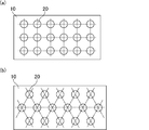
- FIG. 2A and FIG. 2B are schematic views showing an example of an array pattern of non-through holes opened on the surface of the fiber layer in the sound absorbing material of the present invention.
- FIG. 3A and FIG. 3B are cross-sectional views schematically showing an example of a non-through hole constituting the sound absorbing material of the present invention.
- FIG. 4 (a) is a perspective view schematically showing another example of the sound absorbing material of the present invention
- FIG. 4 (b) is a sectional view taken along line BB in FIG. 4 (a).
- FIG. 5 is an explanatory view schematically showing a device for measuring the normal incident sound absorption coefficient with respect to the sound absorbing material.
- the sound-absorbing material of the present invention is a sound-absorbing material comprising a fiber layer, wherein the fiber layer is formed with a plurality of non-through holes that open to the surface, and the thickness of the fiber layer is 3 mm or more.
- the non-through hole refers to a hole having a diameter of 0.5 mm or more formed in the fiber layer, the opening diameter of which is maintained on the surface of the fiber layer, and which does not penetrate both sides of the fiber layer. .
- FIG. 1 (a) is a perspective view schematically showing an example of the sound absorbing material of the present invention
- FIG. 1 (b) is a cross-sectional view taken along the line AA in FIG. 1 (a).
- the sound absorbing material 1 includes a fiber layer 10, and the fiber layer 10 is formed with a non-through hole 20 that opens to the surface.
- the thickness of the fiber layer 10 is the depth of the non-through hole 20 (in FIG. 1 (b), both Therefore, the non-through hole 20 does not penetrate through the fiber layer 10.
- the thickness of the fiber layer constituting the sound absorbing material of the present invention is preferably 3 mm or more, and more preferably 3 to 50 mm. If the thickness of the fiber layer is less than 3 mm, it is too thin to absorb sound, and it becomes difficult to ensure sufficient sound absorption performance. If the thickness of the fiber layer exceeds 50 mm, there is no problem in terms of functional performance and sound absorption as a sound absorbing material, but the sound absorbing material is used for engines, engine compartments, vehicle interiors, vehicle bodies, and exhaust pipe vehicles. In such a case, the thickness becomes a bottleneck, and it may not be possible to arrange the sound absorbing material for vehicle use.
- the fiber layer is composed of inorganic fibers.
- Inorganic fibers have high heat resistance and do not easily change shape due to temperature changes. Therefore, by constituting the fiber layer with inorganic fibers, sound is absorbed even in the voids formed with the fibers, so that sound absorption performance is easily obtained.
- the inorganic fiber is preferably made of at least one selected from the group consisting of alumina fiber, alumina-silica fiber, silica fiber, glass wool and rock wool. These inorganic fibers have high heat resistance and are difficult to change in shape. Therefore, it is suitable as an inorganic fiber forming the fiber layer.
- the inorganic fibers constituting the fiber layer are more preferably alumina-silica fibers.
- the average fiber length of the inorganic fibers is preferably from 0.1 to 150 mm, more preferably from 1 to 20 mm, and even more preferably from 2 to 15 mm. If the average fiber length of the inorganic fibers is less than 0.1 mm, the fibers are too short, so that the fibers are not easily entangled with each other, the strength of the fiber layer is difficult to obtain, and the shape retention of the fiber layer is reduced. Therefore, it can no longer serve as a sound absorbing material. If the average fiber length of the inorganic fibers exceeds 150 mm, the fiber layer is too long, making it difficult to produce a fiber layer. Furthermore, since the denseness of the fiber layer is lowered and the shear strength is also lowered, defects such as cracks are likely to occur as the sound absorbing material, and the role as the sound absorbing material cannot be achieved.
- the fiber layer constituting the sound absorbing material can be obtained by various methods, but can be produced by a needling method or a papermaking method.
- the fiber layer obtained by the needling method exhibits an entangled structure.
- the fibers need to have a certain average fiber length. Therefore, the average fiber length of the fibers used in the needling method is preferably 0.1 to 150 mm, more preferably 10 to 20 mm, and even more preferably 2 to 15 mm. If the average fiber length of the fiber is less than 0.1 mm, the fiber length of the fiber is too short, so that the interlaced fibers become insufficient, the strength of the fiber layer is difficult to obtain, and the shape retention of the fiber layer is reduced. As a result, it cannot function as a sound absorbing material.
- the winding property is lowered and the sound absorbing material is easily broken. If the average fiber length of the fiber exceeds 150 mm, the fiber length of the fiber is too long, so the number of fibers constituting the sound absorbing material is reduced, and the denseness of the fiber layer is reduced, so that problems such as cracks occur as the sound absorbing material. It becomes easy.
- the average fiber length of the fibers constituting the fiber layer obtained by the papermaking method is preferably 0.1 to 20 mm. If the average fiber length of the fibers is less than 0.1 mm, the fiber length of the fibers is too short, so that the shape retainability as the fiber layer is lowered. Further, when the fiber assembly of the fiber layer is formed, suitable entanglement between the fibers does not occur, and it becomes difficult to obtain a sufficient surface pressure.
- the fiber length of the fibers is too long, so that the entanglement of the fibers in the slurry solution in which the fibers are dispersed in water in the paper making process becomes too strong, and the fiber aggregate of the fiber layer In this case, the fibers are likely to be accumulated non-uniformly and the shear strength is also reduced, so that problems such as cracks are likely to occur as the sound absorbing material.
- the fiber length is measured by using tweezers for both the needling method and the paper making method so that the fiber is not broken from the fiber layer, and the fiber length is measured using an optical microscope.
- the average fiber length means an average length obtained by extracting 300 fibers from the fiber layer and measuring the fiber length.
- the average fiber diameter of the fibers forming the fiber layer is preferably 1 to 20 ⁇ m, more preferably 2 to 15 ⁇ m, and even more preferably 3 to 10 ⁇ m.
- the average fiber diameter of the fibers is less than 1 ⁇ m, the fiber strength is weak and the fibers are easily cut by impact or the like. For this reason, it is difficult to obtain the strength of the fiber layer, and it cannot serve as a sound absorbing material.
- the average fiber diameter of the fiber exceeds 20 ⁇ m, the fiber diameter is too large, the Young's modulus of the fiber itself is increased, the flexibility of the fiber layer is lowered, and the fiber is easily broken as a sound absorbing material.
- the fiber layer of the present invention may contain fibers such as biosoluble fibers in addition to the inorganic fibers.
- a non-through hole that opens to the surface is formed in the fiber layer.
- the depth of the non-through hole is desirably 45 to 55% of the thickness of the fiber layer.
- FIG. 2A and FIG. 2B are schematic views showing an example of an array pattern of non-through holes opened on the surface of the fiber layer in the sound absorbing material of the present invention.
- the arrangement pattern of the non-through holes opened on the surface of the fiber layer is such that the non-through holes 20 are formed at the apexes of the squares in a plane in which squares are continuously arranged vertically and horizontally as shown in FIG.
- a staggered arrangement in which the non-through holes 20 are arranged at the apexes of the triangles in a plane in which the regular triangles are arranged vertically and horizontally as shown in FIG. Good.
- a staggered arrangement is desirable. If the arrangement pattern of the non-through holes is a staggered arrangement, the adjacent non-through holes are all likely to be equally spaced, so that sound attenuation efficiency is good.
- the shape of the non-through hole is not particularly limited, and the cross-sectional shape when the fiber layer is cut in the direction perpendicular to the thickness direction is circular, elliptical, triangular, quadrangular, hexagonal, eight It may be rectangular or the like, and is preferably circular or elliptical. This is because there is no corner in these circles and ellipses, and stress concentration does not start from the corner.
- the non-through holes may all have the same shape or different shapes.
- the non-through hole has an opening area smaller than the bottom area. If the opening area of the non-through hole is smaller than the bottom area, the sound incident on the non-through hole tends to stay in the non-through hole and the sound is easily absorbed.
- a through hole with a relatively small cross-sectional area disposed on the opening surface side, and a through hole with a relatively large cross-sectional area disposed on the bottom surface side Are connected to each other (also referred to as a Helmholtz resonance structure) and a tapered columnar shape (also referred to as a tapered columnar shape), and a tapered columnar shape is desirable.
- a tapered columnar shape When the shape of the non-through hole is the tapered columnar shape, sound entering the non-through hole is easily attenuated in the non-through hole, so that sound absorption characteristics are improved.
- the angle formed by the wall surface forming the non-through hole and the bottom surface forming the non-through hole is preferably less than 90 °, and 45 ° or more. More desirably, it is less than 90 °. If the angle formed by the wall surface forming the non-through hole and the bottom surface forming the non-through hole is less than 90 °, the opening area of the non-through hole is smaller than the bottom area, and sound incident into the non-through hole is It becomes easy to stay in the non-through hole, and sound is easily absorbed.
- an opening area per one of the non-through holes is 0.1 to 15 mm 2 . If the opening area per one non-through hole is less than 0.1 mm 2 , it becomes difficult for sound to enter the non-through hole, and attenuation due to reflection of sound in the non-through hole is less likely to occur. Sound absorption performance is difficult to obtain. If the opening area per non-through hole exceeds 15 mm 2 , the sound having the frequency set as the design is reflected by the non-through hole and is not easily absorbed. As a result, it is difficult to obtain sound absorption performance.
- the opening area per non-through hole is in the range of 0.1 to 15 mm 2 , sound is reflected and absorbed easily in the non-through hole, and sound absorption performance is easily obtained. Furthermore, it is easy to obtain sound absorption performance for sound in a low frequency region of 2000 Hz or less.
- FIG. 3A and FIG. 3B are cross-sectional views schematically showing an example of a non-through hole constituting the sound absorbing material of the present invention.
- the angle ⁇ formed by the wall surface 21 a constituting the non-through hole 21 and the bottom surface 21 b constituting the non-through hole 21 is 90 °.
- the angle ⁇ formed by the wall surface 22a constituting the non-through hole 22 and the bottom surface 22b constituting the non-through hole 22 is less than 90 °.
- the opening area of the non-through hole is smaller than the bottom area. The sound that enters the lens is likely to stay in the non-through hole, and the sound is easily absorbed.
- the fiber layer is preferably formed by laminating two or more fiber layers.
- the thickness of the sound absorbing material and the depth of the non-through hole can be easily adjusted.
- Two or more fiber layers may be bonded with an adhesive such as an inorganic adhesive or an organic adhesive, but at this time, the bottom of the non-through hole is not so that the adhesive does not inhibit sound absorption. Note that no adhesive is used.
- the through hole is formed in the first fiber layer, and the through hole is formed in the second through hole.
- the sound absorbing material of the present invention can be produced by bonding the first fiber layer and the second fiber layer with an adhesive or the like.
- the thickness of the sound absorbing material and the thickness of the non-through hole can be easily adjusted by adjusting the thicknesses of the first fiber layer and the second fiber layer, respectively.
- the adhesive does not adhere to the position corresponding to the position of the through hole formed in the first fiber layer in the surface of the second fiber layer on the side in contact with the first fiber layer.
- the types of materials such as fibers constituting each fiber layer in the two or more fiber layers may be the same type or different types.
- the thickness of each fiber layer in the two or more fiber layers may be the same or different.
- the bulk density of each fiber layer in two or more fiber layers may be the same or different.
- FIG. 4 (a) is a perspective view schematically showing another example of the sound absorbing material of the present invention
- FIG. 4 (b) is a sectional view taken along line BB in FIG. 4 (a).
- the sound absorbing material 2 is composed of a fiber layer 10, and the fiber layer 10 has a non-through hole 20 that opens on the surface.
- a silica cloth layer 30 is formed on the fiber layer 10. Is formed. As shown in FIG. 4B, the silica cloth layer 30 is formed on the surface of the fiber layer 10 on the side where the non-through holes 20 are opened with a predetermined thickness t. Covering.
- the silica cloth layer is a layer made of a woven fabric containing silica fibers, and the average fiber diameter of the silica fibers constituting the silica cloth layer is preferably 5 to 20 ⁇ m.
- the thickness of the silica cloth layer is preferably 0.5 to 3 mm.
- the method of weaving silica fibers into a woven fabric is not particularly limited. Since the silica cloth layer is a woven fabric of silica fibers, it has a regular structure consisting of warps and wefts. On the other hand, since the fiber layer is a random assembly of fibers, even if the fiber layer uses silica fibers as inorganic fibers, the assembly state and physical characteristics of the fibers are clearly different from the silica cloth layer.
- the sound absorbing material of the present invention desirably has an average sound absorption coefficient of 0.6 or more in a frequency range of 800 to 2000 Hz. Sound in the frequency range of 800 to 2000 Hz is unpleasant for humans. When the average sound absorption coefficient in this frequency region is 0.6 or more, the sound in the frequency region of 800 to 2000 Hz is absorbed, and it is possible to make the person in the vehicle less likely to feel uncomfortable. It can be said that it has sound absorption performance.
- the shape of the sound absorbing material of the present invention is not particularly limited as long as it is a shape that fits in a place where the sound absorbing material is disposed.
- the method for producing a sound absorbing material of the present invention described below includes (1) a fiber layer manufacturing step and (2) a non-through hole forming step.
- Fiber layer preparation process In this process, a fiber layer is prepared.
- the method for preparing the fiber layer is not particularly limited. Below, the method of preparing the fiber layer by the needle method (it is also called the needling method and the needle punching method) which is the example, and a papermaking method is demonstrated.
- an inorganic fiber precursor is prepared by spinning a spinning mixture using a basic aluminum chloride aqueous solution and silica sol as raw materials by a blowing method.
- the inorganic fiber precursor is compressed to produce a continuous sheet-like material having a predetermined size, subjected to a needle punching process, and then subjected to a firing process to thereby form an inorganic fiber having an average fiber diameter of 3 to 10 ⁇ m.
- the layer production is complete.
- a needle punching process may be performed before the baking process.
- an inorganic fiber such as alumina fiber and silica fiber, an inorganic binder, an organic binder, and water are mixed so that the content of the inorganic fiber in the raw material liquid becomes a predetermined value, and a stirrer
- the mixture is prepared by stirring at.
- the mixed solution may contain a colloidal solution made of a polymer compound or a resin as necessary.
- Non-through hole forming step In this step, a non-through hole is formed in the fiber layer produced in the above (1) fiber layer producing step.
- the method of forming the non-through hole is not particularly limited, and examples thereof include a method of punching a part of the fiber layer so as not to penetrate the fiber layer using a cutter, a laser, a drill, or the like.
- a method for producing the sound absorbing material of the present invention in addition to the method described above, a method of laminating a plurality of fiber layers may be mentioned.
- a plurality of fiber layers are prepared in the (1) fiber layer preparation step, and the through hole is formed in one of the plurality of prepared fiber layers without performing the (2) non-through hole forming step.
- a tapered columnar through hole may be formed as the through hole.
- a sound-absorbing material having a non-through hole whose opening area is smaller than the bottom area is obtained by adhering a side having a large opening area of a fiber layer having a tapered columnar through hole and a fiber layer not forming a through hole. Obtainable. Further, in such a method, by adjusting the thickness of the fiber layer to be produced in the above (1) fiber layer production step, the thickness of the sound absorbing material to be obtained and the depth of the non-through hole to be formed can be reduced. Can be adjusted.
- the use of the sound-absorbing material of the present invention is not particularly limited, but it is preferably used for a vehicle. Specifically, it may be used for any of an engine, an engine room, a vehicle interior, a vehicle body, and an exhaust pipe. desirable. Since the sound absorbing material of the present invention has good sound absorbing performance in the frequency range of 500 to 2000 Hz, it can be suitably used for the above applications.
- the sound absorbing material when used for an engine, an engine room, a vehicle interior, a vehicle body, and an exhaust pipe, it may be arranged on a curved surface. In such a case, it is necessary to curve the sound absorbing material. In this case, stress is generated in the sound absorbing material, and cracks and cracks are likely to occur. Therefore, a sound absorbing material having a shape that matches the shape of the curved surface may be prepared in advance and arranged on the curved surface. Further, by preparing a large number of small sound absorbing materials and arranging the large number of sound absorbing materials on a curved surface, the stress generated in each sound absorbing material may be relieved and cracking or cracking of the sound absorbing material may be prevented. .
- the vehicle component of the present invention will be described.
- the vehicle component of the present invention is the side of the fiber layer where the non-through hole is opened on the surface of a member constituting the engine, engine room component, vehicle interior, vehicle body or exhaust pipe. It is characterized by being arranged with its surface facing. Since the sound-absorbing material of the present invention has an excellent sound-absorbing performance with respect to sounds in the frequency range of 500 to 2000 Hz, the vehicle component of the present invention using the sound-absorbing material transmits sound to people in the vehicle. This can be hindered, and the quiet performance of the vehicle can be improved.
- the composition ratio in the inorganic fiber after firing is alumina (
- a silica sol was blended so that Al 2 O 3 ): silica (Si
- the spun inorganic fiber precursors were laminated and subjected to needling treatment to produce two sheets.
- Each obtained sheet-like product is continuously fired at a maximum temperature of 1250 ° C., and is made of inorganic fibers having a length of 600 mm, a width of 200 mm, and a thickness of 7 mm and containing alumina and silica in a ratio of 72:28 (weight ratio).
- Two fiber layers were obtained.
- the resulting fiber layer had a bulk density of 0.15 g / cm 3 and a basis weight of 1050 g / m 2 .
- a fiber layer is formed on one of the obtained fiber layers using a punching machine so that the shape is a circle having a diameter of 3 mm, the interval is 8 mm, and the arrangement pattern is a staggered arrangement.
- the hole which penetrates was formed.
- the sound absorbing material according to Example 1 was manufactured by laminating the fiber layer in which the holes were formed as the first fiber layer and the fiber layer in which the holes were not formed as the second fiber layer. A hole formed in the surface of the first fiber layer becomes a non-through hole. In the sound absorbing material according to Example 1, the depth of the non-through hole with respect to the thickness of the fiber layer was 50%.
- Example 2 The thickness of the fiber layer produced in the (1) fiber layer production process was changed to 6.3 mm and 7.7 mm, respectively, without changing the bulk density. Subsequently, in the above (2) hole forming step, holes were formed in the fiber layer having a thickness of 6.3 mm in the same arrangement pattern as in Example 1. The fiber layer (thickness 6.3 mm) in which the holes were formed was used as the first fiber layer, and the fiber layer (thickness 7.7 mm) in which the holes were not formed was laminated as the second fiber layer, thereby providing Example 2. The sound-absorbing material according to was produced. In the sound absorbing material according to Example 2, the depth of the non-through hole with respect to the thickness of the fiber layer was 45%.
- Example 3 A fiber in which holes are formed in a fiber layer having a thickness of 7.7 mm in the (2) hole forming step, the fiber layer in which the holes are formed (thickness: 7.7 mm) is used as the first fiber layer, and the holes are not formed.
- a sound-absorbing material according to Example 3 was produced in the same procedure as in Example 2, except that a layer (thickness: 6.3 mm) was laminated as the second fiber layer. In the sound absorbing material according to Example 3, the depth of the non-through hole with respect to the thickness of the fiber layer was 55%.
- Example 4 The thickness of the fiber layer produced in the above (1) fiber layer production step was changed to 3 mm and 11 mm, respectively, without changing the bulk density. Subsequently, in the (2) hole forming step, holes similar to those in Example 1 were formed in the fiber layer having a thickness of 3 mm.
- a sound absorbing material according to Example 4 is formed by laminating a fiber layer (thickness 3 mm) with holes as a first fiber layer and a fiber layer (thickness 11 mm) with no holes as a second fiber layer. Got. In the sound absorbing material according to Example 4, the depth of the non-through hole with respect to the thickness of the fiber layer was 21%.
- Example 5 A sound-absorbing material according to Example 5 was obtained by bonding a silica cloth having a thickness of 0.6 mm to the surface of the sound-absorbing material obtained in Example 1 (the surface on the side where the non-through holes are opened) with an adhesive. .
- Comparative Example 1 The sound absorbing material according to Comparative Example 1 was obtained by laminating two fiber layers in which holes were not formed without performing the (2) hole forming step. In the sound absorbing material according to Comparative Example 1, neither through-holes nor non-through holes were formed (for the sake of convenience, the depth of the non-through holes with respect to the thickness of the fiber layer is also expressed as 0%).
- the sound absorption coefficient was measured by a normal incidence sound absorption coefficient test. The measurement was performed according to JIS A 1405-2: 2007 “Measurement of sound absorption coefficient and impedance by an acoustic tube—Part 2: Transfer function method”.
- the sound absorbing materials according to Examples 1 to 5 and Comparative Examples 1 and 2 were cut into a circular shape with a diameter of 29 mm, and a normal incident sound absorption coefficient measuring device (manufactured by Nittobo Acoustic Engineering Co., Ltd.) : Measurement was performed in a frequency range of 500 to 6400 Hz after being placed on an acoustic tube in WinZac MTX).
- FIG. 5 is an explanatory view schematically showing a device for measuring the normal incident sound absorption coefficient with respect to the sound absorbing material.
- a sample 82 is disposed at the tip of the acoustic tube 81, and noise is generated from the speaker 84 by a signal from the noise generator 83 to generate a sound field inside the acoustic tube 81.
- the sound pressure signals of the two 1/4 inch microphones 85 and 86 are subjected to FFT (Fast Fourier Transform) analysis by the FFT analyzer 87 to calculate the normal incident sound absorption coefficient.
- FFT Fast Fourier Transform
- the non-through holes are not formed in the sound-absorbing materials according to Comparative Examples 1 and 2, it is not considered whether the non-through holes are open surfaces, and any surface of the fiber layer is positioned on the speaker 84 side.
- a sound-absorbing material was placed in From the obtained sound absorption coefficient chart, the average sound absorption coefficient in the frequency range of 500 to 2000 Hz was measured. Those having an average sound absorption coefficient of 0.46 or more were evaluated as good ( ⁇ ) for sound absorption performance, and those having an average sound absorption ratio of less than 0.46 were evaluated as being insufficient ( ⁇ ). Further, the average sound absorption coefficient in the frequency region of 800 to 2000 Hz was obtained. The results are shown in Table 1.
- the sound absorbing materials according to Examples 1 to 5 all had good sound absorbing performance in the frequency range of 500 to 2000 Hz. Further, in Examples 1 to 3 and Example 5 in which the ratio of the depth of the non-through holes to the thickness of the fiber layer is 45 to 55%, the average sound absorption coefficient in the frequency region of 800 to 2000 Hz is 0.6 or more. there were. Since the sound having a frequency of 800 to 2000 Hz becomes unpleasant for a person, the sound absorbing material according to Examples 1 to 3 and 5 having an average sound absorption coefficient in the frequency region of 0.6 or more is suitable for a person in the vehicle. It is a particularly excellent sound absorbing material that is less likely to cause discomfort.
- the sound absorbing material according to Example 5 in which the silica cloth layer was formed on the fiber layer was particularly excellent in the average sound absorption coefficient in the frequency range of 800 to 2000 Hz.
- the sound absorbing materials according to Comparative Examples 1 and 2 in which the non-through holes were not formed in the fiber layer had insufficient sound absorbing performance in the frequency range of 500 to 2000 Hz.
Landscapes
- Engineering & Computer Science (AREA)
- Physics & Mathematics (AREA)
- Acoustics & Sound (AREA)
- Textile Engineering (AREA)
- Mechanical Engineering (AREA)
- Multimedia (AREA)
- Vehicle Interior And Exterior Ornaments, Soundproofing, And Insulation (AREA)
- Soundproofing, Sound Blocking, And Sound Damping (AREA)
Abstract
Description
そのため、エンジン、エンジンルーム内、車両内装、車両ボディ、排気管周辺部等での遮音・吸音による防音対策が行われている。
なお、シリカクロス層は、繊維層の非貫通孔が開口する面上に形成される。
繊維層上にさらにシリカクロス層が形成されていると、非貫通孔上に形成されたシリカクロス層の膜振動と通気抵抗の効果により、吸音率をさらに向上させることができる。
吸音材が音を受けると、その音は、繊維層の表面に開口する非貫通孔に入射され、非貫通孔で反射し、減衰するとともに繊維層内に吸収されることで音が吸音されることになる。
なお本発明では、繊維層のうち非貫通孔が表面に開口する面が音を受ける面となる。
繊維層の厚さが3mm未満であると、音を吸収するためには薄すぎ、充分な吸音性能を確保できない。
また、本発明の吸音材における繊維層の厚さは、3~50mmであることがより望ましい。繊維層の厚さが50mmを超えると、エンジン、エンジンルーム内、車両内装、車両ボディ、排気管等の車両用途に吸音材を用いたとき、厚みがネックとなり、車両用途で吸音材を配置することができなくなることがある。
なお、本発明の吸音材において、繊維層の厚さは、非貫通孔が形成されていない部分の厚さとする。このとき、繊維層の厚さは、ノギスを用いて測定した任意の3点の平均値とする。
非貫通孔の深さが繊維層の厚さの45~55%であると、500~2000Hzの周波数領域における吸音性能を向上させることができ、さらには、800~2000Hzの周波数領域における平均吸音率を0.6以上とすることができる。
なお、500~2000Hzの周波数領域における吸音性能が良好であるとは、500~2000Hzの周波数領域における平均吸音率が0.46以上であることを指す。
本発明において「吸音率」とは、JIS A 1405-2:2007「音響管による吸音率及びインピーダンスの測定-第2部:伝達関数法」に準じて測定された吸音率を意味する。また、500~2000Hzの周波数領域における平均吸音率は、500~2000Hzの周波数領域を1/3オクターブバンドに区切った、500Hz、630Hz、800Hz、1000Hz、1250Hz、1600Hz、2000Hzにおける吸音率の平均値で算出される。
非貫通孔において開口面積が底面積よりも小さいと、非貫通孔内に入射した音が非貫通孔内に留まりやすくなり、音が吸収されやすくなる。
非貫通孔を構成する壁面と底面とのなす角が上記範囲であると、非貫通孔内に入射した音が非貫通孔内に特に留まりやすくなり、音がより吸収されやすくなる。
2層以上の繊維層を用いることにより、吸音材の厚さを容易に調節することができる。また、非貫通孔の深さの調節も容易となる。
なお、繊維層が2層以上の繊維層を積層することにより構成されている場合、繊維層の厚さは各繊維層の厚さの合計とする。
無機繊維は耐熱性が高く、温度変化によって形状変化しにくい。そのため、繊維層として無機繊維を用いることで、繊維で形成された空隙内でも音の吸音がされるので吸音性能が得られやすい。
これらの無機繊維は耐熱性が高く、温度変化によって形状変化しにくい。従って、繊維層を形成する無機繊維として好適である。
非貫通孔の1つあたりの開口面積が、0.1mm2未満であると、音が非貫通孔に入りにくくなって、非貫通孔内で音が反射することによる減衰が起こりにくくなるため、吸音性能が得られにくくなる。
非貫通孔の1つあたりの開口面積が、15mm2を超えると、設計として設定している周波数の音が非貫通孔で反射し、吸収されにくくなる。その結果、吸音性能が得られにくくなる。
非貫通孔の1つあたりの開口面積が0.1~15mm2の範囲であると、非貫通孔内で音が反射し、吸収しやすくなり、吸音性能が得られやすくなる。さらに2000Hz以下の低周波数領域の音に対する吸音性能が得られやすくなる。
800~2000Hzの周波数領域の音は、人にとって不快な音である。この周波数領域における平均吸音率が0.6以上であると、人にとって不快な音が吸収され、車両内の人が不快さを感じにくくすることができるので、吸音材としての優れた吸音性能を有しているといえる。
800~2000Hzの周波数領域における平均吸音率は、800Hz~2000Hzを1/3オクターブバンドに区切った、800Hz、1000Hz、1250Hz、1600Hz、2000Hzにおける吸音率を測定し、平均値を求めればよい。
本発明の吸音材は、500~2000Hzの周波数領域における吸音性能が良好であるため、上記用途に好適に用いることができる。
本発明の吸音材は500~2000Hzの周波数領域の音に対して優れた吸音性能を有しているから、これを用いた本発明の車両部品は、車両内の人への音の伝達を妨げることができ、車両の静粛性能を向上させることができる。
以下、本発明の吸音材について詳述する。
なお、非貫通孔とは、繊維層に形成された直径0.5mm以上の孔のうち、繊維層表面の開口径が維持されており、かつ、繊維層の両面を貫通していないものを指す。
図1(a)は、本発明の吸音材の一例を模式的に示す斜視図であり、図1(b)は図1(a)におけるA-A線断面図である。
図1(a)に示すように、吸音材1は、繊維層10からなり、繊維層10には、表面に開口する非貫通孔20が形成されている。図1(b)に示すように、繊維層10の厚さ(図1(b)中、両矢印Tで示される長さ)は非貫通孔20の深さ(図1(b)中、両矢印dで示される長さ)よりも大きいため、非貫通孔20は繊維層10を貫通していない。
繊維層の厚さが3mm未満であると、音を吸収するためには薄すぎ、充分な吸音性能を確保しにくくなる。
なお、繊維層の厚さが50mmを超えると、吸音材としての機能性能、吸音性としては問題ないが、エンジン、エンジンルーム内、車両内装、車両ボディ、排気管の車両用途に吸音材を用いたとき、厚みがネックとなり、車両用途で吸音材を配置することができなくなることがある。
無機繊維は耐熱性が高く、温度変化によって形状変化しにくい。そのため、繊維層を無機繊維で構成することで、繊維で形成された空隙内でも音の吸音がされるので吸音性能が得られやすい。
これらの無機繊維は耐熱性が高く、形状変化しにくい。従って、繊維層を形成する無機繊維として好適である。
繊維層を構成する無機繊維は、アルミナ-シリカ繊維であることがより望ましい。
無機繊維の平均繊維長が0.1mm未満であると、繊維が短すぎるため、繊維層において繊維同士が絡みあいにくく、繊維層の強度が得られにくくなり、繊維層の形状保持性が低下してしまい、吸音材としての役目を果たせなくなる。
無機繊維の平均繊維長が150mmを超えると、繊維が長すぎるために繊維層の作製が難しくなる。さらに、繊維層の緻密性が低下し、せん断強度も低下するので、吸音材として割れ等の不具合が発生しやすくなり、吸音材としての役目を果たせなくなる。
繊維の平均繊維長が0.1mm未満であると、繊維の繊維長が短すぎるため、繊維同士の交絡が不充分となり、繊維層の強度が得られにくくなり、繊維層の形状保持性が低下してしまい、吸音材としての役目を果たせなくなる。さらに、吸音材を排気管等の管状物へ巻き付けると、巻き付け性が低下し、吸音材が割れやすくなる。
繊維の平均繊維長が150mmを超えると、繊維の繊維長が長すぎるため、吸音材を構成する繊維本数が減少し、繊維層の緻密性が低下するので吸音材として割れ等の不具合が発生しやすくなる。
繊維の平均繊維長が0.1mm未満であると、繊維の繊維長が短すぎるため、繊維層としての形状保持性が低下してしまう。さらに、繊維層の繊維集合体にしたときに繊維同士に好適な絡み合いが起こらず、充分な面圧を得ることが困難になる。
繊維の平均繊維長が20mmを超えると、繊維の繊維長が長すぎるため、抄造工程で水に繊維を分散したスラリー溶液中の繊維同士の絡み合いが強くなりすぎて、繊維層の繊維集合体としたときに繊維が不均一に集積しやすくなり、せん断強度も低下するので、吸音材として割れ等の不具合が発生しやすくなる。
本明細書において、平均繊維長とは、繊維層から繊維300本を抜き取り、繊維長を計測した平均長さを意味する。繊維層から繊維を破断せずに抜き取れない場合、繊維層を脱脂処理して、脱脂済み繊維層を水の中へ投入し、繊維同士の絡みをほぐしながら繊維が破断しないように採取するとよい。
繊維の平均繊維径が1μm未満であると、繊維強度が弱く、衝撃等により繊維が裁断されやすくなる。そのため、繊維層の強度が得られにくくなり、吸音材としての役目を果たせなくなる。
繊維の平均繊維径が20μmを超えると、繊維径が太すぎて繊維自体のヤング率が高くなり繊維層の柔軟性が低くなり吸音材として破壊されやすくなる。
非貫通孔の深さは、繊維層の厚さの45~55%であることが望ましい。
図2(a)及び図2(b)は、本発明の吸音材において繊維層の表面に開口する非貫通孔の配列パターンの一例を示す模式図である。
本発明の吸音材において繊維層の表面に開口する非貫通孔の配列パターンは、図2(a)に示すような、正方形を縦横に連続して配置した平面において正方形の頂点に非貫通孔20を配置する正方配列であってもよく、図2(b)に示すような、正三角形を縦横に連続して配置した平面において三角形の頂点に非貫通孔20を配置する千鳥配列であってもよい。
これらの中では、千鳥配列であることが望ましい。非貫通孔の配列パターンが千鳥配列であると、隣接する非貫通孔が全て等間隔となりやすいため、音の減衰効率がよい。
非貫通孔の形状は、全て同じ形状であってもよく、異なる形状であってもよい。
非貫通孔の開口面積が底面積よりも小さいと、非貫通孔内に入射した音が非貫通孔内に留まりやすくなり、音が吸収されやすくなる。
非貫通孔の形状が上記テーパー柱状であると、非貫通孔内に入った音が非貫通孔内で減衰しやすくなるため、吸音特性が向上する。
非貫通孔を構成する壁面と非貫通孔を構成する底面とのなす角が90°未満であると、非貫通孔の開口面積が底面積よりも小さくなり、非貫通孔内に入射した音が非貫通孔内に留まりやすくなり、音が吸収されやすくなる。
非貫通孔の1つあたりの開口面積が、0.1mm2未満であると、音が非貫通孔に入りにくくなって、非貫通孔内で音が反射することによる減衰が起こりにくくなるため、吸音性能が得られにくくなる。
非貫通孔の1つあたりの開口面積が、15mm2を超えると、設計として設定している周波数の音が非貫通孔で反射し、吸収されにくくなる。その結果、吸音性能が得られにくくなる。
非貫通孔の1つあたりの開口面積が0.1~15mm2の範囲であると、非貫通孔内で音が反射し、吸収しやすくなり、吸音性能が得られやすくなる。さらに2000Hz以下の低周波数領域の音に対する吸音性能が得られやすくなる。
図3(a)及び図3(b)は、本発明の吸音材を構成する非貫通孔の一例を模式的に示す断面図である。
図3(a)に示す非貫通孔21は、非貫通孔21を構成する壁面21aと非貫通孔21を構成する底面21bとのなす角αが90°となっている。一方、図3(b)に示す非貫通孔22は、非貫通孔22を構成する壁面22aと非貫通孔22を構成する底面22bとのなす角βが90°未満となっている。図3(b)に示すように、非貫通孔を構成する壁面と底面とのなす角が90°未満であると、非貫通孔の開口面積が底面積よりも小さくなるため、非貫通孔内に入射した音が非貫通孔内に留まりやすくなり、音が吸収されやすくなる。
2層以上の繊維層を積層することによって繊維層を構成することで、吸音材の厚さ及び非貫通孔の深さを容易に調節することができる。2層以上の繊維層は、無機接着剤や有機接着剤等の接着剤により接着されていてもよいが、この時、接着剤が音の吸収を阻害しないように、非貫通孔の底部分には接着剤を用いないことに留意する必要がある。
例えば、非貫通孔の深さを調整する場合、音源に近い側から第1繊維層、第2繊維層とすると、第1繊維層に貫通孔を形成し、第2貫通孔に貫通孔を形成せず、第1繊維層と第2繊維層とを接着剤等により接着することにより本発明の吸音材を製造することができる。この時、第1繊維層及び第2繊維層の厚さをそれぞれ調整することにより、吸音材の厚さ及び非貫通孔の厚さを容易に調節することができる。なお、第1繊維層と接触する側の第2繊維層の表面のうち、第1繊維層に形成された貫通孔の位置に対応する位置に接着剤が付着しないよう留意する。
2層以上の繊維層における各繊維層の厚さは、同じ厚さであっても、異なる厚さであってもよい。2層以上の繊維層における各繊維層の嵩密度は、同じ嵩密度であっても、異なる嵩密度であってもよい。
本発明の吸音材の他の態様について、図4を用いて説明する。
図4(a)は、本発明の吸音材の別の一例を模式的に示す斜視図であり、図4(b)は、図4(a)におけるB-B線断面図である。
図4(a)に示すように、吸音材2は、繊維層10からなり、繊維層10には表面に開口する非貫通孔20が形成されており、繊維層10上にはシリカクロス層30が形成されている。
なお、図4(b)に示すように、シリカクロス層30は、繊維層10のうち表面に非貫通孔20が開口する側の面上に所定の厚さtで形成され、非貫通孔20を覆っている。
またシリカクロス層の厚さは、0.5~3mmであることが望ましい。
シリカ繊維を織って織物とする方法は特に限定されない。
なお、シリカクロス層はシリカ繊維の織物であるから、縦糸と横糸からなる規則的な構造を有している。一方、繊維層は繊維のランダム集合体であるから、たとえ無機繊維としてシリカ繊維を使用した繊維層であっても、繊維の集合状態及び物理的特性がシリカクロス層とは明確に異なる。
800~2000Hzの周波数領域の音は、人にとって不快な音である。この周波数領域における平均吸音率が0.6以上であると、800~2000Hzの周波数領域の音が吸収され、車両内の人に不快さを感じにくくすることができるので、吸音材としての優れた吸音性能を有しているといえる。
以下に説明する本発明の吸音材の製造方法は、(1)繊維層作製工程、(2)非貫通孔形成工程を含む。
本工程では、繊維層を準備する。繊維層を準備する方法は特に限定されない。以下に、その一例であるニードル法(ニードリング法、ニードルパンチング法ともいう)及び抄造法による繊維層を準備する方法を説明する。
本工程では、上記(1)繊維層作製工程にて作製した繊維層に非貫通孔を形成する。
非貫通孔を形成する方法は、特に限定されないが、例えば、カッター、レーザー、ドリル等を用いて繊維層を貫通しないように、繊維層の一部を刳り貫く方法が挙げられる。
この場合、上記(1)繊維層作製工程において複数枚の繊維層を作製しておき、上記(2)非貫通孔形成工程を行わず、複数枚作製した繊維層のうちの1枚に貫通孔を形成し、貫通孔を形成していない繊維層と接着する方法が挙げられる。この時、貫通孔としてテーパー柱状の貫通孔を形成してもよい。テーパー柱状の貫通孔が形成された繊維層の開口面積が大きい側と貫通孔を形成していない繊維層とを接着することにより、開口面積が底面積よりも小さい非貫通孔を有する吸音材を得ることができる。
また、このような方法であると、上記(1)繊維層作製工程において作製する繊維層の厚さを調整することにより、得られる吸音材の厚さ及び形成される非貫通孔の深さを調整することができる。
本発明の吸音材は、500~2000Hzの周波数領域における吸音性能が良好であるため、上記用途に好適に用いることができる。
本発明の車両部品は、本発明の吸音材を、エンジン、エンジンルーム用部品、車両内装、車両ボディ又は排気管を構成する部材の表面に、上記繊維層のうち上記非貫通孔が開口する側の表面を向けて配置してなることを特徴とする。
本発明の吸音材は、500~2000Hzの周波数領域の音に対して優れた吸音性能を有しているから、これを用いた本発明の車両部品は、車両内の人への音の伝達を妨げることができ、車両の静粛性能を向上させることができる。
以下に本発明をより具体的に説明する実施例を示すが、本発明はこれらの実施例に限定されるものではない。
(1)繊維層作製工程
(繊維層の作製)
ニードリング法によって繊維層を作製した。
Al含有量が70g/Lであり、Al:Cl=1:1.8(原子比)となるように調製した塩基性塩化アルミニウム水溶液に対して、焼成後の無機繊維における組成比が、アルミナ(Al2O3):シリカ(SiO2)=72:28(重量比)となるようにシリカゾルを配合し、さらに、有機重合体(ポリビニルアルコール)を適量添加して混合液を調製した。
得られた混合液を濃縮して紡糸用混合物とし、この紡糸用混合物をブローイング法により紡糸して無機繊維前駆体を作製した。
紡糸した無機繊維前駆体を積層して、ニードリング処理し、シート状物を2枚作製した。
得られた各シート状物を、最高温度1250℃で連続して焼成し、長さ600mm、幅200mm、厚さ7mmの、アルミナとシリカとを72:28(重量比)で含む無機繊維からなる繊維層を2枚得た。
得られた繊維層の嵩密度は0.15g/cm3であり、坪量は1050g/m2であった。
次に、形状が直径3mmの円形であり、間隔が8mmとなり、配列パターンが千鳥配列になるように、パンチングマシーンを用いて、得られた繊維層の1枚に繊維層を貫通する孔を形成した。
孔が形成された繊維層を第1繊維層とし、孔を形成しなかった繊維層を第2繊維層として積層することによって、実施例1に係る吸音材を作製した。第1繊維層の表面に形成された孔が非貫通孔となる。
実施例1に係る吸音材における、繊維層の厚さに対する非貫通孔の深さは50%であった。
上記(1)繊維層作製工程において作製する繊維層を、嵩密度を変更せずに、厚さをそれぞれ6.3mm及び7.7mmに変更した。続いて上記(2)孔形成工程において、厚さ6.3mmの繊維層に実施例1と同様の配列パターンで孔を形成した。孔が形成された繊維層(厚さ6.3mm)を第1繊維層とし、孔を形成しなかった繊維層(厚さ7.7mm)を第2繊維層として積層することで、実施例2に係る吸音材を作製した。
実施例2に係る吸音材における、繊維層の厚さに対する非貫通孔の深さは45%であった。
上記(2)孔形成工程において厚さ7.7mmの繊維層に孔を形成し、孔が形成された繊維層(厚さ7.7mm)を第1繊維層とし、孔を形成しなかった繊維層(厚さ6.3mm)を第2繊維層として積層したほかは、実施例2と同様の手順で実施例3に係る吸音材を作製した。
実施例3に係る吸音材における、繊維層の厚さに対する非貫通孔の深さは55%であった。
上記(1)繊維層作製工程において作製する繊維層を、嵩密度を変更せずに、厚さをそれぞれ3mm及び11mmに変更した。続いて上記(2)孔形成工程において、厚さ3mmの繊維層に実施例1と同様の孔を形成した。孔が形成された繊維層(厚さ3mm)を第1繊維層とし、孔を形成しなかった繊維層(厚さ11mm)を第2繊維層として積層することで、実施例4に係る吸音材を得た。
実施例4に係る吸音材における、繊維層の厚さに対する非貫通孔の深さは21%であった。
実施例1で得られた吸音材の表面(非貫通孔が開口する側の表面)に厚さ0.6mmのシリカクロスを接着剤で接合することで、実施例5に係る吸音材を得た。
上記(2)孔形成工程を行わずに、孔の形成されていない繊維層を2枚積層することにより、比較例1に係る吸音材を得た。
比較例1に係る吸音材には貫通孔及び非貫通孔は形成されていなかった(便宜上、繊維層の厚さに対する非貫通孔の深さが0%であるとも表現する)。
上記(2)孔形成工程において2枚の繊維層の両方に孔を形成し、第1の繊維層に形成された孔の位置と第2の繊維層に形成された孔の位置とが一致するように、第1の繊維層と第2の繊維層とを接合したほかは、実施例1と同様の手順により、比較例2に係る吸音材を得た。
比較例2に係る吸音材には貫通孔が形成されており、非貫通孔は形成されていなかった(便宜上、繊維層の厚さに対する非貫通孔の深さが100%であるとも表現する)。
吸音率は、垂直入射吸音率試験により行った。測定はJIS A 1405-2:2007「音響管による吸音率及びインピーダンスの測定-第2部:伝達関数法」に準じて行った。
吸音率を測定する際には、実施例1~5及び比較例1~2に係る吸音材を直径29mmの円形となるようにカットし、垂直入射吸音率の測定装置(日東紡音響エンジニアリング製 型番:WinZac MTX)における音響管に配置した後、周波数500~6400Hzの範囲で測定を行った。
この測定装置80では、音響管81の先端にサンプル82が配置されており、ノイズ発生器83からの信号によりスピーカー84からノイズを発生させ、音響管81の内部に音場を生成させる。そして、2本の1/4インチマイクロホン85、86の音圧信号をFFT分析器87によりFFT(高速フーリエ変換)分析し、垂直入射吸音率を算出する。
なお、この測定では、実施例1~5に係る吸音材を、形成された非貫通孔の開口する面がスピーカー84側に位置するように、各吸音材を配置した。
比較例1及び2に係る吸音材には非貫通孔が形成されていないため、非貫通孔が開口する面かどうかを考慮せず、繊維層のいずれかの面がスピーカー84側に位置するように吸音材を配置した。
得られた吸音率チャートから、500~2000Hzの周波数領域における平均吸音率を測定した。平均吸音率が0.46以上のものを吸音性能が良好(○)と評価し、0.46未満のものを吸音性能が不充分(×)と評価した。また、800~2000Hzの周波数領域における平均吸音率を求めた。結果を表1に示す。

800~2000Hzの周波数の音は、人にとって不快な音となるので、この周波数領域の平均吸音率が0.6以上である実施例1~3及び5に係る吸音材は、車両内の人に不快感を与えにくい特に優れた吸音材である。
また、繊維層上にシリカクロス層が形成された実施例5に係る吸音材は、800~2000Hzの周波数領域における平均吸音率に特に優れていた。
一方、繊維層に非貫通孔が形成されていない比較例1及び2に係る吸音材は、500~2000Hzの周波数領域における吸音性能が不充分だった。
10 繊維層
20、21、22 非貫通孔
21a、22a 壁面
21b、22b 底面
30 シリカクロス層
80 測定装置
81 音響管
82 サンプル
83 ノイズ発生器
84 スピーカー
85、86 マイクロホン
87 FFT分析器
Claims (13)
- 繊維層からなる吸音材であって、
前記繊維層には、表面に開口する複数の非貫通孔が形成され、
前記繊維層の厚さは3mm以上であることを特徴とする吸音材。 - 繊維層からなる吸音材であって、
前記繊維層には、表面に開口する複数の非貫通孔が形成され、
前記繊維層の厚さは3mm以上であり、
前記繊維層上に、さらにシリカクロス層が形成されていることを特徴とする吸音材。 - 前記繊維層の厚さは3~50mmである請求項1又は2に記載の吸音材。
- 前記非貫通孔の深さは、前記繊維層の厚さの45~55%である請求項1~3のいずれかに記載の吸音材。
- 前記非貫通孔は、開口面積が底面積よりも小さい請求項1~4のいずれかに記載の吸音材。
- 前記非貫通孔を構成する壁面と前記非貫通孔を構成する底面とのなす角は、45°以上90°未満である請求項5に記載の吸音材。
- 前記繊維層は、2層以上の繊維層を積層することにより構成されている請求項1~6のいずれかに記載の吸音材。
- 前記繊維層は、無機繊維で構成されている請求項1~7のいずれかに記載の吸音材。
- 前記無機繊維は、アルミナ繊維、アルミナ-シリカ繊維、シリカ繊維、グラスウール及びロックウールからなる群から選択される少なくとも1種からなる請求項8に記載の吸音材。
- 前記非貫通孔の1つあたりの開口面積は、0.1~15mm2である請求項1~9のいずれかに記載の吸音材。
- 800~2000Hzの周波数領域における平均吸音率が0.6以上である請求項1~10のいずれかに記載の吸音材。
- 前記吸音材は、エンジン、エンジンルーム内、車両内装、車両ボディ及び排気管からなる少なくとも1種の部分に用いられる請求項1~11のいずれかに記載の吸音材。
- 請求項1~11のいずれかに記載の吸音材を、エンジン、エンジンルーム用部品、車両内装、車両ボディ又は排気管を構成する部材の表面に、前記繊維層のうち前記非貫通孔が開口する側の表面を向けて配置してなることを特徴とする車両部品。
Priority Applications (3)
| Application Number | Priority Date | Filing Date | Title |
|---|---|---|---|
| EP18771453.0A EP3605524A4 (en) | 2017-03-24 | 2018-03-22 | ISOPHONIC MATERIAL AND VEHICLE COMPONENT |
| JP2019506981A JPWO2018174180A1 (ja) | 2017-03-24 | 2018-03-22 | 吸音材及び車両部品 |
| CN201880019423.4A CN110431620A (zh) | 2017-03-24 | 2018-03-22 | 吸音材料和车辆部件 |
Applications Claiming Priority (4)
| Application Number | Priority Date | Filing Date | Title |
|---|---|---|---|
| JP2017059509 | 2017-03-24 | ||
| JP2017-059509 | 2017-03-24 | ||
| JP2017237145 | 2017-12-11 | ||
| JP2017-237145 | 2017-12-11 |
Publications (1)
| Publication Number | Publication Date |
|---|---|
| WO2018174180A1 true WO2018174180A1 (ja) | 2018-09-27 |
Family
ID=63584466
Family Applications (1)
| Application Number | Title | Priority Date | Filing Date |
|---|---|---|---|
| PCT/JP2018/011470 Ceased WO2018174180A1 (ja) | 2017-03-24 | 2018-03-22 | 吸音材及び車両部品 |
Country Status (4)
| Country | Link |
|---|---|
| EP (1) | EP3605524A4 (ja) |
| JP (1) | JPWO2018174180A1 (ja) |
| CN (1) | CN110431620A (ja) |
| WO (1) | WO2018174180A1 (ja) |
Cited By (2)
| Publication number | Priority date | Publication date | Assignee | Title |
|---|---|---|---|---|
| WO2020217862A1 (ja) * | 2019-04-26 | 2020-10-29 | ニチアス株式会社 | 排気管用減音構造体 |
| JP2021146877A (ja) * | 2020-03-19 | 2021-09-27 | 河西工業株式会社 | 自動車用遮音パネル |
Citations (4)
| Publication number | Priority date | Publication date | Assignee | Title |
|---|---|---|---|---|
| JP3057416U (ja) * | 1998-07-07 | 1999-06-02 | 吉蔵 松本 | 低周波数音域用吸音板 |
| JP2000034938A (ja) | 1998-07-17 | 2000-02-02 | Mitsubishi Motors Corp | 吸音装置 |
| JP2003135249A (ja) * | 2001-11-05 | 2003-05-13 | Suzuko Seisakusho:Kk | インシュレーター |
| JP2003266572A (ja) * | 2002-03-20 | 2003-09-24 | Nichias Corp | 防音断熱材およびその製造方法 |
Family Cites Families (9)
| Publication number | Priority date | Publication date | Assignee | Title |
|---|---|---|---|---|
| GB2207633B (en) * | 1987-07-29 | 1991-07-31 | Ronald Powell | Acoustic barrier material |
| US6983821B2 (en) * | 1999-10-01 | 2006-01-10 | Awi Licensing Company | Acoustical panel having a honeycomb structure and method of making the same |
| JP2006039379A (ja) * | 2004-07-29 | 2006-02-09 | Nishikawa Rubber Co Ltd | 遮音性シート |
| DE202004018241U1 (de) * | 2004-11-24 | 2006-04-06 | Fritz Egger Gmbh & Co | Deckschicht und Paneel mit schallabsorbierenden Eigenschaften |
| TWI651455B (zh) * | 2009-01-14 | 2019-02-21 | Kuraray Co., Ltd | 隔音板、隔音構造及隔音方法 |
| CN103069086B (zh) * | 2010-07-13 | 2015-11-25 | 贝尔马克斯声学有限公司 | 多层声学板 |
| CN103003871B (zh) * | 2010-07-15 | 2015-11-25 | 爱信化工株式会社 | 吸音特性构造物 |
| KR101428426B1 (ko) * | 2013-12-19 | 2014-08-07 | 현대자동차주식회사 | 내열성 및 성형성이 개선된 흡차음재 및 이의 제조방법 |
| JP6221812B2 (ja) * | 2014-02-19 | 2017-11-01 | 株式会社オートネットワーク技術研究所 | 吸音材及び吸音材付きワイヤーハーネス |
-
2018
- 2018-03-22 CN CN201880019423.4A patent/CN110431620A/zh active Pending
- 2018-03-22 JP JP2019506981A patent/JPWO2018174180A1/ja active Pending
- 2018-03-22 EP EP18771453.0A patent/EP3605524A4/en not_active Ceased
- 2018-03-22 WO PCT/JP2018/011470 patent/WO2018174180A1/ja not_active Ceased
Patent Citations (4)
| Publication number | Priority date | Publication date | Assignee | Title |
|---|---|---|---|---|
| JP3057416U (ja) * | 1998-07-07 | 1999-06-02 | 吉蔵 松本 | 低周波数音域用吸音板 |
| JP2000034938A (ja) | 1998-07-17 | 2000-02-02 | Mitsubishi Motors Corp | 吸音装置 |
| JP2003135249A (ja) * | 2001-11-05 | 2003-05-13 | Suzuko Seisakusho:Kk | インシュレーター |
| JP2003266572A (ja) * | 2002-03-20 | 2003-09-24 | Nichias Corp | 防音断熱材およびその製造方法 |
Non-Patent Citations (1)
| Title |
|---|
| See also references of EP3605524A4 |
Cited By (4)
| Publication number | Priority date | Publication date | Assignee | Title |
|---|---|---|---|---|
| WO2020217862A1 (ja) * | 2019-04-26 | 2020-10-29 | ニチアス株式会社 | 排気管用減音構造体 |
| JP2020180604A (ja) * | 2019-04-26 | 2020-11-05 | ニチアス株式会社 | 排気管用減音構造体 |
| JP2021146877A (ja) * | 2020-03-19 | 2021-09-27 | 河西工業株式会社 | 自動車用遮音パネル |
| JP7394673B2 (ja) | 2020-03-19 | 2023-12-08 | 河西工業株式会社 | 自動車用遮音パネル |
Also Published As
| Publication number | Publication date |
|---|---|
| EP3605524A4 (en) | 2020-12-30 |
| EP3605524A1 (en) | 2020-02-05 |
| JPWO2018174180A1 (ja) | 2019-12-12 |
| CN110431620A (zh) | 2019-11-08 |
Similar Documents
| Publication | Publication Date | Title |
|---|---|---|
| US11608014B2 (en) | Sound-absorbing material | |
| JP6227804B2 (ja) | 多層天井タイル | |
| Liu et al. | A pre-screening study of honeycomb sandwich structure filled with green materials for noise reduction | |
| CN101946050A (zh) | 具有漫反射性阻隔面料的吸声顶板砖 | |
| JP5586851B2 (ja) | 多孔質膜 | |
| JP7538719B2 (ja) | 防音材の吸音特性の制御方法 | |
| WO2018174180A1 (ja) | 吸音材及び車両部品 | |
| TWI755432B (zh) | 隔音構造體、以及隔音構造體的製造方法 | |
| JP6936597B2 (ja) | 車両部品 | |
| JP5599140B2 (ja) | 吸音構造体用部材及び吸音構造体 | |
| US11932178B2 (en) | Sound-absorbing material | |
| US20220410525A1 (en) | Layered sound-absorbing material | |
| Tan et al. | Sound absorption analysis on micro-perforeted panel sound absorber with multiple size air cavities | |
| JP6831422B2 (ja) | 排気管用減音構造体 | |
| JP7142189B1 (ja) | 吸音材、及び吸音材の製造方法 | |
| Belakova et al. | Non-wovens as sound reducers | |
| JP5606580B2 (ja) | 音響透過材 | |
| JP2023114375A (ja) | 複合吸音材 | |
| KR20240010649A (ko) | 이중공 섬유를 이용한 고흡음 부직포 | |
| JP2013139709A5 (ja) | ||
| WO2020217863A1 (ja) | 無機繊維含有マットおよび排気管用減音構造体 | |
| KR20200011695A (ko) | 경량 흡음재 | |
| Stranska et al. | Sound absorption application of nanofibers made by Nanospider technology | |
| MX2008008387A (es) | Membrana porosa |
Legal Events
| Date | Code | Title | Description |
|---|---|---|---|
| 121 | Ep: the epo has been informed by wipo that ep was designated in this application |
Ref document number: 18771453 Country of ref document: EP Kind code of ref document: A1 |
|
| WWE | Wipo information: entry into national phase |
Ref document number: 2019506981 Country of ref document: JP |
|
| NENP | Non-entry into the national phase |
Ref country code: DE |
|
| WWE | Wipo information: entry into national phase |
Ref document number: 2018771453 Country of ref document: EP |
|
| ENP | Entry into the national phase |
Ref document number: 2018771453 Country of ref document: EP Effective date: 20191024 |