WO2018179144A1 - 電動過給機 - Google Patents
電動過給機 Download PDFInfo
- Publication number
- WO2018179144A1 WO2018179144A1 PCT/JP2017/012938 JP2017012938W WO2018179144A1 WO 2018179144 A1 WO2018179144 A1 WO 2018179144A1 JP 2017012938 W JP2017012938 W JP 2017012938W WO 2018179144 A1 WO2018179144 A1 WO 2018179144A1
- Authority
- WO
- WIPO (PCT)
- Prior art keywords
- compressor impeller
- electric supercharger
- casing
- gap
- pressure
- Prior art date
- Legal status (The legal status is an assumption and is not a legal conclusion. Google has not performed a legal analysis and makes no representation as to the accuracy of the status listed.)
- Ceased
Links
Images


Classifications
-
- F—MECHANICAL ENGINEERING; LIGHTING; HEATING; WEAPONS; BLASTING
- F02—COMBUSTION ENGINES; HOT-GAS OR COMBUSTION-PRODUCT ENGINE PLANTS
- F02B—INTERNAL-COMBUSTION PISTON ENGINES; COMBUSTION ENGINES IN GENERAL
- F02B39/00—Component parts, details, or accessories relating to, driven charging or scavenging pumps, not provided for in groups F02B33/00 - F02B37/00
- F02B39/02—Drives of pumps; Varying pump drive gear ratio
- F02B39/08—Non-mechanical drives, e.g. fluid drives having variable gear ratio
- F02B39/10—Non-mechanical drives, e.g. fluid drives having variable gear ratio electric
-
- F—MECHANICAL ENGINEERING; LIGHTING; HEATING; WEAPONS; BLASTING
- F04—POSITIVE - DISPLACEMENT MACHINES FOR LIQUIDS; PUMPS FOR LIQUIDS OR ELASTIC FLUIDS
- F04D—NON-POSITIVE-DISPLACEMENT PUMPS
- F04D25/00—Pumping installations or systems
- F04D25/02—Units comprising pumps and their driving means
- F04D25/06—Units comprising pumps and their driving means the pump being electrically driven
-
- F—MECHANICAL ENGINEERING; LIGHTING; HEATING; WEAPONS; BLASTING
- F04—POSITIVE - DISPLACEMENT MACHINES FOR LIQUIDS; PUMPS FOR LIQUIDS OR ELASTIC FLUIDS
- F04D—NON-POSITIVE-DISPLACEMENT PUMPS
- F04D29/00—Details, component parts, or accessories
- F04D29/05—Shafts or bearings, or assemblies thereof, specially adapted for elastic fluid pumps
- F04D29/056—Bearings
-
- F—MECHANICAL ENGINEERING; LIGHTING; HEATING; WEAPONS; BLASTING
- F04—POSITIVE - DISPLACEMENT MACHINES FOR LIQUIDS; PUMPS FOR LIQUIDS OR ELASTIC FLUIDS
- F04D—NON-POSITIVE-DISPLACEMENT PUMPS
- F04D29/00—Details, component parts, or accessories
- F04D29/08—Sealings
- F04D29/10—Shaft sealings
- F04D29/102—Shaft sealings especially adapted for elastic fluid pumps
-
- F—MECHANICAL ENGINEERING; LIGHTING; HEATING; WEAPONS; BLASTING
- F04—POSITIVE - DISPLACEMENT MACHINES FOR LIQUIDS; PUMPS FOR LIQUIDS OR ELASTIC FLUIDS
- F04D—NON-POSITIVE-DISPLACEMENT PUMPS
- F04D29/00—Details, component parts, or accessories
- F04D29/08—Sealings
- F04D29/10—Shaft sealings
- F04D29/12—Shaft sealings using sealing-rings
- F04D29/122—Shaft sealings using sealing-rings especially adapted for elastic fluid pumps
-
- F—MECHANICAL ENGINEERING; LIGHTING; HEATING; WEAPONS; BLASTING
- F04—POSITIVE - DISPLACEMENT MACHINES FOR LIQUIDS; PUMPS FOR LIQUIDS OR ELASTIC FLUIDS
- F04D—NON-POSITIVE-DISPLACEMENT PUMPS
- F04D29/00—Details, component parts, or accessories
- F04D29/26—Rotors specially for elastic fluids
- F04D29/28—Rotors specially for elastic fluids for centrifugal or helico-centrifugal pumps for radial-flow or helico-centrifugal pumps
- F04D29/284—Rotors specially for elastic fluids for centrifugal or helico-centrifugal pumps for radial-flow or helico-centrifugal pumps for compressors
Definitions
- This disclosure relates to an electric supercharger.
- the exhaust turbine is driven by exhaust gas exhausted from the engine, thereby driving the compressor arranged in the intake passage coaxially and supplying it to the engine “Supercharging” is performed to compress the intake gas.
- a compressor is driven by a motor, so devices such as a motor and an inverter board are installed behind the compressor (on the bearing side with respect to the compressor impeller).
- At least one embodiment of the present invention has been made in view of the conventional problems as described above, and its object is to the bearing side of the leakage flow passing between the back surface of the compressor impeller and the casing. It is providing the electric supercharger which can suppress the penetration
- An electric supercharger includes a compressor impeller, a motor configured to transmit a driving force to the compressor impeller via a rotating shaft, and a gap between the back surface of the compressor impeller A back side casing that surrounds the rotary shaft, a bearing provided between the back side casing and the rotary shaft so as to rotatably support the rotary shaft, and a compressor impeller A mechanical seal positioned between the rear surface of the compressor impeller and the bearing in the axial direction and configured to seal a gap between the rotating shaft and the rear casing.
- the mechanical seal effectively suppresses the leakage flow that has passed through the gap between the back surface and the back side casing (hereinafter referred to as “back surface gap”) into the bearing.
- back surface gap it is possible to suppress the inflow of the leakage flow into an electric device such as a motor. Therefore, generation
- the mechanical seal includes a stationary ring supported by the rear casing, and a radial direction of the compressor impeller from the rotating shaft.
- a rotating ring configured to protrude toward the outside of the fixing ring, to face the fixed ring so as to be able to contact the axial direction of the compressor impeller, and to rotate together with the rotating shaft, and among the rotating ring and the fixed ring
- An urging member that urges one of the rotating ring and the other of the stationary rings toward the other, and a surface of the rotating ring that faces the stationary ring and of the stationary ring that faces the rotating ring.
- a groove is formed on the opposite surface which is one of the surfaces.
- the stationary ring and the rotating ring are separated from each other against the urging force of the urging member by the pressure of the gas in the groove increased by the centrifugal force.
- the stationary ring and the rotating ring are not in contact with each other, but the pressure in the space inside the facing surface becomes higher than the pressure in the space outside the facing surface, thereby preventing leakage flow from entering the bearing from the back clearance.
- a plurality of ribs are provided on the back surface of the compressor impeller at intervals in the circumferential direction of the compressor impeller. Is provided.
- the electric supercharger described in (3) above by providing a plurality of ribs, a centrifugal force acting radially outward acts on the air in the rear gap when the compressor impeller rotates, and the inner peripheral portion of the rear gap The pressure can be lowered. Thereby, the penetration
- the rib in the electric supercharger described in the above (3), extends along a direction intersecting a circumferential direction of the compressor impeller.
- the centrifugal force to the radially outer side is effectively applied to the air in the back surface gap. Therefore, the pressure at the inner peripheral portion of the back gap can be reduced. Thereby, the penetration
- the rib has a blade shape.
- the air flow outward in the radial direction in the rear gap can be effectively formed by the blade-shaped ribs when the compressor impeller rotates.
- invasion of the leak flow from a back surface clearance to a bearing can be suppressed, and the inflow of this leak flow to electric equipments, such as a motor, can be suppressed.
- the outer peripheral end of the rib is more than the inner peripheral end of the rib. Is extended in a direction inclined with respect to the radial direction of the compressor impeller so as to be located on the upstream side in the rotational direction.
- the compressor in the electric supercharger according to any one of (1) to (6), is connected to the compressor between the mechanical seal and the back surface of the compressor impeller. It further includes a rotating portion that protrudes outward in the radial direction of the impeller and is configured to rotate with the rotating shaft.
- the electric supercharger described in the above (7) when the compressor impeller rotates, a centrifugal force outwardly in the radial direction acts on the air in the back gap as the rotating portion rotates, and the inner peripheral portion of the back gap The pressure can be lowered. Thereby, the penetration
- At least a part of the back surface of the compressor impeller, or the compressor of the back side casing is formed on at least a part of the surface of the impeller facing the back surface.
- the abradable coating layer when the abradable coating layer is formed on at least a part of the rear surface of the compressor impeller, the surface of the rear casing facing the rear surface of the compressor impeller. Even if the abradable coating layer formed on the back surface of the compressor impeller contacts the abradable coating layer when the compressor impeller rotates, the clearance between the back surface and the back casing can be reduced.
- the rear casing is formed on the surface facing the rear surface of the compressor impeller. Even if the abradable coating layer and the back surface of the compressor impeller come into contact with each other, the abradable coating layer is scraped when the compressor impeller rotates, so that the clearance between the back surface and the back casing can be reduced.
- the compressor impeller receives a thrust force upstream in the air suction direction in the axial direction when compressing air.
- the compressor impeller reduces the pressure in the back clearance. Therefore, the axial thrust force can be reduced.
- the spring force of the biasing member required to move the stationary ring of the mechanical seal appropriately by promoting the pressure drop inward in the radial direction in the back gap and lowering the pressure in the inner periphery of the back gap can be reduced, and the progress of wear due to friction between the stationary ring and the rotating ring can be suppressed.
- a size G of a gap between the back surface of the compressor impeller and the back side casing, and the compressor is less than 0.5%.
- the pressure in the back side casing is adjusted by communicating the inside and outside of the back side casing.
- An internal pressure adjusting mechanism configured to do this is further provided.
- an electric supercharger capable of suppressing intrusion into the bearing side of a leakage flow passing between the back surface of the compressor impeller and the casing.
- FIG. 1 is a schematic diagram showing a schematic cross-sectional configuration in the vicinity of a back surface 16 of a compressor impeller 4 in an electric supercharger 2 (2A) according to an embodiment, and shows a configuration example of a mechanical seal 20.
- FIG. It is a figure which shows the state at the time of rotation of the compressor impeller 4 in the electric supercharger 2 (2A) shown in FIG.
- FIG. It is a mimetic diagram showing a rough section composition near back 16 of compressor impeller 4 in electric supercharger 2 (2B) concerning one embodiment.
- FIG. 7 It is a figure which shows the structural example of the rotation part 50 shown in FIG. 7, and has shown an example of the shape of the rotation part 50 in an axial view. It is a mimetic diagram showing a rough section composition near back 16 of compressor impeller 4 in electric supercharger 2 (2D) concerning one embodiment. It is a figure which shows the relationship between the radial direction position R and the gauge pressure P of the back surface clearance g, the broken line has shown the electric supercharger 2 (2A) which is not equipped with the abradable coating layer 90, and a continuous line is The electric supercharger 2 (2D) in which the abradable coating layer 90 is formed on the facing surface 21 is shown.
- 1 is a diagram showing a schematic configuration of an engine device 100 to which an electric supercharger 2 (2A to 2E) can be suitably applied. It is a schematic diagram which shows schematic sectional structure of the back surface 16 vicinity of the compressor impeller 4 in the electric supercharger 2 (2F) which concerns on another invention.
- FIG. 1 is a diagram showing a schematic configuration of an engine device 100 to which an electric supercharger 2 (2A to 2K) can be applied.
- an expression indicating that things such as “identical”, “equal”, and “homogeneous” are in an equal state not only represents an exactly equal state, but also has a tolerance or a difference that can provide the same function. It also represents the existing state.
- expressions representing shapes such as quadrangular shapes and cylindrical shapes represent not only geometrically strict shapes such as quadrangular shapes and cylindrical shapes, but also irregularities and chamfers as long as the same effects can be obtained. A shape including a part or the like is also expressed.
- the expressions “comprising”, “comprising”, “comprising”, “including”, or “having” one constituent element are not exclusive expressions for excluding the existence of the other constituent elements.
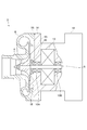
- Drawing 1 is a mimetic diagram showing a rough section composition of electric supercharger 2 concerning one embodiment.
- the electric supercharger 2 includes a compressor impeller 4, a rotating shaft 6, an impeller casing 8, bearings 10 ⁇ / b> A and 10 ⁇ / b> B, a motor 12, a back side casing 14 (stationary member), and a mechanical seal 20. Is provided.
- the axial direction of the compressor impeller 4 is simply referred to as “axial direction”
- the radial direction of the compressor impeller 4 is simply referred to as “radial direction”
- the circumferential direction of the compressor impeller 4 is simply referred to as “circumferential direction”.
- the impeller casing 8 is formed so as to surround the compressor impeller 4, and is configured to guide intake air to the inlet of the compressor impeller 4 and to discharge air compressed by the compressor impeller 4.
- Each of the bearings 10A and 10B is configured as, for example, a rolling bearing so as to rotatably support the rotating shaft 6, and grease is provided as a lubricant around a rolling element held between an inner ring and an outer ring (not shown). It is configured as a sealed grease lubrication type bearing.
- the bearing 10 ⁇ / b> A is positioned between the mechanical seal 20 and the motor 12 in the axial direction, and is positioned between the rear casing 14 and the rotating shaft 6 in the radial direction.
- the bearing 10B is located on the opposite side of the bearing 10A across the motor 12 in the axial direction, and is located between the back casing 14 and the rotary shaft 6 in the radial direction.
- the motor 12 is configured to transmit a driving force to the compressor impeller 4 via the rotary shaft 6.
- the motor 12 is located between the bearing 10A and the bearing 10B in the axial direction.
- the rear casing 14 is configured to face the rear surface 16 of the compressor impeller 4 through a gap and surround the mechanical seal 20, the bearings 10A and 10B, and the motor 12. Further, the back casing 14 includes an inverter accommodating portion 18 for accommodating an inverter (not shown) on the opposite side of the motor 12 with the bearing 10B interposed therebetween.
- the mechanical seal 20 is positioned between the back surface 16 of the compressor impeller 4 and the bearing 10A in the axial direction, and is configured to seal a gap between the rotary shaft 6 and the back side casing 14.
- FIG. 2 is a schematic diagram illustrating a schematic cross-sectional configuration in the vicinity of the back surface 16 of the compressor impeller 4 in the electric supercharger 2 (2A) according to the embodiment, and illustrates a configuration example of the mechanical seal 20.
- FIG. FIG. 3 is a diagram illustrating a state when the compressor impeller 4 rotates in the electric supercharger 2 (2A) illustrated in FIG.
- the mechanical seal 20 includes a stationary ring 22, a rotating ring 24, and a biasing member 26.
- the stationary ring 22 is configured in a ring shape along the circumferential direction and is supported by the rear casing 14.
- the stationary ring 22 is disposed at a position between the rotating ring 24 and the back side casing 14 and between the back side casing 14 and the rotating shaft 6.
- the rotary ring 24 is provided between the back surface 16 of the compressor impeller 4 and the fixed ring 22, and is configured in an annular shape along the circumferential direction so as to face the fixed ring 22 so as to be able to contact in the axial direction. .
- the rotating ring 24 is configured to protrude outward from the rotating shaft 6 in the radial direction, and rotates together with the rotating shaft 6.
- the biasing member 26 is configured to bias one of the fixed ring 22 and the rotating ring 24 toward the other of the fixed ring 22 and the rotating ring 24.
- the urging member 26 is formed of an elastic member (for example, a coil spring, a disc spring, or rubber), and the fixed ring 22 and the rear side are urged to urge the fixed ring 22 toward the rotating ring 24. It is interposed between the casing 14.
- a facing surface 32 that is one of the surface 28 of the rotating ring 24 that faces the fixed ring 22 and the surface 30 of the fixed ring 22 that faces the rotating ring 24 (in the form shown, the fixed ring 22 is included in the rotating ring 24).
- Grooves 34 are formed in the opposing surface 28).
- the groove 34 of the facing surface 32 has a space 36 (a space between the stationary ring 22 and the rotating shaft 6) on the radially inner side of the facing surface 32 when the stationary ring 22 and the rotating ring 24 are in contact with each other.
- the groove 34 is located on the inner side in the radial direction from the inner peripheral end 40 of the contact portion between the fixed ring 22 and the rotary ring 24 on the facing surface 32 in a state where the fixed ring 22 and the rotary ring 24 are in contact with each other. To the position where it does not reach the outer peripheral end 42 of the contact portion between the stationary ring 22 and the rotating ring 24 on the opposing surface 32.
- the stationary ring 22 is pushed toward the biasing member 26 as shown in FIG. 3 by the pressure of the gas in the groove 34 increased by the centrifugal force.
- the stationary ring 22 and the rotating ring 24 are not in contact with each other, but the pressure in the space 38 inside the facing surface 32 becomes higher than the pressure in the space 38 outside the facing surface 32, so Intrusion of the leakage flow into 10A can be suppressed. Therefore, the inflow of the leakage flow into the electric device such as the motor 12 can be suppressed. Therefore, generation
- FIG. 4 is a schematic diagram illustrating a schematic cross-sectional configuration in the vicinity of the rear surface 16 of the compressor impeller 4 in the electric supercharger 2 (2B) according to the embodiment.
- FIG. 5 is a diagram illustrating a configuration example of the ribs 44 illustrated in FIG. 4, and illustrates an example of the arrangement of the ribs 44 when viewed in the axial direction.
- FIG. 6 is a diagram illustrating a configuration example of the ribs 44 illustrated in FIG. 4, and illustrates an example of the arrangement of the ribs 44 when viewed in the axial direction.
- a plurality of ribs 44 are provided on the back surface 16 of the compressor impeller 4 at intervals in the circumferential direction.
- the centrifugal force outward in the radial direction acts on the air in the back gap g when the compressor impeller 4 rotates, thereby reducing the pressure in the inner peripheral portion of the back gap g. be able to.
- invasion of the leak flow from the back surface gap g to 10 A of bearings can be suppressed, and the inflow of this leak flow to electric equipments, such as a motor, can be suppressed.
- each of the ribs 44 extends along a direction intersecting the circumferential direction.
- the plurality of ribs 44 extend radially along a direction (radial direction) orthogonal to the circumferential direction.
- each of the ribs 44 has a wing shape. According to such a configuration, the air flow outward in the radial direction in the rear gap g when the compressor impeller 4 rotates can be effectively formed by the blade-shaped ribs 44. Thereby, the penetration
- the rib 44 is arranged such that the outer peripheral end 46 of the rib 44 is positioned upstream of the inner peripheral end 48 of the rib 44 in the rotational direction of the compressor impeller 4. , Extending in a direction inclined with respect to the radial direction.
- FIG. 7 is a schematic diagram showing a schematic cross-sectional configuration in the vicinity of the back surface 16 of the compressor impeller 4 in the electric supercharger 2 (2C) according to the embodiment.
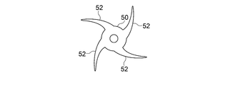
- FIG. 8 is a diagram illustrating a configuration example of the rotating unit 50 illustrated in FIG. 7, and illustrates an example of the shape of the rotating unit 50 when viewed in the axial direction.
- FIG. 9 is a diagram illustrating a configuration example of the rotating unit 50 illustrated in FIG. 7, and illustrates an example of the shape of the rotating unit 50 when viewed in the axial direction.
- FIG. 10 is a diagram illustrating a configuration example of the rotating unit 50 illustrated in FIG. 7, and illustrates an example of the shape of the rotating unit 50 when viewed in the axial direction.
- the rotating part 50 is further provided.
- the shape of the rotation part 50 is not specifically limited, For example, as shown in FIG. 8, an annular shape may be sufficient, and as shown in FIG.9 and FIG. Projections 52 (four projections 52 in the illustrated form).
- the protrusions 52 may protrude radially along the radial direction as shown in FIG. 9, or may have a tapered shape protruding obliquely with respect to the radial direction as shown in FIG.
- FIG. 11 is a schematic diagram showing a schematic cross-sectional configuration in the vicinity of the rear surface 16 of the compressor impeller 4 in the electric supercharger 2 (2D) according to the embodiment.
- FIG. 12 is a diagram showing the relationship between the radial position R and the gauge pressure P of the back gap g, and the broken line shows the electric supercharger 2 (2A) that does not include the abradable coating layer 90. The solid line shows the electric supercharger 2 (2D) in which the abradable coating layer 90 is formed on the facing surface 21.
- FIG. 13 is a schematic diagram illustrating a schematic cross-sectional configuration in the vicinity of the back surface 16 of the compressor impeller 4 in the electric supercharger 2 (2E) according to the embodiment.
- At least a part of the facing surface 21 of the back casing 14 that faces the back surface 16 of the compressor impeller 4 is formed.
- FIG. 12 is a diagram showing a schematic relationship between the radial direction position R and the gauge pressure P of the back surface gap g.
- the broken line indicates the electric supercharger 2 (2A) that does not include the abradable coating layer 90.
- the solid line shows the electric supercharger 2 (2D) in which the abradable coating layer 90 is formed on the facing surface 21.
- the clearance C between the rear surface 16 and the rear casing 14 in the electric supercharger 2 (2D) is set to be smaller than the clearance between the rear surface 16 and the rear casing 14 in the electric supercharger 2 (2A). Yes.
- the electric supercharger 2 by promoting the pressure drop inward in the radial direction in the back gap g, the pressure in the inner peripheral portion of the back gap g (pressure in the vicinity of the mechanical seal 20), The pressure difference in the axial direction from the pressure in the vicinity of the bearing 10A can be reduced, and the leakage flow from the back gap g to the bearing 10A side (the mechanical seal 20 side) can be suppressed. Thereby, the inflow of the leakage flow to electric devices, such as the motor 12 and an inverter (not shown), can be suppressed. Therefore, generation
- the compressor impeller 4 receives a thrust force in the axial direction when compressing air to the upstream side in the air suction direction (left side in the figure).
- the compressor impeller 4 is Since the pressure of the back surface gap g can be reduced, the axial thrust force can be reduced.
- the spring of the biasing member 26 necessary for appropriately moving the stationary ring 22 by promoting the pressure drop inward in the radial direction in the back gap g and lowering the pressure in the inner peripheral portion of the back gap g.
- the force can be reduced, and the progress of wear due to the rubbing between the stationary ring 22 and the rotating ring 24 can be suppressed.
- the ratio C / Ri between the clearance C between the rear surface 16 of the compressor impeller 4 and the rear casing 14 and the outer diameter Ri of the compressor impeller 4 is less than 0.5%.
- the abradable coating layer 90 is formed on at least a part of the back surface 16 of the compressor impeller 4. Further, the ratio C / Ri between the clearance C between the rear surface 16 of the compressor impeller 4 and the rear casing 14 and the outer diameter Ri of the compressor impeller 4 is less than 0.5%.
- the bearing 10A side (mechanical seal) from the back gap g. 20 side) can be prevented from entering the leakage flow.
- the inflow of the leakage flow to electric devices, such as the motor 12 and an inverter (not shown) can be suppressed. Therefore, generation
- the pressure in the rear gap g can be reduced by reducing the clearance C, the axial thrust force in the compressor impeller 4 can be reduced.
- the spring of the biasing member 26 necessary for appropriately moving the stationary ring 22 by promoting the pressure drop inward in the radial direction in the back gap g and lowering the pressure in the inner peripheral portion of the back gap g.
- the force can be reduced, and the progress of wear due to the rubbing between the stationary ring 22 and the rotating ring 24 can be suppressed.
- the pressure inside the back side casing 14 is adjusted by communicating the inside and outside of the back side casing 14.
- a communication hole 53 is further provided as an internal pressure adjusting mechanism configured to do this.
- the communication hole 53 may be provided on the compressor side of the rear casing 14 as shown in FIG. 14, for example, or may be provided on the inverter side as shown in FIG. 15, or may be provided on both sides thereof.
- the position, shape, hole diameter and other dimensions of the communication hole 53 are optimally designed according to the size of the electric supercharger 2.
- the rear side casing 14 is made of dust, water, oil, etc. while adjusting the pressure and temperature inside the rear side casing 14 on the outer end side of the communication hole 53.
- the waterproof ventilation filter 55 which protects the inside is provided.
- the mechanical seal 20 can stably suppress the leakage flow that has passed through the back gap g from entering the bearings 10 ⁇ / b> A and 10 ⁇ / b> B.
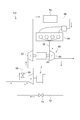
- FIG. 16 is a diagram showing a schematic configuration of the engine apparatus 100 to which the above-described electric supercharger 2 (2A to 2E) can be suitably applied.
- FIG. 16 shows an embodiment of the engine apparatus 100 when the electric supercharger 2 is used as a high-pressure supercharger of a two-stage supercharging system.
- the engine apparatus 100 shown in FIG. 16 includes an engine 54, an intake passage 56 through which intake gas supplied to the engine 54 flows, an exhaust passage 58 through which exhaust gas discharged from the engine 54 flows, a turbocharger 60, and The above-described electric supercharger 2 is provided.
- the turbocharger 60 includes an exhaust turbine 64 disposed in the exhaust passage 58, a compressor 62 disposed in the intake passage 56, and a turbine shaft 63 that connects the exhaust turbine 64 and the compressor 62.
- the turbocharger 60 is configured to supercharge the intake gas flowing through the intake passage 56 when the exhaust turbine 64 is driven by the exhaust gas discharged from the engine 54 and the compressor 62 is coaxially driven via the turbine shaft 63. Has been.
- the electric supercharger 2 is arranged on the downstream side of the compressor 62 in the intake passage 56, and the intake gas compressed by the compressor 62 of the turbocharger 60 is supplied to the compressor impeller 4 of the electric supercharger 2. .
- the engine device 100 of the present embodiment is configured as a two-stage supercharging system in which the turbocharger 60 is disposed as a low pressure supercharger and the electric supercharger 2 is disposed as a high pressure supercharger.
- a bypass intake passage 66 that bypasses the electric supercharger 2 is connected to the intake passage 56.
- a bypass valve 68 is disposed in the bypass intake passage 66. The flow rate of the intake gas flowing into the electric supercharger 2 is controlled by adjusting the valve opening degree of the bypass valve 68.
- an intermediate cooler 70 for cooling the intake gas supplied to the engine 54 is disposed on the downstream side of the electric supercharger 2 in the intake passage 56.
- the engine apparatus 100 is provided with an EGR passage 72 that connects a downstream side of the exhaust turbine 64 in the exhaust passage 58 and an upstream side of the compressor 62 in the intake passage 56.
- An EGR valve 74 is disposed in the EGR passage 72. Then, by adjusting the valve opening of the EGR valve 74, the exhaust gas having a flow rate corresponding to the valve opening returns to the intake passage 56. Then, the intake gas including the recirculated exhaust gas is supplied to the compressor impeller 4 of the electric supercharger 2.
- the bypass valve 68 is closed at the time of engine low speed rotation, and the intake gas boosted by the turbocharger 60 serving as the low pressure stage supercharger is, as indicated by the arrow a, the high pressure stage supercharger. Is supplied to the electric supercharger 2 and further boosted. Therefore, compared with the case where the electric supercharger 2 is arranged in the low pressure stage, the differential pressure between the outer peripheral portion and the inner peripheral portion of the compressor in the electric supercharger 2 is increased, and the above-described rear gap g has a high temperature and high pressure. Intake air enters.
- the bypass valve 68 is opened and the electric supercharger 2 is stopped during high-speed rotation of the engine.
- the intake gas boosted by the turbocharger 60 as a low-pressure supercharger is supplied to the downstream side of the electric supercharger 2 through the bypass intake passage 66 as indicated by an arrow b.
- the boost pressure of the turbocharger 60 generates a differential pressure between the outer peripheral portion and the inner peripheral portion of the compressor in the electric supercharger 2, and the intake air enters the above-described rear gap g.
- the high-temperature and high-pressure intake air can be prevented from entering the bearing side from the back gap g. , 10B, the motor 12 and the like can be effectively prevented from occurring.
- the high-temperature and high-pressure intake air can be prevented from entering the bearing side from the back gap g. , 10B, the motor 12 and the like can be effectively prevented from occurring.
- the present invention is not limited to the above-described embodiments, and includes forms obtained by modifying the above-described embodiments and forms obtained by appropriately combining these forms.
- the back side casing 14 surrounds the mechanical seal 20, the bearings 10A and 10B, and the motor 12, but the configuration of the back side casing 14 is not limited to this. May surround only the mechanical seal 20, and a casing separate from the back side casing 14 may surround the bearings 10A, 10B and the motor 12, or the back side casing 14 may surround only the mechanical seal 20 and the bearing 10A. However, a casing separate from the back side casing 14 may surround the bearing 10 ⁇ / b> B and the motor 12.
- FIG. 17 is a schematic diagram showing a schematic cross-sectional configuration in the vicinity of the rear surface 16 of the compressor impeller 4 in the electric supercharger 2 (2F) according to another invention.
- FIG. 18 is a schematic diagram showing a schematic cross-sectional configuration in the vicinity of the back surface 16 of the compressor impeller 4 in the electric supercharger 2 (2G) according to another invention.
- FIG. 19 is a schematic diagram showing a schematic cross-sectional configuration in the vicinity of the back surface 16 of the compressor impeller 4 in the electric supercharger 2 (2H) according to another invention.
- FIG. 20 is a schematic diagram showing a schematic cross-sectional configuration in the vicinity of the back surface 16 of the compressor impeller 4 in the electric supercharger 2 (2I) according to another invention.
- FIG. 21 is a schematic diagram showing a schematic cross-sectional configuration in the vicinity of the back surface 16 of the compressor impeller 4 in the electric supercharger 2 (2J) according to another invention.
- FIG. 22 is a schematic diagram showing a schematic cross-sectional configuration in the vicinity of the rear surface 16 of the compressor impeller 4 in the electric supercharger 2 (2K) according to another invention.
- the basic configuration of the electric supercharger 2 (2F to 2K) is the same as the basic configuration of the electric supercharger 2 shown in FIG. 1 except that the mechanical seal 20 is not provided. The description will be omitted, and the characteristic configuration of each embodiment will be mainly described.
- the electric supercharger 2 (2F to 2H) is directed radially outward from the rotary shaft 6 between the back surface 16 and the back side casing 14 of the compressor impeller 4. And a rotating portion 76 configured to rotate together with the rotating shaft 6. Further, the outer peripheral end 78 of the rotating portion 76 is located on the radially outer side than the inner peripheral end 80 of the back side casing 14.
- the shape of the rotating part 76 is not particularly limited, but each shape of the rotating part 50 described with reference to FIGS. 8 to 10 can be adopted.
- the rotation part 76 may be arrange
- the rotating portion 76 has a convex portion 84 protruding in the axial direction so as to enter the inside of the concave portion 82 as shown in FIG. You may have.
- the electric supercharger 2 (2I) is obtained by replacing the mechanical seal 20 in the electric supercharger 2 (2B) shown in FIG.
- the electric supercharger 2 (2I) like the electric supercharger 2 (2B), a plurality of ribs 44 are provided on the back surface 16 of the compressor impeller 4 at intervals in the circumferential direction.
- the seal unit 9 includes a sleeve 86 and at least one piston ring 88 (two piston rings 88 in the illustrated form).
- the sleeve 86 is provided so that one end side thereof is in contact with the back surface 16 of the compressor impeller 4 in a state of being fitted to the rotary shaft 6.
- the piston ring 88 is fitted into an annular groove provided on the outer peripheral surface of the sleeve 86 and is in contact with the rear casing 14 to seal a gap between the rotary shaft 6 and the rear casing 14.
- the electric supercharger 2 (2J) is obtained by replacing the mechanical seal 20 in the electric supercharger 2 (2D) shown in FIG.
- the electric supercharger 2 (2J) as in the electric supercharger 2 (2D), at least a part of the opposed surface 21 that faces the back surface 16 of the compressor impeller 4 in the rear casing 14 (opposed in the illustrated form).
- the abradable coating layer 90 is formed on the entire surface 21).
- the compressor impeller 4 receives a thrust force in the axial direction in the air suction direction (left side in the figure) when compressing air.
- the electric supercharger 2 (2J) Since the impeller 4 can reduce the pressure of the back surface gap g, the axial thrust force can be reduced.
- the electric supercharger 2 (2K) is obtained by replacing the mechanical seal 20 in the electric supercharger 2 (2E) shown in FIG.
- the abradable coating layer 90 is formed on at least a part of the back surface 16 of the compressor impeller 4 as in the electric supercharger 2 (2E).
- the compressor impeller 4 receives a thrust force in the axial direction toward the upstream side (left side in the drawing) of the air when compressing the air.
- the electric supercharger 2 (2K) Since the impeller 4 can reduce the pressure of the back surface gap g, the axial thrust force can be reduced.
- the electric supercharger 2 (2A to 2E) can be suitably used as the high-pressure supercharger of the two-stage supercharging system, but as shown in FIG.
- the electric supercharger 2 (2A to 2K) may be used as the low pressure supercharger of the two-stage supercharging system.
- the electric supercharger 2 is disposed on the upstream side of the compressor 62 in the intake passage 56, and the intake gas compressed by the electric supercharger 2 is compressed by the compressor 62 of the turbocharger 60. Supplied to.
- the engine device 110 is configured as a two-stage supercharging system in which the turbocharger 60 is disposed as a high pressure supercharger and the electric supercharger 2 is disposed as a low pressure supercharger.
- a bypass intake passage 66 that bypasses the electric supercharger 2 is connected to the intake passage 56.
- a bypass valve 68 is disposed in the bypass intake passage 66. The flow rate of the intake gas flowing into the electric supercharger 2 is controlled by adjusting the valve opening degree of the bypass valve 68.
- an intermediate cooler 70 for cooling the intake gas supplied to the engine 54 is disposed on the downstream side of the compressor 62 in the intake passage 56.
- the engine device 110 is provided with an EGR passage 72 that connects a downstream side of the exhaust turbine 64 in the exhaust passage 58 and an upstream side of the electric supercharger 2 in the intake passage 56.
- An EGR valve 74 is disposed in the EGR passage 72. Then, by adjusting the valve opening of the EGR valve 74, the exhaust gas having a flow rate corresponding to the valve opening returns to the intake passage 56. Then, the intake gas including the recirculated exhaust gas is supplied to the compressor impeller 4 of the electric supercharger 2.
- the bypass valve 68 is closed at the time of engine low-speed rotation, and the intake gas boosted by the electric supercharger 2 as the low-pressure stage supercharger is high-pressure stage excess as shown by an arrow c.
- the pressure is supplied to a compressor 62 of a turbocharger 60 as a feeder and further boosted. Therefore, the boost pressure of the electric supercharger 2 is applied between the outer peripheral portion and the inner peripheral portion of the compressor in the electric supercharger 2, and the intake air enters the back gap g described above.
- the bypass valve 68 is opened and the electric supercharger 2 is stopped at the time of high-speed engine rotation.
- the intake gas is supplied to the compressor 62 through the bypass intake passage 66 as shown by the arrow d, the intake air hardly enters the rear gap g of the electric supercharger 2.
Landscapes
- Engineering & Computer Science (AREA)
- Mechanical Engineering (AREA)
- General Engineering & Computer Science (AREA)
- Chemical & Material Sciences (AREA)
- Combustion & Propulsion (AREA)
- Structures Of Non-Positive Displacement Pumps (AREA)
- Supercharger (AREA)
Abstract
電動過給機において、コンプレッサインペラと、コンプレッサインペラに回転軸を介して駆動力を伝達するよう構成されたモータと、コンプレッサインペラの背面と隙間を介して対向するとともに回転軸を囲繞する背面側ケーシングと、回転軸を回転可能に支持するように背面側ケーシングと回転軸との間に設けられた軸受と、コンプレッサインペラの軸方向においてコンプレッサインペラの背面と軸受との間に位置し、回転軸と背面側ケーシングとの隙間をシールするよう構成されたメカニカルシールと、を備える。
Description
本開示は、電動過給機に関する。
自動車等のエンジン装置において、エンジン燃費や効率の向上を図るため、エンジンから排出される排気ガスによって排気タービンを駆動させ、これにより吸気通路に配置されているコンプレッサを同軸駆動させて、エンジンに供給する吸気ガスを圧縮する「過給」が行われている。
このターボチャージャによる過給では、ターボラグと呼ばれるエンジン低速回転時における応答遅れにより、エンジン低速回転時におけるトルクや出力が問題となる。このターボラグによる応答遅れを補完する技術として、排気ガスによって駆動するターボチャージャ及び電動機によって駆動する電動過給機を備える二段過給システムが公知である(特許文献1)。
ところで、電動過給機では、ターボチャージャと異なりモータによってコンプレッサが駆動されるため、コンプレッサの後方(コンプレッサインペラに対して軸受側)にモータやインバータ基板等の機器が設置される。
このため、コンプレッサインペラの背面とケーシングとの間を通った漏れ流れが軸受側に侵入すると、モータやインバータ基板等の機器に影響を与える恐れがある。
特に、EGRを備えた二段過給システムにおいて排気ガスの一部を再循環させる場合や、中間冷却機を使用する場合、及びブローバイガスをコンプレッサの入口に戻す場合等には、コンプレッサの入口から凝縮水を含む空気が吸い込まれるため、コンプレッサインペラの背面とケーシングとの間を通った漏れ流れが軸受側に侵入すると、モータやインバータ等の機器の動作に不具合が生じる恐れがある。
また、特に、二段過給システムの高圧段に電動過給機を適用する場合には、高温高圧の空気がコンプレッサの入口から流入するため、コンプレッサインペラの背面とケーシングとの間を通った漏れ流れが軸受側に侵入すると、軸受やモータ等の機器に不具合が生じる恐れがある。
本発明の少なくとも一実施形態は、上述したような従来の課題に鑑みなされたものであって、その目的とするところは、コンプレッサインペラの背面とケーシングとの間を通った漏れ流れの軸受側への侵入を抑制可能な電動過給機を提供することである。
(1)本発明の少なくとも一実施形態に係る電動過給機は、コンプレッサインペラと、前記コンプレッサインペラに回転軸を介して駆動力を伝達するよう構成されたモータと、前記コンプレッサインペラの背面と隙間を介して対向するとともに前記回転軸を囲繞する背面側ケーシングと、前記回転軸を回転可能に支持するように前記背面側ケーシングと前記回転軸との間に設けられた軸受と、前記コンプレッサインペラの軸方向において前記コンプレッサインペラの背面と前記軸受との間に位置し、前記回転軸と前記背面側ケーシングとの隙間をシールするよう構成されたメカニカルシールと、を備える。
上記(1)に記載の電動過給機によれば、背面と背面側ケーシングとの隙間(以下、「背面隙間」という)を通った漏れ流れの軸受への侵入をメカニカルシールによって効果的に抑制し、モータ等の電気機器への該漏れ流れの流入を抑制することができる。よって、これらの電気機器の動作不良等の発生を抑制し、電動過給機を安定的に運転することができる。
(2)幾つかの実施形態では、上記(1)に記載の電動過給機において、前記メカニカルシールは、前記背面側ケーシングに支持された固定環と、前記回転軸から前記コンプレッサインペラの径方向における外側に向けて突出し、前記固定環に対して前記コンプレッサインペラの軸方向に当接可能に対向し、前記回転軸とともに回転するよう構成された回転環と、前記回転環と前記固定環のうち一方を前記回転環と前記固定環のうち他方に向けて付勢する付勢部材と、を備え、前記回転環のうち前記固定環に対向する面と前記固定環のうち前記回転環と対向する面の一方である対向面には溝が形成される。
上記(2)に記載の電動過給機によれば、コンプレッサインペラの回転が停止しているときには、回転環と固定環のうち一方が回転環と固定環のうち他方に付勢部材によって押し付けられることにより、メカニカルシールが接触シールとして機能する。これにより背面隙間から軸受への漏れ流れの侵入を抑制し、モータ等の電気機器への該漏れ流れの流入を抑制することができる。よって、これらの電気機器の動作不良等の発生を抑制し、電動過給機を安定的に運転することができる。
また、コンプレッサインペラが回転しているときには、遠心力によって昇圧した溝内の気体の圧力によって、付勢部材の付勢力に抗して固定環と回転環とが引き離される。これにより固定環と回転環とは非接触となるが、対向面の内側の空間の圧力が対向面の外側の空間の圧力よりも高くなることにより、背面隙間から軸受への漏れ流れの侵入を抑制することができる。したがって、モータ等の電気機器への該漏れ流れの流入を抑制することができる。よって、これらの電気機器の動作不良等の発生を抑制し、電動過給機を安定的に運転することができる。
また、コンプレッサインペラが回転しているときには、遠心力によって昇圧した溝内の気体の圧力によって、付勢部材の付勢力に抗して固定環と回転環とが引き離される。これにより固定環と回転環とは非接触となるが、対向面の内側の空間の圧力が対向面の外側の空間の圧力よりも高くなることにより、背面隙間から軸受への漏れ流れの侵入を抑制することができる。したがって、モータ等の電気機器への該漏れ流れの流入を抑制することができる。よって、これらの電気機器の動作不良等の発生を抑制し、電動過給機を安定的に運転することができる。
(3)幾つかの実施形態では、上記(1)又は(2)に記載の電動過給機において、前記コンプレッサインペラの前記背面には、前記コンプレッサインペラの周方向に間隔をあけて複数のリブが設けられる。
上記(3)に記載の電動過給機によれば、複数のリブを設けたことによってコンプレッサインペラの回転時に背面隙間の空気に径方向外側への遠心力が作用し、背面隙間の内周部の圧力を低くすることができる。これにより背面隙間から軸受への漏れ流れの侵入を抑制し、モータ等の電気機器への該漏れ流れの流入を抑制することができる。また、上記(2)に記載の電動過給機に適用される場合には、背面隙間の内周部の圧力を低くすることにより、固定環を適切に移動させるために必要な付勢部材のバネ力を低減することが可能となり、固定環と回転環との摺擦に起因する摩耗の進行を抑制することができる。
(4)幾つかの実施形態では、上記(3)に記載の電動過給機において、前記リブは、前記コンプレッサインペラの周方向と交差する方向に沿って延設される。
上記(4)に記載の電動過給機によれば、周方向と交差する方向に延在する複数のリブがコンプレッサインペラとともに回転するため、背面隙間の空気に径方向外側への遠心力を効果的に作用させ、背面隙間の内周部の圧力を低くすることができる。これにより背面隙間から軸受への漏れ流れの侵入を抑制し、モータ等の電気機器への該漏れ流れの流入を抑制することができる。
(5)幾つかの実施形態では、上記(3)又は(4)に記載の電動過給機において、前記リブは、翼形状を有する。
上記(5)に記載の電動過給機によれば、コンプレッサインペラの回転時に背面隙間における径方向外側への空気流れを翼形状のリブによって効果的に形成することができる。これにより背面隙間から軸受への漏れ流れの侵入を抑制し、モータ等の電気機器への該漏れ流れの流入を抑制することができる。
(6)幾つかの実施形態では、上記(3)乃至(5)の何れかに記載の電動過給機において、前記リブは、当該リブの外周端が当該リブの内周端より前記コンプレッサインペラの回転方向の上流側に位置するように、前記コンプレッサインペラの径方向に対して傾斜した方向に延設される。
上記(6)に記載の電動過給機によれば、リブを上記の方向に傾斜させることにより、コンプレッサインペラの回転中に径方向外側からリブの間に空気が流入しにくくなる。これにより背面隙間から軸受への漏れ流れの侵入を抑制し、モータ等の電気機器への該漏れ流れの流入を抑制することができる。
(7)幾つかの実施形態では、上記(1)乃至(6)の何れかに記載の電動過給機において、前記メカニカルシールと前記コンプレッサインペラの前記背面との間において前記回転軸から前記コンプレッサインペラの径方向における外側に向けて突出し、前記回転軸とともに回転するよう構成された回転部を更に備える。
上記(7)に記載の電動過給機によれば、コンプレッサインペラの回転時に、回転部の回転に伴って背面隙間の空気に径方向外側への遠心力が作用し、背面隙間の内周部の圧力を低くすることができる。これにより背面隙間から軸受への漏れ流れの侵入を抑制し、モータ等の電気機器への該漏れ流れの流入を抑制することができる。また、上記(2)に記載の電動過給機に適用される場合には、背面隙間の内周部の圧力を低くすることにより、固定環を適切に移動させるために必要な付勢部材のバネ力を低減することが可能となり、固定環と回転環との摺擦に起因する摩耗の進行を抑制することができる。
(8)幾つかの実施形態では、上記(1)乃至(7)の何れかに記載の電動過給機において、前記コンプレッサインペラの前記背面の少なくとも一部、又は前記背面側ケーシングのうち前記コンプレッサインペラの前記背面に対向する面の少なくとも一部には、アブレーダブルコーティング層が形成される。
上記(8)に記載の電動過給機によれば、コンプレッサインペラの背面の少なくとも一部にアブレーダブルコーティング層が形成される場合には、背面側ケーシングのうちコンプレッサインペラの背面に対向する面とコンプレッサインペラの背面に形成されたアブレーダブルコーティング層とが接触しても、コンプレッサインペラの回転時にアブレーダブルコーティング層が削れるため、背面と背面側ケーシングとのクリアランスを小さくすることができる。
また、背面側ケーシングのうちコンプレッサインペラの背面に対向する面の少なくとも一部にアブレーダブルコーティング層が形成される場合には、背面側ケーシングのうちコンプレッサインペラの背面に対向する面に形成されたアブレーダブルコーティング層とコンプレッサインペラの背面とが接触しても、コンプレッサインペラの回転時にアブレーダブルコーティング層が削れるため、背面と背面側ケーシングとのクリアランスを小さくすることができる。
このため、背面隙間における径方向内側への圧力降下を促進することができる。これにより、背面隙間のうち内周部の圧力と、軸受付近の圧力との軸方向の圧力差を小さくすることができ、背面隙間から軸受側への漏れ流れの侵入を抑制することができる。これにより、モータやインバータ等の電気機器への漏れ流れの流入を抑制することができる。よって、これらの電気機器の動作不良等の発生を抑制し、電動過給機を安定的に運転することができる。
また、コンプレッサインペラは、空気を圧縮する際に軸方向において空気の吸い込み方向上流側へのスラスト力を受けることになるが、上記電動過給機では、コンプレッサインペラは背面隙間の圧力を低下させることができるため、軸方向のスラスト力を低減することができる。
また、背面隙間における径方向内側への圧力降下を促進して背面隙間の内周部の圧力を低くすることにより、メカニカルシールの固定環を適切に移動させるために必要な付勢部材のバネ力を低減することが可能となり、固定環と回転環との摺擦に起因する摩耗の進行を抑制することができる。
(9)幾つかの実施形態では、上記(8)の何れかに記載の電動過給機において、前記コンプレッサインペラの前記背面と前記背面側ケーシングとの間の隙間の大きさGと、前記コンプレッサインペラの外径Rとの比G/Rが、0.5%未満である。
上記(9)に記載の電動過給機によれば、背面隙間における径方向内側への圧力降下を効果的に促進することができる。本願発明者によれば、アブレーダブルコーティング層を設けてC/Riをに設定した場合と、アブレーダブルコーティング層を設けずにC/Riを0.25%に設定した場合を比較すると、前者の方が後者よりも背面隙間の内周部の圧力を26%減少できることが確認された。
(10)幾つかの実施形態では、上記(1)乃至(9)の何れかに記載の電動過給機において、前記背面側ケーシングの内外を連通することにより前記背面側ケーシング内の圧力を調整するよう構成された内圧調整機構を更に備える。
上記(10)に記載の電動過給機によれば、上記(1)乃至(9)の何れかに記載の電動過給機において、背面隙間の内周部の圧力が低くなった場合においても、背面側ケーシングの内外の圧力を内圧調整機構によって調整することにより、メカニカルシールの前後の圧力バランスを安定させることができる。これにより、背面隙間を通った漏れ流れの軸受への侵入をメカニカルシールによって安定的に抑制することができる。
本発明の少なくとも一つの実施形態によれば、コンプレッサインペラの背面とケーシングとの間を通った漏れ流れの軸受側への侵入を抑制可能な電動過給機が提供される。
以下、添付図面を参照して本発明の幾つかの実施形態について説明する。ただし、実施形態として記載されている又は図面に示されている構成部品の寸法、材質、形状、その相対的配置等は、本発明の範囲をこれに限定する趣旨ではなく、単なる説明例にすぎない。
例えば、「ある方向に」、「ある方向に沿って」、「平行」、「直交」、「中心」、「同心」或いは「同軸」等の相対的或いは絶対的な配置を表す表現は、厳密にそのような配置を表すのみならず、公差、若しくは、同じ機能が得られる程度の角度や距離をもって相対的に変位している状態も表すものとする。
例えば、「同一」、「等しい」及び「均質」等の物事が等しい状態であることを表す表現は、厳密に等しい状態を表すのみならず、公差、若しくは、同じ機能が得られる程度の差が存在している状態も表すものとする。
例えば、四角形状や円筒形状等の形状を表す表現は、幾何学的に厳密な意味での四角形状や円筒形状等の形状を表すのみならず、同じ効果が得られる範囲で、凹凸部や面取り部等を含む形状も表すものとする。
一方、一の構成要素を「備える」、「具える」、「具備する」、「含む」、又は、「有する」という表現は、他の構成要素の存在を除外する排他的な表現ではない。
図1は、一実施形態に係る電動過給機2の概略的な断面構成を示す模式図である。
図1に示す例示的な形態では、電動過給機2は、コンプレッサインペラ4、回転軸6、インペラケーシング8、軸受10A,10B、モータ12、背面側ケーシング14(静止部材)、及びメカニカルシール20を備える。
図1に示す例示的な形態では、電動過給機2は、コンプレッサインペラ4、回転軸6、インペラケーシング8、軸受10A,10B、モータ12、背面側ケーシング14(静止部材)、及びメカニカルシール20を備える。
以下では、コンプレッサインペラ4の軸方向を単に「軸方向」といい、コンプレッサインペラ4の径方向を単に「径方向」といい、コンプレッサインペラ4の周方向を単に「周方向ということとする。
インペラケーシング8は、コンプレッサインペラ4を囲繞するよう形成されており、コンプレッサインペラ4の入口に吸入空気を導くとともに、コンプレッサインペラ4によって圧縮された空気を吐出するように構成されている。
軸受10A,10Bの各々は、回転軸6を回転可能に支持するように例えば転がり軸受として構成されており、不図示の内輪と外輪の間に保持された転動体の周囲に潤滑材としてグリースが封入されたグリース潤滑方式の軸受として構成されている。軸受10Aは、軸方向においてメカニカルシール20とモータ12との間に位置し、径方向において背面側ケーシング14と回転軸6との間に位置する。軸受10Bは、軸方向においてモータ12を挟んで軸受10Aと反対側に位置し、径方向において背面側ケーシング14と回転軸6との間に位置する。
モータ12は、コンプレッサインペラ4に回転軸6を介して駆動力を伝達するよう構成されている。モータ12は、軸方向において軸受10Aと軸受10Bとの間に位置する。
背面側ケーシング14は、コンプレッサインペラ4の背面16と隙間を介して対向するとともに、メカニカルシール20、軸受10A,10B及びモータ12を囲繞するよう構成されている。また、背面側ケーシング14は、軸受10Bを挟んでモータ12と反対側に、インバータ(不図示)を収容するためのインバータ収容部18を含む。
メカニカルシール20は、軸方向においてコンプレッサインペラ4の背面16と軸受10Aとの間に位置し、回転軸6と背面側ケーシング14との隙間をシールするよう構成される。
図2は、一実施形態に係る電動過給機2(2A)における、コンプレッサインペラ4の背面16近傍の概略的な断面構成を示す模式図であり、メカニカルシール20の構成例を示している。図3は、図2に示した電動過給機2(2A)における、コンプレッサインペラ4の回転時の状態を示す図である。
幾つかの実施形態では、例えば図2及び図3に示すように、メカニカルシール20は、固定環22、回転環24、及び付勢部材26を含む。
固定環22は、周方向に沿って環状に構成されるとともに背面側ケーシング14に支持されている。固定環22は、回転環24と背面側ケーシング14との間、かつ背面側ケーシング14と回転軸6との間の位置に配置されている。
回転環24は、コンプレッサインペラ4の背面16と固定環22との間に設けられ、固定環22に対して軸方向に当接可能に対向するように周方向に沿って環状に構成されている。回転環24は、回転軸6から径方向における外側に向けて突出するよう構成されており、回転軸6とともに回転する。
付勢部材26は、固定環22と回転環24のうち一方を固定環22と回転環24のうち他方に向けて付勢するよう構成されている。図示する形態では、付勢部材26は弾性部材(例えばコイルばね、皿ばね又はゴム等)により構成されており、固定環22を回転環24に向けて付勢するように固定環22と背面側ケーシング14との間に介装されている。
また、回転環24のうち固定環22に対向する面28と固定環22のうち回転環24と対向する面30の一方である対向面32(図示する形態では回転環24のうち固定環22に対向する面28)には溝34が形成されている。対向面32の溝34は、図2に示すように、固定環22と回転環24とが当接した状態において、対向面32の径方向内側の空間36(固定環22と回転軸6との間の空間)に連通するとともに対向面32の径方向外側の空間38(背面16と背面側ケーシング14との背面隙間gのうち固定環22の外側部分)に連通しないように形成されている。すなわち、溝34は、固定環22と回転環24とが当接した状態において、対向面32における固定環22と回転環24との当接部の内周端40よりも径方向における内側の位置から、対向面32における固定環22と回転環24との当接部の外周端42に達しない位置まで設けられている。
かかる構成によれば、コンプレッサインペラ4の回転が停止しているときには、図2に示すように、付勢部材26が固定環22を回転環24に押し付けることにより、メカニカルシール20が接触シールとして機能する。これにより背面隙間gから軸受10Aへの漏れ流れの侵入を抑制し、モータ12等の電気機器への該漏れ流れの流入を抑制することができる。よって、これらの電気機器の動作不良等の発生を抑制し、電動過給機を安定的に運転することができる。
また、コンプレッサインペラ4が回転しているときには、遠心力によって昇圧した溝34内の気体の圧力によって、図3に示すように固定環22が付勢部材26側に押し込まれる。これにより固定環22と回転環24とは非接触となるが、対向面32の内側の空間38の圧力が対向面32の外側の空間38の圧力よりも高くなることにより、背面隙間gから軸受10Aへの漏れ流れの侵入を抑制することができる。したがって、モータ12等の電気機器への該漏れ流れの流入を抑制することができる。よって、これらの電気機器の動作不良等の発生を抑制し、電動過給機を安定的に運転することができる。
次に、図4~図13を用いて電動過給機2の幾つかの変形例について説明する。以下の変形例では、電動過給機2(2A)の各構成と同様の構成については同一の符号を付して説明を省略し、各変形例の特徴的な構成を中心に説明する。
図4は、一実施形態に係る電動過給機2(2B)における、コンプレッサインペラ4の背面16近傍の概略的な断面構成を示す模式図である。図5は、図4に示したリブ44の構成例を示す図であり、軸方向視におけるリブ44の配置の一例を示している。図6は、図4に示したリブ44の構成例を示す図であり、軸方向視におけるリブ44の配置の一例を示している。
幾つかの実施形態では、例えば図4~図6に示すように、コンプレッサインペラ4の背面16には、周方向に間隔をあけて複数のリブ44が設けられる。かかる構成によれば、複数のリブ44を設けたことによってコンプレッサインペラ4の回転時に背面隙間gの空気に径方向外側への遠心力が作用し、背面隙間gの内周部の圧力を低くすることができる。これにより背面隙間gから軸受10Aへの漏れ流れの侵入を抑制し、モータ等の電気機器への該漏れ流れの流入を抑制することができる。また、背面隙間gの内周部の圧力を低くすることにより、固定環22を適切に移動させるために必要な付勢部材26のバネ力を低減することが可能となり、固定環22と回転環24との摺擦に起因する摩耗の進行を抑制することができる。
幾つかの実施形態では、例えば図5及び図6に示すように、リブ44の各々は、周方向と交差する方向に沿って延設される。なお、図5に示す形態では、複数のリブ44は、周方向と直交する方向(径方向)に沿って放射状に延設される。
かかる構成によれば、周方向と交差する方向に延在する複数のリブ44がコンプレッサインペラ4とともに回転するため、背面隙間gの空気に径方向外側への遠心力を効果的に作用させ、背面隙間gの内周部の圧力を低くすることができる。これにより背面隙間gから軸受10Aへの漏れ流れの侵入を抑制し、モータ等の電気機器への該漏れ流れの流入を抑制することができる。
幾つかの実施形態では、例えば図6に示すように、リブ44の各々は、翼形状を有する。かかる構成によれば、コンプレッサインペラ4の回転時に背面隙間gにおける径方向外側への空気流れを翼形状のリブ44によって効果的に形成することができる。これにより背面隙間gから軸受10Aへの漏れ流れの侵入を抑制し、モータ12等の電気機器への該漏れ流れの流入を抑制することができる。
幾つかの実施形態では、例えば図6に示すように、リブ44は、当該リブ44の外周端46が当該リブ44の内周端48よりコンプレッサインペラ4の回転方向の上流側に位置するように、径方向に対して傾斜した方向に延設される。
かかる構成によれば、リブ44を上記の方向に傾斜させることにより、コンプレッサインペラ4の回転中に径方向外側からリブ44の間に空気が流入しにくくなる。これにより背面隙間gから軸受10Aへの漏れ流れの侵入を抑制し、モータ12等の電気機器への該漏れ流れの流入を抑制することができる。
図7は、一実施形態に係る電動過給機2(2C)における、コンプレッサインペラ4の背面16近傍の概略的な断面構成を示す模式図である。図8は、図7に示した回転部50の構成例を示す図であり、軸方向視における回転部50の形状の一例を示している。図9は、図7に示した回転部50の構成例を示す図であり、軸方向視における回転部50の形状の一例を示している。図10は、図7に示した回転部50の構成例を示す図であり、軸方向視における回転部50の形状の一例を示している。
幾つかの実施形態では、例えば図7に示すように、メカニカルシール20とコンプレッサインペラ4の背面16との間において回転軸6から径方向における外側に向けて突出し、回転軸6とともに回転するよう構成された回転部50を更に備える。
かかる構成によれば、コンプレッサインペラ4の回転時に、回転部50の回転に伴って背面隙間gの空気に径方向外側への遠心力が作用し、背面隙間gの内周部の圧力を低くすることができる。これにより背面隙間gから軸受10Aへの漏れ流れの侵入を抑制し、モータ12等の電気機器への該漏れ流れの流入を抑制することができる。また、背面隙間gの内周部の圧力を低くすることにより、固定環22を適切に移動させるために必要な付勢部材26のバネ力を低減することが可能となり、固定環22と回転環24との摺擦に起因する摩耗の進行を抑制することができる。
なお、回転部50の形状は特に限定されず、例えば図8に示すように円環形状であってもよいし、図9及び図10に示すように円環形状から径方向外側に突出する複数の突起52(図示する形態では4つの突起52)を有していてもよい。突起52は、例えば図9に示すように径方向に沿って放射状に突出していてもよいし、図10に示すように径方向に対して斜めに突出する先細形状であってもよい。
図11は、一実施形態に係る電動過給機2(2D)における、コンプレッサインペラ4の背面16近傍の概略的な断面構成を示す模式図である。図12は、半径方向位置Rと背面隙間gのゲージ圧Pとの関係を示す図であり、破線は、アブレーダブルコーティング層90を備えていない電動過給機2(2A)を示しており、実線は、上記対向面21にアブレーダブルコーティング層90が形成された電動過給機2(2D)を示している。図13は、一実施形態に係る電動過給機2(2E)における、コンプレッサインペラ4の背面16近傍の概略的な断面構成を示す模式図である。
幾つかの実施形態では、図11に示すように、背面側ケーシング14のうちコンプレッサインペラ4の背面16に対向する対向面21の少なくとも一部(図示する形態では対向面21の全体)には、アブレーダブルコーティング層90が形成される。
かかる構成によれば、対向面21に形成されたアブレーダブルコーティング層90とコンプレッサインペラ4の背面16とが接触しても、コンプレッサインペラ4の回転時にアブレーダブルコーティング層90が削れるため、背面16と背面側ケーシング14とのクリアランスC(背面16と背面側ケーシング14との距離)を小さくすることができる。これにより、以下に詳述するように、背面隙間gにおける径方向内側への圧力降下を促進することができる。
図12は、半径方向位置Rと背面隙間gのゲージ圧Pとの概略的な関係を示す図であり、破線は、アブレーダブルコーティング層90を備えていない電動過給機2(2A)を示しており、実線は、上記対向面21にアブレーダブルコーティング層90が形成された電動過給機2(2D)を示している。ここで、電動過給機2(2D)における背面16と背面側ケーシング14とのクリアランスCは、電動過給機2(2A)における背面16と背面側ケーシング14とのクリアランスよりも小さく設定されている。
図12に示すように、電動過給機2(2A)と電動過給機2(2D)の何れにおいても背面隙間gでは径方向内側に向かうにつれて圧力が小さくなるが、特に径方向位置Rが小さい領域では電動過給機2(2D)における背面隙間gの圧力が電動過給機2(2A)における背面隙間gの圧力より大幅に低減されている。
このように、電動過給機2によれば、背面隙間gにおける径方向内側への圧力降下を促進することにより、背面隙間gのうち内周部の圧力(メカニカルシール20付近の圧力)と、軸受10A付近の圧力との軸方向の圧力差を小さくすることができ、背面隙間gから軸受10A側(メカニカルシール20側)への漏れ流れの侵入を抑制することができる。これにより、モータ12やインバータ(不図示)等の電気機器への漏れ流れの流入を抑制することができる。よって、これらの電気機器の動作不良等の発生を抑制し、電動過給機2を安定的に運転することができる。
また、コンプレッサインペラ4は、空気を圧縮する際に軸方向において空気の吸い込み方向上流側(図における左側)へのスラスト力を受けることになるが、上記電動過給機2では、コンプレッサインペラ4は背面隙間gの圧力を低下させることができるため、軸方向のスラスト力を低減することができる。
また、背面隙間gにおける径方向内側への圧力降下を促進して背面隙間gの内周部の圧力を低くすることにより、固定環22を適切に移動させるために必要な付勢部材26のバネ力を低減することが可能となり、固定環22と回転環24との摺擦に起因する摩耗の進行を抑制することができる。
一実施形態では、図11において、コンプレッサインペラ4の背面16と背面側ケーシング14とのクリアランスCと、コンプレッサインペラ4の外径Riとの比C/Riが、0.5%未満である。
かかる構成によれば、背面隙間gにおける径方向内側への圧力降下を効果的に促進することができる。本願発明者によれば、アブレーダブルコーティング層90を設けてC/Riを0.8%に設定した場合と、アブレーダブルコーティング層90を設けずにC/Riを0.25%に設定した場合を比較すると、前者の方が後者よりも背面隙間gの内周部の圧力を26%減少できることが確認された。
一実施形態では、図13に示すように、アブレーダブルコーティング層90は、コンプレッサインペラ4の背面16の少なくとも一部に形成される。また、コンプレッサインペラ4の背面16と背面側ケーシング14とのクリアランスCと、コンプレッサインペラ4の外径Riとの比C/Riが、0.5%未満である。
かかる構成によれば、コンプレッサインペラ4の背面16に形成されたアブレーダブルコーティング層90と背面側ケーシング14の対向面21とが接触しても、コンプレッサインペラ4の回転時にアブレーダブルコーティング層90が削れるため、背面16と背面側ケーシング14とのクリアランスCを小さくすることができる。これにより、背面隙間gにおける径方向内側への圧力降下を促進することができる。
したがって、背面隙間gのうち内周部の圧力(メカニカルシール20付近の圧力)と、軸受10A付近の圧力との軸方向の圧力差を小さくすることで、背面隙間gから軸受10A側(メカニカルシール20側)への漏れ流れの侵入を抑制することができる。これにより、モータ12やインバータ(不図示)等の電気機器への漏れ流れの流入を抑制することができる。よって、これらの電気機器の動作不良等の発生を抑制し、電動過給機2を安定的に運転することができる。
また、クリアランスCを小さくすることによって背面隙間gの圧力を低下させることができるため、コンプレッサインペラ4における軸方向のスラスト力を低減することができる。
また、背面隙間gにおける径方向内側への圧力降下を促進して背面隙間gの内周部の圧力を低くすることにより、固定環22を適切に移動させるために必要な付勢部材26のバネ力を低減することが可能となり、固定環22と回転環24との摺擦に起因する摩耗の進行を抑制することができる。
幾つかの実施形態では、例えば図14及び図15に示すように、電動過給機2(2A~2E)において、背面側ケーシング14の内外を連通することにより背面側ケーシング14内の圧力を調整するよう構成された内圧調整機構としての連通孔53を更に備える。連通孔53は、例えば図14に示すよう背面側ケーシング14におけるコンプレッサ側に設けてもよく、また、例えば図15に示すようにインバータ側に設けてもよく、あるいはこれら両側に設けてもよい。連通孔53の位置、形状及び孔径等の寸法は、電動過給機2の大きさに応じて最適に設計される。また、図14及び図15に示す形態では、連通孔53の外側端部側には、背面側ケーシング14の内部の圧力及び温度の調整を行いつつ、塵、水、オイル等から背面側ケーシング14の内部を保護する防水通気フィルタ55を設けられている。
かかる構成によれば、背面隙間gの内周部の圧力が低くなった場合においても、背面側ケーシング14の内外の圧力を連通孔53によって調整することにより、メカニカルシール20の前後の圧力バランスを安定させることができる。これにより、背面隙間gを通った漏れ流れの軸受10A,10Bへの侵入をメカニカルシール20によって安定的に抑制することができる。
図16は、上述した電動過給機2(2A~2E)を好適に適用可能なエンジン装置100の概略構成を示す図である。図16は、電動過給機2を二段過給システムの高圧段過給機として用いた場合におけるエンジン装置100の実施形態を示している。
図16に示すエンジン装置100は、図示したように、エンジン54、エンジン54に供給される吸気ガスが流れる吸気通路56、エンジン54から排出される排気ガスが流れる排気通路58、ターボチャージャ60、及び上述した電動過給機2等を備えている。
ターボチャージャ60は、排気通路58に配置された排気タービン64、吸気通路56に配置されたコンプレッサ62、及びこれら排気タービン64とコンプレッサ62とを連結するタービン軸63を含む。ターボチャージャ60は、エンジン54から排出された排気ガスによって排気タービン64が駆動し、タービン軸63を介してコンプレッサ62が同軸駆動することで、吸気通路56を流れる吸気ガスを過給するように構成されている。
電動過給機2は、吸気通路56におけるコンプレッサ62の下流側に配置されており、ターボチャージャ60のコンプレッサ62で圧縮された吸気ガスは、電動過給機2のコンプレッサインペラ4へと供給される。このように、本実施形態のエンジン装置100は、ターボチャージャ60を低圧段過給機、電動過給機2を高圧段過給機として配置した二段過給システムとして構成されている。
吸気通路56には、電動過給機2を迂回するバイパス吸気通路66が接続している。このバイパス吸気通路66には、バイパスバルブ68が配置されている。そして、バイパスバルブ68の弁開度を調節することにより、電動過給機2に流入する吸気ガスの流量が制御される。
また、吸気通路56における電動過給機2の下流側には、エンジン54に供給する吸気ガスを冷却する中間冷却器70が配置されている。
また、エンジン装置100には、排気通路58における排気タービン64の下流側と吸気通路56におけるコンプレッサ62の上流側とを接続するEGR通路72が設けられている。EGR通路72には、EGRバルブ74が配置されている。そして、EGRバルブ74の弁開度を調節することにより、弁開度に応じた流量の排気ガスが吸気通路56に還流する。そして、この再循環した排気ガスを含む吸気ガスが、電動過給機2のコンプレッサインペラ4へと供給される。
上記エンジン装置100では、エンジン低速回転時には、バイパスバルブ68は閉じられており、低圧段過給機としてのターボチャージャ60によって昇圧された吸気ガスは、矢印aに示すように、高圧段過給機としての電動過給機2に供給されてさらに昇圧される。そのため、電動過給機2を低圧段に配置する場合と比較して、電動過給機2におけるコンプレッサの外周部と内周部との差圧が大きくなり、上述した背面隙間gに高温高圧の吸入空気が侵入する。
また、上記エンジン装置100では、エンジン高速回転時には、バイパスバルブ68は開かれており電動過給機2は停止している。この場合、低圧段過給機としてのターボチャージャ60によって昇圧された吸気ガスは、矢印bに示すように、バイパス吸気通路66を通って電動過給機2の下流側に供給される。このため、ターボチャージャ60のブースト圧が電動過給機2におけるコンプレッサの外周部と内周部との差圧を生じさせ、上述した背面隙間gに吸入空気が侵入する。
この点、上述した電動過給機2(2A~2E)をエンジン装置100に適用すれば、高温高圧の吸入空気が背面隙間gから軸受側に侵入することを抑制することができるため、軸受10A,10Bやモータ12等の機器における不具合の発生を効果的に抑制することができる。
また、一般に、上述したようなEGR通路を備えた二段過給システムによって低圧段の過給機より上流側に排気ガスの一部を再循環させる場合や、中間冷却機を使用する場合、及びブローバイガスを電動過給機の入口に戻す場合等には、電動過給機の入口から凝縮水を含む空気が吸い込まれるため、背面隙間を通った漏れ流れが軸受側に侵入すると、モータやインバータ等の機器の動作に不具合が生じやすい。
この点、上述した電動過給機2(2A~2E)をエンジン装置100に適用すれば、高温高圧の吸入空気が背面隙間gから軸受側に侵入することを抑制することができるため、軸受10A,10Bやモータ12等の機器における不具合の発生を効果的に抑制することができる。
本発明は上述した実施形態に限定されることはなく、上述した実施形態に変形を加えた形態や、これらの形態を適宜組み合わせた形態も含む。
例えば、上述した実施形態では、背面側ケーシング14がメカニカルシール20、軸受10A,10B及びモータ12を囲繞する形態を例示したが、背面側ケーシング14の構成はこれに限らず、例えば背面側ケーシング14がメカニカルシール20のみを囲繞し、背面側ケーシング14とは別体のケーシングが軸受10A,10B及びモータ12を囲繞していてもよいし、背面側ケーシング14がメカニカルシール20及び軸受10Aのみを囲繞し、背面側ケーシング14とは別体のケーシングが軸受10B及びモータ12を囲繞していてもよい。
また、上述した電動過給機2(2A~2E)は、メカニカルシール20を備えていたが、他の発明では、メカニカルシール20を備えていなくともよい。
図17は、他の発明に係る電動過給機2(2F)における、コンプレッサインペラ4の背面16近傍の概略的な断面構成を示す模式図である。図18は、他の発明に係る電動過給機2(2G)における、コンプレッサインペラ4の背面16近傍の概略的な断面構成を示す模式図である。図19は、他の発明に係る電動過給機2(2H)における、コンプレッサインペラ4の背面16近傍の概略的な断面構成を示す模式図である。図20は、他の発明に係る電動過給機2(2I)における、コンプレッサインペラ4の背面16近傍の概略的な断面構成を示す模式図である。図21は、他の発明に係る電動過給機2(2J)における、コンプレッサインペラ4の背面16近傍の概略的な断面構成を示す模式図である。図22は、他の発明に係る電動過給機2(2K)における、コンプレッサインペラ4の背面16近傍の概略的な断面構成を示す模式図である。
電動過給機2(2F~2K)の基本構成は、メカニカルシール20を備えていない点を除き図1に示した電動過給機2の基本構成と同様であるため、同様の構成については同一の符号を付して説明を省略し、各形態の特徴的な構成を中心に説明する。
図17~図19に示す幾つかの形態では、電動過給機2(2F~2H)は、コンプレッサインペラ4の背面16と背面側ケーシング14との間において回転軸6から径方向における外側に向けて突出し、回転軸6とともに回転するよう構成された回転部76を備える。また、回転部76の外周端78は、背面側ケーシング14の内周端80よりも径方向外側に位置する。
回転部76の形状は特に限定されないが、図8~図10を用いて説明した回転部50の各形状を採用しうる。また、回転部76は、図17に示すようにコンプレッサインペラ4の背面16に対して間隔をあけて配置されていてもよいし、図18及び図19に示すようにコンプレッサインペラ4の背面16に対して当接した状態で配置されていてもよいし、コンプレッサインペラ4と一体的に又は回転軸6に嵌められた不図示のスリーブと一体的に設けられていてもよい。また、回転部76は、図18及び図19に示すように、背面側ケーシング14のうち背面16に対向する対向面21よりも、背面16側に突出していてもよい。また、コンプレッサインペラ4の背面16に凹部82が形成されている場合には、回転部76は、図19に示すように、凹部82の内側に侵入するように軸方向に突出する凸部84を備えていてもよい。
図20に示す形態では、電動過給機2(2I)は、図4に示した電動過給機2(2B)におけるメカニカルシール20をシールユニット9に代替したものである。電動過給機2(2I)では、電動過給機2(2B)と同様に、コンプレッサインペラ4の背面16に、周方向に間隔をあけて複数のリブ44が設けられる。
また、シールユニット9は、スリーブ86及び少なくとも一つのピストンリング88(図示する形態では二つのピストンリング88)を含む。スリーブ86は、回転軸6に嵌合した状態で一端側がコンプレッサインペラ4の背面16に当接するように設けられる。ピストンリング88は、スリーブ86の外周面に設けられた環状溝に嵌合するとともに背面側ケーシング14に当接し、回転軸6と背面側ケーシング14との隙間をシールする。
かかる構成においても、複数のリブ44を設けたことによってコンプレッサインペラ4の回転時に背面隙間gの空気に径方向外側への遠心力が作用し、背面隙間gの内周部の圧力を低くすることができる。これにより背面隙間gから軸受10Aへの漏れ流れの侵入を抑制し、モータ等の電気機器への該漏れ流れの流入を抑制することができる。
図21に示す形態では、電動過給機2(2J)は、図11に示した電動過給機2(2D)におけるメカニカルシール20をシールユニット9に代替したものである。電動過給機2(2J)では、電動過給機2(2D)と同様に、背面側ケーシング14のうちコンプレッサインペラ4の背面16に対向する対向面21の少なくとも一部(図示する形態では対向面21の全体)に、アブレーダブルコーティング層90が形成される。
かかる構成においても、背面隙間gにおける径方向内側への圧力降下を促進することにより、背面隙間gのうち内周部の圧力(シールユニット9付近の圧力)と、軸受10A付近の圧力との軸方向の圧力差を小さくすることができ、背面隙間gから軸受10A側(シールユニット9側)への漏れ流れの侵入を抑制することができる。これにより、モータ12やインバータ(不図示)等の電気機器への漏れ流れの流入を抑制することができる。よって、これらの電気機器の動作不良等の発生を抑制し、電動過給機2を安定的に運転することができる。
また、コンプレッサインペラ4は、空気を圧縮する際に軸方向において空気の吸い込み方向上流側(図における左側)へのスラスト力を受けることになるが、上記電動過給機2(2J)では、コンプレッサインペラ4は背面隙間gの圧力を低下させることができるため、軸方向のスラスト力を低減することができる。
図22に示す形態では、電動過給機2(2K)は、図13に示した電動過給機2(2E)におけるメカニカルシール20をシールユニット9に代替したものである。電動過給機2(2K)では、電動過給機2(2E)と同様に、アブレーダブルコーティング層90は、コンプレッサインペラ4の背面16の少なくとも一部に形成される。
かかる構成においても、背面隙間gにおける径方向内側への圧力降下を促進することにより、背面隙間gのうち内周部の圧力(シールユニット9付近の圧力)と、軸受10A付近の圧力との軸方向の圧力差を小さくすることができ、背面隙間gから軸受10A側(シールユニット9側)への漏れ流れの侵入を抑制することができる。
また、コンプレッサインペラ4は、空気を圧縮する際に軸方向において空気の吸い込み方向上流側(図における左側)へのスラスト力を受けることになるが、上記電動過給機2(2K)では、コンプレッサインペラ4は背面隙間gの圧力を低下させることができるため、軸方向のスラスト力を低減することができる。
また、図16に示した形態では、電動過給機2(2A~2E)を二段過給システムの高圧段過給機として好適に用いることができることを説明したが、図23に示すように、電動過給機2(2A~2K)を二段過給システムの低圧段過給機として用いてもよい。
以下、図23に示すエンジン装置110について説明する。図23に示す構成のうち、図16に示す構成と同様の構成については同一の符号を付して説明を省略し、図16に示す構成と異なる点を中心に説明する。
図23に示すエンジン装置110では、電動過給機2は、吸気通路56におけるコンプレッサ62の上流側に配置されており、電動過給機2で圧縮された吸気ガスは、ターボチャージャ60のコンプレッサ62へと供給される。このように、エンジン装置110は、ターボチャージャ60を高圧段過給機、電動過給機2を低圧段過給機として配置した二段過給システムとして構成されている。
吸気通路56には、電動過給機2を迂回するバイパス吸気通路66が接続している。このバイパス吸気通路66には、バイパスバルブ68が配置されている。そして、バイパスバルブ68の弁開度を調節することにより、電動過給機2に流入する吸気ガスの流量が制御される。
また、吸気通路56におけるコンプレッサ62の下流側には、エンジン54に供給する吸気ガスを冷却する中間冷却器70が配置されている。
また、エンジン装置110には、排気通路58における排気タービン64の下流側と吸気通路56における電動過給機2の上流側とを接続するEGR通路72が設けられている。EGR通路72には、EGRバルブ74が配置されている。そして、EGRバルブ74の弁開度を調節することにより、弁開度に応じた流量の排気ガスが吸気通路56に還流する。そして、この再循環した排気ガスを含む吸気ガスが、電動過給機2のコンプレッサインペラ4へと供給される。
上記エンジン装置110では、エンジン低速回転時には、バイパスバルブ68は閉じられており、低圧段過給機としての電動過給機2によって昇圧された吸気ガスは、矢印cに示すように、高圧段過給機としてのターボチャージャ60のコンプレッサ62に供給されてさらに昇圧される。そのため、電動過給機2のブースト圧が電動過給機2におけるコンプレッサの外周部と内周部との間にかかり、上述した背面隙間gに吸入空気が侵入する。
また、上記エンジン装置110では、エンジン高速回転時には、バイパスバルブ68は開かれており電動過給機2は停止している。この場合、矢印dに示すように、吸気ガスはバイパス吸気通路66を通ってコンプレッサ62に供給されるため、電動過給機2の背面隙間gへの吸入空気の侵入はほぼ無い。
この点、上述した電動過給機2(2A~2K)をエンジン装置110に適用すれば、高温高圧の吸入空気が背面隙間gから軸受側に侵入することを抑制することができるため、軸受10A,10Bやモータ12等の機器における不具合の発生を効果的に抑制することができる。
2(2A~2K) 過給機
4 コンプレッサインペラ
6 回転軸
8 インペラケーシング
9 シールユニット
10A,10B 軸受
12 モータ
14 背面側ケーシング
16 背面
18 インバータ収容部
20 メカニカルシール
21,32 対向面
22 固定環
24 回転環
26 付勢部材
28,30 面
34 溝
36,38 空間
40,48,80 内周端
42,46,78 外周端
44 リブ
50,76 回転部
52 突起
53 連通孔
54 エンジン
55 防水通気フィルタ
56 吸気通路
58 排気通路
60 ターボチャージャ
62 コンプレッサ
63 タービン軸
64 排気タービン
66 バイパス吸気通路
68 バイパスバルブ
70 中間冷却器
72 通路
74 バルブ
82 凹部
84 凸部
86 スリーブ
88 ピストンリング
90 アブレーダブルコーティング層
100,110 エンジン装置
Claims (10)
- コンプレッサインペラと、
前記コンプレッサインペラに回転軸を介して駆動力を伝達するよう構成されたモータと、
前記コンプレッサインペラの背面と隙間を介して対向するとともに前記回転軸を囲繞する背面側ケーシングと、
前記回転軸を回転可能に支持するように前記背面側ケーシングと前記回転軸との間に設けられた軸受と、
前記コンプレッサインペラの軸方向において前記コンプレッサインペラの背面と前記軸受との間に位置し、前記回転軸と前記背面側ケーシングとの隙間をシールするよう構成されたメカニカルシールと、
を備える電動過給機。 - 前記メカニカルシールは、
前記背面側ケーシングに支持された固定環と、
前記回転軸から前記コンプレッサインペラの径方向における外側に向けて突出し、前記固定環に対して前記コンプレッサインペラの軸方向に当接可能に対向し、前記回転軸とともに回転するよう構成された回転環と、
前記回転環と前記固定環のうち一方を前記回転環と前記固定環のうち他方に向けて付勢する付勢部材と、
を備え、
前記回転環のうち前記固定環に対向する面と前記固定環のうち前記回転環と対向する面の一方である対向面には溝が形成された、請求項1に記載の電動過給機。 - 前記コンプレッサインペラの前記背面には、前記コンプレッサインペラの周方向に間隔をあけて複数のリブが設けられた、請求項1又は2に記載の電動過給機。
- 前記リブは、前記コンプレッサインペラの周方向と交差する方向に沿って延設された、請求項3に記載の電動過給機。
- 前記リブは、翼形状を有する請求項3又は4に記載の電動過給機。
- 前記リブは、当該リブの外周端が当該リブの内周端より前記コンプレッサインペラの回転方向の上流側に位置するように、前記コンプレッサインペラの径方向に対して傾斜した方向に延設された、請求項3乃至5の何れか1項に記載の電動過給機。
- 前記メカニカルシールと前記コンプレッサインペラの前記背面との間において前記回転軸から前記コンプレッサインペラの径方向における外側に向けて突出し、前記回転軸とともに回転するよう構成された回転部を更に備える、請求項1乃至6の何れか1項に記載の電動過給機。
- 前記コンプレッサインペラの前記背面の少なくとも一部、又は前記背面側ケーシングのうち前記コンプレッサインペラの前記背面に対向する面の少なくとも一部には、アブレーダブルコーティング層が形成された、請求項1乃至7の何れか1項に記載の電動過給機。
- 前記コンプレッサインペラの前記背面と前記背面側ケーシングとの間の隙間の大きさGと、前記コンプレッサインペラの外径Rとの比G/Rが、0.5%未満である、請求項8に記載の電動過給機。
- 前記背面側ケーシングの内外を連通することにより前記背面側ケーシング内の圧力を調整するよう構成された内圧調整機構を更に備える、請求項1乃至9の何れか1項に記載の電動過給機。
Priority Applications (5)
| Application Number | Priority Date | Filing Date | Title |
|---|---|---|---|
| PCT/JP2017/012938 WO2018179144A1 (ja) | 2017-03-29 | 2017-03-29 | 電動過給機 |
| CN201780050342.6A CN109563772B (zh) | 2017-03-29 | 2017-03-29 | 电动增压器 |
| JP2019508432A JP6618651B2 (ja) | 2017-03-29 | 2017-03-29 | 電動過給機 |
| US16/326,640 US20200378389A1 (en) | 2017-03-29 | 2017-03-29 | Electric supercharger |
| EP17904301.3A EP3489484B1 (en) | 2017-03-29 | 2017-03-29 | Electrically driven supercharger |
Applications Claiming Priority (1)
| Application Number | Priority Date | Filing Date | Title |
|---|---|---|---|
| PCT/JP2017/012938 WO2018179144A1 (ja) | 2017-03-29 | 2017-03-29 | 電動過給機 |
Publications (1)
| Publication Number | Publication Date |
|---|---|
| WO2018179144A1 true WO2018179144A1 (ja) | 2018-10-04 |
Family
ID=63674622
Family Applications (1)
| Application Number | Title | Priority Date | Filing Date |
|---|---|---|---|
| PCT/JP2017/012938 Ceased WO2018179144A1 (ja) | 2017-03-29 | 2017-03-29 | 電動過給機 |
Country Status (5)
| Country | Link |
|---|---|
| US (1) | US20200378389A1 (ja) |
| EP (1) | EP3489484B1 (ja) |
| JP (1) | JP6618651B2 (ja) |
| CN (1) | CN109563772B (ja) |
| WO (1) | WO2018179144A1 (ja) |
Families Citing this family (4)
| Publication number | Priority date | Publication date | Assignee | Title |
|---|---|---|---|---|
| US11598347B2 (en) * | 2019-06-28 | 2023-03-07 | Trane International Inc. | Impeller with external blades |
| EP4050217A1 (de) * | 2021-02-26 | 2022-08-31 | BMTS Technology GmbH & Co. KG | Gasverdichter |
| DE102021212662A1 (de) * | 2021-11-10 | 2023-05-11 | Robert Bosch Gesellschaft mit beschränkter Haftung | Radialverdichter und Verfahren zum Betreiben eines Radialverdichters |
| WO2023190986A1 (ja) * | 2022-03-30 | 2023-10-05 | ダイキン工業株式会社 | 遠心式圧縮機および冷凍装置 |
Citations (12)
| Publication number | Priority date | Publication date | Assignee | Title |
|---|---|---|---|---|
| JPS58106521U (ja) * | 1982-01-12 | 1983-07-20 | 日産自動車株式会社 | タ−ボ過給機の軸封装置 |
| JPS60107332U (ja) * | 1983-12-21 | 1985-07-22 | 日産自動車株式会社 | 排気タ−ビン過給機 |
| JPS62183036U (ja) * | 1986-05-13 | 1987-11-20 | ||
| JPH11173153A (ja) * | 1997-12-10 | 1999-06-29 | Kyoritsu:Kk | 滑り部材付きターボチャージャ |
| JP2005163643A (ja) * | 2003-12-03 | 2005-06-23 | Koyo Seiko Co Ltd | 電動駆動式過給機 |
| JP2005226470A (ja) * | 2004-02-10 | 2005-08-25 | Kyoritsu:Kk | ターボチャージャ |
| JP2007309101A (ja) * | 2006-05-16 | 2007-11-29 | Toyota Motor Corp | 電動機付き過給機の冷却構造 |
| JP2011021545A (ja) * | 2009-07-16 | 2011-02-03 | Ihi Corp | ターボチャージャのコンプレッサ構造 |
| JP2011052558A (ja) * | 2009-08-31 | 2011-03-17 | Toyota Motor Corp | 過給機 |
| JP2013024059A (ja) * | 2011-07-15 | 2013-02-04 | Mitsubishi Heavy Ind Ltd | 電動過給圧縮機、その組立方法及び内燃機関 |
| JP2013024041A (ja) * | 2011-07-15 | 2013-02-04 | Mitsubishi Heavy Ind Ltd | 電動過給装置及び多段過給システム |
| WO2016152139A1 (ja) * | 2015-03-23 | 2016-09-29 | 株式会社デンソー | 過給装置 |
Family Cites Families (7)
| Publication number | Priority date | Publication date | Assignee | Title |
|---|---|---|---|---|
| GB452019A (en) * | 1935-02-14 | 1936-08-14 | Watkins & Watson Ltd | Improvements in and connected with centrifugal pumps, fans and blowers |
| US2679412A (en) * | 1950-03-24 | 1954-05-25 | Read Standard Corp | Seal |
| US4820115A (en) * | 1987-11-12 | 1989-04-11 | Dresser Industries, Inc. | Open impeller for centrifugal compressors |
| FR2827919B1 (fr) * | 2001-07-26 | 2004-03-05 | Thermodyn | Garniture d'etancheite pour compresseur et compresseur centrifuge pourvu d'une telle garniture |
| KR101429846B1 (ko) * | 2013-02-06 | 2014-08-12 | 한승주 | 자기 구동 공기충전장치 |
| DE102015106640A1 (de) * | 2014-07-02 | 2016-01-07 | Pierburg Gmbh | Elektrischer Verdichter für eine Verbrennungskraftmaschine |
| CN209875297U (zh) * | 2019-04-01 | 2019-12-31 | 中国科学院合肥物质科学研究院 | 一种新型一体式电子涡轮增压器 |
-
2017
- 2017-03-29 CN CN201780050342.6A patent/CN109563772B/zh active Active
- 2017-03-29 EP EP17904301.3A patent/EP3489484B1/en active Active
- 2017-03-29 WO PCT/JP2017/012938 patent/WO2018179144A1/ja not_active Ceased
- 2017-03-29 JP JP2019508432A patent/JP6618651B2/ja active Active
- 2017-03-29 US US16/326,640 patent/US20200378389A1/en not_active Abandoned
Patent Citations (12)
| Publication number | Priority date | Publication date | Assignee | Title |
|---|---|---|---|---|
| JPS58106521U (ja) * | 1982-01-12 | 1983-07-20 | 日産自動車株式会社 | タ−ボ過給機の軸封装置 |
| JPS60107332U (ja) * | 1983-12-21 | 1985-07-22 | 日産自動車株式会社 | 排気タ−ビン過給機 |
| JPS62183036U (ja) * | 1986-05-13 | 1987-11-20 | ||
| JPH11173153A (ja) * | 1997-12-10 | 1999-06-29 | Kyoritsu:Kk | 滑り部材付きターボチャージャ |
| JP2005163643A (ja) * | 2003-12-03 | 2005-06-23 | Koyo Seiko Co Ltd | 電動駆動式過給機 |
| JP2005226470A (ja) * | 2004-02-10 | 2005-08-25 | Kyoritsu:Kk | ターボチャージャ |
| JP2007309101A (ja) * | 2006-05-16 | 2007-11-29 | Toyota Motor Corp | 電動機付き過給機の冷却構造 |
| JP2011021545A (ja) * | 2009-07-16 | 2011-02-03 | Ihi Corp | ターボチャージャのコンプレッサ構造 |
| JP2011052558A (ja) * | 2009-08-31 | 2011-03-17 | Toyota Motor Corp | 過給機 |
| JP2013024059A (ja) * | 2011-07-15 | 2013-02-04 | Mitsubishi Heavy Ind Ltd | 電動過給圧縮機、その組立方法及び内燃機関 |
| JP2013024041A (ja) * | 2011-07-15 | 2013-02-04 | Mitsubishi Heavy Ind Ltd | 電動過給装置及び多段過給システム |
| WO2016152139A1 (ja) * | 2015-03-23 | 2016-09-29 | 株式会社デンソー | 過給装置 |
Non-Patent Citations (1)
| Title |
|---|
| See also references of EP3489484A4 * |
Also Published As
| Publication number | Publication date |
|---|---|
| JP6618651B2 (ja) | 2019-12-11 |
| JPWO2018179144A1 (ja) | 2019-07-18 |
| EP3489484B1 (en) | 2021-05-05 |
| EP3489484A1 (en) | 2019-05-29 |
| CN109563772B (zh) | 2021-01-26 |
| US20200378389A1 (en) | 2020-12-03 |
| EP3489484A4 (en) | 2020-01-15 |
| CN109563772A (zh) | 2019-04-02 |
Similar Documents
| Publication | Publication Date | Title |
|---|---|---|
| US8118570B2 (en) | Anisotropic bearing supports for turbochargers | |
| US7670056B2 (en) | Stepped outer diameter semi-floating bearing | |
| CN104619969B (zh) | 涡轮增压器组件和用于润滑涡轮增压器的方法 | |
| US9963998B2 (en) | Assembly with bearings and spacer | |
| US6406253B2 (en) | Turbocharger | |
| US9874217B2 (en) | Turbomachine shaft sealing arrangement | |
| US9695708B2 (en) | Turbocharger spring assembly | |
| CN108138844B (zh) | 轴承构造以及增压器 | |
| JP6618651B2 (ja) | 電動過給機 | |
| JP2016525183A (ja) | 線対称の供給キャビティを備えたターボ過給機パージシール | |
| WO2015128935A1 (ja) | シール構造及び該シール構造を備える過給機 | |
| KR20170131492A (ko) | 오일 가이드를 구비한 오일 디플렉터 | |
| WO2015114971A1 (ja) | 可変ノズルユニット及び可変容量型過給機 | |
| JP2013253521A (ja) | 可変ノズルユニット及び可変容量型過給機 | |
| KR101532439B1 (ko) | 배기 가스 터보 과급기용 스러스트 베어링 시일 | |
| JP2018145910A (ja) | 電動過給機 | |
| CN107683374B (zh) | 密封结构以及增压器 | |
| CN110959073B (zh) | 涡轮机,尤其用于燃料电池系统 | |
| JP5569114B2 (ja) | 過給機 | |
| JP5625645B2 (ja) | シール構造及び過給機 | |
| WO2019078802A1 (en) | TURBO BEARING SYSTEM | |
| US10598043B2 (en) | Turbocharger | |
| WO2019078801A1 (en) | MONOBLOC TURBOCHARGER BEARING |
Legal Events
| Date | Code | Title | Description |
|---|---|---|---|
| 121 | Ep: the epo has been informed by wipo that ep was designated in this application |
Ref document number: 17904301 Country of ref document: EP Kind code of ref document: A1 |
|
| ENP | Entry into the national phase |
Ref document number: 2019508432 Country of ref document: JP Kind code of ref document: A |
|
| ENP | Entry into the national phase |
Ref document number: 2017904301 Country of ref document: EP Effective date: 20190219 |
|
| NENP | Non-entry into the national phase |
Ref country code: DE |