WO2018181567A1 - 冷凍装置の室内ユニット - Google Patents
冷凍装置の室内ユニット Download PDFInfo
- Publication number
- WO2018181567A1 WO2018181567A1 PCT/JP2018/012959 JP2018012959W WO2018181567A1 WO 2018181567 A1 WO2018181567 A1 WO 2018181567A1 JP 2018012959 W JP2018012959 W JP 2018012959W WO 2018181567 A1 WO2018181567 A1 WO 2018181567A1
- Authority
- WO
- WIPO (PCT)
- Prior art keywords
- refrigerant
- indoor unit
- casing
- indoor
- gas sensor
- Prior art date
- Legal status (The legal status is an assumption and is not a legal conclusion. Google has not performed a legal analysis and makes no representation as to the accuracy of the status listed.)
- Ceased
Links
Images




Classifications
-
- F—MECHANICAL ENGINEERING; LIGHTING; HEATING; WEAPONS; BLASTING
- F25—REFRIGERATION OR COOLING; COMBINED HEATING AND REFRIGERATION SYSTEMS; HEAT PUMP SYSTEMS; MANUFACTURE OR STORAGE OF ICE; LIQUEFACTION SOLIDIFICATION OF GASES
- F25B—REFRIGERATION MACHINES, PLANTS OR SYSTEMS; COMBINED HEATING AND REFRIGERATION SYSTEMS; HEAT PUMP SYSTEMS
- F25B49/00—Arrangement or mounting of control or safety devices
- F25B49/005—Arrangement or mounting of control or safety devices of safety devices
-
- F—MECHANICAL ENGINEERING; LIGHTING; HEATING; WEAPONS; BLASTING
- F24—HEATING; RANGES; VENTILATING
- F24F—AIR-CONDITIONING; AIR-HUMIDIFICATION; VENTILATION; USE OF AIR CURRENTS FOR SCREENING
- F24F11/00—Control or safety arrangements
- F24F11/30—Control or safety arrangements for purposes related to the operation of the system, e.g. for safety or monitoring
- F24F11/32—Responding to malfunctions or emergencies
- F24F11/36—Responding to malfunctions or emergencies to leakage of heat-exchange fluid
-
- F—MECHANICAL ENGINEERING; LIGHTING; HEATING; WEAPONS; BLASTING
- F24—HEATING; RANGES; VENTILATING
- F24F—AIR-CONDITIONING; AIR-HUMIDIFICATION; VENTILATION; USE OF AIR CURRENTS FOR SCREENING
- F24F1/00—Room units for air-conditioning, e.g. separate or self-contained units or units receiving primary air from a central station
- F24F1/0007—Indoor units, e.g. fan coil units
-
- F—MECHANICAL ENGINEERING; LIGHTING; HEATING; WEAPONS; BLASTING
- F24—HEATING; RANGES; VENTILATING
- F24F—AIR-CONDITIONING; AIR-HUMIDIFICATION; VENTILATION; USE OF AIR CURRENTS FOR SCREENING
- F24F11/00—Control or safety arrangements
- F24F11/30—Control or safety arrangements for purposes related to the operation of the system, e.g. for safety or monitoring
- F24F11/49—Control or safety arrangements for purposes related to the operation of the system, e.g. for safety or monitoring ensuring correct operation, e.g. by trial operation or configuration checks
-
- F—MECHANICAL ENGINEERING; LIGHTING; HEATING; WEAPONS; BLASTING
- F25—REFRIGERATION OR COOLING; COMBINED HEATING AND REFRIGERATION SYSTEMS; HEAT PUMP SYSTEMS; MANUFACTURE OR STORAGE OF ICE; LIQUEFACTION SOLIDIFICATION OF GASES
- F25B—REFRIGERATION MACHINES, PLANTS OR SYSTEMS; COMBINED HEATING AND REFRIGERATION SYSTEMS; HEAT PUMP SYSTEMS
- F25B49/00—Arrangement or mounting of control or safety devices
- F25B49/02—Arrangement or mounting of control or safety devices for compression type machines, plants or systems
-
- C—CHEMISTRY; METALLURGY
- C09—DYES; PAINTS; POLISHES; NATURAL RESINS; ADHESIVES; COMPOSITIONS NOT OTHERWISE PROVIDED FOR; APPLICATIONS OF MATERIALS NOT OTHERWISE PROVIDED FOR
- C09K—MATERIALS FOR MISCELLANEOUS APPLICATIONS, NOT PROVIDED FOR ELSEWHERE
- C09K2205/00—Aspects relating to compounds used in compression type refrigeration systems
- C09K2205/40—Replacement mixtures
-
- F—MECHANICAL ENGINEERING; LIGHTING; HEATING; WEAPONS; BLASTING
- F24—HEATING; RANGES; VENTILATING
- F24F—AIR-CONDITIONING; AIR-HUMIDIFICATION; VENTILATION; USE OF AIR CURRENTS FOR SCREENING
- F24F1/00—Room units for air-conditioning, e.g. separate or self-contained units or units receiving primary air from a central station
- F24F1/0007—Indoor units, e.g. fan coil units
- F24F1/0043—Indoor units, e.g. fan coil units characterised by mounting arrangements
- F24F1/0057—Indoor units, e.g. fan coil units characterised by mounting arrangements mounted in or on a wall
-
- F—MECHANICAL ENGINEERING; LIGHTING; HEATING; WEAPONS; BLASTING
- F25—REFRIGERATION OR COOLING; COMBINED HEATING AND REFRIGERATION SYSTEMS; HEAT PUMP SYSTEMS; MANUFACTURE OR STORAGE OF ICE; LIQUEFACTION SOLIDIFICATION OF GASES
- F25B—REFRIGERATION MACHINES, PLANTS OR SYSTEMS; COMBINED HEATING AND REFRIGERATION SYSTEMS; HEAT PUMP SYSTEMS
- F25B2313/00—Compression machines, plants or systems with reversible cycle not otherwise provided for
- F25B2313/009—Compression machines, plants or systems with reversible cycle not otherwise provided for indoor unit in circulation with outdoor unit in first operation mode, indoor unit in circulation with an other heat exchanger in second operation mode or outdoor unit in circulation with an other heat exchanger in third operation mode
-
- F—MECHANICAL ENGINEERING; LIGHTING; HEATING; WEAPONS; BLASTING
- F25—REFRIGERATION OR COOLING; COMBINED HEATING AND REFRIGERATION SYSTEMS; HEAT PUMP SYSTEMS; MANUFACTURE OR STORAGE OF ICE; LIQUEFACTION SOLIDIFICATION OF GASES
- F25B—REFRIGERATION MACHINES, PLANTS OR SYSTEMS; COMBINED HEATING AND REFRIGERATION SYSTEMS; HEAT PUMP SYSTEMS
- F25B2400/00—Component parts or details not otherwise provided for in this subclass
- F25B2400/12—Inflammable refrigerants
-
- F—MECHANICAL ENGINEERING; LIGHTING; HEATING; WEAPONS; BLASTING
- F25—REFRIGERATION OR COOLING; COMBINED HEATING AND REFRIGERATION SYSTEMS; HEAT PUMP SYSTEMS; MANUFACTURE OR STORAGE OF ICE; LIQUEFACTION SOLIDIFICATION OF GASES
- F25B—REFRIGERATION MACHINES, PLANTS OR SYSTEMS; COMBINED HEATING AND REFRIGERATION SYSTEMS; HEAT PUMP SYSTEMS
- F25B2500/00—Problems to be solved
- F25B2500/22—Preventing, detecting or repairing leaks of refrigeration fluids
- F25B2500/222—Detecting refrigerant leaks
-
- F—MECHANICAL ENGINEERING; LIGHTING; HEATING; WEAPONS; BLASTING
- F25—REFRIGERATION OR COOLING; COMBINED HEATING AND REFRIGERATION SYSTEMS; HEAT PUMP SYSTEMS; MANUFACTURE OR STORAGE OF ICE; LIQUEFACTION SOLIDIFICATION OF GASES
- F25B—REFRIGERATION MACHINES, PLANTS OR SYSTEMS; COMBINED HEATING AND REFRIGERATION SYSTEMS; HEAT PUMP SYSTEMS
- F25B2600/00—Control issues
- F25B2600/25—Control of valves
- F25B2600/2513—Expansion valves
Definitions
- the present disclosure relates to an indoor unit of a refrigeration apparatus.
- a refrigerant having a lower GWP global warming potential
- HFC hydrofluorocarbon
- Patent Document 1 Japanese Patent Laid-Open No. 2016-90109
- the depth is the same as the drain pan or below the drain pan in the floor-standing indoor unit. It has been proposed to provide a refrigerant gas sensor at a different position.
- This indication is made in view of the point mentioned above, and the subject of this indication is providing the indoor unit of the refrigerating device which can detect refrigerant leakage, suppressing condensation in a refrigerant gas sensor. is there.
- the indoor unit of the refrigeration apparatus is an indoor unit of the refrigeration apparatus having a refrigerant circuit, and includes a casing, a blower fan, and a refrigerant gas sensor.
- the refrigerant circuit contains a refrigerant and performs a refrigeration cycle.
- the casing accommodates at least a part of the refrigerant circuit therein, and has an air outlet that opens in a direction other than the vertical direction.
- the blower fan is housed inside the casing and generates an air flow from the outlet toward the outside of the casing.
- the refrigerant gas sensor can detect the refrigerant gas below the lower surface of the casing or above the upper surface of the casing.
- the refrigeration apparatus may be disposed over two spaces.
- the refrigeration apparatus may include an indoor unit installed indoors and an outdoor unit installed outdoor.
- the refrigeration apparatus may have a configuration in which a portion facing indoors and a portion facing outdoor are integrated by a single casing.
- the refrigerant gas sensor detects the refrigerant gas below the lower surface of the casing, and the refrigerant having a specific gravity smaller than that of air is used.
- the refrigerant gas can be detected by detecting the refrigerant gas above the upper surface of the casing by the refrigerant gas sensor.
- the refrigerant gas sensor detects refrigerant gas below the lower surface of the casing or above the upper surface of the casing, the air flow toward the outside of the casing from the outlet of the casing opened in a direction other than the vertical direction is touched. Hateful.
- the indoor unit of the refrigeration apparatus according to the second aspect is the indoor unit of the refrigeration apparatus according to the first aspect, and the refrigerant sealed in the refrigerant circuit is a flammable refrigerant, a weakly flammable refrigerant, a slightly flammable refrigerant, Any one of the highly toxic refrigerants is a single refrigerant or a mixed refrigerant.
- examples of the flammable refrigerant include those classified as A3 in the ASHRAE 34 refrigerant safety classification standard.
- coolant safety classification standard of ASHRAE34 is mentioned.
- coolant safety classification standard of ASHRAE34 is mentioned.
- examples of the highly toxic refrigerant include those classified as B in the refrigerant safety classification standard of ASHRAE34.
- the indoor unit of the refrigeration apparatus according to the third aspect is the indoor unit of the refrigeration apparatus according to the first aspect, and the refrigerant sealed in the refrigerant circuit is R32 or a refrigerant having a lower GWP than R32.
- natural refrigerants such as R717, R170, R1270, R290, R600, R600a, R152a, or a mixed refrigerant thereof may be used as the refrigerant having a lower GWP than R32.
- the indoor unit of the refrigeration apparatus according to the fourth aspect is an indoor unit of the refrigeration apparatus according to any of the first to third aspects, and the refrigerant gas sensor is in a range of 30 mm or more and 300 mm or less downward from the lower surface of the casing. The refrigerant gas is detected.
- the indoor unit of the refrigeration apparatus is used in a state where the casing is fixed to the wall surface of the room.
- the casing In the indoor unit of this refrigeration apparatus, the casing is fixed to a wall surface in the room, so that the casing is fixed at a position away from the floor surface. And when the refrigerant
- the refrigerant gas sensor detects refrigerant gas in a range of 30 mm or more and 300 mm or less downward from the lower surface of the casing. For this reason, it is possible to accurately detect the leakage of the refrigerant when a refrigerant having a specific gravity greater than that of air is used.
- the indoor unit of the refrigeration apparatus according to the fifth aspect is an indoor unit of the refrigeration apparatus according to the fourth aspect, and the refrigerant gas sensor is fixed in a range of 30 mm or more and 300 mm or less downward from the lower surface of the casing.
- the refrigerant gas sensor is fixed in a range of 30 mm or more and 300 mm or less downward from the lower surface of the casing, so that it is possible to always detect refrigerant in a region below the lower surface of the casing. .
- the indoor unit of the refrigeration apparatus according to the sixth aspect is an indoor unit of the refrigeration apparatus according to the fourth aspect, and further includes a control unit.
- the control unit detects the refrigerant gas by the refrigerant gas sensor in a state where the driving of the blower fan is stopped.
- the controller has a specific gravity greater than that of the air because the refrigerant gas sensor detects a portion where the refrigerant tends to stay in a state where the driving of the blower fan is stopped. It becomes possible to accurately detect the leakage of the refrigerant when the refrigerant is used.
- the indoor unit of the refrigeration apparatus according to the seventh aspect is an indoor unit of the refrigeration apparatus according to the sixth aspect, and further includes an elevating mechanism.
- the lifting mechanism is a mechanism for taking in and out the refrigerant gas sensor downward from the lower surface of the casing.
- the controller causes the refrigerant gas sensor to detect the refrigerant gas by lowering the refrigerant gas sensor from the lower surface of the casing downward to a position of 30 mm or more and 300 mm or less using the lifting mechanism in a state where the driving of the blower fan is stopped.
- the control unit lowers the refrigerant gas sensor downward from the lower surface of the casing to a position of 30 mm or more and 300 mm or less using the lifting mechanism with the driving of the blower fan stopped.
- the refrigerant gas sensor by moving the refrigerant gas sensor to a place where the refrigerant tends to stay, it is possible to accurately detect the leakage of the refrigerant when a refrigerant having a specific gravity greater than that of air is used.
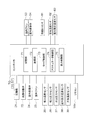
- the whole block diagram of an air conditioning apparatus The block diagram which showed typically the schematic structure of the controller, and each part connected to a controller.
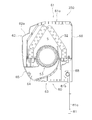
- the side view sectional drawing of the indoor unit which concerns on the modification B.
- FIG. The side view sectional drawing of the indoor unit which concerns on the modification D.
- FIG. The block diagram which showed typically the schematic structure of the controller of the air conditioning apparatus which concerns on the modification D, and each part connected to a controller.
- the indoor unit 50 of the air conditioner 100 that is an indoor unit of the refrigeration apparatus according to the embodiment will be described with reference to the drawings.
- the following embodiments are specific examples, do not limit the disclosure, and can be modified as appropriate without departing from the scope of the disclosure.
- FIG. 1 is a schematic configuration diagram of an air conditioner 100 according to an embodiment.
- the air conditioning apparatus 100 is an apparatus that harmonizes air in a target space by performing a vapor compression refrigeration cycle.
- the air conditioner 100 mainly includes an outdoor unit 2, an indoor unit 50, a liquid refrigerant communication tube 6 and a gas refrigerant communication tube 7 that connect the outdoor unit 2 and the indoor unit 50, and a plurality of input devices and output devices.
- a remote controller 50 a and a controller 70 that controls the operation of the air conditioner 100 are provided.
- a refrigerant cycle in which the refrigerant sealed in the refrigerant circuit 10 is compressed, cooled or condensed, depressurized, heated or evaporated, and then compressed again is performed.
- the refrigerant circuit 10 is filled with R32 as a refrigerant for performing a vapor compression refrigeration cycle.
- Outdoor unit 2 The outdoor unit 2 is connected to the indoor unit 50 via the liquid refrigerant communication pipe 6 and the gas refrigerant communication pipe 7 and constitutes a part of the refrigerant circuit 10.
- the outdoor unit 2 mainly includes a compressor 21, a four-way switching valve 22, an outdoor heat exchanger 23, an outdoor expansion valve 24, an outdoor fan 25, a liquid side closing valve 29, and a gas side closing valve 30. ,have.
- the outdoor unit 2 includes a discharge pipe 31, a suction pipe 34, an outdoor gas side pipe 33, and an outdoor liquid side pipe 32 that are pipes constituting the refrigerant circuit 10.
- the discharge pipe 31 connects the discharge side of the compressor 21 and the first connection port of the four-way switching valve 22.
- the suction pipe 34 connects the suction side of the compressor 21 and the second connection port of the four-way switching valve 22.
- the outdoor gas side pipe 33 connects the third port of the four-way switching valve 22 and the gas side closing valve 30.
- the outdoor liquid side pipe 32 extends from the fourth port of the four-way switching valve 22 to the liquid side closing valve 29 via the outdoor heat exchanger 23 and the outdoor expansion valve 24.
- the compressor 21 is a device that compresses the low-pressure refrigerant in the refrigeration cycle until it reaches a high pressure.
- a compressor having a hermetic structure in which a rotary type or scroll type positive displacement compression element (not shown) is rotationally driven by a compressor motor M21 is used as the compressor 21 .
- the compressor motor M21 is for changing the capacity, and the operation frequency can be controlled by an inverter.
- the four-way switching valve 22 switches the connection state, thereby connecting the discharge side of the compressor 21 and the outdoor heat exchanger 23 while connecting the suction side of the compressor 21 and the gas side shut-off valve 30. It is possible to switch between the state and the heating operation connection state in which the suction side of the compressor 21 and the outdoor heat exchanger 23 are connected while the discharge side of the compressor 21 and the gas side shut-off valve 30 are connected.
- the outdoor heat exchanger 23 is a heat exchanger that functions as a high-pressure refrigerant radiator in the refrigeration cycle during the cooling operation, and functions as a low-pressure refrigerant evaporator in the refrigeration cycle during the heating operation.
- the outdoor fan 25 sucks outdoor air into the outdoor unit 2, causes heat exchange with the refrigerant in the outdoor heat exchanger 23, and then generates an air flow to be discharged outside.
- the outdoor fan 25 is rotationally driven by an outdoor fan motor M25.
- the outdoor expansion valve 24 is an electric expansion valve capable of controlling the valve opening degree, and is provided between the outdoor heat exchanger 23 and the liquid side closing valve 29 in the middle of the outdoor liquid side piping 32.
- the liquid side shut-off valve 29 is a manual valve disposed at a connection portion between the outdoor liquid side pipe 32 and the liquid refrigerant communication pipe 6.
- the gas side shut-off valve 30 is a manual valve disposed at a connection portion between the outdoor gas side pipe 33 and the gas refrigerant communication pipe 7.
- the outdoor unit 2 is provided with various sensors.
- a suction temperature sensor 35 that is a refrigerant temperature on the suction side of the compressor 21 and a suction pressure that is a refrigerant pressure on the suction side of the compressor 21 are detected.
- a discharge pressure sensor 37 that detects a discharge pressure that is a pressure of the refrigerant on the discharge side of the compressor 21.
- the outdoor heat exchanger 23 is provided with an outdoor heat exchange temperature sensor 38 that detects the temperature of the refrigerant flowing through the outdoor heat exchanger 23.
- an outdoor temperature sensor 39 for detecting the temperature of the outdoor air sucked into the outdoor unit 2 is disposed around the outdoor heat exchanger 23 or the outdoor fan 25.
- the outdoor unit 2 has an outdoor unit control unit 20 that controls the operation of each unit constituting the outdoor unit 2.
- the outdoor unit control unit 20 has a microcomputer including a CPU, a memory, and the like.
- the outdoor unit controller 20 is connected to the indoor unit controller 57 of each indoor unit 50 via a communication line, and transmits and receives control signals and the like.
- the outdoor unit controller 20 is electrically connected to an intake temperature sensor 35, an intake pressure sensor 36, a discharge pressure sensor 37, an outdoor heat exchange temperature sensor 38, and an outdoor air temperature sensor 39, and signals from the sensors. Receive.
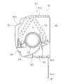
- (1-2) Indoor unit 50 As shown in FIG. 3, the indoor unit 50 is installed on the wall surface of the room R that is the target space.
- the indoor unit 50 is connected to the outdoor unit 2 via the liquid refrigerant communication tube 6 and the gas refrigerant communication tube 7 and constitutes a part of the refrigerant circuit 10.
- the indoor unit 50 includes an indoor expansion valve 54, an indoor heat exchanger 52, an indoor fan 53, a casing 60, and the like.
- the indoor unit 50 includes an indoor liquid refrigerant pipe 58 that connects the liquid side end of the indoor heat exchanger 52 and the liquid refrigerant communication pipe 6, and a gas side end of the indoor heat exchanger 52 and the gas refrigerant communication pipe 7. And an indoor gas refrigerant pipe 59 to be connected.
- the indoor expansion valve 54 is an electric expansion valve capable of controlling the valve opening, and is provided in the middle of the indoor liquid refrigerant pipe 58.
- the indoor heat exchanger 52 is a heat exchanger that functions as a low-pressure refrigerant evaporator in the refrigeration cycle during cooling operation and functions as a high-pressure refrigerant radiator in the refrigeration cycle during heating operation.
- the indoor fan 53 sucks indoor air into the casing 60 of the indoor unit 50, causes the indoor heat exchanger 52 to exchange heat with the refrigerant, and then generates an air flow to be discharged outside.
- the indoor fan 53 is rotationally driven by an indoor fan motor M53.
- the indoor unit 50 is provided with various sensors.
- an air temperature sensor 82 that detects an air temperature in a space in which the indoor unit 50 is installed, and an indoor that detects the temperature of the refrigerant flowing through the indoor heat exchanger 52.
- a heat exchanger temperature sensor 83 is disposed inside the casing 60 of the indoor unit 50.
- a refrigerant gas sensor 81 (for example, according to the refrigerant gas concentration) for detecting the concentration of the leaked refrigerant when the refrigerant gas sealed in the refrigerant circuit 10 leaks outside the casing 60 of the indoor unit 50. Sensors with different electrical responses).
- the refrigerant gas sensor 81 is connected to the indoor unit controller 57 via the communication line 81a, and is positioned below the bottom surface 63 of the casing 60 of the indoor unit 50, as will be described later.
- the indoor unit 50 has an indoor unit control unit 57 that controls the operation of each part constituting the indoor unit 50.
- the indoor unit control unit 57 has a microcomputer including a CPU, a memory, and the like.
- the indoor unit controller 57 is connected to the outdoor unit controller 20 via a communication line, and transmits and receives control signals and the like.
- the indoor unit controller 57 is electrically connected to the refrigerant gas sensor 81, the air temperature sensor 82, and the indoor heat exchanger temperature sensor 83, and receives signals from the sensors.
- the casing 60 is a substantially rectangular parallelepiped housing that houses the indoor heat exchanger 52, the indoor fan 53, the indoor expansion valve 54, the various sensors 82 and 83, and the indoor unit control unit 57 inside. As shown in FIGS. 3 and 4, the casing 60 accommodates the indoor heat exchanger 52 therein so that the indoor heat exchanger 52 has a substantially inverted V-shaped cross-sectional view in a side view, and is a cross-flow fan.
- the fan 53 is housed inside so that the left-right direction is the axial direction.
- the casing 60 includes a top surface 61 constituting the upper end portion of the casing 60, a front panel 62 constituting the front portion of the casing 60, a bottom surface 63 constituting the bottom portion of the casing 60, and an outlet. 64, louver 65, left and right side surfaces (not shown), and the like.
- the casing 60 is fixed to the wall surface of the room R via an installation plate 66 provided on the back side.
- the top surface 61 is provided with a plurality of top surface suction ports 61a opened in the vertical direction.
- the front panel 62 is a panel that extends downward from the vicinity of the front end of the top surface 61.
- the front panel 62 is provided with a front suction port 62a having an elongated opening on the left and right in the upper portion.
- the air in the room R is taken into the ventilation path S composed of a space in which the indoor heat exchanger 52 and the indoor fan 53 in the casing 60 are housed through the top surface suction port 61a and the front surface suction port 62a.
- the bottom surface 63 extends substantially horizontally below the indoor heat exchanger 52 and the indoor fan 53.
- the bottom surface 63 is provided with an opening 63a for allowing a communication line 81a connecting the refrigerant gas sensor 81 and the indoor unit control unit 57 to pass in the vertical direction.
- the blower outlet 64 opens to the front lower side in the lower front side of the casing 60, which is below the front panel 62 and in front of the bottom surface 63.
- This blower outlet 64 consists of an elongate opening in the left-right direction.
- the blower outlet 64 communicates with the top surface suction port 61a and the front surface suction port 62a through a ventilation path S formed of a space in which the indoor heat exchanger 52 and the indoor fan 53 are accommodated.
- the air in the air-conditioned room sucked from the top surface suction port 61a and the front surface suction port 62a is introduced into the ventilation path S, passes through the indoor heat exchanger 52, is then pressurized by the indoor fan 53, and blown.
- the air is blown out into the air-conditioned room through the outlet 64.
- the blower outlet 64 is provided with a louver 65 for changing the direction of air blown into the air-conditioned room.
- the above-mentioned refrigerant gas sensor 81 is disposed so as not to directly touch the conditioned air F flowing through the ventilation path S and the outlet 64 in the casing 60 as shown in FIG. That is, the air conditioned by the indoor unit 50 flows toward the front lower side through the air outlet 64 of the casing 60, but the refrigerant gas sensor 81 is fixed at a position outside the region where the conditioned air F flows. Yes.
- the refrigerant gas sensor 81 is provided so as to be located in a range of 30 mm or more and 300 mm or less below the bottom surface 63 of the casing 60, and is fixed to a side surface of the room R.
- the remote controller 50a is an input device for a user of the indoor unit 50 to input various instructions for switching the operating state of the air conditioning apparatus 100.
- the remote controller 50a also functions as an output device for performing an operation state of the air conditioner 100 and a predetermined notification.
- the remote controller 50a is connected to the indoor unit controller 57 via a communication line, and transmits / receives signals to / from each other.
- the remote controller 50a has a built-in speaker.
- Controller 70 In the air conditioner 100, the outdoor unit controller 20 and the indoor unit controller 57 are connected via a communication line, whereby the controller 70 that controls the operation of the air conditioner 100 is configured. ing.
- FIG. 2 is a block diagram schematically showing a schematic configuration of the controller 70 and each unit connected to the controller 70. As shown in FIG.
- the controller 70 has a plurality of control modes, and controls the operation of the air conditioning apparatus 100 according to the control modes.
- the controller 70 has, as control modes, a normal operation mode that is executed during normal times and a refrigerant leakage control mode that is executed when refrigerant leakage occurs.
- the controller 70 includes actuators (specifically, the compressor 21 (compressor motor M21), the outdoor expansion valve 24, and the outdoor fan 25 (outdoor fan motor M25)) included in the outdoor unit 2, and various sensors (suction).
- the temperature sensor 35, the suction pressure sensor 36, the discharge pressure sensor 37, the outdoor heat exchange temperature sensor 38, the outdoor air temperature sensor 39, etc.) are electrically connected.
- the controller 70 is electrically connected to actuators included in the indoor unit 50 (specifically, the indoor fan 53 (indoor fan motor M53) and the indoor expansion valve 54).
- the controller 70 is electrically connected to the refrigerant gas sensor 81, the air temperature sensor 82, the indoor heat exchanger temperature sensor 83, and the remote controller 50a.
- the refrigerant gas sensor 81 is connected to the controller 70 by being connected to the indoor unit controller 57 via the communication line 81a.
- the controller 70 mainly includes a storage unit 71, a communication unit 72, a mode control unit 73, an actuator control unit 74, and an output control unit 75. These units in the controller 70 are realized by the units included in the outdoor unit control unit 20 and / or the indoor unit control unit 57 functioning integrally.
- the storage unit 71 includes, for example, a ROM, a RAM, and a flash memory, and includes a volatile storage area and a nonvolatile storage area.
- the storage unit 71 stores a control program that defines processing in each unit of the controller 70.
- the storage unit 71 stores, as appropriate, predetermined information (for example, a detection value of each sensor, a command input to the remote controller 50a, and the like) by each unit of the controller 70 in a predetermined storage area.
- the communication unit 72 is a functional unit that plays a role as a communication interface for transmitting and receiving signals to and from each device connected to the controller 70.
- the communication unit 72 receives a request from the actuator control unit 74 and transmits a predetermined signal to the designated actuator. Further, the communication unit 72 receives signals output from the various sensors 35 to 39, 81 to 83, and the remote controller 50a and stores them in a predetermined storage area of the storage unit 71.
- the mode control unit 73 is a functional unit that performs control mode switching and the like.
- the mode control unit 73 sets the control mode to the normal operation mode when none of the indoor units 50 satisfies the predetermined refrigerant leakage condition.
- the mode control unit 73 switches the control mode to the refrigerant leakage control mode.
- Actuator controller 74 The actuator control unit 74 controls the operation of each actuator (for example, the compressor 21) included in the air conditioning apparatus 100 according to the situation according to the control program.
- the actuator controller 74 determines the rotational speed of the compressor 21, the rotational speed of the outdoor fan 25, the indoor fan 53, and the valve of the outdoor expansion valve 24 according to the set temperature, detection values of various sensors, and the like.
- the opening degree, the opening degree of the indoor expansion valve 54, and the like are controlled in real time.
- the actuator control unit 74 controls the operation of each actuator so that a predetermined operation is performed in the refrigerant leakage control mode. Specifically, the actuator control unit 74 stops the supply of the refrigerant to the indoor unit 50 when the refrigerant leaks.
- Output control unit 75 is a functional unit that controls the operation of the remote controller 50a as a display device.
- the output control unit 75 causes the remote controller 50a to output predetermined information in order to display information related to the driving state and situation to the administrator.
- the output control unit 75 displays various information such as the set temperature on the remote controller 50a during the cooling operation mode in the normal operation mode.
- the output control unit 75 displays information indicating that a refrigerant leak has occurred on the display of the remote controller 50a in the refrigerant leak control mode. Further, the output control unit 75 informs by voice that the refrigerant has leaked through a speaker built in the remote controller 50a. Further, the output control unit 75 causes the remote controller 50a to display information for prompting notification to the service engineer.
- a cooling operation mode and a heating operation mode are provided.
- the controller 70 determines and executes the cooling operation mode or the heating operation mode based on the instruction received from the remote controller 50a or the like.
- connection state of the four-way switching valve 22 is set to the suction of the compressor 21 while the discharge side of the compressor 21 and the outdoor heat exchanger 23 are connected.
- a cooling operation connected state in which the gas side closing valve 30 is connected to the refrigerant circuit 10, and the refrigerant charged in the refrigerant circuit 10 mainly includes the compressor 21, the outdoor heat exchanger 23, the outdoor expansion valve 24, the indoor expansion valve 54, The indoor heat exchanger 52 is circulated in this order.
- the refrigerant is discharged into the refrigerant circuit 10 after being sucked into the compressor 21 and compressed.
- the low pressure in the refrigeration cycle is the suction pressure detected by the suction pressure sensor 36
- the high pressure in the refrigeration cycle is the discharge pressure detected by the discharge pressure sensor 37.
- the compressor 21 performs capacity control according to the cooling load required by the indoor unit 50. Specifically, the target value of the suction pressure is set according to the cooling load required by the indoor unit 50, and the operating frequency of the compressor 21 is controlled so that the suction pressure becomes the target value.
- the gas refrigerant discharged from the compressor 21 flows into the gas side end of the outdoor heat exchanger 23 through the discharge pipe 31 and the four-way switching valve 22.
- the gas refrigerant that has flowed into the gas side end of the outdoor heat exchanger 23 performs heat exchange with the outdoor air supplied by the outdoor fan 25 in the outdoor heat exchanger 23 to dissipate and condense, and becomes a liquid refrigerant. It flows out from the liquid side end of the outdoor heat exchanger 23.
- the liquid refrigerant flowing out from the liquid side end of the outdoor heat exchanger 23 flows into the indoor unit 50 via the outdoor liquid side pipe 32, the outdoor expansion valve 24, the liquid side closing valve 29, and the liquid refrigerant communication pipe 6.
- the outdoor expansion valve 24 is controlled to be fully opened.
- the refrigerant flowing into the indoor unit 50 flows into the indoor expansion valve 54 through a part of the indoor liquid refrigerant pipe 58.
- the refrigerant that has flowed into the indoor expansion valve 54 is depressurized by the indoor expansion valve 54 to a low pressure in the refrigeration cycle, and then flows into the liquid side end of the indoor heat exchanger 52.
- the opening degree of the indoor expansion valve 54 is controlled so that the superheat degree of the refrigerant sucked in the compressor 21 becomes a predetermined superheat degree in the cooling operation mode.
- the superheat degree of the refrigerant sucked by the compressor 21 is calculated by the controller 70 using the temperature detected by the suction temperature sensor 35 and the pressure detected by the suction pressure sensor 36.
- the refrigerant flowing into the liquid side end of the indoor heat exchanger 52 evaporates by exchanging heat with the indoor air supplied by the indoor fan 53 in the indoor heat exchanger 52 to become a gas refrigerant. It flows out from the gas side end.
- the gas refrigerant flowing out from the gas side end of the indoor heat exchanger 52 flows into the gas refrigerant communication pipe 7 through the indoor gas refrigerant pipe 59.
- (3-2) Heating Operation Mode In the air conditioning apparatus 100, in the heating operation mode, the connection state of the four-way switching valve 22 is set to the suction of the compressor 21 while the discharge side of the compressor 21 and the gas side shut-off valve 30 are connected.
- the refrigerant and the refrigerant charged in the refrigerant circuit 10 mainly include the compressor 21, the indoor heat exchanger 52, the indoor expansion valve 54, the outdoor expansion valve 24, The outdoor heat exchanger 23 is circulated in this order.
- the refrigerant is discharged into the refrigerant circuit 10 after being sucked into the compressor 21 and compressed.
- the low pressure in the refrigeration cycle is the suction pressure detected by the suction pressure sensor 36
- the high pressure in the refrigeration cycle is the discharge pressure detected by the discharge pressure sensor 37.
- the compressor 21 performs capacity control according to the heating load required by the indoor unit 50. Specifically, the target value of the discharge pressure is set according to the heating load required by the indoor unit 50, and the operation frequency of the compressor 21 is controlled so that the discharge pressure becomes the target value.
- the gas refrigerant discharged from the compressor 21 flows through the discharge pipe 31, the four-way switching valve 22, the outdoor gas side pipe 33, and the gas refrigerant communication pipe 7, and then flows into the indoor unit 50 through the indoor gas refrigerant pipe 59. To do.
- the refrigerant flowing into the indoor unit 50 flows into the gas side end of the indoor heat exchanger 52 via the indoor gas refrigerant pipe 59.
- the refrigerant flowing into the gas side end of the indoor heat exchanger 52 exchanges heat with the indoor air supplied by the indoor fan 53 in the indoor heat exchanger 52 to dissipate and condense, and becomes a liquid refrigerant. It flows out from the liquid side end of the exchanger 52.
- the refrigerant flowing out from the liquid side end of the indoor heat exchanger 52 flows into the liquid refrigerant communication pipe 6 via the indoor liquid refrigerant pipe 58 and the indoor expansion valve 54. Note that the opening degree of the indoor expansion valve 54 is controlled so as to be fully opened in the heating operation mode.
- the refrigerant flowing through the liquid refrigerant communication pipe 6 flows into the outdoor expansion valve 24 via the liquid side closing valve 29 and the outdoor liquid side pipe 32.
- the refrigerant that has flowed into the outdoor expansion valve 24 is depressurized to a low pressure in the refrigeration cycle, and then flows into the liquid side end of the outdoor heat exchanger 23.
- the valve opening degree of the outdoor expansion valve 24 is controlled so that the superheat degree of the refrigerant sucked in the compressor 21 becomes a predetermined superheat degree in the heating operation mode.
- the refrigerant flowing in from the liquid side end of the outdoor heat exchanger 23 evaporates by exchanging heat with the outdoor air supplied by the outdoor fan 25 in the outdoor heat exchanger 23 to become a gas refrigerant. It flows out from the gas side end.
- the refrigerant flowing out from the gas side end of the outdoor heat exchanger 23 is again sucked into the compressor 21 through the four-way switching valve 22 and the suction pipe 34.
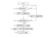
- step S10 when the normal operation mode of the cooling operation mode or the heating operation mode is being executed, the controller 70 determines whether or not a predetermined period has elapsed since the start of the cooling or heating operation or the latest leakage refrigerant gas concentration detection. Determine whether. If it is determined that the predetermined period has elapsed, the process proceeds to step S11. If it is determined that the predetermined period has not elapsed, step S10 is repeated.
- step S11 the controller 70 temporarily stops the driving of the indoor fan 53 and reduces the air flow in the room R.
- step S12 the controller 70 determines whether or not the detected refrigerant concentration in the refrigerant gas sensor 81 is equal to or higher than a predetermined refrigerant concentration.
- the predetermined refrigerant concentration is determined in advance according to the type of refrigerant (R32 in the present embodiment) sealed in the refrigerant circuit 10, and is stored in the storage unit 71.
- the controller 70 determines that the refrigerant concentration detected by the refrigerant gas sensor 81 is equal to or higher than the predetermined refrigerant concentration, the process proceeds to step S14.
- the refrigerant concentration detected by the refrigerant gas sensor 81 is less than the predetermined refrigerant concentration, the process proceeds to step S13.
- step S13 the controller 70 resumes the driving of the stopped indoor fan 53, and returns to step S10 while continuing the normal operation mode.
- step S14 the controller 70 starts the refrigerant leakage control mode, and causes the output control unit 75 to display information indicating that the refrigerant has leaked as character information on the display of the remote controller 50a.
- the controller 70 causes the output control unit 75 to notify that the refrigerant has leaked from the speaker of the remote controller 50a as audio information.
- step S15 the controller 70 controls the forced operation state so that the rotation speed of the indoor fan 53 is maximized. Thereby, it is possible to stir the leaked refrigerant medium and to prevent the concentration from increasing locally.
- step S16 the pump down operation is performed.
- the outdoor expansion valve 24 is closed and the compressor 21 is driven and the outdoor fan 25 is driven while the connection state of the four-way switching valve 22 is set to the connection state of the cooling operation mode. 23 is caused to function as a refrigerant condenser.
- the refrigerant present on the indoor unit 50 side in the refrigerant circuit 10 is collected from the discharge side of the compressor 21 of the outdoor unit 2 to the outdoor expansion valve 24 via the outdoor heat exchanger 23. Further, the leakage of the refrigerant from the leakage portion in the indoor unit 50 is suppressed.
- the pump-down operation is performed while the connection state of the four-way switching valve 22 is maintained.
- the heating operation mode is executed when the refrigerant leaks
- the four-way switching valve 22 is switched to the connection state in the cooling operation mode and the pump-down operation is performed.
- the pump-down operation is terminated when the pressure detected by the suction pressure sensor 36 is equal to or lower than a predetermined end pressure, the drive of the compressor 21 is stopped, and the operation of the air conditioner 100 is stopped.
- the refrigerant gas sensor 81 is provided at a position outside the region where the conditioned air F flows. For this reason, since it can suppress that the refrigerant gas sensor 81 touches the flow of conditioned air directly, it can suppress that dew condensation arises in refrigerant gas sensor 81 itself. Thereby, the detection accuracy in the refrigerant gas sensor 81 can be increased.
- the refrigerant gas sensor 81 is disposed in a region below the bottom surface 63 of the casing 60 of the indoor unit 50, and the driving of the indoor fan 53 is stopped even when the normal operation mode is being executed. In this state, the refrigerant gas sensor 81 performs detection while keeping the air flow in the room R small.
- the refrigerant circuit 10 of the air conditioner 100 is filled without being guided by the flow F of the conditioned air.
- R32 which is a refrigerant having a specific gravity greater than that of air, tends to gather in the lower region of the indoor unit 5 rather than the upper portion due to its own weight when leaking.
- the refrigerant gas sensor 81 is provided in the area
- the leakage in the indoor unit 50 is performed because the outdoor unit 2 collects the refrigerant by performing a pump-down operation. It is possible to suppress further leakage of the refrigerant from the location.
- the indoor fan 53 is forcibly driven at the maximum number of revolutions, so that the refrigerant concentration is locally increased indoors. It is possible to suppress the occurrence of an increasing part.
- the refrigerant sealed in the refrigerant circuit 10 is not limited to this.
- a refrigerant other than R32 a flammable refrigerant having the refrigerant safety classification standard of ASHRAE 34 classified as A3, ASHRAE 34, Low-flammability refrigerant classified as A2 in the refrigerant safety classification standard, slightly flammable refrigerant classified as A2L in the safety classification of ASHRAE34, and strong toxicity classified as B in the refrigerant safety classification standard of ASHRAE34 A refrigerant may be used.
- a refrigerant having a lower GWP than R32 (a natural refrigerant such as R717, R170, R1270, R290, R600, R600a, R152a, or a mixed refrigerant thereof) is used. May be.
- the controller 70 determines the detection signal from the refrigerant gas sensor 81 so that the leakage of the refrigerant can be detected even when the operation is stopped. Also good.
- the air flow in the room R can be kept small as in the case of the temporary stop of the indoor fan 53 during execution of the normal operation mode of the above embodiment, so that detection can be performed with high accuracy. .
- a sensor lifting mechanism 88 may be provided so that the refrigerant gas sensor 81 can be moved in the vertical direction.
- the sensor elevating mechanism 88 is electrically connected to the indoor unit controller 57 and is driven and controlled by the actuator controller 74 of the controller 70 with the configuration shown in FIG. Specifically, when raising the descending refrigerant gas sensor 81, the sensor elevating mechanism 88 is driven to wind up the communication line 81a, and the refrigerant gas sensor 81 is accommodated in a storage position 81b provided on the bottom surface 63. Raise to. Further, the sensor elevating mechanism 88 is driven so as to loosen the communication line 81a when lowering the refrigerant gas sensor 81 accommodated in the storage position 81b. Lower to the position.
- the processing when the refrigerant gas sensor 81 is moved up and down is the same as in the above embodiment, and as shown in FIG. 9, the step of lowering the refrigerant gas sensor 81 between steps S11 and S12 in the above embodiment.
- step S11x and further executing step S12x for raising the refrigerant gas sensor 81 between steps S12 and S13 the same effect as in the above embodiment can be obtained.
- the refrigerant gas sensor 81 can be accommodated, the appearance can be refreshed.
- the notification mode is not limited to this.
- the lamp when a lamp is provided in the remote controller 50a, the lamp may be turned on or blinked.
- the light emission state when it is determined that the refrigerant is in a normal state where the refrigerant has not leaked and the light emission state when it is determined that the refrigerant has leaked are determined.
- Notification may be performed in a different manner by changing the flashing speed or the like.
- the controller 70 when the controller 70 is communicably connected to an external remote monitoring device configured by a computer via the communication unit 72 via a communication network, the external remote monitoring device or the like is Information indicating that the refrigerant has leaked may be transmitted. In this case, it becomes possible for the service engineer who is familiar with the countermeasure for the refrigerant leakage monitored by the remote monitoring device to appropriately grasp the situation.
- control of the air conditioner 100 in the refrigerant leakage control mode is not limited to this.
- the control of reducing the frequency of the compressor 21 may be performed.
- the situation in which further refrigerant is supplied to the indoor heat exchanger 52 may be avoided by closing the indoor expansion valve 54.
- the indoor fan 53 when forcibly operating the fan, the fan provided in the ventilation facility may be forcibly operated at the same time.
Landscapes
- Engineering & Computer Science (AREA)
- Mechanical Engineering (AREA)
- General Engineering & Computer Science (AREA)
- Chemical & Material Sciences (AREA)
- Combustion & Propulsion (AREA)
- Physics & Mathematics (AREA)
- Thermal Sciences (AREA)
- Air Conditioning Control Device (AREA)
- Air Filters, Heat-Exchange Apparatuses, And Housings Of Air-Conditioning Units (AREA)
Abstract
冷媒ガスセンサにおける結露を抑制しつつ、冷媒漏洩を検出することが可能な冷凍装置の室内ユニットを提供する。冷媒回路(10)を有する空気調和装置(100)の室内ユニット(50)であって、ケーシング(60)と、室内ファン(53)と、冷媒ガスセンサ(81)と、を備えている。冷媒回路(10)は、冷媒が封入されており、冷凍サイクルを行う。ケーシング(60)は、冷媒回路(10)の少なくとも一部を内部に収容しており、上下方向以外の方向に開口した吹出口(64)を有している。室内ファン(53)は、ケーシング(60)の内部に収容されており、吹出口(64)からケーシング(60)の外部に向かう空気流れ(F)を生じさせる。冷媒ガスセンサ(81)は、ケーシング(60)の底面(63)の下方において冷媒ガスを検出可能である。
Description
本開示は、冷凍装置の室内ユニットに関する。
昨今、地球温暖化を抑制するために、冷凍装置において環境への影響が少ない冷媒を採用することが求められている。ここで、従来より広く用いられているHFC(ハイドロフルオロカーボン)冷媒よりも環境への影響が少ない冷媒としては、GWP(地球温暖化係数)の低い冷媒が挙げられる。
しかし、GWPの低い冷媒は、燃焼性を伴うものが多い。
これに対して、冷凍装置から冷媒が漏洩した場合に備えて、冷媒の漏洩を検出可能とする技術が考案されている。例えば、特許文献1(特開2016-90109号公報)では、空気よりも比重の大きな冷媒の漏洩を検出するために、床置きの室内機においてドレンパンと同じ高さまたはドレンパンの下方で奥行きはドレンパンと異なる位置に冷媒ガスセンサを設けることが提案されている。
上記特許文献1に記載の床置き型の室内ユニットとは異なり、例えば、壁掛け型等の室内ユニットでは、送風を行わない停止時に冷媒の漏洩が生じると、壁掛け型の場合には床面付近に設けられているわけではないため、室内ユニットの内部の熱交換器の下方周辺において漏洩冷媒が溜まるのではなく、漏洩冷媒は室内ユニットの外部に漏れ出して室内空間のうちの下方の領域に達してしまう。ここで、熱交換器の下方における吹出用の送風経路の途中に冷媒ガスセンサを設けようとすると、駆動時に空気流れが生じる箇所に冷媒ガスセンサが位置することとなり、冷媒ガスセンサに結露が生じてしまうおそれがある。
本開示は、上述した点に鑑みてなされたものであり、本開示の課題は、冷媒ガスセンサにおける結露を抑制しつつ、冷媒漏洩を検出することが可能な冷凍装置の室内ユニットを提供することにある。
第1観点に係る冷凍装置の室内ユニットは、冷媒回路を有する冷凍装置の室内ユニットであって、ケーシングと、送風ファンと、冷媒ガスセンサと、を備えている。冷媒回路は、冷媒が封入されており、冷凍サイクルを行う。ケーシングは、冷媒回路の少なくとも一部を内部に収容しており、上下方向以外の方向に開口した吹出口を有している。送風ファンは、ケーシングの内部に収容されており、吹出口からケーシングの外部に向かう空気流れを生じさせる。冷媒ガスセンサは、ケーシングの下面の下方、もしくは、ケーシングの上面の上方において冷媒ガスを検出可能である。
なお、冷凍装置は、2つの空間にわたって配置されていてもよい。例えば、冷凍装置は、室内に設置された室内ユニットと、室外に設置された室外ユニットとを有して構成されていてもよい。また、例えば、冷凍装置は、室内に向いた部分と室外に向いた部分とが1つのケーシングによって一体化された構成であってもよい。
この冷凍装置の室内ユニットでは、空気よりも比重が大きな冷媒が用いられている場合には冷媒ガスセンサによってケーシングの下面の下方における冷媒ガスの検出を行うようにし、空気よりも比重が小さな冷媒が用いられている場合には冷媒ガスセンサによってケーシングの上面の上方において冷媒ガスの検出を行うようにすることで、冷媒漏洩を検出することが可能になる。しかも、冷媒ガスセンサは、ケーシングの下面の下方もしくはケーシングの上面の上方において冷媒ガスを検出するものであるため、上下方向以外の方向に開口したケーシングの吹出口からケーシングの外部に向かう空気流れが触れにくい。このため、冷媒ガスセンサに調和空気が触れることで冷媒ガスセンサに生じる結露を抑制することが可能になっている。以上によって、冷媒ガスセンサにおける結露を抑制しつつ、冷媒漏洩を検出することが可能になる。
第2観点に係る冷凍装置の室内ユニットは、第1観点に係る冷凍装置の室内ユニットであって、冷媒回路に封入されている冷媒は、可燃性冷媒、弱燃性冷媒、微燃性冷媒、強毒性冷媒のいずれか1つの単体冷媒もしくは混合冷媒である。
ここで、可燃性冷媒としては、ASHRAE34の冷媒安全性分類規格のA3に分類される冷媒が挙げられる。また、弱燃性冷媒としては、ASHRAE34の冷媒安全性分類規格のA2に分類される冷媒が挙げられる。さらに、微燃性冷媒としては、ASHRAE34の冷媒安全性分類規格のA2Lに分類される冷媒が挙げられる。また、強毒性冷媒としては、ASHRAE34の冷媒安全性分類規格のBに分類される冷媒が挙げられる。
この冷凍装置の室内ユニットでは、漏洩時に燃焼可能性や人体へ危害を及ぼす可能性のある冷媒が冷媒回路に用いられている場合であっても、冷媒ガスセンサにおける結露を抑制しつつ、冷媒漏洩を検出することが可能になる。
第3観点に係る冷凍装置の室内ユニットは、第1観点に係る冷凍装置の室内ユニットであって、冷媒回路に封入されている冷媒は、R32、または、R32よりもGWPの低い冷媒である。
ここで、R32よりもGWPの低い冷媒としては、R717等の自然冷媒、R170、R1270、R290、R600、R600a、R152aまたはこれらの混合冷媒等が挙げられる。
この冷凍装置の室内ユニットでは、GWP(地球温暖化係数)が低い冷媒が冷媒回路に用いられている場合であっても、冷媒ガスセンサにおける結露を抑制しつつ、冷媒漏洩を検出することが可能になる。
第4観点に係る冷凍装置の室内ユニットは、第1観点から第3観点のいずれかに係る冷凍装置の室内ユニットであって、冷媒ガスセンサは、ケーシングの下面から下方に30mm以上300mm以下の範囲で冷媒ガスの検出を行う。冷凍装置の室内ユニットは、ケーシングが室内の壁面に固定された状態で用いられる。
この冷凍装置の室内ユニットでは、ケーシングが室内の壁面に固定されることにより、ケーシングが床面から上方に離れた位置に固定された状態で用いられる。そして、この冷凍装置において空気よりも比重が大きな冷媒が用いられている場合には、漏洩した冷媒は、室内ユニットのケーシングの下面よりも下方の領域において可燃域を形成することを見出した。これに対して、この冷凍装置の室内ユニットでは、冷媒ガスセンサが、ケーシングの下面から下方に30mm以上300mm以下の範囲で冷媒ガスの検出を行う。このため、空気よりも比重が大きな冷媒が用いられている場合における冷媒の漏洩を正確に検出することが可能になる。
第5観点に係る冷凍装置の室内ユニットは、第4観点に係る冷凍装置の室内ユニットであって、冷媒ガスセンサは、ケーシングの下面から下方に30mm以上300mm以下の範囲に固定されている。
この冷凍装置の室内ユニットでは、冷媒ガスセンサは、ケーシングの下面から下方に30mm以上300mm以下の範囲に固定されているため、ケーシングの下面よりも下方の領域における冷媒を常時検出することが可能になる。
第6観点に係る冷凍装置の室内ユニットは、第4観点に係る冷凍装置の室内ユニットであって、制御部をさらに備えている。制御部は、送風ファンの駆動を停止させた状態で、冷媒ガスセンサによる冷媒ガスの検出を行う。
この冷凍装置の室内ユニットでは、送風ファンの駆動が停止している状態では、漏洩した冷媒は、ケーシングの吹出口から吹き出されにくく、特に、ケーシングの下面の下方に溜まりがちになる。これに対して、この冷凍装置の室内ユニットでは、制御部は、送風ファンの駆動を停止させた状態で、特に冷媒が滞留しがちな箇所を冷媒ガスセンサによって検出するため、空気よりも比重が大きな冷媒が用いられている場合における冷媒の漏洩を正確に検出することが可能になる。
第7観点に係る冷凍装置の室内ユニットは、第6観点に係る冷凍装置の室内ユニットであって、昇降機構をさらに備えている。昇降機構は、冷媒ガスセンサをケーシングの下面から下方向けて出し入れするための機構である。制御部は、送風ファンの駆動を停止させた状態で昇降機構を用いてケーシングの下面から下方に30mm以上300mm以下の位置まで冷媒ガスセンサを下降させて冷媒ガスセンサに冷媒ガスを検出させる。
この冷凍装置の室内ユニットでは、送風ファンの駆動が停止している状態では、漏洩した冷媒は、ケーシングの吹出口を超えにくく、特に、ケーシングの下面の下方に溜まりがちになる。これに対して、この冷凍装置の室内ユニットでは、制御部は、送風ファンの駆動を停止させた状態で昇降機構を用いてケーシングの下面から下方に30mm以上300mm以下の位置まで冷媒ガスセンサを下降させて、特に冷媒が滞留しがちな箇所に冷媒ガスセンサを移動させることで、空気よりも比重が大きな冷媒が用いられている場合における冷媒の漏洩を正確に検出することが可能になる。
以下、図面を参照しながら、一実施形態に係る冷凍装置の室内ユニットである空気調和装置100の室内ユニット50について説明する。なお、以下の実施形態は、具体例であって、開示内容を限定するものではなく、開示の要旨を逸脱しない範囲で適宜変更が可能である。
(1)空気調和装置100
図1は、一実施形態に係る空気調和装置100の概略構成図である。空気調和装置100は、蒸気圧縮式の冷凍サイクルを行うことで、対象空間の空気を調和させる装置である。
図1は、一実施形態に係る空気調和装置100の概略構成図である。空気調和装置100は、蒸気圧縮式の冷凍サイクルを行うことで、対象空間の空気を調和させる装置である。
空気調和装置100は、主として、室外ユニット2と、室内ユニット50と、室外ユニット2と室内ユニット50を接続する液冷媒連絡管6およびガス冷媒連絡管7と、入力装置および出力装置としての複数のリモコン50aと、空気調和装置100の動作を制御するコントローラ70と、を有している。
空気調和装置100では、冷媒回路10内に封入された冷媒が、圧縮され、冷却又は凝縮され、減圧され、加熱又は蒸発された後に、再び圧縮される、という冷凍サイクルが行われる。本実施形態では、冷媒回路10には、蒸気圧縮式の冷凍サイクルを行うための冷媒としてR32が充填されている。
(1-1)室外ユニット2
室外ユニット2は、液冷媒連絡管6およびガス冷媒連絡管7を介して室内ユニット50と接続されており、冷媒回路10の一部を構成している。室外ユニット2は、主として、圧縮機21と、四路切換弁22と、室外熱交換器23と、室外膨張弁24と、室外ファン25と、液側閉鎖弁29と、ガス側閉鎖弁30と、を有している。
室外ユニット2は、液冷媒連絡管6およびガス冷媒連絡管7を介して室内ユニット50と接続されており、冷媒回路10の一部を構成している。室外ユニット2は、主として、圧縮機21と、四路切換弁22と、室外熱交換器23と、室外膨張弁24と、室外ファン25と、液側閉鎖弁29と、ガス側閉鎖弁30と、を有している。
また、室外ユニット2は、冷媒回路10を構成する配管である吐出管31、吸入管34、室外ガス側配管33、室外液側配管32を有している。吐出管31は、圧縮機21の吐出側と四路切換弁22の第1接続ポートとを接続している。吸入管34は、圧縮機21の吸入側と四路切換弁22の第2続ポートとを接続している。室外ガス側配管33は、四路切換弁22の第3ポートとガス側閉鎖弁30とを接続している。室外液側配管32は、四路切換弁22の第4ポートから室外熱交換器23および室外膨張弁24を介して液側閉鎖弁29まで伸びている。
圧縮機21は、冷凍サイクルにおける低圧の冷媒を高圧になるまで圧縮する機器である。ここでは、圧縮機21として、ロータリ式やスクロール式等の容積式の圧縮要素(図示省略)が圧縮機モータM21によって回転駆動される密閉式構造の圧縮機が使用されている。圧縮機モータM21は、容量を変化させるためのものであり、インバータにより運転周波数の制御が可能である。
四路切換弁22は、接続状態を切り換えることで、圧縮機21の吐出側と室外熱交換器23とを接続しつつ圧縮機21の吸入側とガス側閉鎖弁30とを接続する冷房運転接続状態と、圧縮機21の吐出側とガス側閉鎖弁30とを接続しつつ圧縮機21の吸入側と室外熱交換器23とを接続する暖房運転接続状態と、を切り換えることができる。
室外熱交換器23は、冷房運転時には冷凍サイクルにおける高圧の冷媒の放熱器として機能し、暖房運転時には冷凍サイクルにおける低圧の冷媒の蒸発器として機能する熱交換器である。
室外ファン25は、室外ユニット2内に室外の空気を吸入して、室外熱交換器23において冷媒と熱交換させた後に、外部に排出するための空気流れを生じさせる。室外ファン25は、室外ファンモータM25によって回転駆動される。
室外膨張弁24は、弁開度制御が可能な電動膨張弁であり、室外液側配管32の途中の室外熱交換器23と液側閉鎖弁29との間に設けられている。
液側閉鎖弁29は、室外液側配管32と液冷媒連絡管6との接続部分に配置された手動弁である。
ガス側閉鎖弁30は、室外ガス側配管33とガス冷媒連絡管7との接続部分に配置された手動弁である。
室外ユニット2には、各種センサが配置されている。
具体的には、室外ユニット2の圧縮機21周辺には、圧縮機21の吸入側における冷媒の温度である吸入温度センサ35と、圧縮機21の吸入側における冷媒の圧力である吸入圧力を検出する吸入圧力センサ36と、圧縮機21の吐出側における冷媒の圧力である吐出圧力を検出する吐出圧力センサ37と、が配置されている。
また、室外熱交換器23には、室外熱交換器23を流れる冷媒の温度を検出する室外熱交温度センサ38が設けられている。
さらに、室外熱交換器23又は室外ファン25の周辺には、室外ユニット2内に吸入される室外の空気の温度を検出する外気温度センサ39が配置されている。
室外ユニット2は、室外ユニット2を構成する各部の動作を制御する室外ユニット制御部20を有している。室外ユニット制御部20は、CPUやメモリ等を含むマイクロコンピュータを有している。室外ユニット制御部20は、各室内ユニット50の室内ユニット制御部57と通信線を介して接続されており、制御信号等の送受信を行う。また、室外ユニット制御部20は、吸入温度センサ35、吸入圧力センサ36、吐出圧力センサ37、室外熱交温度センサ38、外気温度センサ39とそれぞれ電気的に接続されており、各センサからの信号を受信する。
(1-2)室内ユニット50
室内ユニット50は、図3に示すように、対象空間である室内Rの壁面に設置されている。室内ユニット50は、液冷媒連絡管6およびガス冷媒連絡管7を介して室外ユニット2と接続されており、冷媒回路10の一部を構成している。
室内ユニット50は、図3に示すように、対象空間である室内Rの壁面に設置されている。室内ユニット50は、液冷媒連絡管6およびガス冷媒連絡管7を介して室外ユニット2と接続されており、冷媒回路10の一部を構成している。
室内ユニット50は、室内膨張弁54と、室内熱交換器52と、室内ファン53と、ケーシング60等を有している。
また、室内ユニット50は、室内熱交換器52の液側端と液冷媒連絡管6とを接続する室内液冷媒管58と、室内熱交換器52のガス側端とガス冷媒連絡管7とを接続する室内ガス冷媒管59と、を有している。
室内膨張弁54は、弁開度制御が可能な電動膨張弁であり、室内液冷媒管58の途中に設けられている。
室内熱交換器52は、冷房運転時には冷凍サイクルにおける低圧の冷媒の蒸発器として機能し、暖房運転時には冷凍サイクルにおける高圧の冷媒の放熱器として機能する熱交換器である。
室内ファン53は、室内ユニット50のケーシング60内に室内の空気を吸入して、室内熱交換器52において冷媒と熱交換させた後に、外部に排出するための空気流れを生じさせる。室内ファン53は、室内ファンモータM53によって回転駆動される。
室内ユニット50には、各種センサが配置されている。
具体的には、室内ユニット50のケーシング60内部には、室内ユニット50が設置されている空間における空気温度を検出する空気温度センサ82と、室内熱交換器52を流れる冷媒の温度を検出する室内熱交温度センサ83と、が配置されている。
また、室内ユニット50のケーシング60の外部には、冷媒回路10に封入されている冷媒ガスが漏れだした場合における当該漏洩冷媒の濃度を検出するための冷媒ガスセンサ81(例えば、冷媒ガス濃度に応じて電気的反応が異なるセンサ)が設けられている。冷媒ガスセンサ81は、通信線81aを介して室内ユニット制御部57と接続されており、後述するように、室内ユニット50のケーシング60の底面63の下方に位置している。
また、室内ユニット50は、室内ユニット50を構成する各部の動作を制御する室内ユニット制御部57を有している。室内ユニット制御部57は、CPUやメモリ等を含むマイクロコンピュータを有している。室内ユニット制御部57は、室外ユニット制御部20と通信線を介して接続されており、制御信号等の送受信を行う。
室内ユニット制御部57は、冷媒ガスセンサ81、空気温度センサ82、室内熱交温度センサ83がそれぞれ電気的に接続されており、各センサからの信号を受信する。
ケーシング60は、室内熱交換器52、室内ファン53、室内膨張弁54、各種センサ82、83、室内ユニット制御部57を内部に収容する略直方体形状の筐体である。ケーシング60は、図3、図4に示すように、室内熱交換器52を、側面視が略逆V字形の断面形状を有する姿勢となるように内部に収容しており、貫流ファンである室内ファン53を、左右方向が軸方向となるように内部に収容している。
ケーシング60は、図3、図4に示すように、ケーシング60の上端部を構成する天面61、ケーシング60の前部を構成する前面パネル62、ケーシング60の底部を構成する底面63、吹出口64、ルーバ65、図示しない左右の側面等を有している。ケーシング60は、背面側に設けられた据付板66を介して室内Rの壁面に固定されている。
天面61には、上下方向に開口した複数の天面吸込口61aが設けられている。前面パネル62は、天面61の前側端部近傍から下方に広がるパネルである。前面パネル62は、上方部分において左右に細長い開口からなる前面吸込口62aが設けられている。室内Rの空気は、これらの天面吸込口61aおよび前面吸込口62aを介してケーシング60内の室内熱交換器52および室内ファン53が収納されている空間からなる通風路Sに取り込まれる。
底面63は、室内熱交換器52や室内ファン53の下方において略水平に広がっている。底面63には、冷媒ガスセンサ81と室内ユニット制御部57とを接続する通信線81aを上下方向に通過させるための開口63aが設けられている。
吹出口64は、前面パネル62の下方であって底面63の前側である、ケーシング60の前側下方において前側下方に向けて開口している。この吹出口64は、左右方向に細長い開口からなる。吹出口64は、室内熱交換器52および室内ファン53が収納されている空間からなる通風路Sを介して天面吸込口61aおよび前面吸込口62aと連通している。これにより、天面吸込口61aおよび前面吸込口62aから吸入された空調室内の空気は、通風路Sに導入されて、室内熱交換器52を通過した後、室内ファン53によって昇圧されて、吹出口64を通って空調室内へと吹き出されるようになっている。なお、吹出口64には、空調室内に吹き出される空気の風向を変更するためのルーバ65が設けられている。
なお、上述の冷媒ガスセンサ81は、図3に示すように、ケーシング60内の通風路Sおよび吹出口64を流れる調和空気Fには直接触れることが無いように配置されている。すなわち、室内ユニット50で調和された空気は、ケーシング60の吹出口64を介して前下方側に向けて流れるが、冷媒ガスセンサ81は、当該調和空気Fが流れる領域からは外れる位置に固定されている。
より具体的には、冷媒ガスセンサ81は、ケーシング60の底面63の下方30mm以上300mm以下の範囲に位置するように設けられており、室内Rの側面に固定されている。
(1-3)リモコン50a
リモコン50aは、室内ユニット50のユーザが空気調和装置100の運転状態を切り換えるための各種指示を入力するための入力装置である。また、リモコン50aは、空気調和装置100の運転状態や所定の報知を行うための出力装置としても機能する。リモコン50aは、室内ユニット制御部57と通信線を介して接続されており、相互に信号の送受信を行っている。なお、リモコン50aには、スピーカが内蔵されている。
リモコン50aは、室内ユニット50のユーザが空気調和装置100の運転状態を切り換えるための各種指示を入力するための入力装置である。また、リモコン50aは、空気調和装置100の運転状態や所定の報知を行うための出力装置としても機能する。リモコン50aは、室内ユニット制御部57と通信線を介して接続されており、相互に信号の送受信を行っている。なお、リモコン50aには、スピーカが内蔵されている。
(2)コントローラ70の詳細
空気調和装置100では、室外ユニット制御部20と室内ユニット制御部57が通信線を介して接続されることで、空気調和装置100の動作を制御するコントローラ70が構成されている。
空気調和装置100では、室外ユニット制御部20と室内ユニット制御部57が通信線を介して接続されることで、空気調和装置100の動作を制御するコントローラ70が構成されている。
図2は、コントローラ70の概略構成と、コントローラ70に接続される各部と、を模式的に示したブロック図である。
コントローラ70は、複数の制御モードを有し、制御モードに応じて空気調和装置100の運転を制御する。例えば、コントローラ70は、制御モードとして、平常時に実行する通常運転モードと、冷媒漏洩が生じた場合に実行する冷媒漏洩制御モードと、を有している。
コントローラ70は、室外ユニット2に含まれる各アクチュエータ(具体的には、圧縮機21(圧縮機モータM21)、室外膨張弁24、および室外ファン25(室外ファンモータM25))と、各種センサ(吸入温度センサ35、吸入圧力センサ36、吐出圧力センサ37、室外熱交温度センサ38、および外気温度センサ39等)と、電気的に接続されている。また、コントローラ70は、室内ユニット50に含まれるアクチュエータ(具体的には、室内ファン53(室内ファンモータM53)、室内膨張弁54)と電気的に接続されている。また、コントローラ70は、冷媒ガスセンサ81、空気温度センサ82、室内熱交温度センサ83と、リモコン50aと、電気的に接続されている。特に、冷媒ガスセンサ81は、通信線81aを介して室内ユニット制御部57に接続されることによりコントローラ70に接続されている。
コントローラ70は、主として、記憶部71と、通信部72と、モード制御部73と、アクチュエータ制御部74と、出力制御部75と、を有している。なお、コントローラ70内におけるこれらの各部は、室外ユニット制御部20および/又は室内ユニット制御部57に含まれる各部が一体的に機能することによって実現されている。
(2-1)記憶部71
記憶部71は、例えば、ROM、RAM、およびフラッシュメモリ等で構成されており、揮発性の記憶領域と不揮発性の記憶領域を含む。記憶部71には、コントローラ70の各部における処理を定義した制御プログラムが格納されている。また、記憶部71は、コントローラ70の各部によって、所定の情報(例えば、各センサの検出値、リモコン50aに入力されたコマンド等)を、所定の記憶領域に適宜格納される。
記憶部71は、例えば、ROM、RAM、およびフラッシュメモリ等で構成されており、揮発性の記憶領域と不揮発性の記憶領域を含む。記憶部71には、コントローラ70の各部における処理を定義した制御プログラムが格納されている。また、記憶部71は、コントローラ70の各部によって、所定の情報(例えば、各センサの検出値、リモコン50aに入力されたコマンド等)を、所定の記憶領域に適宜格納される。
(2-2)通信部72
通信部72は、コントローラ70に接続される各機器と、信号の送受信を行うための通信インターフェースとしての役割を果たす機能部である。通信部72は、アクチュエータ制御部74からの依頼を受けて、指定されたアクチュエータに所定の信号を送信する。また、通信部72は、各種センサ35~39、81~83、リモコン50aから出力された信号を受けて、記憶部71の所定の記憶領域に格納する。
通信部72は、コントローラ70に接続される各機器と、信号の送受信を行うための通信インターフェースとしての役割を果たす機能部である。通信部72は、アクチュエータ制御部74からの依頼を受けて、指定されたアクチュエータに所定の信号を送信する。また、通信部72は、各種センサ35~39、81~83、リモコン50aから出力された信号を受けて、記憶部71の所定の記憶領域に格納する。
(2-3)モード制御部73
モード制御部73は、制御モードの切り換え等を行う機能部である。モード制御部73は、室内ユニット50のいずれにおいても所定の冷媒漏洩条件を満たさない場合には、制御モードを通常運転モードとする。
モード制御部73は、制御モードの切り換え等を行う機能部である。モード制御部73は、室内ユニット50のいずれにおいても所定の冷媒漏洩条件を満たさない場合には、制御モードを通常運転モードとする。
一方、モード制御部73は、室内ユニット50において所定の冷媒漏洩条件を満たした場合には、制御モードを冷媒漏洩制御モードに切り換える。
(2-4)アクチュエータ制御部74
アクチュエータ制御部74は、制御プログラムに沿って、状況に応じて、空気調和装置100に含まれる各アクチュエータ(例えば圧縮機21等)の動作を制御する。
アクチュエータ制御部74は、制御プログラムに沿って、状況に応じて、空気調和装置100に含まれる各アクチュエータ(例えば圧縮機21等)の動作を制御する。
例えば、アクチュエータ制御部74は、通常運転モード時には、設定温度や各種センサの検出値等に応じて、圧縮機21の回転数、室外ファン25、室内ファン53の回転数、室外膨張弁24の弁開度、室内膨張弁54の弁開度等をリアルタイムに制御する。
また、アクチュエータ制御部74は、冷媒漏洩制御モード時には、所定の運転が行われるように各アクチュエータの動作を制御する。具体的には、アクチュエータ制御部74は、冷媒が漏洩した場合に、室内ユニット50に対する冷媒の供給を途絶えさせる。
(2-5)出力制御部75
出力制御部75は、表示装置としてのリモコン50aの動作を制御する機能部である。
出力制御部75は、表示装置としてのリモコン50aの動作を制御する機能部である。
出力制御部75は、運転状態や状況に係る情報を管理者に対して表示すべく、リモコン50aに所定の情報を出力させる。
例えば、出力制御部75は、通常運転モードで冷却運転モード実行中には、設定温度等の各種情報をリモコン50aに表示させる。
また、出力制御部75は、冷媒漏洩制御モード時には、冷媒漏洩が生じていることを表す情報を、リモコン50aが有するディスプレイに表示させる。さらに、出力制御部75は、リモコン50aに内蔵されたスピーカによって、冷媒漏洩が生じていることを音声で報知する。さらに、出力制御部75は、サービスエンジニアへの通知を促す情報を、リモコン50aに表示させる。
(3)通常運転モード
以下、通常運転モードについて説明する。
以下、通常運転モードについて説明する。
通常運転モードとしては、冷房運転モードと暖房運転モードとが設けられている。
コントローラ70は、リモコン50a等から受け付けた指示に基づいて、冷房運転モードか暖房運転モードかを判断し、実行する。
(3-1)冷房運転モード
空気調和装置100では、冷房運転モードでは、四路切換弁22の接続状態を圧縮機21の吐出側と室外熱交換器23とを接続しつつ圧縮機21の吸入側とガス側閉鎖弁30とを接続する冷房運転接続状態とし、冷媒回路10に充填されている冷媒を、主として、圧縮機21、室外熱交換器23、室外膨張弁24、室内膨張弁54、室内熱交換器52の順に循環させる。
空気調和装置100では、冷房運転モードでは、四路切換弁22の接続状態を圧縮機21の吐出側と室外熱交換器23とを接続しつつ圧縮機21の吸入側とガス側閉鎖弁30とを接続する冷房運転接続状態とし、冷媒回路10に充填されている冷媒を、主として、圧縮機21、室外熱交換器23、室外膨張弁24、室内膨張弁54、室内熱交換器52の順に循環させる。
より具体的には、冷房運転モードが開始されると、冷媒回路10内において、冷媒が圧縮機21に吸入されて圧縮された後に吐出される。ここで、冷凍サイクルにおける低圧は、吸入圧力センサ36によって検出される吸入圧力であり、冷凍サイクルにおける高圧は、吐出圧力センサ37によって検出される吐出圧力である。
圧縮機21では、室内ユニット50で要求される冷却負荷に応じた容量制御が行われる。具体的には、吸入圧力の目標値が室内ユニット50で要求される冷却負荷に応じて設定され、吸入圧力が目標値になるように圧縮機21の運転周波数が制御される。
圧縮機21から吐出されたガス冷媒は、吐出管31、四路切換弁22を経て、室外熱交換器23のガス側端に流入する。
室外熱交換器23のガス側端に流入したガス冷媒は、室外熱交換器23において、室外ファン25によって供給される室外側空気と熱交換を行って放熱して凝縮し、液冷媒となって室外熱交換器23の液側端から流出する。
室外熱交換器23の液側端から流出した液冷媒は、室外液側配管32、室外膨張弁24、液側閉鎖弁29、および液冷媒連絡管6を経て、室内ユニット50に流入する。なお、冷房運転モードでは、室外膨張弁24は全開状態となるように制御されている。
室内ユニット50に流入した冷媒は、室内液冷媒管58の一部を経て、室内膨張弁54に流入する。室内膨張弁54に流入した冷媒は、室内膨張弁54によって冷凍サイクルにおける低圧になるまで減圧された後、室内熱交換器52の液側端に流入する。なお、室内膨張弁54の弁開度は、冷房運転モードでは、圧縮機21の吸入冷媒の過熱度が所定の過熱度となるように制御される。ここで、圧縮機21の吸入冷媒の過熱度は、吸入温度センサ35による検出温度と吸入圧力センサ36による検出圧力とを用いてコントローラ70に算出される。室内熱交換器52の液側端に流入した冷媒は、室内熱交換器52において、室内ファン53によって供給される室内空気と熱交換を行って蒸発し、ガス冷媒となって室内熱交換器52のガス側端から流出する。室内熱交換器52のガス側端から流出したガス冷媒は、室内ガス冷媒管59を介して、ガス冷媒連絡管7に流れていく。
このようにして、ガス冷媒連絡管7を流れる冷媒は、ガス側閉鎖弁30、室外ガス側配管33、四路切換弁22、および吸入管34を経て、再び、圧縮機21に吸入される。
(3-2)暖房運転モード
空気調和装置100では、暖房運転モードでは、四路切換弁22の接続状態を圧縮機21の吐出側とガス側閉鎖弁30とを接続しつつ圧縮機21の吸入側と室外熱交換器23とを接続する暖房運転接続状態とし、冷媒回路10に充填されている冷媒を、主として、圧縮機21、室内熱交換器52、室内膨張弁54、室外膨張弁24、室外熱交換器23の順に循環させる。
空気調和装置100では、暖房運転モードでは、四路切換弁22の接続状態を圧縮機21の吐出側とガス側閉鎖弁30とを接続しつつ圧縮機21の吸入側と室外熱交換器23とを接続する暖房運転接続状態とし、冷媒回路10に充填されている冷媒を、主として、圧縮機21、室内熱交換器52、室内膨張弁54、室外膨張弁24、室外熱交換器23の順に循環させる。
より具体的には、暖房運転モードが開始されると、冷媒回路10内において、冷媒が圧縮機21に吸入されて圧縮された後に吐出される。ここで、冷凍サイクルにおける低圧は、吸入圧力センサ36によって検出される吸入圧力であり、冷凍サイクルにおける高圧は、吐出圧力センサ37によって検出される吐出圧力である。
圧縮機21では、室内ユニット50で要求される暖房負荷に応じた容量制御が行われる。具体的には、吐出圧力の目標値が室内ユニット50で要求される暖房負荷に応じて設定され、吐出圧力が目標値になるように圧縮機21の運転周波数が制御される。
圧縮機21から吐出されたガス冷媒は、吐出管31、四路切換弁22、室外ガス側配管33、ガス冷媒連絡管7を流れた後、室内ガス冷媒管59を介して室内ユニット50に流入する。
室内ユニット50に流入した冷媒は、室内ガス冷媒管59を経て、室内熱交換器52のガス側端に流入する。室内熱交換器52のガス側端に流入した冷媒は、室内熱交換器52において、室内ファン53によって供給される室内空気と熱交換を行って放熱して凝縮し、液冷媒となって室内熱交換器52の液側端から流出する。室内熱交換器52の液側端から流出した冷媒は、室内液冷媒管58、室内膨張弁54を介して、液冷媒連絡管6に流れていく。なお、室内膨張弁54の弁開度は、暖房運転モードでは全開状態となるように制御される。
このようにして、液冷媒連絡管6を流れる冷媒は、液側閉鎖弁29、室外液側配管32を介して、室外膨張弁24に流入する。
室外膨張弁24に流入した冷媒は、冷凍サイクルにおける低圧になるまで減圧された後、室外熱交換器23の液側端に流入する。なお、室外膨張弁24の弁開度は、暖房運転モードでは、圧縮機21の吸入冷媒の過熱度が所定の過熱度となるように制御される。
室外熱交換器23の液側端から流入した冷媒は、室外熱交換器23において、室外ファン25によって供給される室外空気と熱交換を行って蒸発し、ガス冷媒となって室外熱交換器23のガス側端から流出する。
室外熱交換器23のガス側端から流出した冷媒は、四路切換弁22、および吸入管34を経て、再び、圧縮機21に吸入される。
(4)冷媒漏洩制御モード
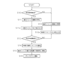
以下、通常運転モード時に冷媒の漏洩が生じた場合のコントローラ70によって実行される冷媒漏洩制御モードの処理の流れの一例を、図3のフローチャートを参照しながら説明する。
以下、通常運転モード時に冷媒の漏洩が生じた場合のコントローラ70によって実行される冷媒漏洩制御モードの処理の流れの一例を、図3のフローチャートを参照しながら説明する。
ステップS10では、冷房運転モードまたは暖房運転モードの通常運転モードが実行されている際に、コントローラ70は、冷房または暖房の運転開始または最新の漏洩冷媒ガス濃度の検出から所定期間が経過したか否かを判断する。ここで、所定期間経過していると判断した場合にはステップS11に移行する。所定期間経過していないと判断した場合にはステップS10を繰り返す。
ステップS11では、コントローラ70は、室内ファン53の駆動を一時的に停止させ、室内Rにおける空気流れを低減させる。
ステップS12では、コントローラ70は、冷媒ガスセンサ81における冷媒の検出濃度が所定冷媒濃度以上になっているか否かを判断する。当該所定冷媒濃度は、冷媒回路10に封入されている冷媒の種類(本実施形態ではR32)に応じて予め定められており、記憶部71に格納されている。コントローラ70が、冷媒ガスセンサ81において検出された冷媒濃度が所定冷媒濃度以上になっていると判断した場合には、ステップS14へ移行する。一方、冷媒ガスセンサ81において検出された冷媒濃度が所定冷媒濃度に満たない場合には、ステップS13に移行する。
ステップS13では、コントローラ70は、停止していた室内ファン53の駆動を再開させ、通常運転モードを継続させつつステップS10に戻る。
ステップS14では、コントローラ70は、冷媒漏洩制御モードを開始し、出力制御部75によって、冷媒が漏洩したことを表す情報をリモコン50aが有するディスプレイに文字情報として表示させる。また、コントローラ70は、出力制御部75によって、冷媒が漏洩したことを音声情報としてリモコン50aが有するスピーカから報知させる。
ステップS15では、コントローラ70は、室内ファン53の回転数が最大となるように強制的な運転状態に制御する。これにより、漏れだした冷媒媒を攪拌させ、局所的に濃度が高くなることを抑制させることが可能になる。
ステップS16では、ポンプダウン運転を行う。ポンプダウン運転では、四路切換弁22の接続状態を冷房運転モードの接続状態としつつ、室外膨張弁24を閉じて、圧縮機21を駆動させ、室外ファン25を駆動させて、室外熱交換器23を冷媒の凝縮器として機能させる。これにより、冷媒回路10のうち室内ユニット50側に存在している冷媒を室外ユニット2の圧縮機21の吐出側から室外熱交換器23を介して室外膨張弁24に至るまでの間に回収し、室内ユニット50における漏洩箇所からのさらなる冷媒の漏洩を抑制させる。なお、冷媒の漏洩時に冷房運転モードが実行される状態であれば、四路切換弁22の接続状態を維持したままで、ポンプダウン運転が行われることになる。他方、冷媒の漏洩時に暖房運転モードが実行される状態であれば、四路切換弁22を冷房運転モードでの接続状態に切り換えてポンプダウン運転が行われることになる。ポンプダウン運転は、吸入圧力センサ36の検出圧力が所定終了圧力以下になった場合に終了し、圧縮機21の駆動を停止させ、空気調和装置100の運転を停止させる。
(5)特徴
(5-1)
本実施形態に係る空気調和装置100の室内ユニット50では、冷媒ガスセンサ81が、調和空気Fが流れる領域からは外れる位置に設けられている。このため、冷媒ガスセンサ81が直接調和空気の流れに触れることを抑制することができるため、冷媒ガスセンサ81自体に結露が生じてしまうことを抑制することができる。これにより、冷媒ガスセンサ81における検知精度を高めることが可能になる。
(5-1)
本実施形態に係る空気調和装置100の室内ユニット50では、冷媒ガスセンサ81が、調和空気Fが流れる領域からは外れる位置に設けられている。このため、冷媒ガスセンサ81が直接調和空気の流れに触れることを抑制することができるため、冷媒ガスセンサ81自体に結露が生じてしまうことを抑制することができる。これにより、冷媒ガスセンサ81における検知精度を高めることが可能になる。
(5-2)
ここで、仮に、空気調和装置100が通常運転モードを実行中である場合に、室内ファン53を駆動させたままの状態で冷媒ガスセンサ81による検出を行おうとすると、漏洩した冷媒ガスは調和空気の流れFに沿うように室内ユニット50のケーシング60の前側下方の空間に導かれることになる。このため、室内ファン53を駆動させた状態で漏洩した冷媒を検出しようとすると、冷媒ガスセンサを調和空気の流れFが通過する領域に配置すべきことになる。しかし、調和空気の流れFが通過する領域に冷媒ガスセンサを配置してしまうと、上述したように冷媒ガスセンサに結露が生じ、正確な検出が困難になるおそれがある。
ここで、仮に、空気調和装置100が通常運転モードを実行中である場合に、室内ファン53を駆動させたままの状態で冷媒ガスセンサ81による検出を行おうとすると、漏洩した冷媒ガスは調和空気の流れFに沿うように室内ユニット50のケーシング60の前側下方の空間に導かれることになる。このため、室内ファン53を駆動させた状態で漏洩した冷媒を検出しようとすると、冷媒ガスセンサを調和空気の流れFが通過する領域に配置すべきことになる。しかし、調和空気の流れFが通過する領域に冷媒ガスセンサを配置してしまうと、上述したように冷媒ガスセンサに結露が生じ、正確な検出が困難になるおそれがある。
これに対して、本実施形態では、冷媒ガスセンサ81を室内ユニット50のケーシング60の底面63の下方の領域に配置しつつ、通常運転モードを実行中であっても、室内ファン53の駆動を停止させて室内Rにおける空気流れを小さく抑えた状態で、冷媒ガスセンサ81による検出を行っている。
このように、室内ファン53の駆動を停止させ、室内Rにおける空気流れが小さく抑えられているため、調和空気の流れFに導かれることなく、空気調和装置100の冷媒回路10に充填されている空気よりも比重の大きな冷媒であるR32は、漏洩時には自重によって、室内ユニット5のケーシング60の上方ではなく下方の領域に集まりがちになる。そして、冷媒ガスセンサ81が当該底面63の下方の領域に設けられているため、冷媒の漏洩をより確実に検出することが可能になっている。
(5-3)
本実施形態に係る空気調和装置100では、室内ユニット50において冷媒が漏洩し、燃焼可能性が生じた場合に、ポンプダウン運転を行って室外ユニット2に冷媒を回収させるため、室内ユニット50における漏洩箇所からのさらなる冷媒の漏洩を抑制することが可能になっている。
本実施形態に係る空気調和装置100では、室内ユニット50において冷媒が漏洩し、燃焼可能性が生じた場合に、ポンプダウン運転を行って室外ユニット2に冷媒を回収させるため、室内ユニット50における漏洩箇所からのさらなる冷媒の漏洩を抑制することが可能になっている。
(5-4)
本実施形態に係る空気調和装置100の室内ユニット50では、冷媒が漏洩したと判断された場合には、室内ファン53を強制的に最大回転数で駆動させるため、室内において局所的に冷媒濃度が高まっている箇所が生じることを抑制することが可能になっている。
本実施形態に係る空気調和装置100の室内ユニット50では、冷媒が漏洩したと判断された場合には、室内ファン53を強制的に最大回転数で駆動させるため、室内において局所的に冷媒濃度が高まっている箇所が生じることを抑制することが可能になっている。
(6)変形例
上記実施形態は、以下の変形例に示すように適宜変形が可能である。なお、各変形例は、矛盾が生じない範囲で他の変形例と組み合わせて適用されてもよい。
上記実施形態は、以下の変形例に示すように適宜変形が可能である。なお、各変形例は、矛盾が生じない範囲で他の変形例と組み合わせて適用されてもよい。
(6-1)変形例A
上記実施形態では、冷媒回路10に封入されている冷媒がR32である場合を例に挙げて説明した。
上記実施形態では、冷媒回路10に封入されている冷媒がR32である場合を例に挙げて説明した。
これに対して、冷媒回路10に封入される冷媒は、これに限定されるものではなく、例えば、R32以外の冷媒として、ASHRAE34の冷媒安全性分類規格がA3に分類される可燃性冷媒、ASHRAE34の冷媒安全性分類規格がA2に分類される弱燃性冷媒、ASHRAE34の冷媒安全性分類規格がA2Lに分類される微燃性冷媒、ASHRAE34の冷媒安全性分類規格のBに分類される強毒性冷媒を用いてもよい。
また、冷媒回路10に封入されるR32以外の冷媒としては、R32よりもGWPの低い冷媒(R717等の自然冷媒、R170、R1270、R290、R600、R600a、R152aまたはこれらの混合冷媒等)を用いてもよい。
(6-2)変形例B
変形例Aで説明したR32以外の冷媒のうち比重が空気よりも軽い冷媒(例えば、R717等の自然冷媒)を用いる場合には、例えば、図6に示す室内ユニット150のように、天面61に設けた開口61bに通信線81aを通過させて、天面61よりも上方の空間に冷媒ガスセンサ81を配置固定する。
変形例Aで説明したR32以外の冷媒のうち比重が空気よりも軽い冷媒(例えば、R717等の自然冷媒)を用いる場合には、例えば、図6に示す室内ユニット150のように、天面61に設けた開口61bに通信線81aを通過させて、天面61よりも上方の空間に冷媒ガスセンサ81を配置固定する。
これにより、漏洩した際に、空気よりも比重が軽いために上方に移動してくる冷媒をより正確に検出することができ、上記実施形態と同様の処理を行って同様の効果を得ることが可能になる。
(6-3)変形例C
上記実施形態では、通常運転モードが行われている際に、一時的に室内ファン53の駆動を停止させて、室内Rにおける空気流れを抑制して冷媒ガスセンサ81による検出を行う場合を例に挙げて説明した。
上記実施形態では、通常運転モードが行われている際に、一時的に室内ファン53の駆動を停止させて、室内Rにおける空気流れを抑制して冷媒ガスセンサ81による検出を行う場合を例に挙げて説明した。
これに対して、例えば、空気調和装置100の駆動が停止している状態においても、コントローラ70が冷媒ガスセンサ81からの検出信号を判断し、運転停止時においても冷媒の漏洩を検出できるようにしてもよい。空気調和装置100の停止時には、上記実施形態の通常運転モード実行時の一時的な室内ファン53の停止時と同様に、室内Rにおける空気流れが小さく抑えられるため、精度良く検出を行うことができる。
(6-4)変形例D
上記実施形態では、冷媒ガスセンサ81が室内ユニット50のケーシング60の下方の領域に常時固定されている場合を例に挙げて説明した。
上記実施形態では、冷媒ガスセンサ81が室内ユニット50のケーシング60の下方の領域に常時固定されている場合を例に挙げて説明した。
これに対して、例えば、図7に示す室内ユニット250のように、センサ昇降機構88を備え、冷媒ガスセンサ81を上下方向に移動させることが可能なようにしてもよい。
このセンサ昇降機構88は、室内ユニット制御部57と電気的に接続されており、図8に示す構成により、コントローラ70のアクチュエータ制御部74によって駆動制御される。具体的には、センサ昇降機構88は、降下している冷媒ガスセンサ81を上昇させる際には、通信線81aを巻き上げるように駆動され、冷媒ガスセンサ81を底面63に設けられた収納位置81bに収まるまで上昇させる。また、センサ昇降機構88は、収納位置81bに収まっている冷媒ガスセンサ81を下降させる際には、通信線81aを緩めるように駆動され、冷媒ガスセンサ81を底面63の下方の30mm以上300mm以下の所定の位置まで下降させる。
なお、冷媒ガスセンサ81を昇降させて用いる場合の処理についても、上記実施形態と同様であり、図9に示すように、上記実施形態のステップS11とS12との間に冷媒ガスセンサ81を下降させるステップS11xを実行し、さらにステップS12とステップS13との間に冷媒ガスセンサ81を上昇させるステップS12xを実行することで、上記実施形態と同様の効果を得ることができる。また、ここでは、冷媒ガスセンサ81を収容しておくことができるため、見た目をスッキリさせることができる。
(6-5)変形例E
上記実施形態では、冷媒が漏洩したことを示す報知において、リモコン50aのディスプレイによる文字情報の表示およびリモコン50aのスピーカを用いた音声情報による報知を行う場合を例に挙げて説明した。
上記実施形態では、冷媒が漏洩したことを示す報知において、リモコン50aのディスプレイによる文字情報の表示およびリモコン50aのスピーカを用いた音声情報による報知を行う場合を例に挙げて説明した。
これに対して、報知の態様としてはこれに限定されるものではなく、例えば、リモコン50aにランプが設けられている場合には、当該ランプを点灯、点滅等させるようにしてもよい。ここで、ランプによる報知を行う場合には、冷媒が漏洩していない正常状態であると判断された場合の発光状態と、冷媒が漏洩したと判断された場合の発光状態とを、発光の光量や点滅速度等を変える等して異なる態様で報知を行うようにしてもよい。
また、コントローラ70が、通信部72を介して、コンピュータによって構成される外部の遠隔監視装置等と通信ネットワークを通じて通信可能に接続されている場合には、当該外部の遠隔監視装置等に対して、冷媒が漏洩したことを示す情報を送信するようにしてもよい。この場合には、当該遠隔監視装置において監視を行っている冷媒漏洩の対処に詳しいサービスエンジニアに対しても状況を適切に把握させることが可能になる。
(6-6)変形例F
上記実施形態では、冷媒漏洩制御モードでは、最終的にポンプダウン運転を行って空気調和装置100を停止させる場合を例に挙げて説明した。
上記実施形態では、冷媒漏洩制御モードでは、最終的にポンプダウン運転を行って空気調和装置100を停止させる場合を例に挙げて説明した。
しかし、冷媒漏洩制御モードにおける空気調和装置100の制御としては、これに限定されるものではなく、例えば、漏洩後には圧縮機21の周波数を現状よりも低減させる制御を行うようにしてもよい。また、冷房運転モードの実行中に冷媒が漏洩した場合には、室内膨張弁54を閉じることにより、室内熱交換器52に対してさらなる冷媒が供給される状況を回避するようにしてもよい。
(6-7)変形例G
上記実施形態では、室内ユニット50と室外ユニット2とが互いに離れた場所に別々に配置されて構成される空気調和装置100を例に挙げて説明した。
上記実施形態では、室内ユニット50と室外ユニット2とが互いに離れた場所に別々に配置されて構成される空気調和装置100を例に挙げて説明した。
これに対して、上記実施形態における室内ユニット50の内部に収容されている構成要素と、室外ユニット2の内部に収容されている構成要素と、を1つの筐体内に収容しつつ、室内側と室外側とにまたがるように設置して用いられる空気調和装置としてもよい。
(6-8)変形例H
上記実施形態では、冷媒が漏洩した場合に、室内ファン53の回転数が最大となるように強制的な運転状態に制御する場合を例に挙げて説明した。
上記実施形態では、冷媒が漏洩した場合に、室内ファン53の回転数が最大となるように強制的な運転状態に制御する場合を例に挙げて説明した。
これに対して、例えば、空気調和装置100とは別に建物に備え付けられている換気設備のコントローラと空気調和装置100のコントローラ70とを通信可能に構成しつつ、冷媒が漏洩した場合において室内ファン53を強制的に運転させる際に、換気設備が備えるファンについても同時に強制運転させるようにしてもよい。
以上、本開示の実施形態を説明したが、特許請求の範囲に記載された本開示の趣旨及び範囲から逸脱することなく、形態や詳細の多様な変更が可能なことが理解されるであろう。
2 :室外ユニット
10 :冷媒回路
20 :室外ユニット制御部
21 :圧縮機
23 :室外熱交換器
24 :室外膨張弁
50 :室内ユニット
52 :室内熱交換器
53 :室内ファン(送風ファン)
54 :室内膨張弁
57 :室内ユニット制御部
60 :ケーシング
61 :天面(上面)
63 :底面(下面)
64 :吹出口
70 :コントローラ(制御部)
81 :冷媒ガスセンサ
81a :通信線
82 :空気温度センサ
83 :室内熱交温度センサ
88 :センサ昇降機構(昇降機構)
100 :空気調和装置(冷凍装置)
150 :室内ユニット
250 :室内ユニット
R :室内
10 :冷媒回路
20 :室外ユニット制御部
21 :圧縮機
23 :室外熱交換器
24 :室外膨張弁
50 :室内ユニット
52 :室内熱交換器
53 :室内ファン(送風ファン)
54 :室内膨張弁
57 :室内ユニット制御部
60 :ケーシング
61 :天面(上面)
63 :底面(下面)
64 :吹出口
70 :コントローラ(制御部)
81 :冷媒ガスセンサ
81a :通信線
82 :空気温度センサ
83 :室内熱交温度センサ
88 :センサ昇降機構(昇降機構)
100 :空気調和装置(冷凍装置)
150 :室内ユニット
250 :室内ユニット
R :室内
Claims (7)
- 冷媒が封入されており、冷凍サイクルを行う冷媒回路(10)を有する冷凍装置(100)の室内ユニット(50、150、250)であって、
前記冷媒回路の少なくとも一部を内部に収容しており、上下方向以外の方向に開口した吹出口(64)を有するケーシング(60)と、
前記ケーシングの内部に収容されており、前記吹出口から前記ケーシングの外部に向かう空気流れを生じさせる送風ファン(53)と、
前記ケーシングの下面(63)の下方、もしくは、前記ケーシングの上面(61)の上方において冷媒ガスを検出可能な冷媒ガスセンサ(81)と、
を備えた冷凍装置の室内ユニット。 - 前記冷媒回路に封入されている冷媒は、可燃性冷媒、弱燃性冷媒、微燃性冷媒、強毒性冷媒のいずれか1つの単体冷媒もしくは混合冷媒である、
請求項1に記載の冷凍装置の室内ユニット。 - 前記冷媒回路に封入されている冷媒は、R32、または、R32よりもGWPの低い冷媒である、
請求項1に記載の冷凍装置の室内ユニット。 - 前記冷媒ガスセンサは、前記ケーシングの下面から下方に30mm以上300mm以下の範囲で冷媒ガスの検出を行い、
前記ケーシングが室内(R)の壁面に固定された状態で用いられる、
請求項1から3のいずれか1項に記載の冷凍装置の室内ユニット。 - 前記冷媒ガスセンサは、前記ケーシングの下面から下方に30mm以上300mm以下の範囲に固定されている、
請求項4に記載の冷凍装置の室内ユニット(50)。 - 前記送風ファンの駆動を停止させた状態で、前記冷媒ガスセンサによる冷媒ガスの検出を行う制御部(70)をさらに備えた、
請求項4に記載の冷凍装置の室内ユニット。 - 前記冷媒ガスセンサを前記ケーシングの下面から下方に向けて出し入れするための昇降機構(88)をさらに備え、
前記制御部は、前記送風ファンの駆動を停止させた状態で前記昇降機構を用いて前記ケーシングの下面から下方に30mm以上300mm以下の位置まで前記冷媒ガスセンサを下降させて前記冷媒ガスセンサに冷媒ガスを検出させる、
請求項6に記載の冷凍装置の室内ユニット(250)。
Priority Applications (4)
| Application Number | Priority Date | Filing Date | Title |
|---|---|---|---|
| EP24188188.7A EP4421392A3 (en) | 2017-03-31 | 2018-03-28 | Indoor unit of refrigeration device |
| EP18777191.0A EP3604982B1 (en) | 2017-03-31 | 2018-03-28 | Indoor unit of refrigeration device |
| CN201880012641.5A CN110402360B (zh) | 2017-03-31 | 2018-03-28 | 冷冻装置的室内单元 |
| US16/492,982 US11131470B2 (en) | 2017-03-31 | 2018-03-28 | Indoor unit for refrigeration apparatus |
Applications Claiming Priority (2)
| Application Number | Priority Date | Filing Date | Title |
|---|---|---|---|
| JP2017072645A JP6555293B2 (ja) | 2017-03-31 | 2017-03-31 | 冷凍装置の室内ユニット |
| JP2017-072645 | 2017-03-31 |
Publications (1)
| Publication Number | Publication Date |
|---|---|
| WO2018181567A1 true WO2018181567A1 (ja) | 2018-10-04 |
Family
ID=63677892
Family Applications (1)
| Application Number | Title | Priority Date | Filing Date |
|---|---|---|---|
| PCT/JP2018/012959 Ceased WO2018181567A1 (ja) | 2017-03-31 | 2018-03-28 | 冷凍装置の室内ユニット |
Country Status (5)
| Country | Link |
|---|---|
| US (1) | US11131470B2 (ja) |
| EP (2) | EP3604982B1 (ja) |
| JP (1) | JP6555293B2 (ja) |
| CN (1) | CN110402360B (ja) |
| WO (1) | WO2018181567A1 (ja) |
Cited By (1)
| Publication number | Priority date | Publication date | Assignee | Title |
|---|---|---|---|---|
| US11260728B2 (en) | 2019-07-02 | 2022-03-01 | Carrier Corporation | Distributed hazard detection system for a transport refrigeration system |
Families Citing this family (17)
| Publication number | Priority date | Publication date | Assignee | Title |
|---|---|---|---|---|
| US10119738B2 (en) | 2014-09-26 | 2018-11-06 | Waterfurnace International Inc. | Air conditioning system with vapor injection compressor |
| US10871314B2 (en) | 2016-07-08 | 2020-12-22 | Climate Master, Inc. | Heat pump and water heater |
| US10866002B2 (en) | 2016-11-09 | 2020-12-15 | Climate Master, Inc. | Hybrid heat pump with improved dehumidification |
| US11592215B2 (en) | 2018-08-29 | 2023-02-28 | Waterfurnace International, Inc. | Integrated demand water heating using a capacity modulated heat pump with desuperheater |
| US11976829B2 (en) * | 2019-01-09 | 2024-05-07 | Mitsubishi Electric Corporation | Air-conditioning apparatus |
| CA3081986A1 (en) | 2019-07-15 | 2021-01-15 | Climate Master, Inc. | Air conditioning system with capacity control and controlled hot water generation |
| US11231198B2 (en) | 2019-09-05 | 2022-01-25 | Trane International Inc. | Systems and methods for refrigerant leak detection in a climate control system |
| US11326797B2 (en) * | 2020-04-14 | 2022-05-10 | Haier Us Appliance Solutions, Inc. | Gas sensing system for an air conditioner unit |
| JP2021173435A (ja) * | 2020-04-21 | 2021-11-01 | 三菱電機株式会社 | 冷凍サイクル装置 |
| US20230131781A1 (en) * | 2020-05-11 | 2023-04-27 | Mitsubishi Electric Corporation | Refrigeration cycle apparatus |
| EP3974735B1 (en) * | 2020-09-25 | 2026-04-29 | Daikin Industries, Ltd. | Indoor unit of a heat pump |
| CN114623588A (zh) * | 2020-12-09 | 2022-06-14 | 广东美的制冷设备有限公司 | 空调室内机和空调器 |
| US12181189B2 (en) | 2021-11-10 | 2024-12-31 | Climate Master, Inc. | Ceiling-mountable heat pump system |
| US12487008B2 (en) | 2022-01-14 | 2025-12-02 | Trane International Inc. | Method of commissioning an HVAC system |
| US12117191B2 (en) | 2022-06-24 | 2024-10-15 | Trane International Inc. | Climate control system with improved leak detector |
| JP2024164488A (ja) * | 2023-05-15 | 2024-11-27 | パナソニックIpマネジメント株式会社 | 空気調和機 |
| JP7674419B2 (ja) * | 2023-06-23 | 2025-05-09 | 日立ジョンソンコントロールズ空調株式会社 | 空気調和機及び空気調和システム |
Citations (6)
| Publication number | Priority date | Publication date | Assignee | Title |
|---|---|---|---|---|
| JPH06180166A (ja) * | 1992-12-09 | 1994-06-28 | Toshiba Corp | 空気調和機 |
| JPH09318208A (ja) * | 1996-06-03 | 1997-12-12 | Daikin Ind Ltd | 可燃性冷媒を用いた冷凍装置 |
| JP2005016822A (ja) * | 2003-06-25 | 2005-01-20 | Toshiba Kyaria Kk | 可燃性冷媒空気調和機の冷媒漏洩検知装置 |
| JP2016090109A (ja) | 2014-10-31 | 2016-05-23 | ダイキン工業株式会社 | 空気調和機の室内機 |
| JP2016196996A (ja) * | 2015-04-06 | 2016-11-24 | ダイキン工業株式会社 | 利用側空調装置及びそれを備えた空調装置 |
| JP2017084656A (ja) * | 2015-10-29 | 2017-05-18 | 三菱電機株式会社 | コンセント、そのカバープレート及び冷媒検知装置、並びに、コンセント又は冷媒検知装置を備えた環境監視システム |
Family Cites Families (12)
| Publication number | Priority date | Publication date | Assignee | Title |
|---|---|---|---|---|
| JP4386544B2 (ja) * | 2000-05-26 | 2009-12-16 | 三洋電機株式会社 | 空気調和機 |
| WO2002027245A1 (fr) * | 2000-09-26 | 2002-04-04 | Daikin Industries, Ltd. | Climatiseur |
| JP2002195718A (ja) * | 2000-12-28 | 2002-07-10 | Nakano Refrigerators Co Ltd | ショーケース等の集中管理装置 |
| CN202133061U (zh) * | 2008-11-26 | 2012-02-01 | 德尔福技术有限公司 | 制冷剂泄漏探测系统及其制冷剂传感器组件 |
| JP2011202831A (ja) * | 2010-03-25 | 2011-10-13 | Hitachi Appliances Inc | リモートコントローラ及び室内ユニット並びに空気調和機 |
| JP5818849B2 (ja) * | 2013-08-26 | 2015-11-18 | 三菱電機株式会社 | 空気調和装置および冷媒漏洩検知方法 |
| JP5812081B2 (ja) * | 2013-11-12 | 2015-11-11 | ダイキン工業株式会社 | 室内機 |
| JP6431339B2 (ja) * | 2014-11-07 | 2018-11-28 | 日立ジョンソンコントロールズ空調株式会社 | 室内機、および、それを備える空気調和機 |
| JP6466219B2 (ja) * | 2015-03-20 | 2019-02-06 | 日立ジョンソンコントロールズ空調株式会社 | 空気調和機の室内機 |
| JP6572628B2 (ja) * | 2015-05-27 | 2019-09-11 | ダイキン工業株式会社 | 空調換気システム |
| GB2554267B (en) | 2015-06-30 | 2020-12-16 | Mitsubishi Electric Corp | Refrigerant leakage detection system |
| CN205664530U (zh) * | 2016-05-26 | 2016-10-26 | 福建龙峰纺织科技实业有限公司 | 一种纺织车间的空调传感器支架 |
-
2017
- 2017-03-31 JP JP2017072645A patent/JP6555293B2/ja active Active
-
2018
- 2018-03-28 US US16/492,982 patent/US11131470B2/en active Active
- 2018-03-28 EP EP18777191.0A patent/EP3604982B1/en active Active
- 2018-03-28 WO PCT/JP2018/012959 patent/WO2018181567A1/ja not_active Ceased
- 2018-03-28 CN CN201880012641.5A patent/CN110402360B/zh active Active
- 2018-03-28 EP EP24188188.7A patent/EP4421392A3/en active Pending
Patent Citations (6)
| Publication number | Priority date | Publication date | Assignee | Title |
|---|---|---|---|---|
| JPH06180166A (ja) * | 1992-12-09 | 1994-06-28 | Toshiba Corp | 空気調和機 |
| JPH09318208A (ja) * | 1996-06-03 | 1997-12-12 | Daikin Ind Ltd | 可燃性冷媒を用いた冷凍装置 |
| JP2005016822A (ja) * | 2003-06-25 | 2005-01-20 | Toshiba Kyaria Kk | 可燃性冷媒空気調和機の冷媒漏洩検知装置 |
| JP2016090109A (ja) | 2014-10-31 | 2016-05-23 | ダイキン工業株式会社 | 空気調和機の室内機 |
| JP2016196996A (ja) * | 2015-04-06 | 2016-11-24 | ダイキン工業株式会社 | 利用側空調装置及びそれを備えた空調装置 |
| JP2017084656A (ja) * | 2015-10-29 | 2017-05-18 | 三菱電機株式会社 | コンセント、そのカバープレート及び冷媒検知装置、並びに、コンセント又は冷媒検知装置を備えた環境監視システム |
Non-Patent Citations (1)
| Title |
|---|
| See also references of EP3604982A4 |
Cited By (1)
| Publication number | Priority date | Publication date | Assignee | Title |
|---|---|---|---|---|
| US11260728B2 (en) | 2019-07-02 | 2022-03-01 | Carrier Corporation | Distributed hazard detection system for a transport refrigeration system |
Also Published As
| Publication number | Publication date |
|---|---|
| CN110402360B (zh) | 2021-04-30 |
| EP3604982A4 (en) | 2020-11-25 |
| JP2018173249A (ja) | 2018-11-08 |
| US20200018504A1 (en) | 2020-01-16 |
| EP3604982B1 (en) | 2024-08-21 |
| JP6555293B2 (ja) | 2019-08-07 |
| EP3604982A1 (en) | 2020-02-05 |
| CN110402360A (zh) | 2019-11-01 |
| US11131470B2 (en) | 2021-09-28 |
| EP4421392A2 (en) | 2024-08-28 |
| EP4421392A3 (en) | 2024-10-30 |
Similar Documents
| Publication | Publication Date | Title |
|---|---|---|
| JP6555293B2 (ja) | 冷凍装置の室内ユニット | |
| JP6477767B2 (ja) | 冷凍装置 | |
| JP6935720B2 (ja) | 冷凍装置 | |
| JP6375639B2 (ja) | 空気調和装置 | |
| CN207395264U (zh) | 制冷循环装置以及制冷循环系统 | |
| US10724766B2 (en) | Refrigeration cycle apparatus | |
| JP2013036716A (ja) | 室外機及びその室外機を備えた冷凍サイクル装置 | |
| KR20100059522A (ko) | 공기조화기의 제어방법 | |
| WO2019163346A1 (ja) | 空気調和機 | |
| WO2015199190A1 (ja) | 空調室内機 | |
| JP2019039599A (ja) | 空気調和装置 | |
| JP7187898B2 (ja) | 冷凍サイクル装置 | |
| JP2011137597A (ja) | 空気調和装置 | |
| JP2002147905A (ja) | 冷凍装置 | |
| JP2022024290A (ja) | 空気調和機 | |
| JP7048880B2 (ja) | 冷凍空調装置 | |
| CN116981893A (zh) | 空调机 | |
| JP6853205B2 (ja) | 低能力室内機 | |
| KR101186326B1 (ko) | 공기조화기 및 그 제어방법 | |
| JP2016156569A (ja) | 冷凍装置 | |
| CN117396705B (zh) | 空调机 | |
| KR20100048548A (ko) | 공기조화기 및 그 제어방법 | |
| US20240085042A1 (en) | Refrigeration cycle device and refrigerant leakage determination system | |
| KR20190000584A (ko) | 공기 조화기 | |
| KR20070079380A (ko) | 공기조화기 및 그 제어방법 |
Legal Events
| Date | Code | Title | Description |
|---|---|---|---|
| 121 | Ep: the epo has been informed by wipo that ep was designated in this application |
Ref document number: 18777191 Country of ref document: EP Kind code of ref document: A1 |
|
| NENP | Non-entry into the national phase |
Ref country code: DE |
|
| WWE | Wipo information: entry into national phase |
Ref document number: 2018777191 Country of ref document: EP |
|
| ENP | Entry into the national phase |
Ref document number: 2018777191 Country of ref document: EP Effective date: 20191031 |