WO2018181779A1 - 水硬性石灰を用いた成形体およびその製造方法 - Google Patents
水硬性石灰を用いた成形体およびその製造方法 Download PDFInfo
- Publication number
- WO2018181779A1 WO2018181779A1 PCT/JP2018/013373 JP2018013373W WO2018181779A1 WO 2018181779 A1 WO2018181779 A1 WO 2018181779A1 JP 2018013373 W JP2018013373 W JP 2018013373W WO 2018181779 A1 WO2018181779 A1 WO 2018181779A1
- Authority
- WO
- WIPO (PCT)
- Prior art keywords
- hydraulic lime
- carbon dioxide
- curing
- aggregate
- lime
- Prior art date
- Legal status (The legal status is an assumption and is not a legal conclusion. Google has not performed a legal analysis and makes no representation as to the accuracy of the status listed.)
- Ceased
Links
Images





Classifications
-
- B—PERFORMING OPERATIONS; TRANSPORTING
- B28—WORKING CEMENT, CLAY, OR STONE
- B28B—SHAPING CLAY OR OTHER CERAMIC COMPOSITIONS; SHAPING SLAG; SHAPING MIXTURES CONTAINING CEMENTITIOUS MATERIAL, e.g. PLASTER
- B28B3/00—Producing shaped articles from the material by using presses; Presses specially adapted therefor
-
- C—CHEMISTRY; METALLURGY
- C04—CEMENTS; CONCRETE; ARTIFICIAL STONE; CERAMICS; REFRACTORIES
- C04B—LIME, MAGNESIA; SLAG; CEMENTS; COMPOSITIONS THEREOF, e.g. MORTARS, CONCRETE OR LIKE BUILDING MATERIALS; ARTIFICIAL STONE; CERAMICS; REFRACTORIES; TREATMENT OF NATURAL STONE
- C04B28/00—Compositions of mortars, concrete or artificial stone, containing inorganic binders or the reaction product of an inorganic and an organic binder, e.g. polycarboxylate cements
- C04B28/02—Compositions of mortars, concrete or artificial stone, containing inorganic binders or the reaction product of an inorganic and an organic binder, e.g. polycarboxylate cements containing hydraulic cements other than calcium sulfates
- C04B28/10—Lime cements or magnesium oxide cements
- C04B28/12—Hydraulic lime
-
- B—PERFORMING OPERATIONS; TRANSPORTING
- B28—WORKING CEMENT, CLAY, OR STONE
- B28B—SHAPING CLAY OR OTHER CERAMIC COMPOSITIONS; SHAPING SLAG; SHAPING MIXTURES CONTAINING CEMENTITIOUS MATERIAL, e.g. PLASTER
- B28B11/00—Apparatus or processes for treating or working the shaped or preshaped articles
- B28B11/24—Apparatus or processes for treating or working the shaped or preshaped articles for curing, setting or hardening
-
- B—PERFORMING OPERATIONS; TRANSPORTING
- B28—WORKING CEMENT, CLAY, OR STONE
- B28B—SHAPING CLAY OR OTHER CERAMIC COMPOSITIONS; SHAPING SLAG; SHAPING MIXTURES CONTAINING CEMENTITIOUS MATERIAL, e.g. PLASTER
- B28B3/00—Producing shaped articles from the material by using presses; Presses specially adapted therefor
- B28B3/02—Producing shaped articles from the material by using presses; Presses specially adapted therefor wherein a ram exerts pressure on the material in a moulding space; Ram heads of special form
-
- C—CHEMISTRY; METALLURGY
- C04—CEMENTS; CONCRETE; ARTIFICIAL STONE; CERAMICS; REFRACTORIES
- C04B—LIME, MAGNESIA; SLAG; CEMENTS; COMPOSITIONS THEREOF, e.g. MORTARS, CONCRETE OR LIKE BUILDING MATERIALS; ARTIFICIAL STONE; CERAMICS; REFRACTORIES; TREATMENT OF NATURAL STONE
- C04B28/00—Compositions of mortars, concrete or artificial stone, containing inorganic binders or the reaction product of an inorganic and an organic binder, e.g. polycarboxylate cements
- C04B28/02—Compositions of mortars, concrete or artificial stone, containing inorganic binders or the reaction product of an inorganic and an organic binder, e.g. polycarboxylate cements containing hydraulic cements other than calcium sulfates
- C04B28/10—Lime cements or magnesium oxide cements
-
- C—CHEMISTRY; METALLURGY
- C04—CEMENTS; CONCRETE; ARTIFICIAL STONE; CERAMICS; REFRACTORIES
- C04B—LIME, MAGNESIA; SLAG; CEMENTS; COMPOSITIONS THEREOF, e.g. MORTARS, CONCRETE OR LIKE BUILDING MATERIALS; ARTIFICIAL STONE; CERAMICS; REFRACTORIES; TREATMENT OF NATURAL STONE
- C04B40/00—Processes, in general, for influencing or modifying the properties of mortars, concrete or artificial stone compositions, e.g. their setting or hardening ability
- C04B40/02—Selection of the hardening environment
- C04B40/0231—Carbon dioxide hardening
-
- C—CHEMISTRY; METALLURGY
- C04—CEMENTS; CONCRETE; ARTIFICIAL STONE; CERAMICS; REFRACTORIES
- C04B—LIME, MAGNESIA; SLAG; CEMENTS; COMPOSITIONS THEREOF, e.g. MORTARS, CONCRETE OR LIKE BUILDING MATERIALS; ARTIFICIAL STONE; CERAMICS; REFRACTORIES; TREATMENT OF NATURAL STONE
- C04B7/00—Hydraulic cements
- C04B7/34—Hydraulic lime cements; Roman cements ; natural cements
-
- C—CHEMISTRY; METALLURGY
- C04—CEMENTS; CONCRETE; ARTIFICIAL STONE; CERAMICS; REFRACTORIES
- C04B—LIME, MAGNESIA; SLAG; CEMENTS; COMPOSITIONS THEREOF, e.g. MORTARS, CONCRETE OR LIKE BUILDING MATERIALS; ARTIFICIAL STONE; CERAMICS; REFRACTORIES; TREATMENT OF NATURAL STONE
- C04B2201/00—Mortars, concrete or artificial stone characterised by specific physical values
- C04B2201/50—Mortars, concrete or artificial stone characterised by specific physical values for the mechanical strength
-
- Y—GENERAL TAGGING OF NEW TECHNOLOGICAL DEVELOPMENTS; GENERAL TAGGING OF CROSS-SECTIONAL TECHNOLOGIES SPANNING OVER SEVERAL SECTIONS OF THE IPC; TECHNICAL SUBJECTS COVERED BY FORMER USPC CROSS-REFERENCE ART COLLECTIONS [XRACs] AND DIGESTS
- Y02—TECHNOLOGIES OR APPLICATIONS FOR MITIGATION OR ADAPTATION AGAINST CLIMATE CHANGE
- Y02P—CLIMATE CHANGE MITIGATION TECHNOLOGIES IN THE PRODUCTION OR PROCESSING OF GOODS
- Y02P40/00—Technologies relating to the processing of minerals
- Y02P40/10—Production of cement, e.g. improving or optimising the production methods; Cement grinding
- Y02P40/18—Carbon capture and storage [CCS]
Definitions
- the present invention relates to a molded body using hydraulic lime and a method for producing the same.
- hydraulic lime As a building material, and it has been known from the ancient Roman period (BC 2nd century) that it solidifies when dissolved in water and left to dry.
- natural hydraulic lime obtained by burning siliceous natural limestone, adding water and digesting, and artificial hydraulic lime in which slaked lime is mixed with a material that expresses a porazone substance or hydraulic property.
- hydraulic lime does not dissolve in water after curing, it has an excellent feature that the reinforcing bars are not easily rusted when used in composite building materials containing reinforcing bars. Currently, it is not used as a building structural member.
- An object of the present invention is to provide a method for producing a molded body containing hydraulic lime, a molded body, and a member.
- the present invention for solving the above-described problems is composed of the following.
- (2) (a) a step of press-molding a mixture containing hydraulic lime and water at a pressure of 5 N / mm 2 or more, and (b) a step of subjecting the press-formed body obtained in (a) to carbon dioxide curing.
- the manufacturing method of the molded object containing the hydraulic lime of 1st embodiment which concerns on this invention is a process which press-molds the mixture containing hydraulic lime and water at a pressure of 5 N / mm ⁇ 2 > or more, and (b). It is a manufacturing method including the process of using the press-molded body obtained in (a) for carbon dioxide curing.
- the manufacturing method in this embodiment is a manufacturing method including the step of press-molding a mixture containing hydraulic lime and water at a pressure of 5 N / mm 2 or more.
- the mixture of this embodiment comprises hydraulic lime and water.
- the hydraulic lime in the present embodiment includes natural hydraulic lime (NHL, Natural Hydraulic Lime) and artificial hydraulic lime (HL, Hydraulic Lime) in which slaked lime is mixed with a material that expresses a polazone substance or hydraulic property. .
- Natural hydraulic lime means lime obtained by baking clayey or siliceous limestone (also called marlstone, marl). It means lime made by baking some powdered, clayey or siliceous limestone. All NHLs are hydraulic. Carbon dioxide in the atmosphere contributes to hardening.
- the main components of natural hydraulic lime are calcium hydroxide (Ca (OH) 2 ), calcium carbonate (CaCO 3 ), dicalcium silicate (2CaO ⁇ SiO 2 , belite, hereinafter C 2 S), silicon dioxide (SiO 2 ) 2 ).
- Ca (OH) 2 ) 2 calcium carbonate
- C 2 S dicalcium silicate
- SiO 2 silicon dioxide
- Table 1 the chemical analysis results are about 60% CaO and 10 to 20% SiO 2 due to hydraulic properties. Cement coefficient in Table 1 I.
- Cementation Index is one of the indexes indicating the degree of hydraulic property, and is calculated by the following formula.
- Natural hydraulic lime has historically been the basis of the invention of cement and is a material with an increased hydration component.
- the chemical composition of cement is almost the same as that of natural hydraulic lime, but in addition to C 2 S, tricalcium silicate (3CaO ⁇ SiO 2 , alite, hereinafter C 3 S), calcium aluminate (3CaO ⁇ Al 2 O 3 , aluminate, C 3 A), calcium aluminoferrite (4CaO ⁇ Al 2 O 3 ⁇ Fe 2 O 3 , ferrite, C 4 AF) and other clinker and calcium sulfate (CaSO 4 ⁇ 2H 2 O, gypsum) Is included.
- C 3 S and C 2 S are both silicates, and both are collectively referred to as “silicate phase”.
- C 3 A and C 4 AF are present in the gap portion of the silicate phase in the clinker, and are collectively referred to as “gap phase”.
- Each clinker mineral has different properties such as hydration reaction rate, strength development, and heat of hydration.
- Various cements having different physical properties can be produced by changing the composition of such clinker minerals having different properties and further changing the amount of gypsum added, the fineness of the cement (specific surface area value), and the like.
- the clinker percentage is about 10-25% for NHL2, about 25-40% for NHL3.5, and about 40-50% for NHL5.
- Slaked lime is mainly composed of calcium hydroxide, and so-called impurities such as SiO 2 , Al 2 O 3 , Fe 2 O 3 , and MgO are extremely small compared to natural hydraulic lime, and no hydration reaction occurs.
- artificial hydraulic lime Compared to natural hydraulic lime, artificial hydraulic lime is called so-called Roman cement or ancient cement, and in European standard EN4599-1, it is mainly composed of calcium hydroxide, calcium silicate and calcium aluminate. Lime made by mixing these materials with hydraulic properties. Carbon dioxide in the atmosphere contributes to curing. ”
- the artificial hydraulic lime means that slaked lime added with pozzolanic material (a mineral such as silicic acid (SiO 2 ), alumina (Al 2 O 3 ), iron oxide (Fe 2 O 3 )) later. However, it is distinguished from natural hydraulic lime.
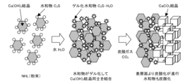
- Hardening mechanism of hydraulic lime Slaked lime obtained by calcination and digestion of limestone (CaCO 3 , calcium carbonate) is reduced to the original limestone by combining with carbon dioxide (CO 2 ) in the air (hereinafter referred to as carbonation). It has the nature to be. Slaked lime is an air-hard material, and after hardening by mixing with water, the CaCO 3 crystals that are produced do not bond and do not develop strength. Natural hydraulic lime is obtained by baking and digesting siliceous limestone containing SiO 2 and the like, and is lime containing Ca (OH) 2 as a main component and hydrates such as C 2 S.
- the hydrate In contact with water, the hydrate binds Ca (OH) 2 crystals, and further, due to carbonation, Ca (OH) 2 gradually changes from the surface layer to CaCO 3 crystals.
- CaCO 3 crystals are kept in a bound state by hydrates, and the hydrates are converted to CaCO 3 crystals by the same carbonation action (calcium carbonate crystallization).
- the CaCO 3 crystals form a granular structure including voids, and carbon dioxide in the air is supplied to the inner Ca (OH) 2 , and the carbonation proceeds slowly.
- natural hydraulic lime is a material having both hydraulic properties and air hardness, and develops strength after being cured by mixing with water. Its strength is as specified in the European standard EN459-1.
- FIG. 1 the conceptual diagram of the hardening mechanism of hydraulic lime is shown.
- Hydraulic lime can be classified according to compressive strength into the following three types defined in European standard EN459-1 (28-day strength by underwater curing). HL2, NHL2 2-7 N / mm 2 HL3.5, NHL3.5 3.5-10 N / mm 2 HL5, NHL5 5-15 N / mm 2
- hydraulic lime such as NHL2, NHL3.5, NHL5, HL2, HL3.5, HL5 can be used, but is not limited thereto.
- Natural hydraulic lime has some variation depending on the place of production, but it may be any material that contains Ca (OH) 2 , CaCO 3 , C 2 S, and SiO 2 as main components. Natural hydraulic lime is famous from France, but may be from other origins such as Tunisia and Italy.
- the hydraulic lime preferably has a cement coefficient of 0.45 to 0.96, more preferably 0.5 to 0.88, and still more preferably 0.5 to 0.75. When the cement coefficient is less than 0.45 or more than 0.96, the effect of strength development by carbon dioxide curing is not so high.
- the mixture containing hydraulic lime and water preferably contains 5 to 15% by mass of water based on hydraulic lime.
- the water mixed with the hydraulic lime may be water in which carbon dioxide gas is dissolved.
- Press molding is a method of obtaining a molded body by applying deformation such as compression to a material using a processing machine, a die, a tool, etc., and as a molding form, drawing, deep drawing, flange, call Examples include gates, edge curling, stamping and the like.
- a press molding method in which molding is performed using a mold, a rubber press method (hydrostatic pressure molding method), a roller molding method, an extrusion molding method, a casting molding method, and the like.
- molding may be performed using a metal mold from the viewpoint of molding pressure.
- the bending strength is improved if the pressure of press molding is 5 N / mm 2 or more, preferably 10 N / mm 2 or more, more preferably 15 N / mm 2 or more, and 30 N / mm 2 or more. Is more preferable.
- a press-molded body means a molded body obtained by press-molding a mixture containing hydraulic lime and water.
- the mixture may further include aggregate.
- Natural aggregates, artificial aggregates, and recycled aggregates can be used as the aggregates used in the present embodiment, but are not limited to these.
- natural aggregates include river sand, river gravel, mountain sand, mountain gravel, calcium carbonate, zeolite, vermiculite, diatomaceous earth and the like.
- the artificial aggregate include an artificial lightweight aggregate obtained by firing blast furnace slag aggregate, fly ash and the like at a high temperature.
- recycled aggregates include aggregates and waste glass taken from concrete waste. Standard sand for cement strength test (JIS R 5201) used as an aggregate of cement, No. 5, silica sand, No. 6 silica sand and No.
- silica sand may be used as aggregates, or slaked lime may be used. it can.
- the strength expression can be improved by adjusting the blending ratio of the aggregate and hydraulic lime.
- the aggregate has a maximum particle size of preferably 5 mm or less, more preferably 1 mm or less, and even more preferably 150 ⁇ m or less.
- the peak value of the particle size distribution of the aggregate is preferably 30 to 1000 ⁇ m, more preferably 30 to 500 ⁇ m, and further preferably 30 to 150 ⁇ m.
- the mixture can include lattice-like, mesh-like or shaft-like reinforcements therein.
- the lattice-like, mesh-like or shaft-like reinforcing material may be made of metal such as iron, resin, glass fiber, carbon fiber, or vegetable fiber, but is not limited thereto.
- the manufacturing method of the molded object of this embodiment does not require a heating process, it can also contain various components in a mixture.
- Ingredients include: pulp, bamboo and other plant fibers, gum arabic, natural rubber, casein, cellulose and other natural resins, acrylic and vinyl acetate synthetic resins, carbon fibers and charcoal carbon materials, zinc and indium , Gallium, tin, bismuth, lead, gold, silver, platinum and other low melting point metals or alloys or compounds thereof.
- an adsorbent such as a carbon-based material, a molded body having a deodorizing action can be obtained.
- it can color by adding a pigment, dye, etc.
- the manufacturing method in the present embodiment is a manufacturing method including a step of subjecting the press-formed body to carbon dioxide curing.
- the period of carbon dioxide curing is a necessary and sufficient period for the press-formed body of the mixture containing hydraulic lime and water to be cured.
- the period varies depending on the size of the molded body, the ambient environment temperature, the humidity, and the like, but is generally preferably 2 days or more and more preferably 3 days or more. Desirably, 7 days or more is more desirable.
- the press-molded body is not constrained by the mold and has many release surfaces, the time required for curing is shortened compared to the carbon dioxide curing in a state constrained by the mold.
- the carbon dioxide gas concentration in the carbon dioxide curing is higher than the atmospheric concentration (approximately 0.03%), the effect of strength development can be expected.
- the carbon dioxide gas concentration is 1% by volume or more.
- High strength can be expressed at an early stage with carbon dioxide curing of 5% by volume or more, and high strength can be expressed at an earlier stage by using carbon dioxide curing at a higher concentration such as 10% or 20% by volume. be able to.
- Carbon dioxide curing can be adjusted according to the size of building materials to be manufactured and the surrounding environment. For example, when using a 100 ⁇ 100 ⁇ 10 mm press-molded body, the press-molded body is placed on the shelf of the carbon dioxide gas curing chamber, and then the door is closed to make the inside hermetically sealed. Thereafter, the air in the curing room is once degassed, and then carbon dioxide is injected to a desired concentration. In order to maintain a desired carbon dioxide concentration, carbon dioxide is appropriately injected automatically or manually. When using a carbon dioxide gas curing pot, it can also be performed in a pressurized environment. When placing at a construction site, a temporary carbon dioxide curing room can be installed around the press molded body to inject carbon dioxide.
- the bending strength of the molded body containing hydraulic lime produced by the production method of the present embodiment is the maximum moment until the specimen breaks in the bending test with both ends supported and loaded in the center. Bending stress value calculated by dividing by a coefficient.
- the molded body manufactured by the manufacturing method of the present embodiment is characterized by having a bending strength of 7.5 N / mm 2 or more, more preferably a bending strength of 8 N / mm 2 or more.
- the pressing pressure, the particle size and blending ratio of the aggregate by adjusting the carbon dioxide curing conditions, 10 N / mm 2 or more, and 19N / mm 2 or more, further 23N / mm 2 or more It is possible to produce a molded body containing hydraulic lime having a bending strength of.
- the molded body comprising calcium carbonate crystallized hydraulic lime according to the present embodiment is preferably 1.5 g / cm 3 or more, more preferably 1.65 g / cm 3 or more, more preferably 1.7 g / cm It has a density of 3 or more, particularly preferably 1.9 g / cm 3 or more.
- the molded object containing hydraulic lime in one embodiment of the present invention can be used as a member by processing.
- the member include building members such as tiles, panels and boards, tableware, daily necessities, machine parts, electric appliances and the like.
- Example 1 Preparation of test specimen 1.1.
- Material naturally hydraulic lime
- the hydraulic lime used for the preparation of the test specimen is NHL2 from A production area (eastern France), and these chemical components are as shown in Table 1.
- Table 1 (aggregate) No. 5 silica sand (Mikawa silica sand), No. 6 silica sand (Mikawa silica sand), No. 8 silica sand (Mikawa silica sand) with different particle size distribution as aggregates, and peak particle size distribution with a maximum diameter of 250 ⁇ m or less.
- Calcium carbonate (Hitachi crushed stone) having a value of 40 to 100 ⁇ m was used.
- Table 2 shows the parameters of the manufactured test specimens.
- amount of water According to the provisions of European standard EN459-2, 55% by weight of water was added to hydraulic lime and press-molded. As a result, no press-molded body was obtained. It was 10 mass% with respect to hard lime.
- a moisture amount of 55% by mass was added to hydraulic lime as defined in European standard EN459-2.
- aggregate The blending amount of the aggregate at the time of preparing the test body was 1: 1, 1: 2, and 1: 4 with respect to hydraulic lime.
- Curing conditions are: air curing (during implementation) (temperature 20 ⁇ 1 ° C, relative humidity 60 ⁇ 5%), carbon dioxide curing (temperature 20 ⁇ 1 ° C, relative humidity 60 ⁇ 5%, carbon dioxide concentration 5%) Two types of tests were conducted.
- the curing conditions for the non-compression molded specimens are as follows.
- Patent Document 1 refers to a two-day underwater curing (mold frame sealed with a plastic plate for two days), a carbon dioxide gas curing after demolding, and an open mold. The carbon dioxide gas was cured while being installed, and after 7 days, the mold was removed and the carbon dioxide gas was cured again.
- Measurement of bending strength of test specimen The test for measuring the bending strength was performed by preparing a 100 ⁇ 100 ⁇ 10 mm specimen. Two specimens were taken as one set, the bending strength was measured, and the average value of the two specimens was taken. The measurement was performed using a 20 kN universal testing machine (manufactured by Shimadzu Corporation). The test body was applied by a one-way monotonic force with a three-point support by a universal testing machine, and the loading speed was controlled from 1 to 10 N / sec while taking into account the maximum strength. The bending strength by three-point bending is calculated by the following formula.
- ⁇ 3PD / 2bh 2
- ⁇ the bending strength (N / mm 2 )
- P the breaking load (N)
- D the supporting fulcrum distance (mm)
- bh 2 the dimension of the molded body (width b (mm), h (mm ))
- D 90 mm.
- the maximum strength is expressed in the curing period of 3 days, except when the molding pressure is 40 N / mm 2 .
- the molding pressure is the case of 40N / mm 2, expressed maximum intensity in 7 days. From this, it can be considered that when the compressive force at the time of molding is increased, the distance between crystals is shortened, and it becomes difficult for carbon dioxide gas to pass, so that it takes time to develop strength.
- the bending strength is 2 N / mm 2 or less, so that it can be confirmed that the carbon dioxide gas curing affects the strength increase.
- Example 2 Preparation of Specimen Using the material used in Example 1, the amount of water is adjusted as appropriate to produce a specimen having the same dimensions as in Example 1, and mixed with molding pressure, carbon dioxide curing concentration, and hydraulic lime. A bending test was performed again to supplement the effect of the presence or absence of aggregates. Table 3 shows the parameters of the manufactured specimens. On the molding pressure of 10 ⁇ 40N / mm 2 given in Example 1, Example 2 5N / mm 2 the lower limit at the upper limit as 60N / mm 2, was examined the influence of the forming pressure. As curing conditions, the carbon dioxide concentration was 1%. However, the concentration of 1% was carried out only when the curing period was 2 days.
- Example 1 since no significant increase was observed after 14 days, the maximum curing period was set to 14 days. Based on the result that the effect on the type of aggregate in Example 1 is small, the blended aggregate is the calcium carbonate aggregate of Tokiwa crushed stone having a particle size distribution peak value of 40 to 100 ⁇ m used in Example 1. Used again. Furthermore, the test body which made only the hydraulic lime which does not contain aggregate was also tested. Molding was performed by using a 3000 kN universal testing machine (manufactured by INSTRON) so that the molding pressure was equal to the triaxial pressure, and the shape of the specimen was 100 ⁇ 100 ⁇ 10 mm as in Example 1.
- Measurement of specimen 2.1 Measurement of bending strength of test specimen The bending strength measurement test was carried out by preparing a 100 x 100 x 10 mm test specimen in the same manner as in Example 1. The number of test bodies was three, and the average of these was taken as the value of the test result.
- the applying method was a one-way monotonic applying force with three points supported by a 100 kN universal testing machine (manufactured by Shimadzu Corporation), and the loading speed was controlled at a load of 10 N / sec. The bending strength by three-point bending was calculated according to the same formula as in Example 1.
- Fig. 7 shows the test result of the relationship between molding pressure and bending strength when aggregate (calcium carbonate) is mixed 1: 1 with hydraulic lime and cured at a carbonate concentration of 5%. Indicates. As the molding pressure increased, the test piece with a longer curing period tended to have a slightly higher bending strength. However, it was confirmed that the two-day curing showed a value close to that of a seven-day curing. Moreover, high bending strength of 20 N / mm 2 or more exceeding the result of Example 1 was obtained by raising the molding pressure in a curing period of 7 days or more.
- non-compression molding the maximum bending result of the non-compression / in-frame molding (hereinafter referred to as non-compression molding) specimen described in Patent Document 1.
- the bending failure load of the indoor floor / bathroom floor specified by JIS A 5209 ceramic tile is specified to be 540 N or more, and the bending strength is 100 ⁇ 100 ⁇ 10 mm. Equivalent to 7.53 N / mm 2 . On the other hand, the value of the bending strength in the case of 5 N / mm 2 and 2-day curing was 7.79 N / mm 2 , which was a value satisfying the above specified value.
- FIG. 8 shows molding pressures of 3 N / mm 2 and 5 N / mm 2 when the mixing ratio of hydraulic lime and calcium carbonate aggregate is 1: 1, and the carbonic acid curing concentration is 1%. The bending strength at is shown. As a comparison, the result (shown in FIG. 7) when the carbonic acid curing concentration is 5% and the molding pressure is 5 N / mm 2 is shown. At the same molding pressure, the carbonic acid concentration is 5% even when the carbonic acid concentration is 1%. %, The bending strength was the same as or slightly smaller than the case of%.
- the average flexural strength of the case of the carbon concentration of 1% is 8.13N / mm 2, when the non-compression molding is 1.4 times the maximum value 5.66N / mm 2, carbonates concentration 5% It was the same value as in the case of.
- the bending strength when the carbonic acid curing concentration is 1% and the molding pressure is 3 N / mm 2 is less than the bending strength in the case of non-compression molding, so the molding pressure should be 5 N / mm 2 or more. It became clear that sufficient bending strength was obtained. Furthermore, at a molding pressure of 3 N / mm 2 , handling performance in moving work was reduced due to insufficient strength immediately after molding.
- FIG. 9 shows the relationship between the molding pressure and the bending strength when molding is performed using only hydraulic lime without blending aggregate.
- the molding pressure was in the range of 15, 30, 50 N / mm 2 .
- the bending strength was the same as or slightly higher than when calcium carbonate aggregate was included. Therefore, it is clear that even when the blending ratio of the blended aggregate is greatly reduced and only hydraulic lime is used, the bending strength is not greatly affected, and high bending strength can be expressed by carbonation by applying molding pressure. It became.
- a molded product that is formed by pressing a mixture of hydraulic lime and water and subjected to carbon dioxide curing is filled with a mixture of hydraulic lime and water in a mold and restrained, and is subjected to carbon dioxide curing. It was confirmed that improved strength was developed.
- Carbon dioxide originating from decarburization accounts for 60 to 70% of the production of natural hydraulic lime, and carbon dioxide is circulated as shown in FIG.
- the carbon dioxide CO 2 recovery rate of natural hydraulic lime can be calculated according to the following formula, assuming that the proportion of CaO contained in the chemical analysis (Table 1) is 60%.
- CO 2 molecular weight 44.0095C / CaO molecular weight 56.0074C ⁇ CaO content in NHL 0.60 0.47 That is, by utilizing this carbonation technique, about 470 (kg) of carbon dioxide can be recovered per 1 (t) of natural hydraulic lime.
- the produced compression-molded product is recovered by making hydraulic lime, slaked lime, silica sand and calcium carbonate into an appropriate blending ratio, and then through manufacturing processes such as firing and digestion, to the raw hydraulic lime And can be played.
- a manufacturing process of a member that is circulated is established.
Landscapes
- Chemical & Material Sciences (AREA)
- Engineering & Computer Science (AREA)
- Ceramic Engineering (AREA)
- Structural Engineering (AREA)
- Materials Engineering (AREA)
- Organic Chemistry (AREA)
- Chemical Kinetics & Catalysis (AREA)
- Mechanical Engineering (AREA)
- Inorganic Chemistry (AREA)
- Manufacturing & Machinery (AREA)
- Health & Medical Sciences (AREA)
- Toxicology (AREA)
- Curing Cements, Concrete, And Artificial Stone (AREA)
- Press-Shaping Or Shaping Using Conveyers (AREA)
- Devices For Post-Treatments, Processing, Supply, Discharge, And Other Processes (AREA)
Abstract
【課題】水硬性石灰を用いた成形体およびその製造方法を提供する。 【解決手段】7.5N/mm2以上の曲げ強さを有する、炭酸カルシウム結晶化された水硬性石灰を含む成形体とする。(a)水硬性石灰及び水を含む混合物を5N/mm2以上の圧力でプレス成形する工程、及び(b)(a)で得られたプレス成形体を炭酸ガス養生に供する工程を含む、水硬性石灰を含む成形体の製造方法とする。
Description
本発明は、水硬性石灰を用いた成形体およびその製造方法に関する。
建材として水硬性石灰という材料があり、水に溶かして放置、乾燥させると固化することが古代ローマ時代(BC2世紀)から知られていた。水硬性石灰には、珪土質の天然石灰岩を焼成後、水を付加して消化することにより得られる天然水硬性石灰と、消石灰にポラゾン物質や水硬性を発現する材料を混合した人工水硬性石灰がある。水硬性石灰は、硬化後は水に溶解しないため、鉄筋を含む複合建材に使用した場合、鉄筋が錆びにくいという優れた特徴を有するが、例えばコンクリートに比較して圧縮強度が甚だしく劣っていたために、現在は、建築構造部材としては使用されていない。
一方、水硬性石灰は、水との混合物を型枠に充填して拘束し、炭酸ガス養生に供すれば、水硬性石灰中の水酸化カルシウム結晶及び2CaO・SiO2水和物が二酸化炭素と結合して炭酸カルシウム結晶へと変化する際の体積膨張が型枠で拘束されることにより該結晶間の結合が強固なものとなり、優れた強度が発現することが明らかとなっている(特許文献1)。
特許第5175165号公報
本発明は、水硬性石灰を含む成形体の製造方法、成形体及び部材を提供することを目的とする。
従来の技術では、型枠内に拘束するという煩雑な工程を必要とすることや、建築構造部材や建築資材としてはより高い強度が必要とされることなどの問題があった。本発明者は様々な製造方法を検討した結果、水硬性石灰と水の混合物を5N/mm2以上の圧力でプレス成形し、得られたプレス成形体を炭酸ガス養生に供することで、型枠へ拘束する工程を必要とすることなく強度が改善された成形体を製造できることを見出し、本発明を完成するに至った。
上記課題を解決する本発明は、以下より構成される。
(1)7.5N/mm2以上の曲げ強さを有する、炭酸カルシウム結晶化された水硬性石灰を含む成形体。
(2)(a)水硬性石灰及び水を含む混合物を5N/mm2以上の圧力でプレス成形する工程、及び(b)(a)で得られたプレス成形体を炭酸ガス養生に供する工程を含む、水硬性石灰を含む成形体の製造方法。
(3)15N/mm2以上の圧力でプレス成形する、(2)に記載の製造方法。
(4)炭酸ガス養生が、炭酸ガス濃度1容積%以上で2日間以上の炭酸ガス養生である、(2)又は(3)に記載の製造方法。
(5)骨材が水硬性石灰に対して、水硬性石灰:骨材として1:4未満の質量比(水硬性石灰1に対して骨材の質量を4未満)で混合物中に配合される、(2)から(4)の何れかに記載の製造方法。
(6)水硬性石灰のセメント係数が0.45~0.9である、(2)から(5)の何れかに記載の製造方法。
(7)(2)から(6)の何れかに記載の方法で製造される、水硬性石灰を含む成形体。
(8)(1)又は(7)に記載の成形体を加工してなる部材。
(1)7.5N/mm2以上の曲げ強さを有する、炭酸カルシウム結晶化された水硬性石灰を含む成形体。
(2)(a)水硬性石灰及び水を含む混合物を5N/mm2以上の圧力でプレス成形する工程、及び(b)(a)で得られたプレス成形体を炭酸ガス養生に供する工程を含む、水硬性石灰を含む成形体の製造方法。
(3)15N/mm2以上の圧力でプレス成形する、(2)に記載の製造方法。
(4)炭酸ガス養生が、炭酸ガス濃度1容積%以上で2日間以上の炭酸ガス養生である、(2)又は(3)に記載の製造方法。
(5)骨材が水硬性石灰に対して、水硬性石灰:骨材として1:4未満の質量比(水硬性石灰1に対して骨材の質量を4未満)で混合物中に配合される、(2)から(4)の何れかに記載の製造方法。
(6)水硬性石灰のセメント係数が0.45~0.9である、(2)から(5)の何れかに記載の製造方法。
(7)(2)から(6)の何れかに記載の方法で製造される、水硬性石灰を含む成形体。
(8)(1)又は(7)に記載の成形体を加工してなる部材。
本発明によれば、水硬性石灰を含む成形体の製造方法、成形体及び部材を提供することができる。
以下、本発明を詳細に説明する。
本発明に係る第一実施形態の水硬性石灰を含む成形体の製造方法は、(a)水硬性石灰及び水を含む混合物を5N/mm2以上の圧力でプレス成形する工程、及び(b)(a)で得られたプレス成形体を炭酸ガス養生に供する工程を含んでなる製造方法である。
[成形工程]
本実施形態における製造方法は、水硬性石灰及び水を含む混合物を、5N/mm2以上の圧力でプレス成形する工程を含む製造方法である。
本実施形態における製造方法は、水硬性石灰及び水を含む混合物を、5N/mm2以上の圧力でプレス成形する工程を含む製造方法である。
(混合物)
本実施形態の混合物は、水硬性石灰及び水を含んでなる。
本実施形態の混合物は、水硬性石灰及び水を含んでなる。
(水硬性石灰)
本実施形態における水硬性石灰には、天然水硬性石灰(NHL、Natural Hydraulic Lime)、及び消石灰にポラゾン物質や水硬性を発現する材料を混合した人工水硬性石灰(HL、Hydraulic Lime)が含まれる。
本実施形態における水硬性石灰には、天然水硬性石灰(NHL、Natural Hydraulic Lime)、及び消石灰にポラゾン物質や水硬性を発現する材料を混合した人工水硬性石灰(HL、Hydraulic Lime)が含まれる。
天然水硬性石灰
本実施形態において天然水硬性石灰は、粘土質または珪質石灰石(泥灰石、marlとも云う)の焼成によって得られる石灰を意味し、欧州規格においては「粉砕に関係なく消化によって粉末化した、いくらか粘土質または珪質の石灰石の焼成によって作られる石灰を意味する。すべてのNHLは水硬性を持つ。大気中の炭酸ガスは、硬化に寄与する。」と定義される。
天然水硬性石灰の主成分は、水酸化カルシウム(Ca(OH)2)、炭酸カルシウム(CaCO3)、ケイ酸二カルシウム(2CaO・SiO2、ビーライト、以下C2S)、二酸化ケイ素(SiO2)である。
化学分析結果は表1に示すとおり、CaOが60%程度、水硬性に起因するSiO2は10~20%である。表1のセメント係数C.I.(Cementation Index)は水硬性の度合いを示す指標の一つであり、以下の式で計算される。

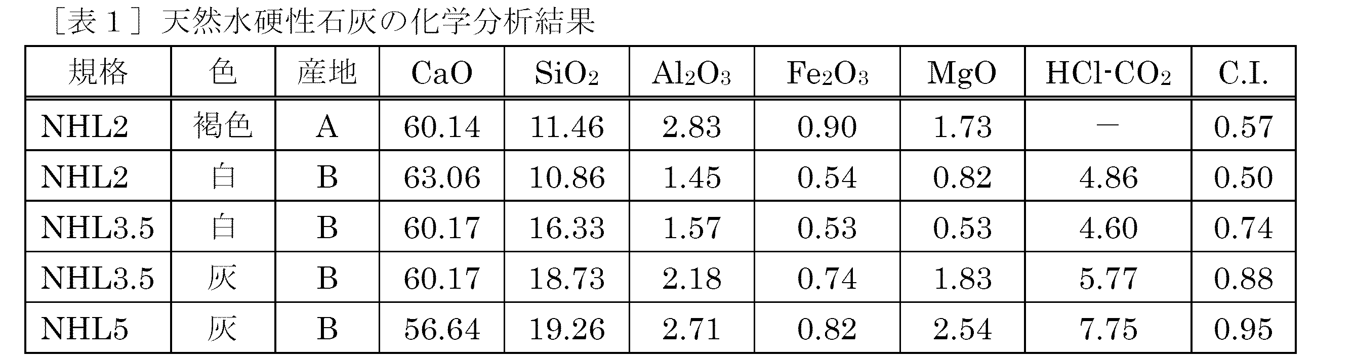 セメント係数C.I.が高い天然水硬性石灰ほど規定強度が高くなり、SiO2の割合も高くなっていることが分かる。天然水硬性石灰は歴史上、セメント発明の元となった石灰であり、水和成分を高めた材料である。セメントの化学成分は天然水硬性石灰とほぼ同等であるが、C2Sのほか、ケイ酸三カルシウム(3CaO・SiO2、エーライト、以下C3S)、カルシウムアルミネート(3CaO・Al2O3、アルミネート、以下C3A)、カルシウムアルミノフェライト(4CaO・Al2O3・Fe2O3、フェライト、以下C4AF)等のクリンカーおよび硫酸カルシウム(CaSO4・2H2O、セッコウ)が含まれる。
C3SとC2Sはいずれもケイ酸塩であり、両者をまとめて「シリケート相」と称する。また、C3AとC4AFはクリンカー中でシリケート相の間隙部に存在するため、まとめて「間隙相」と称する。それぞれのクリンカー鉱物は、水和反応速度、強さの発現性、水和熱などの性質が異なる。このような性質の異なるクリンカー鉱物の組成を変化させ、さらに、セッコウの添加量、セメントの粉末度(比表面積値)などを変化させることによって、物性の異なる種々のセメントを製造することができる。
クリンカーが天然水硬性石灰の水和物中に占める割合は極めて小さいこと、及びシリケート相のほとんどがC2Sであることが、天然水硬性石灰の化学的な特徴である。クリンカーの割合はNHL2で約10~25%、NHL3.5で約25~40%、NHL5では約40~50%である。NHL5の場合はC2SだけでなくC3Sも含まれる。
消石灰は主に水酸化カルシウムからなり、天然水硬性石灰と比較して、SiO2、Al2O3、Fe2O3、MgOといったいわゆる不純分が極めて少なく、水和反応は起こらない。
本実施形態において天然水硬性石灰は、粘土質または珪質石灰石(泥灰石、marlとも云う)の焼成によって得られる石灰を意味し、欧州規格においては「粉砕に関係なく消化によって粉末化した、いくらか粘土質または珪質の石灰石の焼成によって作られる石灰を意味する。すべてのNHLは水硬性を持つ。大気中の炭酸ガスは、硬化に寄与する。」と定義される。
天然水硬性石灰の主成分は、水酸化カルシウム(Ca(OH)2)、炭酸カルシウム(CaCO3)、ケイ酸二カルシウム(2CaO・SiO2、ビーライト、以下C2S)、二酸化ケイ素(SiO2)である。
化学分析結果は表1に示すとおり、CaOが60%程度、水硬性に起因するSiO2は10~20%である。表1のセメント係数C.I.(Cementation Index)は水硬性の度合いを示す指標の一つであり、以下の式で計算される。
C3SとC2Sはいずれもケイ酸塩であり、両者をまとめて「シリケート相」と称する。また、C3AとC4AFはクリンカー中でシリケート相の間隙部に存在するため、まとめて「間隙相」と称する。それぞれのクリンカー鉱物は、水和反応速度、強さの発現性、水和熱などの性質が異なる。このような性質の異なるクリンカー鉱物の組成を変化させ、さらに、セッコウの添加量、セメントの粉末度(比表面積値)などを変化させることによって、物性の異なる種々のセメントを製造することができる。
クリンカーが天然水硬性石灰の水和物中に占める割合は極めて小さいこと、及びシリケート相のほとんどがC2Sであることが、天然水硬性石灰の化学的な特徴である。クリンカーの割合はNHL2で約10~25%、NHL3.5で約25~40%、NHL5では約40~50%である。NHL5の場合はC2SだけでなくC3Sも含まれる。
消石灰は主に水酸化カルシウムからなり、天然水硬性石灰と比較して、SiO2、Al2O3、Fe2O3、MgOといったいわゆる不純分が極めて少なく、水和反応は起こらない。
人工水硬性石灰
天然水硬性石灰に対して、人工水硬性石灰は、いわゆるローマンセメントあるいは古代セメントと呼ばれており、欧州規格EN459‐1において「水酸化カルシウム、珪酸カルシウム、アルミン酸カルシウムを主成分とし、これらの混合によって作られる石灰。水硬性を持つ。大気中の炭酸ガスは、硬化に寄与する。」と定義される。本実施形態において人工水硬性石灰とは、消石灰にポゾラン質(珪酸(SiO2)、アルミナ(Al2O3)、酸化鉄(Fe2O3)などの鉱物)を後から添加したものを意味し、天然水硬性石灰とは区別される。
天然水硬性石灰に対して、人工水硬性石灰は、いわゆるローマンセメントあるいは古代セメントと呼ばれており、欧州規格EN459‐1において「水酸化カルシウム、珪酸カルシウム、アルミン酸カルシウムを主成分とし、これらの混合によって作られる石灰。水硬性を持つ。大気中の炭酸ガスは、硬化に寄与する。」と定義される。本実施形態において人工水硬性石灰とは、消石灰にポゾラン質(珪酸(SiO2)、アルミナ(Al2O3)、酸化鉄(Fe2O3)などの鉱物)を後から添加したものを意味し、天然水硬性石灰とは区別される。
水硬性石灰の硬化メカニズム
石灰石(CaCO3、炭酸カルシウム)の焼成・消化によって得られる消石灰は、空気中の二酸化炭素(CO2)との結合(以下、炭酸化)によって、もとの石灰石に還元される性質を持つ。消石灰は気硬性の材料であり、水との混合による硬化後、生成されるCaCO3結晶同士は結合せず、強度は発現しない。
天然水硬性石灰は、SiO2などを含むケイ質の石灰石を焼成・消化することによって得られ、Ca(OH)2を主成分として、C2Sなどの水和物を含む石灰である。水との接触で、水和物はCa(OH)2の結晶を結合し、さらに炭酸化によりCa(OH)2は表層面から次第にCaCO3結晶へと変化する。CaCO3結晶は水和物によって結合状態を保っており、その水和物は同じ炭酸化作用によってCaCO3結晶へと変化(炭酸カルシウム結晶化)する。
表層が炭酸化すると、CaCO3結晶は空隙を含んだ粒状構造を形成し、奥のCa(OH)2に空気中の炭酸ガスが供給され、炭酸化が緩やかに進行する。
すなわち天然水硬性石灰は、水硬性・気硬性を併せ持つ材料であり、水との混合により硬化後、強度を発現する。その強度は欧州規格EN459‐1に規定されるとおりである。
図1に、水硬性石灰の硬化メカニズムの概念図を示す。
石灰石(CaCO3、炭酸カルシウム)の焼成・消化によって得られる消石灰は、空気中の二酸化炭素(CO2)との結合(以下、炭酸化)によって、もとの石灰石に還元される性質を持つ。消石灰は気硬性の材料であり、水との混合による硬化後、生成されるCaCO3結晶同士は結合せず、強度は発現しない。
天然水硬性石灰は、SiO2などを含むケイ質の石灰石を焼成・消化することによって得られ、Ca(OH)2を主成分として、C2Sなどの水和物を含む石灰である。水との接触で、水和物はCa(OH)2の結晶を結合し、さらに炭酸化によりCa(OH)2は表層面から次第にCaCO3結晶へと変化する。CaCO3結晶は水和物によって結合状態を保っており、その水和物は同じ炭酸化作用によってCaCO3結晶へと変化(炭酸カルシウム結晶化)する。
表層が炭酸化すると、CaCO3結晶は空隙を含んだ粒状構造を形成し、奥のCa(OH)2に空気中の炭酸ガスが供給され、炭酸化が緩やかに進行する。
すなわち天然水硬性石灰は、水硬性・気硬性を併せ持つ材料であり、水との混合により硬化後、強度を発現する。その強度は欧州規格EN459‐1に規定されるとおりである。
図1に、水硬性石灰の硬化メカニズムの概念図を示す。
水硬性石灰は、圧縮強さによって、欧州規格EN459‐1に規定される次の3種類に区分することができる(水中養生による28日強度)。
HL2、NHL2 2~7 N/mm2
HL3.5、NHL3.5 3.5~10 N/mm2
HL5、NHL5 5~15 N/mm2
HL2、NHL2 2~7 N/mm2
HL3.5、NHL3.5 3.5~10 N/mm2
HL5、NHL5 5~15 N/mm2
本発明の一実施形態において、NHL2、NHL3.5、NHL5、HL2、HL3.5、HL5等の水硬性石灰を用いることができるが、これらに限定されるものではない。天然水硬性石灰は産地によって、成分に多少のばらつきがあるがCa(OH)2、CaCO3、C2S、SiO2を主成分とするものであればよい。天然水硬性石灰はフランス産のものが有名であるが、チュニジア産、イタリア産等、他の産地のものであってもよい。水硬性石灰は、セメント係数0.45~0.96を有するものが好ましく、0.5~0.88を有するものがより好ましく、0.5~0.75を有するものがさらに好ましい。セメント係数が0.45未満、あるいは0.96を超える場合は、炭酸ガス養生による強度発現の効果は、それほど高くはない。
ある実施形態において、水硬性石灰及び水を含む混合物は、水硬性石灰に対して5~15質量%の水分を含有することが好ましい。
水硬性石灰と混合する水は、炭酸ガスを溶解させた水を使用してもよい。
水硬性石灰と混合する水は、炭酸ガスを溶解させた水を使用してもよい。
(プレス成形)
プレス成形(圧縮成形)とは、加工機械および型、工具等を用いて、材料に圧縮等の変形を与えて成形体を得る方法であるが、その成形形態として絞り、深絞り、フランジ、コールゲート、エッジカーリング、型打ちなどが例示される。また、本発明の一実施形態におけるプレス成形の方法として、型を用いて成形を行う金型プレス法、ラバープレス法(静水圧成形法)、ローラー成形法、押出成形法、鋳込み成形法等を用いることができる。上記プレス成形の方法のなかでも、成形圧力の観点から、金属製の型を用いて成形を行なってもよい。
本実施形態において、プレス成形の圧力は、5N/mm2以上であれば曲げ強さが改善されるが、10N/mm2以上が好ましく、15N/mm2以上がより好ましく、30N/mm2以上がさらに好ましい。
プレス成形(圧縮成形)とは、加工機械および型、工具等を用いて、材料に圧縮等の変形を与えて成形体を得る方法であるが、その成形形態として絞り、深絞り、フランジ、コールゲート、エッジカーリング、型打ちなどが例示される。また、本発明の一実施形態におけるプレス成形の方法として、型を用いて成形を行う金型プレス法、ラバープレス法(静水圧成形法)、ローラー成形法、押出成形法、鋳込み成形法等を用いることができる。上記プレス成形の方法のなかでも、成形圧力の観点から、金属製の型を用いて成形を行なってもよい。
本実施形態において、プレス成形の圧力は、5N/mm2以上であれば曲げ強さが改善されるが、10N/mm2以上が好ましく、15N/mm2以上がより好ましく、30N/mm2以上がさらに好ましい。
(プレス成形体)
本実施形態において、プレス成形体とは、水硬性石灰及び水を含む混合物をプレス成形して得られた成形体を意味する。
本実施形態において、プレス成形体とは、水硬性石灰及び水を含む混合物をプレス成形して得られた成形体を意味する。
(骨材)
ある実施形態において、混合物は、さらに骨材を含んでもよい。本実施形態で使用する骨材として、天然骨材、人工骨材、及び再生骨材を使用することができるが、これらに限定されるものではない。天然骨材の例としては、川砂、川砂利、山砂、山砂利、炭酸カルシウム、ゼオライト、バーミキュライト、珪藻土等がある。人工骨材の例としては、高炉スラグ骨材、フライアッシュなどを高温焼成した人工軽量骨材がある。再生骨材の例としては、コンクリート廃材から取り出した骨材や廃ガラスなどがある。セメントの骨材として使用されるセメント強さ試験用標準砂(JIS R 5201)、5号ケイ砂、6号ケイ砂及び8号ケイ砂を骨材として使用してもよく、消石灰を用いることもできる。使用する骨材と水硬性石灰の種類に応じて、骨材と水硬性石灰の配合比を調節することによって強度発現を改善することができる。
骨材を使用する場合、水硬性石灰に対する骨材の配合比率は、水硬性石灰:骨材として1:4未満の質量比で配合されることが好ましく、1:1から1:3がより好ましく、1:1から1:2がさらに好ましい。
骨材の粒度は、最大径が5mm以下のものが好ましく、1mm以下のものがより好ましく、150μm以下のものがさらに好ましい。
また、骨材の粒度分布のピーク値は、30~1000μmのものが好ましく、30~500μmのものがより好ましく、30~150μmのものがさらに好ましい。
ある実施形態において、混合物は、さらに骨材を含んでもよい。本実施形態で使用する骨材として、天然骨材、人工骨材、及び再生骨材を使用することができるが、これらに限定されるものではない。天然骨材の例としては、川砂、川砂利、山砂、山砂利、炭酸カルシウム、ゼオライト、バーミキュライト、珪藻土等がある。人工骨材の例としては、高炉スラグ骨材、フライアッシュなどを高温焼成した人工軽量骨材がある。再生骨材の例としては、コンクリート廃材から取り出した骨材や廃ガラスなどがある。セメントの骨材として使用されるセメント強さ試験用標準砂(JIS R 5201)、5号ケイ砂、6号ケイ砂及び8号ケイ砂を骨材として使用してもよく、消石灰を用いることもできる。使用する骨材と水硬性石灰の種類に応じて、骨材と水硬性石灰の配合比を調節することによって強度発現を改善することができる。
骨材を使用する場合、水硬性石灰に対する骨材の配合比率は、水硬性石灰:骨材として1:4未満の質量比で配合されることが好ましく、1:1から1:3がより好ましく、1:1から1:2がさらに好ましい。
骨材の粒度は、最大径が5mm以下のものが好ましく、1mm以下のものがより好ましく、150μm以下のものがさらに好ましい。
また、骨材の粒度分布のピーク値は、30~1000μmのものが好ましく、30~500μmのものがより好ましく、30~150μmのものがさらに好ましい。
(その他の成分)
また、ある実施形態において、混合物は、内部に格子状、網状あるいは軸状の強化材を含むことができる。格子状、網状あるいは軸状の強化材は、鉄などの金属製、樹脂製、ガラス繊維製、カーボンファイバー、植物繊維の物を使用することができるが、これに限定されない。
また、ある実施形態において、混合物は、内部に格子状、網状あるいは軸状の強化材を含むことができる。格子状、網状あるいは軸状の強化材は、鉄などの金属製、樹脂製、ガラス繊維製、カーボンファイバー、植物繊維の物を使用することができるが、これに限定されない。
また、本実施形態の成形体の製造方法は、加熱工程を必要としないことから、混合物中に様々な成分を含有させることもできる。含有させる成分として、パルプ、すさなどの植物繊維、アラビアガム、天然ゴム、カゼイン、セルロースなどの天然樹脂、アクリル、酢酸ビニルなどの合成樹脂類、炭素繊維や炭などの炭素系素材、亜鉛、インジウム、ガリウム、スズ、ビスマス、鉛、金、銀、プラチナなど低融点の金属あるいはこれらによる合金または化合物等が挙げられる。例えば炭素系素材などの吸着材を含有させることにより、脱臭作用を有する成形体が得られる。また、顔料や染料などを加えて着色をすることができる。
[炭酸ガス養生工程]
本実施形態における製造方法は、プレス成形体を炭酸ガス養生に供する工程を含む製造方法である。
炭酸ガス養生の期間は、水硬性石灰及び水を含む混合物のプレス成形体が、硬化するための必要十分な期間である。本発明の一実施形態において、その期間は、成形体の大きさ、周囲環境温度及び湿度などにより異なるが、一般的には、2日間以上であることが望ましく、3日間以上であることがより望ましく、7日間以上であることがさらに望ましい。
本実施形態において、プレス成形体は型枠で拘束されておらず、解放面が多いことから、型枠に拘束した状態での炭酸ガス養生よりも硬化するために必要な期間が短縮される。
本実施形態における製造方法は、プレス成形体を炭酸ガス養生に供する工程を含む製造方法である。
炭酸ガス養生の期間は、水硬性石灰及び水を含む混合物のプレス成形体が、硬化するための必要十分な期間である。本発明の一実施形態において、その期間は、成形体の大きさ、周囲環境温度及び湿度などにより異なるが、一般的には、2日間以上であることが望ましく、3日間以上であることがより望ましく、7日間以上であることがさらに望ましい。
本実施形態において、プレス成形体は型枠で拘束されておらず、解放面が多いことから、型枠に拘束した状態での炭酸ガス養生よりも硬化するために必要な期間が短縮される。
炭酸ガス養生の炭酸ガス濃度は、大気中濃度(およそ0.03%)よりも高いほど強度発現の効果が期待でき、例えば、1容積%以上あることが望ましい。5容積%以上の炭酸ガス養生で高強度を早期に発現させることができ、10容積%や20容積%のようなより高濃度の炭酸ガス養生に供することで、より早期に高強度を発現させることができる。
炭酸ガス養生は、製造する建材の大きさや周辺環境によって、養生の実施方法を調節することができる。例えば、100×100×10mmのプレス成形体を使用する場合は、プレス成形体を炭酸ガス養生室の棚に配置した後、扉を閉めて内部を密閉状態にする。その後、養生室の空気を一旦脱気した後に、所望の濃度まで二酸化炭素を注入する。所望の二酸化炭素濃度を維持するため、自動で又は手動で適宜二酸化炭素を注入する。炭酸ガス養生釜を用いる場合には、加圧環境下で行うこともできる。建設現場で打設する場合には、プレス成形体の周囲に仮設の炭酸ガス養生室を設置して、炭酸ガスを注入することができる。
本実施形態の製造方法で製造された水硬性石灰を含む成形体の曲げ強さは、両端支持とし中央部を載荷した曲げ試験により試験片が破壊に至るまでの最大モーメントを、試験片の断面係数で割ることにより算出した曲げ応力の値である。本実施形態の製造方法により製造される成形体は、7.5N/mm2以上の曲げ強さ、より好ましくは8N/mm2以上の曲げ強さを有することを特徴とする。他の実施形態にかかる方法では、プレス圧力、骨材の粒度及び配合比、炭酸ガス養生条件を調節することにより、10N/mm2以上、また19N/mm2以上、さらには23N/mm2以上の曲げ強さを有する水硬性石灰を含む成形体を製造することが可能である。
また、本実施形態の炭酸カルシウム結晶化された水硬性石灰を含む成形体は、好ましくは1.5g/cm3以上、より好ましくは1.65g/cm3以上、さらに好ましくは1.7g/cm3以上、特に好ましくは1.9g/cm3以上の密度を有する。
また、本実施形態の炭酸カルシウム結晶化された水硬性石灰を含む成形体は、好ましくは1.5g/cm3以上、より好ましくは1.65g/cm3以上、さらに好ましくは1.7g/cm3以上、特に好ましくは1.9g/cm3以上の密度を有する。
[部材]
本発明の一実施形態における水硬性石灰を含む成形体は、加工することにより部材として用いることができる。部材としては、タイル、パネル、ボード等の建築部材、食器、生活用品、機械部品、電気器具等が挙げられる。
本発明の一実施形態における水硬性石灰を含む成形体は、加工することにより部材として用いることができる。部材としては、タイル、パネル、ボード等の建築部材、食器、生活用品、機械部品、電気器具等が挙げられる。
[実施例1]
1.試験体の作製
1.1.材料
(天然水硬性石灰)
試験体の作製に使用した水硬性石灰は、A産地(フランス東部)のNHL2であり、これらの化学成分は表1に示す通りである。
(骨材)
試験体の作製に、骨材として、粒度分布の異なる5号ケイ砂(三河珪砂)、6号ケイ砂(三河珪砂)、8号ケイ砂(三河珪砂)及び最大径250μm以下で粒度分布のピーク値が40~100μmである炭酸カルシウム(常陸砕石)を使用した。
1.試験体の作製
1.1.材料
(天然水硬性石灰)
試験体の作製に使用した水硬性石灰は、A産地(フランス東部)のNHL2であり、これらの化学成分は表1に示す通りである。
(骨材)
試験体の作製に、骨材として、粒度分布の異なる5号ケイ砂(三河珪砂)、6号ケイ砂(三河珪砂)、8号ケイ砂(三河珪砂)及び最大径250μm以下で粒度分布のピーク値が40~100μmである炭酸カルシウム(常陸砕石)を使用した。
1.2.試験体の各成分の配合量
表2に、製造した試験体のパラメータを示す。
(水分量)
欧州規格EN459‐2の規定に従って水硬性石灰に対して55質量%の水分量を加えてプレス成形したところ、プレス成形体が得られなかったことから、試験体作製時に混合する水分量は、水硬性石灰に対して10質量%とした。
型枠内で養生する非圧縮成形の試験体については、欧州規格EN459‐2に規定される通り、水硬性石灰に対して55質量%の水分量を加えた。
(骨材)
試験体作製時の骨材の配合量は、水硬性石灰に対して1:1、1:2及び1:4とした。
表2に、製造した試験体のパラメータを示す。
(水分量)
欧州規格EN459‐2の規定に従って水硬性石灰に対して55質量%の水分量を加えてプレス成形したところ、プレス成形体が得られなかったことから、試験体作製時に混合する水分量は、水硬性石灰に対して10質量%とした。
型枠内で養生する非圧縮成形の試験体については、欧州規格EN459‐2に規定される通り、水硬性石灰に対して55質量%の水分量を加えた。
(骨材)
試験体作製時の骨材の配合量は、水硬性石灰に対して1:1、1:2及び1:4とした。
1.3.試験体の製造工程
(プレス成形条件)
プレス成形は、粉末成型プレスを用いて、0N/mm2(非圧縮)、10N/mm2、20N/mm2、40N/mm2の圧力で行い、100×100×10mmのプレス成形体を得た。
(プレス成形条件)
プレス成形は、粉末成型プレスを用いて、0N/mm2(非圧縮)、10N/mm2、20N/mm2、40N/mm2の圧力で行い、100×100×10mmのプレス成形体を得た。
(養生条件)
養生条件は、気中養生(実施中)(温度20±1℃、相対湿度60±5%)、炭酸ガス養生(温度20±1℃、相対湿度60±5%、炭酸ガス濃度5%)の2種類で試験を行った。
非圧縮成型の試験体の養生条件は、特許文献1を参照して、2日水中養生(型枠をプラスチック板により2日密閉)したものを脱型後に炭酸ガス養生したもの、及び、開放型に設置したまま炭酸ガス養生し、7日後に脱型し再び炭酸ガス養生したものの2種類の方法によって行った。

養生条件は、気中養生(実施中)(温度20±1℃、相対湿度60±5%)、炭酸ガス養生(温度20±1℃、相対湿度60±5%、炭酸ガス濃度5%)の2種類で試験を行った。
非圧縮成型の試験体の養生条件は、特許文献1を参照して、2日水中養生(型枠をプラスチック板により2日密閉)したものを脱型後に炭酸ガス養生したもの、及び、開放型に設置したまま炭酸ガス養生し、7日後に脱型し再び炭酸ガス養生したものの2種類の方法によって行った。
2.試験体の曲げ強さの測定
(測定方法)
曲げ強さの測定試験は、100×100×10mmの試験体を作製して行った。試験体は、2体を1セットとして、曲げ強さを測定し、2体の平均値とした。測定は、20kN万能試験機(島津製作所製)を用いて行った。試験体の加力方法は万能試験機による3点支持の一方向単調加力とし、載荷スピードは最大強度を加味しながら1から10N/secに荷重制御して行った。
3点曲げによる曲げ強さは、以下の公式よって計算される。
ρ = 3PD/2bh2
ここで、ρは曲げ強さ(N/mm2)、Pは破壊荷重(N)、Dは支持支点距離(mm)、bh2は成形体の寸法(幅b(mm)、成h(mm))を表し、ここではDを90mmとした。
(測定方法)
曲げ強さの測定試験は、100×100×10mmの試験体を作製して行った。試験体は、2体を1セットとして、曲げ強さを測定し、2体の平均値とした。測定は、20kN万能試験機(島津製作所製)を用いて行った。試験体の加力方法は万能試験機による3点支持の一方向単調加力とし、載荷スピードは最大強度を加味しながら1から10N/secに荷重制御して行った。
3点曲げによる曲げ強さは、以下の公式よって計算される。
ρ = 3PD/2bh2
ここで、ρは曲げ強さ(N/mm2)、Pは破壊荷重(N)、Dは支持支点距離(mm)、bh2は成形体の寸法(幅b(mm)、成h(mm))を表し、ここではDを90mmとした。
3.測定試験結果
3.1.成形圧力と、水硬性石灰及び骨材の配合比率による影響
0N/mm2(非圧縮)、10N/mm2、20N/mm2、40N/mm2の圧力で成形プレスを実施し、プレス成形の圧力が曲げ強さに与える影響について検討した。また、水硬性石灰と骨材との配合比率を1:1、1:2、1:4とした場合について、水硬性石灰及び骨材の配合比率が曲げ強さに与える影響について検討した。
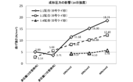
図2に示されるように、成形時の圧力は高いほど、曲げ強さは上昇することが明らかとなった。また、水硬性石灰に対する骨材の配合比率が高くなるほど曲げ強さは低下したが、水硬性石灰に対する骨材の配合比率が1:1及び1:2では、骨材配合による曲げ強さ低下の影響は抑制されることが明らかとなった。
8号ケイ砂を水硬性石灰との配合比で1:1とし、成形圧力が40N/mm2の場合、炭酸ガス養生28日で曲げ強さ19.47N/mm2が得られた(図2)。この値は、非圧縮の7日型枠内の28日目の結果(28日強度:3~5N/mm2)の約4倍の強度であった。この結果から、型枠による拘束に対し、成型時に圧力をかける場合の方が、より高い強度の発現を促すことが明らかとなった。
3.1.成形圧力と、水硬性石灰及び骨材の配合比率による影響
0N/mm2(非圧縮)、10N/mm2、20N/mm2、40N/mm2の圧力で成形プレスを実施し、プレス成形の圧力が曲げ強さに与える影響について検討した。また、水硬性石灰と骨材との配合比率を1:1、1:2、1:4とした場合について、水硬性石灰及び骨材の配合比率が曲げ強さに与える影響について検討した。
図2に示されるように、成形時の圧力は高いほど、曲げ強さは上昇することが明らかとなった。また、水硬性石灰に対する骨材の配合比率が高くなるほど曲げ強さは低下したが、水硬性石灰に対する骨材の配合比率が1:1及び1:2では、骨材配合による曲げ強さ低下の影響は抑制されることが明らかとなった。
8号ケイ砂を水硬性石灰との配合比で1:1とし、成形圧力が40N/mm2の場合、炭酸ガス養生28日で曲げ強さ19.47N/mm2が得られた(図2)。この値は、非圧縮の7日型枠内の28日目の結果(28日強度:3~5N/mm2)の約4倍の強度であった。この結果から、型枠による拘束に対し、成型時に圧力をかける場合の方が、より高い強度の発現を促すことが明らかとなった。
3.2.養生条件による影響
5容積%の炭酸ガスを用いて、3日間、7日間、14日間、21日間、28日間の炭酸ガス養生又は気中養生を実施し、炭酸ガス養生日数が曲げ強さに与える影響について検討した。
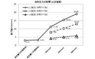
図3に示されるように、成形圧力40N/mm2の場合、8号ケイ砂を配合比1:1とした時に曲げ強さ19.47N/mm2が得られた。この値は、気中養生で得られた試験結果(成形圧力、配合や養生期間など同条件で製作した場合3.62N/mm2)のおよそ5倍となり、炭酸養生することにより約5倍まで曲げ強さを上昇できることが確認できる。
骨材として炭酸カルシウムを用いた場合(図4)の結果から解るように、成形圧力が40N/mm2の場合を除き、養生期間3日で最大強度を発現している。一方、成形圧力が40N/mm2の場合、7日で最大強度を発現した。このことから、成形時の圧縮力が上がると結晶間距離が縮まり、炭酸ガスが通りにくくなることで強度を発現するまでに時間が必要となることが考えられる。
なお、試験後断面のフェノールフタレインによるアルカリ残分の確認により、少なくとも7日間の炭酸ガス養生により、炭酸化は全面的に進行していることが確認されている。
一方、気中養生した場合、曲げ強さが2N/mm2以下であったことから、炭酸ガス養生が強度上昇へ影響することが確認できる。
5容積%の炭酸ガスを用いて、3日間、7日間、14日間、21日間、28日間の炭酸ガス養生又は気中養生を実施し、炭酸ガス養生日数が曲げ強さに与える影響について検討した。
図3に示されるように、成形圧力40N/mm2の場合、8号ケイ砂を配合比1:1とした時に曲げ強さ19.47N/mm2が得られた。この値は、気中養生で得られた試験結果(成形圧力、配合や養生期間など同条件で製作した場合3.62N/mm2)のおよそ5倍となり、炭酸養生することにより約5倍まで曲げ強さを上昇できることが確認できる。
骨材として炭酸カルシウムを用いた場合(図4)の結果から解るように、成形圧力が40N/mm2の場合を除き、養生期間3日で最大強度を発現している。一方、成形圧力が40N/mm2の場合、7日で最大強度を発現した。このことから、成形時の圧縮力が上がると結晶間距離が縮まり、炭酸ガスが通りにくくなることで強度を発現するまでに時間が必要となることが考えられる。
なお、試験後断面のフェノールフタレインによるアルカリ残分の確認により、少なくとも7日間の炭酸ガス養生により、炭酸化は全面的に進行していることが確認されている。
一方、気中養生した場合、曲げ強さが2N/mm2以下であったことから、炭酸ガス養生が強度上昇へ影響することが確認できる。
3.3.骨材の粒度による影響
水硬性石灰と骨材との配合比率1:2、成型圧力10N/mm2の条件下で、8号ケイ砂、6号ケイ砂、5号ケイ砂の3種類を比較することにより、水硬性石灰と混合する骨材の粒度が曲げ強さに与える影響について検討した。
図5に示されるように、骨材粒度の影響は小さいものの、粒度の細かい8号ケイ砂で強度が最も高くなる傾向が示された。
また骨材の種類による影響については、骨材を炭酸カルシウムとした場合と8号ケイ砂とした場合、水硬性石灰と骨材との配合比率1:1および1:2、成型圧力40N/mm2の結果が同等となっていることが解る。炭酸カルシウムは粒度特性上ピーク値が40~100μm付近と8号ケイ砂と近いことから、骨材の種類による影響は小さく、骨材の粒度特性が強度発現に影響していることが確認できる。
水硬性石灰と骨材との配合比率1:2、成型圧力10N/mm2の条件下で、8号ケイ砂、6号ケイ砂、5号ケイ砂の3種類を比較することにより、水硬性石灰と混合する骨材の粒度が曲げ強さに与える影響について検討した。
図5に示されるように、骨材粒度の影響は小さいものの、粒度の細かい8号ケイ砂で強度が最も高くなる傾向が示された。
また骨材の種類による影響については、骨材を炭酸カルシウムとした場合と8号ケイ砂とした場合、水硬性石灰と骨材との配合比率1:1および1:2、成型圧力40N/mm2の結果が同等となっていることが解る。炭酸カルシウムは粒度特性上ピーク値が40~100μm付近と8号ケイ砂と近いことから、骨材の種類による影響は小さく、骨材の粒度特性が強度発現に影響していることが確認できる。
[実施例2]
1.試験体の作製
実施例1で用いた材料を用いて、適宜水分量を調節し、実施例1と同等寸法の試験体を製造し、成形圧力、炭酸ガスの養生濃度および水硬性石灰と混合する骨材の有無の影響について補足するため再度曲げ試験を行った。表3に、製造した試験体のパラメータを示す。
実施例1で与えた10~40N/mm2の成形圧力に対して、実施例2では下限を5N/mm2、上限を60N/mm2として、成形圧力の影響について検討を行った。
養生条件としては、炭酸濃度1%についても実施した。ただし、濃度1%については、養生期間を2日とした場合のみ実施した。養生期間については、実施例1において、14日以上で顕著な上昇が見られなかったことから、最大養生期間日数を14日とした。
配合骨材は、実施例1で骨材の種類についての影響は小さいとの結果に基づいて、実施例1で使用した40~100μmを粒度分布のピーク値とする常盤砕石の炭酸カルシウム骨材を再度使用した。さらに、骨材を含まない水硬性石灰のみとした試験体についても試験した。
成形は、3000kN万能試験機(INSTRON製)を用いて、成形圧力が3軸方向等圧となるよう圧縮して行い、試験体形状は実施例1と同様に100×100×10mmとした。
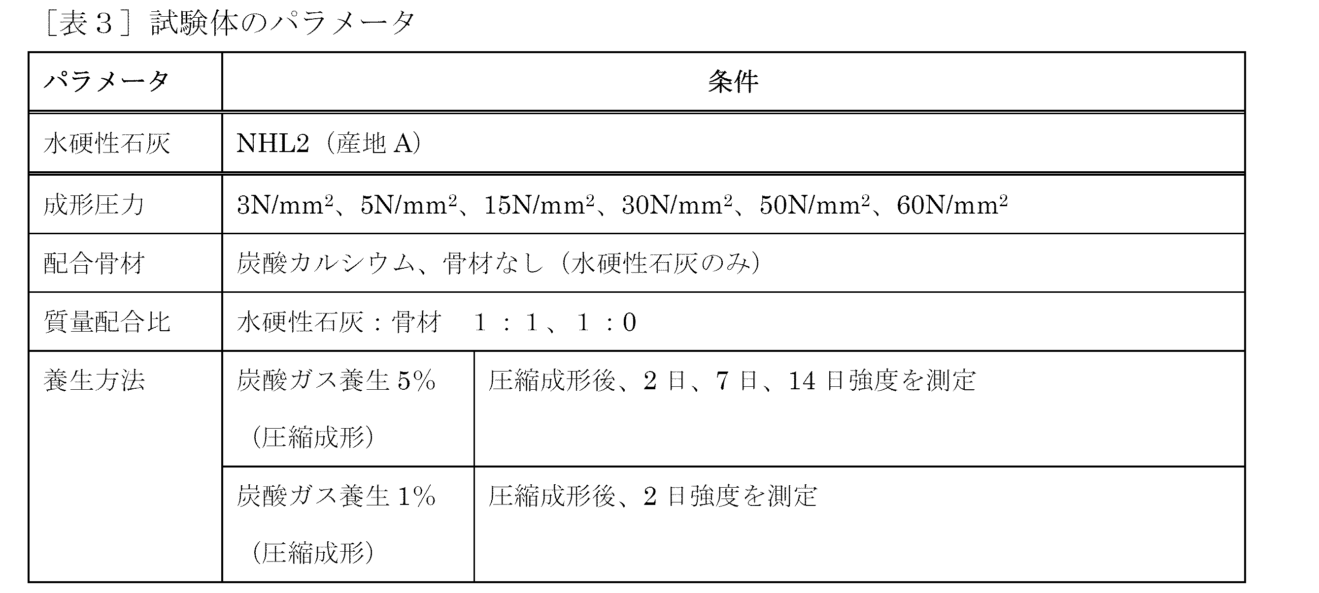
1.試験体の作製
実施例1で用いた材料を用いて、適宜水分量を調節し、実施例1と同等寸法の試験体を製造し、成形圧力、炭酸ガスの養生濃度および水硬性石灰と混合する骨材の有無の影響について補足するため再度曲げ試験を行った。表3に、製造した試験体のパラメータを示す。
実施例1で与えた10~40N/mm2の成形圧力に対して、実施例2では下限を5N/mm2、上限を60N/mm2として、成形圧力の影響について検討を行った。
養生条件としては、炭酸濃度1%についても実施した。ただし、濃度1%については、養生期間を2日とした場合のみ実施した。養生期間については、実施例1において、14日以上で顕著な上昇が見られなかったことから、最大養生期間日数を14日とした。
配合骨材は、実施例1で骨材の種類についての影響は小さいとの結果に基づいて、実施例1で使用した40~100μmを粒度分布のピーク値とする常盤砕石の炭酸カルシウム骨材を再度使用した。さらに、骨材を含まない水硬性石灰のみとした試験体についても試験した。
成形は、3000kN万能試験機(INSTRON製)を用いて、成形圧力が3軸方向等圧となるよう圧縮して行い、試験体形状は実施例1と同様に100×100×10mmとした。
2.試験体の測定
2.1.試験体の曲げ強さの測定
曲げ強さの測定試験は、実施例1と同様に100×100×10mmの試験体を作製して行った。試験体数は3体とし、これら平均を試験結果の値とした。加力方法は、100kN万能試験機(島津製作所製)による3点支持の一方向単調加力とし、載荷スピードは10N/secに荷重制御して行った。3点曲げによる曲げ強さは、実施例1と同様の公式によって計算した。
2.1.試験体の曲げ強さの測定
曲げ強さの測定試験は、実施例1と同様に100×100×10mmの試験体を作製して行った。試験体数は3体とし、これら平均を試験結果の値とした。加力方法は、100kN万能試験機(島津製作所製)による3点支持の一方向単調加力とし、載荷スピードは10N/secに荷重制御して行った。3点曲げによる曲げ強さは、実施例1と同様の公式によって計算した。
3.測定試験結果
3.1.成形圧力および養生期間の影響
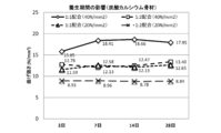
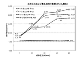
図7に骨材(炭酸カルシウム)を水硬性石灰に対して1:1で配合し、炭酸濃度を5%で養生した場合の成形圧力-曲げ強さ関係の試験結果を示す。
成形圧力が高くなるにつれて、養生期間の長い試験体ほど曲げ強さがやや高くなる傾向となったが、2日養生を供することで7日養生にほぼ近い値を示すことが確認された。また、7日以上の養生期間で、成形圧力を上げることにより、実施例1の結果を上回る20N/mm2以上の高い曲げ強さが得られた。
成形圧力が低くなるにつれ、養生期間の影響は小さくなり、例えば5N/mm2では、最も短い2日養生の場合、曲げ強さは7.79N/mm2となった。この5N/mm2、2日養生の場合の曲げ強さの値は、特許文献1に記載される非圧縮・型枠内成形(以下、非圧縮成形)の試験体で実施した結果の最大曲げ荷重である5.66N/mm2の約1.5倍であり、成形圧力を5N/mm2以上とすることで、非圧縮成形の場合よりも曲げ強さが十分に改善されることが示された。
ここで、JIS A 5209セラミックタイル(5.1.6 曲げ破壊荷重)で規定される屋内床・浴室床の曲げ破壊荷重は540N以上と規定されており、寸法100×100×10mmでは曲げ強さに換算すると7.53N/mm2に相当する。それに対し、5N/mm2、2日養生の場合の曲げ強さの値は7.79N/mm2であり、上記の規定値を満足する値であった。
3.1.成形圧力および養生期間の影響
図7に骨材(炭酸カルシウム)を水硬性石灰に対して1:1で配合し、炭酸濃度を5%で養生した場合の成形圧力-曲げ強さ関係の試験結果を示す。
成形圧力が高くなるにつれて、養生期間の長い試験体ほど曲げ強さがやや高くなる傾向となったが、2日養生を供することで7日養生にほぼ近い値を示すことが確認された。また、7日以上の養生期間で、成形圧力を上げることにより、実施例1の結果を上回る20N/mm2以上の高い曲げ強さが得られた。
成形圧力が低くなるにつれ、養生期間の影響は小さくなり、例えば5N/mm2では、最も短い2日養生の場合、曲げ強さは7.79N/mm2となった。この5N/mm2、2日養生の場合の曲げ強さの値は、特許文献1に記載される非圧縮・型枠内成形(以下、非圧縮成形)の試験体で実施した結果の最大曲げ荷重である5.66N/mm2の約1.5倍であり、成形圧力を5N/mm2以上とすることで、非圧縮成形の場合よりも曲げ強さが十分に改善されることが示された。
ここで、JIS A 5209セラミックタイル(5.1.6 曲げ破壊荷重)で規定される屋内床・浴室床の曲げ破壊荷重は540N以上と規定されており、寸法100×100×10mmでは曲げ強さに換算すると7.53N/mm2に相当する。それに対し、5N/mm2、2日養生の場合の曲げ強さの値は7.79N/mm2であり、上記の規定値を満足する値であった。
3.2.養生炭酸濃度および成形圧力の影響
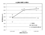
図8に、水硬性石灰と炭酸カルシウム炭酸骨材の配合比1:1とし、炭酸養生濃度を1%としたときの成形圧力3N/mm2および5N/mm2における曲げ強さを示す。比較として、炭酸養生濃度を5%とし、成形圧力5N/mm2とした場合の結果(図7に示したもの)を示すが、同じ成形圧力では、炭酸濃度1%の場合においても炭酸濃度5%の場合と同等かやや小さい曲げ強さであった。この炭酸濃度1%の場合の曲げ強さの平均は、8.13N/mm2であり、非圧縮成形の場合の最大値5.66N/mm2の1.4倍であり、炭酸濃度5%の場合と同等の値であった。
炭酸養生濃度1%、成形圧力を3N/mm2の場合の曲げ強さは、非圧縮成形の場合の曲げ強さを下回る結果であったことから、成形圧力を5N/mm2以上とすることで十分な曲げ強さが得られることが明らかとなった。さらに、成形圧力3N/mm2では、成形直後の強度不足により、移動作業におけるハンドリング性能が低下した。
以上の結果より、成形圧力5N/mm2および炭酸養生濃度1%以上とすることにより、非圧縮成形よりも高い曲げ強さが得られ、製作および使用環境において実用的な成形物を作成することが可能となることが明らかとなった。
図8に、水硬性石灰と炭酸カルシウム炭酸骨材の配合比1:1とし、炭酸養生濃度を1%としたときの成形圧力3N/mm2および5N/mm2における曲げ強さを示す。比較として、炭酸養生濃度を5%とし、成形圧力5N/mm2とした場合の結果(図7に示したもの)を示すが、同じ成形圧力では、炭酸濃度1%の場合においても炭酸濃度5%の場合と同等かやや小さい曲げ強さであった。この炭酸濃度1%の場合の曲げ強さの平均は、8.13N/mm2であり、非圧縮成形の場合の最大値5.66N/mm2の1.4倍であり、炭酸濃度5%の場合と同等の値であった。
炭酸養生濃度1%、成形圧力を3N/mm2の場合の曲げ強さは、非圧縮成形の場合の曲げ強さを下回る結果であったことから、成形圧力を5N/mm2以上とすることで十分な曲げ強さが得られることが明らかとなった。さらに、成形圧力3N/mm2では、成形直後の強度不足により、移動作業におけるハンドリング性能が低下した。
以上の結果より、成形圧力5N/mm2および炭酸養生濃度1%以上とすることにより、非圧縮成形よりも高い曲げ強さが得られ、製作および使用環境において実用的な成形物を作成することが可能となることが明らかとなった。
3.3.水硬性石灰のみとした場合の試験結果
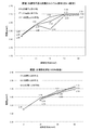
図9に、骨材を配合せず、水硬性石灰のみを用いて成形した場合についての成形圧力と曲げ強さとの関係を示す。成形圧力は、15、30、50N/mm2の範囲で実施した。
図9に示す通り、水硬性石灰のみを用いて成形した場合、炭酸カルシウム骨材を含む場合と同等またはこれをやや上回る曲げ強さを示した。
したがって、配合骨材の配合比率を大きく低減し、水硬性石灰のみとした場合も、曲げ強さに大きな影響を与えず、成形圧力を加えることで炭酸化により高い曲げ強さを発現できることが明らかとなった。
図9に、骨材を配合せず、水硬性石灰のみを用いて成形した場合についての成形圧力と曲げ強さとの関係を示す。成形圧力は、15、30、50N/mm2の範囲で実施した。
図9に示す通り、水硬性石灰のみを用いて成形した場合、炭酸カルシウム骨材を含む場合と同等またはこれをやや上回る曲げ強さを示した。
したがって、配合骨材の配合比率を大きく低減し、水硬性石灰のみとした場合も、曲げ強さに大きな影響を与えず、成形圧力を加えることで炭酸化により高い曲げ強さを発現できることが明らかとなった。
3.4.試験体の密度の測定結果
炭酸濃度5%の条件で、水硬性石灰と炭酸カルシウム骨材との配合比率1:1で製造した成形体及び水硬性石灰(骨材なし)で製造した成形体の密度を測定した結果を図10に示す。
骨材を炭酸カルシウム(配合1:1)、成形圧力を5N/mm2とした場合に1.68g/cm3という値が得られた。
骨材を含まない水硬性石灰のみを配合した場合、成形圧力5N/mm2、炭酸養生2日間の場合、1.5g/cm3であった。
炭酸濃度5%の条件で、水硬性石灰と炭酸カルシウム骨材との配合比率1:1で製造した成形体及び水硬性石灰(骨材なし)で製造した成形体の密度を測定した結果を図10に示す。
骨材を炭酸カルシウム(配合1:1)、成形圧力を5N/mm2とした場合に1.68g/cm3という値が得られた。
骨材を含まない水硬性石灰のみを配合した場合、成形圧力5N/mm2、炭酸養生2日間の場合、1.5g/cm3であった。
3.5.炭酸カルシウム結晶化の進行度合いの影響
炭酸カルシウム結晶化の進行度合いと曲げ強さの関係について、成形体の断面にフェノールフタレイン溶液を塗布して観察することにより確認した。成形圧力15N/mm2で製造した試験体において、2日間の炭酸養生により炭酸カルシウム結晶化は全面に進行していた。また、15N/mm2以下の成形圧力で製造した試験体においても同様に、骨材の配合比に関係なく炭酸カルシウム結晶化が進行しており、炭酸濃度が低い場合(1容積%)でも炭酸化はほぼ全面(断面の少なくとも90%)に進行することが確認された。
一般的に、高い成形圧力で製造した骨材を含まない成形体では炭酸カルシウム結晶化の進行は遅くなることが考えられることから、成形圧力50N/mm2、骨材なしで製造した試験体の炭酸カルシウム結晶化の進行度合いを確認した。その結果、表面から内側に少なくとも3mmの水硬性石灰が炭酸カルシウム結晶化していることが観察され、炭酸カルシウム結晶化の進行が表面から3mm程度進行した成形体でも強度を発現することが明らかとなった。
炭酸カルシウム結晶化の進行度合いと曲げ強さの関係について、成形体の断面にフェノールフタレイン溶液を塗布して観察することにより確認した。成形圧力15N/mm2で製造した試験体において、2日間の炭酸養生により炭酸カルシウム結晶化は全面に進行していた。また、15N/mm2以下の成形圧力で製造した試験体においても同様に、骨材の配合比に関係なく炭酸カルシウム結晶化が進行しており、炭酸濃度が低い場合(1容積%)でも炭酸化はほぼ全面(断面の少なくとも90%)に進行することが確認された。
一般的に、高い成形圧力で製造した骨材を含まない成形体では炭酸カルシウム結晶化の進行は遅くなることが考えられることから、成形圧力50N/mm2、骨材なしで製造した試験体の炭酸カルシウム結晶化の進行度合いを確認した。その結果、表面から内側に少なくとも3mmの水硬性石灰が炭酸カルシウム結晶化していることが観察され、炭酸カルシウム結晶化の進行が表面から3mm程度進行した成形体でも強度を発現することが明らかとなった。

まとめ
水硬性石灰と水との混合物をプレス成形し、炭酸ガス養生に供した成形体は、水硬性石灰と水との混合物を型枠に充填して拘束し、炭酸ガス養生に供した成形体よりも改善された強度を発現することが確認された。
水硬性石灰と水との混合物をプレス成形し、炭酸ガス養生に供した成形体は、水硬性石灰と水との混合物を型枠に充填して拘束し、炭酸ガス養生に供した成形体よりも改善された強度を発現することが確認された。
水硬性石灰の圧縮成形物の炭酸化による高強度化技術を利用することで、様々な形態の材料製作へと応用が可能である。窯業系製品、木製製品、セメント系二次部材、鉄鋼系二次部材など様々な部材へと代替応用ができる。
製造方法としては、炭酸ガス濃度を5%以上とした密閉空間において、水硬性石灰単体あるいは骨材との混合材を圧縮成形し硬化を促進させる方法が考えられる。
これに対し、セメントを原料とする構造物は、炭酸化が容易に進まないことから、短期間で二酸化炭素を回収することが困難である。
製造方法としては、炭酸ガス濃度を5%以上とした密閉空間において、水硬性石灰単体あるいは骨材との混合材を圧縮成形し硬化を促進させる方法が考えられる。
これに対し、セメントを原料とする構造物は、炭酸化が容易に進まないことから、短期間で二酸化炭素を回収することが困難である。
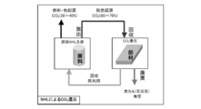
さらに、炭酸ガスを吸収させることで、天然水硬性石灰の製造時に原石から排出される脱炭起源の二酸化炭素を回収する効果が得られる。脱炭起源の二酸化炭素は天然水硬性石灰製造時の60~70%を占めており、図11に示すような二酸化炭素の循環が行われる。
天然水硬性石灰の二酸化炭素CO2回収率は、含有するCaOの化学分析による割合(表-1)を60%として、次式の通り算出できる。
CO2分子量44.0095C/CaO分子量56.0074C×NHLにおけるCaOの含有率0.60=0.47
すなわち、この炭酸化による技術を利用することで、天然水硬性石灰1(t)あたり、約470(kg)の二酸化炭素が回収できることになる。
天然水硬性石灰の二酸化炭素CO2回収率は、含有するCaOの化学分析による割合(表-1)を60%として、次式の通り算出できる。
CO2分子量44.0095C/CaO分子量56.0074C×NHLにおけるCaOの含有率0.60=0.47
すなわち、この炭酸化による技術を利用することで、天然水硬性石灰1(t)あたり、約470(kg)の二酸化炭素が回収できることになる。
製造された圧縮成型物は、水硬性石灰、消石灰、ケイ砂及び炭酸カルシウムを適切な配合比率とすることで、回収された後、焼成、消化などの製造工程を経て、原料の水硬性石灰へと再生することができる。これを原料として、圧縮成型物を製造することで、循環活用した部材の製造工程が成立する。
Claims (8)
- 7.5N/mm2以上の曲げ強さを有する、炭酸カルシウム結晶化された水硬性石灰を含む成形体。
- (a)水硬性石灰及び水を含む混合物を5N/mm2以上の圧力でプレス成形する工程、及び(b)(a)で得られたプレス成形体を炭酸ガス養生に供する工程を含む、水硬性石灰を含む成形体の製造方法。
- 15N/mm2以上の圧力でプレス成形する、請求項2に記載の製造方法。
- 炭酸ガス養生が、炭酸ガス濃度1容積%以上で2日間以上の炭酸ガス養生である、請求項2又は3に記載の製造方法。
- 骨材が水硬性石灰に対して、水硬性石灰:骨材として1:4未満の質量比で混合物中に配合される、請求項2から4の何れか一項に記載の製造方法。
- 水硬性石灰のセメント係数が0.45~0.9である、請求項2から5の何れか一項に記載の製造方法。
- 請求項2から6の何れか一項に記載の方法で製造される、水硬性石灰を含む成形体。
- 請求項1又は7に記載の成形体を加工してなる部材。
Priority Applications (5)
| Application Number | Priority Date | Filing Date | Title |
|---|---|---|---|
| CN201880023142.6A CN110461556A (zh) | 2017-03-29 | 2018-03-29 | 使用水硬性石灰的成型体及其制造方法 |
| EP18777613.3A EP3603911B1 (en) | 2017-03-29 | 2018-03-29 | Molded body using hydraulic lime and method for producing same |
| JP2019510165A JP7095896B2 (ja) | 2017-03-29 | 2018-03-29 | 水硬性石灰を用いた成形体およびその製造方法 |
| US16/498,632 US20200095166A1 (en) | 2017-03-29 | 2018-03-29 | Molded article using hydraulic lime and method for producing same |
| ES18777613T ES2959805T3 (es) | 2017-03-29 | 2018-03-29 | Cuerpo moldeado utilizando cal hidráulica y procedimiento para producirlo |
Applications Claiming Priority (2)
| Application Number | Priority Date | Filing Date | Title |
|---|---|---|---|
| JP2017065446 | 2017-03-29 | ||
| JP2017-065446 | 2017-03-29 |
Publications (1)
| Publication Number | Publication Date |
|---|---|
| WO2018181779A1 true WO2018181779A1 (ja) | 2018-10-04 |
Family
ID=63677954
Family Applications (1)
| Application Number | Title | Priority Date | Filing Date |
|---|---|---|---|
| PCT/JP2018/013373 Ceased WO2018181779A1 (ja) | 2017-03-29 | 2018-03-29 | 水硬性石灰を用いた成形体およびその製造方法 |
Country Status (6)
| Country | Link |
|---|---|
| US (1) | US20200095166A1 (ja) |
| EP (1) | EP3603911B1 (ja) |
| JP (1) | JP7095896B2 (ja) |
| CN (1) | CN110461556A (ja) |
| ES (1) | ES2959805T3 (ja) |
| WO (1) | WO2018181779A1 (ja) |
Cited By (1)
| Publication number | Priority date | Publication date | Assignee | Title |
|---|---|---|---|---|
| JP2023114666A (ja) * | 2022-02-07 | 2023-08-18 | 株式会社フジタ | コンクリート製品の製造方法 |
Families Citing this family (3)
| Publication number | Priority date | Publication date | Assignee | Title |
|---|---|---|---|---|
| CN109142054A (zh) * | 2018-08-30 | 2019-01-04 | 上海建为历保科技股份有限公司 | 一种研究传统石灰材料水硬性能的方法 |
| CN115521123A (zh) * | 2022-09-19 | 2022-12-27 | 刘泽 | 一种固化二氧化碳的方法 |
| CN118515440B (zh) * | 2024-05-20 | 2025-02-14 | 武汉市天时建筑工程有限公司 | 一种采用工业固废制备的天然水硬性石灰、制备方法及应用 |
Citations (4)
| Publication number | Priority date | Publication date | Assignee | Title |
|---|---|---|---|---|
| JPH05170497A (ja) * | 1991-10-01 | 1993-07-09 | Daiwabo Create Kk | セメント補強用ポリプロピレン繊維 |
| JPH07267713A (ja) * | 1994-03-30 | 1995-10-17 | Asahi Chem Ind Co Ltd | セメント成形体の製造方法 |
| JP2002011366A (ja) * | 2000-06-29 | 2002-01-15 | Kurita Water Ind Ltd | 灰の粉砕方法及び灰の固化成形体 |
| JP2010126420A (ja) * | 2008-11-28 | 2010-06-10 | Kusunoki Sekkai Kk | 水硬性石灰を用いた高強度建材の製造方法 |
Family Cites Families (11)
| Publication number | Priority date | Publication date | Assignee | Title |
|---|---|---|---|---|
| US3679446A (en) * | 1968-06-04 | 1972-07-25 | Osaka Packing | Molding materials of calcium silicate hydrate and shaped products thereof |
| SE410101B (sv) * | 1978-01-03 | 1979-09-24 | Malinowski Roman | Sett vid gjutning av betong |
| JPS61281056A (ja) * | 1985-06-05 | 1986-12-11 | 株式会社イナックス | セメント製品の製造方法 |
| JP4664462B2 (ja) * | 1999-10-26 | 2011-04-06 | クリオン株式会社 | 炭酸硬化体の製造方法 |
| JP2005145808A (ja) * | 2003-11-14 | 2005-06-09 | Kagawa Prefecture | 無機粉末の炭酸固化体とその製造方法 |
| CA2585348A1 (en) * | 2004-10-25 | 2006-05-04 | Nozawa Corporation | Curable composition containing as constituent material silica obtained by decomposing chrysotile and cured object |
| JP2010064902A (ja) * | 2008-09-08 | 2010-03-25 | Npo Hiroshima Junkangata Shakai Suishin Kiko | 砕石砕粉を活用する炭酸化カルシウム成形体及びその製法 |
| CN101811853B (zh) * | 2010-04-28 | 2012-09-05 | 中国文化遗产研究院 | 灌注粘结材料组合物 |
| JP2013001589A (ja) * | 2011-06-14 | 2013-01-07 | Nikko Co | 内装用建材及びその製造方法 |
| WO2013079732A1 (es) * | 2011-11-29 | 2013-06-06 | Geosilex Trenza Metal, S.L. | Procedimiento de fraguado aéreo para la obtención de piezas prefabricadas con matrices cementantes, matrices y piezas prefabricadas así obtenidas y utilización de las mismas |
| JP6238579B2 (ja) * | 2013-06-06 | 2017-11-29 | デンカ株式会社 | 炭酸化建材用の結合材およびその製造方法。 |
-
2018
- 2018-03-29 US US16/498,632 patent/US20200095166A1/en not_active Abandoned
- 2018-03-29 JP JP2019510165A patent/JP7095896B2/ja active Active
- 2018-03-29 ES ES18777613T patent/ES2959805T3/es active Active
- 2018-03-29 EP EP18777613.3A patent/EP3603911B1/en active Active
- 2018-03-29 WO PCT/JP2018/013373 patent/WO2018181779A1/ja not_active Ceased
- 2018-03-29 CN CN201880023142.6A patent/CN110461556A/zh active Pending
Patent Citations (5)
| Publication number | Priority date | Publication date | Assignee | Title |
|---|---|---|---|---|
| JPH05170497A (ja) * | 1991-10-01 | 1993-07-09 | Daiwabo Create Kk | セメント補強用ポリプロピレン繊維 |
| JPH07267713A (ja) * | 1994-03-30 | 1995-10-17 | Asahi Chem Ind Co Ltd | セメント成形体の製造方法 |
| JP2002011366A (ja) * | 2000-06-29 | 2002-01-15 | Kurita Water Ind Ltd | 灰の粉砕方法及び灰の固化成形体 |
| JP2010126420A (ja) * | 2008-11-28 | 2010-06-10 | Kusunoki Sekkai Kk | 水硬性石灰を用いた高強度建材の製造方法 |
| JP5175165B2 (ja) | 2008-11-28 | 2013-04-03 | クスノキ石灰株式会社 | 水硬性石灰を用いた高強度建材の製造方法 |
Non-Patent Citations (1)
| Title |
|---|
| See also references of EP3603911A4 |
Cited By (1)
| Publication number | Priority date | Publication date | Assignee | Title |
|---|---|---|---|---|
| JP2023114666A (ja) * | 2022-02-07 | 2023-08-18 | 株式会社フジタ | コンクリート製品の製造方法 |
Also Published As
| Publication number | Publication date |
|---|---|
| JP7095896B2 (ja) | 2022-07-05 |
| EP3603911A1 (en) | 2020-02-05 |
| EP3603911A4 (en) | 2020-12-23 |
| JPWO2018181779A1 (ja) | 2020-02-27 |
| ES2959805T3 (es) | 2024-02-28 |
| CN110461556A (zh) | 2019-11-15 |
| EP3603911B1 (en) | 2023-07-12 |
| US20200095166A1 (en) | 2020-03-26 |
Similar Documents
| Publication | Publication Date | Title |
|---|---|---|
| Zhang et al. | Engineered Cementitious Composites (ECC) with limestone calcined clay cement (LC3) | |
| Yazıcı | The effect of curing conditions on compressive strength of ultra high strength concrete with high volume mineral admixtures | |
| Liu et al. | Influence of steam curing on the compressive strength of concrete containing supplementary cementing materials | |
| US9039830B2 (en) | Cement composition containing dune sand and limestone powder, concrete products and method for making concrete products | |
| Yazıcı et al. | The effect of autoclave pressure, temperature and duration time on mechanical properties of reactive powder concrete | |
| Lanas et al. | Mechanical properties of natural hydraulic lime-based mortars | |
| US9090508B2 (en) | Geopolymer composite for ultra high performance concrete | |
| US20110271876A1 (en) | Geopolymer compositions | |
| KR101333084B1 (ko) | 고로슬래그와 csa계 시멘트를 포함하는 조강시멘트 조성물 및 이를 포함하는 콘크리트 | |
| JP7095896B2 (ja) | 水硬性石灰を用いた成形体およびその製造方法 | |
| EP2404885A2 (de) | Neue Baustoffmischungen | |
| DE202010010080U1 (de) | Neue Baustoffmischungen | |
| CN103539417A (zh) | 一种利用铁尾矿、钢渣制蒸压砖的方法 | |
| EP3129201B1 (en) | Process for the preparation of masonry composite materials | |
| Rocha et al. | The effect of recycled concrete powder (RCP) from precast concrete plant on fresh and mechanical properties of cementitious pastes | |
| JP5175165B2 (ja) | 水硬性石灰を用いた高強度建材の製造方法 | |
| Kumar et al. | Experimental study on strength properties of metakaolin and GGBS based geopolymer concrete | |
| JP7066056B2 (ja) | メカノケミカル的に改質された成分を含むエンジニアードコンクリートバインダ組成物およびその製造方法 | |
| Vivek et al. | Strength and microstructure properties of self-compacting concrete using mineral admixtures. Case study I | |
| JP4911580B2 (ja) | 低比重軽量発泡コンクリート及びその製造方法 | |
| CN115259729B (zh) | 一种过硫磷石膏-矿渣胶凝材料改性剂及其应用、过硫磷石膏-矿渣胶凝材料组合物 | |
| CN112374787A (zh) | 一种混凝土用玄武岩纤维抗裂防水剂及其制备方法 | |
| EP3914565B1 (fr) | Composition pour la formation d'un géopolymère à propriétés ignifuges et mécaniques améliorées, procédé de fabrication de ce géopolymère et ses utilisations | |
| KR20090012556A (ko) | 고강도 콘크리트 분말 혼화재 조성물 | |
| DE102009005610B3 (de) | Verfahren zur Herstellung eines hydraulischen Bindemittels |
Legal Events
| Date | Code | Title | Description |
|---|---|---|---|
| 121 | Ep: the epo has been informed by wipo that ep was designated in this application |
Ref document number: 18777613 Country of ref document: EP Kind code of ref document: A1 |
|
| ENP | Entry into the national phase |
Ref document number: 2019510165 Country of ref document: JP Kind code of ref document: A |
|
| NENP | Non-entry into the national phase |
Ref country code: DE |
|
| ENP | Entry into the national phase |
Ref document number: 2018777613 Country of ref document: EP Effective date: 20191029 |