WO2018185847A1 - ピストン - Google Patents
ピストン Download PDFInfo
- Publication number
- WO2018185847A1 WO2018185847A1 PCT/JP2017/014124 JP2017014124W WO2018185847A1 WO 2018185847 A1 WO2018185847 A1 WO 2018185847A1 JP 2017014124 W JP2017014124 W JP 2017014124W WO 2018185847 A1 WO2018185847 A1 WO 2018185847A1
- Authority
- WO
- WIPO (PCT)
- Prior art keywords
- piston
- insulating film
- heat insulating
- heat
- combustion engine
- Prior art date
- Legal status (The legal status is an assumption and is not a legal conclusion. Google has not performed a legal analysis and makes no representation as to the accuracy of the status listed.)
- Ceased
Links
Images


Classifications
-
- F—MECHANICAL ENGINEERING; LIGHTING; HEATING; WEAPONS; BLASTING
- F02—COMBUSTION ENGINES; HOT-GAS OR COMBUSTION-PRODUCT ENGINE PLANTS
- F02F—CYLINDERS, PISTONS OR CASINGS, FOR COMBUSTION ENGINES; ARRANGEMENTS OF SEALINGS IN COMBUSTION ENGINES
- F02F3/00—Pistons
- F02F3/10—Pistons having surface coverings
- F02F3/12—Pistons having surface coverings on piston heads
- F02F3/14—Pistons having surface coverings on piston heads within combustion chambers
-
- F—MECHANICAL ENGINEERING; LIGHTING; HEATING; WEAPONS; BLASTING
- F02—COMBUSTION ENGINES; HOT-GAS OR COMBUSTION-PRODUCT ENGINE PLANTS
- F02B—INTERNAL-COMBUSTION PISTON ENGINES; COMBUSTION ENGINES IN GENERAL
- F02B23/00—Other engines characterised by special shape or construction of combustion chambers to improve operation
- F02B23/08—Other engines characterised by special shape or construction of combustion chambers to improve operation with positive ignition
- F02B23/10—Other engines characterised by special shape or construction of combustion chambers to improve operation with positive ignition with separate admission of air and fuel into cylinder
-
- F—MECHANICAL ENGINEERING; LIGHTING; HEATING; WEAPONS; BLASTING
- F02—COMBUSTION ENGINES; HOT-GAS OR COMBUSTION-PRODUCT ENGINE PLANTS
- F02B—INTERNAL-COMBUSTION PISTON ENGINES; COMBUSTION ENGINES IN GENERAL
- F02B31/00—Modifying induction systems for imparting a rotation to the charge in the cylinder
- F02B31/04—Modifying induction systems for imparting a rotation to the charge in the cylinder by means within the induction channel, e.g. deflectors
- F02B31/06—Movable means, e.g. butterfly valves
-
- F—MECHANICAL ENGINEERING; LIGHTING; HEATING; WEAPONS; BLASTING
- F02—COMBUSTION ENGINES; HOT-GAS OR COMBUSTION-PRODUCT ENGINE PLANTS
- F02F—CYLINDERS, PISTONS OR CASINGS, FOR COMBUSTION ENGINES; ARRANGEMENTS OF SEALINGS IN COMBUSTION ENGINES
- F02F3/00—Pistons
- F02F3/24—Pistons having means for guiding gases in cylinders, e.g. for guiding scavenging charge in two-stroke engines
-
- F—MECHANICAL ENGINEERING; LIGHTING; HEATING; WEAPONS; BLASTING
- F16—ENGINEERING ELEMENTS AND UNITS; GENERAL MEASURES FOR PRODUCING AND MAINTAINING EFFECTIVE FUNCTIONING OF MACHINES OR INSTALLATIONS; THERMAL INSULATION IN GENERAL
- F16J—PISTONS; CYLINDERS; SEALINGS
- F16J1/00—Pistons; Trunk pistons; Plungers
- F16J1/09—Pistons; Trunk pistons; Plungers with means for guiding fluids
-
- F—MECHANICAL ENGINEERING; LIGHTING; HEATING; WEAPONS; BLASTING
- F02—COMBUSTION ENGINES; HOT-GAS OR COMBUSTION-PRODUCT ENGINE PLANTS
- F02B—INTERNAL-COMBUSTION PISTON ENGINES; COMBUSTION ENGINES IN GENERAL
- F02B23/00—Other engines characterised by special shape or construction of combustion chambers to improve operation
- F02B23/08—Other engines characterised by special shape or construction of combustion chambers to improve operation with positive ignition
- F02B23/10—Other engines characterised by special shape or construction of combustion chambers to improve operation with positive ignition with separate admission of air and fuel into cylinder
- F02B2023/106—Tumble flow, i.e. the axis of rotation of the main charge flow motion is horizontal
-
- F—MECHANICAL ENGINEERING; LIGHTING; HEATING; WEAPONS; BLASTING
- F02—COMBUSTION ENGINES; HOT-GAS OR COMBUSTION-PRODUCT ENGINE PLANTS
- F02F—CYLINDERS, PISTONS OR CASINGS, FOR COMBUSTION ENGINES; ARRANGEMENTS OF SEALINGS IN COMBUSTION ENGINES
- F02F3/00—Pistons
- F02F3/02—Pistons having means for accommodating or controlling heat expansion
- F02F3/04—Pistons having means for accommodating or controlling heat expansion having expansion-controlling inserts
- F02F3/045—Pistons having means for accommodating or controlling heat expansion having expansion-controlling inserts the inserts being located in the crown
-
- Y—GENERAL TAGGING OF NEW TECHNOLOGICAL DEVELOPMENTS; GENERAL TAGGING OF CROSS-SECTIONAL TECHNOLOGIES SPANNING OVER SEVERAL SECTIONS OF THE IPC; TECHNICAL SUBJECTS COVERED BY FORMER USPC CROSS-REFERENCE ART COLLECTIONS [XRACs] AND DIGESTS
- Y02—TECHNOLOGIES OR APPLICATIONS FOR MITIGATION OR ADAPTATION AGAINST CLIMATE CHANGE
- Y02T—CLIMATE CHANGE MITIGATION TECHNOLOGIES RELATED TO TRANSPORTATION
- Y02T10/00—Road transport of goods or passengers
- Y02T10/10—Internal combustion engine [ICE] based vehicles
- Y02T10/12—Improving ICE efficiencies
Definitions
- the present invention relates to a piston of an internal combustion engine having a heat insulating film.
- JP2014-20283A includes a heat shield film formed on the top of the piston for suppressing heat transfer to the inside of the piston, and a recess provided on the top of the piston at a distance from the outer periphery of the piston. It is disclosed that the end portion of the heat shield film is disposed in a recess provided on the top of the piston.
- the heat insulating film suppresses heat transfer, so that a decrease in the temperature in the cylinder can be suppressed and combustion efficiency can be improved.
- the heat insulating film generally has a large heat capacity per volume. Therefore, when the temperature of the heat insulating film rises due to the combustion of the air-fuel mixture, the air-fuel mixture in the cylinder receives heat by the heat insulating film heated in the intake and compression strokes, and the temperature of the air-fuel mixture rises. For this reason, there is a problem that knocking is likely to occur and knocking performance is lowered.
- An object of the present invention is to provide a piston capable of suppressing a decrease in knock performance while suppressing a decrease in cooling loss.
- a piston of an internal combustion engine wherein a concave portion that holds an intake swirl flow is formed in a crown surface of the piston, and the crown surface has a thermal conductivity that is a base material of the piston.
- FIG. 1 is an explanatory diagram of the overall configuration of the internal combustion engine system.
- FIG. 2 is an explanatory view of the tumble flow generated in the cylinder.
- FIG. 3 is an explanatory diagram of tumble flow collapse.
- FIG. 4 is a diagram showing the relationship between the fuel injection timing and the ignition timing.
- FIG. 5 is an explanatory diagram of fluid application in the vicinity of the plug.
- FIG. 6 is an explanatory diagram of an increase in turbulence caused by the fuel injection valve.
- FIG. 7 is an explanatory view showing the form of fuel spray injected from the fuel injection valve.
- FIG. 8 is an explanatory diagram of the shape of the ejection beam.
- FIG. 9 is a diagram showing the arrangement of the spark plug and the fuel injection valve.
- FIG. 10 is an explanatory diagram of the contracted flow of fuel injection.
- FIG. 11 is an explanatory diagram of a piston.
- FIG. 12 is an explanatory diagram of a heat insulating film.
- FIG. 13 is an explanatory diagram illustrating an example of a measurement result of the surface temperature of the piston.
- FIG. 1 is an explanatory diagram of the overall configuration of the internal combustion engine system 1 of the present embodiment.
- the internal combustion engine system 1 includes an internal combustion engine 10 to which an intake passage 51 and an exhaust passage 52 are connected.
- the internal combustion engine 10 is driven by the reciprocating motion of the piston 18 by burning the air-fuel mixture sucked from the intake passage 51.
- the exhaust gas after combustion is discharged into the exhaust passage 52.
- a tumble control valve 16 is provided in the intake passage 51.
- the tumble control valve 16 generates a tumble flow in the cylinder by closing part of the cross section of the intake passage 51.
- a collector tank 46 is provided in the intake passage 51.
- An EGR passage 53 b is connected to the collector tank 46.
- an air flow meter 33 is provided upstream of the collector tank 46.
- the controller 50 connected to the air flow meter 33 acquires the flow rate (intake amount) of air flowing through the intake passage 51 from the air flow meter 33.
- An intake air temperature sensor 34 is provided in the vicinity of the air flow meter 33 in the intake passage 51.
- the controller 50 connected to the intake air temperature sensor 34 acquires the temperature of the air passing through the intake passage 51 (intake air temperature) from the intake air temperature sensor 34.
- an electronic control throttle 41 is provided in the intake passage 51, and the throttle opening is controlled by the controller 50.
- the exhaust passage 52 is provided with exhaust catalysts 44 and 45 for exhaust purification.
- a three-way catalyst or the like is used for the exhaust catalysts 44 and 45.
- the exhaust catalyst 44 and the exhaust catalyst 45 branch to an EGR passage 53 a connected to the collector tank 46.
- the EGR cooler 43 is provided in the EGR passage 53a.
- An EGR valve 42 is provided in the EGR passage 53b.
- the EGR valve 42 is connected to the controller 50. The opening degree of the EGR valve 42 is controlled by the controller 50 in accordance with the operating conditions of the internal combustion engine 10.
- the internal combustion engine 10 includes an ignition plug 11, a fuel injection valve 12, an intake side variable valve mechanism 13, and an exhaust side variable valve mechanism 14. Further, the internal combustion engine 10 includes a fuel injection pump 15 and a piston 18.
- the fuel injection valve 12 is a direct injection valve that directly injects fuel into the cylinder, and is provided in the vicinity of the spark plug 11.
- the spark plug 11 performs spark ignition in the combustion chamber of the internal combustion engine 10.
- the spark plug 11 is connected to the controller 50, and the spark ignition timing is controlled by the controller 50.
- the fuel injection valve 12 is connected to the controller 50 and the fuel injection timing is controlled. In the present embodiment, so-called multistage injection is performed in which fuel injection is performed a plurality of times including the intake stroke.
- the fuel injection pump 15 supplies pressurized fuel to the fuel injection valve 12.
- the intake side variable valve mechanism 13 changes the opening / closing timing of the intake valve.
- the exhaust side variable valve mechanism 14 changes the opening / closing timing of the exhaust valve.
- the intake side variable valve mechanism 13 and the exhaust side variable valve mechanism 14 are connected to a controller 50.
- the controller 50 controls the opening / closing timing of the intake side variable valve mechanism 13 and the exhaust side variable valve mechanism 14.
- the intake side variable valve mechanism 13 and the exhaust side variable valve mechanism 14 are shown, you may have any one.
- the internal combustion engine 10 is provided with a knock sensor 21, a fuel pressure sensor 24, a crank angle sensor 26, and an in-cylinder pressure sensor 35.
- the knock sensor 21 and the fuel pressure sensor 24 detect the knock state of the internal combustion engine 10 and the fuel pressure of the fuel sent from the fuel injection pump 15, and send them to the controller 50.
- crank angle sensor 26 detects the crank angle in the internal combustion engine 10.
- the crank angle sensor 26 is connected to the controller 50 and sends the crank angle of the internal combustion engine 10 to the controller 50.
- the in-cylinder pressure sensor 35 detects the pressure in the combustion chamber in the internal combustion engine 10.
- the in-cylinder pressure sensor 35 is connected to the controller 50 and sends the pressure in the combustion chamber of the internal combustion engine 10 to the controller 50.
- the controller 50 reads the outputs from the above-mentioned various sensors and other sensors not shown, and controls the fuel injection timing, ignition timing, valve opening / closing timing, air-fuel ratio, etc. based on these outputs and a previously stored map or the like. To do.
- FIG. 2 is an explanatory view of the tumble flow generated in the cylinder of the internal combustion engine 10 of the present embodiment.
- FIG. 3 is an explanatory diagram of the tumble flow collapse of the internal combustion engine 10 of the present embodiment.
- FIGS. 2 and 3 show an intake passage 51, an exhaust passage 52, a spark plug 11, a fuel injection valve 12, and a tumble control valve 16. 2 and 3, the center electrode 11a and the outer electrode 11b of the spark plug 11 are shown.
- FIG. 2 the tumble flow in the cylinder during the intake stroke is indicated by an arrow.
- FIG. 3 the tumble flow in the cylinder during the compression stroke is indicated by arrows.
- the piston 18 of the present embodiment has a shallow plate 61 as a recess formed on the crown surface.
- the shallow plate 61 is formed in a smooth concave shape suitable for maintaining a tumble flow.
- the piston 18 ascends during the compression stroke, so that the combustion chamber in the cylinder is narrowed.
- the tumble flow is crushed and gradually cannot be maintained, and eventually collapses.
- the controller 50 controls to perform fuel injection further after the tumble flow collapse until the plug discharge channel generation.
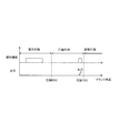
- FIG. 4 is an explanatory diagram showing the relationship between the fuel injection timing and the ignition timing in the present embodiment.
- the fuel may be injected after the expansion stroke injection in consideration of the possibility that part of the spray adheres to the center electrode 11a and the outer electrode 11b of the spark plug 11 due to the turbulence of the air flow caused by the fuel spray.
- FIG. 5 is an explanatory diagram of flow application in the vicinity of the plug.
- the fuel injection valve 12 is a direct injection valve and is provided in the vicinity of the spark plug 11. Therefore, a part of the injected fuel passes near the discharge gap. Therefore, the fuel can be injected in the vicinity of the spark plug by performing the fuel injection after the tumble flow has collapsed.
- FIG. 6 is an explanatory diagram of an increase in turbulent flow in the cylinder by the fuel injection valve 12 of the present embodiment.
- the horizontal axis indicates the crank angle
- the vertical axis indicates the turbulence intensity.
- the tumble flow collapses during the compression stroke. For this reason, the turbulence intensity gradually decreases in the compression stroke. Therefore, as shown in FIG. 6, the turbulence intensity can be increased by performing fuel injection in accordance with the ignition timing of the spark plug 11. That is, a flow can be given by performing fuel injection.
- FIG. 7 is an explanatory view showing the form of fuel spray injected from the fuel injection valve 12 of the present embodiment.
- FIG. 8 is an explanatory diagram of the plane including the circle A in FIG. 7 observed from the direction of arrow VIII in FIG.
- each spray beam has a conical shape in which the spray cross section becomes wider as the distance from the nozzle holes increases.
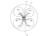
- FIG. 9 is an explanatory diagram showing the positional relationship between the spray beam B1-B6 and the spark plug 11 of the present embodiment.
- the fuel injection valve 12 is disposed on a one-dot chain line C that is a bisector of an angle formed by the central axis B2c of the spray beam B2 and the central axis B3c of the spray beam B3.
- FIG. 10 is an explanatory view for explaining the effect of the fuel injection of the present embodiment.
- the fuel injected from the fuel injection valve 12 is divided into droplets and sprayed, and moves forward while taking in the surrounding air as indicated by the thick arrows in the figure. As a result, air turbulence occurs around the spray.
- the fluid when there is an object (including a fluid) around the fluid, the fluid is attracted to the object by the so-called Coanda effect and flows along the object. That is, in the arrangement shown in FIG. 9, a so-called contracted flow occurs in which the spray beam B ⁇ b> 2 and the spray beam B ⁇ b> 3 are attracted as shown by thin line arrows in FIG. 10. Thereby, a strong turbulent flow is generated between the spray beam B2 and the spray beam B3, and the plug discharge channel can be extended by the turbulent flow.
- FIG. 11 is an explanatory view of the piston 18 of the present embodiment, and shows a front view of the piston 18 and a side view of the piston 18.
- a shallow plate 61 is formed on the crown surface of the piston 18 as a recess suitable for maintaining a tumble flow.
- the shallow dish 61 is provided with a heat insulating film 60 as described later.
- the piston 18 is made of a metal base material such as an aluminum alloy.
- the heat insulating film 60 of the present embodiment is not provided on the crown surface of the piston 18, the temperature of the crown surface of the piston 18 is hardly increased even in the combustion of the air-fuel mixture because the base material of the piston 18 has a high thermal conductivity. As a result, the cooling efficiency is reduced by the cooling loss.
- a heat insulating film has been formed on the crown surface of the piston 18 for the purpose of preventing a decrease in the temperature of the crown surface of the piston 18 and suppressing cooling loss.
- a heat insulating film is generally formed by forming a porous alumite film on the surface of the piston 18 by anodizing treatment or coating a metal, ceramics or the like having low thermal conductivity. there were.
- the heat insulating film thus formed had a low thermal conductivity and a large heat capacity per volume.
- the heat capacity per volume is large, in an operation state in which the temperature of the crown surface of the piston 18 increases greatly, such as in a high load operation, the temperature of the increased heat insulating film remains high, and the temperature of the crown surface of the piston 18 remains high. It is hard to decline. If the temperature of the crown surface of the piston 18 is kept high, the air-fuel mixture is heated by heat exchange between the air-fuel mixture and the heat insulating film in the intake stroke and the compression stroke.
- the heat insulating film 60 formed on the shallow plate 61 (recessed portion) on the crown surface of the piston 18 is made of a material having a lower thermal conductivity than the base material of the piston 18 and a smaller heat capacity per volume. Configured. Since the heat insulating film 60 made of such a material has a small heat capacity, even if the temperature of the heat insulating film 60 rises during combustion, the temperature of the heat insulating film 60 is not maintained as the in-cylinder temperature decreases thereafter. descend. Such a characteristic that the temperature of the heat insulating film follows the temperature in the cylinder is called a “swing characteristic”.
- the heat insulating film 60 of the present embodiment is formed by applying a porous resin material.
- the resin material is preferably a material having heat resistance, low thermal conductivity, and swing characteristics.
- a porous polyimide resin is used.
- a heat insulating film forming portion 63 in which a heat insulating film 60 made of a porous resin material is formed in a region where the shallow dish 61 is formed on the crown surface of the piston 18 is provided.
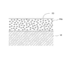
- FIG. 12 is an explanatory diagram of the heat insulating film 60 of the present embodiment.
- the heat insulating film 60 is formed by covering a shallow plate 61 on the crown surface of the piston 18 with a resin material.
- the resin material has a number of holes 60a as shown in FIG. Since the heat insulation film 60 has a large number of holes 60a distributed, the heat insulation film 60 having a low thermal conductivity and a small heat capacity per volume and having a swing characteristic can be formed.
- the holes 60a may be arranged so as to be uniformly distributed in the heat insulating film 60, or may be arranged so that the density of the holes 60a increases or decreases according to the thickness direction of the heat insulating film 60. Good.
- the heat insulating film 60 may be any material as long as it is a porous material having a swing characteristic in thermal characteristics. For example, it may be formed by spraying a ceramic material such as zirconia on the crown surface of the piston 18 or may be formed by spraying and plating a metal material such as nickel or molybdenum on the crown surface of the piston 18. Further, a porous film may be formed by performing a treatment such as anodizing on the crown surface of the piston 18.
- a heat insulating film 60 is provided in a portion other than the shallow plate 61, that is, in the vicinity of the inner diameter of the cylinder bore positioned outside the inner peripheral region of the piston including the shallow plate 61 (outer region).
- a heat insulating film non-forming part 62 that is not formed is provided. In the heat insulation film non-forming part 62, the base material of the piston 18 is exposed in the cylinder.
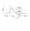
- FIG. 13 is an explanatory diagram showing an example of the measurement result of the surface temperature of the piston 18 having the heat insulating film 60 of the present embodiment.
- the horizontal axis indicates the crank angle
- the vertical axis indicates the surface temperature of the piston 18.
- the transition of the heat insulating film surface temperature of the piston 18 having the heat insulating film 60 of the present embodiment is shown by a thick solid line
- the surface temperature of the piston 18 not having the heat insulating film 60 is shown by a one-dot chain line, and has no swing characteristics.
- the heat insulating film surface temperature of the piston 18 having the conventional heat insulating film is indicated by a dotted line.
- the surface temperature of the piston 18 that does not have the heat insulating film 60 has a higher thermal conductivity than the piston 18 that has the heat insulating film 60. For this reason, as shown by the dotted line in FIG. 5, the surface temperature rises slightly during combustion of the air-fuel mixture performed immediately after the top dead center of the piston 18, and thereafter the surface temperature is relatively low due to heat conduction. Transition to.
- the surface temperature of the heat insulating film of the piston 18 having a conventional heat insulating film having no swing characteristic that is, a heat insulating film having low thermal conductivity and a small heat capacity per volume
- a heat insulating film having low thermal conductivity and a small heat capacity per volume is shown by a one-dot chain line in FIG. become. That is, since the thermal conductivity of the conventional heat insulating film is small, the surface temperature rises due to the combustion of the air-fuel mixture performed immediately after the top dead center of the piston 18, and the surface temperature remains elevated during the exhaust stroke and the intake stroke. .
- the surface temperature of the heat insulating film 60 having the swing characteristics according to the present embodiment temporarily rises due to the combustion of the air-fuel mixture performed immediately after the top dead center of the piston 18 as shown by the thick solid line in FIG. To do. Thereafter, since the heat capacity per volume of the heat insulating film 60 is small, heat is transferred to the piston 18 and the surface temperature gradually decreases. Thereafter, in the intake stroke, the surface temperature of the piston 18 (not indicated by the dotted line) that does not have a heat insulating film, that is, a temperature equivalent to the base material of the piston 18 is lowered.
- the surface temperature of the heat insulating film 60 having the swing characteristic according to the present embodiment temporarily rises with combustion in the compression stroke, but thereafter falls due to heat conduction of the piston 18. Therefore, even if the air-fuel mixture flows on the surface of the shallow dish 61 due to the tumble flow, heat transfer to the air-fuel mixture can be suppressed, and the knock performance can be prevented from being lowered.
- the shallow plate 61 serving as the concave portion that holds the intake swirl flow is formed on the crown surface of the internal combustion engine 10, and the crown surface of the piston 18 has a thermal conductivity. Is lower than the base material of the piston 18 and the heat capacity per volume is smaller than that of the base material of the piston 18, and a heat insulating film forming portion 63 including the heat insulating film 60 and the cylinder bore side of the internal combustion engine 10 relative to the heat insulating film forming portion 63. And a heat insulation film non-formation part 62 that does not include the heat insulation film 60.
- the temperature of the crown surface of the piston 18 rises during the combustion of the air-fuel mixture in the expansion stroke.
- the temperature of the heat insulation film 60 can be lowered in the intake stroke and the compression stroke.
- the temperature of the crown surface can be lowered by the heat transfer of the base material of the piston 18 without the heat insulating film 60.
- the heat insulating film forming portion 63 in which the heat insulating film 60 is formed on the crown surface of the piston 18 is configured to coincide with the region where the shallow dish 61 as the concave portion is formed.
- the shallow plate 61 of the piston 18 is configured to hold the tumble flow as the intake air swirling flow of the intake air flowing into the cylinder of the internal combustion engine 10.
- heat exchange with the air-fuel mixture flowing in the shallow dish 61 by tumble flow can be suppressed by the heat insulating film 60, so that the cooling loss during combustion is suppressed and the intake stroke and the compression stroke are suppressed. Knock performance can be improved.
- the heat insulating film 60 is formed of a porous resin material such as porous polyimide applied to the crown surface of the piston 18.
- the heat insulating film can be formed by a simple process of applying a resin material, so that the cost of the manufacturing process of the piston 18 can be reduced as compared with the thermal spraying of an anodized film or ceramics. be able to.
- the shallow plate 61 of the piston 18 has a shape that holds the tumble flow as the intake swirl flow, but is not limited thereto.
- the shallow plate 61 may have a shape that maintains the swirl flow.
- the shallow plate 61 does not necessarily have a concave shape, and may have any shape as long as the shape holds the intake swirl flow (tumble flow, swirl flow).
- a valve recess may be formed on the crown surface of the piston 18.
- the heat insulating film forming portion 63 where the heat insulating film 60 is formed does not necessarily coincide with the region of the shallow dish 61.
- the heat insulating film 60 may be formed outside the outer periphery of the shallow dish 61, or the heat insulating film 60 may be formed inside the outer periphery of the shallow dish 61.
Landscapes
- Engineering & Computer Science (AREA)
- General Engineering & Computer Science (AREA)
- Chemical & Material Sciences (AREA)
- Combustion & Propulsion (AREA)
- Mechanical Engineering (AREA)
- Combustion Methods Of Internal-Combustion Engines (AREA)
- Pistons, Piston Rings, And Cylinders (AREA)
Abstract
内燃機関のピストンであって、ピストンの冠面には、吸気旋回流を保持する凹部が形成されており、冠面は、熱伝導率が前記ピストンの母材よりも低く、かつ、体積当たりの熱容量が前記ピストンの母材よりも小さい断熱膜を有する断熱膜形成部と、断熱膜形成部よりも内燃機関のシリンダボア側の外側位置にあって断熱膜を有しない断熱膜非形成部と、を備える。
Description
本発明は、内燃機関のピストンであって、断熱膜を有するピストンに関する。
JP2014-20283Aには、ピストンの頂部に形成され、ピストンの内部への熱伝達を抑制するための遮熱膜と、ピストンの頂部にピストンの外周部から間隔を隔てて設けられる凹部とを備え、遮熱膜の末端部分が、ピストンの頂部に設けた凹部に配設されることが開示されている。
このような従来技術によれば、断熱膜(遮熱膜)が熱伝達を抑制することにより、気筒内の温度の低下を抑制できて、燃焼効率が向上できるという利点がある。
一方、断熱膜は体積当たりの熱容量が一般的に大きい。そのため、混合気の燃焼により断熱膜の温度が上昇することで、吸気、圧縮行程において熱せられた断熱膜により気筒内の混合気が受熱し、混合気の温度が上昇する。このために、ノッキングが発生しやすくなり、ノック性能が低下するという問題がある。
本発明の目的は、冷却損失の低減を抑制しながら、ノック性能の低下を抑制できるピストンを提供することである。
本発明のある態様によれば、内燃機関のピストンであって、ピストンの冠面には、吸気旋回流を保持する凹部が形成されており、冠面は、熱伝導率が前記ピストンの母材よりも低く、かつ、体積当たりの熱容量が前記ピストンの母材よりも小さい断熱膜を有する断熱膜形成部と、断熱膜形成部よりも内燃機関のシリンダボア側の外側位置にあって断熱膜を有しない断熱膜非形成部と、を備える。
以下、図面等を参照して、本発明の実施形態について説明する。
図1は、本実施形態の内燃機関システム1の全体構成の説明図である。内燃機関システム1は、吸気通路51及び排気通路52がそれぞれ接続される内燃機関10を備える。内燃機関10は、吸気通路51から吸気された混合気が燃焼されることでピストン18が往復運動を行ない駆動する。燃焼後の排ガスは排気通路52へと排出される。
吸気通路51にはタンブルコントロールバルブ16が設けられる。タンブルコントロールバルブ16は、吸気通路51の流路断面の一部を閉塞することにより筒内にタンブル流動を生成する。
吸気通路51にはコレクタタンク46が設けられる。コレクタタンク46にはEGR通路53bが接続される。
吸気通路51において、コレクタタンク46の上流にはエアフローメータ33が設けられる。エアフローメータ33に接続するコントローラ50は、エアフローメータ33から吸気通路51内を流れる空気の流量(吸気量)を取得する。また、吸気通路51のエアフローメータ33の近傍には吸気温センサ34が設けられる。吸気温センサ34に接続するコントローラ50は、吸気温センサ34から吸気通路51を通過する空気の温度(吸気温)を取得する。
また、吸気通路51には電子制御スロットル41が設けられ、コントローラ50によりスロットル開度が制御される。
排気通路52には排気浄化用の排気触媒44、45が設けられる。排気触媒44、45には三元触媒等が用いられる。排気通路52において、排気触媒44と排気触媒45との間で、コレクタタンク46と接続するEGR通路53aに分岐する。
EGR通路53aにはEGRクーラー43が設けられる。また、EGR通路53bには、EGRバルブ42が設けられる。EGRバルブ42は、コントローラ50に接続される。内燃機関10の運転条件に応じて、コントローラ50によりEGRバルブ42の開度が制御される。
内燃機関10は、点火プラグ11と燃料噴射弁12と吸気側可変動弁機構13と排気側可変動弁機構14とを備える。さらに、内燃機関10は、燃料噴射ポンプ15とピストン18とを備える。燃料噴射弁12は、筒内に燃料を直接噴射する直上噴射弁であり、点火プラグ11の近傍に設けられる。
点火プラグ11は、内燃機関10の燃焼室内で火花点火を行う。点火プラグ11は、コントローラ50に接続され、コントローラ50によって火花点火時期が制御される。
燃料噴射弁12は、コントローラ50に接続され、燃料噴射時期が制御される。本実施形態では、吸気行程を含めて複数回燃料噴射を行う、いわゆる多段噴射が行われる。燃料噴射ポンプ15は、加圧した燃料を燃料噴射弁12に供給する。
吸気側可変動弁機構13は、吸気弁の開閉時期を変化させる。排気側可変動弁機構14は、排気弁の開閉時期を変化させる。吸気側可変動弁機構13及び排気側可変動弁機構14は、コントローラ50に接続される。コントローラ50は、吸気側可変動弁機構13及び排気側可変動弁機構14の開閉時期を制御する。本実施形態では、吸気側可変動弁機構13及び排気側可変動弁機構14を示しているが、いずれか一方を有するものであってもよい。
内燃機関10には、ノックセンサ21、燃圧センサ24、クランク角センサ26及び筒内圧センサ35が設けられる。ノックセンサ21及び燃圧センサ24は、内燃機関10のノックの状態及び燃料噴射ポンプ15から送られる燃料の燃圧を検出し、コントローラ50に送る。
同様に、クランク角センサ26は、内燃機関10におけるクランク角を検出する。クランク角センサ26はコントローラ50に接続され、内燃機関10のクランク角をコントローラ50に送る。筒内圧センサ35は、内燃機関10における燃焼室の圧力を検出する。筒内圧センサ35はコントローラ50に接続され、内燃機関10の燃焼室の圧力をコントローラ50に送る。
コントローラ50は、前述の各種センサ及び図示しないその他のセンサからの出力を読み込み、これらの出力及び予め記憶されたマップ等に基づいて、燃料噴射時期、点火時期、バルブ開閉時期、空燃比等を制御する。
図2は、本実施形態の内燃機関10の筒内に生ずるタンブル流動の説明図である。図3は、本実施形態の内燃機関10のタンブル流動崩壊の説明図である。
図2及び図3には、吸気通路51、排気通路52、点火プラグ11、燃料噴射弁12及びタンブルコントロールバルブ16が示されている。また、図2及び図3には、点火プラグ11の中心電極11aと外側電極11bが示されている。
図2では、吸気行程における筒内のタンブル流動が矢印で示されている。図3では、圧縮行程における筒内のタンブル流動が矢印で示されている。
本実施形態のピストン18は、その冠面に凹部としての浅皿61が形成されている。浅皿61は、タンブル流動を保持するのに適した、なめらかな凹形状に形成されている。
内燃機関10の吸気行程において、タンブルコントロールバルブ16が閉じられていると、吸気は吸気通路51の図中上側に偏って流れ、筒内に流入する。その結果、図示するように筒内には縦方向に旋回する吸気旋回流動(タンブル流動)が形成される。タンブル流動は、ピストン18の冠面の浅皿61の表面に沿って流動することで、タンブル流動が保持される。なお、ピストン18の冠面のシリンダボア近傍付近(図2中Aで示す箇所)では、タンブル流動から外れ、混合気の流動が弱くなる。
その後、図3に示すように、圧縮行程においてピストン18が上昇することにより筒内の燃焼室が狭まる。燃焼室が狭くなると、タンブル流動は押しつぶされ、徐々にその流動を維持できなくなり、やがて崩壊する。
タンブル流動が維持されている間に燃料と吸気との混合が促進される。よって、タンブル流動が崩壊するときには、筒内の混合気は均質化している。しかし、タンブル流動の崩壊後は、筒内の混合気の流動が弱まる。筒内の混合気の流動が弱まると、点火プラグ11の点火時にプラグ放電チャンネルが十分伸長しない状態となる。なお、「プラグ放電チャンネル」とは、点火プラグ11の中心電極11a、外側電極11bの間に生ずるアークである。特に、点火プラグ11の近傍の混合気の流動が弱まると、火花点火により発生した火炎核が成長し難くなるので、失火やパーシャルバーンを起こしやすくなる。
そこで、圧縮上死点以降のプラグ点火時にプラグ放電チャンネルが十分伸長するように、点火時近傍のタイミングにおいて点火プラグ近傍に流動を与える。具体的には、コントローラ50が、前述した多段噴射の吸気行程と膨張行程に加えて、タンブル流動崩壊後からプラグ放電チャンネル生成までの間に、さらに燃料噴射を行なうように制御する。
図4は、本実施形態における燃料噴射時期と点火時期との関係を示す説明図である。
図4に示すように、吸気行程において燃料噴射を行なうだけでなく、圧縮行程においても点火プラグ11の点火時期に合わせてさらに燃料噴射を行なう。燃料噴射弁12は点火プラグ11の近傍に配置されているので、噴射された燃料の一部は点火プラグ11の近傍を通過する。これにより、点火プラグ11近傍に流動が付与される。
なお、燃料噴霧による気流の乱れによって噴霧の一部が点火プラグ11の中心電極11a、外側電極11bに付着する可能性を考慮して、膨張行程噴射の後に燃料を噴射してもよい。
図5は、プラグ近傍における流動付与の説明図である。上記したように、燃料噴射弁12は直上噴射弁であり、点火プラグ11の近傍に設けられる。そのため、噴射された燃料の一部は放電ギャップ近傍を通過することになる。よって、タンブル流動が崩壊した後に燃料噴射が行われることにより、点火プラグ近傍に流動を付与することができる。
図6は、本実施形態の燃料噴射弁12による筒内の乱流増加の説明図である。図6において、横軸はクランク角を示し、縦軸は乱流強度を示す。
前述のように圧縮行程でタンブル流動は崩壊する。そのため、圧縮行程で乱流強度も徐々に弱くなる。そこで、図6に示すように、点火プラグ11の点火時期に合わせて燃料噴射を行うことによって、乱流強度を高めることができる。すなわち、燃料噴射を行うことによって流動を与えることができる。
図7は、本実施形態の燃料噴射弁12から噴射される燃料噴霧の形態を示す説明図である。図8は、図7の円Aを含む平面を図7の矢印VIII方向から観察した説明図である。
本実施形態の燃料噴射弁12は、6つの噴孔から燃料が噴射される。6つの噴孔から噴射される燃料噴霧(以下、噴霧ビームともいう)をB1-B6としたとき、各噴霧ビームは噴孔から遠ざかるほど噴霧断面が広くなる円錐形状である。
図9は、本実施形態の噴霧ビームB1-B6と点火プラグ11との位置関係を示す説明図である。燃料噴射弁12は、噴霧ビームB2の中心軸B2cと噴霧ビームB3の中心軸B3cとがなす角の二等分線である一点鎖線C上に配置される。
図10は、本実施形態の燃料噴射による効果を説明する説明図である。燃料噴射弁12から噴射された燃料は、液滴へと分裂して噴霧になり、図中の太線矢印のように周囲の空気を取り込みながら前進する。これにより噴霧の周りに気流の乱れが発生する。
また、流体は、周囲に物体(流体を含む)がある場合には、いわゆるコアンダ効果によってその物体に引き寄せられ、その物体に沿って流れる。すなわち、図9に示す配置では、噴霧ビームB2と噴霧ビームB3とが図10の細線矢印のように引き合う、いわゆる縮流が生じる。これにより、噴霧ビームB2と噴霧ビームB3との間には、強い乱流れが生じ、乱流によってプラグ放電チャンネルを伸長させることができる。
次に、本実施形態のピストン18の構成を説明する。
図11は、本実施形態のピストン18の説明図であり、ピストン18の正面図及びピストン18の側面図を示す。
ピストン18の冠面には、タンブル流動を保持するのに適した凹部としての浅皿61が形成されている。この浅皿61には、後述するように断熱膜60が備えられる。
ピストン18は、アルミ合金等の金属の母材により構成される。ピストン18の冠面に本実施形態の断熱膜60を備えない場合、ピストン18の母材の熱伝導率が大きいため、混合気の燃焼においてもピストン18の冠面の温度は上昇しにくい一方で、このことによる冷却損失により燃焼効率が低下する。
そこで、従来、ピストン18の冠面の温度の低下を防ぎ、冷却損失を抑制することを目的として、ピストン18の冠面に断熱膜を形成することが行なわれてきた。ピストン18の冠面に断熱膜を形成することにより、ピストン18の冠面の温度が低下し難くなり、冷却損失が抑制され燃焼効率の低下が防止できる。従来の断熱膜は、ピストン18の表面に陽極酸化処理により多孔質のアルマイト被膜を形成したり、熱伝導性の低い金属やセラミックス等を被覆したりすることにより、形成されることが一般的であった。
このように形成される断熱膜は、熱伝導率が低く、かつ、体積当たりの熱容量が大きいものであった。体積当たりの熱容量が大きい場合は、高負荷運転など、ピストン18の冠面の温度が大きく上昇するような運転状態では、上昇した断熱膜の温度が高いままとなり、ピストン18の冠面の温度が低下しにくい。ピストン18の冠面の温度が高いまま維持されると、吸気行程及び圧縮行程において混合気と断熱膜との間で熱交換が行なわれることで混合気が加熱される。
特に、ピストン18の浅皿61によりタンブル流動が維持されることで、混合気と断熱膜とが触れる度合いが大きくなり、断熱膜から混合気への熱伝達量が大きくなる。このために混合気の温度が上昇しやすくなり、異常点火が発生するなど、ノック性能が低下するという問題があった。
そこで、本実施形態では、ピストン18冠面の浅皿61(凹部)に形成される断熱膜60を、ピストン18の母材よりも熱伝導率が低く、かつ、体積当たりの熱容量が小さい材質により構成した。このような材質からなる断熱膜60は、熱容量が小さいことにより、燃焼時に断熱膜60の温度が上昇しても、その後筒内温度の低下に伴って断熱膜60の温度が維持されることなく低下する。このように、筒内の温度に伴って断熱膜の温度が追従するような特性を、「スイング特性」と呼ぶ。
本実施形態の断熱膜60は、多孔質の樹脂材料を塗布することにより形成される。樹脂材料は、耐熱性を有し、熱伝導率が低く、かつ、スイング特性を有する材料が好適であり、例えば多孔質ポリイミド樹脂が用いられる。
本実施形態では、図11に示すように、ピストン18の冠面において、浅皿61が形成される領域に、多孔質の樹脂材料からなる断熱膜60が形成された断熱膜形成部63を備える。
図12は、本実施形態の断熱膜60の説明図である。
断熱膜60は、ピストン18の冠面の浅皿61に樹脂材料を被覆することで形成される。樹脂材料は図12に示すように多数の空孔60aを有する。断熱膜60は、多数の空孔60aが分布していることより、熱伝導率が低く、かつ、体積当たりの熱容量が小さい、スイング特性を有する断熱膜60を形成することができる。空孔60aは、断熱膜60において一様に分布するように配置されていてもよいし、断熱膜60の厚さ方向にしたがって空孔60aの密度が増加又は減少するように配置されていてもよい。
なお、断熱膜60は、熱特性においてスイング特性を有する多孔質材料であればどのような材質でもよい。例えば、ジルコニア等のセラミックス材料をピストン18の冠面に溶射することで形成してもよいし、ニッケル、モリブデン等の金属材料をピストン18冠面に溶射、鍍金することで形成してもよい。また、ピストン18の冠面に陽極酸化処理等の処理を行なうことにより多孔質膜を形成してもよい。
また、ピストン18の冠面において、浅皿61以外の部分、すなわち、浅皿61を含むピストンの内周側領域よりも外側に位置するシリンダボア内径近傍付近(外側領域)には、断熱膜60が形成されていない断熱膜非形成部62を備える。断熱膜非形成部62においては、ピストン18の母材が筒内に露出している。
このように構成することで、断熱膜非形成部62では、燃焼後、熱伝導により速やかにピストン18冠面の温度が低下するため、タンブル流動から外れて混合気の流動が遅くなるシリンダボア近傍付近(図2中Aで示す箇所)において、混合気を過熱することがない。これにより、未燃焼の混合気の異常燃焼を防止することができるので、ノッキングの発生を防止できる。
図13は、本実施形態の断熱膜60を有するピストン18の表面温度の計測結果の一例を示す説明図である。図13において、横軸はクランク角度を示し、縦軸はピストン18の表面温度を示す。
図13では、本実施形態の断熱膜60を有するピストン18の断熱膜表面温度の推移を太実線で示し、断熱膜60を有しないピストン18の表面温度を一点鎖線で示し、スイング特性を有しない従来の断熱膜を有するピストン18の断熱膜表面温度を点線で示す。
断熱膜60を有しないピストン18の表面温度は、断熱膜60を有するピストン18と比較して熱伝導率が大きい。このため、図5中点線で示すように、ピストン18の上死点直後に行なわれる混合気の燃焼時において表面温度の上昇は僅かであり、その後は熱伝導により表面温度は比較的低い状態で推移する。
一方で、スイング特性を有しない従来の断熱膜、すなわち、熱伝導率が低く、かつ、体積当たりの熱容量が小さい断熱膜を有するピストン18の断熱膜表面温度は、図5中一点鎖線で示すようになる。すなわち、従来の断熱膜では熱伝導率が小さいため、ピストン18の上死点直後に行なわれる混合気の燃焼により表面温度が上昇し、排気行程及び吸気行程においても表面温度が上昇したままとなる。
これらに対して、本実施形態のスイング特性を有する断熱膜60の表面温度は、図5中太実線で示すように、ピストン18上死点直後に行なわれる混合気の燃焼により表面温度が一旦上昇する。その後は、断熱膜60の体積当たりの熱容量が小さいことから、熱がピストン18に伝達されて表面温度は徐々に低下する。その後、吸気行程においては、断熱膜を有さないピストン18の表面温度(点線で示す)、すなわちピストン18の母材と同等の温度まで低下する。
このように、本実施形態のスイング特性を有する断熱膜60の表面温度は、圧縮行程における燃焼に伴って一時的に上昇するが、その後はピストン18の熱伝導によって低下する。従って、タンブル流動により浅皿61の表面に混合気が流動しても、混合気への熱伝達を抑制できて、ノック性能の低下を防止できる。
次に、本実施形態の効果を説明する。
上記の通り本実施形態では、内燃機関10のピストン18であって、ピストン18の冠面に吸気旋回流を保持する凹部としての浅皿61が形成され、ピストン18の冠面は、熱伝導率がピストン18の母材よりも低く、かつ、体積当たりの熱容量がピストン18の母材よりも小さい断熱膜60を備える断熱膜形成部63と、断熱膜形成部63よりも内燃機関10のシリンダボア側の外側位置に形成され、断熱膜60を備えない断熱膜非形成部62と、を備える。
このように構成された本実施形態では、膨張行程において混合気の燃焼時にピストン18の冠面の温度は上昇する。一方で、吸気行程、圧縮行程において、断熱膜60の温度を低くできる。また、シリンダボア近傍付近(図2中Aで示す箇所、断熱膜非形成部62)では、断熱膜60を有さずピストン18の母材の熱伝達により冠面の温度を低くできる。これにより、燃焼時での冷却損失を抑制しつつ、吸気行程、圧縮行程時でのノック性能を向上できる。
また、本実施形態では、ピストン18の冠面において断熱膜60が形成された断熱膜形成部63は、凹部としての浅皿61が形成される領域と一致するように構成した。このように構成することにより、吸気行程、圧縮行程において、吸気旋回流による混合気の流動が大きくなる浅皿61での熱交換を抑制できるので、燃焼時での冷却損失を抑制しつつ、吸気行程、圧縮行程時でのノック性能を向上できる。
また、本実施形態では、ピストン18の浅皿61は、内燃機関10の筒内に流入する吸気の吸気旋回流としてタンブル流動を保持するように構成した。このように構成することにより、タンブル流動により浅皿61で流動する混合気との熱交換を断熱膜60により抑制できるので、燃焼時の冷却損失を抑制しつつ、吸気行程、圧縮行程時でのノック性能を向上できる。
また、本実施形態では、断熱膜60は、ピストン18の冠面に塗布された多孔質ポリイミド等の多孔質樹脂材料により形成される。このように構成することにより、樹脂材料を塗布するという簡易な工程により断熱膜を形成することができるので、陽極酸化皮膜やセラミックスの溶射等に比べると、ピストン18の製造工程のコストを低減することができる。
以上、本発明の実施形態について説明したが、上記実施形態は本発明の適用例の一部を示したに過ぎず、本発明の技術的範囲を上記実施形態の具体的構成に限定する趣旨ではない。例えば、ピストン18の浅皿61は、吸気旋回流としてタンブル流動を保持する形状としたが、これに限られない。浅皿61がスワール流動を保持する形状を有してもよい。また、浅皿61は、必ずしも凹形状でなくてもよく、その形状により吸気旋回流(タンブル流動、スワール流動)を保持する形状であればどのようなものでもよい。また、ピストン18の冠面にバルブリセスが形成されていてもよい。
また、本実施形態において、断熱膜60が形成される断熱膜形成部63は、必ずしも浅皿61の領域と一致する必要はない。断熱膜60が浅皿61の外周よりも外側へと形成されていてもよいし、断熱膜60が浅皿61の外周よりも内側に形成されていてもよい。
Claims (4)
- 内燃機関のピストンであって、
前記ピストンの冠面には、吸気旋回流を保持する凹部が形成されており、
前記冠面は、熱伝導率が前記ピストンの母材よりも低く、かつ、体積当たりの熱容量が前記ピストンの母材よりも小さい断熱膜を有する断熱膜形成部と、前記断熱膜形成部よりも前記内燃機関のシリンダボア側の外側位置であって前記断熱膜を有しない断熱膜非形成部と、を備えるピストン。 - 請求項1に記載のピストンであって、
前記断熱膜形成部は、前記凹部が形成された領域であるピストン。 - 請求項1又は2に記載のピストンであって、
前記吸気旋回流は、前記内燃機関の筒内に流入する吸気のタンブル流動であるピストン。 - 請求項1から3のいずれか一つに記載のピストンであって、
前記断熱膜は、前記冠面に塗布された多孔質樹脂材料により構成されるピストン。
Priority Applications (5)
| Application Number | Priority Date | Filing Date | Title |
|---|---|---|---|
| JP2019510542A JP6733811B2 (ja) | 2017-04-04 | 2017-04-04 | ピストン |
| PCT/JP2017/014124 WO2018185847A1 (ja) | 2017-04-04 | 2017-04-04 | ピストン |
| CN201780087924.1A CN110462197A (zh) | 2017-04-04 | 2017-04-04 | 活塞 |
| EP17904806.1A EP3608531A4 (en) | 2017-04-04 | 2017-04-04 | PISTON |
| US16/493,841 US10941727B2 (en) | 2017-04-04 | 2017-04-04 | Piston |
Applications Claiming Priority (1)
| Application Number | Priority Date | Filing Date | Title |
|---|---|---|---|
| PCT/JP2017/014124 WO2018185847A1 (ja) | 2017-04-04 | 2017-04-04 | ピストン |
Publications (1)
| Publication Number | Publication Date |
|---|---|
| WO2018185847A1 true WO2018185847A1 (ja) | 2018-10-11 |
Family
ID=63712214
Family Applications (1)
| Application Number | Title | Priority Date | Filing Date |
|---|---|---|---|
| PCT/JP2017/014124 Ceased WO2018185847A1 (ja) | 2017-04-04 | 2017-04-04 | ピストン |
Country Status (5)
| Country | Link |
|---|---|
| US (1) | US10941727B2 (ja) |
| EP (1) | EP3608531A4 (ja) |
| JP (1) | JP6733811B2 (ja) |
| CN (1) | CN110462197A (ja) |
| WO (1) | WO2018185847A1 (ja) |
Families Citing this family (6)
| Publication number | Priority date | Publication date | Assignee | Title |
|---|---|---|---|---|
| WO2020014636A1 (en) * | 2018-07-12 | 2020-01-16 | Radical Combustion Technologies, Llc | Systems, apparatus, and methods for increasing combustion temperature of fuel-air mixtures in internal combustion engines |
| WO2021146550A1 (en) | 2020-01-15 | 2021-07-22 | Radical Combustion Technologies, Llc | Systems, apparatus, and methods for inducing enhanced radical ignition in internal combustion engines using a radical chemicals generator |
| JP2021113505A (ja) * | 2020-01-16 | 2021-08-05 | トヨタ自動車株式会社 | 内燃機関のピストンおよびその製造方法 |
| WO2022199830A1 (en) * | 2021-03-26 | 2022-09-29 | Jaguar Land Rover Limited | A piston for a lean-burn gasoline engine |
| CN114810327A (zh) * | 2022-05-20 | 2022-07-29 | 潍柴动力股份有限公司 | 一种燃烧室及气体发动机 |
| CN114856799A (zh) * | 2022-05-20 | 2022-08-05 | 潍柴动力股份有限公司 | 一种燃烧室以及气体发动机 |
Citations (6)
| Publication number | Priority date | Publication date | Assignee | Title |
|---|---|---|---|---|
| JP2014020283A (ja) | 2012-07-18 | 2014-02-03 | Isuzu Motors Ltd | 内燃機関のピストン構造 |
| WO2015029985A1 (ja) * | 2013-08-26 | 2015-03-05 | 日本碍子株式会社 | 内燃機関 |
| JP2015218608A (ja) * | 2014-05-15 | 2015-12-07 | 日産自動車株式会社 | ピストンおよびその製造方法 |
| JP2016180360A (ja) * | 2015-03-24 | 2016-10-13 | 株式会社豊田中央研究所 | ディーゼルエンジン |
| JP2016186257A (ja) * | 2015-03-27 | 2016-10-27 | いすゞ自動車株式会社 | 直噴式エンジンの燃焼室構造 |
| JP2017039798A (ja) * | 2015-08-17 | 2017-02-23 | 日立化成株式会社 | 多孔質樹脂成形体、及び多孔質樹脂成形体形成用組成物 |
Family Cites Families (15)
| Publication number | Priority date | Publication date | Assignee | Title |
|---|---|---|---|---|
| JPS58197454A (ja) * | 1982-05-13 | 1983-11-17 | Mitsubishi Heavy Ind Ltd | ピストン冠 |
| DE3330554A1 (de) * | 1983-08-24 | 1985-03-07 | Kolbenschmidt AG, 7107 Neckarsulm | Kolben fuer brennkraftmaschinen |
| DE3609752A1 (de) * | 1986-03-22 | 1987-10-01 | Kloeckner Humboldt Deutz Ag | Thermisch isolierter kolben |
| JPH11193721A (ja) * | 1997-10-30 | 1999-07-21 | Toyota Central Res & Dev Lab Inc | 筒内噴射式火花点火機関 |
| JP3644228B2 (ja) * | 1998-01-07 | 2005-04-27 | 日産自動車株式会社 | 筒内噴射式火花点火機関 |
| JP4415497B2 (ja) * | 2000-03-29 | 2010-02-17 | マツダ株式会社 | 火花点火式直噴エンジン |
| SE524347C2 (sv) * | 2002-02-01 | 2004-07-27 | Scania Cv Abp | Förbränningsmotor |
| EP2175116B1 (en) * | 2007-08-09 | 2019-03-27 | Kabushiki Kaisha Toyota Chuo Kenkyusho | Internal combustion engine |
| JP4458496B2 (ja) * | 2008-04-16 | 2010-04-28 | 株式会社豊田中央研究所 | 筒内噴射式内燃機関、筒内噴射式内燃機関用ピストン、筒内噴射式内燃機関用ピストンの製造方法 |
| DE112010005268B4 (de) * | 2010-02-15 | 2019-07-04 | Toyota Jidosha Kabushiki Kaisha | Kolben für Maschine mit interner Verbrennung |
| JP2012172619A (ja) * | 2011-02-23 | 2012-09-10 | Aisin Seiki Co Ltd | エンジンおよびピストン |
| JP2014105619A (ja) * | 2012-11-27 | 2014-06-09 | Toyota Motor Corp | ピストン |
| WO2014188494A1 (ja) * | 2013-05-20 | 2014-11-27 | トヨタ自動車株式会社 | 内燃機関のピストンおよびその製造方法 |
| WO2014188495A1 (ja) * | 2013-05-20 | 2014-11-27 | トヨタ自動車株式会社 | 内燃機関のピストンおよびその製造方法 |
| JP6311654B2 (ja) * | 2015-06-11 | 2018-04-18 | マツダ株式会社 | エンジンのピストン構造 |
-
2017
- 2017-04-04 WO PCT/JP2017/014124 patent/WO2018185847A1/ja not_active Ceased
- 2017-04-04 JP JP2019510542A patent/JP6733811B2/ja not_active Expired - Fee Related
- 2017-04-04 CN CN201780087924.1A patent/CN110462197A/zh active Pending
- 2017-04-04 US US16/493,841 patent/US10941727B2/en not_active Expired - Fee Related
- 2017-04-04 EP EP17904806.1A patent/EP3608531A4/en not_active Withdrawn
Patent Citations (6)
| Publication number | Priority date | Publication date | Assignee | Title |
|---|---|---|---|---|
| JP2014020283A (ja) | 2012-07-18 | 2014-02-03 | Isuzu Motors Ltd | 内燃機関のピストン構造 |
| WO2015029985A1 (ja) * | 2013-08-26 | 2015-03-05 | 日本碍子株式会社 | 内燃機関 |
| JP2015218608A (ja) * | 2014-05-15 | 2015-12-07 | 日産自動車株式会社 | ピストンおよびその製造方法 |
| JP2016180360A (ja) * | 2015-03-24 | 2016-10-13 | 株式会社豊田中央研究所 | ディーゼルエンジン |
| JP2016186257A (ja) * | 2015-03-27 | 2016-10-27 | いすゞ自動車株式会社 | 直噴式エンジンの燃焼室構造 |
| JP2017039798A (ja) * | 2015-08-17 | 2017-02-23 | 日立化成株式会社 | 多孔質樹脂成形体、及び多孔質樹脂成形体形成用組成物 |
Non-Patent Citations (1)
| Title |
|---|
| See also references of EP3608531A4 |
Also Published As
| Publication number | Publication date |
|---|---|
| US10941727B2 (en) | 2021-03-09 |
| JP6733811B2 (ja) | 2020-08-05 |
| EP3608531A4 (en) | 2020-03-18 |
| EP3608531A1 (en) | 2020-02-12 |
| CN110462197A (zh) | 2019-11-15 |
| US20200123999A1 (en) | 2020-04-23 |
| JPWO2018185847A1 (ja) | 2020-02-20 |
Similar Documents
| Publication | Publication Date | Title |
|---|---|---|
| JP6733811B2 (ja) | ピストン | |
| CN105317573B (zh) | 用于缸内直喷燃烧系统的燃油喷射方法 | |
| US20140216393A1 (en) | Direct-injection engine combustion chamber structure | |
| JP6010944B2 (ja) | 圧縮自己着火エンジン | |
| CN105264196B (zh) | 直喷式柴油发动机 | |
| CN113669152B (zh) | 一种包含强滚流预燃室的汽油机点火机构 | |
| CN109488478A (zh) | 一种稀燃汽油机燃烧装置 | |
| JP6544378B2 (ja) | エンジンの燃焼室構造 | |
| JPH11193721A (ja) | 筒内噴射式火花点火機関 | |
| US10731600B2 (en) | Piston with soot reducing piston bowl | |
| CN213510912U (zh) | 活塞及具有其的柴油发动机 | |
| CN111279065A (zh) | 火花点火式内燃机的燃料喷射控制方法及燃料喷射装置 | |
| CN114251210B (zh) | 一种喷油装置的参数标定方法 | |
| CN203050906U (zh) | 一种缸内直喷汽油机活塞 | |
| US10968816B2 (en) | Spark-ignition internal combustion engine | |
| JP2023057808A (ja) | 内燃機関の燃焼室構造 | |
| JP2016132992A (ja) | 圧縮着火式内燃機関 | |
| JP2000008858A (ja) | 直噴式エンジン及びそのピストン | |
| JP2014156852A (ja) | 圧縮着火エンジン | |
| FI121089B (fi) | Puristussytytteinen polttomoottori ja menetelmä polttomoottorin käyttämiseksi | |
| JP6489157B2 (ja) | エンジンの燃焼室構造 | |
| JP2006070862A (ja) | 筒内直接噴射式火花点火内燃機関 | |
| JP2000008859A (ja) | 直噴式エンジンのピストン及び直噴式エンジン | |
| JP5605711B2 (ja) | 筒内直噴式火花点火内燃機関 | |
| NL1041741B1 (en) | Improved internal combustion engine. |
Legal Events
| Date | Code | Title | Description |
|---|---|---|---|
| 121 | Ep: the epo has been informed by wipo that ep was designated in this application |
Ref document number: 17904806 Country of ref document: EP Kind code of ref document: A1 |
|
| ENP | Entry into the national phase |
Ref document number: 2019510542 Country of ref document: JP Kind code of ref document: A |
|
| NENP | Non-entry into the national phase |
Ref country code: DE |
|
| ENP | Entry into the national phase |
Ref document number: 2017904806 Country of ref document: EP Effective date: 20191104 |