WO2018185969A1 - エンジンシステム - Google Patents
エンジンシステム Download PDFInfo
- Publication number
- WO2018185969A1 WO2018185969A1 PCT/JP2017/041236 JP2017041236W WO2018185969A1 WO 2018185969 A1 WO2018185969 A1 WO 2018185969A1 JP 2017041236 W JP2017041236 W JP 2017041236W WO 2018185969 A1 WO2018185969 A1 WO 2018185969A1
- Authority
- WO
- WIPO (PCT)
- Prior art keywords
- internal combustion
- combustion engine
- generator
- injector
- acceleration
- Prior art date
- Legal status (The legal status is an assumption and is not a legal conclusion. Google has not performed a legal analysis and makes no representation as to the accuracy of the status listed.)
- Ceased
Links
Images



Classifications
-
- F—MECHANICAL ENGINEERING; LIGHTING; HEATING; WEAPONS; BLASTING
- F02—COMBUSTION ENGINES; HOT-GAS OR COMBUSTION-PRODUCT ENGINE PLANTS
- F02N—STARTING OF COMBUSTION ENGINES; STARTING AIDS FOR SUCH ENGINES, NOT OTHERWISE PROVIDED FOR
- F02N11/00—Starting of engines by means of electric motors
- F02N11/08—Circuits specially adapted for starting of engines
- F02N11/0848—Circuits specially adapted for starting of engines with means for detecting successful engine start, e.g. to stop starter actuation
-
- F—MECHANICAL ENGINEERING; LIGHTING; HEATING; WEAPONS; BLASTING
- F02—COMBUSTION ENGINES; HOT-GAS OR COMBUSTION-PRODUCT ENGINE PLANTS
- F02B—INTERNAL-COMBUSTION PISTON ENGINES; COMBUSTION ENGINES IN GENERAL
- F02B63/00—Adaptations of engines for driving pumps, hand-held tools or electric generators; Portable combinations of engines with engine-driven devices
- F02B63/04—Adaptations of engines for driving pumps, hand-held tools or electric generators; Portable combinations of engines with engine-driven devices for electric generators
- F02B63/042—Rotating electric generators
-
- F—MECHANICAL ENGINEERING; LIGHTING; HEATING; WEAPONS; BLASTING
- F02—COMBUSTION ENGINES; HOT-GAS OR COMBUSTION-PRODUCT ENGINE PLANTS
- F02D—CONTROLLING COMBUSTION ENGINES
- F02D29/00—Controlling engines, such controlling being peculiar to the devices driven thereby, the devices being other than parts or accessories essential to engine operation, e.g. controlling of engines by signals external thereto
- F02D29/06—Controlling engines, such controlling being peculiar to the devices driven thereby, the devices being other than parts or accessories essential to engine operation, e.g. controlling of engines by signals external thereto peculiar to engines driving electric generators
-
- F—MECHANICAL ENGINEERING; LIGHTING; HEATING; WEAPONS; BLASTING
- F02—COMBUSTION ENGINES; HOT-GAS OR COMBUSTION-PRODUCT ENGINE PLANTS
- F02D—CONTROLLING COMBUSTION ENGINES
- F02D41/00—Electrical control of supply of combustible mixture or its constituents
- F02D41/009—Electrical control of supply of combustible mixture or its constituents using means for generating position or synchronisation signals
-
- F—MECHANICAL ENGINEERING; LIGHTING; HEATING; WEAPONS; BLASTING
- F02—COMBUSTION ENGINES; HOT-GAS OR COMBUSTION-PRODUCT ENGINE PLANTS
- F02D—CONTROLLING COMBUSTION ENGINES
- F02D41/00—Electrical control of supply of combustible mixture or its constituents
- F02D41/02—Circuit arrangements for generating control signals
- F02D41/04—Introducing corrections for particular operating conditions
- F02D41/06—Introducing corrections for particular operating conditions for engine starting or warming up
- F02D41/062—Introducing corrections for particular operating conditions for engine starting or warming up for starting
-
- F—MECHANICAL ENGINEERING; LIGHTING; HEATING; WEAPONS; BLASTING
- F02—COMBUSTION ENGINES; HOT-GAS OR COMBUSTION-PRODUCT ENGINE PLANTS
- F02D—CONTROLLING COMBUSTION ENGINES
- F02D41/00—Electrical control of supply of combustible mixture or its constituents
- F02D41/30—Controlling fuel injection
- F02D41/3082—Control of electrical fuel pumps
-
- F—MECHANICAL ENGINEERING; LIGHTING; HEATING; WEAPONS; BLASTING
- F02—COMBUSTION ENGINES; HOT-GAS OR COMBUSTION-PRODUCT ENGINE PLANTS
- F02D—CONTROLLING COMBUSTION ENGINES
- F02D43/00—Conjoint electrical control of two or more functions, e.g. ignition, fuel-air mixture, recirculation, supercharging or exhaust-gas treatment
-
- F—MECHANICAL ENGINEERING; LIGHTING; HEATING; WEAPONS; BLASTING
- F02—COMBUSTION ENGINES; HOT-GAS OR COMBUSTION-PRODUCT ENGINE PLANTS
- F02M—SUPPLYING COMBUSTION ENGINES IN GENERAL WITH COMBUSTIBLE MIXTURES OR CONSTITUENTS THEREOF
- F02M37/00—Apparatus or systems for feeding liquid fuel from storage containers to carburettors or fuel-injection apparatus; Arrangements for purifying liquid fuel specially adapted for, or arranged on, internal-combustion engines
- F02M37/04—Feeding by means of driven pumps
- F02M37/08—Feeding by means of driven pumps electrically driven
- F02M37/10—Feeding by means of driven pumps electrically driven submerged in fuel, e.g. in reservoir
-
- F—MECHANICAL ENGINEERING; LIGHTING; HEATING; WEAPONS; BLASTING
- F02—COMBUSTION ENGINES; HOT-GAS OR COMBUSTION-PRODUCT ENGINE PLANTS
- F02M—SUPPLYING COMBUSTION ENGINES IN GENERAL WITH COMBUSTIBLE MIXTURES OR CONSTITUENTS THEREOF
- F02M51/00—Fuel-injection apparatus characterised by being operated electrically
- F02M51/005—Arrangement of electrical wires and connections, e.g. wire harness, sockets, plugs; Arrangement of electronic control circuits in or on fuel injection apparatus
-
- F—MECHANICAL ENGINEERING; LIGHTING; HEATING; WEAPONS; BLASTING
- F02—COMBUSTION ENGINES; HOT-GAS OR COMBUSTION-PRODUCT ENGINE PLANTS
- F02N—STARTING OF COMBUSTION ENGINES; STARTING AIDS FOR SUCH ENGINES, NOT OTHERWISE PROVIDED FOR
- F02N3/00—Other muscle-operated starting apparatus
- F02N3/02—Other muscle-operated starting apparatus having pull-cords
-
- F—MECHANICAL ENGINEERING; LIGHTING; HEATING; WEAPONS; BLASTING
- F02—COMBUSTION ENGINES; HOT-GAS OR COMBUSTION-PRODUCT ENGINE PLANTS
- F02P—IGNITION, OTHER THAN COMPRESSION IGNITION, FOR INTERNAL-COMBUSTION ENGINES; TESTING OF IGNITION TIMING IN COMPRESSION-IGNITION ENGINES
- F02P7/00—Arrangements of distributors, circuit-makers or -breakers, e.g. of distributor and circuit-breaker combinations or pick-up devices
- F02P7/06—Arrangements of distributors, circuit-makers or -breakers, e.g. of distributor and circuit-breaker combinations or pick-up devices of circuit-makers or -breakers, or pick-up devices adapted to sense particular points of the timing cycle
- F02P7/067—Electromagnetic pick-up devices, e.g. providing induced current in a coil
- F02P7/07—Hall-effect pick-up devices
-
- F—MECHANICAL ENGINEERING; LIGHTING; HEATING; WEAPONS; BLASTING
- F02—COMBUSTION ENGINES; HOT-GAS OR COMBUSTION-PRODUCT ENGINE PLANTS
- F02D—CONTROLLING COMBUSTION ENGINES
- F02D41/00—Electrical control of supply of combustible mixture or its constituents
- F02D41/009—Electrical control of supply of combustible mixture or its constituents using means for generating position or synchronisation signals
- F02D2041/0092—Synchronisation of the cylinders at engine start
-
- F—MECHANICAL ENGINEERING; LIGHTING; HEATING; WEAPONS; BLASTING
- F02—COMBUSTION ENGINES; HOT-GAS OR COMBUSTION-PRODUCT ENGINE PLANTS
- F02D—CONTROLLING COMBUSTION ENGINES
- F02D2200/00—Input parameters for engine control
- F02D2200/02—Input parameters for engine control the parameters being related to the engine
- F02D2200/10—Parameters related to the engine output, e.g. engine torque or engine speed
- F02D2200/101—Engine speed
-
- F—MECHANICAL ENGINEERING; LIGHTING; HEATING; WEAPONS; BLASTING
- F02—COMBUSTION ENGINES; HOT-GAS OR COMBUSTION-PRODUCT ENGINE PLANTS
- F02N—STARTING OF COMBUSTION ENGINES; STARTING AIDS FOR SUCH ENGINES, NOT OTHERWISE PROVIDED FOR
- F02N11/00—Starting of engines by means of electric motors
- F02N11/08—Circuits specially adapted for starting of engines
- F02N11/0862—Circuits specially adapted for starting of engines characterised by the electrical power supply means, e.g. battery
-
- F—MECHANICAL ENGINEERING; LIGHTING; HEATING; WEAPONS; BLASTING
- F02—COMBUSTION ENGINES; HOT-GAS OR COMBUSTION-PRODUCT ENGINE PLANTS
- F02N—STARTING OF COMBUSTION ENGINES; STARTING AIDS FOR SUCH ENGINES, NOT OTHERWISE PROVIDED FOR
- F02N2200/00—Parameters used for control of starting apparatus
- F02N2200/02—Parameters used for control of starting apparatus said parameters being related to the engine
- F02N2200/021—Engine crank angle
-
- F—MECHANICAL ENGINEERING; LIGHTING; HEATING; WEAPONS; BLASTING
- F02—COMBUSTION ENGINES; HOT-GAS OR COMBUSTION-PRODUCT ENGINE PLANTS
- F02N—STARTING OF COMBUSTION ENGINES; STARTING AIDS FOR SUCH ENGINES, NOT OTHERWISE PROVIDED FOR
- F02N2200/00—Parameters used for control of starting apparatus
- F02N2200/02—Parameters used for control of starting apparatus said parameters being related to the engine
- F02N2200/022—Engine speed
Definitions
- the present invention relates to an electronic fuel injection control system and an engine system.
- An engine system that generates power by driving a generator with an internal combustion engine is a useful power source in areas where the power grid is not widespread or in the event of a power failure in a commercial power source.
- Patent Document 1 it has been proposed to provide a backup battery in order to make up for power that is insufficient at the time of starting in an engine system including a recoil starter that is a manually operated engine starting device.
- an object of the present invention is to reduce the load felt by the recoil operator when the internal combustion engine is started.
- the ignition device Electric power from the generator is not supplied to the injector and the fuel pump, and electric power from the generator is supplied to the ignition device, the injector, and the fuel pump if the internal combustion engine can rotate independently.
- a battery-less engine system is provided.
- FIG. 1 is a schematic diagram showing a batteryless engine system 100.
- Engine system 100 may be referred to as an electronic fuel injection control system.
- the internal combustion engine 1 is a four-stroke engine.
- a crankshaft 19 is accommodated in the crankcase 2.
- a recoil starter 5 for starting the internal combustion engine 1 is connected to the crankshaft 19.
- the recoil operator rotates the crankshaft 19 by grasping and pulling the handle of the recoil starter 5.
- the generator 6 is connected to the crankshaft 19, and when the crankshaft 19 rotates, the rotor of the generator 6 rotates to generate power.
- the crank angle of the crankshaft 19 is detected by the crank angle sensor 7.
- the crank angle sensor 7 may be, for example, a Hall element that detects the magnetism of a magnet provided on a flywheel connected to the crankshaft 19.
- the power supply circuit 8 includes a circuit that converts alternating current generated by the generator 6 into direct current, a circuit that converts the level of direct current voltage, and the like.
- the power supply circuit 8 supplies the power generated by the generator 6 to the control unit 9.
- the control unit 9 is an engine control unit (ECU), and controls electric power supplied from the power supply circuit 8 to the ignition device 11, the fuel pump 14, the injector 15, the throttle motor 16, and the like.
- the ignition device 11 supplies ignition power for causing the spark plug 12 to spark discharge.
- the fuel tank 13 is a container for storing fuel.
- the fuel pump 14 is a pump that supplies the fuel stored in the fuel tank 13 to the injector 15. In FIG. 1, the fuel pump 14 is provided in the fuel tank.
- the throttle motor 16 is a motor for controlling the air inflow amount.
- the intake valve 17 is a valve that is opened and closed by a cam or the like that converts the rotational motion of the crankshaft 19 into vertical motion.
- the intake valve 17 opens in the intake stroke, and is basically closed in the compression stroke, the expansion stroke, and the exhaust stroke.
- the exhaust valve 18 is a valve that is opened and closed by a cam or the like that converts the rotational motion of the crankshaft 19 into vertical motion.
- the exhaust valve 18 is opened during the exhaust stroke, and is basically closed during the compression stroke, the expansion stroke, and the intake stroke. In order to make the transition from the exhaust to the intake smooth, a period in which the intake valve 17 and the exhaust valve 18 are opened simultaneously may be provided (overlap).
- the control unit 9 reduces the load felt by the operator by limiting the power supply to the ignition device 11, the injector 15, and the fuel pump 14 during the start-up period of the internal combustion engine 1 by the recoil starter 5.
- the control unit 9 refers to the rotation speed and acceleration, and does not supply power from the generator 6 to the ignition device 11, the injector 15, and the fuel pump 14 unless the internal combustion engine 1 can rotate independently.
- the control unit 9 supplies power from the generator 6 to the ignition device 11, the injector 15, and the fuel pump 14 if the internal combustion engine 1 can rotate independently. This reduces the load felt by the recoil operator during the start-up period.
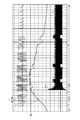
- FIG. 2 shows the relationship between the pulse signal Cr output from the crank angle sensor 7, the rotational speed R of the internal combustion engine 1, and the power consumption Pw of the ignition device 11, injector 15 and fuel pump 14.
- T1 indicates the initial stage of the recoil operation. Empirically, at T1, the operator is sensitive to the load. T2 indicates the middle stage and end stage of the recoil operation. Empirically, the operator is insensitive to the load at T2.
- T3 indicates a period during which the recoil operation is completed and the internal combustion engine 1 is rotated by the moment of inertia. Since the recoil operation is completed at T3, the operator does not feel a load.
- the control unit 9 supplies power from the generator 6 to the ignition device 11, the injector 15 and the fuel pump 14.
- the threshold value Rth is the rotation speed at which the internal combustion engine 1 can rotate independently.
- the threshold value Rth is, for example, the rotational speed at which the moment of inertia of the internal combustion engine 1 generates the moment of inertia that allows the internal combustion engine 1 to rotate independently. Electric power is not supplied to the ignition device 11, the injector 15, and the fuel pump 14 until the rotational speed R reaches the threshold value Rth. Therefore, the load that the operator feels through the recoil starter 5 is reduced. Further, since the operator is already insensitive to the load at the end of the recoil operation, even if power is supplied to the ignition device 11, the injector 15, and the fuel pump 14, the operator will not care about the load. .
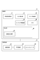
- FIG. 3 shows the function of the control unit 9 and the function of the power supply circuit 8.
- the rotational speed calculation unit 21 calculates and acquires the rotational speed based on the interval of the pulse signals output from the crank angle sensor 7.
- the crank angle sensor 7 outputs nine pulses every time the crankshaft 19 rotates 30 degrees, and does not output any pulses while it rotates 120 degrees thereafter. In particular, paying attention to the former pulse, the pulse interval becomes shorter as the rotational speed of the crankshaft 19 increases. This pulse interval represents the time required for the crankshaft 19 to rotate 30 degrees.
- the rotation speed calculation unit 21 measures the pulse interval t using a timer or a counter, and acquires the rotation speed R by calculating (360 degrees ⁇ 30 degrees) ⁇ t.
- the determination unit 20 determines whether the internal combustion engine 1 can rotate independently based on the rotational speed R.
- the rotation speed comparison unit 27 compares the rotation speed R with a threshold value Rth and determines whether the rotation speed R is equal to or greater than the threshold value Rth.
- the determination unit 20 may determine that the internal combustion engine 1 can rotate independently if the rotational speed R is equal to or greater than the threshold value Rth, and output an energization permission signal.
- the determination unit 20 determines that the internal combustion engine 1 cannot rotate independently and does not output an energization permission signal (or outputs an energization permission signal).
- the ignition control unit 23 starts energization to the ignition device 11 when the determination unit 20 outputs the energization permission signal, and does not execute energization to the ignition device 11 unless the determination unit 20 outputs the energization permission signal.
- the injector control unit 24 starts energization to the injector 15 when the determination unit 20 outputs the energization permission signal, and does not execute energization to the injector 15 unless the determination unit 20 outputs the energization permission signal.
- the pump control unit 25 starts energization of the fuel pump 14, and does not execute the energization of the fuel pump 14 unless the determination unit 20 outputs the energization permission signal.
- the memory 26 stores a threshold value Rth and the like.
- the memory 26 is a storage device including a RAM and a ROM.
- the start of energization is realized by switching a switch such as a relay or a semiconductor switch provided on a power line from the power supply circuit 8 to the ignition device 11, the injector 15, and the fuel pump 14 from off to on.
- this switch is provided in the power supply circuit 8 and is provided for each of the ignition device 11, the injector 15, and the fuel pump 14.
- the amount of fuel required by the internal combustion engine 1 during the operation period depends on the magnitude of the load that is operated by being supplied with electric power from the engine system 100. Therefore, the pump control unit 25 may perform PWM control on the energization time to the fuel pump 14 according to the magnitude of the load. That is, the length of the on period (on duty) of the pulse-shaped drive signal supplied to the fuel pump 14 may be variably controlled according to the magnitude of the load. This leads to a reduction in power consumption of the fuel pump 14 and a reduction in heat generation.
- the rectifier circuit 31 is a circuit that rectifies the alternating current generated by the generator 6.
- the smoothing circuit 32 is a circuit that smoothes the pulsating flow generated by the rectifying circuit 31 and generates a direct current. Thereby, for example, a DC voltage of 12V is generated.
- the control unit 9 may perform PWM control on the power supplied to the fuel pump 14 in accordance with the load on the generator 6 and the internal combustion engine 1.
- the DC / DC converter 35 is a circuit that converts the level of a DC voltage. For example, the DC / DC converter 35 converts a DC voltage of 12V into a DC voltage of 5V or 3.3V.
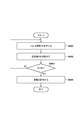
- FIG. 4 is a flowchart showing power control in the starting period.
- the control unit 9 executes the following processing.
- the rotation speed calculation unit 21 of the control unit 9 measures the pulse interval t using a timer or a counter. Note that the timer or counter may be provided outside the rotation speed calculation unit 21 as a detection unit or measurement unit for the pulse interval t.
- the rotation speed calculation unit 21 of the control unit 9 calculates the rotation speed R based on the measured pulse interval t. As shown in FIG.
- the pulse interval t between adjacent pulses from the first pulse to the ninth pulse is substantially the same, but the ninth pulse and the tenth pulse (1 in the second cycle).
- the pulse interval between the first and second pulses is extremely long. Therefore, the rotational speed calculation unit 21 calculates the rotational speed R by excluding extremely long pulse intervals.
- the rotation speed comparison unit 27 of the control unit 9 determines whether the rotation speed R acquired by the calculation is equal to or greater than the threshold value Rth read from the memory 26. If the rotational speed R is less than the threshold value Rth, the internal combustion engine 1 is not capable of autonomous rotation, and therefore the rotational speed comparison unit 27 returns to S401 and measures the next pulse interval t.
- the control unit 9 starts energization (power supply) to the ignition device 11, the injector 15, and the fuel pump 14.
- the control unit 9 is an auxiliary machine (ignition device 11, injector 15, and fuel) involved in fuel injection and ignition until the rotational speed R becomes equal to or higher than the specified rotational speed in the start-up period of the internal combustion engine 1 by the recoil starter 5.
- the power from the generator 6 is not supplied to the pump 14).
- the controller 9 supplies power from the generator to the ignition device 11, the injector 15, and the fuel pump 14 when the rotational speed R becomes equal to or higher than the specified rotational speed. That is, in the first period from when the recoil starter 5 is pulled until the rotational speed R becomes equal to or higher than the specified rotational speed, power is not supplied to the auxiliary machine, and the second speed after the rotational speed R becomes equal to or higher than the specified rotational speed. Power is supplied to the auxiliary machine during the period. As a result, the load felt by the recoil operator when the internal combustion engine 1 is started can be reduced.
- Example 2 Control unit and power supply circuit>
- whether to start energization (power supply) to the ignition device 11, the injector 15, and the fuel pump 14 is determined based on the rotational speed R.
- whether to start energization (power supply) to the ignition device 11, the injector 15, and the fuel pump 14 is determined based on whether or not the acceleration of the internal combustion engine 1 acquired from the pulse interval t is less than a threshold value.
- the operator holds the handle of the recoil starter 5 and pulls it at once. Further, since the length of the cable (string) connected to the handle is a fixed length, the acceleration of the crankshaft 19 starts to decrease midway. According to FIG.
- FIG. 5 shows the function of the control unit 9 and the function of the power supply circuit 8.
- the acceleration calculator 22 measures the pulse interval t of the pulse signal output from the crank angle sensor 7 and calculates and acquires the acceleration a of the crankshaft 19 based on the pulse interval t.
- the acceleration calculation unit 22 may calculate the acceleration a based on the rotation speeds Ri-1 and Ri detected by the rotation speed calculation unit 21 (i is a pulse number, 1 to 9). This is because the acceleration a is a parameter indicating the rate of increase in the rotational speed.
- the acceleration calculation unit 22 may calculate the acceleration a by differentiating the rotation number R detected by the rotation number calculation unit 21.
- the acceleration comparison unit 28 determines whether or not the acceleration a is equal to or greater than the specified acceleration ath. For example, the acceleration comparison unit 28 does not output an energization permission signal if the acceleration a is equal to or greater than a specified acceleration at. On the other hand, if the acceleration a is less than the specified acceleration ath, the acceleration comparison unit 28 outputs an energization permission signal.
- the ignition control unit 23 does not supply power from the generator 6 to the ignition device 11 unless the energization permission signal is output.
- the injector control unit 24 does not supply power from the generator 6 to the injector 15 unless the energization permission signal is output.
- the pump control unit 25 does not supply power from the generator 6 to the fuel pump 14.
- the acceleration comparison unit 28 outputs an energization permission signal.
- the control unit 9 supplies power from the generator 6 to the ignition device 11, the injector 15, and the fuel pump 14.
- FIG. 6 is a flowchart showing power control in the starting period.
- the control unit 9 executes the following processing.
- the acceleration calculation unit 22 of the control unit 9 measures the pulse interval t using a timer or a counter. Note that the timer or counter may be provided outside the acceleration calculation unit 22 as a detection unit or measurement unit for the pulse interval t.
- the acceleration calculation unit 22 of the control unit 9 calculates the acceleration a based on the measured pulse interval t. The acceleration may be calculated based on the rotation speed detected by the rotation speed calculation unit 21. As shown in FIG.
- the acceleration calculation unit 22 calculates the acceleration a excluding extremely long pulse intervals.
- step S ⁇ b> 603 the acceleration comparison unit 28 of the control unit 9 determines whether the acceleration “a” acquired by the calculation is less than the specified acceleration “ath” read from the memory 26. If the acceleration a is not less than the specified acceleration ath (that is, if the acceleration a is equal to or greater than the specified acceleration ath), the acceleration comparison unit 28 returns to S601 and measures the next pulse interval t.
- the acceleration comparing unit 28 proceeds to S604.
- the control unit 9 starts energization (power supply) to the ignition device 11, the injector 15, and the fuel pump 14.
- the control unit 9 supplies power from the generator 6 to the ignition device 11, the injector 15, and the fuel pump 14. Do not supply.
- the acceleration a is a parameter indicating an increase in the rotational speed R detected by the rotational speed calculation unit 21. That is, the control unit 9 does not supply power from the generator 6 to the ignition device 11, the injector 15, and the fuel pump 14 while the rotational speed R is increasing.
- the acceleration a is no more than the specified acceleration ath, the power supply from the generator 6 to the ignition device 11, the injector 15, and the fuel pump 14 is started.
- control unit 9 starts supplying power when the increase in the rotational speed R is completed.
- the control unit 9 starts supplying power when the increase in the rotational speed R is completed.
- Example 3 Control unit and power supply circuit> In the third embodiment, whether to supply power is determined in consideration of both the rotational speed R and the acceleration a.
- FIG. 7 shows the function of the control unit 9 and the function of the power supply circuit 8. In FIG. 7, the same reference numerals are assigned to items common to FIGS.
- the comprehensive determination unit 29 determines whether the rotational speed R is less than the threshold value Rth or whether the acceleration a is equal to or greater than the specified acceleration ath. If the rotational speed R is less than the threshold value Rth or if the acceleration a is equal to or greater than the specified acceleration ath, the control unit 9 does not supply power from the generator 6 to the ignition device 11, the injector 15, and the fuel pump 14. On the other hand, if the rotational speed R is equal to or greater than the threshold value Rth and the acceleration a is less than the specified acceleration ath, the control unit 9 supplies power from the generator 6 to the ignition device 11, the injector 15, and the fuel pump 14. .
- FIG. 8 is a flowchart showing power control in the starting period.
- the control unit 9 executes the following processing. Processes that have already been described are briefly described.
- step S801 the rotation speed calculation unit 21 of the control unit 9 measures the pulse interval t using a timer or a counter.
- step S802 the rotation speed calculation unit 21 of the control unit 9 calculates the rotation speed R.
- step S803 the acceleration calculation unit 22 of the control unit 9 calculates the acceleration a.
- the rotation speed comparison unit 27 of the control unit 9 determines whether the rotation speed R is greater than or equal to the threshold value Rth.
- the control unit 9 determines whether the acceleration a is less than the specified acceleration ath. If the acceleration a is not less than the specified acceleration ath (if the acceleration a is greater than or equal to the specified acceleration ath), the acceleration comparison unit 28 returns to S801. On the other hand, if the acceleration a is less than the specified acceleration ath (if the acceleration a is not greater than or equal to the specified acceleration ath), the acceleration comparing unit 28 proceeds to S806. In S806, the control unit 9 starts energization (power supply) to the ignition device 11, the injector 15, and the fuel pump 14.
- the control unit 9 supplies power from the generator 6 to the ignition device 11, the injector 15, and the fuel pump 14. Do not supply.
- the control unit 9 supplies power from the generator 6 to the ignition device 11, the injector 15, and the fuel pump 14. .
- the engine system 100 includes a fuel tank 13 that contains fuel, an internal combustion engine 1, a generator 6 that is driven by the internal combustion engine 1 to generate electric power, and a recoil starter 5 that starts the internal combustion engine 1.
- a control unit 9 that operates with the electric power generated by the generator 6; an injector 15 that operates with the electric power generated by the generator 6 and that is controlled by the control unit 9 and supplies fuel to the internal combustion engine 1;
- a fuel pump 14 that is operated by electric power generated by the generator 6 and that is controlled by the control unit 9 and that supplies fuel stored in the fuel tank 13 to the injector 15, and fuel compressed in the internal combustion engine 1
- An ignition device 11 that ignites and a detection unit that detects the rotational speed R of the internal combustion engine 1 are provided.
- the crank angle sensor 7 is an example of a detection unit that detects the rotational speed R of the internal combustion engine 1.
- the control unit 9 determines whether or not the internal combustion engine 1 can rotate independently based on the rotational speed R in the starting period of the internal combustion engine 1 by the recoil starter 5.
- the control unit 9 does not supply power from the generator 6 to the ignition device 11, the injector 15, and the fuel pump 14 unless the internal combustion engine 1 can rotate independently.
- the control unit 9 supplies power from the generator 6 to the ignition device 11, the injector 15, and the fuel pump 14 if the internal combustion engine 1 can rotate independently. As a result, the load felt by the recoil operator when the internal combustion engine 1 is started can be reduced.
- the control unit 9 performs the ignition device 11 and the injector 15 until the rotational speed R becomes equal to or higher than a specified rotational speed (for example, threshold value Rth) at which the internal combustion engine 1 can rotate independently. And the electric power from the generator 6 is not supplied to the fuel pump 14. Further, the control unit 9 supplies power from the generator 6 to the ignition device 11, the injector 15, and the fuel pump 14 when the rotational speed R becomes equal to or higher than the specified rotational speed. As a result, the load felt by the recoil operator when the internal combustion engine 1 is started can be reduced.
- a specified rotational speed for example, threshold value Rth
- control unit 9 supplies the ignition device 11, the injector 15, and the fuel pump 14 from the generator 6 while the rotational speed R detected by the detection unit is increasing in the starting period of the internal combustion engine 1 by the recoil starter 5. It is not necessary to supply the power.
- control part 9 may supply the electric power from the generator 6 to the ignition device 11, the injector 15, and the fuel pump 14 when the increase in the rotation speed R is completed.
- control unit 9 obtains the acceleration a from the rotational speed R detected by the detection unit in the starting period of the internal combustion engine 1 by the recoil starter 5, and when the acceleration a is equal to or greater than the specified acceleration ath, the ignition device 11
- the electric power from the generator 6 may not be supplied to the injector 15 and the fuel pump 14.
- control part 9 may supply the electric power from the generator 6 to the ignition device 11, the injector 15, and the fuel pump 14 when the acceleration a is not equal to or higher than the specified acceleration ath.
- the control unit 9 obtains the acceleration a from the rotation speed R detected by the detection unit, and the rotation speed R is less than a specified rotation speed at which the internal combustion engine 1 can rotate independently, or the acceleration a is equal to or higher than the specified acceleration. If so, it is not necessary to supply power from the generator 6 to the ignition device 11, the injector 15, and the fuel pump 14. Further, the control unit 9 supplies a generator to the ignition device 11, the injector 15 and the fuel pump 14 if the rotational speed R is equal to or higher than a predetermined rotational speed at which the internal combustion engine 1 can rotate independently and the acceleration is less than the predetermined acceleration. You may supply the electric power from 6.
- control unit 9 controls the ignition device 11, the injector 15, and the injector 15 during a period from the start of operation of the recoil starter 5 until the rotational speed R becomes equal to or higher than a predetermined rotational speed at which the internal combustion engine 1 can rotate independently. It is not necessary to supply power from the generator 6 to the fuel pump 14.
- the controller 9 may start supplying power from the generator 6 to the ignition device 11, the injector 15, and the fuel pump 14 after the rotational speed R becomes equal to or higher than the specified rotational speed.
Landscapes
- Engineering & Computer Science (AREA)
- Chemical & Material Sciences (AREA)
- Combustion & Propulsion (AREA)
- Mechanical Engineering (AREA)
- General Engineering & Computer Science (AREA)
- Physics & Mathematics (AREA)
- Electromagnetism (AREA)
- Combined Controls Of Internal Combustion Engines (AREA)
- Electrical Control Of Air Or Fuel Supplied To Internal-Combustion Engine (AREA)
- Ignition Installations For Internal Combustion Engines (AREA)
Abstract
エンジンシステムは、燃料タンク、内燃エンジン、発電機、リコイルスターター、制御部、インジェクタ、燃料ポンプ、点火装置、および、内燃エンジンの回転数などを検知する検知部を有する。制御部は、リコイルスターターによる内燃エンジンの始動期において、回転数などに基づき内燃エンジンが自立回転可能かどうかを判定する。内燃エンジンが自立回転可能でなければ点火装置、インジェクタおよび燃料ポンプには電力が供給されない。内燃エンジンが自立回転可能となるとこれらに電力が供給される。
Description
本発明は電子燃料噴射制御システムおよびエンジンシステムに関する。
内燃エンジンにより発電機を駆動して電力を生成するエンジンシステムは送電網が普及していない地域や商用電源の停電時に有用な電源である。特許文献1によれば、手動操作式のエンジン始動装置であるリコイルスターターを備えたエンジンシステムにおいて始動時に不足する電力を補うためにバックアップ電池を設けることが提案されている。
特許文献1の手法ではバックアップ電池を設けることで電子式燃料噴射装置に十分な電力を供給している。しかし、バックアップ電池を設けることでエンジンシステムの製造コストが増加してしまう。また、バックアップ電池を設けずにリコイル操作者の動力だけに任せると、操作者には大きな仕事を課すことになってしまう。つまり、操作者はエンジンを始動するために大きな荷重を感じることとなる。そこで、本発明は、内燃エンジンの始動時にリコイル操作者が感じる荷重を軽減することを目的とする。
本発明によれば、たとえば、
燃料を収容する燃料タンクと、
内燃エンジンと、
前記内燃エンジンにより駆動されて発電する発電機と、
前記内燃エンジンを始動するリコイルスターターと、
前記発電機により生成された電力により動作する制御部と、
前記発電機により生成された電力により動作し、かつ、前記制御部により制御され、前記内燃エンジンに燃料を供給するインジェクタと、
前記発電機により生成された電力により動作し、かつ、前記制御部により制御され、前記燃料タンクに収容されている燃料を前記インジェクタに供給する燃料ポンプと、
前記内燃エンジンにおいて圧縮された前記燃料に点火する点火装置と、
前記内燃エンジンの回転数を検知する検知部と
を有し、
前記制御部は、前記リコイルスターターによる前記内燃エンジンの始動期において、前記回転数に基づき前記内燃エンジンが自立回転可能かどうかを判定し、前記内燃エンジンが自立回転可能でなければ前記点火装置、前記インジェクタおよび前記燃料ポンプに前記発電機からの電力を供給せず、前記内燃エンジンが自立回転可能であれば前記点火装置、前記インジェクタおよび前記燃料ポンプに前記発電機からの電力を供給することを特徴とするバッテリーレスのエンジンシステムが提供される。
燃料を収容する燃料タンクと、
内燃エンジンと、
前記内燃エンジンにより駆動されて発電する発電機と、
前記内燃エンジンを始動するリコイルスターターと、
前記発電機により生成された電力により動作する制御部と、
前記発電機により生成された電力により動作し、かつ、前記制御部により制御され、前記内燃エンジンに燃料を供給するインジェクタと、
前記発電機により生成された電力により動作し、かつ、前記制御部により制御され、前記燃料タンクに収容されている燃料を前記インジェクタに供給する燃料ポンプと、
前記内燃エンジンにおいて圧縮された前記燃料に点火する点火装置と、
前記内燃エンジンの回転数を検知する検知部と
を有し、
前記制御部は、前記リコイルスターターによる前記内燃エンジンの始動期において、前記回転数に基づき前記内燃エンジンが自立回転可能かどうかを判定し、前記内燃エンジンが自立回転可能でなければ前記点火装置、前記インジェクタおよび前記燃料ポンプに前記発電機からの電力を供給せず、前記内燃エンジンが自立回転可能であれば前記点火装置、前記インジェクタおよび前記燃料ポンプに前記発電機からの電力を供給することを特徴とするバッテリーレスのエンジンシステムが提供される。
本発明によれば、内燃エンジンの始動時にリコイル操作者が感じる荷重を軽減することが可能となる。
本発明のその他の特徴及び利点は、添付図面を参照とした以下の説明により明らかになるであろう。なお、添付図面においては、同じ若しくは同様の構成には、同じ参照番号を付す。
添付図面は明細書に含まれ、その一部を構成し、本発明の実施の形態を示し、その記述と共に本発明の原理を説明するために用いられる。
エンジンシステムを示す概略図
回転数と電力供給の開始タイミングとの関係を示す図
制御部と電源回路を示すブロック図
電力制御を示すフローチャート
制御部と電源回路を示すブロック図
電力制御を示すフローチャート
制御部と電源回路を示すブロック図
電力制御を示すフローチャート
添付図面は明細書に含まれ、その一部を構成し、本発明の実施の形態を示し、その記述と共に本発明の原理を説明するために用いられる。
<エンジンシステム>
図1はバッテリーレスのエンジンシステム100を示す概略図である。エンジンシステム100は電子燃料噴射制御システムと呼ばれてもよい。内燃エンジン1は4ストローク式のエンジンである。クランクケース2にはクランクシャフト19が収容されている。クランクシャフト19が回転することでコンロッド3に連結されたピストン4をシリンダ内で上下運動させる。クランクシャフト19には内燃エンジン1を始動するためのリコイルスターター5が連結されている。リコイル操作者はリコイルスターター5の把手を掴んで引っ張ることでクランクシャフト19を回転させる。クランクシャフト19には発電機6が連結されており、クランクシャフト19が回転することで発電機6のローターが回転して発電する。クランクシャフト19のクランク角はクランク角センサー7によって検知される。クランク角センサー7は、たとえば、クランクシャフト19に連結されたフライホイールに設けられたマグネットの磁気を検知するホール素子などであってもよい。電源回路8は発電機6により生成された交流を直流に変換する回路や、直流電圧のレベルを変換する回路などを有している。電源回路8は発電機6により生成された電力を制御部9に供給する。なお、リコイルスターター5によってクランクシャフト19が回転すると、発電機6は制御部9が動作するのに十分な電力を発生する。制御部9はエンジン制御ユニット(ECU)であり、電源回路8から点火装置11、燃料ポンプ14、インジェクタ15およびスロットルモータ16などに供給する電力を制御する。点火装置11は、点火プラグ12に火花放電させるための点火電力を供給する。燃料タンク13は燃料を収容する容器である。燃料ポンプ14は燃料タンク13に収容されている燃料をインジェクタ15に供給するポンプである。図1において燃料ポンプ14は燃料タンク内に設けられている。スロットルモータ16は空気流入量を制御するためのモータである。吸気バルブ17はクランクシャフト19の回転運動を上下運動に変換するカム等によって開閉するバルブである。吸気バルブ17は吸気行程において開き、圧縮行程、膨張行程および排気行程では基本的に閉じている。排気バルブ18はクランクシャフト19の回転運動を上下運動に変換するカム等によって開閉するバルブである。排気バルブ18は排気行程において開き、圧縮行程、膨張行程および吸気行程においては基本的に閉じている。排気から吸気への遷移をスムーズにするために、吸気バルブ17と排気バルブ18とが同時に開く期間が設けられてもよい(オーバーラップ)。
図1はバッテリーレスのエンジンシステム100を示す概略図である。エンジンシステム100は電子燃料噴射制御システムと呼ばれてもよい。内燃エンジン1は4ストローク式のエンジンである。クランクケース2にはクランクシャフト19が収容されている。クランクシャフト19が回転することでコンロッド3に連結されたピストン4をシリンダ内で上下運動させる。クランクシャフト19には内燃エンジン1を始動するためのリコイルスターター5が連結されている。リコイル操作者はリコイルスターター5の把手を掴んで引っ張ることでクランクシャフト19を回転させる。クランクシャフト19には発電機6が連結されており、クランクシャフト19が回転することで発電機6のローターが回転して発電する。クランクシャフト19のクランク角はクランク角センサー7によって検知される。クランク角センサー7は、たとえば、クランクシャフト19に連結されたフライホイールに設けられたマグネットの磁気を検知するホール素子などであってもよい。電源回路8は発電機6により生成された交流を直流に変換する回路や、直流電圧のレベルを変換する回路などを有している。電源回路8は発電機6により生成された電力を制御部9に供給する。なお、リコイルスターター5によってクランクシャフト19が回転すると、発電機6は制御部9が動作するのに十分な電力を発生する。制御部9はエンジン制御ユニット(ECU)であり、電源回路8から点火装置11、燃料ポンプ14、インジェクタ15およびスロットルモータ16などに供給する電力を制御する。点火装置11は、点火プラグ12に火花放電させるための点火電力を供給する。燃料タンク13は燃料を収容する容器である。燃料ポンプ14は燃料タンク13に収容されている燃料をインジェクタ15に供給するポンプである。図1において燃料ポンプ14は燃料タンク内に設けられている。スロットルモータ16は空気流入量を制御するためのモータである。吸気バルブ17はクランクシャフト19の回転運動を上下運動に変換するカム等によって開閉するバルブである。吸気バルブ17は吸気行程において開き、圧縮行程、膨張行程および排気行程では基本的に閉じている。排気バルブ18はクランクシャフト19の回転運動を上下運動に変換するカム等によって開閉するバルブである。排気バルブ18は排気行程において開き、圧縮行程、膨張行程および吸気行程においては基本的に閉じている。排気から吸気への遷移をスムーズにするために、吸気バルブ17と排気バルブ18とが同時に開く期間が設けられてもよい(オーバーラップ)。
ところで、制御部9や燃料ポンプ14、点火装置11、インジェクタ15の消費電力の合計値は数十ワットに達することがある。この電力を、バックアップ電池を用いることなく発電機6のみで賄う場合、大きなリコイル動力が必要となる。つまり、リコイル操作者には力仕事が要求される。そこで、制御部9は、リコイルスターター5による内燃エンジン1の始動期において、点火装置11、インジェクタ15および燃料ポンプ14への電力供給を制限することで操作者が感じる荷重を軽減する。たとえば、制御部9は、回転数や加速度を参照し、内燃エンジン1が自立回転可能でなければ、点火装置11、インジェクタ15および燃料ポンプ14に発電機6からの電力を供給しない。制御部9は、内燃エンジン1が自立回転可能であれば点火装置11、インジェクタ15および燃料ポンプ14に発電機6からの電力を供給する。これにより、始動期においてリコイル操作者か感じる荷重が軽減される。
<電力供給のタイミング>
図2はクランク角センサー7が出力するパルス信号Cr、内燃エンジン1の回転数Rおよび点火装置11、インジェクタ15および燃料ポンプ14の消費電力Pwとの関係を示している。T1はリコイル操作の初期を示している。経験的にT1において操作者は荷重に対して敏感である。T2はリコイル操作の中期および終了期を示している。経験的にT2において操作者は荷重に鈍感になっている。T3はリコイル操作が終了し、内燃エンジン1が慣性モーメントにより回転している期間を示している。T3ではリコイル操作が終了しているため、操作者は荷重を感じない。
図2はクランク角センサー7が出力するパルス信号Cr、内燃エンジン1の回転数Rおよび点火装置11、インジェクタ15および燃料ポンプ14の消費電力Pwとの関係を示している。T1はリコイル操作の初期を示している。経験的にT1において操作者は荷重に対して敏感である。T2はリコイル操作の中期および終了期を示している。経験的にT2において操作者は荷重に鈍感になっている。T3はリコイル操作が終了し、内燃エンジン1が慣性モーメントにより回転している期間を示している。T3ではリコイル操作が終了しているため、操作者は荷重を感じない。
図3によれば、制御部9は回転数Rが規定回転数(閾値Rth)以上になると、点火装置11、インジェクタ15および燃料ポンプ14に発電機6からの電力を供給する。閾値Rthは内燃エンジン1が自立回転可能な回転数である。閾値Rthは、たとえば、内燃エンジン1の慣性モーメントが内燃エンジン1を自立回転可能とする慣性モーメントを生む回転数である。回転数Rが閾値Rthに達するまでは点火装置11、インジェクタ15および燃料ポンプ14に電力が供給されない。そのため、操作者がリコイルスターター5を通じて感じる荷重が軽減される。また、リコイル操作の終了期ではすでに操作者が荷重に鈍感になっているため、点火装置11、インジェクタ15および燃料ポンプ14に電力を供給しても、操作者は荷重を気にしないであろう。
●実施例1
<制御部と電源回路>
図3は制御部9の機能と電源回路8の機能を示している。制御部9において回転数演算部21はクランク角センサー7から出力されるパルス信号の間隔に基づき回転数を演算して取得する。クランク角センサー7はクランクシャフト19が30度回転するごとに9個のパルスを出力し、その後120度回転する間はパルスを出力しない。とりわけ、前者のパルスに着目すると、クランクシャフト19の回転数が上昇すると、パルス間隔が短くなって行く。このパルス間隔はクランクシャフト19が30度回転するのに要した時間を表している。したがって、回転数演算部21はタイマーやカウンタを用いてパルス間隔tを測定し、(360度÷30度)÷tを演算することで回転数Rを取得する。判定部20は、回転数Rに基づき内燃エンジン1が自立回転可能かどうかを判定する。回転数比較部27は回転数Rと閾値Rthとを比較し、回転数Rが閾値Rth以上かどうかを判定する。判定部20は、回転数Rが閾値Rth以上であれば内燃エンジン1が自立回転可能と判定して通電許可信号を出力してもよい。または、判定部20は、回転数Rが閾値Rth未満であれば内燃エンジン1が自立回転不可能と判定して通電許可信号を出力しない(あるいは通電不許可信号を出力する)。点火制御部23は判定部20が通電許可信号を出力すると、点火装置11への通電を開始し、判定部20が通電許可信号を出力していなければ、点火装置11への通電を実行しない。インジェクタ制御部24は判定部20が通電許可信号を出力すると、インジェクタ15への通電を開始し、判定部20が通電許可信号を出力していなければ、インジェクタ15への通電を実行しない。ポンプ制御部25は判定部20が通電許可信号を出力すると、燃料ポンプ14への通電を開始し、判定部20が通電許可信号を出力していなければ、燃料ポンプ14への通電を実行しない。なお、メモリ26は閾値Rthなどを記憶している。メモリ26はRAMやROMなどを含む記憶装置である。通電の開始は、電源回路8から点火装置11、インジェクタ15、燃料ポンプ14への電力線に設けられたリレーや半導体スイッチなどのスイッチをオフからオンに切り替えることで実現される。たとえば、このスイッチは電源回路8の内部に設けられ、かつ、点火装置11、インジェクタ15、燃料ポンプ14のそれぞれに対して設けられる。
<制御部と電源回路>
図3は制御部9の機能と電源回路8の機能を示している。制御部9において回転数演算部21はクランク角センサー7から出力されるパルス信号の間隔に基づき回転数を演算して取得する。クランク角センサー7はクランクシャフト19が30度回転するごとに9個のパルスを出力し、その後120度回転する間はパルスを出力しない。とりわけ、前者のパルスに着目すると、クランクシャフト19の回転数が上昇すると、パルス間隔が短くなって行く。このパルス間隔はクランクシャフト19が30度回転するのに要した時間を表している。したがって、回転数演算部21はタイマーやカウンタを用いてパルス間隔tを測定し、(360度÷30度)÷tを演算することで回転数Rを取得する。判定部20は、回転数Rに基づき内燃エンジン1が自立回転可能かどうかを判定する。回転数比較部27は回転数Rと閾値Rthとを比較し、回転数Rが閾値Rth以上かどうかを判定する。判定部20は、回転数Rが閾値Rth以上であれば内燃エンジン1が自立回転可能と判定して通電許可信号を出力してもよい。または、判定部20は、回転数Rが閾値Rth未満であれば内燃エンジン1が自立回転不可能と判定して通電許可信号を出力しない(あるいは通電不許可信号を出力する)。点火制御部23は判定部20が通電許可信号を出力すると、点火装置11への通電を開始し、判定部20が通電許可信号を出力していなければ、点火装置11への通電を実行しない。インジェクタ制御部24は判定部20が通電許可信号を出力すると、インジェクタ15への通電を開始し、判定部20が通電許可信号を出力していなければ、インジェクタ15への通電を実行しない。ポンプ制御部25は判定部20が通電許可信号を出力すると、燃料ポンプ14への通電を開始し、判定部20が通電許可信号を出力していなければ、燃料ポンプ14への通電を実行しない。なお、メモリ26は閾値Rthなどを記憶している。メモリ26はRAMやROMなどを含む記憶装置である。通電の開始は、電源回路8から点火装置11、インジェクタ15、燃料ポンプ14への電力線に設けられたリレーや半導体スイッチなどのスイッチをオフからオンに切り替えることで実現される。たとえば、このスイッチは電源回路8の内部に設けられ、かつ、点火装置11、インジェクタ15、燃料ポンプ14のそれぞれに対して設けられる。
運転期において内燃エンジン1が必要とする燃料の量はエンジンシステム100から電力を供給されて動作する負荷の大きさに依存する。したがって、ポンプ制御部25は、負荷の大きさに応じて燃料ポンプ14への通電時間をPWM制御してもよい。つまり、負荷の大きさに応じて燃料ポンプ14に供給されるパルス状の駆動信号のオン期間(オンデューティ)の長さが可変制御されてもよい。これは燃料ポンプ14の消費電力の低減と発熱量の低減をもたらす。
電源回路8において整流回路31は発電機6により生成された交流を整流する回路である。平滑回路32は整流回路31により生成された脈流を平滑して直流を生成する回路である。これにより、たとえば、12Vの直流電圧が生成される。制御部9は発電機6や内燃エンジン1の負荷に応じて燃料ポンプ14に供給される電力をPWM制御してもよい。DC/DCコンバータ35は直流電圧のレベルを変換する回路である。たとえば、DC/DCコンバータ35は、12Vの直流電圧を5Vや3.3Vの直流電圧に変換する。
<フローチャート>
図4は始動期における電力制御を示すフローチャートである。制御部9は電源回路8を通じて発電機6により生成された電力の供給を受けて起動すると、以下の処理を実行する。
・S401で制御部9の回転数演算部21はタイマーやカウンタを用いてパルス間隔tを測定する。なお、タイマーやカウンタはパルス間隔tの検知部または測定部として回転数演算部21の外側に設けられてもよい。
・S402で制御部9の回転数演算部21は測定されたパルス間隔tに基づき回転数Rを演算する。なお、図3が示すように、1番目のパルスから9番目のパルスまでにおいて隣り合ったパルスのパルス間隔tはほぼ同じであるが、9番目のパルスと10番目のパルス(二周期目の1番目のパルス)との間のパルス間隔は極端に長い。そのため、回転数演算部21は極端に長いパルス間隔を除外して回転数Rを算出する。
・S403で制御部9の回転数比較部27は、演算により取得された回転数Rがメモリ26から読み出された閾値Rth以上かどうかを判定する。回転数Rが閾値Rth未満であれば内燃エンジン1は自立回転可能ではないため、回転数比較部27はS401に戻り、次のパルス間隔tを測定する。一方で、回転数Rが閾値Rth以上であれば内燃エンジン1は自立回転可能なため、回転数比較部27はS404に進む。
・S404で制御部9は点火装置11、インジェクタ15および燃料ポンプ14への通電(電力供給)を開始する。
図4は始動期における電力制御を示すフローチャートである。制御部9は電源回路8を通じて発電機6により生成された電力の供給を受けて起動すると、以下の処理を実行する。
・S401で制御部9の回転数演算部21はタイマーやカウンタを用いてパルス間隔tを測定する。なお、タイマーやカウンタはパルス間隔tの検知部または測定部として回転数演算部21の外側に設けられてもよい。
・S402で制御部9の回転数演算部21は測定されたパルス間隔tに基づき回転数Rを演算する。なお、図3が示すように、1番目のパルスから9番目のパルスまでにおいて隣り合ったパルスのパルス間隔tはほぼ同じであるが、9番目のパルスと10番目のパルス(二周期目の1番目のパルス)との間のパルス間隔は極端に長い。そのため、回転数演算部21は極端に長いパルス間隔を除外して回転数Rを算出する。
・S403で制御部9の回転数比較部27は、演算により取得された回転数Rがメモリ26から読み出された閾値Rth以上かどうかを判定する。回転数Rが閾値Rth未満であれば内燃エンジン1は自立回転可能ではないため、回転数比較部27はS401に戻り、次のパルス間隔tを測定する。一方で、回転数Rが閾値Rth以上であれば内燃エンジン1は自立回転可能なため、回転数比較部27はS404に進む。
・S404で制御部9は点火装置11、インジェクタ15および燃料ポンプ14への通電(電力供給)を開始する。
このように制御部9は、リコイルスターター5による内燃エンジン1の始動期において、回転数Rが規定回転数以上になるまでは燃料噴射と点火に関与する補機(点火装置11、インジェクタ15および燃料ポンプ14)に発電機6からの電力を供給しない。制御部9は、回転数Rが規定回転数以上になると点火装置11、インジェクタ15および燃料ポンプ14に発電機からの電力を供給する。つまり、リコイルスターター5の引き始めから回転数Rが規定回転数以上になるまでの第一期間においては補機に電力が供給されず、回転数Rが規定回転数以上になった後の第二期間において補機に電力が供給される。これにより内燃エンジン1の始動時にリコイル操作者が感じる荷重を軽減することが可能となる。
●実施例2
<制御部と電源回路>
実施例1では回転数Rに基づいて点火装置11、インジェクタ15および燃料ポンプ14への通電(電力供給)を開始するかどうかが判定されていた。実施例2ではパルス間隔tから取得された内燃エンジン1の加速度が閾値未満かどうかに基づいて点火装置11、インジェクタ15および燃料ポンプ14への通電(電力供給)を開始するかどうかが判定される。一般には操作者はリコイルスターター5の把手を握って一気に引っ張る。また、把手に接続されたケーブル(紐)の長さは一定の長さであるため、クランクシャフト19の加速度は途中で減少を開始する。図3によればほぼ操作の開始から一定の加速度が継続し、回転数Rが閾値Rthに達したころには加速度が低下し始めている。したがって、クランクシャフト19の加速度に基づき、内燃エンジン1が自立回転可能かどうかまたは点火装置11、インジェクタ15および燃料ポンプ14への通電(電力供給)を開始すべきかどうかを判定できる。
<制御部と電源回路>
実施例1では回転数Rに基づいて点火装置11、インジェクタ15および燃料ポンプ14への通電(電力供給)を開始するかどうかが判定されていた。実施例2ではパルス間隔tから取得された内燃エンジン1の加速度が閾値未満かどうかに基づいて点火装置11、インジェクタ15および燃料ポンプ14への通電(電力供給)を開始するかどうかが判定される。一般には操作者はリコイルスターター5の把手を握って一気に引っ張る。また、把手に接続されたケーブル(紐)の長さは一定の長さであるため、クランクシャフト19の加速度は途中で減少を開始する。図3によればほぼ操作の開始から一定の加速度が継続し、回転数Rが閾値Rthに達したころには加速度が低下し始めている。したがって、クランクシャフト19の加速度に基づき、内燃エンジン1が自立回転可能かどうかまたは点火装置11、インジェクタ15および燃料ポンプ14への通電(電力供給)を開始すべきかどうかを判定できる。
図5は制御部9の機能と電源回路8の機能を示している。図5において図3と共通する事項には同一の参照番号が付与されている。加速度演算部22はクランク角センサー7から出力されるパルス信号のパルス間隔tを測定し、パルス間隔tに基づきクランクシャフト19の加速度aを演算して取得する。なお、加速度演算部22は回転数演算部21により検知された回転数Ri-1とRiとに基づき加速度aを演算してもよい(iはパルスの番号であり、1ないし9)。これは加速度aが回転数の増加率を示すパラメータだからである。このように加速度演算部22は回転数演算部21により検知された回転数Rを微分することで加速度aを演算してもよい。加速度比較部28は加速度aが規定加速度ath以上かどうかを判定する。たとえば、加速度比較部28は加速度aが規定加速度ath以上であれば、通電許可信号を出力しない。一方で、加速度比較部28は加速度aが規定加速度ath未満であれば、通電許可信号を出力する。点火制御部23は通電許可信号が出力されていなければ、点火装置11に発電機6からの電力を供給しない。インジェクタ制御部24は通電許可信号が出力されていなければ、インジェクタ15に発電機6からの電力を供給しない。ポンプ制御部25は通電許可信号が出力されていなければ、燃料ポンプ14に発電機6からの電力を供給しない。加速度aが規定加速度ath以上でなくなると、加速度比較部28は通電許可信号を出力する。これにより、制御部9は点火装置11、インジェクタ15および燃料ポンプ14に発電機6からの電力を供給する。
<フローチャート>
図6は始動期における電力制御を示すフローチャートである。制御部9は電源回路8を通じて発電機6により生成された電力の供給を受けて起動すると、以下の処理を実行する。
・S601で制御部9の加速度演算部22はタイマーやカウンタを用いてパルス間隔tを測定する。なお、タイマーやカウンタはパルス間隔tの検知部または測定部として加速度演算部22の外側に設けられてもよい。
・S602で制御部9の加速度演算部22は測定されたパルス間隔tに基づき加速度aを演算する。回転数演算部21が検知した回転数に基づき加速度が演算されてもよい。図3が示すように、1番目のパルスから9番目のパルスまでにおいて隣り合ったパルスのパルス間隔tはほぼ同じであるが、9番目のパルスと10番目のパルス(二周期目の1番目のパルス)との間のパルス間隔は極端に長い。そのため、加速度演算部22は極端に長いパルス間隔を除外して加速度aを算出する。
・S603で制御部9の加速度比較部28は、演算により取得された加速度aがメモリ26から読み出された規定加速度ath未満であるかどうかを判定する。加速度aが規定加速度ath未満でなければ(つまり、加速度aが規定加速度ath以上であれば)、加速度比較部28はS601に戻り、次のパルス間隔tを測定する。一方で、加速度aが規定加速度ath未満となれば(加速度aが規定加速度ath以上でなくなれば)、加速度比較部28はS604に進む。
・S604で制御部9は点火装置11、インジェクタ15および燃料ポンプ14への通電(電力供給)を開始する。
図6は始動期における電力制御を示すフローチャートである。制御部9は電源回路8を通じて発電機6により生成された電力の供給を受けて起動すると、以下の処理を実行する。
・S601で制御部9の加速度演算部22はタイマーやカウンタを用いてパルス間隔tを測定する。なお、タイマーやカウンタはパルス間隔tの検知部または測定部として加速度演算部22の外側に設けられてもよい。
・S602で制御部9の加速度演算部22は測定されたパルス間隔tに基づき加速度aを演算する。回転数演算部21が検知した回転数に基づき加速度が演算されてもよい。図3が示すように、1番目のパルスから9番目のパルスまでにおいて隣り合ったパルスのパルス間隔tはほぼ同じであるが、9番目のパルスと10番目のパルス(二周期目の1番目のパルス)との間のパルス間隔は極端に長い。そのため、加速度演算部22は極端に長いパルス間隔を除外して加速度aを算出する。
・S603で制御部9の加速度比較部28は、演算により取得された加速度aがメモリ26から読み出された規定加速度ath未満であるかどうかを判定する。加速度aが規定加速度ath未満でなければ(つまり、加速度aが規定加速度ath以上であれば)、加速度比較部28はS601に戻り、次のパルス間隔tを測定する。一方で、加速度aが規定加速度ath未満となれば(加速度aが規定加速度ath以上でなくなれば)、加速度比較部28はS604に進む。
・S604で制御部9は点火装置11、インジェクタ15および燃料ポンプ14への通電(電力供給)を開始する。
このように、制御部9は、リコイルスターター5による内燃エンジン1の始動期において、加速度aが規定加速度ath以上であるときは、点火装置11、インジェクタ15および燃料ポンプ14に発電機6からの電力を供給しない。ところで、加速度aは回転数演算部21により検知された回転数Rの増加を示すパラメータである。つまり、制御部9は、回転数Rが増加している間は点火装置11、インジェクタ15および燃料ポンプ14に発電機6からの電力を供給しない。一方、加速度aが規定加速度ath以上でなくなると、点火装置11、インジェクタ15および燃料ポンプ14に発電機6からの電力供給を開始する。つまり、制御部9は回転数Rの増加が終了すると電力供給を開始する。このように、リコイルスターター5の引き始めから加速度aが規定加速度ath未満になるまでの第一期間においては補機に電力が供給されず、加速度aが規定加速度ath未満になった後の第二期間において補機に電力が供給される。これにより内燃エンジン1の始動時にリコイル操作者が感じる荷重を軽減することが可能となる。
●実施例3
<制御部と電源回路>
実施例3では回転数Rと加速度aとの両方を考慮して電力供給の可否が決定される。図7は制御部9の機能と電源回路8の機能を示している。図7において図3、図5と共通する事項には同一の参照番号が付与されている。総合判定部29は、回転数Rが閾値Rth未満であるか、または、加速度aが規定加速度ath以上であるかを判定する。回転数Rが閾値Rth未満であるか、または、加速度aが規定加速度ath以上であれば、制御部9は、点火装置11、インジェクタ15および燃料ポンプ14に発電機6からの電力を供給しない。一方で、回転数Rが閾値Rth以上となり、かつ、加速度aが規定加速度ath未満であれば、制御部9は、点火装置11、インジェクタ15および燃料ポンプ14に発電機6からの電力を供給する。
<制御部と電源回路>
実施例3では回転数Rと加速度aとの両方を考慮して電力供給の可否が決定される。図7は制御部9の機能と電源回路8の機能を示している。図7において図3、図5と共通する事項には同一の参照番号が付与されている。総合判定部29は、回転数Rが閾値Rth未満であるか、または、加速度aが規定加速度ath以上であるかを判定する。回転数Rが閾値Rth未満であるか、または、加速度aが規定加速度ath以上であれば、制御部9は、点火装置11、インジェクタ15および燃料ポンプ14に発電機6からの電力を供給しない。一方で、回転数Rが閾値Rth以上となり、かつ、加速度aが規定加速度ath未満であれば、制御部9は、点火装置11、インジェクタ15および燃料ポンプ14に発電機6からの電力を供給する。
<フローチャート>
図8は始動期における電力制御を示すフローチャートである。制御部9は電源回路8を通じて発電機6により生成された電力の供給を受けて起動すると、以下の処理を実行する。すでに説明済みの工程については簡潔に説明される。
・S801で制御部9の回転数演算部21はタイマーやカウンタを用いてパルス間隔tを測定する。
・S802で制御部9の回転数演算部21は回転数Rを演算する。
・S803で制御部9の加速度演算部22は加速度aを演算する。
・S804で制御部9の回転数比較部27は回転数Rが閾値Rth以上かどうかを判定する。回転数Rが閾値Rth以上でなければ、制御部9はS801に戻る。一方で、回転数Rが閾値Rth以上であれば、制御部9はS805に進む。
・S805で制御部9の加速度比較部28は加速度aが規定加速度ath未満であるかどうかを判定する。加速度aが規定加速度ath未満でなければ(加速度aが規定加速度ath以上であれば)、加速度比較部28はS801に戻る。一方で、加速度aが規定加速度ath未満となれば(加速度aが規定加速度ath以上でなくなれば)、加速度比較部28はS806に進む。
・S806で制御部9は点火装置11、インジェクタ15および燃料ポンプ14への通電(電力供給)を開始する。
図8は始動期における電力制御を示すフローチャートである。制御部9は電源回路8を通じて発電機6により生成された電力の供給を受けて起動すると、以下の処理を実行する。すでに説明済みの工程については簡潔に説明される。
・S801で制御部9の回転数演算部21はタイマーやカウンタを用いてパルス間隔tを測定する。
・S802で制御部9の回転数演算部21は回転数Rを演算する。
・S803で制御部9の加速度演算部22は加速度aを演算する。
・S804で制御部9の回転数比較部27は回転数Rが閾値Rth以上かどうかを判定する。回転数Rが閾値Rth以上でなければ、制御部9はS801に戻る。一方で、回転数Rが閾値Rth以上であれば、制御部9はS805に進む。
・S805で制御部9の加速度比較部28は加速度aが規定加速度ath未満であるかどうかを判定する。加速度aが規定加速度ath未満でなければ(加速度aが規定加速度ath以上であれば)、加速度比較部28はS801に戻る。一方で、加速度aが規定加速度ath未満となれば(加速度aが規定加速度ath以上でなくなれば)、加速度比較部28はS806に進む。
・S806で制御部9は点火装置11、インジェクタ15および燃料ポンプ14への通電(電力供給)を開始する。
このように、回転数Rが閾値Rth未満であるか、または、加速度aが規定加速度ath以上であれば、制御部9は、点火装置11、インジェクタ15および燃料ポンプ14に発電機6からの電力を供給しない。一方で、回転数Rが閾値Rth以上となり、かつ、加速度aが規定加速度ath未満であれば、制御部9は、点火装置11、インジェクタ15および燃料ポンプ14に発電機6からの電力を供給する。これにより内燃エンジン1の始動時にリコイル操作者が感じる荷重を軽減することが可能となる。
<まとめ>
本実施例によれば、エンジンシステム100は、燃料を収容する燃料タンク13と、内燃エンジン1と、内燃エンジン1により駆動されて発電する発電機6と、内燃エンジン1を始動するリコイルスターター5と、発電機6により生成された電力により動作する制御部9と、発電機6により生成された電力により動作し、かつ、制御部9により制御され、内燃エンジン1に燃料を供給するインジェクタ15と、発電機6により生成された電力により動作し、かつ、制御部9により制御され、燃料タンク13に収容されている燃料をインジェクタ15に供給する燃料ポンプ14と、内燃エンジン1において圧縮された燃料に点火する点火装置11と、内燃エンジン1の回転数Rを検知する検知部とを有する。クランク角センサー7などは内燃エンジン1の回転数Rを検知する検知部の一例である。制御部9は、リコイルスターター5による内燃エンジン1の始動期において、回転数Rに基づき内燃エンジン1が自立回転可能かどうかを判定する。制御部9は、内燃エンジン1が自立回転可能でなければ点火装置11、インジェクタ15および燃料ポンプ14に発電機6からの電力を供給しない。また、制御部9は、内燃エンジン1が自立回転可能であれば点火装置11、インジェクタ15および燃料ポンプ14に発電機6からの電力を供給する。これにより内燃エンジン1の始動時にリコイル操作者が感じる荷重を軽減することが可能となる。
本実施例によれば、エンジンシステム100は、燃料を収容する燃料タンク13と、内燃エンジン1と、内燃エンジン1により駆動されて発電する発電機6と、内燃エンジン1を始動するリコイルスターター5と、発電機6により生成された電力により動作する制御部9と、発電機6により生成された電力により動作し、かつ、制御部9により制御され、内燃エンジン1に燃料を供給するインジェクタ15と、発電機6により生成された電力により動作し、かつ、制御部9により制御され、燃料タンク13に収容されている燃料をインジェクタ15に供給する燃料ポンプ14と、内燃エンジン1において圧縮された燃料に点火する点火装置11と、内燃エンジン1の回転数Rを検知する検知部とを有する。クランク角センサー7などは内燃エンジン1の回転数Rを検知する検知部の一例である。制御部9は、リコイルスターター5による内燃エンジン1の始動期において、回転数Rに基づき内燃エンジン1が自立回転可能かどうかを判定する。制御部9は、内燃エンジン1が自立回転可能でなければ点火装置11、インジェクタ15および燃料ポンプ14に発電機6からの電力を供給しない。また、制御部9は、内燃エンジン1が自立回転可能であれば点火装置11、インジェクタ15および燃料ポンプ14に発電機6からの電力を供給する。これにより内燃エンジン1の始動時にリコイル操作者が感じる荷重を軽減することが可能となる。
制御部9は、リコイルスターター5による内燃エンジン1の始動期において、回転数Rが、内燃エンジン1が自立回転可能な規定回転数(例:閾値Rth)以上になるまでは点火装置11、インジェクタ15および燃料ポンプ14に発電機6からの電力を供給しない。また、制御部9は、回転数Rが規定回転数以上になると点火装置11、インジェクタ15および燃料ポンプ14に発電機6からの電力を供給する。これにより内燃エンジン1の始動時にリコイル操作者が感じる荷重を軽減することが可能となる。
また、制御部9は、リコイルスターター5による内燃エンジン1の始動期において、検知部により検知された回転数Rが増加している間は点火装置11、インジェクタ15および燃料ポンプ14に発電機6からの電力を供給しなくてもよい。また、制御部9は、回転数Rの増加が終了すると点火装置11、インジェクタ15および燃料ポンプ14に発電機6からの電力を供給してもよい。
たとえば、制御部9は、リコイルスターター5による内燃エンジン1の始動期において、検知部により検知された回転数Rから加速度aを求め、当該加速度aが規定加速度ath以上であるときは、点火装置11、インジェクタ15および燃料ポンプ14に発電機6からの電力を供給しなくてもよい。また、制御部9は、当該加速度aが規定加速度ath以上でなくなると、点火装置11、インジェクタ15および燃料ポンプ14に発電機6からの電力を供給してもよい。
制御部9は、検知部により検知された回転数Rから加速度aを求め、回転数Rが、内燃エンジン1が自立回転可能な規定回転数未満であるか、または、当該加速度aが規定加速度以上であれば、点火装置11、インジェクタ15および燃料ポンプ14に発電機6からの電力を供給しなくてもよい。また制御部9は、回転数Rが、内燃エンジン1が自立回転可能な規定回転数以上となり、かつ、当該加速度が規定加速度未満であれば、点火装置11、インジェクタ15および燃料ポンプ14に発電機6からの電力を供給してもよい。
また、制御部9は、制御部9は、リコイルスターター5の操作開始から、回転数Rが、内燃エンジン1が自立回転可能な規定回転数以上になるまでの期間において点火装置11、インジェクタ15および燃料ポンプ14に発電機6からの電力を供給しなくてよい。また、制御部9は、回転数Rが規定回転数以上になった後に点火装置11、インジェクタ15および燃料ポンプ14に発電機6からの電力の供給を開始してもよい。
本発明は上記実施の形態に制限されるものではなく、本発明の精神及び範囲から離脱することなく、様々な変更及び変形が可能である。従って、本発明の範囲を公にするために、以下の請求項を添付する。
本願は、2017年4月4日提出の日本国特許出願特願2017-074716を基礎として優先権を主張するものであり、その記載内容の全てを、ここに援用する。
Claims (6)
- 燃料を収容する燃料タンクと、
内燃エンジンと、
前記内燃エンジンにより駆動されて発電する発電機と、
前記内燃エンジンを始動するリコイルスターターと、
前記発電機により生成された電力により動作する制御部と、
前記発電機により生成された電力により動作し、かつ、前記制御部により制御され、前記内燃エンジンに燃料を供給するインジェクタと、
前記発電機により生成された電力により動作し、かつ、前記制御部により制御され、前記燃料タンクに収容されている燃料を前記インジェクタに供給する燃料ポンプと、
前記内燃エンジンにおいて圧縮された前記燃料に点火する点火装置と、
前記内燃エンジンの回転数を検知する検知部と
を有し、
前記制御部は、前記リコイルスターターによる前記内燃エンジンの始動期において、前記回転数に基づき前記内燃エンジンが自立回転可能かどうかを判定し、前記内燃エンジンが自立回転可能でなければ前記点火装置、前記インジェクタおよび前記燃料ポンプに前記発電機からの電力を供給せず、前記内燃エンジンが自立回転可能であれば前記点火装置、前記インジェクタおよび前記燃料ポンプに前記発電機からの電力を供給することを特徴とするバッテリーレスのエンジンシステム。 - 前記制御部は、前記リコイルスターターによる前記内燃エンジンの始動期において、前記回転数が、前記内燃エンジンが自立回転可能な規定回転数以上になるまでは前記点火装置、前記インジェクタおよび前記燃料ポンプに前記発電機からの電力を供給せず、前記回転数が前記規定回転数以上になると前記点火装置、前記インジェクタおよび前記燃料ポンプに前記発電機からの電力を供給することを特徴とする請求項1に記載のバッテリーレスのエンジンシステム。
- 前記制御部は、前記リコイルスターターによる前記内燃エンジンの始動期において、前記検知部により検知された前記回転数が増加している間は前記点火装置、前記インジェクタおよび前記燃料ポンプに前記発電機からの電力を供給せず、前記回転数の増加が終了すると前記点火装置、前記インジェクタおよび前記燃料ポンプに前記発電機からの電力を供給することを特徴とする請求項1に記載のバッテリーレスのエンジンシステム。
- 前記制御部は、前記リコイルスターターによる前記内燃エンジンの始動期において、前記検知部により検知された前記回転数から加速度を求め、当該加速度が規定加速度以上であるときは、前記点火装置、前記インジェクタおよび前記燃料ポンプに前記発電機からの電力を供給せず、当該加速度が規定加速度以上でなくなると、前記点火装置、前記インジェクタおよび前記燃料ポンプに前記発電機からの電力を供給することを特徴とする請求項1に記載のバッテリーレスのエンジンシステム。
- 前記制御部は、前記検知部により検知された前記回転数から加速度を求め、前記回転数が、前記内燃エンジンが自立回転可能な規定回転数未満であるか、または、当該加速度が規定加速度以上であれば、前記点火装置、前記インジェクタおよび前記燃料ポンプに前記発電機からの電力を供給せず、前記回転数が、前記内燃エンジンが自立回転可能な規定回転数以上となり、かつ、当該加速度が規定加速度未満であれば、前記点火装置、前記インジェクタおよび前記燃料ポンプに前記発電機からの電力を供給することを特徴とする請求項1に記載のバッテリーレスのエンジンシステム。
- 燃料を収容する燃料タンクと、
内燃エンジンと、
前記内燃エンジンにより駆動されて発電する発電機と、
前記内燃エンジンを始動するリコイルスターターと、
前記発電機により生成された電力により動作する制御部と、
前記発電機により生成された電力により動作し、かつ、前記制御部により制御され、前記内燃エンジンに燃料を供給するインジェクタと、
前記発電機により生成された電力により動作し、かつ、前記制御部により制御され、前記燃料タンクに収容されている燃料を前記インジェクタに供給する燃料ポンプと、
前記内燃エンジンにおいて圧縮された前記燃料に点火する点火装置と、
前記内燃エンジンの回転数を検知する検知部と
を有し、
前記制御部は、前記リコイルスターターの操作開始から、前記回転数が、前記内燃エンジンが自立回転可能な規定回転数以上になるまでの期間において前記点火装置、前記インジェクタおよび前記燃料ポンプに前記発電機からの電力を供給せず、前記回転数が前記規定回転数以上になった後に前記点火装置、前記インジェクタおよび前記燃料ポンプに前記発電機からの電力の供給を開始することを特徴とするバッテリーレスのエンジンシステム。
Priority Applications (3)
| Application Number | Priority Date | Filing Date | Title |
|---|---|---|---|
| EP17904952.3A EP3608529B1 (en) | 2017-04-04 | 2017-11-16 | Engine system |
| CN201780088344.4A CN110402328B (zh) | 2017-04-04 | 2017-11-16 | 无电池的发动机系统 |
| US16/560,008 US10968849B2 (en) | 2017-04-04 | 2019-09-04 | Engine system |
Applications Claiming Priority (2)
| Application Number | Priority Date | Filing Date | Title |
|---|---|---|---|
| JP2017074716A JP6815260B2 (ja) | 2017-04-04 | 2017-04-04 | エンジンシステム |
| JP2017-074716 | 2017-04-04 |
Related Child Applications (1)
| Application Number | Title | Priority Date | Filing Date |
|---|---|---|---|
| US16/560,008 Continuation US10968849B2 (en) | 2017-04-04 | 2019-09-04 | Engine system |
Publications (1)
| Publication Number | Publication Date |
|---|---|
| WO2018185969A1 true WO2018185969A1 (ja) | 2018-10-11 |
Family
ID=63712610
Family Applications (1)
| Application Number | Title | Priority Date | Filing Date |
|---|---|---|---|
| PCT/JP2017/041236 Ceased WO2018185969A1 (ja) | 2017-04-04 | 2017-11-16 | エンジンシステム |
Country Status (5)
| Country | Link |
|---|---|
| US (1) | US10968849B2 (ja) |
| EP (1) | EP3608529B1 (ja) |
| JP (1) | JP6815260B2 (ja) |
| CN (1) | CN110402328B (ja) |
| WO (1) | WO2018185969A1 (ja) |
Families Citing this family (2)
| Publication number | Priority date | Publication date | Assignee | Title |
|---|---|---|---|---|
| US11319915B2 (en) | 2020-06-11 | 2022-05-03 | Kohler Co. | Engine system, and method of starting the engine |
| JP2023088091A (ja) * | 2021-12-14 | 2023-06-26 | 本田技研工業株式会社 | エンジン駆動発電機 |
Citations (5)
| Publication number | Priority date | Publication date | Assignee | Title |
|---|---|---|---|---|
| JP2005061302A (ja) * | 2003-08-11 | 2005-03-10 | Hitachi Ltd | エンジンの自動始動装置 |
| JP2005307855A (ja) * | 2004-04-21 | 2005-11-04 | Honda Motor Co Ltd | エンジン点火装置 |
| JP2007040252A (ja) * | 2005-08-05 | 2007-02-15 | Keihin Corp | 電子燃料噴射制御装置 |
| JP4159040B2 (ja) | 2003-07-09 | 2008-10-01 | 本田技研工業株式会社 | 内燃エンジンの電子制御式燃料噴射装置 |
| JP2017074716A (ja) | 2015-10-15 | 2017-04-20 | 株式会社リコー | 情報処理システム、情報処理方法、情報処理装置、及びプログラム |
Family Cites Families (15)
| Publication number | Priority date | Publication date | Assignee | Title |
|---|---|---|---|---|
| JP3201684B2 (ja) * | 1993-10-05 | 2001-08-27 | 本田技研工業株式会社 | バッテリレス車の始動時電装品負荷軽減制御装置 |
| US20020167174A1 (en) * | 2001-05-09 | 2002-11-14 | Haass Michael A. | Portable generator for commucications systems |
| JP3973085B2 (ja) * | 2002-03-29 | 2007-09-05 | ヤマハモーターパワープロダクツ株式会社 | エンジンのデコンプ装置 |
| US6943531B2 (en) * | 2002-03-20 | 2005-09-13 | Yamaha Hatsudoki Kabushiki Kaisha | Portable power supply incorporating a generator driven by an engine |
| JP4079213B2 (ja) * | 2002-04-22 | 2008-04-23 | ヤマハモーターパワープロダクツ株式会社 | エンジン発電機 |
| JP2004308576A (ja) * | 2003-04-08 | 2004-11-04 | Keihin Corp | エンジンの始動制御装置及び始動制御方法 |
| US6868832B2 (en) * | 2003-07-09 | 2005-03-22 | Honda Motor Co., Ltd. | Electronic controlled fuel injection apparatus of internal combustion engine |
| JP2009024540A (ja) * | 2007-07-18 | 2009-02-05 | Kokusan Denki Co Ltd | エンジン始動装置 |
| JP4925976B2 (ja) * | 2007-08-29 | 2012-05-09 | 株式会社ケーヒン | 内燃機関制御装置 |
| AU2009202713B2 (en) * | 2008-07-25 | 2010-09-09 | Honda Motor Co., Ltd. | Inverter generator |
| JP5910943B2 (ja) * | 2012-08-27 | 2016-04-27 | 本田技研工業株式会社 | バッテリレスエンジンの点火装置 |
| CN105074198B (zh) * | 2013-04-03 | 2017-05-24 | 国产电机株式会社 | 内燃机的点火装置 |
| US10183663B2 (en) * | 2014-08-18 | 2019-01-22 | Ford Global Technologies, Llc | Methods and systems for starting an engine |
| JP6319134B2 (ja) * | 2015-02-20 | 2018-05-09 | 株式会社デンソー | 内燃機関の始動装置 |
| US10240552B2 (en) * | 2016-09-26 | 2019-03-26 | Mahle Electric Drives Japan Corporation | Fuel injection system for engine |
-
2017
- 2017-04-04 JP JP2017074716A patent/JP6815260B2/ja not_active Expired - Fee Related
- 2017-11-16 CN CN201780088344.4A patent/CN110402328B/zh not_active Expired - Fee Related
- 2017-11-16 EP EP17904952.3A patent/EP3608529B1/en active Active
- 2017-11-16 WO PCT/JP2017/041236 patent/WO2018185969A1/ja not_active Ceased
-
2019
- 2019-09-04 US US16/560,008 patent/US10968849B2/en active Active
Patent Citations (5)
| Publication number | Priority date | Publication date | Assignee | Title |
|---|---|---|---|---|
| JP4159040B2 (ja) | 2003-07-09 | 2008-10-01 | 本田技研工業株式会社 | 内燃エンジンの電子制御式燃料噴射装置 |
| JP2005061302A (ja) * | 2003-08-11 | 2005-03-10 | Hitachi Ltd | エンジンの自動始動装置 |
| JP2005307855A (ja) * | 2004-04-21 | 2005-11-04 | Honda Motor Co Ltd | エンジン点火装置 |
| JP2007040252A (ja) * | 2005-08-05 | 2007-02-15 | Keihin Corp | 電子燃料噴射制御装置 |
| JP2017074716A (ja) | 2015-10-15 | 2017-04-20 | 株式会社リコー | 情報処理システム、情報処理方法、情報処理装置、及びプログラム |
Non-Patent Citations (1)
| Title |
|---|
| See also references of EP3608529A4 |
Also Published As
| Publication number | Publication date |
|---|---|
| JP6815260B2 (ja) | 2021-01-20 |
| CN110402328B (zh) | 2022-06-07 |
| US10968849B2 (en) | 2021-04-06 |
| EP3608529A4 (en) | 2020-04-29 |
| JP2018178759A (ja) | 2018-11-15 |
| CN110402328A (zh) | 2019-11-01 |
| US20190390621A1 (en) | 2019-12-26 |
| EP3608529A1 (en) | 2020-02-12 |
| EP3608529B1 (en) | 2021-08-18 |
Similar Documents
| Publication | Publication Date | Title |
|---|---|---|
| JP4925976B2 (ja) | 内燃機関制御装置 | |
| US20090020092A1 (en) | Engine starting device | |
| WO2001038728A1 (en) | Starter, start control device, and crank angle detector of internal combustion engine | |
| CN107366599A (zh) | 用于控制发动机的启动的系统 | |
| WO2018185969A1 (ja) | エンジンシステム | |
| JP2009057832A (ja) | 燃料噴射制御装置 | |
| JP6019246B2 (ja) | エンジン始動制御装置 | |
| US10808669B2 (en) | Engine system | |
| JP6515786B2 (ja) | エンジンの始動制御装置 | |
| JP2007205166A (ja) | エンジン制御装置 | |
| US10760509B2 (en) | Engine system | |
| JP5910943B2 (ja) | バッテリレスエンジンの点火装置 | |
| JP3913493B2 (ja) | 内燃機関の始動装置 | |
| JP4881817B2 (ja) | 内燃機関制御装置 | |
| TWI573933B (zh) | 引擎系統及跨坐型車輛 | |
| US11746735B2 (en) | Method for controlling start of engine-driven generator | |
| JP2018178757A5 (ja) | ||
| JP6804138B2 (ja) | バッテリ残量算出装置 | |
| JP4949171B2 (ja) | 内燃機関制御装置 | |
| JP5637742B2 (ja) | 内燃機関の発電機の制御方法 | |
| JP2007120377A (ja) | エンジン始動装置 | |
| JP2008031919A (ja) | 燃料ポンプの駆動装置 | |
| JP2019161743A (ja) | 鞍乗型車両用エンジンユニットおよび鞍乗型車両 |
Legal Events
| Date | Code | Title | Description |
|---|---|---|---|
| 121 | Ep: the epo has been informed by wipo that ep was designated in this application |
Ref document number: 17904952 Country of ref document: EP Kind code of ref document: A1 |
|
| NENP | Non-entry into the national phase |
Ref country code: DE |
|
| ENP | Entry into the national phase |
Ref document number: 2017904952 Country of ref document: EP Effective date: 20191104 |