WO2018186496A1 - 組電池充放電制御装置 - Google Patents
組電池充放電制御装置 Download PDFInfo
- Publication number
- WO2018186496A1 WO2018186496A1 PCT/JP2018/014783 JP2018014783W WO2018186496A1 WO 2018186496 A1 WO2018186496 A1 WO 2018186496A1 JP 2018014783 W JP2018014783 W JP 2018014783W WO 2018186496 A1 WO2018186496 A1 WO 2018186496A1
- Authority
- WO
- WIPO (PCT)
- Prior art keywords
- secondary battery
- control device
- unit
- discharge control
- assembled battery
- Prior art date
- Legal status (The legal status is an assumption and is not a legal conclusion. Google has not performed a legal analysis and makes no representation as to the accuracy of the status listed.)
- Ceased
Links
Images


Classifications
-
- H—ELECTRICITY
- H02—GENERATION; CONVERSION OR DISTRIBUTION OF ELECTRIC POWER
- H02J—ELECTRIC POWER NETWORKS; CIRCUIT ARRANGEMENTS OR SYSTEMS FOR SUPPLYING OR DISTRIBUTING ELECTRIC POWER; SYSTEMS FOR STORING ELECTRIC ENERGY
- H02J7/00—Circuit arrangements for charging or discharging batteries or for supplying loads from batteries
- H02J7/60—Circuit arrangements for charging or discharging batteries or for supplying loads from batteries including safety or protection arrangements
- H02J7/62—Circuit arrangements for charging or discharging batteries or for supplying loads from batteries including safety or protection arrangements against overcurrent
-
- H—ELECTRICITY
- H01—ELECTRIC ELEMENTS
- H01M—PROCESSES OR MEANS, e.g. BATTERIES, FOR THE DIRECT CONVERSION OF CHEMICAL ENERGY INTO ELECTRICAL ENERGY
- H01M10/00—Secondary cells; Manufacture thereof
- H01M10/05—Accumulators with non-aqueous electrolyte
- H01M10/052—Li-accumulators
- H01M10/0525—Rocking-chair batteries, i.e. batteries with lithium insertion or intercalation in both electrodes; Lithium-ion batteries
-
- H—ELECTRICITY
- H01—ELECTRIC ELEMENTS
- H01M—PROCESSES OR MEANS, e.g. BATTERIES, FOR THE DIRECT CONVERSION OF CHEMICAL ENERGY INTO ELECTRICAL ENERGY
- H01M10/00—Secondary cells; Manufacture thereof
- H01M10/42—Methods or arrangements for servicing or maintenance of secondary cells or secondary half-cells
- H01M10/425—Structural combination with electronic components, e.g. electronic circuits integrated to the outside of the casing
-
- H—ELECTRICITY
- H01—ELECTRIC ELEMENTS
- H01M—PROCESSES OR MEANS, e.g. BATTERIES, FOR THE DIRECT CONVERSION OF CHEMICAL ENERGY INTO ELECTRICAL ENERGY
- H01M10/00—Secondary cells; Manufacture thereof
- H01M10/42—Methods or arrangements for servicing or maintenance of secondary cells or secondary half-cells
- H01M10/44—Methods for charging or discharging
-
- H—ELECTRICITY
- H01—ELECTRIC ELEMENTS
- H01M—PROCESSES OR MEANS, e.g. BATTERIES, FOR THE DIRECT CONVERSION OF CHEMICAL ENERGY INTO ELECTRICAL ENERGY
- H01M10/00—Secondary cells; Manufacture thereof
- H01M10/42—Methods or arrangements for servicing or maintenance of secondary cells or secondary half-cells
- H01M10/48—Accumulators combined with arrangements for measuring, testing or indicating the condition of cells, e.g. the level or density of the electrolyte
-
- H—ELECTRICITY
- H01—ELECTRIC ELEMENTS
- H01M—PROCESSES OR MEANS, e.g. BATTERIES, FOR THE DIRECT CONVERSION OF CHEMICAL ENERGY INTO ELECTRICAL ENERGY
- H01M50/00—Constructional details or processes of manufacture of the non-active parts of electrochemical cells other than fuel cells, e.g. hybrid cells
- H01M50/50—Current conducting connections for cells or batteries
- H01M50/572—Means for preventing undesired use or discharge
- H01M50/574—Devices or arrangements for the interruption of current
- H01M50/581—Devices or arrangements for the interruption of current in response to temperature
-
- H—ELECTRICITY
- H02—GENERATION; CONVERSION OR DISTRIBUTION OF ELECTRIC POWER
- H02H—EMERGENCY PROTECTIVE CIRCUIT ARRANGEMENTS
- H02H3/00—Emergency protective circuit arrangements for automatic disconnection directly responsive to an undesired change from normal electric working condition with or without subsequent reconnection ; integrated protection
- H02H3/02—Details
- H02H3/021—Details concerning the disconnection itself, e.g. at a particular instant, particularly at zero value of current, disconnection in a predetermined order
- H02H3/023—Details concerning the disconnection itself, e.g. at a particular instant, particularly at zero value of current, disconnection in a predetermined order by short-circuiting
-
- H—ELECTRICITY
- H02—GENERATION; CONVERSION OR DISTRIBUTION OF ELECTRIC POWER
- H02J—ELECTRIC POWER NETWORKS; CIRCUIT ARRANGEMENTS OR SYSTEMS FOR SUPPLYING OR DISTRIBUTING ELECTRIC POWER; SYSTEMS FOR STORING ELECTRIC ENERGY
- H02J7/00—Circuit arrangements for charging or discharging batteries or for supplying loads from batteries
-
- H—ELECTRICITY
- H02—GENERATION; CONVERSION OR DISTRIBUTION OF ELECTRIC POWER
- H02J—ELECTRIC POWER NETWORKS; CIRCUIT ARRANGEMENTS OR SYSTEMS FOR SUPPLYING OR DISTRIBUTING ELECTRIC POWER; SYSTEMS FOR STORING ELECTRIC ENERGY
- H02J7/00—Circuit arrangements for charging or discharging batteries or for supplying loads from batteries
- H02J7/60—Circuit arrangements for charging or discharging batteries or for supplying loads from batteries including safety or protection arrangements
- H02J7/65—Circuit arrangements for charging or discharging batteries or for supplying loads from batteries including safety or protection arrangements against overtemperature
-
- H—ELECTRICITY
- H02—GENERATION; CONVERSION OR DISTRIBUTION OF ELECTRIC POWER
- H02J—ELECTRIC POWER NETWORKS; CIRCUIT ARRANGEMENTS OR SYSTEMS FOR SUPPLYING OR DISTRIBUTING ELECTRIC POWER; SYSTEMS FOR STORING ELECTRIC ENERGY
- H02J7/00—Circuit arrangements for charging or discharging batteries or for supplying loads from batteries
- H02J7/60—Circuit arrangements for charging or discharging batteries or for supplying loads from batteries including safety or protection arrangements
- H02J7/663—Circuit arrangements for charging or discharging batteries or for supplying loads from batteries including safety or protection arrangements using battery or load disconnect circuits
-
- H—ELECTRICITY
- H02—GENERATION; CONVERSION OR DISTRIBUTION OF ELECTRIC POWER
- H02J—ELECTRIC POWER NETWORKS; CIRCUIT ARRANGEMENTS OR SYSTEMS FOR SUPPLYING OR DISTRIBUTING ELECTRIC POWER; SYSTEMS FOR STORING ELECTRIC ENERGY
- H02J7/00—Circuit arrangements for charging or discharging batteries or for supplying loads from batteries
- H02J7/50—Circuit arrangements for charging or discharging batteries or for supplying loads from batteries acting upon multiple batteries simultaneously or sequentially
-
- Y—GENERAL TAGGING OF NEW TECHNOLOGICAL DEVELOPMENTS; GENERAL TAGGING OF CROSS-SECTIONAL TECHNOLOGIES SPANNING OVER SEVERAL SECTIONS OF THE IPC; TECHNICAL SUBJECTS COVERED BY FORMER USPC CROSS-REFERENCE ART COLLECTIONS [XRACs] AND DIGESTS
- Y02—TECHNOLOGIES OR APPLICATIONS FOR MITIGATION OR ADAPTATION AGAINST CLIMATE CHANGE
- Y02E—REDUCTION OF GREENHOUSE GAS [GHG] EMISSIONS, RELATED TO ENERGY GENERATION, TRANSMISSION OR DISTRIBUTION
- Y02E60/00—Enabling technologies; Technologies with a potential or indirect contribution to GHG emissions mitigation
- Y02E60/10—Energy storage using batteries
Definitions
- the present disclosure relates to an assembled battery charge / discharge control device, and more specifically, to an assembled battery charge / discharge control device capable of suppressing heat generation when an internal short circuit occurs in a secondary battery.
- lithium ion secondary batteries have been installed.
- the secondary battery for example, when an internal short circuit occurs due to a foreign object (for example, a nail or a metal piece) stuck from the outside, Joule heat is generated around the short circuit part. Depending on the state of the generation of gel heat, thermal runaway may occur in the secondary battery.
- An internal short circuit of the secondary battery caused by such a foreign object can occur, for example, in the case of a collision accident in a secondary battery mounted on a mobile object, and the foreign battery may be caused by a disaster such as an earthquake. It can also occur by falling down.
- a positive electrode having a positive electrode active material that occludes and releases lithium ions A negative electrode that occludes and releases lithium ions, and A dummy laminate having an insulator that alternately laminates the dummy positive electrode connected to the positive electrode terminal and the dummy negative electrode connected to the negative electrode terminal and insulates between the dummy positive electrode and the dummy negative electrode; Is provided, A dummy laminated body is laminated on the outside of the alternately laminated positive and negative electrodes.
- an object of the present disclosure is to provide an assembled battery charge / discharge control device capable of suppressing heat generation when an internal short circuit occurs in a secondary battery.
- an assembled battery charge / discharge control device includes a secondary battery unit including one secondary battery, or a secondary battery unit including a plurality of secondary batteries connected in series.
- a battery pack charge / discharge control device connected in parallel with two or more battery packs,
- An output power maximizing means for maximizing the output power based on the input power, and a voltage adjusting converter for adjusting the output voltage from the output power maximizing means,
- the output power of the secondary battery unit that causes a short circuit is maximized.
- the output unit of the secondary battery unit in the internal short-circuit state is set to the maximum output power by the output power maximization means and is input to the voltage regulation converter.
- the energy released by the secondary battery unit in the internal short circuit state is efficiently output from the voltage regulator converter, and the amount of heat generated by the secondary battery unit in the internal short circuit state can be reduced. it can.
- the effects described in the present specification are merely examples and are not limited, and may have additional effects.
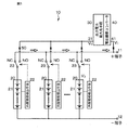
- FIG. 1 is a diagram showing a circuit configuration during normal operation of a battery pack charge / discharge control device according to one preferred embodiment.
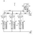
- FIG. 2 is a diagram illustrating a circuit configuration when a certain secondary battery unit is in an internal short-circuit state in a battery pack charge / discharge control device according to a preferred embodiment.
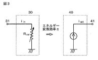
- FIG. 3 is an equivalent circuit diagram of the output power maximizing means and the voltage regulating converter.
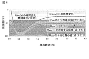
- FIG. 4 is a graph showing a variable range in which the variable resistance value (external resistance value) R var represented by Expression (6), Expression (17), Expression (18), and Expression (19) is not excessive or insufficient.
- 5A and 5B are equivalent circuit diagrams of the secondary battery and the solar battery.
- FIG. 6 is a diagram illustrating a circuit configuration of an assembled battery charge / discharge control device according to another preferred embodiment.
- the present disclosure relates to a charge / discharge control device for an assembled battery. Therefore, the device of the present disclosure includes the assembled battery and the charge / discharge control unit.
- the assembled battery has two or more secondary battery units connected in parallel to each other. Each of the two or more secondary battery units includes one secondary battery, or a plurality of secondary batteries connected directly. That is, a secondary battery unit is composed of one or more secondary batteries, and the secondary battery units are connected in parallel to form an assembled battery.
- the charge / discharge control unit has at least output power maximizing means and a voltage regulating converter.
- the output power maximizing means is means capable of maximizing the power, and in particular, can maximize the output power based on the input power.
- the output power maximizing means preferably functions when a short circuit occurs in the secondary battery unit of the assembled battery.
- the voltage regulating converter is a converter that can convert the output voltage to a desired output voltage, and in particular, can adjust the output voltage from the output power maximizing means. Therefore, the voltage regulating converter preferably functions when a short circuit occurs at least in the secondary battery unit of the assembled battery.
- the output power maximizing means can maximize the output power based on the input power of the secondary battery unit that caused the short circuit.
- the voltage regulating converter can regulate the output voltage from the output power maximizing means to a desired voltage suitable for extraction.
- the assembled battery charge / discharge control device of the present disclosure maximizes the energy of the secondary battery unit of the internal short circuit while reducing the secondary risk caused by the short circuit even when the internal short circuit occurs. It can be said that it can be used effectively.
- the charging reaction of the secondary battery is an endothermic reaction
- “maximized power of the battery unit with internal short circuit” is used for charging the secondary battery unit that is not in the internal short circuit state
- the heat released from the secondary battery unit in the short-circuited state is absorbed by the secondary battery being charged, and the total amount of heat released to the outside from the secondary battery unit in the internal short-circuited state can be further reduced.
- the risk of smoke and ignition of the secondary battery unit that caused the short circuit is further reduced.
- the output unit of the voltage regulating converter may be connected to the output unit of the assembled battery.
- the secondary battery unit that is not in an internal short-circuit state can be charged by the output power from the voltage regulation converter.
- the output voltage (V 1 ) of the voltage regulation converter is used.
- V 1 is equal to (or substantially equal to) the value of V 2
- V 1 > V 2 or V 1 ⁇ V 2 in consideration of the internal impedance of the circuit. obtain.
- the voltage regulating converter is not particularly limited as long as it can perform conversion to a desired voltage.
- the voltage regulating converter may be a boost converter. That is, the converter provided in the assembled battery charge / discharge control device may be capable of making the output side voltage higher than the input side voltage.
- the voltage regulating converter may be a step-down converter. That is, the converter provided in the assembled battery charge / discharge control device may be capable of making the voltage on the output side lower than the voltage on the input side.
- such a voltage regulating converter may be a so-called DC / DC converter.
- the voltage regulation converter may be a step-up / step-down converter that can perform both step-up and step-down.
- the output part of the voltage regulating converter may be connected to the outside of the assembled battery.
- the output power maximization means has a maximum power point tracking (MPPT) control function.
- the output power maximizing means preferably includes a hill-climbing MPPT circuit.
- the MPPT control function or the MPPT circuit itself can be a well-known MPPT control function or MPPT circuit.
- the MPPT is sometimes referred to as “MPPC”.
- the output power maximizing means and the voltage regulating converter are integrated.
- the present invention is not necessarily limited to this, and the output power maximizing means and the voltage regulating converter may be made into separate parts.
- the circuit constituting the voltage regulation converter, itself, can be constituted by a known circuit.
- the secondary battery unit connected to the input unit of the output power maximizing unit and in an internal short-circuit state is disconnected from the assembled battery when a predetermined condition is reached.
- a predetermined condition include a case where the value of the input power to the output power maximizing means of the secondary battery unit in the internal short circuit state is equal to or less than a predetermined value.
- an internal short-circuit detection unit that detects an internal short-circuit state of the secondary battery unit.
- the internal short circuit detecting means is a temperature detecting means, specifically, for example, detecting the temperature of each of the thermistor and thermocouple for detecting the temperature of the secondary battery unit or the secondary battery constituting the secondary battery unit. Thermistors and thermocouples can be used.
- the internal short-circuit detection means can be constituted by voltage measurement means for measuring the voltage of the secondary battery unit or the respective voltages of the secondary batteries constituting the secondary battery unit.
- the internal short circuit detection means may be configured by current measurement means for measuring the current of the secondary battery unit.
- switch means for switching the output destination of the secondary battery unit may be provided. This is particularly true in the case of “a mode in which a plurality of secondary battery units share one voltage regulation converter” described later.
- the switch means may be constituted by an electromagnetic relay or a solid state relay (SSR) which is a relay having no movable contact portion (non-contact relay), but is not limited thereto. For example, it can also be comprised from FET etc.
- the solid-state relay may be a relay composed of semiconductor switching elements such as thyristors, triacs, diodes, and transistors.
- the assembled battery charge / discharge control device of the present disclosure operates both when the secondary battery is charged and when the secondary battery is discharged. Moreover, the assembled battery charge / discharge control device of the present disclosure includes a conventional control device (control circuit) that controls charge / discharge of the secondary battery or the secondary battery unit.
- the type of secondary battery itself is not particularly limited.
- a secondary battery used for the assembled battery charge / discharge control device of the present disclosure for example, a non-aqueous secondary battery, specifically, a lithium ion secondary battery can be given.
- the charging reaction of the lithium ion secondary battery is an endothermic reaction
- the secondary battery unit that is not in the internal short circuit state is charged by the output power from the voltage regulator converter, it is released from the secondary battery unit that is in the internal short circuit state.
- the absorbed heat is absorbed by the secondary battery being charged, and the total amount of heat released to the outside from the secondary battery unit in the internal short circuit state can be further reduced.
- the present invention is not limited to lithium ion secondary batteries.
- a magnesium-air battery a metal-air secondary battery having a negative electrode member containing a negative electrode active material including a metal and an alloy material (used as a negative electrode active material)
- metals and alloy materials include, for example, tin, silicon; alkali metals such as lithium, sodium, and potassium; group 2 elements such as magnesium and calcium; group 13 elements such as aluminum; transition metals such as zinc and iron; Or alloy materials and compounds containing these metals), lithium-sulfur secondary batteries, sodium-sulfur secondary batteries, sodium-nickel chloride secondary batteries, sodium ion secondary batteries, multivalent
- cation secondary batteries various organic secondary batteries, and nickel-hydrogen secondary batteries.
- internal short-circuit related to the assembled battery charge / discharge control device of the present disclosure broadly refers to an event that causes the secondary battery unit to be in an abnormal state that is out of the normal state. Therefore, “internal short circuit” used in the present specification comprehensively includes the meanings of various abnormal states that are normally regarded as abnormal / damaged states in which the secondary battery unit is not in a normal healthy state.
- the charge / discharge control device of the present disclosure can be embodied in various modes.
- a plurality of secondary battery units may share one voltage adjustment converter.
- a plurality of secondary battery units may share one output power maximizing means and one voltage regulating converter.
- FIG. 1 a circuit configuration in which two or more secondary battery units 20 can share a single output power maximizing means 30 and a single voltage regulating converter 40 as shown in FIG. It may be.
- the plurality of secondary battery units may each have a voltage regulation converter corresponding to one-to-one.
- each of the plurality of secondary battery units may individually include output power maximizing means and a voltage regulating converter.
- a plurality of output power maximizing means 30 and a plurality of voltage regulating converters 40 are provided so as to correspond to each of the two or more secondary battery units 20. It may be a circuit configuration.
- FIG. 1 shows a circuit configuration during normal operation of the assembled battery charge / discharge control device of the present disclosure
- FIG. 2 shows a certain secondary battery unit in the assembled battery charge / discharge control device shown in FIG.
- the circuit configuration is shown.
- FIG. 3 shows an equivalent circuit diagram of the output power maximizing means and the voltage regulating converter.
- a plurality of secondary battery units can share the output power maximization means and the voltage regulation converter.
- each secondary battery unit is individually provided with an internal short circuit detection means and a switch means.
- MPPT control for maximizing the power generation amount of a power generation device such as a solar cell or a fuel cell.
- a power generation device such as a solar cell or a fuel cell.
- voltage regulation converters with MPPT control function are commercially available, but such voltage regulation converters are not used to extract energy from solar cells, but are emitted from secondary battery units in an internal short-circuit state.
- the inventor of the present application has eagerly studied that it is possible to efficiently extract the energy released from the secondary battery in an internal short-circuit state to the outside.
- the assembled battery charge / discharge control apparatus 10 shown in FIG. 1 and FIG. 2 includes a secondary battery unit 20 composed of one secondary battery 21 or a secondary battery unit 20 formed by connecting a plurality of secondary batteries 21 in series ( In the illustrated example, the secondary battery unit 20) in which a plurality of secondary batteries 21 are connected in series is the assembled battery charge / discharge control apparatus 10 including two or more assembled batteries connected in parallel. And Output power maximizing means 30 for maximizing output power based on input power, and A voltage adjustment converter 40 that adjusts the output voltage from the output power maximization means 30 is provided.
- each secondary battery unit 20 is Internal short circuit detection means 22 for detecting the internal short circuit state of the secondary battery unit 20, and Switch means 23 for switching the output destination of the secondary battery unit 20, With The switch unit 23 connects the output unit of the secondary battery unit 20 in the internal short circuit state to the input unit 31 of the output power maximizing unit 30 based on the detection result of the internal short circuit detection unit 22.
- the internal short circuit detection means 22 is composed of temperature detection means, specifically, for example, a thermistor that detects the temperature of each of the secondary batteries 21 constituting the secondary battery unit 20. A thermistor that detects the temperature of the secondary battery unit 20 can also be used.
- the internal short-circuit detection unit 22 may include a voltage measurement unit that measures the voltage of the secondary battery unit 20 or the voltage of the secondary battery 21 constituting the secondary battery unit 20.
- the internal short-circuit detection unit 22 may include a current measurement unit that measures the current of the secondary battery unit 20.
- the switch means 23 may be composed of an electromagnetic relay or a solid state relay (SSR).
- the output power maximization means 30 and the voltage regulation converter 40 are integrated, but the present invention is not limited to this, and may be made into individual parts.
- a diode 50 is disposed between the output power maximizing means 30 and the switch means 23, and between the voltage regulating converter 40 and the output unit 11 of the assembled battery, so as to prevent a reverse current flow. Yes.
- the switch means 23 is in the NC (Normally Close) state, and the output of the secondary battery unit 20 is the output unit (+ terminal) 11 and the output unit ( ⁇ terminal) 12 of the assembled battery (assembled battery charge / discharge control device 10). From the state shown in FIG. 1 in normal operation output from the battery, an internal short circuit has occurred in a certain secondary battery unit 20 (more specifically, the secondary battery 21 constituting the secondary battery unit 20) for some reason. Suppose that it occurred. At this time, the internal short-circuit detecting means 22 composed of a thermistor that monitors the temperature of the secondary battery unit 20 (or the temperature of each secondary battery 21) is connected to the temperature (or alternatively each secondary battery unit 20).
- the rise of the temperature of the secondary battery 21) is detected, and under the control of the assembled battery charge / discharge control device 10, the switch means 23 is in a NO (Normally Ooen) state (see FIG. 2). That is, the switch means 23 is based on the detection result of the internal short-circuit detection means 22 (particularly, the detection result of the internal short-circuit detection means 22 provided for each secondary battery unit 20, that is, the detection related to each secondary battery unit 20. Based on the result, the output part of the secondary battery unit 20 in the internal short circuit state is connected to the input part 31 of the output power maximizing means 30. The power of the secondary battery unit 20 in the internal short circuit state flows into the output power maximizing means 30.
- NO Normally Ooen
- the output power maximizing means 30 has a maximum power point tracking (MPPT) control function.
- the output power maximizing means 30 includes a hill-climbing MPPT circuit.
- the output power maximizing means 30 measures the voltage V ′ input to the output power maximizing means 30 and the current i ′ flowing into the output power maximizing means 30.
- the current is i ′ (1)
- the power at that time is P (1)
- the variable resistance value R var of the variable resistor shown in FIG. Let the value be R (1).
- the current is i ′ (2)
- the power at that time is P (2).
- the value R (2) of the variable resistance value R var of the variable resistor provided in the output power maximizing means 30 is R (2) ⁇ R (1) Change (control) so that
- the voltage input to the output power maximization means 30 is adjusted in voltage by the voltage adjustment converter 40 with the energy conversion efficiency ⁇ and output from the output unit 41 of the voltage adjustment converter 40.
- the voltage input to the output power maximizing means 30 is boosted by a voltage adjustment converter 40 provided as a boost converter and output from the output unit 41. In this way, even if the voltage or current value input to the output power maximizing means 30 fluctuates, the power output from the voltage regulating converter 40 can be maximized.
- a part of the released energy of the secondary battery unit 20 in the internal short circuit state (ideally, in the impedance matching state, a maximum of 50% of the released energy of the secondary battery unit 20 in the internal short circuit state) In this way, it is output from the voltage adjustment converter 40.
- the other part of the released energy of the secondary battery unit 20 in the internal short circuit state is converted into heat, but the energy of the secondary battery unit 20 output from the voltage regulating converter 40 is maximized.
- the energy converted into heat in the secondary battery unit 20 in the internal short circuit state can be reduced.
- the output unit 41 of the voltage regulating converter 40 is connected to the output unit 11 of the assembled battery.
- the secondary battery unit 20 that is not in the internal short-circuit state is charged by the output power from the voltage regulating converter 40.
- the output voltage (V 1 ) of the voltage regulating converter 40 is equal to (or substantially equal to) the voltage (V 2 ) of the secondary battery unit 20 not in the internal short circuit state.
- V 1 > V 2 or V 1 ⁇ V 2 in consideration of the impedance of the circuit. In this way, it is possible to effectively use a part of the energy released from the secondary battery unit 20 in the internal short circuit state. A part of the energy released from the secondary battery unit 20 in the internal short circuit state is output to the outside via the output unit 11 of the assembled battery in some cases.
- the secondary battery unit 20 in the internal short circuit state connected to the input unit 31 of the output power maximizing means 30 may be disconnected from the assembled battery when a predetermined condition is reached. Specifically, when the value of the input power to the output power maximizing means 30 of the secondary battery unit in the internal short circuit state becomes equal to or less than a predetermined value, the secondary battery unit is disconnected from the assembled battery. More specifically, for example, if the energy of the secondary battery unit 20 in the internal short circuit state is depleted, the switch means 23 of the secondary battery unit 20 may be left in the NO state, As a third state other than the NC state and the NO state (not shown), the secondary battery unit 20 may be disconnected from the assembled battery.
- the output unit 41 of the voltage regulating converter 40 may be connected to the outside of the assembled battery instead of being connected to the output unit 11 of the assembled battery.
- the resistor in the short-circuit path is a variable resistor and control is performed so that the resistance value is always the optimum value. Even if control cannot always be performed so that the resistance value always becomes the optimum value, at least grasp the minimum and maximum possible resistance values so that the resistance value of the resistor falls within that range. It is necessary to design to.
- the MPPT control Based on the MPPT control, it is possible to maximize the amount of energy drawn from the secondary battery in the internal short circuit state (the amount of generated energy described above). If the operation of the MPPT control is ideal, the heat generation amount is suppressed to 50% at the maximum. This is because the MPPT controlled state and the impedance matching state are electrically equivalent, and the efficiency of energy transfer in the impedance matching state is just 50%. Further, the extracted energy is consumed in the form of charging the secondary battery of the secondary battery unit that is not in the internal short circuit state. That is, when an internal short circuit occurs in a secondary battery in a certain secondary battery unit, the remaining energy of the secondary battery in which the internal short circuit has occurred is quickly and efficiently extracted and extracted. When the energy is consumed in such a manner that a secondary battery constituting another secondary battery unit of the assembled battery is charged, the amount of heat generated when viewed from the whole assembled battery can be suppressed.
- Some commercially available voltage regulation converters with MPPT control function have both short and extremely long time to reach the maximum power point.
- a voltage-regulating converter with an MPPT control function capable of operating as fast as possible.
- the strictest requirement among the performance requirements for the hill-climbing MPPT circuit constituting the output power maximizing means is the input current value.
- variable resistance value (external resistance value) R var of the variable resistor that maximizes the remaining energy in the secondary battery is the internal resistance value R.
- variable resistance value R var (R int ⁇ R short ) / (R int + R short ) (6) (However, when V int ⁇ 0).
- the internal resistance value R int and the short-circuit resistance value R short that change from time to time are obtained. It was used to calculate the variable resistance value R var, the variable resistance value R var, to the computed value obtained sequentially, so that it should be adjusted.
- the internal resistance value R int and the short circuit resistance value R short are not directly obtained values. Therefore, for example, the internal resistance value R int may be estimated from the measured temperature, and the short-circuit resistance value R short may be estimated, for example, by estimating the state of the short circuit (for example, Shinya Sudo, et al. “Refer to Lithium-ion battery nail test (1) -Short-circuit resistance analysis-”, 57th Battery Discussion Meeting, Proceedings of Lecture, 1C19 (2016), Fig. 3) may be applied.
- Equation (6) can be modified as the following equation (provided that R int ⁇ 0).
- R var R short (1 ⁇ R var / R int ) (11)
- Equation (6) since the internal resistance value R int and the short circuit resistance value R short cannot be distinguished from each other, R var ⁇ R short must also be satisfied at the same time.
- the upper limit value of the variable resistance value R var can be determined as follows. R var ⁇ min [R int , R short ] (14)
- the output part of the secondary battery unit in the internal short-circuit state is connected to the input part of the output power maximizing means, and the input power is maximized by the output power.
- the maximum output power is obtained by the means and input to the voltage regulation converter.
- a plurality of secondary battery units can share the output power maximizing means and the voltage regulation converter.
- Each may individually comprise output power maximizing means and a voltage regulating converter. That is, in the assembled battery charge / discharge control device according to the present disclosure, “a plurality of secondary battery units each have a one-to-one voltage regulation converter” may be employed.
- the assembled battery charge / discharge control device includes each secondary battery unit 20.
- Internal short circuit detecting means 22 for detecting the internal short circuit state of the secondary battery unit Have Output power maximizing means 30 and voltage regulating converter 40 are provided for each secondary battery unit 20, respectively.
- the output power maximization means 30 of each secondary battery unit 20 Among them, the output maximizing means 30 of the secondary battery unit 20 in the internal short circuit state is activated.
- FIG. 6 in such a circuit configuration, it is not particularly necessary to separately provide switch means for each secondary battery unit 20.
- the output power maximizing means of the unit that has generated the short circuit when a short circuit occurs in any of the two or more secondary battery units, the output power maximizing means of the unit that has generated the short circuit generates the output power based on the input power of the shorted unit.
- the voltage regulation converter of the unit that has caused the short circuit can regulate the output voltage from the output power maximizing means to a desired voltage.
- the output power maximizing means and the voltage regulating converter of the secondary battery unit that has caused an internal short circuit is the secondary battery in which the short circuit has occurred. It will operate individually to maximize the energy extracted from the unit.
- the output voltage of the voltage regulating converter in the secondary battery unit that has caused the short circuit may be equal (or substantially equal) to the voltage of the secondary battery unit that is not in the internal short circuit state, for example. it can.
- the voltage input to the output power maximization means in the short-circuited secondary battery unit Regardless of fluctuations in the value of the current, the power output from the voltage regulation converters individually provided in the unit is taken out at a desired voltage.
- the above-described “a plurality of secondary battery units share one voltage regulation converter”.
- a part of the released energy of the secondary battery unit 20 in the internal short circuit state (ideally, in the impedance matching state, the maximum of the released energy of the secondary battery unit 20 in the internal short circuit state is 50 %) Is output from the voltage regulating converter 40, and accordingly, the energy converted into heat in the secondary battery unit 20 in the internal short-circuit state can be reduced.
- the power output from the voltage regulating converter 40 of the secondary battery unit 20 in the internal short circuit state is used for charging a healthy secondary battery unit that is not in the internal short circuit state, or is taken out of the assembled battery. It's okay.
- the assembled battery charge / discharge control device of the present disclosure can be suitably used in a UPS (uninterruptible power supply) or the like.
- each secondary battery unit and the voltage adjustment converter provided for each secondary battery unit are: They may be integrated with each other. That is, in the assembled battery charge / discharge control device of the present disclosure, even though a plurality of voltage adjustment converters are provided, the voltage adjustment converters may be integrated with the secondary battery unit and modularized. This can be said to be preferable in terms of versatility for various uses of the present disclosure.
- a server power supply device or the like has a device configuration on the assumption that a secondary battery unit and a voltage regulator converter are integrated. For such applications, the assembled battery according to the present disclosure is used.
- a charge / discharge control device can be suitably used.
- the voltage regulation converter 40 is a boost converter, and the maximum output power from the output power maximization unit 30 is boosted by such a converter.
- the present disclosure is not necessarily limited thereto.
- the voltage regulating converter may be a step-down converter.
- each secondary battery unit may be used with its voltage lowered.
- the voltage regulation converter may have at least the function of a step-down converter.
- the maximum amount taken out from the secondary battery unit in which the short circuit has occurred is stepped down by a step-down converter, and the output part of another healthy secondary battery unit (especially the output of the voltage regulation converter provided in the healthy battery unit)
- the voltage is equal to or substantially equal to the voltage of the component.
- Battery charge / discharge control device An assembled battery charge / discharge control device in which two or more secondary battery units each composed of a single secondary battery or a plurality of secondary batteries connected in series are connected in parallel. There, Output power maximizing means for maximizing output power based on input power; and It has a voltage regulation converter that regulates the output voltage from the output power maximization means, The assembled battery charge / discharge control device in which the output power of the secondary battery unit that caused a short-circuit state among the two or more secondary battery units is maximized.
- Each secondary battery unit is Internal short circuit detection means for detecting the internal short circuit state of the secondary battery unit, and switch means for switching the output destination of the secondary battery unit, The switch unit connects the output unit of the secondary battery unit in the internal short circuit state to the input unit of the output maximizing unit based on the detection result of the internal short circuit detection unit, and the battery pack charge / discharge control device according to [A01] .
- Each secondary battery unit is Having an internal short circuit detecting means for detecting an internal short circuit state of the secondary battery unit; An output power maximizing means and a voltage regulating converter are provided for each secondary battery unit, The assembled battery according to [A01], wherein among the output power maximization means of each secondary battery unit, the output maximization means of the secondary battery unit in the internal short circuit state operates based on the detection result of the internal short circuit detection means.
- Charge / discharge control device [A04] The assembled battery charge / discharge control device according to any one of [A01] to [A03], wherein an output unit of the voltage regulating converter is connected to an output unit of the assembled battery.
- [A05] The assembled battery charge / discharge control device according to any one of [A01] to [A04], wherein the secondary battery unit that is not in the internal short-circuit state is charged by the output power from the voltage regulating converter.
- [A06] The assembled battery charge / discharge control device according to any one of [A01] to [A05], wherein the output voltage of the voltage regulating converter is equal to the voltage of the secondary battery unit not in the internal short circuit state.
- [A07] The assembled battery charge / discharge control device according to any one of [A01] to [A06], wherein an output unit of the voltage regulating converter is connected to the outside of the assembled battery.
- [A08] The assembled battery charge / discharge control device according to any one of [A01] to [A07], wherein the voltage regulating converter is a boost converter.
- [A09] The assembled battery charge / discharge control device according to any one of [A01] to [A07], wherein the voltage regulating converter is a step-down converter.
- [A10] The assembled battery charge / discharge control device according to any one of [A01] to [A09], wherein the output power maximizing means has a maximum power point tracking control function.
- [A11] The assembled battery charge / discharge control device according to any one of [A01] to [A09], wherein the output power maximizing means includes a hill-climbing MPPT circuit.
- [A12] The assembled battery charge / discharge control device according to any one of [A01] to [A11], wherein the output power maximizing means and the voltage regulating converter are integrated.
- [A13] Any of [A01] to [A12], in which the secondary battery unit connected to the input unit of the output power maximizing means and in the internal short-circuit state is disconnected from the assembled battery when a predetermined condition is reached.
- [A14] The assembled battery charge / discharge control device according to any one of [A01] to [A13], wherein the internal short-circuit detection unit includes a temperature detection unit.
- the internal short circuit detection means includes any one of [A01] to [A13], comprising voltage measurement means for measuring the voltage of the secondary battery unit or the voltage of the secondary battery constituting the secondary battery unit.
- [A16] The assembled battery charge / discharge control device according to any one of [A01] to [A13], wherein the internal short-circuit detection means includes current measurement means for measuring a current of the secondary battery unit.
- the switch means includes an electromagnetic relay or a solid state relay.
- Each of the secondary battery units and the voltage adjustment converter provided for each of the secondary battery units are integrated with each other, and any one of [A04] to [A17] subordinate to [A03] Battery pack charge / discharge control device.
- the assembled battery charge / discharge control device of the present disclosure can be used for various applications in which a so-called “assembled battery” is used. Although it is only an example to the last, it can use for a server power supply use etc., or can also be used for uses, such as a drive power supply of moving means represented by a four-wheeled vehicle, a two-wheeled vehicle, a bicycle, an aircraft, etc.
- SYMBOLS 10 Assembly battery charge / discharge control apparatus, 11 ... Output part (+ terminal) of assembled battery (assembled battery charge / discharge control apparatus), 12 ... One terminal of assembled battery (assembled battery charge / discharge control apparatus) , 20 ... secondary battery unit, 21 ... secondary battery, 22 ... internal short circuit detection means, 23 ... switch means, 30 ... output power maximization means, 31 ... output power Input part of maximizing means, 40... Voltage regulating converter, 41... Output part of voltage regulating converter, 50.
Landscapes
- Engineering & Computer Science (AREA)
- Chemical & Material Sciences (AREA)
- Power Engineering (AREA)
- Chemical Kinetics & Catalysis (AREA)
- Electrochemistry (AREA)
- General Chemical & Material Sciences (AREA)
- Manufacturing & Machinery (AREA)
- Materials Engineering (AREA)
- Microelectronics & Electronic Packaging (AREA)
- Secondary Cells (AREA)
- Charge And Discharge Circuits For Batteries Or The Like (AREA)
Abstract
Description
リチウムイオンを吸蔵及び放出する正極活物質を有する正極、
リチウムイオンを吸蔵及び放出する負極、並びに、
正極端子に接続されたダミー正極、及び、負極端子に接続されたダミー負極を交互に積層すると共に、ダミー正極及びダミー負極との間を絶縁する絶縁体を有するダミー積層体、
が設けられ、
ダミー積層体が、交互に積層された正極及び負極の外側に積層されている。
入力電力に基づき出力電力を最大化する出力電力最大化手段、及び
出力電力最大化手段からの出力電圧を調整する電圧調整コンバータ
を有しており、
前記2つ以上の二次電池ユニットのうち短絡状態を引き起こした二次電池ユニットの出力電力が最大化される。
1.本開示の組電池充放電制御装置、全般に関する説明
2.本開示の組電池充放電制御装置のより具体的な好適態様例
3.その他
本開示は、組電池の充放電制御装置に関する。よって、本開示の装置は、組電池を備えるとともに、充放電制御部を備える。組電池は、互いに並列接続された2つ以上の二次電池ユニットを有する。かかる2つ以上の二次電池ユニットの各々は、1つの二次電池から成るものか、あるいは、複数の二次電池が直接接続されて成るものである。つまり、1つ以上の二次電池から二次電池ユニットが構成され、その二次電池ユニットが並列接続されて組電池が構成されている。充放電制御部は、少なくとも出力電力最大化手段および電圧調整コンバータを有している。出力電力最大化手段は、電力を最大にすることができる手段であり、特に入力電力に基づき出力電力を最大にすることができる。それゆえ、出力電力最大化手段は、組電池の二次電池ユニットで短絡が生じた際に好ましくは機能する。電圧調整コンバータは、所望の出力電圧に変換できるコンバータであり、特に出力電力最大化手段からの出力電圧を調整することができる。それゆえ、電圧調整コンバータは、少なくとも組電池の二次電池ユニットで短絡が生じた際に好ましくは機能する。
入力電力に基づき出力電力を最大化する出力電力最大化手段30、及び、
出力電力最大化手段30からの出力電圧を調整する電圧調整コンバータ40、を有している。ここで、各二次電池ユニット20は、
二次電池ユニット20の内部短絡状態を検出する内部短絡検出手段22、及び、
二次電池ユニット20の出力先を切り換えるスイッチ手段23、
を備えており、
スイッチ手段23は、内部短絡検出手段22の検出結果に基づき、内部短絡状態にある二次電池ユニット20の出力部を出力電力最大化手段30の入力部31に接続する。
R(2)<R(1)
となるように変化させる(制御する)。一方、V’(2)<V’(1)、且つ、P(2)<P(1)の場合、又は、V’(2)>V’(1)、且つ、P(2)>P(1)の場合、可変抵抗値Rvarの値R(2)を、
R(2)>R(1)
となるように変化させる(制御する)。P(2)=P(1)の場合、可変抵抗値Rvarの値R(2)は変化させない。
i =(Vvar/Rshort)+(Vvar/Rvar) (1)
Vint={Rint+(Rshort・Rvar)/(Rshort+Rvar)}・i (2)
と表すことができる。式(2)を式(1)に代入して、iを消去し、Vvarについて解く
と、
Vvar=(Rshort・Rvar)Vint/(Rint・Rshort+Rshort・Rvar+Rvar・Rint)
(3)
となる。よって、可変抵抗値Rvarでの発熱(つまり外部に取り出し得るエネルギー)Qvarは、
Qvar=Vvar 2/Rvar
=(Rshort 2・Rvar)Vint 2/(Rint・Rshort+Rshort・Rvar+Rvar・Rint)2
(4)
と書き表される。ここで、Qvarが極値となる可変抵抗値Rvarの条件は、
(∂Qvar)/(∂Rvar)=0 (5)
を満たすときであり、式(4)を可変抵抗値Rvarで微分して可変抵抗値Rvarについて纏めると、
Rvar=(Rint・Rshort)/(Rint+Rshort) (6)
となる(但し、Vint≠0の場合)。
(∂2Qvar)/(∂Rvar 2)
={2Rshort 2(Rint+Rshort)(-2Rint・Rshort+Rshort・Rvar+Rvar・Ri
nt)}・Vint 2/(Rint・Rshort+Rshort・Rvar+Rvar・Rint)4
(7)
-2Rint・Rshort+Rshort・Rvar+Rvar・Rint>0 (8)
が真であるとする。式(8)を変形すると、
Rvar{(Rint+Rshort)/(Rint・Rshort)}-2>0 (9)
となる(但し、Rint≠0、且つ、Rshort≠0の場合)。この式(9)に式(6)を代入すると、
1-2>0 (10)
となり、これは矛盾である。即ち、式(8)は偽りであり、
-2Rint・Rshort+Rshort・Rvar+Rvar・Rint
の値は式(6)が満たされる条件において常に負である。従って、Qvarの2回微分も負であり、Qvarは上に凸であり、よって式(6)の可変抵抗値Rvarは、Qvarの極大点である。
Rvar=Rshort(1-Rvar/Rint) (11)
1-Rvar/Rint>0 (12)
という不等式が成り立つ。ここで、内部抵抗値Rintもまた常に正であることを考慮して式を変形をすると、
Rvar<Rint (13)
という関係が導かれる。即ち、可変抵抗値Rvarは、常に、内部抵抗値Rintよりも小さくなければならないことが判る。尚、式(6)において、内部抵抗値Rintと短絡抵抗値Rshortは互いに区別ができないことから、Rvar<Rshortもまた同時に成り立っていなければならない。こうして、可変抵抗値Rvarの上限値を以下のように決めることができる。
Rvar<min[Rint,Rshort] (14)
Rint/2≦(Rint・Rshort)/(Rint+Rshort)≦Rshort/2 (15)
という関係が成り立ち、また、Rshort≦Rintのときは、式(6)から、
Rshort/2≦(Rint・Rshort)/(Rint+Rshort)≦Rint/2 (16)
という関係が成り立つ。
min[Rint,Rshort]/2≦Rvar<min[Rint,Rshort] (17)
となっているはずであり、且つ、短絡後は温度が単調増加すると仮定して、内部抵抗値Rint(t)が単調減少すると仮定した場合、式(17)における上限値の最大値は、Rint(0)と等しくなる。即ち、
十分な最大値=maxt{min[(Rint(t),Rshort(t)]}=Rint(0)
(18)
である。可変抵抗値Rvarの最小値に関しては、式(17)における下限値の最小値とすれば十分であり、
十分な最小値=mint{min[Rint(t),Rshort(t)]/2}
={min(mint[Rint(t),mintRshort(t)])}/2
(19)
となる。
(A)可変抵抗値Rvarの最大値は、短絡する前の内部抵抗値Rint(0)とすれば十分である。
(B)可変抵抗値Rvarの最小値は、内部抵抗値Rint(t)の最小値と短絡抵抗値Rshort(t)の最小値を個別に考え、その小さい方の値の半分の値とすれば十分である。
となる。この結論を図示したものを図4に示す。
iin(t)=Vin(t)/R(t)
=Vin(t)・{Rint(t)+Rshort(t)}/{Rint(t)・Rshort(t)}
(20)
十分な最大入力電流
=2Vin(t){min[mintRint(t),mintRshort(t)]}
(21)
となる。MPPT制御機能付きの電圧調整コンバータを選定する際には、こうして求められる十分な電流値を考慮すればよい。
二次電池ユニットの内部短絡状態を検出する内部短絡検出手段22
を有し、
出力電力最大化手段30および電圧調整コンバータ40が各二次電池ユニット20に対してそれぞれ設けられており、
内部短絡検出手段22の検出結果(特に、各二次電池ユニット20に対して個々に設けられた内部短絡検出手段22の検出結果)に基づき、各二次電池ユニット20の出力電力最大化手段30のうちで内部短絡状態にある二次電池ユニット20の出力最大化手段30が作動するようになっている。
図6に示す構成から分かるように、このような回路構成では、各二次電池ユニット20に対してスイッチ手段を別途設ける必要は特にない。
[A01]《組電池充放電制御装置》
1つの二次電池から成る二次電池ユニット、又は、複数の二次電池が直列接続されて成る二次電池ユニットが、組電池として2つ以上、並列に接続された組電池充放電制御装置であって、
入力電力に基づき出力電力を最大化する出力電力最大化手段、及び、
出力電力最大化手段からの出力電圧を調整する電圧調整コンバータ
を有しており、
前記2つ以上の二次電池ユニットのうち短絡状態を引き起こした二次電池ユニットの出力電力が最大化される、組電池充放電制御装置。
[A02]各二次電池ユニットが、
二次電池ユニットの内部短絡状態を検出する内部短絡検出手段、および
二次電池ユニットの出力先を切り替えるスイッチ手段
を備えており、
スイッチ手段は、内部短絡検出手段の検出結果に基づき、内部短絡状態にある二次電池ユニットの出力部を出力最大化手段の入力部に接続する、[A01]に記載の組電池充放電制御装置。
[A03]各二次電池ユニットが、
二次電池ユニットの内部短絡状態を検出する内部短絡検出手段
を有し、
出力電力最大化手段および電圧調整コンバータが各二次電池ユニットに対してそれぞれ設けられており、
内部短絡検出手段の検出結果に基づき、各二次電池ユニットの出力電力最大化手段のうちで内部短絡状態にある二次電池ユニットの出力最大化手段が作動する、[A01]に記載の組電池充放電制御装置。
[A04]電圧調整コンバータの出力部は組電池の出力部に接続されている、[A01]~[A03]のいずれかに記載の組電池充放電制御装置。
[A05]電圧調整コンバータからの出力電力によって、内部短絡状態にない二次電池ユニットが充電される、[A01]~[A04]のいずれかに記載の組電池充放電制御装置。
[A06]電圧調整コンバータの出力電圧は、内部短絡状態にない二次電池ユニットの電圧に等しい、[A01]~[A05]のいずれかに記載の組電池充放電制御装置。
[A07]電圧調整コンバータの出力部は組電池の外部に接続されている、[A01]~[A06]のいずれかに記載の組電池充放電制御装置。
[A08]電圧調整コンバータが昇圧コンバータである、[A01]~[A07]のいずれかに記載の組電池充放電制御装置。
[A09]電圧調整コンバータが降圧コンバータである、[A01]~[A07]のいずれかに記載の組電池充放電制御装置。
[A10]出力電力最大化手段は、最大電力点追従制御機能を有する、[A01]~[A09]のいずれかに記載の組電池充放電制御装置。
[A11]出力電力最大化手段は、山登り方式のMPPT回路を備えている、[A01]~[A09]のいずれかに記載の組電池充放電制御装置。
[A12]出力電力最大化手段と電圧調整コンバータとは一体化されている、[A01]~[A11]のいずれかに記載の組電池充放電制御装置。
[A13]出力電力最大化手段の入力部に接続された、内部短絡状態にある二次電池ユニットは、所定の条件に至ったとき、組電池から切り離される、[A01]~[A12]のいずれかに記載の組電池充放電制御装置。
[A14]内部短絡検出手段は、温度検出手段から成る、[A01]~[A13]のいずれかに記載の組電池充放電制御装置。
[A15]内部短絡検出手段は、二次電池ユニットの電圧、又は、二次電池ユニットを構成する二次電池の電圧を測定する電圧測定手段から成る、[A01]~[A13]のいずれかに記載の組電池充放電制御装置。
[A16]内部短絡検出手段は、二次電池ユニットの電流を測定する電流測定手段から成る、[A01]~[A13]のいずれかに記載の組電池充放電制御装置。
[A17]スイッチ手段は、電磁リレー又はソリッド・ステート・リレーから成る、[A01]~[A16]のいずれかに記載の組電池充放電制御装置。
[A18]各二次電池ユニットと、該各二次電池ユニットに対して設けられる電圧調整コンバータとは互いに一体化している、[A03]に従属する[A04]~[A17]のいずれかに記載の組電池充放電制御装置。
Claims (18)
- 1つの二次電池から成る二次電池ユニット、又は、複数の二次電池が直列接続されて成る二次電池ユニットが、組電池として2つ以上、並列に接続された組電池充放電制御装置であって、
入力電力に基づき出力電力を最大化する出力電力最大化手段、及び
出力電力最大化手段からの出力電圧を調整する電圧調整コンバータ
を有しており、
前記2つ以上の二次電池ユニットのうち短絡状態を引き起こした二次電池ユニットの出力電力が最大化される、組電池充放電制御装置。 - 各二次電池ユニットが、
二次電池ユニットの内部短絡状態を検出する内部短絡検出手段、及び
二次電池ユニットの出力先を切り替えるスイッチ手段
を備えており、
スイッチ手段は、内部短絡検出手段の検出結果に基づき、内部短絡状態にある二次電池ユニットの出力部を出力最大化手段の入力部に接続する、請求項1に記載の組電池充放電制御装置。 - 各二次電池ユニットが、
二次電池ユニットの内部短絡状態を検出する内部短絡検出手段
を有し、
出力電力最大化手段および電圧調整コンバータが各二次電池ユニットに対してそれぞれ設けられており、
内部短絡検出手段の検出結果に基づき、各二次電池ユニットの出力電力最大化手段のうちで内部短絡状態にある二次電池ユニットの出力最大化手段が作動する、請求項1に記載の組電池充放電制御装置。 - 電圧調整コンバータの出力部は組電池の出力部に接続されている、請求項1に記載の組電池充放電制御装置。
- 電圧調整コンバータからの出力電力によって、内部短絡状態にない二次電池ユニットが充電される、請求項4に記載の組電池充放電制御装置。
- 電圧調整コンバータの出力電圧は、内部短絡状態にない二次電池ユニットの電圧に等しい、請求項5に記載の組電池充放電制御装置。
- 電圧調整コンバータの出力部は組電池の外部に接続されている、請求項1に記載の組電池充放電制御装置。
- 電圧調整コンバータが昇圧コンバータである、請求項1に記載の組電池充放電制御装置。
- 電圧調整コンバータが降圧コンバータである、請求項1に記載の組電池充放電制御装置。
- 出力電力最大化手段は、最大電力点追従制御機能を有する、請求項1に記載の組電池充放電制御装置。
- 出力電力最大化手段は、山登り方式のMPPT回路を備えている、請求項1に記載の組電池充放電制御装置。
- 出力電力最大化手段と電圧調整コンバータとは一体化されている、請求項1に記載の組電池充放電制御装置。
- 出力電力最大化手段の入力部に接続された、内部短絡状態にある二次電池ユニットは、所定の条件に至ったとき、組電池から切り離される、請求項1に記載の組電池充放電制御装置。
- 内部短絡検出手段は、温度検出手段から成る、請求項1に記載の組電池充放電制御装置。
- 内部短絡検出手段は、二次電池ユニットの電圧、又は、二次電池ユニットを構成する二次電池の電圧を測定する電圧測定手段から成る、請求項1に記載の組電池充放電制御装置。
- 内部短絡検出手段は、二次電池ユニットの電流を測定する電流測定手段から成る、請求項1に記載の組電池充放電制御装置。
- スイッチ手段は、電磁リレー又はソリッド・ステート・リレーから成る、請求項1に記載の組電池充放電制御装置。
- 各二次電池ユニットと、該各二次電池ユニットに対して設けられる電圧調整コンバータとは互いに一体化している、請求項3に記載の組電池充放電制御装置。
Priority Applications (4)
| Application Number | Priority Date | Filing Date | Title |
|---|---|---|---|
| EP18781339.9A EP3609042B1 (en) | 2017-04-07 | 2018-04-06 | Battery pack charge/discharge control device |
| CN201880023184.XA CN110476318B (zh) | 2017-04-07 | 2018-04-06 | 电池组充放电控制装置 |
| JP2019511325A JP6711455B2 (ja) | 2017-04-07 | 2018-04-06 | 組電池充放電制御装置 |
| US16/594,559 US11394060B2 (en) | 2017-04-07 | 2019-10-07 | Battery pack charge/discharge control device that suppress heat generation when internal short circuit occurs in a secondary battery |
Applications Claiming Priority (2)
| Application Number | Priority Date | Filing Date | Title |
|---|---|---|---|
| JP2017076959 | 2017-04-07 | ||
| JP2017-076959 | 2017-04-07 |
Related Child Applications (1)
| Application Number | Title | Priority Date | Filing Date |
|---|---|---|---|
| US16/594,559 Continuation US11394060B2 (en) | 2017-04-07 | 2019-10-07 | Battery pack charge/discharge control device that suppress heat generation when internal short circuit occurs in a secondary battery |
Publications (1)
| Publication Number | Publication Date |
|---|---|
| WO2018186496A1 true WO2018186496A1 (ja) | 2018-10-11 |
Family
ID=63712628
Family Applications (1)
| Application Number | Title | Priority Date | Filing Date |
|---|---|---|---|
| PCT/JP2018/014783 Ceased WO2018186496A1 (ja) | 2017-04-07 | 2018-04-06 | 組電池充放電制御装置 |
Country Status (5)
| Country | Link |
|---|---|
| US (1) | US11394060B2 (ja) |
| EP (1) | EP3609042B1 (ja) |
| JP (1) | JP6711455B2 (ja) |
| CN (1) | CN110476318B (ja) |
| WO (1) | WO2018186496A1 (ja) |
Cited By (3)
| Publication number | Priority date | Publication date | Assignee | Title |
|---|---|---|---|---|
| CN112687997A (zh) * | 2019-10-18 | 2021-04-20 | 株式会社Lg化学 | 电池组和包括该电池组的车辆 |
| WO2021235738A1 (ko) * | 2020-05-22 | 2021-11-25 | 주식회사 엘지에너지솔루션 | 배터리 팩, 및 그것을 포함하는 배터리 랙, 및 전력 저장 장치 |
| WO2025089078A1 (ja) * | 2023-10-27 | 2025-05-01 | オムロン株式会社 | 蓄電装置、蓄電システム、制御方法及びプログラム |
Families Citing this family (4)
| Publication number | Priority date | Publication date | Assignee | Title |
|---|---|---|---|---|
| CN110838742A (zh) * | 2019-10-25 | 2020-02-25 | 深圳市道通智能航空技术有限公司 | 充电装置、充电系统和充电方法 |
| JP7191873B2 (ja) * | 2020-01-17 | 2022-12-19 | 株式会社東芝 | 充放電制御装置、充放電システム、充放電制御方法及び充放電制御プログラム |
| JP2024531098A (ja) | 2021-08-12 | 2024-08-29 | ミルウォーキー エレクトリック ツール コーポレイション | 電動工具バッテリパックのための電力供給調整器 |
| JP7705308B2 (ja) * | 2021-08-31 | 2025-07-09 | 株式会社Subaru | 車両 |
Citations (4)
| Publication number | Priority date | Publication date | Assignee | Title |
|---|---|---|---|---|
| JPH11191436A (ja) * | 1997-12-26 | 1999-07-13 | Hitachi Ltd | 蓄電保護器 |
| JP2009087600A (ja) | 2007-09-28 | 2009-04-23 | Mitsubishi Heavy Ind Ltd | リチウム二次電池 |
| JP2010231939A (ja) * | 2009-03-26 | 2010-10-14 | Ntt Facilities Inc | 予備電源システム及び予備電源システム保護方法 |
| JP2017076959A (ja) | 2001-05-29 | 2017-04-20 | 株式会社半導体エネルギー研究所 | 半導体装置 |
Family Cites Families (13)
| Publication number | Priority date | Publication date | Assignee | Title |
|---|---|---|---|---|
| US4272806A (en) * | 1979-06-08 | 1981-06-09 | Eastman Kodak Company | DC to DC Converter adjustable dynamically to battery condition |
| US9130401B2 (en) * | 2006-12-06 | 2015-09-08 | Solaredge Technologies Ltd. | Distributed power harvesting systems using DC power sources |
| JP5815195B2 (ja) * | 2008-09-11 | 2015-11-17 | ミツミ電機株式会社 | 電池状態検知装置及びそれを内蔵する電池パック |
| JP5439800B2 (ja) * | 2008-12-04 | 2014-03-12 | ミツミ電機株式会社 | 二次電池保護用集積回路装置及びこれを用いた二次電池保護モジュール並びに電池パック |
| US8716980B2 (en) * | 2009-02-04 | 2014-05-06 | Samsung Sdi Co., Ltd. | Charge and discharge system of secondary battery and method of controlling charge and discharge of secondary battery |
| JP5289083B2 (ja) * | 2009-02-05 | 2013-09-11 | 三洋電機株式会社 | 二次電池の異常検出装置および二次電池装置 |
| WO2010138948A2 (en) * | 2009-05-28 | 2010-12-02 | Deeya Energy, Inc. | Buck-boost control circuit |
| JP2012039821A (ja) * | 2010-08-10 | 2012-02-23 | Toshiba Corp | 発電システムの電力変動緩和装置および電力変動緩和方法 |
| JP5920469B2 (ja) * | 2012-08-14 | 2016-05-18 | 日産自動車株式会社 | 電源装置 |
| DE102014102352A1 (de) * | 2014-02-24 | 2015-08-27 | Ge Energy Power Conversion Technology Limited | Batteriespeichersystem mit Störlichtbogenschutz, Energieumwandlungssystem und Schutzverfahren |
| JP6821584B2 (ja) * | 2015-10-30 | 2021-01-27 | 三洋電機株式会社 | 蓄電システム |
| JP5980457B1 (ja) * | 2016-03-30 | 2016-08-31 | 本田技研工業株式会社 | 電源装置、該電源装置を有する輸送機器、蓄電部の充電率と開放端電圧の相関情報を推定する推定方法、および該相関情報を推定するためのプログラム |
| US11063306B2 (en) * | 2017-06-11 | 2021-07-13 | Lenovo (Singapore) Pte. Ltd. | Lithium-ion battery cut-off voltage adjustment |
-
2018
- 2018-04-06 JP JP2019511325A patent/JP6711455B2/ja active Active
- 2018-04-06 EP EP18781339.9A patent/EP3609042B1/en active Active
- 2018-04-06 WO PCT/JP2018/014783 patent/WO2018186496A1/ja not_active Ceased
- 2018-04-06 CN CN201880023184.XA patent/CN110476318B/zh active Active
-
2019
- 2019-10-07 US US16/594,559 patent/US11394060B2/en active Active
Patent Citations (4)
| Publication number | Priority date | Publication date | Assignee | Title |
|---|---|---|---|---|
| JPH11191436A (ja) * | 1997-12-26 | 1999-07-13 | Hitachi Ltd | 蓄電保護器 |
| JP2017076959A (ja) | 2001-05-29 | 2017-04-20 | 株式会社半導体エネルギー研究所 | 半導体装置 |
| JP2009087600A (ja) | 2007-09-28 | 2009-04-23 | Mitsubishi Heavy Ind Ltd | リチウム二次電池 |
| JP2010231939A (ja) * | 2009-03-26 | 2010-10-14 | Ntt Facilities Inc | 予備電源システム及び予備電源システム保護方法 |
Non-Patent Citations (1)
| Title |
|---|
| See also references of EP3609042A4 |
Cited By (7)
| Publication number | Priority date | Publication date | Assignee | Title |
|---|---|---|---|---|
| CN112687997A (zh) * | 2019-10-18 | 2021-04-20 | 株式会社Lg化学 | 电池组和包括该电池组的车辆 |
| WO2021075743A1 (ko) * | 2019-10-18 | 2021-04-22 | 주식회사 엘지화학 | 배터리 팩 및 이러한 배터리 팩을 포함하는 자동차 |
| KR20210046404A (ko) * | 2019-10-18 | 2021-04-28 | 주식회사 엘지화학 | 배터리 팩 및 이러한 배터리 팩을 포함하는 자동차 |
| KR102792385B1 (ko) * | 2019-10-18 | 2025-04-04 | 주식회사 엘지에너지솔루션 | 배터리 팩 및 이러한 배터리 팩을 포함하는 자동차 |
| WO2021235738A1 (ko) * | 2020-05-22 | 2021-11-25 | 주식회사 엘지에너지솔루션 | 배터리 팩, 및 그것을 포함하는 배터리 랙, 및 전력 저장 장치 |
| US12412937B2 (en) | 2020-05-22 | 2025-09-09 | Lg Energy Solution, Ltd. | Battery pack, battery rack comprising the same and energy storage system |
| WO2025089078A1 (ja) * | 2023-10-27 | 2025-05-01 | オムロン株式会社 | 蓄電装置、蓄電システム、制御方法及びプログラム |
Also Published As
| Publication number | Publication date |
|---|---|
| JPWO2018186496A1 (ja) | 2019-11-21 |
| US20200036050A1 (en) | 2020-01-30 |
| EP3609042B1 (en) | 2026-03-25 |
| EP3609042A1 (en) | 2020-02-12 |
| CN110476318B (zh) | 2024-05-03 |
| US11394060B2 (en) | 2022-07-19 |
| CN110476318A (zh) | 2019-11-19 |
| EP3609042A4 (en) | 2021-01-06 |
| JP6711455B2 (ja) | 2020-06-17 |
Similar Documents
| Publication | Publication Date | Title |
|---|---|---|
| JP6711455B2 (ja) | 組電池充放電制御装置 | |
| JP6818156B2 (ja) | バッテリパック、及びバッテリパックの充電制御方法 | |
| US8217628B2 (en) | Battery pack with an automatic current regulation and charging method for the same | |
| US12424681B2 (en) | Battery pack | |
| KR101074785B1 (ko) | 배터리 관리 시스템 및 이의 제어 방법, 및 배터리 관리 시스템을 포함한 에너지 저장 시스템 | |
| US20140176043A1 (en) | Charging control unit | |
| US20190386352A1 (en) | Battery pack temperature control method and device | |
| CN101192757A (zh) | 充电系统、充电装置以及电池组件 | |
| JP5509655B2 (ja) | 燃料電池システム及びこれを備えた車両 | |
| CN1312821C (zh) | 电池组的充电率调整电路 | |
| JP2010238530A (ja) | 燃料電池システム及びこれを備えた車両 | |
| KR20140125178A (ko) | 외장 배터리 | |
| WO2012050195A1 (ja) | 電力供給システム | |
| WO2012050180A1 (ja) | 優先回路及び電力供給システム | |
| US9196933B2 (en) | System and method for discharging a high impedance battery | |
| WO2019187692A1 (ja) | 電池パック及びその充電制御方法 | |
| JP6648539B2 (ja) | 電力貯蔵システム | |
| Mastanamma et al. | EV BMS with charge monitor and fire detection | |
| KR20240028849A (ko) | 배터리 관리 장치 및 그것의 동작 방법 | |
| JP2009071922A (ja) | 直流バックアップ電源装置およびその制御方法 | |
| JP2008131710A (ja) | 電源システム、電源システムの制御方法、電源システムの制御方法を実行するためのプログラムおよび電源システムの制御方法を実行するためのプログラムを記録した記録媒体 | |
| KR20210050441A (ko) | 전력 공급 시스템 및 이를 포함하는 차량 | |
| JP2018129896A (ja) | 電池管理ユニット | |
| JP2009124934A (ja) | 電源装置 | |
| TW201445851A (zh) | 雙向電流調節裝置及其調節方法 |
Legal Events
| Date | Code | Title | Description |
|---|---|---|---|
| 121 | Ep: the epo has been informed by wipo that ep was designated in this application |
Ref document number: 18781339 Country of ref document: EP Kind code of ref document: A1 |
|
| ENP | Entry into the national phase |
Ref document number: 2019511325 Country of ref document: JP Kind code of ref document: A |
|
| NENP | Non-entry into the national phase |
Ref country code: DE |
|
| WWE | Wipo information: entry into national phase |
Ref document number: 2018781339 Country of ref document: EP |
|
| ENP | Entry into the national phase |
Ref document number: 2018781339 Country of ref document: EP Effective date: 20191107 |
|
| WWG | Wipo information: grant in national office |
Ref document number: 2018781339 Country of ref document: EP |