WO2018189790A1 - 空調換気装置、空気調和システム、および、制御方法 - Google Patents
空調換気装置、空気調和システム、および、制御方法 Download PDFInfo
- Publication number
- WO2018189790A1 WO2018189790A1 PCT/JP2017/014708 JP2017014708W WO2018189790A1 WO 2018189790 A1 WO2018189790 A1 WO 2018189790A1 JP 2017014708 W JP2017014708 W JP 2017014708W WO 2018189790 A1 WO2018189790 A1 WO 2018189790A1
- Authority
- WO
- WIPO (PCT)
- Prior art keywords
- air
- passage
- outdoor
- cooling
- bypass
- Prior art date
- Legal status (The legal status is an assumption and is not a legal conclusion. Google has not performed a legal analysis and makes no representation as to the accuracy of the status listed.)
- Ceased
Links
Images


Classifications
-
- F—MECHANICAL ENGINEERING; LIGHTING; HEATING; WEAPONS; BLASTING
- F24—HEATING; RANGES; VENTILATING
- F24F—AIR-CONDITIONING; AIR-HUMIDIFICATION; VENTILATION; USE OF AIR CURRENTS FOR SCREENING
- F24F11/00—Control or safety arrangements
- F24F11/0001—Control or safety arrangements for ventilation
-
- F—MECHANICAL ENGINEERING; LIGHTING; HEATING; WEAPONS; BLASTING
- F24—HEATING; RANGES; VENTILATING
- F24F—AIR-CONDITIONING; AIR-HUMIDIFICATION; VENTILATION; USE OF AIR CURRENTS FOR SCREENING
- F24F12/00—Use of energy recovery systems in air conditioning, ventilation or screening
- F24F12/001—Use of energy recovery systems in air conditioning, ventilation or screening with heat-exchange between supplied and exhausted air
- F24F12/006—Use of energy recovery systems in air conditioning, ventilation or screening with heat-exchange between supplied and exhausted air using an air-to-air heat exchanger
-
- F—MECHANICAL ENGINEERING; LIGHTING; HEATING; WEAPONS; BLASTING
- F24—HEATING; RANGES; VENTILATING
- F24F—AIR-CONDITIONING; AIR-HUMIDIFICATION; VENTILATION; USE OF AIR CURRENTS FOR SCREENING
- F24F11/00—Control or safety arrangements
- F24F11/70—Control systems characterised by their outputs; Constructional details thereof
- F24F11/80—Control systems characterised by their outputs; Constructional details thereof for controlling the temperature of the supplied air
- F24F11/81—Control systems characterised by their outputs; Constructional details thereof for controlling the temperature of the supplied air by controlling the air supply to heat-exchangers or bypass channels
-
- F—MECHANICAL ENGINEERING; LIGHTING; HEATING; WEAPONS; BLASTING
- F24—HEATING; RANGES; VENTILATING
- F24F—AIR-CONDITIONING; AIR-HUMIDIFICATION; VENTILATION; USE OF AIR CURRENTS FOR SCREENING
- F24F7/00—Ventilation
- F24F7/04—Ventilation with ducting systems, e.g. by double walls; with natural circulation
- F24F7/06—Ventilation with ducting systems, e.g. by double walls; with natural circulation with forced air circulation, e.g. by fan positioning of a ventilator in or against a conduit
- F24F7/10—Ventilation with ducting systems, e.g. by double walls; with natural circulation with forced air circulation, e.g. by fan positioning of a ventilator in or against a conduit with air supply, or exhaust, through perforated wall, floor or ceiling
-
- F—MECHANICAL ENGINEERING; LIGHTING; HEATING; WEAPONS; BLASTING
- F24—HEATING; RANGES; VENTILATING
- F24F—AIR-CONDITIONING; AIR-HUMIDIFICATION; VENTILATION; USE OF AIR CURRENTS FOR SCREENING
- F24F11/00—Control or safety arrangements
- F24F11/30—Control or safety arrangements for purposes related to the operation of the system, e.g. for safety or monitoring
- F24F11/46—Improving electric energy efficiency or saving
-
- F—MECHANICAL ENGINEERING; LIGHTING; HEATING; WEAPONS; BLASTING
- F24—HEATING; RANGES; VENTILATING
- F24F—AIR-CONDITIONING; AIR-HUMIDIFICATION; VENTILATION; USE OF AIR CURRENTS FOR SCREENING
- F24F12/00—Use of energy recovery systems in air conditioning, ventilation or screening
- F24F12/001—Use of energy recovery systems in air conditioning, ventilation or screening with heat-exchange between supplied and exhausted air
- F24F2012/007—Use of energy recovery systems in air conditioning, ventilation or screening with heat-exchange between supplied and exhausted air using a by-pass for bypassing the heat-exchanger
-
- Y—GENERAL TAGGING OF NEW TECHNOLOGICAL DEVELOPMENTS; GENERAL TAGGING OF CROSS-SECTIONAL TECHNOLOGIES SPANNING OVER SEVERAL SECTIONS OF THE IPC; TECHNICAL SUBJECTS COVERED BY FORMER USPC CROSS-REFERENCE ART COLLECTIONS [XRACs] AND DIGESTS
- Y02—TECHNOLOGIES OR APPLICATIONS FOR MITIGATION OR ADAPTATION AGAINST CLIMATE CHANGE
- Y02B—CLIMATE CHANGE MITIGATION TECHNOLOGIES RELATED TO BUILDINGS, e.g. HOUSING, HOUSE APPLIANCES OR RELATED END-USER APPLICATIONS
- Y02B30/00—Energy efficient heating, ventilation or air conditioning [HVAC]
- Y02B30/56—Heat recovery units
Definitions
- the present invention relates to an air-conditioning ventilator, an air conditioning system, and a control method that can appropriately improve energy saving during outdoor air cooling.
- this air-conditioning system includes a ventilator equipped with a heat exchanger (total heat exchanger or sensible heat exchanger), and is used to replace indoor air with outdoor air (fresh air).
- the generated air conditioning load can be reduced. For example, in the summer season, if high-temperature outdoor air is taken in as it is, the indoor temperature will rise greatly. However, by exchanging heat with the indoor air using the heat exchanger of the ventilator, the cooled outdoor air is transferred into the room. Supplied. For this reason, the rise in room temperature is suppressed and the air conditioning load is reduced.
- Patent Document 1 An invention of an air conditioning system provided with such a ventilator is disclosed in Patent Document 1, for example.
- the heat exchanger is bypassed, and the low-temperature outdoor air is taken into the room as it is, so that the outdoor air cooling effect is obtained. can get.
- the air conditioning load of the air conditioning system is reduced to improve energy saving.
- Patent Document 1 it is necessary to increase the ventilation air volume to some extent in order to enhance the outside air cooling effect.
- the amount of power consumption is increased by increasing the air flow rate of the fan in the ventilator. For this reason, even if it considers the part which reduced the air-conditioning load, it was not so effective for the improvement of energy saving property.
- the present invention has been made in order to solve the above-described problems, and an object thereof is to appropriately improve the energy saving property at the time of outdoor air cooling.
- an air-conditioning ventilator comprises: A first air passage for arranging the first air blowing means and supplying outdoor air into the room; A second air passage for disposing indoor air to the outside, wherein second air blowing means is disposed; Heat exchange means for performing heat exchange between air passing through the first air passage and air passing through the second air passage; A bypass air passage formed by being joined to one of the first and second air passages, and bypassing the heat exchange means; Air path switching means for opening and closing the bypass air path and switching the air path of the passing air; The first and second air blowing means, and a control means for controlling the air path switching means, The control means controls the air path switching means to open the bypass air path at the time of outside air cooling for taking outdoor air into the room, and is disposed in the air path in which the bypass air path is not formed. The blown means is stopped.
- the control means controls the air path switching means to open the bypass air path, and stops the air blowing means arranged in the air path where the bypass air path is not formed.
- Schematic diagram for explaining the external configuration of the air-conditioning ventilator Schematic diagram for explaining the connection configuration of the air-conditioning ventilator Schematic diagram for explaining the flow of room air during outdoor air cooling
- Schematic diagram for explaining the flow of outdoor air during outdoor air cooling Flow chart showing an example of outside air cooling control processing
- Schematic diagram for explaining the connection configuration of the air-conditioning ventilator Flow chart showing an example of outside air cooling control processing The schematic diagram which shows an example of the whole structure of the air conditioning system which concerns on Embodiment 3 of this invention.
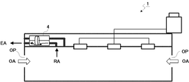
- FIG. 1 is a schematic diagram illustrating an example of the overall configuration of an air-conditioning system 1 according to Embodiment 1 of the present invention.
- the air conditioning system 1 is installed, for example, in a building represented by a building, and includes an air-conditioning ventilator 4, an outdoor unit 5, and a plurality of indoor units 6, as shown in the figure.
- the outdoor unit 5 and the plurality of indoor units 6 are connected through a pipe P.
- the number of the outdoor units 5 and the indoor units 6 is an example, and can be appropriately changed according to the floor area of a building (floor), for example.
- the air-conditioning ventilator 4 is installed, for example, on the ceiling of a building, and exchanges indoor air and outdoor air. That is, the air-conditioning ventilator 4 supplies the outdoor air OA to the room as the supply air SA and discharges the room air RA to the outside as the discharge air EA.
- the external configuration of the air-conditioning ventilator 4 will be described with reference to FIG.
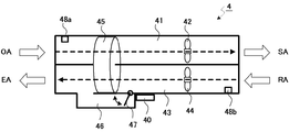
- FIG. 2 is a schematic diagram for explaining the external configuration of the air-conditioning ventilator 4.
- the air-conditioning ventilator 4 includes a control unit 40 as control means, an air supply air path 41 as a first air path, an air supply fan 42 as first air blowing means, and a second air flow.
- An exhaust air passage 43 as a passage, an exhaust fan 44 as a second air blowing means, a total heat exchanger 45 as a heat exchange means, a bypass air passage 46, a damper 47 as an air passage switching means, and a sensor 48 (48a, 48b).
- the control unit 40 controls the entire air conditioning ventilator 4. Details of the control unit 40 will be described with reference to FIG.
- the air supply air passage 41 is an air passage for supplying the outdoor air OA into the room as the supply air SA, and an air supply fan 42 is disposed.
- the air supply fan 42 is driven (rotated) under the control of the control unit 40 and takes the outdoor air OA into the air supply air passage 41.
- the exhaust air path 43 is an air path for exhausting the room air RA to the outside as the exhaust air EA, and an exhaust fan 44 is disposed.
- the exhaust fan 44 is driven under the control of the control unit 40 and takes in the room air RA into the exhaust air passage 43.
- the total heat exchanger 45 performs total heat exchange between the outdoor air OA that passes through the supply air passage 41 and the indoor air RA that passes through the exhaust air passage 43.
- the outdoor air OA after the total heat exchange is supplied indoors as the supply air SA, while the indoor air RA after the total heat exchange is discharged outside as the exhaust air EA.
- a sensible heat exchanger may be used instead of the total heat exchanger 45.
- the bypass air passage 46 is formed so as to be joined to the exhaust air passage 43, and the indoor air RA passing through the exhaust air passage 43 is used as an air passage for bypassing without passing through the total heat exchanger 45. it can.
- the bypass air passage 46 has a lower air passage resistance when passing through the bypass air passage 46 than the air passage resistance when passing through the total heat exchanger 45 (for example, a resistance of 1/2). It is formed to become.
- a damper 47 is disposed at one joint portion (by way of example, a joint portion on the indoor side) between the bypass air passage 46 and the exhaust air passage 43.
- the damper 47 is opened and closed under the control of the control unit 40 and switches the air path of the room air RA passing through the exhaust air path 43. That is, when the damper 47 is closed, the room air RA passes through the total heat exchanger 45. On the other hand, when the damper 47 is opened, the room air RA passes through the bypass air passage 46 (that is, bypasses without passing through the total heat exchanger 45).
- bypass air passage 46 is formed to be joined to the exhaust air passage 43 in the embodiment of the present invention (Embodiments 1 to 3), the case where the bypass air passage 46 is formed to be joined to the exhaust air passage 43 is described as an example, but on the contrary, The bypass air passage 46 may be formed so as to be joined to the air supply air passage 41. In that case, the bypass air passage 46 is used as an air passage for the outdoor air OA passing through the supply air passage 41 to bypass without passing through the total heat exchanger 45.
- Sensor 48 is, for example, a temperature / humidity sensor, and is arranged in supply air passage 41 (in the vicinity of the outdoor side as an example) and exhaust air passage 43 (in the vicinity of the indoor side as an example).
- the sensor 48 a detects the temperature and humidity of the outdoor air OA passing through the supply air passage 41 and supplies the data (detection result) to the control unit 40.
- the sensor 48 b detects the temperature and humidity of the room air RA passing through the exhaust air passage 43 and supplies the data to the controller 40.
- the sensor 48 may be a temperature sensor that detects only the temperature.
- FIG. 3 is a block diagram for explaining the connection configuration of the air-conditioning ventilator 4.
- the control unit 40 includes a determination unit 401 as a determination unit, a command unit 402, and a storage unit 403.
- the control unit 40 includes, for example, a CPU (Central Processing Unit), a ROM (Read Only Memory), a RAM (Random Access Memory), and the like.
- the determination unit 401 and the command unit 402 are realized, for example, when the CPU uses the RAM as a work memory and appropriately executes various programs stored in the ROM.
- the determination unit 401 determines the validity / invalidity of the outdoor air cooling that takes the outdoor air OA into the room based on the detection result of the sensor 48. For example, the determination unit 401 compares the outdoor air enthalpy obtained from the temperature and humidity of the outdoor air OA detected by the sensor 48a and the indoor air enthalpy obtained from the temperature and humidity of the indoor air RA detected by the sensor 48b. When the outdoor air enthalpy is lower than the indoor air enthalpy, the determination unit 401 determines that the outdoor air cooling is effective. On the other hand, in the opposite case, the determination unit 401 determines that the outside air cooling is invalid.
- the determination unit 401 determines whether the indoor unit 6 is in cooling operation (whether a cooling load is generated). Including, the effectiveness of the outside air cooling is determined. That is, the determination unit 401 determines that the outdoor air cooling is effective only when the outdoor air enthalpy is lower than the indoor air enthalpy and a cooling load is generated.
- the command unit 402 sends necessary commands to, for example, an actuator that drives the damper 47, a motor driver that rotates the air supply fan 42, and a motor driver that rotates the exhaust fan 44.
- the command unit 402 sends a command for performing the outside air cooling. That is, the command unit 402 sends an open command to the actuator of the damper 47 to open the damper 47 and sends a stop command to the motor driver of the air supply fan 42 to stop the air supply fan 42. Further, the command unit 402 may increase the air volume of the exhaust fan 44 by sending a strong rotation command to the motor driver of the exhaust fan 44.
- the outdoor air OA flows into the room through an opening OP represented by a window or a door. That is, when the air-conditioning ventilator 4 discharges the indoor air RA as the discharged air EA to the outside, the outdoor air OA flows into the room through the opening OP.
- the storage unit 403 stores various information necessary for controlling the air-conditioning ventilator 4.
- the storage unit 403 stores a program for executing an outside air cooling control process described later.
- the outdoor unit 5 has, for example, a compressor and a heat source side heat exchanger, and is connected to the indoor unit 6 by a pipe P.
- the outdoor unit 5 circulates the refrigerant with the indoor unit 6 through the pipe P.
- the outdoor unit 5 is installed outdoors (for example, on the roof of a building).
- the indoor unit 6 has, for example, an expansion valve and a load side heat exchanger, and is connected to the outdoor unit 5 by a pipe P. And the indoor unit 6 air-conditions a room
- the indoor unit 6 is embedded in a ceiling plate of a building (floor).
- FIG. 6 is a flowchart illustrating an example of the outside air cooling control process executed by the air conditioning ventilator 4 (control unit 40). This outside air cooling control process is repeatedly executed, for example, every time a predetermined time elapses.
- the control unit 40 acquires outdoor and indoor temperature and humidity (step S101). That is, the control unit 40 acquires the temperature and humidity of the outdoor air OA from the sensor 48a, and acquires the temperature and humidity of the indoor air RA from the sensor 48b.
- the control unit 40 determines whether or not the outside air cooling is effective (step S102). That is, the determination unit 401 determines the validity / invalidity of the outside air cooling based on the temperature / humidity acquired in step S101. For example, the determination unit 401 compares the outdoor air enthalpy obtained from the temperature and humidity of the outdoor air OA and the indoor air enthalpy obtained from the temperature and humidity of the indoor air RA. When the outdoor air enthalpy is lower than the indoor air enthalpy, the determination unit 401 determines that the outdoor air cooling is effective. On the other hand, in the opposite case, the determination unit 401 determines that the outside air cooling is invalid.
- the determination unit 401 when the operation status of the indoor unit 6 is obtained, the determination unit 401 includes the outdoor air cooling including whether the indoor unit 6 is performing a cooling operation (whether a cooling load is generated). Valid / invalid is determined. That is, the determination unit 401 determines that the outdoor air cooling is effective only when the outdoor air enthalpy is lower than the indoor air enthalpy and a cooling load is generated.
- the control unit 40 opens the damper 47 and stops the air supply fan 42 (step S103). That is, the command unit 402 sends an open command to the actuator that drives the damper 47 to open the damper 47 and sends a stop command to the motor driver that rotates the air supply fan 42 to stop the air supply fan 42. Further, the command unit 402 may increase the air volume of the exhaust fan 44 by sending a strong rotation command to a motor driver that rotates the exhaust fan 44.
- control unit 40 skips the process of step S103 and performs the outside air cooling control process. Finish.
- the outdoor air OA flows into the room through the opening OP as shown in FIG. That is, when the air-conditioning ventilator 4 discharges the indoor air RA as the discharged air EA to the outside, the outdoor air OA flows into the room through the opening OP.
- step S104 the control unit 40 closes the damper 47 and drives the air supply fan 42 ( (Step S104). That is, the command unit 402 sends a close command to the actuator that drives the damper 47 to close the damper 47 and sends a rotation command to the motor driver that rotates the air supply fan 42 to stop the supply fan 42 that has been stopped. Drive. Further, when the air volume of the exhaust fan 44 is increased, the command unit 402 sends a rotation return command to the motor driver that rotates the exhaust fan 44 to return the air volume of the exhaust fan 44.
- control unit 40 If the outside air is not being cooled (if the damper 47 has been closed and the supply fan 42 has been driven), the control unit 40 skips the process of step S104 and ends the outside air cooling control process. .
- the air supply fan 42 (that is, the air blowing means arranged in the air passage where the bypass air passage 46 is not formed) is stopped, so that the fan power can be reduced.
- the ventilation air volume of the exhaust fan 44 that is, the air blowing unit disposed in the air passage where the bypass air passage 46 is formed
- the blower power of the entire air-conditioning ventilator 4 does not increase compared to that before the outside air cooling. As a result, it is possible to appropriately improve the energy saving performance during the outdoor air cooling.
- Embodiment 2 In the first embodiment, the case where the opening OP as shown in FIG. 5 can be used has been described. However, when all windows, doors, and the like are closed, such an opening OP cannot be used. Therefore, you may enable it to perform opening / closing control of a window, a door, etc. on the system side.
- Embodiment 2 of the present invention will be described.
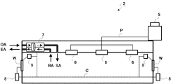
- FIG. 7 is a schematic diagram showing an example of the overall configuration of the air-conditioning system 2 according to Embodiment 2 of the present invention.
- the air conditioning system 2 includes an air conditioning ventilator 7, an outdoor unit 5, a plurality of indoor units 6, a plurality of opening / closing mechanisms 8, and a plurality of opening / closing sensors 9.
- the outdoor unit 5 and the indoor unit 6 are the same as the air conditioning system 1 of FIG.
- the air-conditioning ventilator 7, the opening / closing mechanism 8, and the opening / closing sensor 9 are connected via a communication line C so as to communicate with each other.
- the numbers of the opening / closing mechanisms 8 and the opening / closing sensors 9 are examples, and can be changed as appropriate.
- the opening / closing mechanism 8 as an opening / closing means is controlled by the air-conditioning ventilator 7 through the communication line C, and opens and closes a door portion W (for example, a window, a door, etc.) provided in the building.
- the opening / closing mechanism 8 can open and close the door W even in response to a manual operation by the user.
- the open / close sensor 9 detects the open / closed state of the door W and notifies the air conditioning ventilator 7 via the communication line C.
- FIG. 8 is a block diagram for explaining the connection configuration of the air-conditioning ventilator 7.
- the external appearance structure of the air-conditioning ventilator 7 is the same as that of the air-conditioning ventilator 4 of FIG. 3 mentioned above.
- the control unit 70 includes a determination unit 401, a command unit 702, and a storage unit 403.
- storage part 403 are the same as that of the air conditioning ventilation apparatus 4 of FIG.
- the air-conditioning ventilator 7 further includes a communication unit 71.
- the communication unit 71 is controlled by the control unit 70 and communicates with the opening / closing mechanism 8 and the opening / closing sensor 9.
- the command unit 702 not only sends commands to the air supply fan 42, the exhaust fan 44, and the damper 47, but also sends commands to the opening / closing mechanism 8 through the communication unit 71.
- the command unit 702 sends an opening command to the opening / closing mechanism 8 through the communication unit 71 to open the door W.
- the communication unit 71 communicates with the open / close sensor 9 to acquire the open / closed state of the door W, the command unit 702 can also refer to the open / closed state of the door W.
- FIG. 9 is a flowchart illustrating an example of an outside air cooling control process executed by the air conditioning ventilator 7 (the control unit 70). This outside air cooling control process is repeatedly executed, for example, every time a predetermined time elapses.
- control unit 70 acquires outdoor and indoor temperature and humidity (step S201). That is, the control unit 70 acquires the temperature and humidity of the outdoor air OA from the sensor 48a, and acquires the temperature and humidity of the indoor air RA from the sensor 48b.
- the control unit 70 determines whether or not the outside air cooling is effective (step S202). For example, the determination unit 401 compares the outdoor air enthalpy obtained from the temperature and humidity of the outdoor air OA and the indoor air enthalpy obtained from the temperature and humidity of the indoor air RA, and when the outdoor air enthalpy is lower than the indoor air enthalpy. The determination unit 401 determines that the outside air cooling is effective. In the case where the operating status of the indoor unit 6 is obtained as described above, the determination unit 401 determines that the outdoor air enthalpy is lower than the indoor air enthalpy and a cooling load is generated. It is determined that cooling is effective.
- step S202 When the control unit 70 determines that the outside air cooling is effective (step S202; Yes), the control unit 70 opens the door W (step S203). That is, the command unit 702 sends an opening command to the opening / closing mechanism 8 through the communication unit 71 to open the door W. If it is detected by the open / close sensor 9 that the door W has already been opened, the control unit 70 skips the process of step S203.
- the control unit 70 opens the damper 47 and stops the air supply fan 42 (step S204). That is, the command unit 702 sends an open command to the actuator that drives the damper 47 to open the damper 47, and sends a stop command to the motor driver that rotates the air supply fan 42 to stop the air supply fan 42. Furthermore, the command unit 702 may increase the air volume of the exhaust fan 44 by sending a strong rotation command to a motor driver that rotates the exhaust fan 44.
- control unit 70 skips the process of step S204 and performs the outside air cooling control process. Finish.
- step S202 when it is determined in step S202 described above that the outside air cooling is not effective (invalid) (step S202; No), the control unit 70 closes the door W (step S205). That is, the command unit 702 sends a close command to the opening / closing mechanism 8 through the communication unit 71 to close the door W. If it is detected by the open / close sensor 9 that the door W has already been closed, the control unit 70 skips the process of step S205.
- the control unit 70 closes the damper 47 and drives the air supply fan 42 (step S206). That is, the command unit 702 sends a close command to the actuator that drives the damper 47 to close the damper 47 and sends a rotation command to the motor driver that rotates the air supply fan 42 to drive the air supply fan 42. Further, when the air volume of the exhaust fan 44 is increased, the command unit 702 sends a rotation return command to the motor driver that rotates the exhaust fan 44 to return the air volume of the exhaust fan 44.
- control unit 70 skips the process of step S206 and ends the outside air cooling control process. .
- the supply air fan 42 is stopped during the cooling of the outside air, the power of the blower can be reduced. Further, during the outside air cooling, even if the ventilation air volume of the exhaust fan 44 is increased in order to enhance the outside air cooling effect, the supply fan 42 is stopped, so that the blower power of the entire air conditioning ventilator 7 is the outside air. It does not increase compared to before cooling. As a result, it is possible to appropriately improve the energy saving performance during the outdoor air cooling. Moreover, even if the door part W is closed, the door part W can be reliably opened with the start of outside air cooling.
- Embodiment 3 In the first and second embodiments, the case where the air-conditioning ventilators 4 and 7 control the outside air cooling has been described. However, the management device (controller) that manages the entire system may control the outside air cooling. Good. Hereinafter, Embodiment 3 of the present invention will be described.
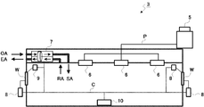
- FIG. 10 is a schematic diagram showing an example of the overall configuration of the air-conditioning system 3 according to Embodiment 3 of the present invention.
- the air conditioning system 3 includes an air conditioning ventilator 7, an outdoor unit 5, a plurality of indoor units 6, a plurality of opening / closing mechanisms 8, a plurality of opening / closing sensors 9, and a management device 10. Composed.
- the air-conditioning ventilator 7, the outdoor unit 5, the indoor unit 6, the opening / closing mechanism 8, and the opening / closing sensor 9 are the same as the air conditioning system 2 of FIG. Nevertheless, it is assumed that the determination unit 401 shown in FIG. 8 described above is excluded from the air-conditioning ventilator 7.
- the air-conditioning ventilator 7, the indoor unit 6, the opening / closing mechanism 8, the opening / closing sensor 9, and the management device 10 are connected to be communicable via the communication line C.
- FIG. 11 is a block diagram for explaining the configuration of the management apparatus 10. As illustrated, the management device 10 includes a communication unit 11 and a control unit 12.
- the communication unit 11 communicates with the air conditioning ventilator 7, the indoor unit 6, the opening / closing mechanism 8, and the opening / closing sensor 9 via the communication line C.
- the communication unit 11 communicates with the air conditioning ventilator 7 and acquires the temperature and humidity detected by the sensor 48 (sensors 48a and 48b).
- the communication unit 11 communicates with the indoor unit 6 and acquires the operating status of the indoor unit 6 (for example, whether a cooling load is generated). Further, the communication unit 11 transmits necessary instructions to the air conditioning ventilator 7 and the opening / closing mechanism 8.
- the control unit 12 includes a determination unit 121 as a determination unit, an estimation unit 122 as an estimation unit, a command unit 123, and a storage unit 124.
- the control part 12 is comprised from CPU, ROM, RAM etc. as an example.
- command part 123 are implement
- the determination unit 121 determines the validity / invalidity of the outside air cooling based on the temperature and humidity by the sensor 48 acquired from the air-conditioning ventilation device 7 by the communication unit 11. For example, the determination unit 121 compares the outdoor air enthalpy obtained from the temperature and humidity of the outdoor air OA detected by the sensor 48a with the indoor air enthalpy obtained from the temperature and humidity of the indoor air RA detected by the sensor 48b. Only when the outdoor air enthalpy is lower than the indoor air enthalpy and a cooling load is generated in the indoor unit 6, it is determined that the outdoor air cooling is effective.
- the estimation unit 122 estimates the power increase amount (ventilation fan power increase amount) ⁇ Wf of the air-conditioning ventilator 7 and the power reduction amount (air-conditioning side power reduction amount) ⁇ W_i of the indoor unit 6 and the outdoor unit 5, and the energy saving effect is obtained.
- the highest ventilation air flow Va1 is determined.
- a procedure until the estimation unit 122 determines the ventilation air volume Va1 will be described with reference to FIGS.
- the supply fan 42 of the air-conditioning ventilator 7 is stopped and only the exhaust fan 44 is driven. At this time, the rotation speed of the exhaust fan 44 (that is, the ventilation air volume Va) is arbitrarily set in the air-conditioning ventilator 7. It is possible to instruct.
- the relationship between the power consumption of the exhaust fan 44 (that is, the ventilation fan power Wf) and the ventilation air volume Va is a non-linear and convex curve as shown in FIG. 12 to 14, Io1 [kJ / kg], Io2 [kJ / kg], Io3 [kJ / kg], and Io4 [kJ / kg] indicate outdoor air enthalpies, and Io1> Io2> The relationship is Io3> Io4. Nevertheless, as shown in FIG. 12, the ventilation fan power Wf does not change depending on the magnitude of the outdoor air enthalpy.
- the outdoor air cooling capacity Q_g [kW] is expressed by the following formula ([ It is expressed by the formula 1]).
- the relationship between the ventilation air volume Va and the outside air cooling capacity Qg is a proportional relationship as shown in FIG. 13, and the inclination increases as the outdoor air enthalpy decreases.
- the slope of Io4 with the lowest outdoor air enthalpy is the largest.
- outside air cooling efficiency COP_g is expressed by the following equation ([Formula 2]).
- the relationship between the ventilation air volume Va and the outside air cooling efficiency COP_g is a non-linear and convex curve as shown in FIG. That is, the lower the ventilation air volume Va, the higher the outdoor air cooling efficiency COP_g, and the lower the outdoor air enthalpy, the higher the outdoor air cooling efficiency COP_g.
- an air volume Va0 is defined as a ventilation air volume Va for maintaining the CO 2 concentration (for example, maintaining it at 1000 ppm or less). Therefore, it is necessary to adjust the ventilation air volume Va to the air volume Va0.
- Q_i0 is the air conditioning side capacity at the time of ventilation air flow Va0.
- Q_g0 is the outside air cooling capacity when the ventilation air volume is Va0.
- Q_i1 is the air conditioning side capacity when the ventilation air volume Va0 is increased.
- Q_g1 is the outside air cooling capacity when the ventilation air volume Va0 is increased.
- the outside air cooling capacity Q_g increases as can be seen from the characteristics of FIG. Referring to the left side of FIG. 15, the outside air cooling capacity Q_g increases by (Q_g1-Q_g0). On the other hand, the air-conditioning side capacity decreases by the amount (Q_g1-Q_g0) in which the outside air cooling capacity Q_g is increased.
- W_i0 shown on the right side of FIG. 15 is the air-conditioning side power consumption when the ventilation airflow is Va0.
- Wf0 is the ventilation fan power at the time of ventilation air volume Va0.
- W_i1 is the air-conditioning side power consumption when increased from the ventilation air volume Va0.
- Wf1 is the ventilation fan power when the ventilation air volume Va0 is increased.
- (Wf1-Wf0), that is, the ventilation fan power increase amount ⁇ Wf can be predicted if the characteristics shown in FIG. 12 are grasped in advance.
- (W_i0-W_i1) that is, for the air conditioning side power reduction amount ⁇ W_i
- the efficiency COP_i0 when the capacity is Q_i0 and the efficiency COP_i1 when the capacity is Q_i1 are estimated.
- W_i0 and W_i1 can be calculated respectively.
- the efficiency on the air conditioning side may be a predetermined efficiency, or may be estimated (estimated) from the operating state, indoor / outdoor temperature conditions, and the like.
- the ventilation air volume Va1 at which ⁇ W_i ⁇ Wf is maximized is a point having the highest outdoor air cooling effect (high energy saving effect). That is, when the ventilation air volume Va1 is increased, the difference between the air conditioning side power reduction amount ⁇ W_i and the ventilation fan power increase amount ⁇ Wf is maximized. Therefore, the estimation unit 122 determines the ventilation air volume Va1 at which ⁇ W_i ⁇ Wf is maximized. The ventilation air volume Va1 determined in this way is commanded by the command unit 123 described below as the air flow rate of the exhaust fan 44 to be adjusted by the air conditioning ventilator 7.
- the command unit 123 controls the communication unit 11 to send necessary commands to the air-conditioning ventilator 7 and the opening / closing mechanism 8. For example, when the determination unit 121 determines that the outside air cooling is effective, the command unit 123 sends a command to start the outside air cooling to the air conditioning ventilator 7 and sends an opening command to the opening and closing mechanism 8. The door W is opened. Further, the command unit 123 causes the air conditioning ventilator 7 to adjust the air flow rate of the exhaust fan 44 so that the ventilation air volume Va1 determined by the estimation unit 122 is obtained.
- the storage unit 124 stores various information necessary for controlling the entire system.
- the storage unit 124 stores a program for executing an outside air cooling control process (FIG. 16) described later.
- FIG. 16 is a flowchart illustrating an example of an outside air cooling control process executed by the management apparatus 10 (the control unit 12). This outside air cooling control process is repeatedly executed, for example, every time a predetermined time elapses.
- the control unit 12 acquires outdoor and indoor temperature and humidity (step S301). That is, the control unit 12 controls the communication unit 11 to acquire the temperature and humidity of the outdoor air OA by the sensor 48a and the temperature and humidity of the indoor air RA by the sensor 48b from the air conditioning ventilator 7.
- the control unit 12 determines whether or not the outside air cooling is effective (step S302). For example, the determination unit 121 compares the outdoor air enthalpy obtained from the temperature and humidity of the outdoor air OA with the indoor air enthalpy obtained from the temperature and humidity of the indoor air RA, and the outdoor air enthalpy is lower than the indoor air enthalpy, and Only when the cooling load is generated in the indoor unit 6, it is determined that the outside air cooling is effective.
- step S302 When it is determined that the outside air cooling is effective (step S302; Yes), the control unit 12 opens the door W (step S303). That is, the command unit 123 sends an opening command to the opening / closing mechanism 8 through the communication unit 11 to open the door W. If it is detected by the open / close sensor 9 that the door W has already been opened, the control unit 12 skips the process of step S303.
- the control unit 12 instructs the start of outside air cooling (step S304). That is, the command unit 123 sends a command for starting the outside air cooling to the air conditioning ventilator 7 through the communication unit 11. In response to this command, the air-conditioning ventilator 7 opens the damper 47 and stops the air supply fan 42.
- control unit 12 skips the process of step S304.
- the control unit 12 estimates the ventilation fan power increase amount ⁇ Wf and the air conditioning side power reduction amount ⁇ W_i, and determines the ventilation air volume Va1 that maximizes the energy saving effect (step S305). That is, the estimation unit 122 estimates ⁇ Wf and ⁇ W_i using the above-described mathematical formulas ([Expression 1] to [Expression 3]), and determines the ventilation air volume Va1 that maximizes ⁇ W_i ⁇ Wf.
- the controller 12 determines whether or not the ventilation air volume Va1 is larger than the ventilation air volume Va0 (step S306). That is, the controller 12 determines whether or not the ventilation air volume Va1 determined in step S305 is larger than the ventilation air volume Va0 for maintaining the CO 2 concentration. When it is determined that the ventilation air volume Va1 is not greater than (or less than) the ventilation air volume Va0 (step S306; No), the control unit 12 ends the outside air cooling control process.
- the control unit 12 transmits an adjustment command for the ventilation air volume Va1 to the air conditioning ventilator 7 (step S307). That is, the command unit 123 causes the air-conditioning ventilator 7 to adjust the air volume of the exhaust fan 44 so that the ventilation air volume Va1 is obtained.
- step S302 when it is determined in step S302 described above that the outside air cooling is not effective (invalid) (step S302; No), the control unit 12 closes the door W (step S308). That is, the command unit 123 sends a close command to the opening / closing mechanism 8 through the communication unit 11 to close the door W. If it is detected by the opening / closing sensor 9 that the door W has already been closed, the control unit 12 skips the process of step S308.
- the control unit 12 instructs the end of the outside air cooling (step S309). That is, the command unit 123 sends a command for terminating the outside air cooling to the air conditioning ventilator 7 through the communication unit 11. In response to this command, the air-conditioning ventilator 7 closes the damper 47 and drives the air supply fan 42. Furthermore, when the air volume of the exhaust fan 44 is changed (adjusted), the air conditioning ventilator 7 returns the air volume of the exhaust fan 44.
- control unit 12 skips the process of step S309 and ends the outside air cooling control process.
- the supply air fan 42 is stopped during the cooling of the outside air, the power of the blower can be reduced. Further, when the outside air cooling is performed, the ventilation air volume Va1 that maximizes the energy saving effect is determined, and the air volume of the exhaust fan 44 is adjusted so as to be the ventilation air volume Va1, so that the energy saving performance during the outside air cooling is appropriately improved. be able to.
- the ventilation air volume of the exhaust fan 44 is increased in order to enhance the outside air cooling effect.
- the ventilation air volume may be increased by other methods.
- the ventilation air volume may be increased by enlarging the bypass air passage 46 or enlarging the fan diameter of the exhaust fan 44.
- the ventilation air volume since it is only necessary to perform one side (in the first to third embodiments, the exhaust air passage 43 side), it is possible to suppress an increase in the housing size of the air-conditioning ventilators 4 and 7.
- the case where the dedicated air-conditioning ventilators 4 and 7 are used, and in the third embodiment described above, the case where the dedicated management device 10 is used has been described.
- the personal computer can function as the air-conditioning ventilators 4 and 7 and the management apparatus 10.
- a program distribution method is arbitrary.
- a computer-readable medium such as a CD-ROM (Compact Disk Read-Only Memory), a DVD (Digital Versatile Disk), an MO (Magneto Optical Disk), or a memory card is readable. It may be stored in a recording medium and distributed, or distributed via a communication network such as the Internet.
- the present invention can be employed in an air-conditioning ventilator, an air-conditioning system, and a control method that can appropriately improve energy saving during outdoor air cooling.
- Air conditioning system 1, 2, 3 Air conditioning system, 4, 7 Air conditioning ventilator, 5 Outdoor unit, 6 Indoor unit, 8 Opening / closing mechanism, 9 Opening / closing sensor, 10 Management device, 11, 71 Communication unit, 12, 40, 70 Control unit, 41 air supply path, 42 air supply fan, 43 exhaust air path, 44 exhaust fan, 45 total heat exchanger, 46 bypass air path, 47 damper, 48a, 48b sensor, 121, 401 determination unit, 122 estimation unit, 123, 402,702 command section, 124,403 storage section
Landscapes
- Engineering & Computer Science (AREA)
- Chemical & Material Sciences (AREA)
- Combustion & Propulsion (AREA)
- Mechanical Engineering (AREA)
- General Engineering & Computer Science (AREA)
- Air Conditioning Control Device (AREA)
- Ventilation (AREA)
Abstract
制御部(40)は、センサ(48a,48b)が検出した温湿度に基づいて、室外の空気を室内に取り入れる外気冷房が有効であるか否かを判別する。制御部(40)は、外気冷房が有効であると判別すると、ダンパ(47)を開放すると共に、給気風路41に配置された給気ファン42を停止させる。これにより、排気風路(43)を通過する室内空気(RA)は、バイパス風路(46)を通ることで、全熱交換器(45)を迂回し、排出空気(EA)として室外に排出される。一方、給気ファン(42)を停止しているため、給気風路(41)には、室外空気(OA)が流れないものの、建物の開口部から室外空気(OA)が流れ込む。
Description
本発明は、外気冷房時における省エネルギー性を適切に向上させることのできる空調換気装置、空気調和システム、および、制御方法に関する。
従来より、ビルに代表される建物内には、空気調和システムが導入されている。この空気調和システムには、一例として、熱交換器(全熱交換器、または、顕熱交換器)を備えた換気装置が含まれており、室内空気を室外空気(新鮮空気)と入れ替える際に生じる空調負荷を低減することができる。例えば、夏期であれば、高温の室外空気をそのまま取り入れると、室内温度が大きく上昇してしまうが、換気装置の熱交換器により室内空気と熱交換することで、冷却された室外空気が室内に供給される。このため、室内温度の上昇が抑制され、空調負荷が低減される。
このような換気装置を備えた空調システムの発明が、例えば、特許文献1に開示されている。この発明では、中間期(春、秋)のように、室外温度が室内温度よりも低い場合に、熱交換器をバイパスさせて、低温の室外空気を室内にそのまま取り入れることで、外気冷房効果が得られる。これにより、空調システムの空調負荷を減らして、省エネルギー性を向上させようというものである。
しかしながら、上述した特許文献1の発明において、外気冷房効果を高めるためには、換気風量をある程度まで増大させる必要がある。つまり、実際の外気冷房時には、換気装置において、ファンの送風量を増大させることで、その分の消費電力量が増大してしまう。このため、空調負荷を減らした分を考慮しても、省エネルギー性の向上にあまり有効ではなかった。
そこで、外気冷房時において、省エネルギー性を適切に向上させることのできる技術が求められていた。
本発明は、上記のような問題点を解決するためになされたもので、外気冷房時における省エネルギー性を適切に向上させることを目的とする。
上記目的を達成するため、本発明に係る空調換気装置は、
第1の送風手段が配置され、室外の空気を室内に供給するための第1の風路と、
第2の送風手段が配置され、室内の空気を室外に排出するための第2の風路と、
前記第1の風路を通過する空気と前記第2の風路を通過する空気との間で熱交換を行う熱交換手段と、
前記第1及び第2の風路の何れか一方と接合して形成され、前記熱交換手段を迂回するためのバイパス風路と、
前記バイパス風路を開閉して、通過する空気の風路を切り替える風路切替手段と、
前記第1及び第2の送風手段、並びに、前記風路切替手段を制御する制御手段とを備え、
前記制御手段は、室外の空気を室内に取り入れる外気冷房時において、前記風路切替手段を制御して前記バイパス風路を開放すると共に、前記バイパス風路が形成されていない方の風路に配置された前記送風手段を停止させる。
本発明によれば、外気冷房時において、制御手段が風路切替手段を制御してバイパス風路を開放すると共に、バイパス風路が形成されていない方の風路に配置された送風手段を停止させる。この結果、外気冷房時における省エネルギー性を適切に向上させることができる。
以下、本発明の実施形態について、図面を参照しながら詳細に説明する。なお、図中同一又は相当部分には同一符号を付す。以下では、具体例として、本発明が換気を主機能とした空調換気装置(空気調和システム)に適用される場合について説明するが、空気調和を主機能とした空気調和装置においても同様に本発明を適用することができる。すなわち、以下に説明する実施形態は説明のためのものであり、本発明の範囲を制限するものではない。従って、当業者であればこれらの各要素又は全要素をこれと均等なものに置換した実施形態を採用することが可能であるが、これらの実施形態も本発明の範囲に含まれる。
(実施形態1)
図1は、本発明の実施形態1に係る空気調和システム1の全体構成の一例を示す模式図である。この空気調和システム1は、例えば、ビルに代表される建物に設置されており、図示するように、空調換気装置4と、室外機5と、複数の室内機6とを含んで構成される。室外機5と複数の室内機6とは、配管Pを通じて接続されている。なお、室外機5及び室内機6の数は一例であり、例えば、建物(フロア)の床面積に応じて、適宜変更可能である。
図1は、本発明の実施形態1に係る空気調和システム1の全体構成の一例を示す模式図である。この空気調和システム1は、例えば、ビルに代表される建物に設置されており、図示するように、空調換気装置4と、室外機5と、複数の室内機6とを含んで構成される。室外機5と複数の室内機6とは、配管Pを通じて接続されている。なお、室外機5及び室内機6の数は一例であり、例えば、建物(フロア)の床面積に応じて、適宜変更可能である。
空調換気装置4は、例えば、建物の天井裏に設置されており、室内の空気と室外の空気とを入れ換える。つまり、空調換気装置4は、室外空気OAを供給空気SAとして室内に供給すると共に、室内空気RAを排出空気EAとして室外に排出する。以下、図2を参照して、空調換気装置4の外観構成を説明する。
図2は、空調換気装置4の外観構成を説明するための模式図である。図示するように、空調換気装置4は、制御手段としての制御部40と、第1の風路としての給気風路41と、第1の送風手段としての給気ファン42と、第2の風路としての排気風路43と、第2の送風手段としての排気ファン44と、熱交換手段としての全熱交換器45と、バイパス風路46と、風路切替手段としてのダンパ47と、センサ48(48a,48b)と、を含んで構成される。
制御部40は、空調換気装置4全体を制御する。なお、制御部40の詳細については、後述する図3と共に説明する。
給気風路41は、室外空気OAを供給空気SAとして室内に供給するための風路であり、給気ファン42が配置されている。この給気ファン42は、制御部40に制御されて駆動(回転)し、室外空気OAを給気風路41内に取り込む。
排気風路43は、室内空気RAを排出空気EAとして室外に排出するための風路であり、排気ファン44が配置されている。この排気ファン44は、制御部40に制御されて駆動し、室内空気RAを排気風路43内に取り込む。
全熱交換器45は、給気風路41を通過する室外空気OAと、排気風路43を通過する室内空気RAとの間で全熱交換を行う。全熱交換後の室外空気OAは、供給空気SAとして室内に供給され、一方、全熱交換後の室内空気RAは、排出空気EAとして室外に排出される。なお、全熱交換器45の代わりに、顕熱交換器を用いてもよい。
バイパス風路46は、排気風路43と接合して形成されており、排気風路43を通過する室内空気RAが、全熱交換器45を通らずに迂回するための風路として用いることができる。なお、バイパス風路46は、バイパス風路46を通過する際の風路抵抗が、全熱交換器45を通過する際の風路抵抗と比べて低くなる(一例として、1/2の抵抗)となるように形成されている。
このバイパス風路46と排気風路43との一方の接合部(一例として、室内側の接合部)には、ダンパ47が配置されている。このダンパ47は、制御部40に制御されて開閉し、排気風路43を通過する室内空気RAの風路を切り替える。つまり、ダンパ47を閉じると、室内空気RAは全熱交換器45通過する。一方、ダンパ47を開くと、室内空気RAはバイパス風路46を通過する(つまり、全熱交換器45を通らずに迂回する)。
なお、本発明の実施形態(実施形態1~3)では、バイパス風路46が、排気風路43と接合して形成されている場合について説明するが、一例であり、これとは逆に、バイパス風路46が、給気風路41と接合して形成されていてもよい。その場合、バイパス風路46は、給気風路41を通過する室外空気OAが、全熱交換器45を通らずに迂回するための風路として用いられることとなる。
センサ48(48a,48b)は、例えば、温湿度センサであり、給気風路41(一例として、室外側近傍)と、排気風路43(一例として、室内側近傍)とに配置されている。センサ48aは、給気風路41を通過する室外空気OAの温湿度を検出し、そのデータ(検出結果)を制御部40に供給する。一方、センサ48bは、排気風路43を通過する室内空気RAの温湿度を検出し、そのデータを制御部40に供給する。なお、センサ48は、温度だけを検出する温度センサであってもよい。
次に、図3を参照して、主に空調換気装置4の制御部40について説明する。図3は、空調換気装置4の接続構成を説明するためのブロック図である。図示するように、制御部40は、判定手段としての判定部401と、指令部402と、記憶部403とを含んで構成される。なお、制御部40は、一例として、CPU(Central Processing Unit),ROM(Read Only Memory),RAM(Random Access Memory)等から構成される。そして、判定部401及び指令部402は、例えば、CPUが、RAMをワークメモリとして用い、ROMに記憶されている各種プログラムを適宜実行することにより実現される。
判定部401は、センサ48による検出結果に基づいて、室外空気OAを室内に取り入れる外気冷房の有効無効を判定する。例えば、判定部401は、センサ48aが検出した室外空気OAの温湿度から求まる室外空気エンタルピと、センサ48bが検出した室内空気RAの温湿度から求まる室内空気エンタルピとを比較する。そして、室外空気エンタルピの方が室内空気エンタルピよりも低い場合に、判定部401は、外気冷房が有効と判定する。一方、その逆の場合に、判定部401は、外気冷房が無効と判定する。なお、空調換気装置4(制御部40)が、室内機6の運転状況を得られる場合に、判定部401は、室内機6が冷房運転しているか(冷房負荷が発生しているか)どうかも含めて、外気冷房の有効無効を判定する。つまり、判定部401は、室外空気エンタルピの方が室内空気エンタルピよりも低く、かつ、冷房負荷が発生している場合に限り、外気冷房が有効と判定する。
指令部402は、例えば、ダンパ47を駆動させるアクチュエータ、給気ファン42を回転させるモータドライバ、及び、排気ファン44を回転させるモータドライバに、必要な指令を送る。具体的には、判定部401によって外気冷房が有効と判定された場合に、指令部402は、外気冷房を行うための指令を送る。つまり、指令部402は、ダンパ47のアクチュエータに開指令を送ってダンパ47を開放すると共に、給気ファン42のモータドライバに停止指令を送って給気ファン42を停止させる。更に、指令部402は、排気ファン44のモータドライバに強回転指令を送って排気ファン44の風量を増大させてもよい。
このようにして、外気冷房が開始されると、空調換気装置4では、図4に示すように、ダンパ47が開放され、排気風路43を通過する室内空気RAは、バイパス風路46を通り(全熱交換器45を迂回し)、排出空気EAとして室外に排出される。一方、給気ファン42を停止しているため、給気風路41には、室外空気OAが流れない。
室外空気OAは、図5に示すように、窓や扉に代表される開口部OPを通り、室内に流れ込む。つまり、空調換気装置4が室内空気RAを排出空気EAとして室外に排出することで、室外空気OAが開口部OPを通り、室内に流れ込むことになる。
図3に戻って、記憶部403は、空調換気装置4の制御に必要な種々の情報を記憶する。例えば、記憶部403は、後述する外気冷房制御処理を実行するためのプログラムを記憶する。
図1に戻って、室外機5は、例えば、圧縮機および熱源側熱交換器を有しており、配管Pによって室内機6と接続されている。そして、室外機5は、この配管Pを通じて室内機6との間で冷媒を循環させる。なお、室外機5は、室外(一例として、建物の屋上)に設置されている。
室内機6は、例えば、膨張弁および負荷側熱交換器を有しており、配管Pによって室外機5と接続されている。そして、室内機6は、この配管Pを通じて室外機5から送られた冷媒を、負荷側熱交換器において蒸発または凝縮させることにより、室内(対象空間)の空気調和を行う。この室内機6は、例えば、建物(フロア)の天井版に埋め込まれて設置されている。
以下、空気調和システム1における空調換気装置4の動作について、図6を参照して説明する。図6は、空調換気装置4(制御部40)が実行する外気冷房制御処理の一例を示すフローチャートである。この外気冷房制御処理は、例えば、一定時間が経過する毎に、繰り返し実行される。
まず、制御部40は、室外及び室内の温湿度を取得する(ステップS101)。すなわち、制御部40は、センサ48aから室外空気OAの温湿度を取得し、また、センサ48bから室内空気RAの温湿度を取得する。
制御部40は、外気冷房が有効であるか否かを判別する(ステップS102)。すなわち、判定部401は、ステップS101にて取得した温湿度に基づいて、外気冷房の有効無効を判定する。例えば、判定部401は、室外空気OAの温湿度から求まる室外空気エンタルピと、室内空気RAの温湿度から求まる室内空気エンタルピとを比較する。そして、室外空気エンタルピの方が室内空気エンタルピよりも低い場合に、判定部401は、外気冷房が有効と判定する。一方、その逆の場合に、判定部401は、外気冷房が無効と判定する。なお、上述したように、室内機6の運転状況が得られる場合では、判定部401は、室内機6が冷房運転しているか(冷房負荷が発生しているか)どうかも含めて、外気冷房の有効無効を判定する。つまり、判定部401は、室外空気エンタルピの方が室内空気エンタルピよりも低く、かつ、冷房負荷が発生している場合に限り、外気冷房が有効と判定する。
制御部40は、外気冷房が有効であると判別すると(ステップS102;Yes)、ダンパ47を開放すると共に、給気ファン42を停止させる(ステップS103)。すなわち、指令部402は、ダンパ47を駆動させるアクチュエータに開指令を送ってダンパ47を開放すると共に、給気ファン42を回転させるモータドライバに停止指令を送って給気ファン42を停止させる。更に、指令部402は、排気ファン44を回転させるモータドライバに強回転指令を送って排気ファン44の風量を増大させてもよい。
なお、既に外気冷房中であれば(ダンパ47を開放済みであり、また、給気ファン42を停止済みであれば)、制御部40は、ステップS103の処理をスキップし、外気冷房制御処理を終える。
このようにして、外気冷房が開始されると、上述した図4のように、空調換気装置4では、ダンパ47が開放され、排気風路43を通過する室内空気RAは、バイパス風路46を通り(全熱交換器45を迂回し)、排出空気EAとして室外に排出される。一方、給気ファン42を停止しているため、給気風路41には、室外空気OAが流れない。
室外空気OAは、上述した図5のように、開口部OPを通り、室内に流れ込む。つまり、空調換気装置4が室内空気RAを排出空気EAとして室外に排出することで、室外空気OAが開口部OPを通り、室内に流れ込むことになる。
一方、上述したステップS102にて、外気冷房が有効でない(無効である)と判別した場合(ステップS102;No)に、制御部40は、ダンパ47を閉鎖すると共に、給気ファン42を駆動(回転)させる(ステップS104)。すなわち、指令部402は、ダンパ47を駆動させるアクチュエータに閉指令を送ってダンパ47を閉鎖すると共に、給気ファン42を回転させるモータドライバに回転指令を送って、停止させていた給気ファン42を駆動させる。更に、排気ファン44の風量を増大させている場合には、指令部402は、排気ファン44を回転させるモータドライバに回転復帰指令を送って排気ファン44の風量を戻す。
なお、外気冷房中でなければ(ダンパ47を閉鎖済みであり、また、給気ファン42を駆動済みであれば)、制御部40は、ステップS104の処理をスキップし、外気冷房制御処理を終える。
このように、外気冷房時において、給気ファン42(つまり、バイパス風路46が形成されていない方の風路に配置された送風手段)を停止させるため、送風機動力を低減することができる。また、外気冷房時において、外気冷房効果を高めるために、排気ファン44(つまり、バイパス風路46が形成されている方の風路に配置された送風手段)の換気風量を増加させたとしても、給気ファン42を停止させているため、空調換気装置4全体の送風機動力は、外気冷房前に比べて増加しない。この結果、外気冷房時における省エネルギー性を適切に向上させることができる。
(実施形態2)
上記の実施形態1では、図5に示すような開口部OPを利用できる場合について説明したが、窓、ドア等が全て閉じられている場合には、このような開口部OPを利用できない。そのため、システム側で窓、ドア等の開閉制御が行えるようにしてもよい。以下、本発明の実施形態2について説明する。
上記の実施形態1では、図5に示すような開口部OPを利用できる場合について説明したが、窓、ドア等が全て閉じられている場合には、このような開口部OPを利用できない。そのため、システム側で窓、ドア等の開閉制御が行えるようにしてもよい。以下、本発明の実施形態2について説明する。
図7は、本発明の実施形態2に係る空気調和システム2の全体構成の一例を示す模式図である。図示するように、この空気調和システム2は、空調換気装置7と、室外機5と、複数の室内機6と、複数の開閉機構8と、複数の開閉センサ9とを含んで構成される。なお、室外機5、及び、室内機6は、図1の空気調和システム1と同様である。また、空調換気装置7、開閉機構8、及び、開閉センサ9は、通信線Cを介して通信可能に接続されている。更に、開閉機構8及び開閉センサ9の数は一例であり、適宜変更可能である。
開閉手段としての開閉機構8は、通信線Cを通じて空調換気装置7に制御され、建物に設けられた扉部W(一例として、窓,ドア等)を開閉する。なお、開閉機構8は、ユーザによる手動操作に応じても、扉部Wを開閉可能となっている。
開閉センサ9は、扉部Wの開閉状態を検出し、通信線Cを介して空調換気装置7に通知する。
図8は、空調換気装置7の接続構成を説明するためのブロック図である。なお、空調換気装置7の外観構成は、上述した図3の空調換気装置4と同様である。図8に示すように、制御部70は、判定部401と、指令部702と、記憶部403とを含んで構成される。なお、判定部401、及び、記憶部403は、図3の空調換気装置4と同様である。
また、空調換気装置7は、通信部71を更に備えている。この通信部71は、制御部70に制御され、開閉機構8、及び、開閉センサ9と通信を行う。
指令部702は、給気ファン42、排気ファン44、及び、ダンパ47に指令を送るだけでなく、通信部71を通じて、開閉機構8に対しても指令を送る。例えば、判定部401によって外気冷房が有効と判定された場合に、指令部702は、通信部71を通じて、開閉機構8に開指令を送って、扉部Wを開放させる。また、通信部71が、開閉センサ9と通信して、扉部Wの開閉状態を取得するため、指令部702は、扉部Wの開閉状態も参照することができる。
以下、空気調和システム2における空調換気装置7の動作について、図9を参照して説明する。図9は、空調換気装置7(制御部70)が実行する外気冷房制御処理の一例を示すフローチャートである。この外気冷房制御処理は、例えば、一定時間が経過する毎に、繰り返し実行される。
まず、制御部70は、室外及び室内の温湿度を取得する(ステップS201)。すなわち、制御部70は、センサ48aから室外空気OAの温湿度を取得し、また、センサ48bから室内空気RAの温湿度を取得する。
制御部70は、外気冷房が有効であるか否かを判別する(ステップS202)。例えば、判定部401は、室外空気OAの温湿度から求まる室外空気エンタルピと、室内空気RAの温湿度から求まる室内空気エンタルピとを比較し、室外空気エンタルピの方が室内空気エンタルピよりも低い場合に、判定部401は、外気冷房が有効と判定する。なお、上記と同様に室内機6の運転状況が得られる場合では、判定部401は、室外空気エンタルピの方が室内空気エンタルピよりも低く、かつ、冷房負荷が発生している場合に限り、外気冷房が有効と判定する。
制御部70は、外気冷房が有効であると判別すると(ステップS202;Yes)、扉部Wを開放する(ステップS203)。すなわち、指令部702は、通信部71を通じて、開閉機構8に開指令を送って、扉部Wを開放させる。なお、開閉センサ9により既に扉部Wが開放済みであると検出されていれば、制御部70は、ステップS203の処理をスキップする。
制御部70は、ダンパ47を開放すると共に、給気ファン42を停止させる(ステップS204)。すなわち、指令部702は、ダンパ47を駆動させるアクチュエータに開指令を送ってダンパ47を開放すると共に、給気ファン42を回転させるモータドライバに停止指令を送って給気ファン42を停止させる。更に、指令部702は、排気ファン44を回転させるモータドライバに強回転指令を送って排気ファン44の風量を増大させてもよい。
なお、既に外気冷房中であれば(ダンパ47を開放済みであり、また、給気ファン42を停止済みであれば)、制御部70は、ステップS204の処理をスキップし、外気冷房制御処理を終える。
一方、上述したステップS202にて、外気冷房が有効でない(無効である)と判別した場合(ステップS202;No)に、制御部70は、扉部Wを閉鎖する(ステップS205)。すなわち、指令部702は、通信部71を通じて、開閉機構8に閉指令を送って扉部Wを閉鎖する。なお、開閉センサ9により既に扉部Wが閉鎖済みであると検出されていれば、制御部70は、ステップS205の処理をスキップする。
制御部70は、ダンパ47を閉鎖すると共に、給気ファン42を駆動させる(ステップS206)。すなわち、指令部702は、ダンパ47を駆動させるアクチュエータに閉指令を送ってダンパ47を閉鎖すると共に、給気ファン42を回転させるモータドライバに回転指令を送って給気ファン42を駆動させる。更に、排気ファン44の風量を増大させている場合には、指令部702は、排気ファン44を回転させるモータドライバに回転復帰指令を送って排気ファン44の風量を戻す。
なお、外気冷房中でなければ(ダンパ47を閉鎖済みであり、また、給気ファン42を駆動済みであれば)、制御部70は、ステップS206の処理をスキップし、外気冷房制御処理を終える。
このように、外気冷房時において、給気ファン42を停止させるため、送風機動力を低減することができる。また、外気冷房時において、外気冷房効果を高めるために、排気ファン44の換気風量を増加させたとしても、給気ファン42を停止させているため、空調換気装置7全体の送風機動力は、外気冷房前に比べて増加しない。この結果、外気冷房時における省エネルギー性を適切に向上させることができる。また、扉部Wが閉鎖されていても、外気冷房の開始と共に、扉部Wを確実に開放することができる。
(実施形態3)
上記の実施形態1,2では、空調換気装置4,7が外気冷房の制御を行う場合について説明したが、システム全体を管理する管理装置(コントローラ)が、外気冷房の制御を行うようにしてもよい。以下、本発明の実施形態3について説明する。
上記の実施形態1,2では、空調換気装置4,7が外気冷房の制御を行う場合について説明したが、システム全体を管理する管理装置(コントローラ)が、外気冷房の制御を行うようにしてもよい。以下、本発明の実施形態3について説明する。
図10は、本発明の実施形態3に係る空気調和システム3の全体構成の一例を示す模式図である。図示するように、この空気調和システム3は、空調換気装置7と、室外機5と、複数の室内機6と、複数の開閉機構8と、複数の開閉センサ9と、管理装置10を含んで構成される。なお、空調換気装置7、室外機5、室内機6、開閉機構8、及び、開閉センサ9は、図7の空気調和システム2と同様である。それでも、空調換気装置7からは、上述した図8に示す判定部401が除かれているものとする。また、空調換気装置7、室内機6、開閉機構8、開閉センサ9、及び、管理装置10は、通信線Cを介して通信可能に接続されている。
図11は、管理装置10の構成を説明するためのブロック図である。図示するように、管理装置10は、通信部11と、制御部12とを含んで構成される。
通信部11は、通信線Cを介して、空調換気装置7、室内機6、開閉機構8、及び、開閉センサ9と通信を行う。例えば、通信部11は、空調換気装置7と通信して、センサ48(センサ48a,48b)が検出した温湿度を取得する。また、通信部11は、室内機6と通信して、室内機6の運転状況(一例として、冷房負荷が発生しているか)を取得する。更に、通信部11は、空調換気装置7、及び、開閉機構8に必要な指令を送信する。
制御部12は、判定手段としての判定部121と、推定手段としての推定部122と、指令部123と、記憶部124とを含んで構成される。なお、制御部12は、一例として、CPU,ROM,RAM等から構成される。そして、判定部121、推定部122、及び、指令部123は、例えば、CPUが、RAMをワークメモリとして用い、ROMに記憶されている各種プログラムを適宜実行することにより実現される。
判定部121は、通信部11が空調換気装置7から取得したセンサ48による温湿度に基づいて、外気冷房の有効無効を判定する。例えば、判定部121は、センサ48aが検出した室外空気OAの温湿度から求まる室外空気エンタルピと、センサ48bが検出した室内空気RAの温湿度から求まる室内空気エンタルピとを比較する。そして、室外空気エンタルピの方が室内空気エンタルピよりも低く、かつ、室内機6にて冷房負荷が発生している場合に限り、外気冷房が有効と判定する。
推定部122は、空調換気装置7の電力増加量(換気送風機動力増加量)ΔWf、及び、室内機6及び室外機5の電力削減量(空調側電力削減量)ΔW_iを推定し、省エネルギー効果が最も高くなる換気風量Va1を決定する。以下、推定部122が、換気風量Va1を決定するまでの手順について、図12~図15を参照して説明する。
外気冷房において、空調換気装置7の給気ファン42を停止し、排気ファン44だけを駆動させるが、この際、空調換気装置7に排気ファン44の回転数(すなわち、換気風量Va)を任意に指示することが可能となっている。
この際、排気ファン44の消費電力(すなわち換気送風機動力Wf)と、換気風量Vaとの関係は、図12に示すように、非線形で下に凸の曲線となる。なお、図12~図14において、Io1[kJ/kg]、Io2[kJ/kg]、Io3[kJ/kg]、Io4[kJ/kg]は、室外空気エンタルピを示しており、Io1>Io2>Io3>Io4の関係となっている。それでも、図12に示すように、換気送風機動力Wfは、室外空気エンタルピの大小によっては、変化しない。
室内空気エンタルピをIi[kJ/kg]、室外空気エンタルピをIo[kJ/kg]、空気の密度をρa[kg/m3]とすると、外気冷房能力Q_g[kW]は、以下の数式([数1])により表される。
[数1]
Q_g = Va/3600×ρa×(Ii-Io)
Q_g = Va/3600×ρa×(Ii-Io)
そして、換気風量Vaと外気冷房能力Qgとの関係は、図13に示すように、比例関係となり、室外空気エンタルピが低いほど、傾きが大きくなる。図13の例では、室外空気エンタルピが最も低いIo4の傾きが一番大きくなる。
また、外気冷房効率COP_gは、以下の数式([数2])により表される。
[数2]
COP_g = Q_g/Wf
COP_g = Q_g/Wf
そして、換気風量Vaと外気冷房効率COP_gとの関係は、図14に示すように、非線形で下に凸の曲線となる。つまり、換気風量Vaが低いほど外気冷房効率COP_gは高くなり、また、室外空気エンタルピが低いほど外気冷房効率COP_gは高くなる。
また、CO2濃度を維持する(一例として、1000ppm以下に維持する)ための換気風量Vaとして、風量Va0が定められている。そのため、換気風量Vaを、風量Va0に調整する必要がある。
外気冷房時の能力と消費電力は、図15の左側に示す通りとなる。ここで、Q_i0は、換気風量Va0時の空調側能力である。また、Q_g0は、換気風量Va0時の外気冷房能力である。また、Q_i1は、換気風量Va0から増加させたときの空調側能力である。そして、Q_g1は、換気風量Va0から増加させたときの外気冷房能力である。
換気風量Vaを増加させたとき、図13の特性からも分かる通り、外気冷房能力Q_gは増加する。図15の左側にて説明すると、外気冷房能力Q_gは、(Q_g1-Q_g0)分だけ増加する。一方、空調側能力は、外気冷房能力Q_gが増加した(Q_g1-Q_g0)分だけ減少する。
一方、図15の右側に示すW_i0は、換気風量Va0時の空調側消費電力である。また、Wf0は、換気風量Va0時の換気送風機動力である。また、W_i1は、換気風量Va0から増加させたときの空調側消費電力である。そして、Wf1は、換気風量Va0から増加させたときの換気送風機動力である。
換気風量Vaを増加させたとき、図12の特性からも分かる通り、換気送風機動力Wfは増加する。図15の右側にて説明すると、換気送風機動力Wfは、(Wf1-Wf0)分だけ増加する。一方、空調側消費電力は、(W_i0-W_i1)分だけ減少する。なお、本願において、換気送風機動力増加量ΔWf=(Wf1-Wf0)と表し、また、空調側電力削減量ΔW_i=(W_i0-W_i1)と表すものとする。
ここで、(Wf1-Wf0)、つまり、換気送風機動力増加量ΔWfについては、図12の特性を予め把握しておけば、予測可能である。一方、(W_i0-W_i1)、つまり、空調側電力削減量ΔW_iについては、能力Q_i0のときの効率COP_i0と、能力Q_i1のときの効率COP_i1を推定し、以下の数式([数3])により、W_i0、W_i1をそれぞれ算出することが可能である。
[数3]
W_i0 = Q_i0/COP_i0
W_i1 = Q_i1/COP_i1
W_i0 = Q_i0/COP_i0
W_i1 = Q_i1/COP_i1
なお、空調側効率は、予め決められた効率を用いても良いし、また、運転状態、室内外温度条件等から推定(推算)しても良い。
ここで、ΔW_i-ΔWfが最大となる換気風量Va1は、最も外気冷房効果が高い(省エネルギー効果が高い)ポイントとなる。つまり、換気風量Va1まで増加させたときに、空調側電力削減量ΔW_iと換気送風機動力増加量ΔWfとの差が最大となる。そのため、推定部122は、ΔW_i-ΔWfが最大となる換気風量Va1を決定する。このようにして決定された換気風量Va1は、以下に説明する指令部123によって、空調換気装置7が調整すべき排気ファン44の送風量として指令される。
指令部123は、通信部11を制御して、空調換気装置7、及び、開閉機構8に対して、必要な指令を送る。例えば、判定部121によって外気冷房が有効と判定された場合に、指令部123は、空調換気装置7に対して、外気冷房を開始させる指令を送ると共に、開閉機構8に開指令を送って、扉部Wを開放させる。更に、指令部123は、空調換気装置7に対して、推定部122が決定した換気風量Va1となるように、排気ファン44の送風量を調整させる。
記憶部124は、システム全体の制御に必要な種々の情報を記憶する。例えば、記憶部124は、後述する外気冷房制御処理(図16)を実行するためのプログラムを記憶する。
以下、空気調和システム3における管理装置10の動作について、図16を参照して説明する。図16は、管理装置10(制御部12)が実行する外気冷房制御処理の一例を示すフローチャートである。この外気冷房制御処理は、例えば、一定時間が経過する毎に、繰り返し実行される。
まず、制御部12は、室外及び室内の温湿度を取得する(ステップS301)。すなわち、制御部12は、通信部11を制御して、空調換気装置7から、センサ48aによる室外空気OAの温湿度を取得し、また、センサ48bによる室内空気RAの温湿度を取得する。
制御部12は、外気冷房が有効であるか否かを判別する(ステップS302)。例えば、判定部121は、室外空気OAの温湿度から求まる室外空気エンタルピと、室内空気RAの温湿度から求まる室内空気エンタルピとを比較し、室外空気エンタルピの方が室内空気エンタルピよりも低く、かつ、室内機6にて冷房負荷が発生している場合に限り、外気冷房が有効と判定する。
制御部12は、外気冷房が有効であると判別すると(ステップS302;Yes)、扉部Wを開放する(ステップS303)。すなわち、指令部123は、通信部11を通じて、開閉機構8に開指令を送って扉部Wを開放する。なお、開閉センサ9により既に扉部Wが開放済みであると検出されていれば、制御部12は、ステップS303の処理をスキップする。
制御部12は、外気冷房の開始を指示する(ステップS304)。すなわち、指令部123は、通信部11を通じて、空調換気装置7に外気冷房を開始させる指令を送る。この指令を受けて、空調換気装置7は、ダンパ47を開放すると共に、給気ファン42を停止させる。
なお、既に外気冷房の開始を指示済みであれば、制御部12は、ステップS304の処理をスキップする。
制御部12は、換気送風機動力増加量ΔWf、及び、空調側電力削減量ΔW_iを推定し、省エネルギー効果が最も高くなる換気風量Va1を決定する(ステップS305)。すなわち、推定部122は、上述した数式([数1]~[数3])を用いて、ΔWf、及び、ΔW_iを推定し、ΔW_i-ΔWfが最大となる換気風量Va1を決定する。
制御部12は、換気風量Va1が換気風量Va0よりも大きいか否かを判別する(ステップS306)。つまり、制御部12は、ステップS305にて決定した換気風量Va1が、CO2濃度を維持するための換気風量Va0よりも大きいがどうかを判別する。制御部12は、換気風量Va1が換気風量Va0よりも大きくない(以下である)と判別すると(ステップS306;No)、外気冷房制御処理を終える。
一方、換気風量Va1が換気風量Va0よりも大きいと判別した場合(ステップS306;Yes)に、制御部12は、換気風量Va1への調整指令を空調換気装置7に送信する(ステップS307)。つまり、指令部123は、空調換気装置7に対して、換気風量Va1となるように、排気ファン44の送風量を調整させる。
また、上述したステップS302にて、外気冷房が有効でない(無効である)と判別した場合(ステップS302;No)に、制御部12は、扉部Wを閉鎖する(ステップS308)。すなわち、指令部123は、通信部11を通じて、開閉機構8に閉指令を送って扉部Wを閉鎖する。なお、開閉センサ9により既に扉部Wが閉鎖済みであると検出されていれば、制御部12は、ステップS308の処理をスキップする。
制御部12は、外気冷房の終了を指示する(ステップS309)。すなわち、指令部123は、通信部11を通じて、空調換気装置7に外気冷房を終了させる指令を送る。この指令を受けて、空調換気装置7は、ダンパ47を閉鎖すると共に、給気ファン42を駆動させる。更に、排気ファン44の風量を変更(調整)している場合に、空調換気装置7は、排気ファン44の風量を戻す。
なお、既に外気冷房の終了を指示済みであれば(若しくは、外気冷房の開始を指示していなければ)、制御部12は、ステップS309の処理をスキップし、外気冷房制御処理を終える。
このように、外気冷房時において、給気ファン42を停止させるため、送風機動力を低減することができる。また、外気冷房時において、省エネルギー効果が最も高くなる換気風量Va1を決定し、この換気風量Va1となるように、排気ファン44の風量を調整させるため、外気冷房時における省エネルギー性を適切に向上させることができる。
(他の実施形態)
上記の実施形態1~3では、外気冷房効果を高めるために、排気ファン44の風量を増加させる場合について説明したが、他の手法で、換気風量を増加させてもよい。例えば、バイパス風路46を拡大したり、排気ファン44のファン径拡大を行うことで、換気風量を増加させてもよい。本願の場合、片側(実施形態1~3では、排気風路43側)だけ行えばよいため、空調換気装置4,7の筐体サイズの拡大を抑制することが可能となる。
上記の実施形態1~3では、外気冷房効果を高めるために、排気ファン44の風量を増加させる場合について説明したが、他の手法で、換気風量を増加させてもよい。例えば、バイパス風路46を拡大したり、排気ファン44のファン径拡大を行うことで、換気風量を増加させてもよい。本願の場合、片側(実施形態1~3では、排気風路43側)だけ行えばよいため、空調換気装置4,7の筐体サイズの拡大を抑制することが可能となる。
また、上記の実施形態1,2では、専用の空調換気装置4,7を用い、上記の実施形態3では、専用の管理装置10を用いる場合について説明したが、これら空調換気装置4,7及び管理装置10の動作を規定する動作プログラムを既存のパーソナルコンピュータや情報端末機器等に適用することで、当該パーソナルコンピュータを空調換気装置4,7及び管理装置10として機能させることも可能である。
また、このようなプログラムの配布方法は任意であり、例えば、CD-ROM(Compact Disk Read-Only Memory)、DVD(Digital Versatile Disk)、MO(Magneto Optical Disk)、メモリカード等のコンピュータ読み取り可能な記録媒体に格納して配布してもよいし、インターネットといった通信ネットワークを介して配布してもよい。
本発明は、広義の精神と範囲を逸脱することなく、様々な実施形態及び変形が可能とされるものである。また、上述した実施形態は、本発明を説明するためのものであり、本発明の範囲を限定するものではない。つまり、本発明の範囲は、実施形態ではなく、請求の範囲によって示される。そして、請求の範囲内及びそれと同等の発明の意義の範囲内で施される様々な変形が、本発明の範囲内とみなされる。
本発明は、外気冷房時における省エネルギー性を適切に向上させることのできる空調換気装置、空気調和システム、および、制御方法に採用され得る。
1,2,3 空気調和システム、4,7 空調換気装置、5 室外機、6 室内機、8 開閉機構、9 開閉センサ、10 管理装置、11,71 通信部、12,40,70 制御部、41 給気風路、42 給気ファン、43 排気風路、44 排気ファン、45 全熱交換器、46 バイパス風路、47 ダンパ、48a,48b センサ、121,401 判定部、122 推定部、123,402,702 指令部、124,403 記憶部
Claims (6)
- 第1の送風手段が配置され、室外の空気を室内に供給するための第1の風路と、
第2の送風手段が配置され、室内の空気を室外に排出するための第2の風路と、
前記第1の風路を通過する空気と前記第2の風路を通過する空気との間で熱交換を行う熱交換手段と、
前記第1及び第2の風路の何れか一方と接合して形成され、前記熱交換手段を迂回するためのバイパス風路と、
前記バイパス風路を開閉して、通過する空気の風路を切り替える風路切替手段と、
前記第1及び第2の送風手段、並びに、前記風路切替手段を制御する制御手段とを備え、
前記制御手段は、室外の空気を室内に取り入れる外気冷房時において、前記風路切替手段を制御して前記バイパス風路を開放すると共に、前記バイパス風路が形成されていない方の風路に配置された前記送風手段を停止させる、
空調換気装置。 - 室内及び室外における温度又は温湿度を検出するセンサと、
前記センサによる検出結果に基づいて、前記外気冷房の有効無効を判定する判定手段とを更に備える、
請求項1に記載の空調換気装置。 - 前記制御手段は、前記外気冷房時において、更に、前記バイパス風路が形成されている方の風路に配置された前記送風手段の送風量を増加させる、
請求項1に記載の空調換気装置。 - 室内と室外とをつなぐ開口部に設けられた扉体を開閉させる開閉手段を更に備え、
前記制御手段は、前記外気冷房時において、更に、前記開閉手段を制御して前記扉体を開放させ、前記開口部から空気を通過させる、
請求項1に記載の空調換気装置。 - 空調換気装置と、室内の空気を調和する空調装置と、前記空調換気装置及び前記空調装置を管理する管理装置とが通信線を介して接続されて構成される空気調和システムであって、
前記空調換気装置は、
第1の送風手段が配置され、室外の空気を室内に供給するための第1の風路と、
第2の送風手段が配置され、室内の空気を室外に排出するための第2の風路と、
前記第1の風路を通過する空気と前記第2の風路を通過する空気との間で熱交換を行う熱交換手段と、
前記第1及び第2の風路の何れか一方と接合して形成され、前記熱交換手段を迂回するためのバイパス風路と、
前記バイパス風路を開閉して、通過する空気の風路を切り替える風路切替手段と、を備え、
前記管理装置は、
室外の空気を室内に取り入れる外気冷房時において、前記空調換気装置における前記風路切替手段を制御して前記バイパス風路を開放すると共に、前記バイパス風路が形成されていない方の風路に配置された前記送風手段を停止させる制御手段と、
前記空調換気装置及び前記空調装置の電力量を推定する推定手段とを備え、
前記推定手段は、前記空調換気装置において、前記バイパス風路が形成されている方の風路に配置された前記送風手段の送風量を増加させたときに増加する電力増加量と、前記空調装置において、前記外気冷房を行うことで削減される電力削減量と、を推定し、
前記制御手段は、前記バイパス風路が形成されている方の風路に配置された前記送風手段の送風量を、前記電力削減量から前記電力増加量を差し引いた値が最大の送風量となるように調整する、
空気調和システム。 - 給気ファンが配置され、室外の空気を室内に供給するための給気風路と、排気ファンが配置され、室内の空気を室外に排出するための排気風路と、前記給気風路を通過する空気と前記排気風路を通過する空気との間で熱交換を行う熱交換器と、前記給気風路及び前記排気風路の何れか一方と接合して形成され、前記熱交換器を迂回するためのバイパス風路と、前記バイパス風路を開閉して、通過する空気の風路を切り替えるダンパと、を備えた空調換気装置の制御方法であって、
室内及び室外における温度又は温湿度に基づいて、室外の空気を室内に取り入れる外気冷房の有効無効を判別する判別ステップと、
前記判定ステップにて外気冷房が有効と判別された場合に、前記ダンパを開放して、前記バイパス風路を通過する風路に切り替えると共に、前記バイパス風路が形成されていない方の風路に配置された前記給気ファン又は前記排気ファンを停止させる制御ステップと、
を備える制御方法。
Priority Applications (5)
| Application Number | Priority Date | Filing Date | Title |
|---|---|---|---|
| CN201780089094.6A CN110462295B (zh) | 2017-04-10 | 2017-04-10 | 空调换气装置、空气调节系统以及控制方法 |
| US16/484,174 US11181285B2 (en) | 2017-04-10 | 2017-04-10 | Air conditioning ventilation device, air conditioning system, and control method |
| PCT/JP2017/014708 WO2018189790A1 (ja) | 2017-04-10 | 2017-04-10 | 空調換気装置、空気調和システム、および、制御方法 |
| JP2019512067A JP6790243B2 (ja) | 2017-04-10 | 2017-04-10 | 空調換気装置、空気調和システム、および、制御方法 |
| EP17905423.4A EP3611438B1 (en) | 2017-04-10 | 2017-04-10 | Air conditioning ventilation device and control method |
Applications Claiming Priority (1)
| Application Number | Priority Date | Filing Date | Title |
|---|---|---|---|
| PCT/JP2017/014708 WO2018189790A1 (ja) | 2017-04-10 | 2017-04-10 | 空調換気装置、空気調和システム、および、制御方法 |
Publications (1)
| Publication Number | Publication Date |
|---|---|
| WO2018189790A1 true WO2018189790A1 (ja) | 2018-10-18 |
Family
ID=63792386
Family Applications (1)
| Application Number | Title | Priority Date | Filing Date |
|---|---|---|---|
| PCT/JP2017/014708 Ceased WO2018189790A1 (ja) | 2017-04-10 | 2017-04-10 | 空調換気装置、空気調和システム、および、制御方法 |
Country Status (5)
| Country | Link |
|---|---|
| US (1) | US11181285B2 (ja) |
| EP (1) | EP3611438B1 (ja) |
| JP (1) | JP6790243B2 (ja) |
| CN (1) | CN110462295B (ja) |
| WO (1) | WO2018189790A1 (ja) |
Cited By (8)
| Publication number | Priority date | Publication date | Assignee | Title |
|---|---|---|---|---|
| JP2021038855A (ja) * | 2019-08-30 | 2021-03-11 | 三菱電機株式会社 | 空気調和制御装置、空気調和制御方法及び空気調和制御プログラム |
| CN113483403A (zh) * | 2021-07-16 | 2021-10-08 | 珠海格力电器股份有限公司 | 一种新风空调及控制方法 |
| JPWO2021240814A1 (ja) * | 2020-05-29 | 2021-12-02 | ||
| WO2022270514A1 (ja) * | 2021-06-23 | 2022-12-29 | ダイキン工業株式会社 | 空気調和装置 |
| WO2022270513A1 (ja) * | 2021-06-23 | 2022-12-29 | ダイキン工業株式会社 | 空気調和装置 |
| JP2023003368A (ja) * | 2021-06-23 | 2023-01-11 | ダイキン工業株式会社 | 空気調和装置 |
| CN117501053A (zh) * | 2021-06-23 | 2024-02-02 | 大金工业株式会社 | 空气调节装置 |
| WO2024176468A1 (ja) * | 2023-02-24 | 2024-08-29 | 三菱電機株式会社 | 換気制御システム、制御装置及び換気制御方法 |
Families Citing this family (8)
| Publication number | Priority date | Publication date | Assignee | Title |
|---|---|---|---|---|
| CA3052156C (en) | 2018-08-14 | 2023-09-26 | Marvin Lumber And Cedar Company, D/B/A Marvin Windows And Doors | Fenestration assembly and building service control with the same |
| JP7430528B2 (ja) * | 2019-12-26 | 2024-02-13 | シャープ株式会社 | 空気調和機、および空気調和システム |
| CN112325535A (zh) * | 2020-11-27 | 2021-02-05 | 浙江冰盛制冷科技有限公司 | 一种带风道冰柜门 |
| JP7713837B2 (ja) * | 2021-09-27 | 2025-07-28 | 日立ジョンソンコントロールズ空調株式会社 | 換気システムおよび空気調和装置 |
| JP7224412B1 (ja) * | 2021-09-28 | 2023-02-17 | 日立ジョンソンコントロールズ空調株式会社 | 換気システム、空気調和装置および制御方法 |
| JP7393674B2 (ja) * | 2021-10-22 | 2023-12-07 | ダイキン工業株式会社 | 制御装置及び空気調和装置 |
| EP4343221A4 (en) * | 2021-11-19 | 2024-11-27 | Samsung Electronics Co., Ltd. | Ventilation apparatus and method for controlling same |
| CN115200131B (zh) * | 2022-07-25 | 2023-05-16 | 贵州汇通华城股份有限公司 | 一种地铁站通风空调风系统控制方法及装置 |
Citations (9)
| Publication number | Priority date | Publication date | Assignee | Title |
|---|---|---|---|---|
| JPH07190449A (ja) * | 1993-12-24 | 1995-07-28 | Mitsubishi Electric Corp | 空調換気装置 |
| JPH11230600A (ja) | 1998-02-16 | 1999-08-27 | Mitsubishi Electric Corp | 空調換気装置 |
| JP2001056146A (ja) * | 1999-08-18 | 2001-02-27 | Toyo Eng Works Ltd | 空気調和装置 |
| EP1132690A1 (de) * | 2000-03-09 | 2001-09-12 | KRANTZ-TKT GmbH | Vorrichtung zur Temperierung und/oder Belüftung eines Raumes |
| JP2002071184A (ja) * | 2000-08-29 | 2002-03-08 | Mitsubishi Electric Corp | 換気空調方法及び換気空調システム |
| US20070068509A1 (en) * | 2002-08-09 | 2007-03-29 | Halton Company | Zone control of space conditioning system with varied uses |
| US20080250800A1 (en) * | 2007-04-13 | 2008-10-16 | Air Innovations, Inc. | Total room air purification system with air conditioning, filtration and ventilation |
| WO2015173910A1 (ja) * | 2014-05-14 | 2015-11-19 | 三菱電機株式会社 | 空気調和システム |
| US20160169544A1 (en) * | 2014-12-15 | 2016-06-16 | Semco Llc | Unit with recovery wheel and economizer and method of control |
Family Cites Families (17)
| Publication number | Priority date | Publication date | Assignee | Title |
|---|---|---|---|---|
| JP2714220B2 (ja) * | 1990-03-31 | 1998-02-16 | 株式会社東芝 | 換気装置 |
| JP3528474B2 (ja) * | 1996-11-07 | 2004-05-17 | 三菱電機株式会社 | 換気制御方法並びに換気制御装置 |
| US20080003940A1 (en) * | 1998-11-09 | 2008-01-03 | Building Performance Equipment, Inc. | Ventilator system and method |
| JP2000220877A (ja) * | 1999-01-29 | 2000-08-08 | Daikin Ind Ltd | 換気空調機 |
| JP4617662B2 (ja) * | 2003-11-21 | 2011-01-26 | ダイキン工業株式会社 | 換気システム及び空気調和システム |
| CA2596151A1 (en) * | 2007-08-03 | 2009-02-03 | Air Tech Equipment Ltd. | Method and apparatus for controlling ventilation system |
| JP4985322B2 (ja) * | 2007-10-31 | 2012-07-25 | ダイキン工業株式会社 | 換気装置 |
| JP2009236387A (ja) | 2008-03-26 | 2009-10-15 | Asahi Kasei Homes Co | 建物の換気システム |
| US8123142B2 (en) * | 2009-08-20 | 2012-02-28 | Cislo Daniel M | Solar powered smart ventilation system |
| KR101034936B1 (ko) * | 2009-11-02 | 2011-05-17 | 주식회사 경동나비엔 | 전열교환형 환기장치 및 그 제어방법 |
| EP2581675B1 (en) * | 2010-06-11 | 2019-08-21 | Mitsubishi Electric Corporation | Ventilation and air-conditioning apparatus and method for controlling same |
| US10184684B2 (en) * | 2010-08-26 | 2019-01-22 | Richard S Kurelowech | Heat recovery and demand ventilation system |
| CN105765311B (zh) * | 2013-11-26 | 2019-03-08 | 松下知识产权经营株式会社 | 供排型换气装置 |
| JP6270997B2 (ja) * | 2014-05-14 | 2018-01-31 | 三菱電機株式会社 | 外気処理機及び空気調和機 |
| KR101606922B1 (ko) * | 2014-10-21 | 2016-03-29 | 은성화학(주) | 프리히터 박스를 구비한 바이패스형 열회수 환기장치 |
| CN105716151B (zh) * | 2016-03-31 | 2017-06-23 | 荣国华 | 室内新风和排油烟系统 |
| CN110023686B (zh) * | 2016-12-13 | 2021-11-05 | 三菱电机株式会社 | 热交换型换气装置 |
-
2017
- 2017-04-10 JP JP2019512067A patent/JP6790243B2/ja not_active Expired - Fee Related
- 2017-04-10 EP EP17905423.4A patent/EP3611438B1/en active Active
- 2017-04-10 US US16/484,174 patent/US11181285B2/en active Active
- 2017-04-10 WO PCT/JP2017/014708 patent/WO2018189790A1/ja not_active Ceased
- 2017-04-10 CN CN201780089094.6A patent/CN110462295B/zh not_active Expired - Fee Related
Patent Citations (9)
| Publication number | Priority date | Publication date | Assignee | Title |
|---|---|---|---|---|
| JPH07190449A (ja) * | 1993-12-24 | 1995-07-28 | Mitsubishi Electric Corp | 空調換気装置 |
| JPH11230600A (ja) | 1998-02-16 | 1999-08-27 | Mitsubishi Electric Corp | 空調換気装置 |
| JP2001056146A (ja) * | 1999-08-18 | 2001-02-27 | Toyo Eng Works Ltd | 空気調和装置 |
| EP1132690A1 (de) * | 2000-03-09 | 2001-09-12 | KRANTZ-TKT GmbH | Vorrichtung zur Temperierung und/oder Belüftung eines Raumes |
| JP2002071184A (ja) * | 2000-08-29 | 2002-03-08 | Mitsubishi Electric Corp | 換気空調方法及び換気空調システム |
| US20070068509A1 (en) * | 2002-08-09 | 2007-03-29 | Halton Company | Zone control of space conditioning system with varied uses |
| US20080250800A1 (en) * | 2007-04-13 | 2008-10-16 | Air Innovations, Inc. | Total room air purification system with air conditioning, filtration and ventilation |
| WO2015173910A1 (ja) * | 2014-05-14 | 2015-11-19 | 三菱電機株式会社 | 空気調和システム |
| US20160169544A1 (en) * | 2014-12-15 | 2016-06-16 | Semco Llc | Unit with recovery wheel and economizer and method of control |
Non-Patent Citations (1)
| Title |
|---|
| See also references of EP3611438A4 |
Cited By (16)
| Publication number | Priority date | Publication date | Assignee | Title |
|---|---|---|---|---|
| JP7394560B2 (ja) | 2019-08-30 | 2023-12-08 | 三菱電機株式会社 | 空気調和制御装置、空気調和制御方法及び空気調和制御プログラム |
| JP2021038855A (ja) * | 2019-08-30 | 2021-03-11 | 三菱電機株式会社 | 空気調和制御装置、空気調和制御方法及び空気調和制御プログラム |
| JP7309066B2 (ja) | 2020-05-29 | 2023-07-14 | 三菱電機株式会社 | 熱交換型換気装置 |
| JPWO2021240814A1 (ja) * | 2020-05-29 | 2021-12-02 | ||
| JP7335521B2 (ja) | 2021-06-23 | 2023-08-30 | ダイキン工業株式会社 | 空気調和装置 |
| JP2023003369A (ja) * | 2021-06-23 | 2023-01-11 | ダイキン工業株式会社 | 空気調和装置 |
| JP2023003368A (ja) * | 2021-06-23 | 2023-01-11 | ダイキン工業株式会社 | 空気調和装置 |
| WO2022270513A1 (ja) * | 2021-06-23 | 2022-12-29 | ダイキン工業株式会社 | 空気調和装置 |
| WO2022270514A1 (ja) * | 2021-06-23 | 2022-12-29 | ダイキン工業株式会社 | 空気調和装置 |
| JP7368751B2 (ja) | 2021-06-23 | 2023-10-25 | ダイキン工業株式会社 | 空気調和装置 |
| CN117501052A (zh) * | 2021-06-23 | 2024-02-02 | 大金工业株式会社 | 空气调节装置 |
| CN117501053A (zh) * | 2021-06-23 | 2024-02-02 | 大金工业株式会社 | 空气调节装置 |
| CN117501053B (zh) * | 2021-06-23 | 2024-11-19 | 大金工业株式会社 | 空气调节装置 |
| CN117501052B (zh) * | 2021-06-23 | 2024-12-24 | 大金工业株式会社 | 空气调节装置 |
| CN113483403A (zh) * | 2021-07-16 | 2021-10-08 | 珠海格力电器股份有限公司 | 一种新风空调及控制方法 |
| WO2024176468A1 (ja) * | 2023-02-24 | 2024-08-29 | 三菱電機株式会社 | 換気制御システム、制御装置及び換気制御方法 |
Also Published As
| Publication number | Publication date |
|---|---|
| JPWO2018189790A1 (ja) | 2019-11-07 |
| EP3611438B1 (en) | 2023-01-04 |
| JP6790243B2 (ja) | 2020-11-25 |
| CN110462295A (zh) | 2019-11-15 |
| EP3611438A4 (en) | 2020-07-15 |
| US20200326086A1 (en) | 2020-10-15 |
| CN110462295B (zh) | 2021-08-24 |
| US11181285B2 (en) | 2021-11-23 |
| EP3611438A1 (en) | 2020-02-19 |
Similar Documents
| Publication | Publication Date | Title |
|---|---|---|
| JP6790243B2 (ja) | 空調換気装置、空気調和システム、および、制御方法 | |
| US11143431B2 (en) | Supply and exhaust ventilation device | |
| JP6541790B2 (ja) | 換気装置 | |
| JP5012777B2 (ja) | 空気調和機 | |
| JP5591329B2 (ja) | 換気空調装置及びその制御方法 | |
| JP5741723B1 (ja) | 換気装置 | |
| JP7519176B2 (ja) | 空気調和システム | |
| KR102374216B1 (ko) | 열회수 기능을 구비한 제습 환기시스템 | |
| JP2006349270A (ja) | 水熱源ヒートポンプ式輻射パネル用空調機 | |
| JP2012057813A (ja) | 空気調和機及びその運転制御方法 | |
| JP4723911B2 (ja) | 空調機及び空調システム | |
| JP4579810B2 (ja) | 空調制御システム | |
| JP4353859B2 (ja) | 空気調和装置 | |
| KR101562744B1 (ko) | 환기 유니트와 연동되는 공조 시스템 | |
| JP6490095B2 (ja) | 空気調和システム | |
| KR101423448B1 (ko) | 외기도입 냉방용 환기 유니트 | |
| KR101271588B1 (ko) | 공기열 멀티 항온항습기 | |
| JP4567576B2 (ja) | 室圧制御システム | |
| JP7193356B2 (ja) | 外気処理装置 | |
| JP2010112619A (ja) | 空気調和装置 | |
| KR102126903B1 (ko) | 배연기능을 구비한 일체형 항온항습기 | |
| KR102369841B1 (ko) | 냉난방용 비상제어시스템 | |
| KR100362371B1 (ko) | 냉난방 겸용 멀티 공기조화기의 운전제어방법 | |
| JP2010139144A (ja) | 調湿装置 | |
| JP2026055714A (ja) | 空調システム、制御装置、制御方法及びプログラム |
Legal Events
| Date | Code | Title | Description |
|---|---|---|---|
| ENP | Entry into the national phase |
Ref document number: 2019512067 Country of ref document: JP Kind code of ref document: A |
|
| NENP | Non-entry into the national phase |
Ref country code: DE |
|
| ENP | Entry into the national phase |
Ref document number: 2017905423 Country of ref document: EP Effective date: 20191111 |