WO2018190233A1 - 熱伝導性シート及びその製造方法 - Google Patents
熱伝導性シート及びその製造方法 Download PDFInfo
- Publication number
- WO2018190233A1 WO2018190233A1 PCT/JP2018/014507 JP2018014507W WO2018190233A1 WO 2018190233 A1 WO2018190233 A1 WO 2018190233A1 JP 2018014507 W JP2018014507 W JP 2018014507W WO 2018190233 A1 WO2018190233 A1 WO 2018190233A1
- Authority
- WO
- WIPO (PCT)
- Prior art keywords
- sheet
- heat
- conductive sheet
- heat conductive
- shape
- Prior art date
- Legal status (The legal status is an assumption and is not a legal conclusion. Google has not performed a legal analysis and makes no representation as to the accuracy of the status listed.)
- Ceased
Links
Images


Classifications
-
- H—ELECTRICITY
- H10—SEMICONDUCTOR DEVICES; ELECTRIC SOLID-STATE DEVICES NOT OTHERWISE PROVIDED FOR
- H10W—GENERIC PACKAGES, INTERCONNECTIONS, CONNECTORS OR OTHER CONSTRUCTIONAL DETAILS OF DEVICES COVERED BY CLASS H10
- H10W40/00—Arrangements for thermal protection or thermal control
- H10W40/20—Arrangements for cooling
- H10W40/25—Arrangements for cooling characterised by their materials
- H10W40/251—Organics
-
- C—CHEMISTRY; METALLURGY
- C08—ORGANIC MACROMOLECULAR COMPOUNDS; THEIR PREPARATION OR CHEMICAL WORKING-UP; COMPOSITIONS BASED THEREON
- C08K—Use of inorganic or non-macromolecular organic substances as compounding ingredients
- C08K3/00—Use of inorganic substances as compounding ingredients
- C08K3/18—Oxygen-containing compounds, e.g. metal carbonyls
- C08K3/20—Oxides; Hydroxides
- C08K3/22—Oxides; Hydroxides of metals
-
- C—CHEMISTRY; METALLURGY
- C09—DYES; PAINTS; POLISHES; NATURAL RESINS; ADHESIVES; COMPOSITIONS NOT OTHERWISE PROVIDED FOR; APPLICATIONS OF MATERIALS NOT OTHERWISE PROVIDED FOR
- C09K—MATERIALS FOR MISCELLANEOUS APPLICATIONS, NOT PROVIDED FOR ELSEWHERE
- C09K5/00—Heat-transfer, heat-exchange or heat-storage materials, e.g. refrigerants; Materials for the production of heat or cold by chemical reactions other than by combustion
- C09K5/08—Materials not undergoing a change of physical state when used
- C09K5/14—Solid materials, e.g. powdery or granular
-
- H—ELECTRICITY
- H05—ELECTRIC TECHNIQUES NOT OTHERWISE PROVIDED FOR
- H05K—PRINTED CIRCUITS; CASINGS OR CONSTRUCTIONAL DETAILS OF ELECTRIC APPARATUS; MANUFACTURE OF ASSEMBLAGES OF ELECTRICAL COMPONENTS
- H05K7/00—Constructional details common to different types of electric apparatus
- H05K7/20—Modifications to facilitate cooling, ventilating, or heating
- H05K7/2039—Modifications to facilitate cooling, ventilating, or heating characterised by the heat transfer by conduction from the heat generating element to a dissipating body
- H05K7/20436—Inner thermal coupling elements in heat dissipating housings, e.g. protrusions or depressions integrally formed in the housing
- H05K7/20445—Inner thermal coupling elements in heat dissipating housings, e.g. protrusions or depressions integrally formed in the housing the coupling element being an additional piece, e.g. thermal standoff
- H05K7/20472—Sheet interfaces
-
- H—ELECTRICITY
- H10—SEMICONDUCTOR DEVICES; ELECTRIC SOLID-STATE DEVICES NOT OTHERWISE PROVIDED FOR
- H10W—GENERIC PACKAGES, INTERCONNECTIONS, CONNECTORS OR OTHER CONSTRUCTIONAL DETAILS OF DEVICES COVERED BY CLASS H10
- H10W40/00—Arrangements for thermal protection or thermal control
- H10W40/70—Fillings or auxiliary members in containers or in encapsulations for thermal protection or control
-
- C—CHEMISTRY; METALLURGY
- C08—ORGANIC MACROMOLECULAR COMPOUNDS; THEIR PREPARATION OR CHEMICAL WORKING-UP; COMPOSITIONS BASED THEREON
- C08K—Use of inorganic or non-macromolecular organic substances as compounding ingredients
- C08K3/00—Use of inorganic substances as compounding ingredients
- C08K3/18—Oxygen-containing compounds, e.g. metal carbonyls
- C08K3/20—Oxides; Hydroxides
- C08K3/22—Oxides; Hydroxides of metals
- C08K2003/2227—Oxides; Hydroxides of metals of aluminium
-
- C—CHEMISTRY; METALLURGY
- C08—ORGANIC MACROMOLECULAR COMPOUNDS; THEIR PREPARATION OR CHEMICAL WORKING-UP; COMPOSITIONS BASED THEREON
- C08K—Use of inorganic or non-macromolecular organic substances as compounding ingredients
- C08K2201/00—Specific properties of additives
- C08K2201/002—Physical properties
- C08K2201/003—Additives being defined by their diameter
Definitions
- the present invention relates to a heat conductive sheet and a manufacturing method thereof.
- a heat conductive material there is a material obtained by filling a resin with a heat conductive powder.
- the resin include silicone resin, acrylic resin, and epoxy resin.
- thermally conductive material using silicone resin examples include a thermally conductive sheet in which silicone rubber or silicone gel is filled with a thermally conductive filler, and a thermally conductive grease in which silicone oil is filled with a thermally conductive filler.
- Grease has a higher adhesion to the interface than the sheet and can be thinned to the maximum particle size of the thermally conductive filler, so low thermal resistance can be realized.
- the sheet is superior in workability compared to grease, and can be compressed and fixed between the electronic component and the heat sink or the housing, and it has good dripping and pump-out properties like grease. .
- the sheet since the sheet is solid and is used after being compressed, the compressive stress is large, and the use of the sheet may cause an electronic component failure or a distortion of the housing.
- Patent Document 1 has a problem of providing a silicone thermal conductive sheet that can ensure high heat dissipation and reduce reaction force against compression. And in patent document 1, it is a silicone heat conductive sheet formed from the silicone hardened material with which the heat conductive filler was mixed, Comprising: The silicone heat conductive sheet provided with the several hole penetrated in the thickness direction is provided. Proposed.
- the heat conductive sheet includes an adhesive heat conductive sheet and a non-adhesive heat conductive sheet.
- This adhesive heat conductive sheet is fixed to the heat generating member or the heat radiating member by applying an adhesive or by its own adhesiveness.
- there is a non-adhesive thermally conductive sheet and this non-adhesive sheet cannot be fixed to the member due to its own adhesiveness, so that it is sandwiched between the heat generating member and the heat radiating member with a load such as clip force. It is fixed with.
- the heat generating member includes a heat generating electronic component, a circuit board on which the heat generating electronic component is mounted, and the heat radiating member may be any member that lowers the heat of the heat generating member. May be.
- seat containing an inorganic filler and a silicone resin composition is solid, since this sheet
- the sheet is sandwiched between the heat generating member and the heat radiating member under load, but since these members have concave portions and convex portions, the surface of the sheet is sufficiently in contact with the concave portions and convex portions of the members. There may not be.
- the main object of the present invention is to provide a heat conductive sheet having high flexibility and high heat conductivity and also having high followability.
- the inventors have a vertical cross-section of a thermally conductive sheet obtained from a composition containing a silicone resin composition and an inorganic filler having a vertical cross section of U.
- a groove with a 1.5 mm width was cut in the front-rear direction to produce a thermally conductive heat dissipation spacer having a large number of grooves.
- a heat-conductive heat dissipation spacer having a large number of grooves is prepared by cutting a groove with a width of 1.5 mm in the left-right direction, and a heat-dissipation spacer having grooves in the front-rear, left-right directions and a contact surface with the member in a lattice shape (See Table 5 in Examples below).
- a heat-conductive heat dissipation spacer having a large number of such grooves does not dissipate well with respect to the temperature rise of the protrusions and recesses of the heat-generating member when it is sandwiched and fixed between the heat-generating member and the heat-dissipating member.
- the temperature difference of the convex and concave portions was large, and the thermal resistance values of the convex portions and concave portions were high.
- the present inventors examined a sheet having a plurality of through holes (circular shape) in a thermally conductive sheet obtained from a composition containing a silicone resin composition and an inorganic filler. From various experimental results of the heat-conductive heat dissipation spacer having a lattice-like contact surface with the member, it was considered that good heat dissipation was difficult to obtain.
- the present inventors can obtain a thermally conductive sheet having high flexibility and high thermal conductivity and having high followability even when a lattice pattern or through holes are formed on the sheet surface. No, I thought at this stage. However, as a result of further diligent investigations, the present inventors have found that the surface of the heat conductive sheet in contact with the member is not a groove having a width like a U-shape, but a plurality of cuts, so that the inorganic filler is highly filled. Even so, it has been found that it has high flexibility and high followability to the member, resulting in a low heat resistance value and good heat dissipation. In this way, the present inventors can obtain a high thermal conductivity sheet having high flexibility and high thermal conductivity, and also having high followability, which is completely unexpected. Thus, the present invention was completed.
- the present invention provides a thermally conductive sheet having a plurality of cuts on the surface of one or both sheets. Moreover, this invention provides the manufacturing method of the said heat conductive sheet.
- At least a part of the surfaces generated by the cut may be in contact with each other.
- the notch may be unpenetrated.
- the ratio of the depth of the cut may be 2% to 90% of the sheet thickness. You may have the some division produced by the said notch
- the compressive stress of the sheet (when the compression rate is 20%) may be reduced by at least 5% compared to before cutting.
- the sheet may have an Asker C hardness of less than 40.
- the divided area ratio (1 section / 1 sheet area) of the sections may be 25% or less.
- the thickness of the heat conductive sheet may be 0.3 to 10 mm.
- the sheet may contain a silicone resin composition and an inorganic filler.
- the inorganic filler may be 40 to 85% by volume.
- the two-component addition reaction type in which the silicone resin composition comprises an organopolysiloxane having a vinyl group at least at the terminal or side chain and an organopolysiloxane having at least two H-Si groups at the terminal or side chain. Liquid silicone may be used.
- the organopolysiloxane having a vinyl group at least at the terminal or side chain has a weight average molecular weight of 10,000 to 400,000, and has at least two H—Si groups at the terminal or side chain.
- the weight average molecular weight with the organopolysiloxane may be 10,000 to 400,000.
- the inorganic filler may be one or more selected from aluminum oxide, aluminum nitride, and zinc oxide. Further, the thermal conductivity may be 0.5 W / mK or more.
- thermoly conductive sheet having high flexibility and high thermal conductivity and further having high followability.
- the present invention is not limited to the following embodiments, and can be freely changed within the scope of the present invention. Thus, the scope of the present invention is not interpreted narrowly.
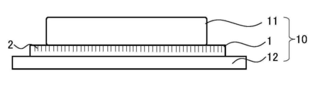
- symbol in FIG. 1 is 1 thermal conductive sheet; 2 cut; 3 thickness; 4 depth of cut; 5 interval of cut; 10 electronic member; 11 heat generating member; 12 cooling member.
- the X direction is also referred to as the left-right direction
- the Y direction is also referred to as the front-rear direction
- the Z direction is also referred to as the up-down direction.
- the heat conductive sheet of the present invention (hereinafter also referred to as “the sheet of the present invention”) has a plurality of cuts on the surface of one or both sheets.
- the sheet of the present invention it is preferable to provide a plurality of cuts in the sheet containing the silicone resin composition and the inorganic filler.
- the sheet of the present invention has high thermal conductivity, high flexibility, and high followability.
- the sheet of the present invention when the sheet of the present invention is sandwiched and adhered between the heat generating member and the cooling member, the sheet of the present invention has the effect of releasing the repulsive force (force in the compression direction) generated vertically by the slit shape by slit processing.
- the sheet of the present invention has high followability to the member, it is difficult to apply an excessive load to the member, so that damage to the member can be reduced, and even when the member has a concave portion or a convex portion, it follows. And high adhesion.
- seat of this invention has high adhesiveness, heat dissipation is also favorable.
- the heat conductive sheet of the present invention is preferably used as a non-adhesive sheet that is sandwiched between a heat generating member and a cooling member and applies a load.
- a plurality of cuts are provided on the surface of one or both of the thermally conductive sheets of the present invention.
- the surface on which the notch is provided may be at least one of the sheet surfaces that are in contact with the member (hereinafter also referred to as the sheet surface).
- the sheet surface may be at least one of the sheet surfaces that are in contact with the member (hereinafter also referred to as the sheet surface).
- a surface is generated in the cut portion by this cutting, it is preferable that at least a part of the surfaces generated by the cutting are in contact with each other.
- This cut is not particularly limited, and may be any of linear, perforated, polygonal, elliptical, circular, and the like.
- linear shape For example, linear shape, meandering shape, a wave shape etc. are mentioned.
- the wave shape is a waveform shape, and examples thereof include a sine wave, a sawtooth wave, a rectangular wave, a trapezoidal wave, and a triangular wave.
- the perforated shape refers to a repetitive shape with and without a cut, such as a broken line.
- polygonal shape For example, triangle shape, quadrangle shape, pentagon shape, hexagon shape, star shape, etc. are mentioned.
- quadrangular shape examples include a trapezoidal shape, a lattice shape (for example, a rectangular shape, a square shape, etc.), a rhombus shape, and a parallelogram shape.
- linear, corrugated, diamond-shaped, circular, star-shaped and lattice-shaped are preferable, more preferably linear-shaped, diamond-shaped and lattice-shaped, and more preferably workability at the time of cutting. And from the point of high followability, it is a lattice shape (especially square shape).
- one or two or more kinds of cuts in the front-rear direction and / or the left-right direction from a straight line, a meandering shape, a wavy shape, a perforated shape, and the like on the sheet surface.
- a straight line a meandering shape, a wavy shape, a perforated shape, and the like
- one section that can be formed into a sheet surface by the cutting can be formed into a quadrangular shape (preferably a lattice shape).
- the cuts can be straight and then perforated.
- the length of one side of the polygonal shape is not particularly limited, but is preferably 0.7 mm to 5 mm, more preferably 0.7 mm to 2.5 mm, and still more preferably 1.0 mm to 2.0 mm when the sheet side is 15 mm. is there.
- “the length of one side of the polygonal shape” can be set to “the length of the diameter”, and in the case of an elliptical shape, the “length of one side of the polygonal shape” is set to “(major axis + The length of the minor axis) / 2.
- the incision according to the present invention is a sheet surface that comes into contact with a member by moving the cutting means as appropriate in any of the vertical direction (Z direction), the front-rear direction (Y direction), the left-right direction (X direction), or a combination thereof.
- a plurality of cuts can be provided in the.
- the cutting means can cut in any direction such as “oblique direction” or “wavy”. With this cutting means, it is possible to perform cutting that is virtually not a groove, and a slit is formed by this cutting, but this slit is such that a streak of cut traces can be seen.
- the width of the slit (the trace on the line where the cut surface can be confirmed (the gap between the cut portions)) is preferably 300 ⁇ m or less, preferably 2 ⁇ m or more and less than 300 ⁇ m, more preferably 100 ⁇ m or less,
- the thickness is preferably 50 ⁇ m or less, and more preferably 2 to 50 ⁇ m.
- the narrower the gap between the cut portions the more advantageous it is that air can hardly enter the sheet surface and a low thermal resistance value can be obtained, and flexibility and followability can be easily obtained.
- the cutting means may be any means that can achieve the condition of the gap between the cut portions, and examples thereof include a cutting blade, a laser irradiation unit, and an irradiation unit capable of water jet (water cutter). Of these, a cutting blade is preferable because the slit can be easily narrowed and processed easily.
- the incision blade may be pushed in from above and / or downward, and the incision may be provided while moving the incision blade in the front-rear direction and / or the left-right direction. May be.
- a cutting die corresponding to the shape may be used, and the cutting may be provided by pushing the cutting die from above and / or downward.
- the cut may be provided while moving the irradiation unit in the front-rear direction and / or the left-right direction.
- the vertical cross-sectional shape of the notch of the present invention is not particularly limited, but for example, a V-shape, a Y-shape, an l-shape (English lowercase letter L), and an oblique l-shape (alphabetic lower-case letter L) arbitrarily angled with an l-shape.
- 2 can refer to the notation 2 of the notch of the heat conductive sheet 1 in FIG. 2, and the slant l-letter (alphabet letter L) with an arbitrary angle in the l shape is the heat conduction in FIG.
- Reference numeral 2b of the cut of the adhesive sheet 1b can be referred to.
- l-shape English lower-case letter L
- the notch is preferably not penetrated.
- the length of the non-penetrating portion (length of the non-cut portion in the vertical direction after cutting) (mm) is preferably 0.1 mm to 6.0 mm, more preferably 0.15 mm to 5.0 mm, and still more preferably 0
- the thickness is from 2 mm to 4.0 mm, more preferably from 0.25 mm to 3.0 mm.
- the ratio of the depth of cut according to the present invention is preferably 2% to 90%, more preferably 30% to 80%, and even more preferably 40% to 70% of the sheet thickness. Setting the depth ratio of the cut to 2% to 90% is advantageous because high flexibility and high followability can be easily obtained and the thermal resistance value can be reduced.
- the depth ratio of this cut is the total of the ratio of the depth of cut on one side and the ratio of the depth of cut on the other side when the cut is on both sides.
- the thickness of the sheet is not particularly limited, but is preferably 0.3 mm to 10 mm, more preferably 0.5 mm to 5.0 mm, and further preferably 1.0 mm to 4.0 mm. By setting the thickness of the sheet to 1.0 mm to 4.0 mm, it is easy to cut and improve followability, which is advantageous in terms of high thermal conductivity and high flexibility.
- the sheet surface in contact with the member has a plurality of sections generated by cutting. More preferably, it is a plurality of sections generated by cutting in the front-rear direction and / or the left-right direction. Providing a plurality of sections is advantageous because adhesion to a member is increased and high followability is easily obtained.
- the shape of the section is not particularly limited, and examples thereof include the polygonal shape, the circular shape, and the elliptical shape described above. Among these, the lattice shape and the triangular shape are preferable, and the lattice shape (more preferably the square shape) is preferable. ) Is preferred.
- the number of sections (hereinafter, “number of sections” is also referred to as “number of divisions”) is not particularly limited, but at least 4 or more, 9 or more, further 36 or more, particularly 49 or more may be provided. preferable.
- the lower limit of the number of sections is more preferably 36 (/ 15 mm 2 ) or more per sheet area of 15 mm 2 , more preferably 49 (/ 15 mm 2 ) or more, and even more preferably 64 (/ 15 mm). 2 ) or more.
- the upper limit value of the number of sections is not particularly limited, but more preferably, it is preferably 2000 (/ 15 mm 2 ) or less, more preferably 1500 (/ 15 mm 2 ) or less, more preferably per sheet area 15 mm 2. Is 1000 pieces (/ 15 mm 2 ) or less, more preferably 500 pieces (/ 15 mm 2 ) or less.
- the preferable number of sections is 49 (/ 15 mm 2 ) to 500 (/ 15 mm 2 ), and more preferably 64 (/ 15 mm 2 ) to 400 (/ 15 mm 2 ).
- the division area ratio (1 section / 1 sheet area) of the section is preferably 25% or less, more preferably 15% or less, still more preferably 5% or less, and still more preferably 3% or less. Moreover, Preferably it is 0.1% or more. The smaller the divided area ratio of the sections, the higher the adhesion to the member and the easier to obtain high followability, and the lower the thermal resistance value and the higher the thermal conductivity.
- the division area ratio (1 division / 1 sheet area) of this division is calculated by “area of 1 division (mm 2 ) / total area of heat conductive sheet in contact with member (mm 2 )” ⁇ 100. be able to.
- the sheet has an Asker C hardness (no notch) of preferably less than 40, more preferably 35 or less, and even more preferably 30 or less. Further, the lower limit value of Asker C hardness is preferably 5 or more from the viewpoint of facilitating handling when handling sheets.
- the sheet has an Asker C hardness (notched) of preferably 35 or less, and more preferably 30 or less. Further, the lower limit value of Asker C hardness is preferably 5 or more from the viewpoint of facilitating handling when handling sheets.
- the difference in Asker C before and after the cut in the sheet is preferably 2 or more, more preferably 5 or more.
- the followability is further improved by obtaining an effect of improving flexibility in which the difference in Asker C before and after cutting is 2 or more.
- This “difference in Asker C before and after cutting” can be calculated by “(Asker C hardness with notch ⁇ Asker C hardness without notch)”.
- the compressive stress (N) when the compressibility of the sheet of the present invention is 20% is compared with the compressive stress (N) when the compressibility is 20% before cutting. It is preferable to reduce the amount by 5% or more, more preferably 10% or more, and further preferably 15% or more. This is preferably reduced by cutting.
- the improvement of the reduction rate of the compressive stress of the sheet (when the compressibility is 20%) by the slit processing of the present invention is advantageous in that it suppresses an initial rapid increase in compressive stress until reaching the peak load during compression,
- the upper limit of this reduction rate is considered to be 90% or less, and it can be produced as 60% or less, 50% or less, 40% or less, 30% or less, and the like.
- the compression stress (N) when the compression rate of the sheet of the present invention is 50% (also referred to as “compression stress (when compression rate is 50%)”) is compared with the compression stress (N) when compression rate is 50% before cutting. It is preferable to reduce the amount by 5% or more, more preferably 10% or more, and further preferably 15% or more. This is preferably reduced by cutting.
- the improvement of the reduction rate of the compressive stress of the sheet (when the compressibility is 50%) by the slit processing of the present invention is advantageous in that it suppresses the increase in the compressive stress in the latter period until the peak load at the time of compression is reached.
- the upper limit of the rate is considered to be 90% or less, and it can be produced as 60% or less, 50% or less, 40% or less, 30% or less.
- the compression stress reduction rate (when the compression rate is 20%) and the compression stress reduction rate (when the compression rate is 50%) of the sheet of the present invention be 5% or more, respectively.
- This “compression stress reduction rate” can be calculated by “(compression stress without notch ⁇ compression stress with notch) / (compressive stress without notch)” ⁇ 100.
- the contact area (mm 2 ) when the compression ratio of the sheet of the present invention is 5% is preferably 130 mm 2 or more, more preferably 200 mm 2 or more, further preferably 220 mm 2 or more per sheet area 225 mm 2. It is suitable in terms of high flexibility and high followability.
- the heat conductive composition used for the heat conductive sheet of the present invention (hereinafter, also referred to as “heat conductive composition”) is not particularly limited.
- a heat conductive composition containing a resin composition and an inorganic filler is preferable to use.
- seat of this invention is suitable to use the silicone resin composition.
- the component (A) silicone resin composition used in the present invention is not particularly limited, and examples thereof include peroxide crosslinking, condensation reaction crosslinking, addition reaction crosslinking, and curing reaction such as ultraviolet crosslinking, among which addition reaction crosslinking.
- the curing reaction by is preferred.
- the component (A) silicone resin composition preferably includes an addition reaction type, and more preferably includes a one-component reaction type or two-component addition reaction type silicone resin composition.
- the component (A) silicone resin composition comprises component (a1) an organopolysiloxane having a vinyl group at least at the terminal or side chain, and component (a2) two or more H—Si groups at least at the terminal or side chain. It is preferable to use a two-component addition reaction type liquid silicone containing an organopolysiloxane having the following formula. Further, the component (B) inorganic filler preferably contains 40 to 85% by volume. Furthermore, the sheet of the present invention preferably has a thermal conductivity of 0.5 W / mK or more.
- the component (A) silicone resin composition the component (A1) and the component (a2) in the component (A) react with the component (B) to cure and form a silicone rubber.
- the inorganic filler has a high content of 40 to 85% by volume in the heat conductive composition, a highly flexible resin molded body (for example, a sheet) Can be obtained.
- a highly heat-conductive resin molded body for example, a sheet
- the component (A) two-component addition reaction type liquid silicone comprises a component (a1) an organopolysiloxane having a vinyl group at least at the terminal or side chain (hereinafter, also referred to as “organopolysiloxane having a vinyl group”), and a component.
- the component (A) preferably has a viscosity at 25 ° C. of 100 to 2,500 mPa ⁇ s.
- the component (a1) is an organopolysiloxane having a vinyl group at least at the terminal or in the side chain, and may have either a linear structure or a branched structure.
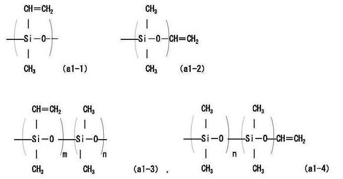
- an organopolysiloxane having a vinyl group is one in which a part of the R portion in the molecule (Si—R) of the organopolysiloxane is a vinyl group (for example, the following general formula (a1-1) ) To (a1-4)).
- the vinyl group content is desirably 0.01 to 15 mol% in (a1), and more preferably 0.01 to 5 mol% in component (a1).
- the organopolysiloxane having a vinyl group as the component (a1) is preferably an alkylpolysiloxane having a vinyl group.
- the alkyl group preferably has 1 to 3 carbon atoms (for example, a methyl group, an ethyl group, etc.), more preferably a methyl group.
- the organopolysiloxane having a vinyl group as the component (a1) preferably has a weight average molecular weight of less than 400,000, more preferably 10,000 to 200,000, still more preferably 15,000 to 200,000.
- the “vinyl group content” in the present invention means the mol% of the vinyl group-containing siloxane unit when the total unit constituting the component (a1) is 100 mol%. However, it is assumed that there is one vinyl group for one vinyl group-containing siloxane unit.
- the component (a2) is an organopolysiloxane having two or more H—Si groups at least at any end or side chain, and may have either a linear structure or a branched structure.
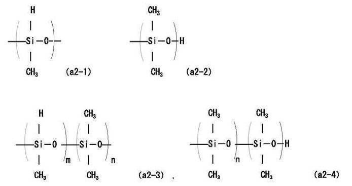
- an organopolysiloxane having an H—Si group is one in which a part of the R portion in the molecule (Si—R) of the organopolysiloxane is an H group (for example, the following general formula (a2 -1) to (a2-4)).
- the H—Si group content is desirably 0.01 to 15 mol% in (a2), and more preferably 0.01 to 5 mol% in component (a2).
- the organopolysiloxane of component (a2) is preferably an alkylpolysiloxane having an H—Si group.
- the alkyl group preferably has 1 to 3 carbon atoms (for example, a methyl group, an ethyl group, etc.), more preferably a methyl group.
- the organopolysiloxane having an H—Si group as component (a2) preferably has a weight average molecular weight of 400,000 or less, more preferably 10,000 to 200,000, and even more preferably 15 , 000 to 200,000.
- the “H—Si group content” in the present invention means the mol% of the H—Si group-containing siloxane unit when the total unit constituting the component (a2) is 100 mol%.
- H—Si group content is measured by NMR. Using ECP-300 NMR manufactured by JEOL, measurement is performed by dissolving the sample in deuterated chloroform as a deuterated solvent. When the content of (vinyl group + H—Si group + Si-methyl group) is 100 mol%, the ratio of H—Si groups contained is the mol% of H—Si groups.
- the component (A) two-component addition reaction type liquid silicone has a viscosity at 25 ° C. of 100 to 2,500 mPa ⁇ s, preferably 100 to 2,000 mPa ⁇ s, more preferably 350 to 2,000 mPa ⁇ s. -S.
- the viscosity (25 ° C.) of the component (A) is 100 mPa ⁇ s or more, the molecular weight is large, so that the cured sheet can be prevented from being easily torn, and if it is 2,500 mPa ⁇ s or less, it is inorganic. This is advantageous in that it is easy to fill with a high amount of filler.
- ⁇ Viscosity measurement> The viscosity of the two-component addition type silicone was measured using a B-type viscometer “RVDVIT” manufactured by BROOKFIELD.
- the spindle uses an f-shaft and can be measured using a viscosity of 20 rpm.
- the component (A) two-component addition reaction type liquid silicone is preferably a thermosetting one among the organopolysiloxanes.
- a curing agent crosslinkable organopolysiloxane
- the base polymer constituting the two-component addition reaction type liquid silicone preferably has an organic group (for example, methyl group, phenyl group, trifluoropropyl group) in the main chain.
- the repeating structure of the organopolysiloxane includes a dimethylsiloxane unit, a phenylmethylsiloxane, a diphenylsiloxane unit, and the like.
- a modified organopolysiloxane having a functional group such as a vinyl group or an epoxy group may be used.
- an addition reaction catalyst for accelerating the addition reaction can be used for the component (A) two-component addition reaction type liquid silicone.
- the said component (A) two-component addition reaction type liquid silicone can use the commercial item which satisfy
- Examples of the terminal or side chain vinyl group of component (a1) include those represented by the following general formula (a1-1) and general formula (a1-2).
- Examples of the organopolysiloxane having a vinyl group at least at the terminal or side chain of component (a1) include those represented by general formula (a1-3) and general formula (a1-4).
- the present invention is not limited to these general formulas (a1-1) to (a1-4).
- the methyl polysiloxane etc. which have a vinyl group in the terminal and / or side chain can be mentioned, for example.
- m and n are preferably positive numbers.
- examples of the terminal or side chain H—Si group of the component (a2) include those represented by the following general formula (a2-1) and general formula (a2-2).
- organopolysiloxane having two or more H—Si groups at least at the terminal or side chain for example, those represented by the following general formulas (a2-3) and (a2-4) Can be mentioned.
- the present invention is not limited to these general formulas (a2-1) to (a2-4).
- Examples of the component (a2) of the present invention include methylpolysiloxane having two or more H—Si groups at the terminal and / or side chain. m and n are preferably positive numbers.
- Examples of commercially available two-component addition reaction type liquid silicone rubbers include “TSE-3062” and “X14-B8530” manufactured by Momentive, “SE-1885A / B” manufactured by Toray Dow Corning, and the like. It is not limited to the range of these specific commercial products.
- the content of the resin composition is preferably 10 to 65% by volume, more preferably 15 to 60% by volume in the entire volume.
- the content of the component (A) two-component addition reaction type liquid silicone is preferably 10 to 65% by volume, more preferably 15 to 60% by volume in the total volume.
- the component (A) content is more preferably 15% by volume or more as a lower limit.
- the content of component (A) is more preferably 65% by volume or less as the upper limit.
- the addition reaction type liquid silicone used in the present invention includes reaction retarders such as acetyl alcohols and maleates, thickeners such as 10 to several hundred ⁇ m aerosil and silicone powder, flame retardants, pigments and the like. It can also be used together.
- the content of the heat conductive filler in the resin composition is preferably 35% by volume or more of the total volume, more preferably 40 to 85% by volume.
- the content of the heat conductive filler is 35% by volume or more, it is easy to avoid the insufficient heat conductivity of the sheet obtained by curing the resin composition.
- liquidity of a resin composition deteriorates that it is 85 volume% or less, and preparation of the hardened
- Examples of the inorganic filler used in the present invention include aluminum oxide, magnesium oxide, boron nitride, aluminum nitride, silicon nitride, silicon carbide, metallic aluminum, and graphite, which are thermally conductive fillers. These can be used alone or in combination of two or more.
- the inorganic filler used in the present invention is preferably spherical (preferably having a sphericity of 0.85 or more). Of these, aluminum oxide is desirable because it exhibits high thermal conductivity and good filling into the resin.
- the aluminum oxide used in the present invention is preferably spherical.
- Aluminum oxide (hereinafter also referred to as “alumina”) may be any of flame spraying method of aluminum hydroxide powder, Bayer method, ammonium alum pyrolysis method, organoaluminum hydrolysis method, aluminum underwater discharge method, freeze drying method, etc. Although it may be produced by a method, a flame spraying method of aluminum hydroxide powder is suitable from the viewpoint of particle size distribution control and particle shape control.
- the crystal structure of the spherical alumina powder may be either a single crystal or a polycrystal, but from the viewpoint of high thermal conductivity, the crystal phase is preferably an ⁇ phase and the specific gravity is preferably 3.7 or more.
- the particle size of the spherical alumina powder can be adjusted by classifying and mixing the spherical alumina powder. When spherical alumina powder is used, the sphericity is 0.85 or more. If the sphericity is less than 0.85, the fluidity is lowered, and the filler is segregated in the spacer, resulting in a large variation in physical properties.
- Examples of commercially available products having a sphericity of 0.85 or more include spherical alumina DAW45S (trade name), spherical alumina DAW05 (trade name), and spherical alumina ASFP20 (trade name) manufactured by Denka Corporation.
- the particle size distribution of the inorganic filler of the present invention preferably has a maximum value or a peak value in the range of an average particle size of 10 to 100 ⁇ m, 1 to 10 ⁇ m and less than 1 ⁇ m.
- the inorganic filler having an average particle diameter of 10 to 100 ⁇ m is preferably 15% by volume or more, more preferably 20 to 50% by volume in the total volume.
- the inorganic filler having an average particle diameter of 1 to 10 ⁇ m is preferably 10 to 30% by volume, more preferably 12 to 30% by volume in the total volume.
- the inorganic filler having an average particle size of less than 1.0 ⁇ m is preferably 5 to 20% by volume, more preferably 8 to 15% by volume in the total volume.
- the said heat conductive sheet can be obtained with a well-known manufacturing method. For example, it can be obtained by mixing the components (A) and (B). Moreover, the heat conductive sheet of this invention is manufactured through the mixing, shaping
- a mixer such as a roll mill, a kneader, or a Banbury mixer is used.
- a doctor blade method is preferable as the molding method, but an extrusion method, a press method, a calender roll method, or the like can be used depending on the viscosity of the resin.
- the vulcanization temperature is desirably 50 to 200 ° C., and the heat curing time is preferably 2 to 14 hours. If it is 50 ° C. or higher, vulcanization is sufficient, and if it is 200 ° C. or lower, it is advantageous in that the deterioration of a part of the spacer can be reduced. Vulcanization is performed using a general hot air dryer, far-infrared dryer, microwave dryer or the like. In this way, a heat conductive sheet can be obtained.
- a resin raw material used in the present invention a resin raw material such as an acrylic resin and an epoxy resin may be appropriately selected and used in addition to the components (A) and (B) as long as the effects of the present invention are not impaired. Good. Moreover, you may mix
- the thickness of the heat conductive sheet (before cutting) of the present invention obtained from the resin composition is desirably 0.3 mm to 10 mm. If the thickness of the heat conductive sheet of the present invention (before cutting) is less than 0.3 mm, the surface roughness due to the heat conductive filler tends to increase and the thermal conductivity tends to decrease. It is desirable to do. On the other hand, if it exceeds 10 mm, the cured product of the resin molded product becomes thick and the thermal conductivity tends to decrease, so 10 mm or less is desirable.
- the thickness of the heat conductive sheet (before cutting) of the present invention is preferably based on the thickness after curing of the resin composition.
- the thermal conductive sheet (before cutting) has high thermal conductivity, and can provide a thermal conductivity of 0.5 W / mK or more.
- the heat conductive sheet of the present invention is characterized in that the surface of the heat conductive sheet having high heat conductivity and high flexibility (before cutting) is cut and the sheet surface is cut.
- the cutting rate is preferably processed in the range of 2% to 90% of the sheet thickness. It is preferable that the effect of reducing the compressive stress (when the compression rate is 20%) when the cut is made is 5% or more as compared with the case where the surface is not cut.
- Conventional heat conductive sheets have a substantially Asker C hardness of up to about 40.
- the stress when compressed is significantly increased, there is a concern that a large stress is applied to the heating element and the substrate on which the heating element is mounted.
- it is important to reduce the compressive stress so that a larger load is not applied when mounting than the Asker C hardness. That is, by using the heat conductive composition, it is possible to produce a heat conductive sheet (before cutting) that has a soft hardness and a high thermal conductivity of 0.5 W / mK or more.
- a heat conductive sheet (after cutting) that can reduce the compressive stress when a plurality of cuts are provided on the sheet surface by 5% or more than when there is no cut is manufactured. be able to.
- the thermal conductive composition it is possible to manufacture a thermal conductive sheet (after being cut) that has high followability to a member when a plurality of cuts are made.
- the heat conductive composition since it has a high flexibility in the range of 5 to 40 in Asker C hardness, a heat conductive sheet (before cutting) that can particularly reduce compressive stress is manufactured. can do.
- the heat conductive sheet (before cutting) obtained using the heat conductive composition is a sheet suitable as a sheet before processing of the heat conductive sheet provided with a plurality of cuts of the present invention.
- the method for producing a thermally conductive sheet having a plurality of cuts according to the present invention is characterized by performing a plurality of cuts as described above, and the thermal conductivity before cutting outside the range of the Asker C hardness. This is a manufacturing method that may find the same effect with respect to a sheet (for example, a heat dissipation material).
- the heat conductive sheet 1 of the present embodiment is provided with a plurality of cuts 2 by being cut in the left and right directions and the front and rear directions so as to form a lattice on the sheet surface in contact with the members. ing.
- the thermal conductive sheet 1 of the present embodiment is provided with a cut 2 in the vertical direction to a cut depth of 4.
- the cut depth 4 does not reach the sheet thickness 3, and the vertical cut 2 is not penetrated.
- at least part of the surfaces in the vertical direction generated by the left and right and front and rear cuts 2 are in contact with each other.
- the vertical cross-sectional shape of the notch 2 is an l-shape (lowercase letter L).
- the heat conductive sheet 1 of this embodiment has the some division 6 formed by the cutting process of the left-right direction and the front-back direction, and this division 6 is a grid
- One side of this section 6 is the interval 5 between the notches 2 adjacent in the left-right direction and the interval 5 between the notches 2 adjacent in the front-rear direction.
- the heat conductive sheet 1 of this embodiment is obtained by slitting a heat conductive sheet formed from a composition containing a silicone resin composition and an inorganic filler with a cutter.
- the heat conductive sheet 1 of this embodiment is used for an electronic member 10.
- the electronic member 10 of the present embodiment includes the heat conductive sheet 1 of the present embodiment, a heat generating member 11 including a semiconductor element that generates heat, and a cooling member 12 such as a heat radiating fin.
- the heat conductive sheet 1 of this embodiment is sandwiched between the heat generating member 11 and the cooling member 12 with a load applied.
- the sheet surface having a plurality of cuts of the heat conductive sheet 1 of the present embodiment is in contact with the heat generating member 11. Since the heat conductive sheet 1 of the present embodiment has high flexibility and a cut structure, it has high followability corresponding to the ground contact surface of the heat generating member 11.
- the heat conductive sheet 1 of the present embodiment is in contact without damaging these members due to high followability and high flexibility. And since the heat conductive sheet 1 of this embodiment has high heat conductivity, and high flexibility and high followability, it can transmit heat generated from the heat generating member 11 to the cooling member 12 efficiently. The heat from the member 11 is efficiently radiated.
- the electronic member 10 provided with the heat conductive sheet 1 of the present embodiment can be provided as an electronic component that can reduce the lifetime reduction, malfunction, and failure of the electronic component due to temperature rise, housing distortion, and the like.
- the heat conductive sheet 1b as shown in FIG. 3 may be sufficient as the heat conductive sheet of this invention, and the electronic member 10b provided with the heat conductive sheet 1b may be sufficient as the electronic member of this invention.
- the heat conductive sheet 1b according to the present embodiment has a plurality of slant l-letters (English lower-case letter L) with an angle formed on the surface thereof as a cut 2b. And since the heat conductive sheet 1b of this embodiment has high heat conductivity, and has high flexibility and high followability, heat generated from the heat generating member 11 can be efficiently transmitted to the cooling member 12, and heat generated. The heat from the member 11 is efficiently radiated.
- the electronic member 10b including the heat conductive sheet 1b of the present embodiment can be provided as an electronic component that can reduce the lifetime reduction, malfunction, and failure of the electronic component due to temperature rise, housing distortion, and the like.
- the vertical cross-sectional shape of the cut is “an oblique l-shape inclined to the left” in which a cut is made obliquely from the left direction on the surface of the heat conductive sheet, but the direction of the cut is There is no particular limitation, and an angle may be cut from the right direction, and an oblique cut may be made from the left direction.
- the vertical cross-sectional shape of the cut may be a heat conductive sheet in which “an oblique l-shape inclined to the left” and “an oblique l-shape inclined to the right” are mixed.
- thermo conductive sheet having high thermal conductivity and high flexibility and further having high followability to members.
- the heat conductive sheet of this invention provides not only a groove
- an electronic component that generates heat such as a heat radiating member and a heat radiating component, an electronic member, and an electronic component, and related products, including the heat conductive sheet of the present invention.
- a heat conductive heat radiating sheet having high thermal conductivity and high flexibility, and further having high followability.
- a heat dissipation spacer can be preferably provided, and the heat dissipation spacer is particularly suitable as a heat dissipation member for electronic components.
- the heat conductive sheet of the present invention is preferably used as a heat radiating member for electronic parts that requires close adhesion between the heat generating surface of the semiconductor element and the heat radiating surface such as a heat radiating fin.
- the heat dissipating member of the present invention is desirably used as a heat dissipating sheet, a heat dissipating spacer or the like.
- the heat conductive sheet and the heat radiating member of the present invention are highly flexible and have excellent adhesion to the heat generating elements, electronic devices (for example, smartphones, tablet PCs, personal computers, consumer game machines, power supplies, automobiles) Etc.), and for example, can be applied to wireless base station applications.
- the spacer of the present invention is manufactured through a raw material mixing / molding / vulcanizing process.
- a mixer such as a roll mill, a kneader, or a Banbury mixer is used.
- the molding method is preferably a doctor blade method, but depending on the viscosity of the thermally conductive composition, an extrusion method, a press method, a calender roll method, or the like can be used.
- the vulcanization temperature is preferably 50 to 200 ° C. If it is less than 50 ° C., vulcanization is insufficient, and if it exceeds 200 ° C., a part of the spacer deteriorates.
- Vulcanization is performed using a general hot air dryer, far-infrared dryer, microwave dryer or the like. In this way, a heat conductive sheet is obtained.
- the cutting method may be any method regardless of slitting with a cutter or laser scalpel, and it is possible to cut 2 to 90% of the thickness.
- the present invention is suitably used for a heat conductive member such as an industrial member, and is particularly suitable for a highly flexible and high heat conductive sheet and a heat radiating member having a small compressive stress during mounting. Even if the heat conductive sheet of this invention has a notch
- Two-component addition-reactive silicone containing component (A) (a1: organopolysiloxane having a vinyl group) + (a2: organopolysiloxane having an H—Si group) shown below, and (B) an inorganic filler Were mixed based on the blending ratio and volume% ratio of each test example described in Tables 1 to 4.
- the total amount of component (A) and component (B) was 100% by volume.
- a sheet (resin molded body) having a predetermined thickness was prepared using a doctor blade (method) using the mixed composition, and heat-cured at 110 ° C. for 8 hours. As a result, various heat conductive sheets of Test Examples 1 to 45 were produced.
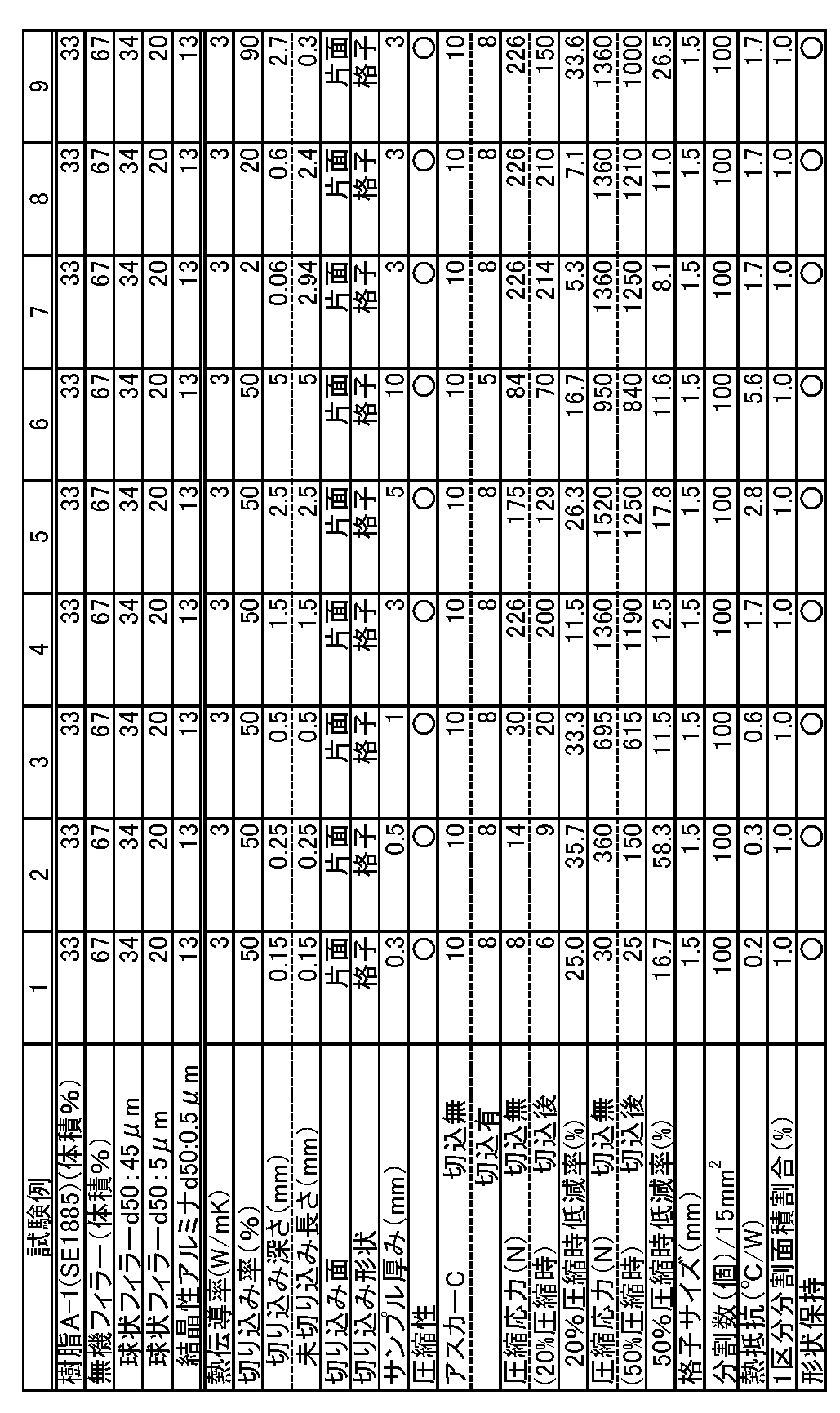
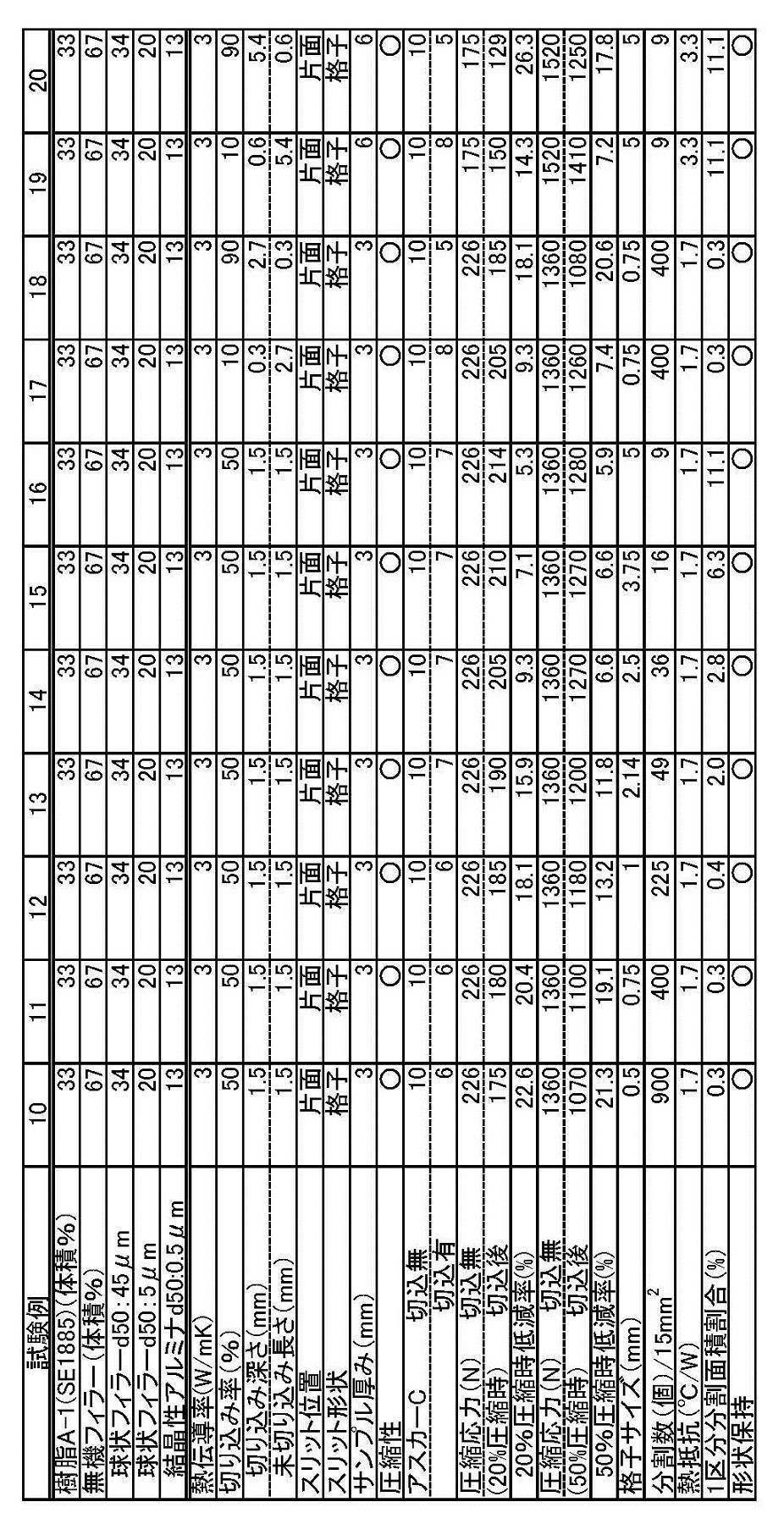
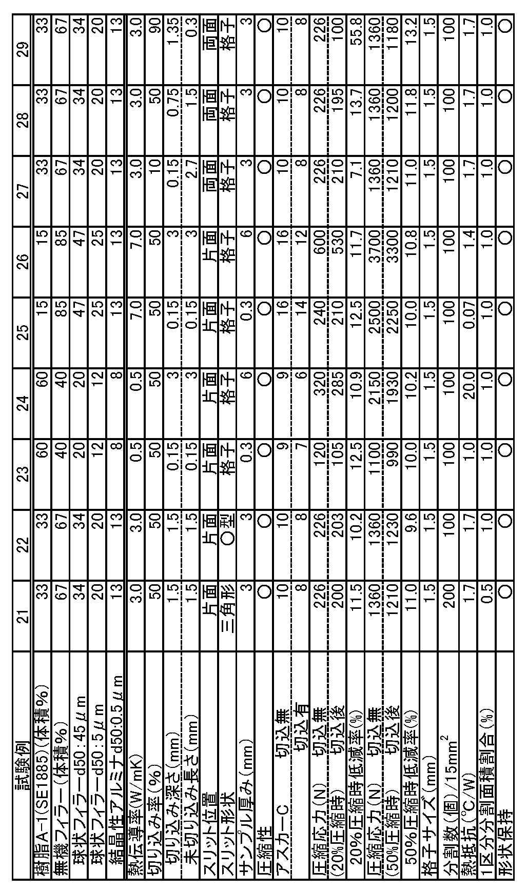
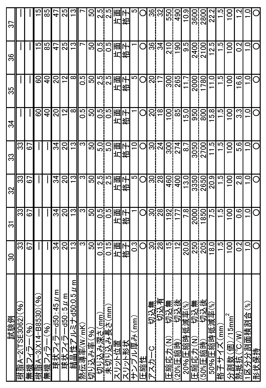
- Tables 1 to 4 show the compositions, cutting conditions, and evaluation results of Test Examples 1 to 37.
- a cutting blade When making it into a grid by cutting, a cutting blade was used to make a linear cut in the front-rear direction and the left-right direction in the thermally conductive sheet. This cutting process generates a plurality of sections, and the shape of one section is a lattice shape.
- a cutting blade In the case of forming a triangle (isosceles triangle 2 sides 1.5 mm) by cutting, a cutting blade was used to make a straight cut with reference to the diagonal line of the sheet. A plurality of sections are generated by this cutting process, and the shape of one section is a diamond shape.
- Test Examples 1 to 6, Test Examples 7 to 9, Test Examples 17 to 20, and Test Examples 23 to 26, the surface of the sheet obtained using the composition containing components (A) and (B) is cut.
- a heat conductive heat radiating sheet having a flexibility capable of reducing the compressive stress by 5% or more than when no notch was formed could be obtained.
- the cutting rate was 2 to 90%, a heat conductive heat radiating sheet having a compressive stress reducing effect could be obtained.
- Test Examples 1 to 37 even when the slit shape was provided, the shape retention in these heat radiating sheets was good (good).
- the surface of the sheet obtained using the composition containing components (A) and (B) has various shapes such as a lattice shape, a triangular shape, and a (circle) shape.
- a heat conductive heat dissipating sheet having the flexibility to reduce the compressive stress by 5% or more than when not making the cuts.
- a heat-conductive heat-dissipating sheet that has the flexibility to reduce the compressive stress by 5% or more by notching regardless of one or both sides of the sheet, compared to when not notching could get.
- Test Examples 30 to 37 were obtained using compositions containing component (A) and component (B) regardless of the molecular weight of the silicone resin of components (A) and (B) and the amount of thermally conductive filler. By making a cut on the sheet surface, a heat conductive heat dissipating sheet having the flexibility to reduce the compressive stress by 5% or more than when not making a cut could be obtained.
- the raw materials used for the production of the thermally conductive composition are as follows.
- Component (B) Inorganic filler The following aluminum oxide was used as the inorganic filler.
- the volume% of inorganic filler in the table is the total amount of each spherical filler and each crystalline alumina used.
- Filler d50 45 ⁇ m: Spherical alumina DAW45S manufactured by DENKA CORPORATION
- Filler d50 5 ⁇ m: Spherical alumina DAW05 manufactured by DENKA CORPORATION
- d50 0.5 ⁇ m: crystalline alumina AA-05 manufactured by Sumitomo Chemical Co., Ltd.
- the thermal conductive sheet obtained above was cut into a TO-3 type and the thermal resistance was measured.
- the thermal resistance is sandwiched between a TO-3 type copper heater case (effective area 6.0 cm 2 ) with a built-in transistor and a copper plate, and 10% of the initial thickness is compressed.
- thermal conductivity (W / mK) thickness (m) / (cross-sectional area (m 2) ⁇ thermal resistance (°C / W)) ⁇ ( 2) " I can do it.
- the hardness of the heat conductive sheet used for this invention can be measured with the Asker C type spring type hardness tester based on SRIS0101 of 25 degreeC.
- the Asker C hardness can be measured by “Asker Rubber Hardness Tester C type” manufactured by Kobunshi Keiki Co., Ltd.
- the type C Asker C hardness of the silicone resin after curing was 5 to less than 40. When the type C hardness is 5 or more, handling when handling the sheet is easy.
- the weight average molecular weights of the polyorganosiloxane and the silicone were values in terms of polystyrene determined from the results of gel permeation chromatography analysis. Separation was performed using a non-aqueous porous gel (polystyrene-dimethylbenzene copolymer), toluene was used as the mobile phase, and a differential refractometer (RI) was used for detection.
- RI differential refractometer
- ⁇ Average particle size, maximum particle size, maximum value> The average particle size, maximum particle size, and maximum value of the inorganic filler were measured using “Laser Diffraction Particle Size Distribution Analyzer SALD-20” manufactured by Shimadzu Corporation.
- SALD-20 “Laser Diffraction Particle Size Distribution Analyzer SALD-20” manufactured by Shimadzu Corporation.
- 5 g of 50 cc of pure water and an inorganic filler powder to be measured were added to a glass beaker, stirred using a spatula, and then subjected to dispersion treatment for 10 minutes with an ultrasonic cleaner.
- the solution of the inorganic filler powder that had been subjected to the dispersion treatment was added drop by drop to the sampler portion of the apparatus using a dropper, and waited until the absorbance became measurable.
- the measurement is performed when the absorbance becomes stable in this way.
- the particle size distribution is calculated from the data of the light intensity distribution of the diffracted / scattered light by the particles detected by the sensor.
- the average particle size is obtained by multiplying the value of the measured particle size by the relative particle amount (difference%) and dividing by the total relative particle amount (100%).
- the average particle diameter is the average diameter of the particles, and the maximum value can be obtained as the particle diameter (mode diameter) corresponding to the mode value of the particle size distribution.
- the maximum value of the particle diameter from the obtained particle size distribution can be obtained as the maximum particle diameter.
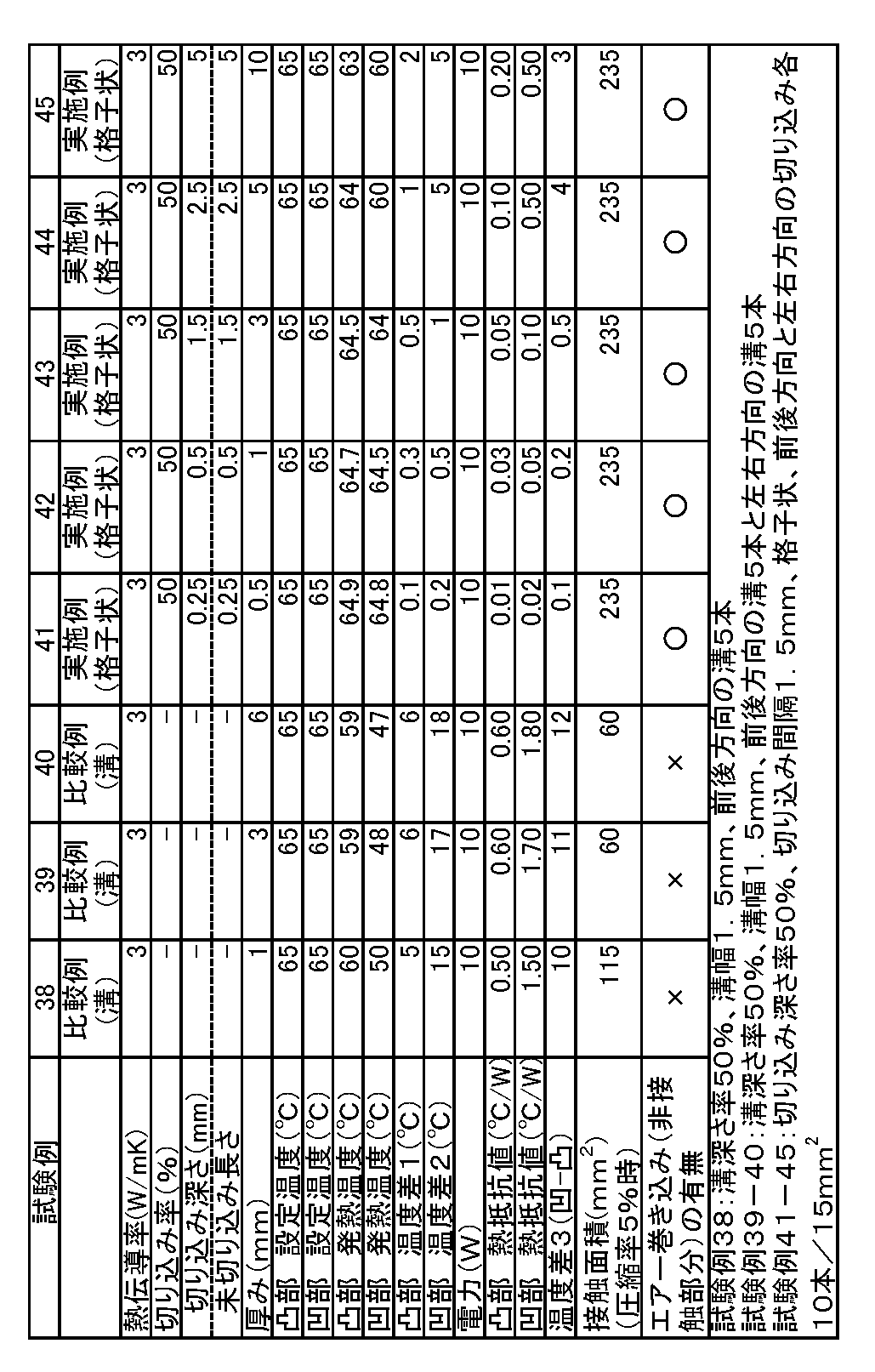
- Table 5 shows the processing conditions and evaluation results of Test Examples 38 to 45.
- the temperature was measured using HP-1SA manufactured by ASONE as the heating device and FLIRi5 manufactured by CHINO as the temperature measuring device.
- the heat conductive sheet to be used was obtained by using the composition used in Test Example 1 and referring to the sheet manufacturing method of Test Example 1 to obtain a heat conductive sheet having various thicknesses and not being cut. .
- Slit processing was performed on one side of the uncut sheet to obtain thermally conductive heat dissipation spacers of Test Examples 41 to 45 (Examples).
- the depth ratio of the incision was 50%, the interval between the incisions was 1.5 mm, and the sections generated by the incisions were in a lattice shape.
- a groove (1.5 mm) was processed on one side of the uncut sheet to obtain heat conductive sheets of Test Examples 38 to 40.
- the depth ratio of the groove was 50%.
- ⁇ Convex test / concave test> A convex portion and a concave portion were simulated on the surface of one heating element, and a convex portion test and a concave portion test were performed on one surface.
- the convex part test the case where a copper jig assembled so as to have a compression ratio of 30% with respect to the thickness of the heat conductive sheet was sandwiched was defined as a convex part of the heating element.
- a heat conductive sheet was sandwiched between the heating element and the resin plate, and a copper jig assembled so as to have a compression ratio of 5% with respect to the thickness of the heat dissipation spacer was clamped. Recessed. Thereby, the electronic member for a convex part / recessed part test was produced. The produced convex / concave test electronic member was placed on a hot plate, and the hot plate was heated to heat the copper jig to 65 ° C.
- the temperature 5 minutes after the heating of the heat conductive sheet was measured at a temperature within 5 mm ⁇ (diameter) near the center of a 15 mm ⁇ (diameter) cylinder. The measurement was performed 5 minutes after setting the sheet on the jig.
- the convex portion temperature difference 1 (° C.) and the concave portion temperature difference 2 (° C.) are values calculated by setting temperature ⁇ heating temperature.
- the temperature difference 3 (concave-convex) (° C.) is a value calculated by the concave portion temperature difference 2 ⁇ the convex portion temperature difference 1.
- the “convex thermal resistance value (° C./W)” and “concave thermal resistance value (° C./W)” are calculated by calculating the temperature difference with respect to the electric power (W) of the heater. did.
- Test examples 38, 39, and 40 as comparative products were heat-conductive sheets that were grooved, and test examples 41 to 45 as actual products were slit-processed heat-conductive sheets.
- test examples 38 to 40 even if the number of grooves is changed, the temperature difference concave-convex is 10 ° C. or more, and depending on the compression ratio, the thermal conductivity is deteriorated, whereas in Test Examples 41 to 45, the effect of the slit shape causes The temperature difference concave-convex was 5 ° C. or less, and an excellent heat conductive sheet could be obtained.
- Test Examples 38 to 40 it was confirmed that the contact area of the recess with a compression ratio of 5% was 120 mm 2 or less, and the air with low thermal conductivity was interposed in the part where the contact area was small and not closely attached.
- Test Examples 41 to 45 it was confirmed that the contact area of the recesses was 220 mm 2 or more and adhered in a wide range, and no air was observed.
Landscapes
- Chemical & Material Sciences (AREA)
- Engineering & Computer Science (AREA)
- Organic Chemistry (AREA)
- Chemical Kinetics & Catalysis (AREA)
- Physics & Mathematics (AREA)
- Thermal Sciences (AREA)
- Microelectronics & Electronic Packaging (AREA)
- Materials Engineering (AREA)
- Combustion & Propulsion (AREA)
- Health & Medical Sciences (AREA)
- Medicinal Chemistry (AREA)
- Polymers & Plastics (AREA)
- Cooling Or The Like Of Semiconductors Or Solid State Devices (AREA)
- Compositions Of Macromolecular Compounds (AREA)
- Cooling Or The Like Of Electrical Apparatus (AREA)
- Manufacture Of Macromolecular Shaped Articles (AREA)
Abstract
Description
さらに、高熱伝導性のシートの柔軟性を高めるため無機フィラーの充填率を抑えると、自ずと高熱伝導性のシートの熱抵抗値が上がり必要な放熱性が満足できない懸念がある。
しかしながら、このような溝を多数有する熱伝導性の放熱スペーサーは、発熱部材と放熱部材とに挟み込んで固定した場合、熱がこもる、また発熱部材の凸部及び凹部の温度上昇に関してうまく放熱できず、またこの凸凹部の温度差も大きく、凸部や凹部の熱抵抗値も高かった。
しかしながら、本発明者らは、さらに鋭意検討した結果、部材に接する熱伝導性シートの面に、U字状のような幅のある溝ではなく、切り込みを複数設けることで、無機フィラーを高充填しても高柔軟性を有するとともに、部材への追従性も高くなることで、低熱抵抗値となり放熱も良好であることを見出した。このようにして、本発明者らは、高柔軟性及び高熱伝導性を有すると共に、さらに高追従性を有する高熱伝導性シートを得ることができ、このようなことは全くの予想外のことであり、これにより本発明を完成させた。
また、本発明は、前記熱伝導性シートの製造方法を提供するものである。
前記切り込みは未貫通であってもよい。
前記切り込みの深さの割合は、シート厚みの2%~90%であってもよい。前記切り込みにより生じた複数の区分を有していてもよい。さらに、前記区分は、前後方向及び/又は左右方向の切り込みにより生じたものであってもよい。
前記シートの圧縮応力(圧縮率20%時)が、切り込み前と比較し、少なくとも5%低減されてもよい。
前記シートのアスカーC硬度が、40未満であってもよい。
前記区分の分割面積割合(1区分/1シート面積)が、25%以下であってもよい。また、前記熱伝導性シートの厚みが、0.3~10mmであってもよい。
前記無機フィラーが、40~85体積%であってもよい。
前記シリコーン樹脂組成物が、少なくとも末端又は側鎖にビニル基を有するオルガノポリシロキサンと、少なくとも末端又は側鎖に2個以上のH-Si基を有するオルガノポリシロキサンと、を含む二液付加反応型液状シリコーンであってもよい。
前記シリコーン樹脂組成物が、少なくとも末端又は側鎖にビニル基を有するオルガノポリシロキサンの重量平均分子量が10,000~400,000であり、少なくとも末端又は側鎖に2個以上のH-Si基を有するオルガノポリシロキサンとの重量平均分子量が10,000~400,000であってもよい。
また、前記無機フィラーは、酸化アルミニウム、窒化アルミニウム及び酸化亜鉛から選択される1種以上であってもよい。また、熱伝導率が、0.5W/mK以上であってもよい。
なお、図1中の符号は、1 熱伝導性シート;2 切り込み;3 厚み;4 切り込みの深さ;5 切り込みの間隔;10 電子部材;11 発熱部材;12 冷却部材である。また、X方向は左右方向、Y方向は前後方向、Z方向は上下方向ともいう。
本発明の熱伝導性シート(以下、「本発明のシート」ともいう。)は、一方又は両方のシートの面に複数の切り込みを有するものである。また、本発明のシートは、シリコーン樹脂組成物及び無機フィラーを含むシートに、複数の切り込みを設けるのが好適である。
本発明のシートは、高熱伝導性、高柔軟性及び高追従性を有する。
従来の溝を設けた熱伝導性シートは、部材の間に挟持した場合に、密着面の溝のデッドスポットから排出できない箇所に空気が残り、熱抵抗値が上がる懸念がある。
本発明の熱伝導性シートの一方又は両方のシートの面には、複数の切り込みが設けられている。
切り込みを設ける面は、部材が接するシート面の少なくとも何れか一方(以下、シート表面ということもある)であればよい。また、この切り込みによって切り込み部分に面が生じるが、この切込みによって生じる面同士の少なくとも一部が接触することが好ましい。
この切り込みは、特に限定されず、線状、ミシン目状、多角形状、楕円形状、円形状等の何れでもよい。
多角形状として、特に限定されないが、例えば、三角形状、四角形状、五角形状、六角形状、星型形状等が挙げられる。この四角形状として、例えば、台形形状、格子状(例えば、長方形状、正方形状等)、ひし形状、平行四辺形状等が挙げられる。
前記切り込みのうち、直線状、波状、ひし形状、円形状、星型形状及び格子状が好ましく、より好ましくは、直線状、ひし形状及び格子状であり、さらに好ましくは、切り込み加工時の作業性及び高追従性の点から、格子状(特に正方形状)である。
多角形状の一辺の長さは、特に限定されないが、シート一辺15mmのとき、好ましくは0.7mm~5mm、より好ましくは0.7mm~2.5mm、さらに好ましくは1.0mm~2.0mmである。なお、円形状の場合は、「多角形状の一辺の長さ」を「直径の長さ」とすることができ、楕円形状の場合は、「多角形状の一辺の長さ」を「(長径+短径)/2の長さ」とすることができる。
このカット手段により、事実上溝でない切り込み加工が可能であり、この切り込み加工によりスリットができるが、このスリットはカットの痕跡のスジが見える程度である。また、このスリット(カット面が確認できる程度の線上の痕跡(カット部分の隙間))は、幅が300μm以下であることが好ましく、好ましくは2μm以上300μm未満であり、より好ましくは100μm以下、さらに好ましくは50μm以下であり、よりさらに好ましくは2~50μmである。カット部分の隙間が狭いほど、シート面に空気も入りにくく低い熱抵抗値にすることができ、また柔軟性及び追従性も得やすいので有利である。
前記カット手段として、上記のカット部分の隙間の条件を達成可能な手段であればよく、例えば、切り込み刃、レーザー照射部及びウォータージェット(ウォーターカッター)可能な照射部等が挙げられる。このうち、スリットを狭くしやすく加工容易なため、切りこみ刃が好ましい。
未貫通部分の長さ(切り込み後の上下方向における未切り込み部分の長さ)(mm)は、好ましくは0.1mm~6.0mm、より好ましくは0.15mm~5.0mm、さらに好ましくは0.2mm~4.0mm、よりさらに好ましくは0.25mm~3.0mmである。
本発明の切り込みの深さの割合は、シート厚みの2%~90%が好ましく、30%~80%がより好ましく、さらに40%~70%が好ましい。
切り込みの深さの割合は、2%~90%にすることで、高柔軟性及び高追従性が得やすいとともに、熱抵抗値も低減できるため、有利である。
この切り込みの深さ割合は、切り込みが両面にある場合には、片面の切り込み深さの割合と、もう片面の切り込み深さの割合とを合計した割合となる。
前記シートの厚みは、特に限定されないが、好ましくは0.3mm~10mmであり、より好ましくは0.5mm~5.0mmであり、さらに好ましくは1.0mm~4.0mmである。シートの厚みを、1.0mm~4.0mmにすることで、切りこみ加工して追従性を高めることが容易であり、高熱伝導性及び高柔軟性の点でも有利である。
前記区分の形状は、特に限定されないが、例えば、上述した、多角形状、円形状、楕円形状等が挙げられ、このうち、格子状及び三角形状が好ましく、さらに格子状(より好適には正方形状)が好ましい。
前記区分数の下限値において、より好適には、シート面積15mm2当たり、好ましくは36個(/15mm2)以上、より好ましくは49個(/15mm2)以上、さらに好ましくは64個(/15mm2)以上である。
前記区分数の上限値において、特に限定はないが、より好適には、シート面積15mm2当たり、好ましくは2000個(/15mm2)以下、より好ましくは1500個(/15mm2)以下、さらに好ましくは1000個(/15mm2)以下、よりさらに好ましくは500個(/15mm2)以下である。
また、前記区分の分割面積割合(1区分/1シート面積)は、好ましくは25%以下であり、より好ましくは15%以下、さらに好ましくは5%以下、よりさらに好ましくは3%以下である。また、好ましくは0.1%以上である。
区分の分割面積割合を少なくするほど、部材との密着性が高くなり高追従性が得やすいとともに、熱抵抗値も低減でき、高熱伝導性とすることができるため、有利である。
なお、この区分の分割面積割合(1区分/1シート面積)は、「1区分の面積(mm2)/部材の接する方の熱伝導性シートの全体面積(mm2)」×100で算出することができる。
前記シートのアスカーC硬度(切り込み有り)は、好ましくは35以下であり、より好ましくは30以下である。また、アスカーC硬度の下限値は、シートを取り扱う際のハンドリング性を容易にする点から、5以上が好ましい。
この「切り込み前後のアスカーCの差」は、「(切り込み有り時のアスカーC硬度-切り込みなし時のアスカーC硬度)」にて算出することが出来る。
本発明のスリット加工によるシートの圧縮応力(圧縮率20%時)の低減率の向上は、圧縮時のピーク荷重に到達するまでの初期の急激な圧縮応力の上昇を抑える点で有利であり、この低減率の上限値は90%以下と考えられ、60%以下、50%以下、40%以下、30%以下等と作製可能である。
本発明のスリット加工によるシートの圧縮応力(圧縮率50%時)の低減率の向上は、圧縮時のピーク荷重に到達するまでの後期の圧縮応力の上昇を抑える点で有利であり、この低減率の上限値は90%以下と考えられ、60%以下、50%以下、40%以下、30%以下等と作製可能である。
この「圧縮応力の低減率」は、「(切り込みなし時の圧縮応力-切り込み有り時の圧縮応力)/(切り込みなし時の圧縮応力)」×100にて算出することができる。
本発明の熱伝導性シートに用いる熱伝導性組成物(以下、「熱伝導性組成物」ともいう)は、特に限定されない。
本発明のシートには、樹脂組成物及び無機フィラーを含む熱伝導性組成物を用いることが好適である。さらに、本発明のシートには、成分(A)シリコーン樹脂組成物及び成分(B)無機フィラーを含む熱伝導性組成物を用いることが好適である。シリコーン樹脂組成物を用いることで、高柔軟性及び高熱伝導性の熱伝導性シートを得ることができる。
本発明に用いる成分(A)シリコーン樹脂組成物は、特に限定されず、例えば、過酸化物架橋、縮合反応架橋、付加反応架橋、及び紫外線架橋等による硬化反応が挙げられ、このうち付加反応架橋による硬化反応が好ましい。
さらに、前記成分(B)無機フィラーは40~85体積%を含むものが好適である。
さらに、本発明のシートは、熱伝導率が0.5W/mK以上であることが好適である。
前記成分(A)二液付加反応型液状シリコーンは、成分(a1)少なくとも末端又は側鎖にビニル基を有するオルガノポリシロキサン(以下、「ビニル基を有するオルガノポリシロキサン」ともいう。)と、成分(a2)少なくとも末端又は側鎖に2個以上のH-Si基を有するオルガノポリシロキサン(以下、「H-Si基を有するオルガノポリシロキサン」ともいう。)と、を含むものである。前記成分(A)は、25℃での粘度が100~2,500mPa・sであることが望ましい。
このビニル基含有量は、(a1)中に、0.01~15モル%であることが望ましく、また成分(a1)中に、0.01~5モル%であることがより好ましい。
前記成分(a1)のビニル基を有するオルガノポリシロキサンは、ビニル基を有するアルキルポリシロキサンが好適である。このアルキル基は、炭素数1~3(例えば、メチル基、エチル基等)が好ましく、より好ましくはメチル基である。
ここで、本発明における「ビニル基の含有量」とは、成分(a1)を構成する全ユニットを100モル%としたときのビニル基含有シロキサンユニットのモル%のことをいう。ただし、ビニル基含有シロキサンユニット1つに対して、ビニル基1つであるとする。
<ビニル基含有量測定方法>
NMRによりビニル基含有量を測定する。具体的には、JEOL社製 ECP-300NMRを使用し、サンプルを重溶媒として重クロロホルムに溶解して測定する。(ビニル基+H-Si基+Si-メチル基)を100モル%とした場合のビニル基の割合をビニル基含有量モル%とする。
このH-Si基含有量は、(a2)中に、0.01~15モル%であることが望ましく、また成分(a2)中に、0.01~5モル%であることがより好ましい。
前記成分(a2)のオルガノポリシロキサンは、H-Si基を有するアルキルポリシロキサンが好適である。このアルキル基は、炭素数1~3(例えば、メチル基、エチル基等)が好ましく、より好ましくはメチル基である。
ここで、本発明における「H-Si基の含有量」とは、成分(a2)を構成する全ユニットを100モル%としたときのH-Si基含有シロキサンユニットのモル%のことをいう。
(a1)と(a2)の含有比は、質量比で、(a1):(a2)=20~80:20~80が好ましく、40~60:40~60がより好ましく、(a1):(a2)=50:50が最も好ましい。
<H-Si基含有量測定方法>
NMRによりH-Si基含有量を測定する。JEOL社製 ECP-300NMRを使用し、サンプルを重溶媒として重クロロホルムに溶解して測定する。(ビニル基+H-Si基+Si-メチル基)を100モル%とした場合に含有するH-Si基の割合をH-Si基の含有量モル%とする。
前記成分(A)の粘度(25℃)が100mPa・s以上であると分子量が大きいため、硬化後のシートが裂けやすくなることを回避することができ、2,500mPa・s以下であると無機フィラーを高充填することがしやすくなる点で有利である。
<粘度測定>
二液付加型シリコーンの粘度についてはBROOKFIELD社製B型粘度計「RVDVIT」を用いて測定した。スピンドルはfシャフトを使用し、20rpmの粘度を用いて測定することができる。
前記二液付加反応型液状シリコーンを構成するベースポリマーは、その主鎖に有機基(例えば、メチル基、フェニル基、トリフルオロプロピル基等)を持つものが好ましい。例えば、オルガノポリシロキサンの繰り返し構造は、ジメチルシロキサンユニット、フェニルメチルシロキサン、ジフェニルシロキサンユニット等が挙げられる。また、ビニル基、エポキシ基等の官能基を有する変性オルガノポリシロキサンを用いてもよい。
また、前記成分(A)二液付加反応型液状シリコーンには、付加反応を促進させるための付加反応触媒を用いることができる。
また、前記成分(A)二液付加反応型液状シリコーンは、上記各種条件を満たす市販品を使用できる。
また、前記成分(A)二液付加反応型液状シリコーンの含有量は、全体積中、好適には10~65体積%であり、より好適には15~60体積%である。成分(A)含有量は、下限値としてより好ましくは15体積%以上である。また、成分(A)の含有量は、上限値として、より好ましくは65体積%以下である。
前記成分(A)の含有量は、前記熱伝導性組成物中10体積%以上であると柔軟性を高くすることができ、前記熱伝導性組成物中65体積%以下であると熱伝導率の低下を回避しやすい点で有利である。
前記樹脂組成物における熱伝導性フィラーの含有率は、好ましくは全体積中の35体積%以上であり、より好ましくは40~85体積%であることが望ましい。
熱伝導性フィラーの含有率が35体積%以上では樹脂組成物を硬化したシートの熱伝導性が不十分となるのを回避しやすいので、含有量が高いほど望ましい。また、85体積%以下であると、樹脂組成物の流動性が悪くなるのを回避しやすく、0.3mm以上の厚さで樹脂組成物の硬化物の作製がしやすい。
これらのうち、酸化アルミニウムは、高熱伝導性を示すとともに、樹脂への充填性が良好なため、望ましい。
また、球状アルミナ粉末の結晶構造は、単結晶体、多結晶体の何れでもよいが、高熱伝導性の点から結晶相はα相が望ましく、また比重は3.7以上が望ましい。比重が3.7未満であると粒子内部に存在する空孔と低結晶相の存在割合が多くなるため、熱伝導率を2.5W/mK以上に高める場合には3.7以上が望ましい。球状アルミナ粉末の粒度調整は、球状アルミナ粉末の分級・混合操作によって行うことができる。
球状アルミナ粉末を使用する場合は、球形度が0.85以上である。球形度が0.85未満では流動性が低下してスペーサー内でフィラーが偏析してしまい物性のばらつきが大きくなる。球形度が0.85以上である市販品として、例えば、デンカ株式会社製の球状アルミナDAW45S(商品名)、球状アルミナDAW05(商品名)、球状アルミナASFP20(商品名)等が挙げられる。
前記平均粒子径10~100μmの無機フィラーが、全体積中、好ましくは15体積%以上、より好ましくは20~50体積%である。
また、前記平均粒子径1~10μmの無機フィラーが、全体積中、好ましくは10~30体積%、より好ましくは12~30体積%である。
また、前記平均粒子径1.0μm未満の無機フィラーが、全体積中、好ましくは5~20体積%、より好ましくは8~15体積%である。
前記無機フィラーの粒度分布は、これら3つの範囲の無機フィラーを適宜組み合わせることが好ましい。
前記熱伝導性シートは、公知の製造方法にて得ることができる。例えば、前記成分(A)及び(B)を混合することで得ることができる。
また、本発明の熱伝導性シートは、例えば、原料の混合・成形・加硫工程を経て製造される。混合には、ロールミル、ニーダー、バンバリーミキサー等の混合機が用いられる。成形方法はドクターブレード法が好ましいが、樹脂の粘度によって押し出し法・プレス法・カレンダーロール法等を用いることができる。加硫温度は、50~200℃が望ましく、加熱硬化時間は2~14時間が好ましい。50℃以上であれば加硫が十分であり、200℃以下であればスペーサーの一部が劣化することを低減することができる点で有利である。
加硫は、一般的な熱風乾燥機、遠赤外乾燥機、マイクロ波乾燥機等を用いて行われる。
このようにして熱伝導性シートを得ることができる。
本発明で使用される樹脂原料としては、本発明の効果を損なわない範囲で、上記成分(A)及び(B)以外に、アクリル樹脂及びエポキシ樹脂等の樹脂原料を適宜選択し使用してもよい。また、本発明の組成物が100体積%となるように配合してもよいし、本発明の組成物100体積%にさらに添加してもよい。
熱伝導性シート(切り込み前)は、高い熱伝導性を有するものであり、熱伝導率0.5W/mK以上のものを提供することが可能である。
つまり、前記熱伝導性組成物を用いることによって、硬さが軟らかく、かつ熱伝導率0.5W/mK以上の高熱伝導性を有する熱伝導性シート(切り込み前)を製造することができる。また、前記熱伝導性組成物を用いることによって、複数の切り込みをシート面に設けたときの圧縮応力を、切り込みがないときよりも5%以上低減できる熱伝導性シート(切り込み後)を製造することができる。また、前記熱伝導性組成物を用いることによって、複数の切り込みをしたときに部材への追従性が高くなる熱伝導性シート(切り込み後)を製造することができる。
また、前記熱伝導性組成物を用いることによって、アスカーC硬度で5~40の範囲の高柔軟性を有していることから、特に圧縮応力を低減できる熱伝導性シート(切り込み前)を製造することができる。
ただし、本発明の複数の切り込みを有する熱伝導性シートの製造方法は、上述したような複数の切り込み加工を行うことを特徴としており、このアスカーC硬度の範囲外での切り込み前の熱伝導性シート(例えば、放熱材料)に関しても同様の効果を見出せる可能性がある製造方法である。
図1に示すように、本実施形態の熱伝導性シート1は、部材が接するシート面に、格子状になるように左右方向及び前後方向に切り込み加工がされて、複数の切り込み2が設けられている。
この切り込み加工により、本実施形態の熱伝導性シート1には、上下方向に切り込み深さ4まで切り込み2が設けられている。この切り込み深さ4はシートの厚み3まで達しておらず、上下方向の切り込み2は未貫通となっている。また、この左右方向及び前後方向の切り込み2によって生じる上下方向の面同士は、少なくとも一部は接触する状態になっている。この切り込み2の垂直断面形状はl字状(英小文字エル)になっている。
また、本実施形態の熱伝導性シート1は、左右方向及び前後方向の切り込み加工により形成された複数の区分6を有し、この区分6は格子状(正方形状)になっている。この区分6の一辺は、左右方向に隣接する切り込み2の間隔5であり、前後方向に隣接する切り込み2の間隔5である。
なお、本実施形態の熱伝導性シート1は、シリコーン樹脂組成物及び無機フィラーを含む組成物から形成された熱伝導性シートを、カッターによるスリット加工して得られたものである。
このとき、本実施形態の熱伝導性シート1の複数の切り込みを有するシート面は、発熱部材11と接触している。本実施形態の熱伝導性シート1は、高柔軟性を有し、切り込み構造となっているため、発熱部材11の接地面に対応して高追従性を有している。本実施形態の熱伝導性シート1は、高追従性により、また高柔軟性により、これら部材を損傷させることなく接している。
そして、本実施形態の熱伝導性シート1は、高熱伝導性を有し、高柔軟性及び高追従性を有するため、発熱部材11からの発熱を効率よく冷却部材12に伝えることができ、発熱部材11からの熱を効率よく放熱させている。
本実施形態の熱伝導性シート1を備える電子部材10は、温度上昇や筐体の歪み等による、電子部品の寿命低下、動作不良、故障を低減できる電子部品として提供できる。
なお、説明に用いた図3では、切り込みの垂直断面形状は、熱伝導性シート表面に左方向から斜めに切り込みを入れた「左に傾いた斜めl字状」であるが、切り込みの方向は特に限定されず、右方向から角度を付けて斜めに切り込んでもよいし、左方向から角度を付けて斜めに切り込んでもよい。また、切り込みの垂直断面形状は、「左に傾いた斜めl字状」と「右に傾いた斜めl字状」が混在する熱伝導性シートであってもよい。
さらに、本発明によれば、高熱伝導性かつ高柔軟性を有すると共に、さらに高追従性を有する熱伝導性放熱シートを提供することができる。さらに、好適には放熱スペーサーを提供することができ、当該放熱スペーサーは、特に電子部品用放熱部材として好適である。
本発明の熱伝導性シートは切り込みを有しても、シートの形状を保持できる。
混合した組成物を使用してドクターブレード(法)を用いて、所定の厚さにシート(樹脂成形体)を作製し、110℃で8時間加熱硬化を行った。これにより、試験例1~45の各種の熱伝導性シートを作製した。
切り込み加工にて格子状にする場合、切り込み刃を用いて、熱伝導性シートに、前後方向及び左右方向に直線状の切り込みを入れ作製した。この切り込み加工により複数の区分が生じ、1区分の形は格子の形である。
切り込み加工にて三角(二等辺三角形2辺1.5mm)形状にする場合、切り込み刃を用いて、シートの対角線を基準に直線状の切り込みを入れ作製した。この切り込み加工により複数の区分が生じ、1区分の形状はひし形状である。
切り込み加工にて星型形状や円形状にする場合、それに対応する抜き型で上方から押さえて、それぞれの形状の切り込みを入れ作製した。この切り込み加工により複数の区分が生じ、1区分の形状は星型形状や円形状である。
なお、これらの切り込みにて生じたスリット(カット部分の間隔)はスジが見える程度であり、50μm以下である。このスリットの状態は、切り込み加工によって生じたカット面同士で接触している。
また、切り込み深さ、未切り込み深さ、格子サイズ(一辺の長さ又は直径、以下、切り込み間の間隔ということもある)は、シート面上における長さを平均したものである。
なお、試験例1~37において、スリット形状を設けていてもこれら放熱性シートにおける形状保持は○(良好)であった。
[成分(A)二液付加反応型シリコーン]
<A-1>
二液付加反応型シリコーン(ビニル基とメチル基を有するオルガノポリシロキサン(ビニル基含有量 0.3mol%):H-Si基とメチル基を有するオルガノポリシロキサン(H-Si含有量 0.5mol%)=(a1)1:(a2)1(質量比));東レダウコーニング社製SE-1885;粘度 430mPa・sec;各オルガノポリシロキサンの重量平均分子量120,000。
<A-2>
二液付加反応型シリコーン(ビニル基とメチル基を有するオルガノポリシロキサン(ビニル基含有量 0.8mol%):H-Si基とメチル基を有するオルガノポリシロキサン(H-Si含有量 1.0mol%)=(a1)1:(a2)1(質量比));モメンティブ社製TSE-3062;粘度 1000 mPa・sec;各オルガノポリシロキサンの重量平均分子量 25,000。
<A-3>
二液付加反応型シリコーン(ビニル基とメチル基を有するオルガノポリシロキサン(ビニル基含有量 0.8mol%):H-Si基とメチル基を有するオルガノポリシロキサン(H-Si含有量 1.0mol%)=(a1)1:(a2)1(質量比));モメンティブ社製X14-B8530;粘度 350 mPa・sec;各オルガノポリシロキサンの重量平均分子量 21,000。
無機フィラーは、下記の酸化アルミニウムを使用した。表の無機フィラーの体積%は、使用した各球状フィラー及び各結晶性アルミナの合計量である。
フィラーd50:45μm:デンカ株式会社製 球状アルミナDAW45S
フィラーd50:5μm:デンカ株式会社製 球状アルミナDAW05
また、結晶性アルミナ粉末は、下記を使用した。
d50:0.5μm:住友化学株式会社製 結晶性アルミナAA-05
評価は、以下で判断した。
〔熱伝導率〕 0.5W/mK以上良好、熱伝導率2W/mK以上のときより良好、4W/mK以上のとき優秀。
〔熱抵抗〕 熱抵抗20℃/W以下の時良好、熱抵抗10℃/W以下のとき優秀。
〔圧縮応力の低減率〕 低減率5%以上のとき良好。
〔アスカーC硬度〕 アスカーC硬度 40未満のとき高柔軟性 良好、アスカーC硬度 15以下のとき高柔軟性 優秀。
〔形状保持〕 熱伝導性シートを、電子機器の放熱を必要とする箇所に配置した。配置後に、目視で熱伝導性シートの形状を観察した。形状が著しく変形するものは形状保持性不良(×)とし、変形がわずかであるものは形状保持性良好(○)とした。
上記で得られた熱伝導性シートについて、TO-3型に裁断し、熱抵抗を測定した。
熱抵抗は、TO-3型に裁断した試料をトランジスタの内蔵されたTO-3型銅製ヒーターケース(有効面積6.0cm2)と銅板との間に挟み、初期厚みの10%が圧縮されるように荷重をかけてセットした後、トランジスタに電力15Wをかけて5分間保持し、ヒーターケースと放熱フィンとの温度差(℃)から、次の(1)式で算出される。
「熱抵抗(℃/W)=(ヒーター側温度(℃)-冷却側温度(℃))/電力(W)・・・(1)」の式にて算出した。
上記熱抵抗値より、「熱伝導率(W/mK)=厚み(m)/(断面積(m2)×熱抵抗(℃/W))・・・(2)」の式により算出することが出来る。
本発明に用いられる熱伝導性シートの硬さは、25℃のSRIS0101に準拠するアスカーCタイプのスプリング式硬度計で測定することができる。アスカーC硬度は、高分子計器株式会社製「アスカーゴム硬度計C型」で測定することができる。シリコーン樹脂の硬化後のタイプCアスカーC硬度は5~40未満であった。タイプC硬度が5以上のときシートを取り扱う際のハンドリングが容易である。
本発明に用いられる圧縮応力は、熱伝導性シートを60×60mmに打ち抜いた後、卓上試験機(島津製作所製EZ-LX)により、厚みに対して、圧縮率20%時又は圧縮率50%時の荷重Nを測定した。また、圧縮率5%時の荷重Nも同様に測定した。
圧縮率(%)={圧縮変形量(mm)×100}/元の厚さ(mm)にて、圧縮率を算出した。
ポリオルガノシロキサン及びシリコーンの重量平均分子量は、ゲル浸透クロマトグラフィー分析の結果から求めたポリスチレン換算での値とした。分離は非水系の多孔性ゲル(ポリスチレン-ジメチルベンゼン共重合体)で、移動相としてトルエンを使い、検出には示差屈折計(RI)を使用した。
無機充填材の平均粒子径、最大粒子径及び極大値は、島津製作所製「レーザー回折式粒度分布測定装置SALD-20」を用いて測定を行った。評価サンプルは、ガラスビーカーに50ccの純水と測定する無機充填材粉末を5g添加して、スパチュラを用いて撹拌し、その後超音波洗浄機で10分間、分散処理を行った。分散処理を行った無機充填材の粉末の溶液を、スポイトを用いて、装置のサンプラ部に一滴ずつ添加して、吸光度が測定可能になるまで安定するのを待った。このようにして吸光度が安定になった時点で測定を行う。レーザー回折式粒度分布測定装置では、センサで検出した粒子による回折/散乱光の光強度分布のデータから粒度分布を計算する。平均粒子径は測定される粒子径の値に相対粒子量(差分%)を掛けて、相対粒子量の合計(100%)で割って求められる。なお、平均粒子径は粒子の平均直径であり、極大値は粒度分布の最頻値に対応する粒子径(モード径)として求めることができる。求められた粒度分布からの粒子径の最大値を最大粒子径として求めることができる。
加熱装置はアズワン社製HP-1SAを使用し、温度測定装置はCHINO社製FLIRi5を使用し温度測定を実施した。
追従性をより具体的に確認するため、以下の試験を行った。使用する熱伝導性シートは、試験例1で使用した組成物を用いて、上記試験例1のシート作製方法を参照して、各種厚みの異なる、切り込みをしていない熱伝導性シートを得た。
この未切り込みのシートの片面に、スリット加工を行い、試験例41~45の熱伝導性の放熱スペーサーを得た(実施例)。切り込みの深さ割合は50%とし、切り込みと切り込みの間隔は1.5mmであり、切り込みで生じる区分は格子状とした。
また、比較例として、この未切り込みのシートの片面に、溝(1.5mm)加工を行い、試験例38~40の熱伝導性シートを得た。溝の深さ割合は50%とした。
1つの発熱素子の面の上に、凸部と凹部とを模擬的に作製し、1つの面上で凸部試験と凹部試験を行った。凸部試験において、熱伝導性シートの厚みに対して圧縮率30%になるように組み立てた銅製治具を挟持した場合を、発熱素子の凸部とした。凹部試験において、発熱素子と樹脂板との間に熱伝導性シートを挟持し、放熱スペーサーの厚みに対して圧縮率5%になるように組み立てた銅製治具を挟持した場合を、発熱素子の凹部とした。これにより、凸部・凹部試験用電子部材を作製した。
作製した凸部・凹部試験用電子部材は、ホットプレート上におき、ホットプレートを加熱し銅製治具が65℃になるよう加熱した。
凸部は30%になるよう突き出した15mmφ(直径)円柱銅治具と、凹部は圧縮率5%になるよう突き出した15mmφ(直径)円柱銅治具を使用し、銅面が65℃になるようホットプレートで加熱した。そこへ所定の熱伝導性シートを載せた。熱伝導性シートは厚み0.5mmのPP樹脂製プレートに貼り付けた状態であり、プレート越しの放熱スペーサーの温度をサーモビューワーで測定した。熱伝導性シートの加熱後5分後の温度は、15mmφ(直径)の円柱の中心付近5mmφ(直径)内の温度を測定した。測定はシートを治具にセットしてから5分後に実施した。
凸部温度差1(℃)及び凹部温度差2(℃)は、設定温度-発熱温度で算出した値である。温度差3(凹-凸)(℃)は、凹部温度差2-凸部温度差1で算出した値である。
「凸部 熱抵抗値(℃/W)」「凹部 熱抵抗値(℃/W)」はヒーターの電力(W)に対する温度差を試算した数値とし、上記<熱抵抗>の通りにして、計算した。
凸部は圧縮率30%になるよう突き出した15mm2の透明アクリル治具と、凹部は圧縮率5%になるよう突き出した15mm2の透明アクリル治具を使用し、スリット面がアクリル樹脂側に接触するよう熱伝導性シートを挟持した。熱伝導性シートは板に貼り付けておいたものを使用した。アクリル樹脂越しに熱伝導性シートと接触している面を観察し、エアーの巻き込み、非接触部分の確認を行った。
Claims (11)
- 一方又は両方のシートの面に複数の切り込みを有する熱伝導性シート。
- 前記切り込みによって生じる面同士の少なくとも一部が接触する、請求項1記載の熱伝導性シート。
- 前記切り込みは未貫通である、請求項1又は2記載の熱伝導性シート。
- 前記切り込みの深さの割合は、シート厚みの2%~90%である、請求項1~3の何れか1項に記載の熱伝導性シート。
- 前記切り込みにより生じた複数の区分を有する、請求項1~4の何れか1項に記載の熱伝導性シート。
- 前記シートの圧縮応力(圧縮率20%時)が、切り込み前と比較し、少なくとも5%低減される、請求項1~5の何れか1項記載の熱伝導性シート。
- 前記シートのアスカーC硬度が、40未満である、請求項1~6の何れか1項記載の熱伝導性シート。
- 前記シートが、シリコーン樹脂組成物及び無機フィラーを含むものである、請求項1~7の何れか1項記載の熱伝導性シート。
- 前記無機フィラーが、40~85体積%である、請求項8記載の熱伝導性シート。
- 前記シリコーン樹脂組成物が、少なくとも末端又は側鎖にビニル基を有するオルガノポリシロキサンと、少なくとも末端又は側鎖に2個以上のH-Si基を有するオルガノポリシロキサンと、を含む二液付加反応型液状シリコーンである、請求項8又は9記載の熱伝導性シート。
- 請求項1~10の何れか1項に記載の熱伝導性シートの製造方法。
Priority Applications (4)
| Application Number | Priority Date | Filing Date | Title |
|---|---|---|---|
| JP2019512476A JP7352467B2 (ja) | 2017-04-12 | 2018-04-05 | 熱伝導性シート及びその製造方法 |
| EP18785050.8A EP3612012A4 (en) | 2017-04-12 | 2018-04-05 | THERMAL CONDUCTIVE FILM AND METHOD OF MANUFACTURING THEREOF |
| CN201880014752.XA CN110383963B (zh) | 2017-04-12 | 2018-04-05 | 导热性片材 |
| JP2022107296A JP7387823B2 (ja) | 2017-04-12 | 2022-07-01 | 熱伝導性シート及びその製造方法 |
Applications Claiming Priority (2)
| Application Number | Priority Date | Filing Date | Title |
|---|---|---|---|
| JP2017-078727 | 2017-04-12 | ||
| JP2017078727 | 2017-04-12 |
Publications (1)
| Publication Number | Publication Date |
|---|---|
| WO2018190233A1 true WO2018190233A1 (ja) | 2018-10-18 |
Family
ID=63793474
Family Applications (1)
| Application Number | Title | Priority Date | Filing Date |
|---|---|---|---|
| PCT/JP2018/014507 Ceased WO2018190233A1 (ja) | 2017-04-12 | 2018-04-05 | 熱伝導性シート及びその製造方法 |
Country Status (5)
| Country | Link |
|---|---|
| EP (1) | EP3612012A4 (ja) |
| JP (2) | JP7352467B2 (ja) |
| CN (1) | CN110383963B (ja) |
| TW (1) | TWI760475B (ja) |
| WO (1) | WO2018190233A1 (ja) |
Cited By (11)
| Publication number | Priority date | Publication date | Assignee | Title |
|---|---|---|---|---|
| JPWO2021060318A1 (ja) * | 2019-09-25 | 2021-04-01 | ||
| WO2021095515A1 (ja) * | 2019-11-15 | 2021-05-20 | タツタ電線株式会社 | 放熱シート |
| WO2021145399A1 (ja) * | 2020-01-16 | 2021-07-22 | デンカ株式会社 | シートの配置方法及び配置装置 |
| KR20210122381A (ko) * | 2020-03-31 | 2021-10-12 | 주식회사 엘투와이 | 방열시트 제조방법 |
| WO2022085616A1 (ja) | 2020-10-20 | 2022-04-28 | デンカ株式会社 | シートの製造方法 |
| EP3950850A4 (en) * | 2019-03-29 | 2022-11-30 | Sekisui Polymatech Co., Ltd. | THERMAL CONDUCTING COMPOSITION AND THERMAL CONDUCTING ELEMENT |
| CN115960286A (zh) * | 2022-12-23 | 2023-04-14 | 常州瑞华化工工程技术股份有限公司 | 一种用于发泡聚苯乙烯反应取样的控制系统及控制方法 |
| WO2023162323A1 (ja) * | 2022-02-22 | 2023-08-31 | 富士高分子工業株式会社 | 熱伝導性組成物、熱伝導性シート及びその製造方法 |
| JP2024004245A (ja) * | 2022-06-28 | 2024-01-16 | パナソニックIpマネジメント株式会社 | 放熱シート |
| WO2024122538A1 (ja) * | 2022-12-05 | 2024-06-13 | デンカ株式会社 | 熱伝導性シート |
| JP7763573B1 (ja) * | 2025-07-17 | 2025-11-04 | 信越化学工業株式会社 | 熱伝導性シリコーンゴムシート |
Families Citing this family (1)
| Publication number | Priority date | Publication date | Assignee | Title |
|---|---|---|---|---|
| JP7345222B2 (ja) * | 2020-06-19 | 2023-09-15 | 株式会社昭和丸筒 | 熱伝導体及び熱伝導体の製造方法 |
Citations (5)
| Publication number | Priority date | Publication date | Assignee | Title |
|---|---|---|---|---|
| JP2000108220A (ja) * | 1998-10-05 | 2000-04-18 | Denki Kagaku Kogyo Kk | 熱伝導性樹脂成形体とその製造方法、及び用途 |
| JP2003224386A (ja) * | 2002-01-31 | 2003-08-08 | Toyota Motor Corp | 自動車用電子装置及び自動車用電子装置用ハウジング |
| JP2015071662A (ja) * | 2013-10-02 | 2015-04-16 | 信越化学工業株式会社 | 熱伝導性シリコーン組成物及びその硬化物 |
| JP2015092534A (ja) | 2013-09-30 | 2015-05-14 | 積水化学工業株式会社 | シリコーン熱伝導性シート |
| JP2015153743A (ja) * | 2014-02-19 | 2015-08-24 | 日立建機株式会社 | 蓄電装置及びこれを搭載した作業機械 |
Family Cites Families (10)
| Publication number | Priority date | Publication date | Assignee | Title |
|---|---|---|---|---|
| JP4327316B2 (ja) * | 1999-12-06 | 2009-09-09 | 株式会社イノアックコーポレーション | 熱伝導性シート複合体及び熱伝導性シートの取付方法 |
| JP2009076657A (ja) * | 2007-09-20 | 2009-04-09 | Nitto Shinko Kk | 熱伝導シート |
| US8808607B2 (en) * | 2010-06-17 | 2014-08-19 | Dexerials Corporation | Thermally conductive sheet and process for producing same |
| KR101625422B1 (ko) * | 2012-03-30 | 2016-05-30 | 쇼와 덴코 가부시키가이샤 | 경화성 방열 조성물 |
| JP6325186B2 (ja) * | 2012-08-23 | 2018-05-16 | 積水ポリマテック株式会社 | 熱伝導性シート |
| CN102917574B (zh) * | 2012-10-24 | 2015-05-27 | 华为技术有限公司 | 导热垫、制造导热垫的方法、散热装置和电子设备 |
| KR20150085518A (ko) * | 2012-11-09 | 2015-07-23 | 쓰리엠 이노베이티브 프로퍼티즈 컴파니 | 열 계면 조성물 및 이의 제조방법 및 사용 방법 |
| JP5798210B2 (ja) | 2013-07-10 | 2015-10-21 | デクセリアルズ株式会社 | 熱伝導性シート |
| JP6214094B2 (ja) * | 2014-06-10 | 2017-10-18 | 信越化学工業株式会社 | 熱伝導性シート |
| JP6536882B2 (ja) * | 2015-03-26 | 2019-07-03 | Dic株式会社 | 樹脂組成物、硬化物及び熱伝導性材料 |
-
2018
- 2018-04-05 EP EP18785050.8A patent/EP3612012A4/en not_active Withdrawn
- 2018-04-05 CN CN201880014752.XA patent/CN110383963B/zh active Active
- 2018-04-05 JP JP2019512476A patent/JP7352467B2/ja active Active
- 2018-04-05 WO PCT/JP2018/014507 patent/WO2018190233A1/ja not_active Ceased
- 2018-04-10 TW TW107112227A patent/TWI760475B/zh not_active IP Right Cessation
-
2022
- 2022-07-01 JP JP2022107296A patent/JP7387823B2/ja active Active
Patent Citations (5)
| Publication number | Priority date | Publication date | Assignee | Title |
|---|---|---|---|---|
| JP2000108220A (ja) * | 1998-10-05 | 2000-04-18 | Denki Kagaku Kogyo Kk | 熱伝導性樹脂成形体とその製造方法、及び用途 |
| JP2003224386A (ja) * | 2002-01-31 | 2003-08-08 | Toyota Motor Corp | 自動車用電子装置及び自動車用電子装置用ハウジング |
| JP2015092534A (ja) | 2013-09-30 | 2015-05-14 | 積水化学工業株式会社 | シリコーン熱伝導性シート |
| JP2015071662A (ja) * | 2013-10-02 | 2015-04-16 | 信越化学工業株式会社 | 熱伝導性シリコーン組成物及びその硬化物 |
| JP2015153743A (ja) * | 2014-02-19 | 2015-08-24 | 日立建機株式会社 | 蓄電装置及びこれを搭載した作業機械 |
Cited By (21)
| Publication number | Priority date | Publication date | Assignee | Title |
|---|---|---|---|---|
| EP3950850A4 (en) * | 2019-03-29 | 2022-11-30 | Sekisui Polymatech Co., Ltd. | THERMAL CONDUCTING COMPOSITION AND THERMAL CONDUCTING ELEMENT |
| WO2021060318A1 (ja) * | 2019-09-25 | 2021-04-01 | デンカ株式会社 | 放熱シート、放熱シート積層体、構造体及び発熱素子の放熱処理方法 |
| JPWO2021060318A1 (ja) * | 2019-09-25 | 2021-04-01 | ||
| WO2021095515A1 (ja) * | 2019-11-15 | 2021-05-20 | タツタ電線株式会社 | 放熱シート |
| JPWO2021095515A1 (ja) * | 2019-11-15 | 2021-05-20 | ||
| JP7410171B2 (ja) | 2019-11-15 | 2024-01-09 | タツタ電線株式会社 | 放熱シート |
| JP2021112778A (ja) * | 2020-01-16 | 2021-08-05 | デンカ株式会社 | シートの配置方法及び配置装置 |
| WO2021145399A1 (ja) * | 2020-01-16 | 2021-07-22 | デンカ株式会社 | シートの配置方法及び配置装置 |
| JP7343876B2 (ja) | 2020-01-16 | 2023-09-13 | デンカ株式会社 | シートの配置方法及び配置装置 |
| KR20210122381A (ko) * | 2020-03-31 | 2021-10-12 | 주식회사 엘투와이 | 방열시트 제조방법 |
| KR102332135B1 (ko) | 2020-03-31 | 2021-12-01 | 주식회사 엘투와이 | 방열시트 제조방법 |
| WO2022085616A1 (ja) | 2020-10-20 | 2022-04-28 | デンカ株式会社 | シートの製造方法 |
| JP7499414B2 (ja) | 2022-02-22 | 2024-06-13 | 富士高分子工業株式会社 | 熱伝導性組成物、熱伝導性シート及びその製造方法 |
| WO2023162323A1 (ja) * | 2022-02-22 | 2023-08-31 | 富士高分子工業株式会社 | 熱伝導性組成物、熱伝導性シート及びその製造方法 |
| JPWO2023162323A1 (ja) * | 2022-02-22 | 2023-08-31 | ||
| JP2024004245A (ja) * | 2022-06-28 | 2024-01-16 | パナソニックIpマネジメント株式会社 | 放熱シート |
| JP7880552B2 (ja) | 2022-06-28 | 2026-06-26 | パナソニックIpマネジメント株式会社 | 放熱シート |
| WO2024122538A1 (ja) * | 2022-12-05 | 2024-06-13 | デンカ株式会社 | 熱伝導性シート |
| CN115960286B (zh) * | 2022-12-23 | 2023-11-03 | 常州瑞华化工工程技术股份有限公司 | 一种用于发泡聚苯乙烯反应取样的控制系统及控制方法 |
| CN115960286A (zh) * | 2022-12-23 | 2023-04-14 | 常州瑞华化工工程技术股份有限公司 | 一种用于发泡聚苯乙烯反应取样的控制系统及控制方法 |
| JP7763573B1 (ja) * | 2025-07-17 | 2025-11-04 | 信越化学工業株式会社 | 熱伝導性シリコーンゴムシート |
Also Published As
| Publication number | Publication date |
|---|---|
| JP7387823B2 (ja) | 2023-11-28 |
| EP3612012A1 (en) | 2020-02-19 |
| TWI760475B (zh) | 2022-04-11 |
| JP7352467B2 (ja) | 2023-09-28 |
| JP2022141720A (ja) | 2022-09-29 |
| JPWO2018190233A1 (ja) | 2020-02-20 |
| CN110383963A (zh) | 2019-10-25 |
| EP3612012A4 (en) | 2021-01-13 |
| TW201837093A (zh) | 2018-10-16 |
| CN110383963B (zh) | 2021-09-28 |
Similar Documents
| Publication | Publication Date | Title |
|---|---|---|
| JP7387823B2 (ja) | 熱伝導性シート及びその製造方法 | |
| JP6972028B2 (ja) | 熱伝導性樹脂組成物、放熱シート、放熱部材及びその製造方法 | |
| JP7764001B2 (ja) | 熱伝導性シート及びその製造方法 | |
| CN112955506B (zh) | 导热性组合物、导热性构件、导热性构件的制造方法、散热结构、发热复合构件、散热复合构件 | |
| KR101715988B1 (ko) | 열전도성 시트 및 그 제조 방법 | |
| JP7351874B2 (ja) | 電子機器及び電磁波シールド性放熱シート | |
| JP5671266B2 (ja) | 熱伝導性シート | |
| JP6754917B1 (ja) | 熱伝導性シート | |
| JP2010155870A (ja) | 熱伝導性コンパウンドおよびその製造方法 | |
| CN108495897A (zh) | 热传导性树脂成型品 | |
| JP2015212318A (ja) | 熱伝導性シリコーン組成物 | |
| JP7390548B2 (ja) | 熱伝導性シリコーン組成物及び熱伝導性シリコーン材料 | |
| KR20110122484A (ko) | 방열 성능이 우수한 실리콘 중합체 조성물 | |
| KR20160150290A (ko) | 방열 성능이 우수한 실리콘 중합체 조성물 | |
| CN115943492A (zh) | 导热性片材以及导热性片材的制造方法 | |
| JP6105388B2 (ja) | 熱伝導性シート | |
| JP6125303B2 (ja) | 熱伝導性シート | |
| TW202603129A (zh) | 熱傳導性間隔件及熱傳導性組成物 | |
| WO2025205291A1 (ja) | 熱伝導性スペーサー及び熱伝導性組成物 | |
| WO2025205294A1 (ja) | 熱伝導性スペーサー及び熱伝導性組成物 | |
| WO2024122538A1 (ja) | 熱伝導性シート | |
| JP2022182791A (ja) | 熱伝導性シート、及び熱伝導性シートの製造方法 |
Legal Events
| Date | Code | Title | Description |
|---|---|---|---|
| 121 | Ep: the epo has been informed by wipo that ep was designated in this application |
Ref document number: 18785050 Country of ref document: EP Kind code of ref document: A1 |
|
| ENP | Entry into the national phase |
Ref document number: 2019512476 Country of ref document: JP Kind code of ref document: A |
|
| NENP | Non-entry into the national phase |
Ref country code: DE |
|
| ENP | Entry into the national phase |
Ref document number: 2018785050 Country of ref document: EP Effective date: 20191112 |
|
| WWW | Wipo information: withdrawn in national office |
Ref document number: 2018785050 Country of ref document: EP |