WO2018193718A1 - 細胞ハンドリング装置 - Google Patents
細胞ハンドリング装置 Download PDFInfo
- Publication number
- WO2018193718A1 WO2018193718A1 PCT/JP2018/006966 JP2018006966W WO2018193718A1 WO 2018193718 A1 WO2018193718 A1 WO 2018193718A1 JP 2018006966 W JP2018006966 W JP 2018006966W WO 2018193718 A1 WO2018193718 A1 WO 2018193718A1
- Authority
- WO
- WIPO (PCT)
- Prior art keywords
- cells
- cell
- compartment
- head
- control unit
- Prior art date
- Legal status (The legal status is an assumption and is not a legal conclusion. Google has not performed a legal analysis and makes no representation as to the accuracy of the status listed.)
- Ceased
Links
Images



Classifications
-
- C—CHEMISTRY; METALLURGY
- C12—BIOCHEMISTRY; BEER; SPIRITS; WINE; VINEGAR; MICROBIOLOGY; ENZYMOLOGY; MUTATION OR GENETIC ENGINEERING
- C12M—APPARATUS FOR ENZYMOLOGY OR MICROBIOLOGY; APPARATUS FOR CULTURING MICROORGANISMS FOR PRODUCING BIOMASS, FOR GROWING CELLS OR FOR OBTAINING FERMENTATION OR METABOLIC PRODUCTS, i.e. BIOREACTORS OR FERMENTERS
- C12M33/00—Means for introduction, transport, positioning, extraction, harvesting, peeling or sampling of biological material in or from the apparatus
- C12M33/04—Means for introduction, transport, positioning, extraction, harvesting, peeling or sampling of biological material in or from the apparatus by injection or suction, e.g. using pipettes, syringes, needles
-
- B—PERFORMING OPERATIONS; TRANSPORTING
- B01—PHYSICAL OR CHEMICAL PROCESSES OR APPARATUS IN GENERAL
- B01L—CHEMICAL OR PHYSICAL LABORATORY APPARATUS FOR GENERAL USE
- B01L3/00—Containers or dishes for laboratory use, e.g. laboratory glassware; Droppers
- B01L3/02—Burettes; Pipettes
- B01L3/021—Pipettes, i.e. with only one conduit for withdrawing and redistributing liquids
- B01L3/0217—Pipettes, i.e. with only one conduit for withdrawing and redistributing liquids of the plunger pump type
- B01L3/0237—Details of electronic control, e.g. relating to user interface
-
- B—PERFORMING OPERATIONS; TRANSPORTING
- B01—PHYSICAL OR CHEMICAL PROCESSES OR APPARATUS IN GENERAL
- B01L—CHEMICAL OR PHYSICAL LABORATORY APPARATUS FOR GENERAL USE
- B01L3/00—Containers or dishes for laboratory use, e.g. laboratory glassware; Droppers
- B01L3/50—Containers for the purpose of retaining a material to be analysed, e.g. test tubes
- B01L3/508—Rigid containers without fluid transport within
- B01L3/5085—Rigid containers without fluid transport within for multiple samples, e.g. microtitration plates
-
- C—CHEMISTRY; METALLURGY
- C12—BIOCHEMISTRY; BEER; SPIRITS; WINE; VINEGAR; MICROBIOLOGY; ENZYMOLOGY; MUTATION OR GENETIC ENGINEERING
- C12M—APPARATUS FOR ENZYMOLOGY OR MICROBIOLOGY; APPARATUS FOR CULTURING MICROORGANISMS FOR PRODUCING BIOMASS, FOR GROWING CELLS OR FOR OBTAINING FERMENTATION OR METABOLIC PRODUCTS, i.e. BIOREACTORS OR FERMENTERS
- C12M23/00—Constructional details, e.g. recesses, hinges
- C12M23/02—Form or structure of the vessel
- C12M23/12—Well or multiwell plates
-
- C—CHEMISTRY; METALLURGY
- C12—BIOCHEMISTRY; BEER; SPIRITS; WINE; VINEGAR; MICROBIOLOGY; ENZYMOLOGY; MUTATION OR GENETIC ENGINEERING
- C12M—APPARATUS FOR ENZYMOLOGY OR MICROBIOLOGY; APPARATUS FOR CULTURING MICROORGANISMS FOR PRODUCING BIOMASS, FOR GROWING CELLS OR FOR OBTAINING FERMENTATION OR METABOLIC PRODUCTS, i.e. BIOREACTORS OR FERMENTERS
- C12M23/00—Constructional details, e.g. recesses, hinges
- C12M23/50—Means for positioning or orientating the apparatus
-
- C—CHEMISTRY; METALLURGY
- C12—BIOCHEMISTRY; BEER; SPIRITS; WINE; VINEGAR; MICROBIOLOGY; ENZYMOLOGY; MUTATION OR GENETIC ENGINEERING
- C12M—APPARATUS FOR ENZYMOLOGY OR MICROBIOLOGY; APPARATUS FOR CULTURING MICROORGANISMS FOR PRODUCING BIOMASS, FOR GROWING CELLS OR FOR OBTAINING FERMENTATION OR METABOLIC PRODUCTS, i.e. BIOREACTORS OR FERMENTERS
- C12M33/00—Means for introduction, transport, positioning, extraction, harvesting, peeling or sampling of biological material in or from the apparatus
- C12M33/04—Means for introduction, transport, positioning, extraction, harvesting, peeling or sampling of biological material in or from the apparatus by injection or suction, e.g. using pipettes, syringes, needles
- C12M33/06—Means for introduction, transport, positioning, extraction, harvesting, peeling or sampling of biological material in or from the apparatus by injection or suction, e.g. using pipettes, syringes, needles for multiple inoculation or multiple collection of samples
-
- C—CHEMISTRY; METALLURGY
- C12—BIOCHEMISTRY; BEER; SPIRITS; WINE; VINEGAR; MICROBIOLOGY; ENZYMOLOGY; MUTATION OR GENETIC ENGINEERING
- C12M—APPARATUS FOR ENZYMOLOGY OR MICROBIOLOGY; APPARATUS FOR CULTURING MICROORGANISMS FOR PRODUCING BIOMASS, FOR GROWING CELLS OR FOR OBTAINING FERMENTATION OR METABOLIC PRODUCTS, i.e. BIOREACTORS OR FERMENTERS
- C12M41/00—Means for regulation, monitoring, measurement or control, e.g. flow regulation
- C12M41/48—Automatic or computerized control
-
- B—PERFORMING OPERATIONS; TRANSPORTING
- B01—PHYSICAL OR CHEMICAL PROCESSES OR APPARATUS IN GENERAL
- B01L—CHEMICAL OR PHYSICAL LABORATORY APPARATUS FOR GENERAL USE
- B01L2200/00—Solutions for specific problems relating to chemical or physical laboratory apparatus
- B01L2200/06—Fluid handling related problems
- B01L2200/0647—Handling flowable solids, e.g. microscopic beads, cells, particles
-
- B—PERFORMING OPERATIONS; TRANSPORTING
- B01—PHYSICAL OR CHEMICAL PROCESSES OR APPARATUS IN GENERAL
- B01L—CHEMICAL OR PHYSICAL LABORATORY APPARATUS FOR GENERAL USE
- B01L2200/00—Solutions for specific problems relating to chemical or physical laboratory apparatus
- B01L2200/14—Process control and prevention of errors
- B01L2200/143—Quality control, feedback systems
-
- B—PERFORMING OPERATIONS; TRANSPORTING
- B01—PHYSICAL OR CHEMICAL PROCESSES OR APPARATUS IN GENERAL
- B01L—CHEMICAL OR PHYSICAL LABORATORY APPARATUS FOR GENERAL USE
- B01L3/00—Containers or dishes for laboratory use, e.g. laboratory glassware; Droppers
- B01L3/02—Burettes; Pipettes
- B01L3/021—Pipettes, i.e. with only one conduit for withdrawing and redistributing liquids
- B01L3/0217—Pipettes, i.e. with only one conduit for withdrawing and redistributing liquids of the plunger pump type
- B01L3/022—Capillary pipettes, i.e. having very small bore
Definitions
- the present invention relates to a cell handling apparatus provided with a head device for picking cells and moving and releasing the picked cells.
- a single cell, a cell aggregate obtained by three-dimensional aggregation of cells, or a cell mass obtained by agglomerating and culturing a cell fragment may be housed in the wells of microplates having wells arranged in a matrix for processing operations such as observation, confirmation of drug efficacy, inspection or culture.
- Cells accommodated in the well are selected on a dish having a holding recess capable of accommodating cells.
- a group of cells dispersed in a cell suspension is dispensed using a dispensing tip.
- the cell group to be seeded includes cells of various sizes and shapes. From these cells, the cells suitable for the processing operation are selected, for example, by imaging the dish and performing image processing. Selected cells are picked from the dish with a chip capable of sucking and discharging the cells, moved to the microplate, and discharged (released) into the well.
- a cell handling device including a head device for picking cells and moving and releasing the picked cells is used (see, for example, Patent Document 1).
- the wells as the cell transfer destination contain cells in the intended state in order to facilitate subsequent processing operations.
- the processing operation May cause trouble.
- no cell handling device has been proposed that can correct the state of cells as intended in a destination container.
- An object of the present invention is to provide a cell handling apparatus capable of bringing cells into a container as intended in a container having a compartment for containing cells.
- the cell handling device is a cell handling device comprising: a container having a compartment that can accommodate cells; a cell detection unit that detects cells contained in the compartment; and cell picking and picking cells.
- a head device that moves and releases the head, a control unit that controls the operation of the head device, and at least one of the number, properties, and arrangement of cells contained in the compartment based on the detection result of the cell detection unit.
- a determination unit that performs cell state determination.
- the control unit causes the head device to pick all the cells accommodated in the compartment, and picks a part of the cells accommodated in the compartment according to the result of the state determination of the determination unit.
- One operation selected from the operation, the operation of picking a new cell and releasing it to the compartment, and the operation of finishing the processing for the compartment is executed.
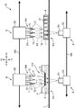
- FIG. 1 is a diagram schematically showing a cell moving device to which a cell handling device according to the present invention is applied.
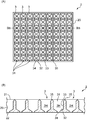
- FIG. 2A is a top view of a dish provided in the sorting container used in the cell transfer device
- FIG. 2B is a cross-sectional view taken along the line IIB-IIB in FIG.
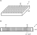
- FIG. 3A is a perspective view of a microplate used in the cell transfer device
- FIG. 3B is a cross-sectional view of the microplate.
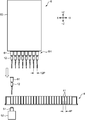
- FIG. 4 is a diagram showing the relationship between the head unit, microplate, and camera unit in the cell transfer device.
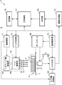
- FIG. 5 is a block diagram showing an electrical configuration of the cell transfer device.
- FIG. 1 is a diagram schematically showing a cell moving device to which a cell handling device according to the present invention is applied.
- FIG. 2A is a top view of a dish provided in the sorting container used in the cell transfer device
- FIG. 2B is a cross-sectional view taken along the line IIB-
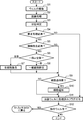
- FIG. 6 is a flowchart illustrating an example of the work selection process of the head device by the main control unit.
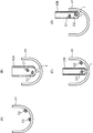
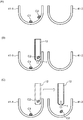
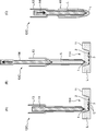
- 7A to 7D are diagrams showing an example of the cell handling operation.
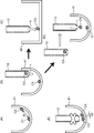
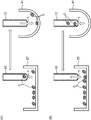
- 8A to 8C are diagrams showing an example of the cell handling operation.
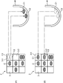
- 9A to 9E are diagrams showing an example of the cell handling operation.
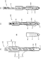
- 10A to 10C are diagrams showing an example of the cell handling operation.
- FIG. 11 is a diagram illustrating an example of a cell handling operation.
- 12A and 12B are diagrams showing an example of the cell handling operation.
- 13A and 13B are diagrams illustrating an example of the cell handling operation.
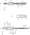
- 14A to 14D are diagrams showing an example of the cell handling operation.
- FIGS. 15A to 15C are diagrams showing an example of the cell handling operation.
- FIGS. 16A to 16C are diagrams showing an example of the cell handling operation.
- FIGS. 17A to 17C are diagrams showing an example of the cell handling operation.
- a cell, a cell mass, a cell aggregate (spheroid) or the like derived from a living body is handled.
- a cell aggregate derived from a living body is formed by aggregating several to several hundred thousand cells. Therefore, the size of the cell aggregate is various.
- Cell aggregates formed by living cells are almost spherical, but if some of the cells that make up the cell aggregates are altered or become dead cells, the shape of the cell aggregate is distorted, or The density may be non-uniform.
- cell C For testing in the fields of biotechnology and medicine, pick a usable cell aggregate from a plurality of cell aggregates of various shapes carried on a dish on a sorting stage with a chip, and use this to microplate A cell handling device (cell transfer device) that moves to release is used. In the microplate, various processes such as observation, confirmation of drug efficacy, inspection, and culture are performed on the cell aggregates.
- cell C is simply used to include the cell aggregates as described above.
- FIG. 1 is a diagram schematically showing an overall configuration of a cell transfer device S to which a cell handling device according to the present invention is applied.
- a cell moving device S that moves cells C between two containers is illustrated.
- the X and Z directions shown in FIG. 1 are, for example, the left and right directions and the up and down direction, + X is rightward, -X is leftward, + Z is upward, and -Z is downward.
- the direction orthogonal to both the X direction and the Z direction is the Y direction, for example, the front-rear direction.
- the cell transfer device S includes a translucent base 1 having a horizontal placement surface (upper surface), and a camera unit 5 (part of the cell detection unit / imaging device) disposed on the lower side of the base 1. And a head unit 6 (head device) disposed on the upper side of the base 1.
- a sorting container 11 having a dish 2 (cell holder) is placed on the first placement position P1 of the base 1, and a microplate 4 (container) is placed on the second placement position P2.
- the head unit 6 includes a head group 6H on which a chip 12 (part of a head device) that sucks and discharges cells C is mounted and includes a plurality of heads 61 that can move in the Z direction.
- the camera unit 5 and the head unit 6 are movable in the X direction and the Y direction.
- the dish 2 and the microplate 4 are placed on the upper surface of the base 1 within the movable range of the head unit 6.
- the cell transfer device S sucks the cells C individually from each of the plurality of chips 12 from the dish 2 of the sorting container 11 that holds a large number of cells C, and moves the cells C to the microplate 4. It is an apparatus for discharging cells C from a plurality of chips 12 simultaneously or individually to the microplate 4 (well 41). Hereinafter, each part of the cell transfer device S will be described.
- the base 1 is a rectangular flat plate having a predetermined rigidity and part or all of which is made of a translucent material.
- a preferred base 1 is a glass plate.
- the sorting container 11 is a container from which the cells C move, stores the medium L, and holds the cell sorting dish 2 in a state of being immersed in the medium L.
- the dish 2 is a plate for holding the cells C, and has a plurality of holding recesses 3 (holding portions) capable of individually containing and holding the cells C on the upper surface.
- the medium L is not particularly limited as long as it does not deteriorate the properties of the cells C, and can be appropriately selected depending on the type of the cells C.
- the sorting container 11 has a rectangular upper opening 11H on the upper surface side.
- the upper opening 11H is an opening for loading the cells C and picking up the sorted cells C.
- the dish 2 is disposed below the upper opening 11H.
- the sorting container 11 and the dish 2 are made of a translucent resin material or glass. This is because the cells C carried on the dish 2 can be observed by the camera unit 5 arranged below the sorting container 11.
- a plurality of cells C dispersed in a cell culture solution are injected into the sorting container 11 from a dispensing chip (not shown).
- the dispensing tip aspirates the cell culture solution together with the cells C from a container that stores a cell culture solution containing a large amount of cells C, and holds it in the dispensing tip. Thereafter, the dispensing tip is moved to the upper position of the sorting container 11 and accesses the upper surface of the dish 2 through the upper opening 11H. Then, with the tip opening of the dispensing tip immersed in the medium L of the sorting container 11, the cells C held in the dispensing tip are discharged onto the dish 2 together with the cell culture solution.
- FIG. 2A is a top view of the dish 2
- FIG. 2B is a cross-sectional view taken along the line IIB-IIB in FIG. 2A.
- the dish 2 includes a dish body 20 and a plurality of holding recesses 3 formed in the dish body 20.
- the dish body 20 is made of a flat plate member having a predetermined thickness, and has an upper surface 21 and a lower surface 22.
- the holding recess 3 has a cell C receiving opening (opening 31) on the upper surface 21 side.
- the dish 2 is immersed in the medium L in the sorting container 11. Specifically, the upper surface 21 of the dish body 20 is immersed in the culture medium L in the sorting container 11, while the lower surface 22 is held in the sorting container 11 in a state of being spaced from the bottom plate of the sorting container 11. (See FIG. 1).
- Each holding recess 3 includes an opening 31, a bottom 32, a cylindrical wall 33, a hole 34, and a boundary 35.
- the opening 31 is a square opening provided on the upper surface 21 and has a size that allows the tip opening t of the sorting chip 12 to enter.
- the bottom 32 is located inside the dish body 20 and near the lower surface 22.
- the bottom 32 is an inclined surface that is gently inclined downward toward the center (the center of the square).
- the cylindrical wall surface 33 is a wall surface extending vertically downward from the opening 31 toward the bottom 32.
- the hole 34 is a through hole that vertically penetrates between the center of the bottom 32 and the lower surface 22.
- the boundary portion 35 is a portion that is located on the upper surface 21 and serves as an opening edge of each holding recess 3, and is a ridge line that partitions the holding recesses 3.
- each holding recess 3 define an accommodation space 3H that accommodates the cells C. It is contemplated that one cell C is generally accommodated in the accommodation space 3H.
- the hole 34 is provided in order to let small cells and impurities other than the desired size escape from the accommodation space 3H. Therefore, the size of the hole 34 is selected so that cells C having a desired size cannot pass through and small cells or impurities other than the desired size can pass therethrough. As a result, the cells C to be sorted are trapped in the holding recess 3, while impurities and the like fall from the hole 34 to the bottom plate of the sorting container 11.
- the microplate 4 is a container to which the cells C are moved, and has a plurality of wells 41 (compartments that can contain the cells) into which the cells C are discharged.
- the well 41 is a hole with a bottom opened on the upper surface of the microplate 4.
- a single well 41 contains a necessary number of cells C together with the medium L.
- the microplate 4 is also made of a translucent resin material or glass. This is because the cell C carried in the well 41 can be observed by the camera unit 5 arranged below the microplate 4.
- FIG. 3A is a perspective view showing an example of the microplate 4.
- the microplate 4 includes a plate body 40 and a plurality of wells 41 arranged in a matrix on the plate body 40. Since the tip opening t of the chip 12 enters the well 41 when the cells C are discharged, each well 41 has an opening diameter that allows the chip 12 to enter with a margin.
- the reference microplate has a predetermined vertical ⁇ horizontal size (vertical 85.48 mm ⁇ horizontal 126 mm) and has a predetermined number of wells.
- a general number of wells is 24 ⁇ 16 (384 wells), and these wells are arranged in a matrix at a predetermined pitch.
- FIG. 3B is a cross-sectional view of a 384 well microplate 4. As shown in the drawing, 24 wells 41 are arranged at an equal well pitch 4P in the longitudinal direction of the microplate 4 (16 in the lateral direction).
- the camera unit 5 acquires an image of the cell C held in the holding recess 3 of the dish 2 or the well 41 (compartment) of the microplate 4 from the lower surface side.
- the lens unit 51 and the camera A main body 52 is provided.
- the camera unit 5 functions as a part of a cell detection unit that detects the cells C accommodated in the well 41.
- the lens unit 51 is an objective lens used in an optical microscope, and includes a lens group that forms an optical image with a predetermined magnification and a lens barrel that houses the lens group.
- the camera body 52 includes an image sensor such as a CCD image sensor.
- the lens unit 51 forms an optical image of the imaging object on the light receiving surface of the imaging element.
- the camera unit 5 is movable in the X direction below the base 1 along a guide rail 5G extending in the left-right direction parallel to the base 1. Although not shown in FIG. 1, the camera unit 5 is also movable in the Y direction. Further, the lens unit 51 is movable in the Z direction for the focusing operation.
- the head unit 6 is provided to move the cells C from the dish 2 to the microplate 4, and includes a head group 6H composed of a plurality of heads 61 and a head body 62 to which the head group 6H is assembled.
- a tip 12 that sucks and discharges cells C is attached to the tip of each head 61.
- the head main body 62 holds the head 61 so as to be movable up and down in the + Z and ⁇ Z directions, and is movable in the + X and ⁇ X directions along the guide rail 6G.
- the head main body 62 can also move in the Y direction.
- the head unit 6 functions as a head device that picks the cells C (suction by the chip 12) and moves and releases the picked cells C (discharge by the chip 12).
- the head 61 is formed of a hollow rod provided with a negative pressure generating mechanism.
- a piston mechanism is mounted in the hollow portion of the head 61, and suction force and discharge force are applied to the tip opening t of the chip 12 by the operation of the piston mechanism.
- the head main body 62 incorporates a power unit of the piston mechanism, an elevating mechanism for moving the head 61 in the vertical direction, and a power unit (a head drive unit 64 described later).
- FIG. 4 is a diagram showing a specific example of the head unit 6, and is a diagram showing a relationship between the microplate 4 and the camera unit 5.
- the head group 6H is exposed downward from the lower end side ( ⁇ Z side) of the head main body 62.
- FIG. 4 illustrates a head group 6H including eight heads 61 arranged linearly in the X direction. Further, in FIG. 4, one head 61 is lowered, and the chip 12 mounted on the head 61 is accessing one well 41 of the microplate 4 for picking or releasing the cells C. It is shown. Prior to this picking or release, the well 41 is imaged by the camera unit 5, and the number, nature and arrangement of the cells C moved from the microplate 4 and accommodated in the well 41 are confirmed. Thereafter, the chip 12 picks (suctions) the target cell C or releases (discharges) a new cell.
- the plurality of chips 12 mounted on the plurality of heads 61 are arranged in the X direction at a predetermined chip arrangement pitch 12P.
- the chip arrangement pitch 12P is n times the well pitch 4P of the wells 41 in the microplate 4 (n is an integer of 1 or more).
- n is an integer of 1 or more.
- FIG. 5 is a block diagram showing an electrical configuration of the cell transfer device S.
- the cell moving device S includes a control unit 7 that controls the movement of the head unit 6, the elevation of the head 61, the suction and discharge operation of the cell C, the movement and imaging operation of the camera unit 5, and the like.
- the cell moving device S includes a camera axis drive unit 53 as a mechanism for horizontally moving the camera unit 5, a servo motor 54 as a drive source for moving the lens unit 51 up and down, and a head unit axis drive as a mechanism for horizontally moving the head unit 6.
- the head drive unit 64 is provided as a mechanism for moving the head 63 up and down, and a mechanism for performing suction and discharge operations.
- the camera axis drive unit 53 includes a drive motor that horizontally moves the camera unit 5 along the guide rail 5G.
- a ball screw is laid along the guide rail 5G, the camera unit 5 is attached to a nut member screwed to the ball screw, and the drive motor rotates the ball screw forward or backward. In this mode, the camera unit 5 is moved to the target position.
- the servo motor 54 moves in the vertical direction with a predetermined resolution through a power transmission mechanism (not shown) by rotating in the forward or reverse direction. By this movement, the focal position of the lens unit 51 is adjusted to the cell C accommodated in the well 41. 5, the microplate 4 itself or the stage (base 1) on which the microplate 4 is placed is moved up and down by the servo motor 54 instead of the lens unit 51. Also good.
- the head unit shaft drive unit 63 includes a drive motor that moves the head unit 6 (head body 62) along the guide rail 6G.
- a preferable aspect is an aspect in which a ball screw and a nut member are provided, and the drive motor rotates the ball screw forward or backward.
- the head main body 62 is moved in two directions XY, the first ball screw (X direction) along the guide rail 6G and the movement attached to the first nut member screwed to the first ball screw are mounted.
- a second ball screw (Y direction) mounted on the plate is used. In this case, the head main body 62 is attached to a second nut member screwed into the second ball screw (the camera shaft driving unit 53 is also the same).
- the head driving unit 65 is a power unit for the lifting mechanism and a power unit (for example, a motor) for driving the piston mechanism, and is built in the head main body 62.
- the lifting mechanism moves the head 61 up and down between a lowered position where the head 61 extends downward from the head body 62 and a raised position where most of the head 61 is accommodated in the head body 62.
- the power unit of the piston mechanism raises and lowers the piston member disposed in the head 61 to generate a suction force and a discharge force at the tip opening t of the chip 12.
- the control unit 7 is composed of a microcomputer or the like, and by executing a predetermined program, an axis control unit 71, a head control unit 72, an imaging control unit 73, an image processing unit 74 (part of a cell detection unit), a determination It functions so as to include a unit 75, a storage unit 76, and a main control unit 77 (control unit).
- the axis control unit 71 controls the operation of the head unit axis driving unit 63. That is, the axis control unit 71 controls the head unit shaft driving unit 63 to move the head unit 6 to a predetermined target position in the horizontal direction. Movement of the head 61 (chip 12) between the sorting container 11 and the microplate 4, positioning in the vertical direction with respect to the holding recess 3 of the dish 2, and in the vertical direction with respect to the well 41 of the microplate 4 to be ejected Positioning and the like are realized by controlling the head unit shaft drive unit 64 by the shaft control unit 71.
- the head control unit 72 controls the head driving unit 64.
- the head control unit 72 controls the power unit for the lifting mechanism of the head driving unit 64 to raise and lower the head 61 to be controlled toward a predetermined target position. Further, the head control unit 72 generates a suction force or a discharge force at the tip opening portion t of the chip 12 at a predetermined timing by controlling the power unit of the piston mechanism for the head 61 to be controlled.
- the imaging control unit 73 controls the camera axis driving unit 53 to control the operation of moving the camera unit 5 along the guide rail 5G.
- the imaging control unit 73 controls the imaging operation (exposure amount, shutter timing, etc.) of the dish 2 or the microplate 4 by the camera unit 5.
- the imaging control unit 71 gives a control pulse for moving the lens unit 51 in the vertical direction at a predetermined pitch (for example, several tens of ⁇ m pitch) to the servo motor 54 for the focusing operation.
- the image processing unit 74 performs image processing such as edge detection processing and pattern recognition processing with feature amount extraction on the image data acquired by the camera body 52.
- the image processing unit 74 recognizes the presence (number) of cells C on the dish 2 (holding recesses 3) on the image based on the image of the dish 2 after the cells C are dispensed, and the distribution of the cells C.
- a process for recognizing (placement), a process for recognizing properties such as the size, shape, and color tone of the cell C are executed.
- the image processing unit 74 executes processing for recognizing the number, arrangement, and properties of the cells C accommodated in the well 41 based on the image of the well 41 to which the cells C have been moved.
- the determination unit 75 determines the state of the cell C based on the detection result of the cell C by the camera unit 5 and the image processing unit 74. That is, the determination unit 75 determines the number of cells C existing in one holding recess 3 or the well 41 and the arrangement of the cells C based on the recognition processing result of the cells C by the image processing unit 74 on the image data acquired by the camera unit 5.
- the state of the cell C including the properties such as the size, shape, and color tone of the cell C is determined.
- the well 41 based on the number of cells C, it is determined whether the number of cells C to be accommodated in one well 41 is excessive or insufficient. Further, based on the arrangement of the cells C, whether or not the plurality of cells C are arranged at a predetermined distance in the well 41, or at which position in the well 41 the cells C are in contact (picking is performed). Whether or not it is easy).
- the determination unit 75 determines whether or not the determination target cell C satisfies a predetermined criterion for the property. For example, a determination of “No” is made for the cell C whose size is too large or too small. A determination of “No” is made for a cell C whose shape is extremely distorted, or a cell C having a color tone that seems to be dead or unhealthy.
- the storage unit 76 stores various setting values, data, programs, etc. in the cell transfer device S. In addition, the storage unit 76 also stores data related to the determination criterion of the cell C. For example, the reference data regarding the size range, shape, color, and other properties of the cell C that the determination unit 75 determines to be “good”, and the cell interval that is the determination criterion for selecting either simultaneous suction or individual suction of the cell C Memorize the distance.
- the main control unit 77 comprehensively controls the operations of the camera unit 5 and the head unit 6 (head device).
- the main control unit 77 picks up the image of the dish 2 in which the cells C are seeded at the first placement position P1 (FIG. 1) where the sorting container 11 is placed, and sorts the cells C (good quality cells C) to be moved.
- the camera unit 5 and the head unit 6 are controlled through the axis control unit 71, the head control unit 72, and the imaging control unit 73 so that the selected cells C are picked.
- the main control unit 77 releases the picked cell C to the well 41, images the well 41, and the cells C in each well as intended at the second placement position P2 where the microplate 4 is placed.
- the camera unit 5 and the head unit 6 are controlled so as to perform a correction process for forming a state of being accommodated in 41.
- the dispensing operation of the cells C to the sorting container 11 is executed.
- a plurality of cells C dispersed in a cell culture solution are injected into a sorting container 11 from a dispensing tip (not shown). That is, the cells C are spread on the dish 2.
- the axis control unit 71 controls the camera axis driving unit 53 to move the camera unit 5 below the sorting container 11 along the guide rail 5G. Then, the imaging control unit 73 controls the camera unit 5 and images the cell C carried on the dish 2. The acquired image data is subjected to predetermined image processing by the image processing unit 74. Thereafter, the determination unit 75 determines to select the cells C (good quality cells C) to be moved. The sorted cell C is treated as a picking target by the chip 12 and its coordinate position is obtained.
- the shaft control unit 71 controls the head unit shaft driving unit 64 to move the head unit 6 over the sorting container 11. Then, the head control unit 72 controls the head driving unit 64, the head 61 is lowered, and the tip opening t of the chip 12 accesses the upper surface of the dish 2 through the upper opening 11H. At this time, XYZ coordinate information indicating the position of the cell C to be moved is given to the axis control unit 71 and the head control unit 72, and the chip 12 accesses the holding recess 3 in which the cell C is carried.
- the head drive unit 64 generates a suction force on the head 61. Thereby, the target cell C is sucked into the chip 12 together with the medium L from the dish 2 (holding recess 3) (picking of the cell C). Thereafter, the head 61 is raised, and the head unit 6 is moved to a position above the microplate 4. When the head unit 6 reaches above the microplate 4, the head 61 is lowered again until the tip opening t of the chip 12 enters the well 41 of the microplate 4. Then, the head driving unit 64 generates a discharge force in the head 61, and the cells C in the chip 12 are discharged together with the medium L into the well 41. The discharge state of these cells C into the well 41 is confirmed by imaging the microplate 4 (well 41) by the camera unit 5.
- the accommodation state of the cell C in the well 41 is recognized based on the image acquired by the imaging. Then, a correction operation is performed to correct each well 41 so that cells are accommodated as intended.
- the sorting operation on the dish 2 side may cause a case where the cell C is not accommodated in each well 41 as intended even though the cell selection step has been performed in advance.
- the factors include leakage of suction of the cells C from the dish 2, unintentional mixing of cells and contaminants, insufficient discharge into the well 41, damage of the cells C during movement, and the like.
- the correction operation is, for example, an operation for setting a predetermined number of cells that satisfy a predetermined determination criterion to be accommodated in the predetermined well 41.
- the main control unit 77 causes the head unit 6 to execute a predetermined correction operation on each well 41 to which the cell C has been moved, according to the result of the state determination by the determination unit 75. Specifically, the main control unit 77 causes the head unit 6 to execute one operation selected from the following operations 1 to 4 on one target well 41. -Operation 1; an operation of picking (suctioning) all the cells C accommodated in the well 41. Operation 2; an operation of picking a part of the cell C accommodated in the well 41. -Operation 3: An operation of picking a new cell C and releasing (discharging) it into the well 41. Operation 4; operation for finishing the processing for the well 41.
- the operation 1 is, for example, a picking operation executed when all of the cells C moved to the target well 41 do not satisfy a predetermined determination criterion, specifically when all the cells C are defective. It is.
- Operation 2 is a case where a plurality of cells C are moved to the target well 41, and unnecessary cells C are removed from them, or necessary cells C are taken out and moved to other wells 41 or other containers.
- Picking operation for In the operation 3 when the required number of cells C are not accommodated in the target well 41, the cell C picked in the other well 41 (cell C picked in the operation 2) or the cell C procured elsewhere is selected as the target well 41. It is an operation to add to.
- the operation 4 is selected when it is confirmed that the cell C is accommodated in the target well 41 as intended.
- the operation 4 is, so to speak, an operation in which the head unit 6 passes through the target well 41 and does not actually involve a substantial operation.
- the main control unit 77 causes the head unit 6 to execute any one of the operations 1 to 3 or does not cause the head unit 6 to perform processing on one target well 41. Make a decision.
- FIG. 6 is a flowchart showing an example of operation selection processing of the head unit 6 by the main control unit 77.
- the main control unit 77 causes the camera unit 5 to image the well 41 containing the cells C via the imaging control unit 73 (step S1).
- the image processing unit 74 performs image processing on the acquired image data to recognize the cell C (step S2), and then the determination unit 75 determines the state of the cell C (step S3).
- the above steps S1 and S2 may be executed in advance for all the wells 41 included in the microplate 4 so that the data is temporarily stored in the storage unit 76. Alternatively, the steps S1 to S3 and the following steps may be executed for each well 41.
- the main control unit 77 determines whether correction processing such as removal or addition of the cells C is necessary for the target well 41 based on the state determination result by the determination unit 75 (step S4).
- the main control unit 77 determines that the correction process is unnecessary (NO in step S4), and sets the processed flag in association with the identification symbol of the target well 41. (Step S11). This process corresponds to the selection of “Operation 4”.
- the main control unit 77 determines whether or not the cells C need to be removed from the target well 41 (step S5). If more than the necessary number of cells C are stored in the target well 41 or defective cells C are contained, it is determined that cell removal is necessary (YES in step S5). In this case, the main control unit 77 determines whether a part of the cells C may be removed or whether all of them need to be removed (step S6). If it is necessary to remove all the cells C, the whole cell removal operation corresponding to the “operation 1” is selected (step S7). On the other hand, if only part of the cells C need to be removed, the whole cell removal operation corresponding to the “operation 2” is selected (step S8).
- step S9 determines whether it is necessary to add the cell C to the target well 41 (step S9).
- the above “operation 3”. Is selected (step S10).
- This cell addition operation may use the chip 12 from which steps S7 and S8 have been removed, or may use another chip 12 that picks and holds a non-defective cell C in another well 41. . If it is not necessary to add cells (NO in step S9), step S10 is skipped.
- step S11 a processed flag is assigned in association with the identification symbol of the target well 41 (step S11). Then, it is confirmed whether or not the well 41 requiring correction processing remains (step S12). If it remains (YES in step S12), the process returns to any of steps S1, S2 or S3, and the main control unit 77 performs the same process for the next well 41. If it does not remain (NO in step S12), the process ends.
- FIGS. In these drawings, one or two wells 41 are schematically shown.
- the well 41 having a hemispherical bottom surface is illustrated, but the bottom surface may be a flat surface or a tapered surface.
- the cells C are dispersed and held in the medium L (liquid) in the well 41, but the description of the medium L is omitted in FIGS.
- Example 1> 7A to 7D are diagrams showing Example 1 of cell handling.
- Example 1 shows a specific example of the whole cell removal in the above operation 1 (step S7).
- FIG. 7A it is assumed that two cells C1 and C2 are accommodated in one well 41 to be corrected. Both the cells C1 and C2 are defective products that are determined to not satisfy the predetermined determination criterion by the determination unit 75, and are cells that need to be removed.
- the cell C1 is located near the center of the bottom surface of the well 41, and the cell C2 is located near the edge of the hemispherical bottom surface.
- the two cells C1 and C2 may be aspirated at a time by one aspiration operation of the chip 12 (at once), or the cells C1 and C2 are each aspirated, and one by one on the chip 12. Suction may be performed sequentially (individual suction).
- FIG. 7B shows an example of the former suction at a time.
- a large-diameter chip 12A having a large opening diameter at the tip opening t and a large chip inner diameter is used.
- a suction force is easily generated in the vicinity of the tip opening t in a relatively wide range, and even the cells C1 and C2 that are separated from each other can be sucked at the same time.
- the main controller 77 lowers the head 61 so that the tip opening t of the large-diameter tip 12A enters the well 41, and generates a suction force at the tip opening t. Thereby, two cells C1 and C2 can be held together with the medium in the large-diameter chip 12A.
- FIGS. 7C and 7D show examples of the latter individual suction.
- a small-diameter tip 12B having a small opening diameter at the tip opening t and a small tip inner diameter is used.
- the main control unit 77 first aligns the tip opening t of the small-diameter tip 12B with the cell C1 and sucks the cell C1, as shown in FIG. 7C.
- the head main body 62 is slightly moved to align the tip opening t with the cell C2, and the cell C2 is sucked.
- two cells C1 and C2 can be held in one small-diameter chip 12B by two suction operations.
- even the small-diameter chip 12B may be sucked simultaneously.
- the cells C that do not satisfy the determination criteria are removed from the well 41, so that the well 41 can be in a reset state. Therefore, it is possible to correct the state in which the intended cell C is accommodated in the well 41 by, for example, reintroducing a new cell C that satisfies the above-described determination criteria into the well 41.
- Example 2> 8A to 8C are diagrams showing Example 2 of cell handling.
- the second embodiment is a modification of the first embodiment, and is attached to different heads 61 in the operation of individually sucking a plurality of cells C1 and C2 (the operations in FIGS. 7C and 7D).
- tip for picking is shown.
- the target well 41 contains two cells C1 and C2 to be picked.
- the first chip 12-1 mounted on one head and the second chip 12-2 (other head device) mounted on the other head 61 are used.
- the tip opening t of the first chip 12-1 is aligned with the cell C1, and the cell C1 is aspirated.
- the head main body 62 is slightly moved to align the tip opening t of the second chip 12-2 with the cell C2 and suck the cell C2.
- two cells C1 and C2 can be held in each chip by one suction operation by the first chip 12-1 and the second chip 12-2.
- the main control unit 77 picks all the cells C to be removed on one chip 12 (example in FIG. 7). It is desirable to select whether the cells C to be shared and removed by the plurality of chips 12 are picked (example in FIG. 8). Thereby, it is possible to diversify the picking and releasing patterns of the cells C, and to improve the efficiency of the work. For example, in the example of FIG. 8, when the cells C1 and C2 are both non-defective, when there are a plurality of other wells 41 in which only one non-defective cell C is present, the wells 41 are moved to the well 41. 1.
- the second chips 12-1 and 12-2 can be accessed to add cells C1 and C2, respectively. Examples 1 and 2 can also be applied to the case where there are a plurality of cells to be removed in the partial cell removal in the operation 2 (step S8).
- FIGS. 9A to 9E are diagrams showing Example 3 of cell handling.
- the third embodiment is applied exclusively to partial cell removal in the operation 2 (step S8).
- FIG. 9A two cells C1 and C2 are accommodated in one well 41 to be corrected, and cell C2 (a part of a plurality of cells) is selected as a picking target.
- cell C2 (a part of a plurality of cells) is selected as a picking target.
- the determination unit 75 arranges the two cells C1 and C2 at a predetermined distance? Determine whether or not.
- the predetermined distance means that when the tip opening t of the chip 12 is approached to a cell to be picked and a suction force is generated, cells existing around the target cell are transferred to the chip 12. It is a distance without suction.
- the determination unit 75 determines that the distance d1 of the cell C1 with respect to the cell C2 to be picked satisfies the predetermined distance.
- the main control unit 77 aligns the tip opening t of the chip 12 with the cell C2 in the well 41 and sucks the cell C2 (picking of some cells). / Individual suction operation).
- the main control unit 77 collects (discards) the unnecessary cell as shown in FIG. 9C.
- the chip 12 (with the head main body 62) holding the cells C2 is moved to the collection container 42 to be discharged, and the cells C2 are discharged into the collection container 42.
- the main control unit 77 accesses the other chip 12 holding the cell C3 that satisfies the above-described determination criteria, and accesses the well 41 from which the cell C2 has been removed. C3 is discharged into the well 41.
- the operation in FIG. 9D corresponds to the above operation 3 (step S10).
- the operation process of FIG. Is an operation of selectively picking.
- the collection container 42 shown in FIG. 9C is replaced with a container for collecting necessary cells, and the operation in FIG. 9D is not executed.
- the cells C2 may be discharged to other wells 41 where the number of cells is insufficient (see Example 4 described below).
- FIG. 9E shows that two cells C1 and C2 are close to each other in the well 41, and the determination unit 75 determines that the distance d2 of the cell C1 with respect to the cell C2 to be picked is The case where it is determined that the distance is not satisfied is illustrated.
- the main control unit 77 causes, for example, the cells C1 and C2 to be sucked into the chip 12 by one suction operation and discharged to the collection container 42 for disposal.
- the medium in the well 41 may be agitated by alternately generating a suction force and a discharge force at the tip opening t.
- Example 4 when a plurality of cells C are arranged at a predetermined distance in the well 41, some of the cells C are picked individually. For this reason, for example, it becomes possible to pick up only unnecessary cells while leaving the necessary cells in the well 41. For such a well 41, it is only necessary to add a deficient number of cells C, and the number of cells C required for one well 41 can be efficiently aligned. In addition, cell handling such as picking necessary cells and using them separately can also be performed.
- FIGS. 10A to 10C are diagrams showing Example 4 of cell handling.
- Example 4 shows a specific example of cell addition in the operation 3 (step S10).
- FIG. 10A it is assumed that two cells C1 and C2 are accommodated in the first well 41-1 (compartment).
- the cell C is not accommodated in the second well 41-2 (other section) different from the first well 41-1. That is, the second well 41-2 is a well to which the cell C is added.
- the cells C1 and C2 are determined to be necessary cells that satisfy the determination criterion by the determination unit 75.
- the main control unit 77 aligns the tip opening t of the chip 12 with the cell C2 in the first well 41-1, and sucks the cell C2.
- the cells C1 may be sucked.
- the cell C1 is located near the center of the bottom surface of the first well 41-1, and is convenient for subsequent observation, culture, etc.
- the cell C2 located near the edge of the bottom surface is referred to as the cell C1. Picking is desirable.
- the main control unit 77 moves the chip 12 holding the cells C2 from the first well 41-1 to the second well 41-2 by moving the head main body 62. Let Then, the main control unit 77 discharges the cells C2 from the chip 12 to the second well 41-2.
- the cell C2 picked from the first well 41-1 can be moved to the second well 41-2 in which the number of cells C satisfying the determination criterion is insufficient. Therefore, the number of cells C required for one well 41 can be efficiently aligned.
- FIG. 11 is a diagram showing Example 5 of cell handling.
- the cell C picked from the well 41 is moved to another section divided according to the property of the cell C.
- a cell CA having the first property is accommodated in the first well 41-1 (compartment), and a second property different from the first property is provided in another second well 41-2 (compartment).
- cells CB are housed.
- the cells CA and CB are, for example, cells having different cell types, different sizes, different growth states, and the like. Of course, the cells CA and CB may be mixed and contained in the first and second wells 41-1 and 41-2.
- Example 5 the 1st collection container 43 (other division) and the 2nd collection container 44 (other division) divided according to the nature of cell C are prepared.
- the first collection container 43 is a container for collecting cells CA
- the second collection container 44 is a container for collecting cells CB.
- the main control unit 77 When the main controller 77 collects the necessary cells or cells CA composed of unnecessary cells, the main control unit 77 causes the tip opening t of the first chip 12-1 to access the first well 41-1, and sucks the cells CA. Subsequently, the main controller 77 moves the head main body 62 to move the first chip 12-1 holding the cells CA from the first well 41-1 to the first recovery container 43, and discharges the cells CA. . Similarly, when the main control unit 77 collects the necessary cells or cells CB made of unnecessary cells, the main control unit 77 causes the tip opening t of the second chip 12-2 to access the second well 41-1, and sucks the cells CB. Let Subsequently, the main control unit 77 moves the second main body 12-2 holding the cells CB from the second well 41-2 to the second collection container 44 by moving the head body 62, and discharges the cells CB. .
- the properties picked from the first and second wells 41-1 and 41-2 in the first and second collection containers 43 and 44 prepared according to the properties of the cell C are different. Cells CA and CB are moved. Therefore, the cells CA and CB having different properties are not mixed and stored, which is advantageous when the cells CA and CB are reused.
- the first and second collection containers 43 and 44 may be prepared separately from the microplate 4, but each of the other wells 41 provided in the microplate 4 is the first one. The first and second collection containers 43 and 44 may be used instead.
- Example 6> 12A and 12B are diagrams showing Example 6 of cell handling.
- an example is shown in which the cell C that has been moved from the movement source container to the well 41 that is the movement destination container and picked from the well 41 is returned to the movement source container.
- the cell holder 23 which is a container from which the cells C are moved is shown.
- the cell holder 23 may be a petri dish or a tube for storing the cells C together with the medium, or the dish 2 (sorting container 11) described above.
- the cells C are aspirated from the cell holder 23 by the chip 12, the chip 12 holding the cells C is moved to the well 41, and then the cells C are discharged to the well 41.
- a moving device for moving cells from the cell holder 23 to the well 41 may be a moving device prepared separately from the head unit 6, or the head unit 6 (head device) is also used. There may be.
- the main control unit 77 causes the cell C to be picked from the well 41 according to the state determination result of the cell C. For example, when it is determined that the cell C does not satisfy the determination criterion, the main control unit 77 performs an operation of returning the cell C to the cell holder 23. That is, as shown in FIG. 12B, the main control unit 77 sucks the cells C from the wells 41 with the chip 12 and moves the chip 12 holding the cells C to the cell holder 23. Then, the cells C are discharged from the chip 12 to the cell holder 23.
- the cells C that have been once moved from the cell holder 23 to the well 41 but are determined not to satisfy the determination criteria in the well 41 are returned to the cell holder 23. Accordingly, it is not necessary to separately prepare a storage place or a disposal place for the cells C that do not satisfy the above-described determination criteria.
- FIGS. 13A and 13B are diagrams showing Example 7 of cell handling.
- Example 7 shows an example in which the cells C that have been moved from the dish 2 to the well 41 and picked from the well 41 are returned to the dish 2.
- the cells C are held in the holding recesses 3 of the dish 2 from which the cells C move.
- Some holding recesses 3 are empty holding recesses that do not hold cells C.
- the second holding recess 3-2 adjacent to the first holding recess 3-1 is the empty holding recess.
- the main control unit 77 does not return both of the cells C1 and C2 to the first holding recess 3-1, which originally held the cells, but instead uses the empty second holding The recess 3-2 is used. That is, the cell C1 is returned to the first holding recess 3-1, and the cell C2 is returned to the second holding recess 3-2.
- Example 7 the cells C that were once moved from the dish 2 to the well 41 and then returned to the dish 2 are held again in a state of being arranged in the holding recess 3. That is, the cells C1 and C2 can be held in the first and second holding recesses 3-1 and 3-2, respectively. Therefore, when the cell C moves from the dish 2 thereafter, the head unit 6 can easily perform the moving operation efficiently.
- FIGS. 14A to 15C are diagrams showing Example 8 of cell handling.
- Example 8 shows an example of the reset operation of the well 41 using the large chip 12C.
- “reset” is to remove all the cells C from the well 41 to which the cells C have been moved once, and to enable the acceptance of new cells C.
- FIG. 14A is a cross-sectional view showing the structure of the large chip 12C.
- the large chip 12 ⁇ / b> C includes a syringe 13 that includes a tubular passage 13 ⁇ / b> H serving as a suction path for the cells C and a plunger 14 that moves forward and backward in the tubular passage 13 ⁇ / b> H while being in sliding contact with the inner peripheral wall of the syringe 13.
- the syringe 13 includes a syringe base end portion 131 made of a large-diameter cylindrical body, a syringe main body portion 132 made of a thin and long cylindrical body, and a tapered tube portion 133 connecting the base end portion 131 and the main body portion 132. including.
- the tubular passage 13H is formed in the syringe main body 132.
- the tip opening t described above is provided at the tip of the syringe body 132.
- the plunger 14 includes a plunger base end portion 141 formed of a cylindrical body, a columnar plunger main body portion 142, and a taper portion 143 that connects the base end portion 141 and the main body portion 142. In a state where the plunger 14 is inserted into the syringe 13 most deeply, the distal end portion 144 of the plunger 14 slightly projects from the distal end opening t.
- the plunger 14 is assembled to the syringe 13 so that the plunger main body 142 slides in the vertical direction within the tubular passage 13H of the syringe main body 132.
- a suction force is generated at the tip opening t.
- a discharge force is generated at the tip opening t.
- the main control unit 77 executes the reset operation of the well 41 as shown in FIGS. 14C to 15C using the large chip 12C described above (the whole cell removal in the above operation 1). ).
- the tubular passage 13H of the large chip 12C has a volume capable of sucking all the medium L filled in the well 41.
- the main control unit 77 moves the plunger 14 up and down by a predetermined stroke. As a result, suction force and discharge force are alternately generated at the tip opening t, and the cells C that have settled at the bottom of the well 41 are swung upward by the flow of the medium L. By this. The cells C can be easily sucked into the large chip 12C. And as shown in FIG.14 (D), the main control part 77 raises the plunger 14, and attracts
- the main control unit 77 moves the large chip 12C holding the cells C to the disposal location of the cells C.
- FIG. 15A an example in which the disposal place is the sorting container 11 is shown (for ease of illustration, the sorting container 11 is drawn with a considerably reduced size. ).
- the main control unit 77 causes the tip opening t of the large chip 12 ⁇ / b> C to enter the upper opening 11 ⁇ / b> H, and is immersed in the medium L stored in the sorting container 11. Then, the plunger 14 is lowered, and the cells C held in the tubular passage 13H are discharged together with the medium L to the sorting container 11. The discharged cells C are held on the dish 2.
- the main control unit 77 raises the plunger 14 while the tip opening t is immersed in the culture medium L as shown in FIG. Thereby, the culture medium L is sucked into the tubular passage 13H of the large chip 12C. Then, the main control unit 77 moves the large chip 12C holding the culture medium L to the position of the well 41 that has been emptied first. Subsequently, as shown in FIG. 15C, the medium L is discharged from the large chip 12 ⁇ / b> C into the well 41. As a result, the well 41 is ready to accept a new cell C.
- FIGS. 16A to 17C are diagrams showing Example 9 of cell handling.
- Example 9 shows an example of the picking operation of the cell C from the well 41 and the additional operation of the cell C to the well 41 using the small chip 12D.
- FIG. 16A is a cross-sectional view showing the structure of the small chip 12D.
- the small chip 12D includes a small-diameter syringe 15 that includes a tubular passage 15H serving as a suction path for the cells C and a plunger 16 that moves forward and backward in the tubular passage 15H while slidingly contacting the inner peripheral wall of the syringe 15.
- the syringe 15 includes a syringe base end portion 151 made of a large-diameter cylindrical body, a syringe main body portion 152 made of a thin and long cylindrical body, and a tapered tube portion 153 connecting the base end portion 151 and the main body portion 152. including.
- the tubular passage 15H is formed in the syringe main body 152.
- the tip opening t described above is provided at the tip of the syringe body 152.
- the plunger 16 includes a plunger base end portion 161 made of a cylindrical body, a needle-like plunger main body portion 162, and a taper portion 163 that connects the base end portion 161 and the main body portion 162. In a state where the plunger 16 is inserted most deeply into the syringe 15, the distal end portion 164 of the plunger 16 slightly projects from the distal end opening t.
- the plunger 16 is assembled to the syringe 15 so that the plunger main body 162 slides up and down in the tubular passage 15H of the syringe main body 152.
- a suction force is generated at the tip opening t.
- a discharge force is generated at the tip opening t.
- the main control unit 77 performs the picking and adding operation of the cell C as shown in FIGS. 16C to 17C using the small chip 12D described above (all the operations 1 described above). Cell removal or partial cell removal in action 2).
- the volume of the tubular passage 15H of the small chip 12D is a volume capable of sucking only a part of the medium L filled in the well 41.
- the main control unit 77 causes the small chip 12D to enter the well 41 and causes the tip opening t to approach the cell C in the medium L. Then, the plunger 16 is raised to suck the cells C together with the surrounding medium L into the tubular passage 15H. By this suction, the well 41 is in a state where the cells C are not present and only the medium L is present, or only the necessary cells C remain together with the medium L.
- the main control unit 77 moves the small chip 12D holding the cells C to the sorting container 11 which is a disposal place of the cells C. Subsequently, the main control unit 77 causes the tip opening t of the small chip 12D to enter the upper opening 11H, and is immersed in the culture medium L stored in the sorting container 11. At this time, the position may be aligned with a specific holding recess 3. Then, the plunger 16 is lowered, and the cells C held in the tubular passage 15H are discharged together with the culture medium L to the sorting container 11. The discharged cells C are held on the dish 2.
- the main control unit 77 holds the tip opening t of the small chip 12D in the cell CT that is carried in a place different from the discard area of the dish 2 and that satisfies the above-mentioned determination criteria. To align. Then, the plunger 16 is raised, and the cell CT is sucked together with the medium L. Thereafter, the main control unit 77 moves the small chip 12D holding the cells C to the position of the well 41 where the cells C were picked first. Subsequently, as shown in FIG. 17C, the cells CT are discharged together with the medium L from the small chip 12D to the well 41. Thereby, the cell CT can be added to the well 41.
- the camera unit 5 is exemplified as an example of the cell detection unit accommodated in the well 41. That is, the example which detected the cell C based on the image was shown.
- the cell detection unit may be a physical quantity sensor such as an optical or acoustic sensor.
- the cell C may be recognized by irradiating the cell C with light and observing the fluorescence.
- a sonar equipped with a sound source may be used and the cell C may be recognized based on the reverberant sound.
- the microplate 4 having the wells 41 is exemplified as the container having the compartment that can accommodate the cells.
- the container may be the dish 2, and the section may be the holding recess 3, and the cell C may be picked or released from the holding recess 3 and the cell C may be added.
- the head unit 6 including the chip 12 is illustrated as an example of the head device, and the suction of the cell C to the chip 12 as the picking mode and the suction of the cell C as the release mode The discharge from the chip 12 was illustrated.
- the head device may be any device that can hold one or a plurality of cells C and release the held cells C by mechanical, electrical, or magnetic force.
- a cell handling device includes a container having a compartment that can accommodate cells, a cell detection unit that detects cells contained in the compartment, picking of cells, and movement and release of the picked cells.
- a cell state including at least one of the number, properties, and arrangement of cells contained in the compartment based on a detection result of the head device to be performed, a control unit for controlling the operation of the head device, and a detection result of the cell detection unit
- this cell handling device based on the result of the cell state determination, for example, when cells having an inappropriate state are accommodated in the compartment, all or a part of the cells are picked, the cells are insufficient In this case, either an operation for adding a new cell to the compartment or an operation for finishing the processing for the compartment containing the cell as intended is selected. Therefore, the container in which the cells are once accommodated in the compartment can be corrected to the state in which the cells are accommodated as intended by the cell handling device.
- the determination by the determination unit is to determine whether the determination target cell satisfies a predetermined determination criterion regarding the property, and the control unit is configured to determine the determination. It is desirable to cause the head device to perform an operation of picking all the cells determined not to meet the criteria from the compartment.
- this cell handling device According to this cell handling device, cells that do not satisfy the determination criteria are removed from the compartment, so to speak, the compartment can be reset. Therefore, it is possible to correct the cell to be accommodated as intended by, for example, re-injecting the cell satisfying the determination criterion into the section.
- the control when the determination unit determines in the state determination that there are a plurality of cells in the partition and the cells are arranged at a predetermined distance, the control Preferably, the unit causes the head device to perform an operation of picking some of the plurality of cells.
- the container has another compartment separately from the compartment, and the control unit moves the cell picked from the compartment to the other compartment and releases the operation. It is desirable to have the head device execute.
- cells picked from the compartment can be moved, for example, to another compartment where the number of good cells is insufficient. Therefore, the number of cells required for one compartment can be efficiently arranged.
- the cell handling device further includes another compartment that is classified according to the nature of the cell, and the control unit moves the cell picked from the compartment to the other compartment. It is desirable to cause the head device to perform an operation of releasing and releasing.
- the picked cells are moved to other compartments classified according to the properties of the cells. Therefore, cells having different properties are not mixed and stored, which is advantageous when reusing these cells.
- the other compartment may be another compartment provided in the container or another container.
- the cell handling device further includes a cell holder that holds cells accommodated in the compartment of the container, and a moving device that moves cells from the cell holder to the compartment of the container, and the determination unit includes It is desirable to perform the state determination on the cells moved from the cell holder to the compartment.
- the state of the cells moved from the cell holder to the compartment of the container is determined by the moving device. That is, the cell holder is a cell movement source and the container is a cell movement destination, and the cell state is determined at the movement destination. Therefore, the cell handling device of the present invention can be applied to a general cell transfer device to form a state in which cells are accommodated as intended in the compartment of the transfer destination container.
- the determination unit performs a state determination for determining whether or not a predetermined determination criterion regarding the property is satisfied for the cells moved from the cell holder to the compartment,
- the control unit causes the head device to perform an operation of picking the cell from the compartment and returning the cell to the cell holder in accordance with the result of the state determination.
- this cell handling apparatus for example, cells that have been once moved to the compartment but are determined not to satisfy the determination criteria are returned to the cell holder. Therefore, a storage place or a disposal place for cells that do not satisfy the determination criteria is not required.
- the cell holder includes a plurality of holding units that independently hold one or a plurality of cells, and the control unit performs the operation of returning the picked cells to the cell holder. It is desirable to cause the head device to perform an operation of returning the cells to an empty holding unit among the holding units.
- the cells that are once moved from the cell holder to the compartment and then returned to the cell holder are again held in a state of being arranged in the holding portion of the cell holder. Accordingly, when the cells are moved from the cell holder thereafter, the moving device can easily perform the moving operation efficiently.
- the head device also serves as the moving device. Thereby, the structure of a cell handling apparatus can be simplified.
- the cells are dispersed in the liquid in the compartment, and the head device includes a tip having a tip opening capable of sucking the cells and discharging the sucked cells,
- the cells are sucked together with the surrounding liquid during the picking, and the cells are discharged together with the sucked liquid during the release.
- this cell handling apparatus it is possible to execute picking and releasing of cells by sucking and discharging the chip, and it is possible to simplify and facilitate these operations.
- the control unit sucks the plurality of cells into the chip when the distance between the plurality of cells is shorter than a predetermined distance.
- the head device can be caused to perform an operation of sucking each of the plurality of cells by the individual suction operation to the chip. desirable.
- the chip can be caused to perform a suction operation according to the arrangement mode of the cells in the compartment. That is, when a plurality of cells are arranged close to the compartment, it is difficult to suck these cells individually with the chip. In this case, the plurality of cells are sucked into the chip by one suction operation. On the other hand, when a plurality of cells are spaced apart from each other in the compartment, these cells can be individually aspirated with the chip. Therefore, in this case, each of the cells is sucked into the chip by a separate suction operation.
- the head device in addition to the head device, the head device further includes another head device, and the control unit picks up a plurality of cells from the section, and the head device or the other head device. It is desirable to select whether the plurality of cells are picked or whether the plurality of cells are picked by the head device and the other head device.
- the picking pattern of cells can be diversified by utilizing the head device and the other head device.
- the cell detection unit includes an imaging device that acquires an image of a cell accommodated in the compartment.
- this cell handling device for example, image processing is performed on an image acquired by the imaging device, so that cells contained in the compartment can be detected easily and reliably.
- a cell handling device capable of bringing cells into a container as intended in a container having a compartment for containing cells.
Landscapes
- Health & Medical Sciences (AREA)
- Chemical & Material Sciences (AREA)
- Engineering & Computer Science (AREA)
- Life Sciences & Earth Sciences (AREA)
- Bioinformatics & Cheminformatics (AREA)
- Organic Chemistry (AREA)
- Zoology (AREA)
- Wood Science & Technology (AREA)
- General Health & Medical Sciences (AREA)
- Clinical Laboratory Science (AREA)
- Biochemistry (AREA)
- Genetics & Genomics (AREA)
- Biomedical Technology (AREA)
- Biotechnology (AREA)
- Microbiology (AREA)
- Sustainable Development (AREA)
- General Engineering & Computer Science (AREA)
- Analytical Chemistry (AREA)
- Chemical Kinetics & Catalysis (AREA)
- Molecular Biology (AREA)
- Hematology (AREA)
- Human Computer Interaction (AREA)
- Computer Hardware Design (AREA)
- Apparatus Associated With Microorganisms And Enzymes (AREA)
Abstract
細胞ハンドリング装置は、細胞を収容可能な区画を有する容器と、前記区画に収容された細胞を検出する細胞検出部と、細胞のピッキング、ピッキングした細胞の移動及びリリースを行うヘッド装置と、前記ヘッド装置の動作を制御する制御部と、前記細胞検出部の検出結果に基づき、前記区画に収容された細胞の個数、性質及び配置の少なくとも一つを含む、細胞の状態判定を行う判定部とを備える。前記制御部は、前記判定部の前記状態判定の結果に応じて、前記ヘッド装置に、前記区画に収容された細胞の全てをピッキングさせる動作、前記区画に収容された細胞の一部をピッキングさせる動作、新たな細胞をピッキングして、前記区画にリリースさせる動作、及び、前記区画に対する処理を終える動作、から選ばれる一つの動作を実行させる。
Description
本発明は、細胞のピッキング、ピッキングした細胞の移動及びリリースを行うヘッド装置を備えた細胞ハンドリング装置に関する。
例えば医療や生物学的な研究の用途では、単細胞、或いは細胞が三次元的に凝集してなる細胞凝集塊、或いは細胞の断片から塊化培養した細胞塊(以下、これらを本明細書では単に細胞という)が、観察、薬効確認、検査若しくは培養等の処理作業のために、マトリクス配列されたウェルを有するマイクロプレートの、前記ウェルに収容されることがある。前記ウェルに収容される細胞は、細胞を収容可能な保持凹部を有するディッシュ上において選別される。
すなわち、前記ディッシュには、分注チップを用いて細胞懸濁液に分散された細胞群が撒かれる。ここで撒かれる細胞群は、多様なサイズ、形状の細胞を含む。これらの細胞から、前記ディッシュを撮像して画像処理を施す等して、前記処理作業に適した細胞が選別される。選ばれた細胞は、当該細胞の吸引及び吐出が可能なチップにて前記ディッシュからピッキングされると共に、前記マイクロプレートまで移動され、前記ウェルに吐出(リリース)される。このような細胞の、例えば前記ディッシュから前記マイクロプレートまで移動には、細胞のピッキング、ピッキングした細胞の移動及びリリースを行うヘッド装置を備えた細胞ハンドリング装置が用いられる(例えば特許文献1参照)。
細胞の移動先となる前記ウェルには、意図する通りの状態で細胞が収容されていることが、その後の処理作業を円滑に進めるために望ましい。例えば、前記ウェルに収容された細胞の個数、細胞のサイズ、形状、生死及び良否などの細胞の性質、前記ウェルにおける細胞の配置などを含む細胞の状態が不適切であると、前記処理作業に支障を来す場合がある。しかし、従来は、移動先の容器において、意図する通りに細胞の状態を修正することが可能な細胞ハンドリング装置は提案されていない。
本発明の目的は、細胞を収容する区画を備えた容器に、意図通りに細胞が収容された状態とすることが可能な細胞ハンドリング装置を提供することにある。
本発明の一局面に係る細胞ハンドリング装置は、細胞ハンドリング装置は、細胞を収容可能な区画を有する容器と、前記区画に収容された細胞を検出する細胞検出部と、細胞のピッキング、ピッキングした細胞の移動及びリリースを行うヘッド装置と、前記ヘッド装置の動作を制御する制御部と、前記細胞検出部の検出結果に基づき、前記区画に収容された細胞の個数、性質及び配置の少なくとも一つを含む、細胞の状態判定を行う判定部とを備える。前記制御部は、前記判定部の前記状態判定の結果に応じて、前記ヘッド装置に、前記区画に収容された細胞の全てをピッキングさせる動作、前記区画に収容された細胞の一部をピッキングさせる動作、新たな細胞をピッキングして、前記区画にリリースさせる動作、及び、前記区画に対する処理を終える動作、から選ばれる一つの動作を実行させる。
以下、本発明の実施形態を、図面に基づいて詳細に説明する。本発明に係る細胞ハンドリング装置では、生体由来の細胞、細胞塊或いは細胞凝集塊(スフェロイド;spheroid)等がハンドリング対象物とされる。例えば生体由来の細胞凝集塊は、細胞が数個~数十万個凝集して形成されている。そのため、細胞凝集塊の大きさは様々である。生きた細胞が形成する細胞凝集塊は略球形であるが、細胞凝集塊を構成する細胞の一部が変質したり、死細胞となっていたりすると、細胞凝集塊の形状は歪になる、あるいは密度が不均一となる場合がある。バイオ関連技術や医薬の分野における試験において、選別ステージ上のディッシュに担持された種々の形状を呈する複数の細胞凝集塊の中から、使用可能な細胞凝集塊をチップでピッキッングし、これをマイクロプレートまで移動してリリースする細胞ハンドリング装置(細胞移動装置)が用いられる。マイクロプレートでは、細胞凝集塊に対して、観察、薬効確認、検査、培養等の各種の処理が実行される。以下の説明では、上記のような細胞凝集塊を含む意味で、簡略的に細胞Cと表現する。
[細胞移動装置の全体構成]
図1は、本発明に係る細胞ハンドリング装置が適用された細胞移動装置Sの全体構成を概略的に示す図である。ここでは、細胞Cを2つの容器間で移動させる細胞移動装置Sを例示している。なお、図1に示すX、Z方向は例えば左右方向、上下方向であり、+Xは右方、-Xは左方、+Zは上方、-Zは下方である。また、X方向及びZ方向の双方と直交する方向がY方向であり、例えば前後方向である。
図1は、本発明に係る細胞ハンドリング装置が適用された細胞移動装置Sの全体構成を概略的に示す図である。ここでは、細胞Cを2つの容器間で移動させる細胞移動装置Sを例示している。なお、図1に示すX、Z方向は例えば左右方向、上下方向であり、+Xは右方、-Xは左方、+Zは上方、-Zは下方である。また、X方向及びZ方向の双方と直交する方向がY方向であり、例えば前後方向である。
細胞移動装置Sは、水平な載置面(上面)を有する透光性の基台1と、基台1の下方側に配置されたカメラユニット5(細胞検出部の一部/撮像装置)と、基台1の上方側に配置されたヘッドユニット6(ヘッド装置)とを含む。基台1の第1載置位置P1には、ディッシュ2(細胞ホルダー)を備えた選別容器11が載置され、第2載置位置P2にはマイクロプレート4(容器)が載置されている。ヘッドユニット6は、細胞Cの吸引及び吐出を行うチップ12(ヘッド装置の一部)が装着され、Z方向に移動可能なヘッド61を複数備えるヘッド群6Hを含む。カメラユニット5及びヘッドユニット6は、X方向及びY方向に移動可能である。ディッシュ2及びマイクロプレート4は、ヘッドユニット6の移動可能範囲内において、基台1の上面に載置されている。
大略的に細胞移動装置Sは、細胞Cを多数保持している選別容器11のディッシュ2から複数のチップ12の各々で細胞Cを個別に吸引し、これをマイクロプレート4まで移動すると共に、当該マイクロプレート4(ウェル41)に複数のチップ12から細胞Cを同時又は個別に吐出する装置である。以下、細胞移動装置Sの各部を説明する。
基台1は、所定の剛性を有し、その一部又は全部が透光性の材料で形成される長方形の平板である。好ましい基台1は、ガラスプレートである。基台1をガラスプレートのような透光性材料によって形成することで、基台1の下方に配置されたカメラユニット5にて、基台1の上面に配置された選別容器11(ディッシュ2)及びマイクロプレート4を、当該基台1を通して撮像させることが可能となる。
選別容器11は、細胞Cの移動元となる容器であり、培地Lを貯留し、細胞選別用のディッシュ2を培地Lに浸漬される状態で保持している。ディッシュ2は、細胞Cを保持するプレートであり、細胞Cを個別に収容して保持することが可能な保持凹部3(保持部)を上面に複数有している。培地Lは、細胞Cの性状を劣化させないものであれば特に限定されず、細胞Cの種類により適宜選定することができる。
選別容器11は、その上面側に矩形の上部開口11Hを備えている。上部開口11Hは、細胞Cの投入、並びに、選別された細胞Cをピックアップするための開口である。ディッシュ2は、上部開口11Hの下方に配置されている。選別容器11及びディッシュ2は、透光性の樹脂材料やガラスで作製されたものが用いられる。これは、選別容器11の下方に配置されたカメラユニット5により、ディッシュ2に担持された細胞Cを観察可能とするためである。
選別容器11には、図略の分注チップから、細胞培養液に分散された状態の複数の細胞Cが注入される。前記分注チップは、多量の細胞Cを含む細胞培養液を貯留する容器から、細胞Cと共に細胞培養液を吸引し、当該分注チップ内に保持する。その後、前記分注チップは、選別容器11の上空位置へ移動され、上部開口11Hを通してディッシュ2の上面にアクセスする。そして、前記分注チップの先端開口が選別容器11の培地Lに浸漬された状態で、前記分注チップ内に保持された細胞Cが細胞培養液と共にディッシュ2の上へ吐出される。
ディッシュ2の詳細構造を説明する。図2(A)は、ディッシュ2の上面図、図2(B)は、図2(A)のIIB-IIB線断面図である。ディッシュ2は、ディッシュ本体20と、該ディッシュ本体20に形成される複数の保持凹部3とを備えている。ディッシュ本体20は、所定の厚みを有する平板状の部材からなり、上面21と下面22とを有する。保持凹部3は、上面21の側に細胞Cの受け入れ開口(開口部31)を有する。ディッシュ2は、選別容器11内の培地L中に浸漬される。詳しくは、ディッシュ本体20の上面21が選別容器11内の培地L中に浸漬される一方、下面22が選別容器11の底板に対して間隔を置いた状態で、選別容器11内で保持される(図1参照)。
保持凹部3の各々は、開口部31、底部32、筒状の壁面33、孔部34及び境界部35を含む。本実施形態では、上面視で正方形の保持凹部3がマトリクス状に配列されている例を示している。開口部31は、上面21に設けられた正方形の開口であり、選別用のチップ12の先端開口部tの進入を許容するサイズを有する。底部32は、ディッシュ本体20の内部であって、下面22の近くに位置している。底部32は、中心(前記正方形の中心)に向けて緩く下り傾斜する傾斜面である。筒状の壁面33は、開口部31から底部32に向けて鉛直下方に延びる壁面である。孔部34は、底部32の前記中心と下面22との間を鉛直に貫通する貫通孔である。境界部35は、上面21に位置し、各保持凹部3の開口縁となる部分であって、保持凹部3同士を区画する稜線である。
各保持凹部3の底部32及び筒状の壁面33は、細胞Cを収容する収容空間3Hを区画している。収容空間3Hには、一般的には1個の細胞Cが収容されることが企図されている。孔部34は、所望のサイズ以外の小さな細胞や夾雑物を収容空間3Hから逃がすために設けられている。従って、孔部34のサイズは、所望のサイズの細胞Cは通過できず、所望のサイズ以外の小さな細胞や夾雑物を通過させるサイズに選ばれている。これにより、選別対象となる細胞Cは保持凹部3にトラップされる一方で、夾雑物等は孔部34から選別容器11の底板に落下する。
図1に戻って、マイクロプレート4は、細胞Cの移動先となる容器であり、細胞Cが吐出される複数のウェル41(細胞を収容可能な区画)を有する。ウェル41は、マイクロプレート4の上面に開口した有底の孔である。1つのウェル41には、培地Lと共に必要個数の細胞Cが収容される。マイクロプレート4もまた、透光性の樹脂材料やガラスで作製されたものが用いられる。これは、マイクロプレート4の下方に配置されたカメラユニット5により、ウェル41に担持された細胞Cを観察可能とするためである。
図3(A)は、マイクロプレート4の一例を示す斜視図である。マイクロプレート4は、プレート本体40と、このプレート本体40にマトリクス状に配列された複数のウェル41とを含む。細胞Cの吐出時、ウェル41にはチップ12の先端開口部tが進入するので、各ウェル41は余裕を持ってチップ12の進入を許容する開口径を有している。
市販されているマイクロプレートには基準サイズが存在する。基準マイクロプレートは、所定の縦×横サイズ(縦85.48mm×横126mm)を備え、所定数のウェルを有する。一般的なウェル数は、24×16個(384ウェル)であり、これらウェルが所定のピッチでマトリクス配列されている。図3(B)は、384ウェルのマイクロプレート4の断面図である。図示する通り、マイクロプレート4の長手方向には、24個のウェル41が均等なウェルピッチ4Pで配列されている(短手方向には16個)。
カメラユニット5は、ディッシュ2の保持凹部3又はマイクロプレート4のウェル41(区画)に保持されている細胞Cの画像を、これらの下面側から撮像して取得するもので、レンズ部51及びカメラ本体52を備える。本実施形態において、カメラユニット5は、ウェル41に収容された細胞Cを検出する細胞検出部の一部として機能する。
レンズ部51は、光学顕微鏡に用いられている対物レンズであり、所定倍率の光像を結像させるレンズ群と、このレンズ群を収容するレンズ鏡筒とを含む。カメラ本体52は、CCDイメージセンサのような撮像素子を備える。レンズ部51は、前記撮像素子の受光面に撮像対象物の光像を結像させる。カメラユニット5は、基台1と平行に左右方向に延びるガイドレール5Gに沿って、基台1の下方においてX方向に移動可能である。なお、図1では図示していないが、カメラユニット5は、前記Y方向にも移動可能である。また、レンズ部51は、合焦動作のためにZ方向に移動可能である。
ヘッドユニット6は、細胞Cをディッシュ2からマイクロプレート4へ移動させるために設けられ、複数本のヘッド61からなるヘッド群6Hと、このヘッド群6Hが組み付けられるヘッド本体62とを含む。各ヘッド61の先端には、細胞Cの吸引及び吐出を行うチップ12が装着されている。ヘッド本体62は、ヘッド61を+Z及び-Z方向に昇降可能に保持し、ガイドレール6Gに沿って+X及び-X方向に移動可能である。なお、図1では図示していないが、ヘッド本体62は、前記Y方向にも移動可能である。本実施形態において、ヘッドユニット6は、細胞Cのピッキング(チップ12による吸引)、ピッキングした細胞Cの移動及びリリース(チップ12による吐出)を行うヘッド装置として機能する。
ヘッド61は、負圧発生機構が付設された中空のロッドからなる。ヘッド61の中空部内には例えばピストン機構が搭載され、該ピストン機構の動作によってチップ12の先端開口部tに吸引力及び吐出力が与えられる。ヘッド本体62には、前記ピストン機構の動力部と、ヘッド61を上下方向に移動させる昇降機構及びその動力部(後述のヘッド駆動部64)が内蔵されている。
図4は、ヘッドユニット6の具体例を示す図であって、マイクロプレート4及びカメラユニット5との関係を示す図である。ヘッドユニット6において、ヘッド本体62の下端側(-Z側)から、ヘッド群6Hが下方に露出している。図4では、X方向に直線状に並ぶ8本のヘッド61からなるヘッド群6Hを例示している。また、図4では、一つのヘッド61が下降し、該ヘッド61に装着されたチップ12が、細胞Cのピッキング若しくはリリースのために、マイクロプレート4の一つのウェル41にアクセスしている状態が示されている。このピッキング又はリリースに先立ち、カメラユニット5によりウェル41が撮像され、マイクロプレート4から移動され当該ウェル41に収容されている細胞Cの個数、性質及び配置が確認される。その後、チップ12により、ターゲットとする細胞Cのピッキング(吸引)又は新たな細胞のリリース(吐出)が行われる。
複数のヘッド61に各々装着された複数のチップ12は、所定のチップ配列ピッチ12PでX方向に配列されている。このチップ配列ピッチ12Pは、マイクロプレート4におけるウェル41のウェルピッチ4Pのn倍(nは1以上の整数)である。例えば、384ウェルのマイクロプレート4の場合、上述の通りウェルピッチ4Pは4.5mmであるので、チップ配列ピッチ12Pは4.5mm×2=9.0mmに設定される。このようにウェルピッチ4Pとチップ配列ピッチ12Pとを選定することで、複数のチップ12を複数のウェル41に対して同時にアクセスさせ、同時に細胞Cを吐出させることが可能となる。
[細胞移動装置の電気的構成]
図5は、細胞移動装置Sの電気的構成を示すブロック図である。細胞移動装置Sは、ヘッドユニット6の移動、ヘッド61の昇降、細胞Cの吸引及び吐出動作、並びにカメラユニット5の移動及び撮像動作等を制御する制御部7を備える。また、細胞移動装置Sは、カメラユニット5を水平移動させる機構としてカメラ軸駆動部53、レンズ部51を上下動させる駆動源としてサーボモータ54、ヘッドユニット6を水平移動させる機構としてヘッドユニット軸駆動部63、ヘッド61を昇降させる機構並びに吸引及び吐出動作を行わせる機構としてヘッド駆動部64を備えている。
図5は、細胞移動装置Sの電気的構成を示すブロック図である。細胞移動装置Sは、ヘッドユニット6の移動、ヘッド61の昇降、細胞Cの吸引及び吐出動作、並びにカメラユニット5の移動及び撮像動作等を制御する制御部7を備える。また、細胞移動装置Sは、カメラユニット5を水平移動させる機構としてカメラ軸駆動部53、レンズ部51を上下動させる駆動源としてサーボモータ54、ヘッドユニット6を水平移動させる機構としてヘッドユニット軸駆動部63、ヘッド61を昇降させる機構並びに吸引及び吐出動作を行わせる機構としてヘッド駆動部64を備えている。
カメラ軸駆動部53は、ガイドレール5Gに沿ってカメラユニット5を水平移動させる駆動モータを含む。好ましい態様は、ガイドレール5Gに沿ってボールねじが敷設され、該ボールねじに螺合されたナット部材にカメラユニット5が取り付けられ、前記駆動モータが前記ボールねじを正回転又は逆回転させることにより、カメラユニット5を目標位置へ移動させる態様である。
サーボモータ54は、正回転又は逆回転することで、図略の動力伝達機構を介して、レンズ部51を所定の分解能で上下方向に移動させる。この移動によって、ウェル41に収容された細胞Cにレンズ部51の焦点位置が合わせられる。なお、図5において点線で示しているように、レンズ部51ではなく、サーボモータ54によってマイクロプレート4自体、若しくはマイクロプレート4が載置されるステージ(基台1)を上下動させるようにしても良い。
ヘッドユニット軸駆動部63は、ガイドレール6Gに沿ってヘッドユニット6(ヘッド本体62)を移動させる駆動モータを含む。好ましい態様は、ボールねじ及びナット部材を具備し、前記駆動モータが前記ボールねじを正回転又は逆回転させる態様である。なお、ヘッド本体62をXYの2方向に移動させる場合は、ガイドレール6Gに沿った第1ボールねじ(X方向)と、第1ボールねじに螺合された第1ナット部材に装着された移動板に搭載された第2ボールねじ(Y方向)とを用いる。この場合、ヘッド本体62は第2ボールねじに螺合された第2ナット部材に装着される(カメラ軸駆動部53も同様)。
ヘッド駆動部65は、前記昇降機構のための動力部、前記ピストン機構を駆動するための動力部(例えばモータ)であって、ヘッド本体62に内蔵されている。前記昇降機構はヘッド本体62からヘッド61が下方に延び出した下降位置と、ヘッド61の大部分がヘッド本体62の収容された上昇位置との間で、ヘッド61を上下移動させる。前記ピストン機構の動力部は、ヘッド61内に配置されたピストン部材を昇降させることで、チップ12の先端開口部tに、吸引力及び吐出力を発生させる。
制御部7は、マイクロコンピュータ等からなり、所定のプログラムが実行されることで、軸制御部71、ヘッド制御部72、撮像制御部73、画像処理部74(細胞検出部の一部)、判定部75、記憶部76及び主制御部77(制御部)を備えるように機能する。
軸制御部71は、ヘッドユニット軸駆動部63の動作を制御する。すなわち、軸制御部71は、ヘッドユニット軸駆動部63を制御することで、ヘッドユニット6を水平方向の所定の目標位置へ移動させる。ヘッド61(チップ12)の、選別容器11とマイクロプレート4との間の移動、ディッシュ2の保持凹部3に対する鉛直上空での位置決め、並びに吐出対象となるマイクロプレート4のウェル41に対する鉛直上空での位置決め等は、軸制御部71によるヘッドユニット軸駆動部64の制御によって実現される。
ヘッド制御部72は、ヘッド駆動部64を制御する。ヘッド制御部72は、ヘッド駆動部64の前記昇降機構のための動力部を制御することにより、制御対象とするヘッド61を所定の目標位置に向けて昇降させる。また、ヘッド制御部72は、制御対象とするヘッド61についての前記ピストン機構の動力部を制御することにより、所定のタイミングでチップ12の先端開口部tに吸引力又は吐出力を発生させる。
撮像制御部73は、カメラ軸駆動部53を制御して、カメラユニット5をガイドレール5Gに沿って移動させる動作を制御する。また、撮像制御部73は、カメラユニット5によるディッシュ2又はマイクロプレート4の撮像動作(露光量やシャッタータイミング等)を制御する。さらに撮像制御部71は、合焦動作のために、サーボモータ54にレンズ部51を上下方向に所定のピッチ(例えば数十μmピッチ)で移動させるための制御パルスを与える。
画像処理部74は、カメラ本体52により取得された画像データに対して、エッジ検出処理や特徴量抽出を伴うパターン認識処理などの画像処理を施す。画像処理部74は、細胞Cが分注された後のディッシュ2の画像に基づき、ディッシュ2(保持凹部3)上における細胞Cの存在(個数)を画像上で認識する処理、細胞Cの分布(配置)を認識する処理、細胞Cのサイズ、形状、色調等の性質を認識する処理等を実行する。同様に、画像処理部74は、細胞Cが移動されたウェル41の画像に基づき、ウェル41に収容された細胞Cの個数、配置、性質を認識する処理等を実行する。
判定部75は、カメラユニット5及び画像処理部74による細胞Cの検出結果に基づき、その細胞Cの状態判定を行う。すなわち判定部75は、カメラユニット5により取得された画像データに対する画像処理部74による細胞Cの認識処理結果より、一つの保持凹部3又はウェル41に存在する細胞Cの個数及びその細胞Cの配置、細胞Cのサイズ、形状、色調等の性質を含む、細胞Cの状態判定を行う。
ウェル41に関して具体例を挙げると、細胞Cの個数に基づき、一つのウェル41に収容すべき細胞Cの基準数に対する過不足が判定される。また、細胞Cの配置に基づき、ウェル41内において複数の細胞Cが所定の距離を置いて配置されているか否か、若しくは、細胞Cがウェル41のどの位置に接面しているか(ピッキングが容易か否か)等が判定される。
さらに、細胞Cの性質に基づき、その細胞Cがその後に行われる検査等の処理対象として適切か否かが判定される。この際、判定部75は、判定対象の細胞Cが、前記性質に関して予め定められた判定基準を満たすか否かを判定する。例えば、サイズが大きすぎたり、小さすぎたりする細胞Cについては「否」との判定が為される。形状が極端に歪な細胞Cや、死細胞や不健全細胞とみられる色調を有する細胞Cについては「否」との判定が為される。
記憶部76は、細胞移動装置Sにおける各種設定値やデータ、プログラム等を記憶する。この他、記憶部76は、細胞Cの前記判定基準に関するデータも記憶する。例えば、判定部75が「良」と判定する細胞Cのサイズ範囲、形状及び色調等の性質に関する基準データや、細胞Cの同時吸引又は個別吸引のいずれを選択するかの判定基準となる細胞間距離などを記憶する。
主制御部77は、カメラユニット5及びヘッドユニット6(ヘッド装置)の動作を統括的に制御する。主制御部77は、選別容器11が載置された第1載置位置P1(図1)において、細胞Cが撒かれたディッシュ2の撮像、移動対象の細胞C(良質の細胞C)の選別、及び選別された細胞Cのピッキングを行うよう、軸制御部71、ヘッド制御部72及び撮像制御部73を通して、カメラユニット5及びヘッドユニット6を制御する。また、主制御部77は、マイクロプレート4が載置された第2載置位置P2において、ピッキングされた細胞Cのウェル41へのリリース、ウェル41の撮像、意図する通りに細胞Cが各ウェル41へ収容された状態を形成する修正処理を行うよう、カメラユニット5及びヘッドユニット6を制御する。
[細胞移動装置の全体動作]
続いて、細胞移動装置Sの全体動作、すなわち細胞移動動作を、図1、図5を参照して説明する。先ず、選別容器11に対する細胞Cの分注動作が実行される。図略の分注チップから選別容器11に対して、細胞培養液に分散された状態の複数の細胞Cが注入される。つまり、ディッシュ2の上に細胞Cが撒かれる。
続いて、細胞移動装置Sの全体動作、すなわち細胞移動動作を、図1、図5を参照して説明する。先ず、選別容器11に対する細胞Cの分注動作が実行される。図略の分注チップから選別容器11に対して、細胞培養液に分散された状態の複数の細胞Cが注入される。つまり、ディッシュ2の上に細胞Cが撒かれる。
次に、細胞Cの選別動作が実行される。軸制御部71がカメラ軸駆動部53を制御して、カメラユニット5をガイドレール5Gに沿って選別容器11の下方へ移動させる。そして、撮像制御部73がカメラユニット5を制御して、ディッシュ2に担持された細胞Cを撮像する。取得された画像データに対し、画像処理部74により所定の画像処理が施される。その後、判定部75により、移動対象とされる細胞C(良質の細胞C)を選別する判定が行われる。選別された細胞Cは、チップ12によるピッキング対象と扱われ、その座標位置が求められる。
引き続き、細胞移動動作が実行される。軸制御部71は、ヘッドユニット軸駆動部64を制御して、ヘッドユニット6を選別容器11の上空へ移動させる。そして、ヘッド制御部72がヘッド駆動部64を制御して、ヘッド61が下降され、チップ12の先端開口部tが上部開口11Hを通してディッシュ2の上面にアクセスする。この際、移動対象の細胞Cの位置を示すXYZ座標情報が軸制御部71及びヘッド制御部72に与えられ、その細胞Cが担持された保持凹部3に対してチップ12はアクセスする。
しかる後、ヘッド駆動部64がヘッド61に吸引力を発生させる。これにより、ディッシュ2(保持凹部3)からターゲットの細胞Cが培地Lと共にチップ12内に吸引される(細胞Cのピッキング)。その後、ヘッド61が上昇されると共に、ヘッドユニット6がマイクロプレート4の上空位置へ移動される。マイクロプレート4の上空にヘッドユニット6が到達すると、チップ12の先端開口部tがマイクロプレート4のウェル41に進入するまで、ヘッド61が再び下降される。そして、ヘッド駆動部64がヘッド61に吐出力を発生させ、ウェル41内にチップ12内の細胞Cが培地Lと共に吐出される。これら細胞Cのウェル41への吐出状況は、カメラユニット5によるマイクロプレート4(ウェル41)の撮像によって確認される。
その後、前記撮像により取得された画像に基づき、細胞Cのウェル41への収容状態が認識される。そして、各ウェル41に、意図する通りに細胞が収容された状態に修正する修正動作が実行される。ディッシュ2側における前記選別動作によって、予め細胞の選定ステップを経ているとはいえ、意図する通りに細胞Cが各ウェル41へ収容されない場合が生じ得る。その要因としては、ディッシュ2からの細胞Cの吸引漏れや、意図しない細胞や夾雑物の混入、ウェル41への不十分な吐出、移動時における細胞Cの損傷などが挙げられる。前記修正動作は、例えば所定の判定基準を満たす所定個数の細胞が、所定のウェル41に収容された状態とするための動作である。
[修正動作の具体例]
主制御部77は、判定部75による状態判定の結果に応じて、細胞Cが移動された各ウェル41に対してヘッドユニット6に所定の修正動作を実行させる。具体的には主制御部77は、ヘッドユニット6に、対象とする一つのウェル41に次の動作1~4から選ばれる一つの動作を実行させる。
・動作1;ウェル41に収容された細胞Cの全てをピッキング(吸引)させる動作。
・動作2;ウェル41に収容された細胞Cの一部をピッキングさせる動作。
・動作3;新たな細胞Cをピッキングして、ウェル41にリリース(吐出)させる動作。
・動作4;ウェル41に対する処理を終える動作。
主制御部77は、判定部75による状態判定の結果に応じて、細胞Cが移動された各ウェル41に対してヘッドユニット6に所定の修正動作を実行させる。具体的には主制御部77は、ヘッドユニット6に、対象とする一つのウェル41に次の動作1~4から選ばれる一つの動作を実行させる。
・動作1;ウェル41に収容された細胞Cの全てをピッキング(吸引)させる動作。
・動作2;ウェル41に収容された細胞Cの一部をピッキングさせる動作。
・動作3;新たな細胞Cをピッキングして、ウェル41にリリース(吐出)させる動作。
・動作4;ウェル41に対する処理を終える動作。
動作1は、例えば対象ウェル41に移動された細胞Cの全てが所定の判定基準を満たさないような場合、具体的には全ての細胞Cが不良品であるような場合に実行されるピッキング動作である。動作2は、対象ウェル41に複数の細胞Cが移動された場合であって、そのうちの不要な細胞Cを除去する、若しくは、必要な細胞Cを取り出して他のウェル41や他の容器へ移動させるためのピッキング動作である。動作3は、対象ウェル41に所要数の細胞Cが収容されていない場合に、他のウェル41でピッキングした細胞C(動作2でピッキングした細胞C)や他で調達した細胞Cを対象ウェル41に追加する動作である。動作4は、対象ウェル41に意図する通りに細胞Cが収容されていることが確認された場合に選択される。動作4は、いわばヘッドユニット6が対象ウェル41をスルーする動作であり、実際には実質的な動作を伴わない。換言すると、主制御部77は、ヘッドユニット6に上記動作1~3のいずれか1つを実行させるか、若しくは、ヘッドユニット6に、対象とする一つのウェル41に対して処理を行わせない決定をする。
図6は、主制御部77によるヘッドユニット6の動作選択処理の一例を示すフローチャートである。ディッシュ2からマイクロプレート4への細胞Cの移動を終えると、主制御部77は、撮像制御部73を介してカメラユニット5に、細胞Cが収容されたウェル41を撮像させる(ステップS1)。上述した通り、画像処理部74は取得された画像データに画像処理を施して細胞Cを認識し(ステップS2)、続いて判定部75が細胞Cの状態判定を行う(ステップS3)。上記ステップS1、S2は、マイクロプレート4が備える全てのウェル41について先行して実行し、一時的に記憶部76へデータを格納しておくようにしても良い。或いは、一つのウェル41毎に、ステップS1~S3及びそれ以下のステップを実行するようにしても良い。
続いて主制御部77は、対象とするウェル41について、判定部75による前記状態判定結果に基づいて、細胞Cの除去、追加等の修正処理が必要か否かを判定する(ステップS4)。その対象ウェル41に意図する通りに細胞Cが収容されている場合、主制御部77は、修正処理不要と判定し(ステップS4でNO)、対象ウェル41の識別記号に関連付けて処理済みフラグを付与する(ステップS11)。なお、この処理は、上記の「動作4」の選択に相当する。
一方、修正処理要と判定した場合(ステップS4でYES)、主制御部77は、対象ウェル41から細胞Cを除去する必要が有るか否かを判定する(ステップS5)。対象ウェル41に必要個数以上の細胞Cが収容されていたり、不良品の細胞Cがされていたりすると、細胞除去要と判定される(ステップS5でYES)。この場合、主制御部77は、細胞Cの一部除去で良いか、全部の除去が必要かを判定する(ステップS6)。そして細胞Cの全部除去が必要な場合、上記「動作1」に相当する全細胞除去動作が選択される(ステップS7)。一方、細胞Cの一部除去で済む場合、上記「動作2」に相当する全細胞除去動作が選択される(ステップS8)。
ステップS7又はステップS8の判定の後、若しくはステップS5でNOの場合、主制御部77は、対象ウェル41に細胞Cの追加が必要か否かを判定する(ステップS9)。もともと細胞Cの個数が足りなかったり、或いは細胞Cの一部又は全部除去によって細胞Cの個数が足りなくなったりして細胞の追加が必要である場合(ステップS9でYES)、上記「動作3」に相当する細胞追加動作が選択される(ステップS10)。この細胞追加動作は、ステップS7、S8の除去を行ったチップ12を用いても良いし、他のウェル41において良品の細胞Cをピッキングして保持している他のチップ12を用いても良い。細胞の追加が必要でない場合(ステップS9でNO)、ステップS10はスキップされる。
しかる後、対象ウェル41の識別記号に関連付けて処理済みフラグを付与する(ステップS11)。そして、修正処理が必要なウェル41が残存しているか印加が確認され(ステップS12)、残存している場合(ステップS12でYES)、ステップS1、S2又はS3のいずれかに戻り、主制御部77は次のウェル41について同様な処理を実行する。残存していない場合(ステップS12でNO)、処理を終える。
[細胞ハンドリングの実施例]
以下、上記動作1~3に対応する、各種の細胞ハンドリングの具体的な実施例について、図7~図17を参照して説明する。これらの図では、1又は2個のウェル41を模式的に示している。ここでは、半球状の底面を有するウェル41を例示しているが、底面は平面やテーパ面であっても良い。なお、細胞Cはウェル41中において培地L(液体)内に分散して保持されるが、図7~図13では培地Lの記載を省いている。
以下、上記動作1~3に対応する、各種の細胞ハンドリングの具体的な実施例について、図7~図17を参照して説明する。これらの図では、1又は2個のウェル41を模式的に示している。ここでは、半球状の底面を有するウェル41を例示しているが、底面は平面やテーパ面であっても良い。なお、細胞Cはウェル41中において培地L(液体)内に分散して保持されるが、図7~図13では培地Lの記載を省いている。
<実施例1>
図7(A)~(D)は、細胞ハンドリングの実施例1を示す図である。実施例1では、上記動作1(ステップS7)の、全細胞除去の具体例を示す。図7(A)に示すように、修正対象となる一つのウェル41に、2個の細胞C1、C2が収容されているとする。細胞C1、C2はいずれも、判定部75により所定の判定基準を満たさないと判定された不良品であって、除去が必要な細胞であるとする。細胞C1は、ウェル41の底面のセンター付近に位置し、細胞C2は半球状の底面のエッジ付近に位置している。
図7(A)~(D)は、細胞ハンドリングの実施例1を示す図である。実施例1では、上記動作1(ステップS7)の、全細胞除去の具体例を示す。図7(A)に示すように、修正対象となる一つのウェル41に、2個の細胞C1、C2が収容されているとする。細胞C1、C2はいずれも、判定部75により所定の判定基準を満たさないと判定された不良品であって、除去が必要な細胞であるとする。細胞C1は、ウェル41の底面のセンター付近に位置し、細胞C2は半球状の底面のエッジ付近に位置している。
この場合、2個の細胞C1、C2をチップ12の一の吸引動作で一気に吸引させても良いし(一気吸引)、細胞C1、C2に対して各々吸引動作を行い、チップ12に一つずつ順次吸引(個別吸引)させても良い。図7(B)は、前者の一気吸引の例を示している。ここでは、先端開口部tの開口径及びチップ内径が大きい大口径チップ12Aが用いられている。大口径チップ12Aでは、比較的広い範囲に吸引力を先端開口部t付近に発生し易く、互いに離間している細胞C1、C2であっても、同時に吸引することができる。この場合、主制御部77は、大口径チップ12Aの先端開口部tがウェル41に進入するようヘッド61を下降させ、先端開口部tに吸引力を発生させる。これにより、大口径チップ12A内に、培地と共に2個の細胞C1、C2を保持させることができる。
図7(C)及び(D)は、後者の個別吸引の例を示している。ここでは、先端開口部tの開口径及びチップ内径が小さい小口径チップ12Bが用いられている。このような小口径チップ12Bでは、互いに離間している細胞C1、C2を同時吸引することは難しい。従って、主制御部77は、先ずは図7(C)に示すように、小口径チップ12Bの先端開口部tを細胞C1に位置合わせし、細胞C1を吸引させる。次いで、図7(D)に示すように、ヘッド本体62を微小移動させて先端開口部tを細胞C2に位置合わせし、細胞C2を吸引させる。このように、2回の吸引動作で、一つの小口径チップ12B内に2個の細胞C1、C2を保持させることができる。なお、細胞C1、C2が密接している場合は、小口径チップ12Bであっても、これらを同時吸引させても良い。
実施例1によれば、ウェル41から判定基準を満たさない細胞Cが除去され、いわばウェル41をリセットされた状態とすることができる。従って、当該ウェル41に前記判定基準を満たす新たな細胞Cを再投入するなどして、意図通りの細胞Cがウェル41に収容された状態に修正することができる。
<実施例2>
図8(A)~(C)は、細胞ハンドリングの実施例2を示す図である。実施例2は、先の実施例1の変形例であって、複数の細胞C1、C2を個別吸引させる動作(図7(C)及び(D)の動作)において、異なるヘッド61に装着された複数のチップ12をピッキング用のチップとして用いる例を示している。
図8(A)~(C)は、細胞ハンドリングの実施例2を示す図である。実施例2は、先の実施例1の変形例であって、複数の細胞C1、C2を個別吸引させる動作(図7(C)及び(D)の動作)において、異なるヘッド61に装着された複数のチップ12をピッキング用のチップとして用いる例を示している。
図8(A)に示すように、対象ウェル41に、ピッキングすべき2個の細胞C1、C2が収容されているとする。ピッキングに際しては、一のヘッドに装着された第1チップ12-1と、他のヘッド61に装着された第2チップ12-2(他のヘッド装置)とが用いられる。先ず、図8(B)に示すように、第1チップ12-1の先端開口部tを細胞C1に位置合わせし、細胞C1を吸引させる。次いで、図8(C)に示すように、ヘッド本体62を微小移動させて、第2チップ12-2の先端開口部tを細胞C2に位置合わせし、細胞C2を吸引させる。このように、第1チップ12-1、第2チップ12-2による各1回の吸引動作で、2個の細胞C1、C2を各チップに保持させることができる。
このように、一つのウェル41についてピッキングすべき細胞Cが複数個存在する場合に、主制御部77が、一つのチップ12に除去すべき細胞Cの全てをピッキングさせるか(図7の例)、複数のチップ12で分担して除去すべき細胞Cをピッキングさせるか(図8の例)を選択させるようにしておくことが望ましい。これにより、細胞Cのピッキングやリリースのパターンを多様化することができ、作業の効率化を図ることが可能となる。例えば、図8の例において、細胞C1、C2がいずれも良品であるときには、良品の細胞Cが1個だけ不足している他のウェル41が複数存在している場合に、これらウェル41へ第1、第2チップ12-1、12-2をアクセスさせ、細胞C1、C2を各々追加させることができる。なお、実施例1及び2は、上記動作2(ステップS8)の一部細胞除去において、除去すべき細胞が複数存在する場合にも適用することができる。
<実施例3>
図9(A)~(E)は、細胞ハンドリングの実施例3を示す図である。実施例3は、専ら上記動作2(ステップS8)の一部細胞除去に適用される。図9(A)に示すように、修正対象となる一つのウェル41に、2個の細胞C1、C2が収容され、そのうち細胞C2(複数個の細胞のうちの一部)がピッキング対象として選定されているとする。この場合、画像処理部74の画像処理によって特定された細胞C1、C2のウェル41内における配置位置情報に基づき、判定部75が2つの細胞C1、C2が所定の距離を置いて配置されているか否かを判定する。
図9(A)~(E)は、細胞ハンドリングの実施例3を示す図である。実施例3は、専ら上記動作2(ステップS8)の一部細胞除去に適用される。図9(A)に示すように、修正対象となる一つのウェル41に、2個の細胞C1、C2が収容され、そのうち細胞C2(複数個の細胞のうちの一部)がピッキング対象として選定されているとする。この場合、画像処理部74の画像処理によって特定された細胞C1、C2のウェル41内における配置位置情報に基づき、判定部75が2つの細胞C1、C2が所定の距離を置いて配置されているか否かを判定する。
ここで、前記所定の距離とは、ピッキングのターゲットとする細胞にチップ12の先端開口部tをアプローチさせると共に吸引力を発生させた場合に、ターゲット細胞の周囲に存在する細胞を当該チップ12に吸引することのない距離である。図9(A)の例では、判定部75が、ピッキング対象の細胞C2に対する細胞C1の距離d1が、前記所定の距離を満足すると判定したものとする。この場合、主制御部77は、図9(B)に示すように、チップ12の先端開口部tをウェル41内の細胞C2に位置合わせし、細胞C2を吸引させる(一部の細胞のピッキング/個別の吸引動作)。
細胞C2が、判定部75により前記判定基準を満たさないと判定された細胞(不要細胞)である場合、主制御部77は、図9(C)に示すように、不要細胞を回収(廃棄)するための回収容器42へ細胞C2を保持したチップ12(ヘッド本体62を)を移動させ、この回収容器42へ細胞C2を吐出させる。その一方、細胞C2が除去されたウェル41に対し、主制御部77は、図9(D)に示すように、前記判定基準を満たす細胞C3を保持した他のチップ12をアクセスさせ、該細胞C3をウェル41へ吐出させる。この図9(D)の動作は、上記動作3(ステップS10)に相当する。
なお、細胞C2が、判定部75により前記判定基準を満たすと判定された細胞(必要細胞)であって、細胞C1が前記不要細胞である場合、図9(B)の動作工程は必要細胞だけを選択的にピッキングする動作となる。この場合、図9(C)に示す回収容器42は、必要細胞を回収する容器に置換され、図9(D)の動作は実行されない。なお、細胞C2を回収容器42で回収する代わりに、細胞個数が不足している他のウェル41へ細胞C2を吐出させても良い(次述の実施例4参照)。
一方、図9(E)は、2個の細胞C1、C2が近接してウェル41内に存在しており、判定部75が、ピッキング対象の細胞C2に対する細胞C1の距離d2が、前記所定の距離を満足していないと判定する場合を例示している。このように細胞C1、C2が近接している場合、細胞C2だけを選択的にチップ12で吸引することは困難である。この場合、主制御部77は、例えば細胞C1、C2を一の吸引動作でチップ12に吸引させると共に、廃棄用の回収容器42へ吐出させる。或いは、先端開口部tに吸引力及び吐出力を交互に発生させて、ウェル41内の培地を攪拌させるようにしても良い。
実施例4によれば、ウェル41に複数個の細胞Cが所定の距離を置いて配置されている場合には、一部の細胞Cを個別にピッキングさせる。このため、例えば不要細胞だけをピッキングする一方で必要細胞をウェル41に残存させることが可能となる。このようなウェル41については、不足個数の細胞Cを追加すれば良く、一つのウェル41に必要な細胞Cの個数を、効率的に揃えることができる。また、必要細胞をピッキングして別途利用する等の細胞ハンドリングも行うことができる。
<実施例4>
図10(A)~(C)は、細胞ハンドリングの実施例4を示す図である。実施例4では、上記動作3(ステップS10)の、細胞追加の具体例を示す。図10(A)に示すように、第1ウェル41-1(区画)に、2個の細胞C1、C2が収容されているとする。一方、第1ウェル41-1とは別の第2ウェル41-2(他の区画)には細胞Cが収容されていないとする。つまり、第2ウェル41-2が、細胞Cの追加されるウェルである。そして、細胞C1、C2共、判定部75により前記判定基準を満たす必要細胞であると判定されているものとする。
図10(A)~(C)は、細胞ハンドリングの実施例4を示す図である。実施例4では、上記動作3(ステップS10)の、細胞追加の具体例を示す。図10(A)に示すように、第1ウェル41-1(区画)に、2個の細胞C1、C2が収容されているとする。一方、第1ウェル41-1とは別の第2ウェル41-2(他の区画)には細胞Cが収容されていないとする。つまり、第2ウェル41-2が、細胞Cの追加されるウェルである。そして、細胞C1、C2共、判定部75により前記判定基準を満たす必要細胞であると判定されているものとする。
この場合、主制御部77は、図10(B)に示すように、チップ12の先端開口部tを第1ウェル41-1内の細胞C2に位置合わせし、細胞C2を吸引させる。なお、細胞C1を吸引させるようにしても良い。しかし、細胞C1は、第1ウェル41-1の底面のセンター付近に位置しており、その後の観察や培養等に好都合であるので、前記底面のエッジ付近に位置している細胞C2の方をピッキングすることが望ましい。
続いて主制御部77は、図10(C)に示すように、ヘッド本体62を移動させることによって、細胞C2を保持したチップ12を第1ウェル41-1から第2ウェル41-2へ移動させる。そして、主制御部77は、細胞C2をチップ12から第2ウェル41-2へ吐出させる。このような実施例4によれば、第1ウェル41-1からピッキングした細胞C2を、前記判定基準を満たす細胞Cの個数が不足している第2ウェル41-2に移動させることができる。従って、一つのウェル41に必要な細胞Cの個数を、効率的に揃えることができる。
<実施例5>
図11は、細胞ハンドリングの実施例5を示す図である。実施例5では、ウェル41からピッキングされた細胞Cを、当該細胞Cの性質に応じて区分けされた他の区画へ移動させる例を示す。第1ウェル41-1(区画)に、第1の性質を有する細胞CAが収容され、別の第2ウェル41-2(区画)に、前記第1の性質とは異なる第2の性質を有する細胞CBが収容されているとする。細胞CA、CBは、例えば、互いに細胞種が異なる、サイズが異なる、成育状態が異なる等の細胞である。もちろん、細胞CA、CBが混在した状態で、第1、第2ウェル41-1、41-2に収容されていても良い。
図11は、細胞ハンドリングの実施例5を示す図である。実施例5では、ウェル41からピッキングされた細胞Cを、当該細胞Cの性質に応じて区分けされた他の区画へ移動させる例を示す。第1ウェル41-1(区画)に、第1の性質を有する細胞CAが収容され、別の第2ウェル41-2(区画)に、前記第1の性質とは異なる第2の性質を有する細胞CBが収容されているとする。細胞CA、CBは、例えば、互いに細胞種が異なる、サイズが異なる、成育状態が異なる等の細胞である。もちろん、細胞CA、CBが混在した状態で、第1、第2ウェル41-1、41-2に収容されていても良い。
実施例5では、細胞Cの性質に応じて区分けされた第1回収容器43(他の区画)及び第2回収容器44(他の区画)が準備される。第1回収容器43は細胞CAの回収用の容器であり、第2回収容器44は細胞CBの回収用の容器である。
主制御部77は、必要細胞又は不要細胞からなる細胞CAを回収する際、第1チップ12-1の先端開口部tを第1ウェル41-1内にアクセスさせ、細胞CAを吸引させる。続いて主制御部77は、ヘッド本体62を移動させることによって、細胞CAを保持した第1チップ12-1を第1ウェル41-1から第1回収容器43へ移動させ、細胞CAを吐出させる。同様に、主制御部77は、必要細胞又は不要細胞からなる細胞CBを回収する際、第2チップ12-2の先端開口部tを第2ウェル41-1内にアクセスさせ、細胞CBを吸引させる。続いて主制御部77は、ヘッド本体62を移動させることによって、細胞CBを保持した第2チップ12-2を第2ウェル41-2から第2回収容器44へ移動させ、細胞CBを吐出させる。
実施例5によれば、細胞Cの性質に応じて準備された第1、第2回収容器43、44に、第1、第2ウェル41-1、41-2から各々ピッキングされた性質の異なる細胞CA、CBが移動される。従って、異なる性質の細胞CA、CBが混合して保管されることはなく、これら細胞CA、CBを再利用する場合等に有利となる。なお、第1、第2回収容器43、44は、マイクロプレート4とは別個に準備される容器であっても良いが、マイクロプレート4に備えられている他の複数のウェル41を、それぞれ第1、第2回収容器43、44に代替して用いるようにしても良い。
<実施例6>
図12(A)及び(B)は、細胞ハンドリングの実施例6を示す図である。実施例6では、移動元の容器から移動先の容器であるウェル41へ移動され、ウェル41からピッキングされた細胞Cが、移動元の容器に戻される例を示す。実施例6においては、細胞Cの移動元の容器である細胞ホルダー23が示されている。細胞ホルダー23は、細胞Cを培地と共に貯留するシャーレやチューブであっても良いし、先に示したディッシュ2(選別容器11)であっても良い。
図12(A)及び(B)は、細胞ハンドリングの実施例6を示す図である。実施例6では、移動元の容器から移動先の容器であるウェル41へ移動され、ウェル41からピッキングされた細胞Cが、移動元の容器に戻される例を示す。実施例6においては、細胞Cの移動元の容器である細胞ホルダー23が示されている。細胞ホルダー23は、細胞Cを培地と共に貯留するシャーレやチューブであっても良いし、先に示したディッシュ2(選別容器11)であっても良い。
図12(A)に示す通り、チップ12により細胞ホルダー23から細胞Cが吸引され、細胞Cを保持するチップ12がウェル41まで移動された後、細胞Cがウェル41へ吐出される。このような細胞ホルダー23からウェル41への細胞移動を行う移動装置は、ヘッドユニット6とは別個に準備された移動装置であっても良いし、ヘッドユニット6(ヘッド装置)が兼用するものであっても良い。
細胞Cがウェル41へ移動された後、カメラユニット5によりウェル41の撮像が行われると共に、判定部75により細胞Cが所定の判定基準を満たすか否かの状態判定が実行される。主制御部77は、細胞Cの状態判定結果に応じて、ウェル41から細胞Cをピッキングさせる。例えば、細胞Cが前記判定基準を満たさないと判定された場合、主制御部77は、細胞Cを細胞ホルダー23に戻す動作を実行させる。すなわち、主制御部77は、図12(B)に示すように、チップ12でウェル41から細胞Cを吸引させ、細胞Cを保持したチップ12を細胞ホルダー23へ移動させる。そして、当該細胞Cをチップ12から細胞ホルダー23へ吐出させる。
実施例6によれば、一旦は細胞ホルダー23からウェル41に移動されたものの、そのウェル41において前記判定基準を満たさないなどと判定された細胞Cが、細胞ホルダー23へ戻される。従って、前記判定基準を満たさない細胞Cの保管場所乃至は廃棄場所を別個に準備することが不要となる。
<実施例7>
図13(A)及び(B)は、細胞ハンドリングの実施例7を示す図である。実施例7では、ディッシュ2からウェル41へ移動され、ウェル41からピッキングされた細胞Cが、ディッシュ2に戻される例を示す。
図13(A)及び(B)は、細胞ハンドリングの実施例7を示す図である。実施例7では、ディッシュ2からウェル41へ移動され、ウェル41からピッキングされた細胞Cが、ディッシュ2に戻される例を示す。
図13(A)に示す通り、細胞Cの移動元となるディッシュ2の保持凹部3には、細胞Cが保持されている。いくつかの保持凹部3は、細胞Cを保持していない空きの保持凹部である。ここでは、第1保持凹部3-1に2個の細胞C1、C2が収容されており、その2個の細胞C1、C2がウェル41へ移動されたとする。第1保持凹部3-1に隣接する第2保持凹部3-2は、前記空きの保持凹部である。
ここで、ウェル41から細胞C1、C2をピッキングする必要が生じた場合、例えば、ウェル41において判定基準を満たす細胞個数が過剰であることが判明したような場合、先の実施例6と同様に、移動元の容器であるディッシュ2に細胞C1、C2が戻される。この際、主制御部77は、図13(B)に示すように、細胞C1、C2が元々保持されていた第1保持凹部3-1に2個とも戻すのではなく、空きの第2保持凹部3-2を利用する。すなわち、第1保持凹部3-1に細胞C1を戻し、第2保持凹部3-2に細胞C2を戻すようにする。
実施例7によれば、一旦はディッシュ2からウェル41に移動され、その後にディッシュ2に戻される細胞Cが、保持凹部3に整理された状態で再度保持されるようになる。つまり、第1、第2保持凹部3-1、3-2に、各々細胞C1、C2が個ずつ保持された状態とすることができる。従って、その後のディッシュ2からの細胞Cの移動の際に、ヘッドユニット6に効率的に移動作業を実行させ易くなる。
<実施例8>
図14(A)~図15(C)は、細胞ハンドリングの実施例8を示す図である。実施例8では、大型チップ12Cを用いた、ウェル41のリセット動作例を示す。ここで、リセットとは、一旦細胞Cが移動されたウェル41から細胞Cを全て除去し、新たな細胞Cの受け入れを可能な状態にすることである。
図14(A)~図15(C)は、細胞ハンドリングの実施例8を示す図である。実施例8では、大型チップ12Cを用いた、ウェル41のリセット動作例を示す。ここで、リセットとは、一旦細胞Cが移動されたウェル41から細胞Cを全て除去し、新たな細胞Cの受け入れを可能な状態にすることである。
図14(A)は、大型チップ12Cの構造を示す断面図である。大型チップ12Cは、細胞Cの吸引経路となる管状通路13Hを内部に備えるシリンジ13と、このシリンジ13の内周壁と摺接しつつ管状通路13H内を進退移動するプランジャ14とを備える。シリンジ13は、大径の円筒体からなるシリンジ基端部131と、細径で長尺の円筒体からなるシリンジ本体部132と、基端部131と本体部132とを繋ぐテーパ筒部133とを含む。管状通路13Hは、シリンジ本体部132に形成されている。シリンジ本体部132の先端には、上述の先端開口部tが設けられている。プランジャ14は、円筒体からなるプランジャ基端部141と、円柱型のプランジャ本体部142と、基端部141と本体部142とを繋ぐテーパ部143とを含む。プランジャ14が最も深くシリンジ13に挿通された状態では、プランジャ14の先端部144が先端開口部tから僅かに突出する。
プランジャ本体部142がシリンジ本体部132の管状通路13H内で上下方向に摺動するよう、シリンジ13に対してプランジャ14が組み付けられている。シリンジ13に対してプランジャ14が上側に移動することで、先端開口部tには吸引力が発生する。一方、プランジャ14が下側に移動することで、先端開口部tには吐出力が発生する。これら吸引力及び吐出力により、先端開口部tからの細胞Cの吸引、及び吸引した細胞Cの先端開口部tからの吐出を行わせることができる。
図14(B)に示すように、ウェル41に培地Lと共に複数の細胞Cが収容されているとする。そして、判定部75による状態判定の結果、いずれの細胞Cも所定の判定基準を満たさず、廃棄するべき細胞であると判定されたとする。この場合、主制御部77は、上述の大型チップ12Cを用いた、図14(C)~図15(C)に示すような、ウェル41のリセット動作を実行する(上記動作1の全細胞除去)。なお、大型チップ12Cの管状通路13Hは、ウェル41に充填された培地Lを全て吸引できる容積を備えている。
図14(C)に示すように、細胞Cの吸引に先立って、主制御部77は、プランジャ14を所定のストロークだけ上下動させる。これにより、先端開口部tには吸引力及び吐出力が交互に発生し、ウェル41の底部に沈殿していた細胞Cは培地Lの流動によって上方へ舞い上がる。これにより。細胞Cを大型チップ12C内へ吸引させ易くすることができる。そして、主制御部77は、図14(D)に示すように、プランジャ14を上昇させて細胞Cを周囲の培地L(液体)と共に管状通路13H内へ吸引させる。この吸引により、ウェル41は細胞C及び培地Lが存在しない空の状態となる。
次いで主制御部77は、細胞Cを保持する大型チップ12Cを、細胞Cの廃棄場所へ移動させる。実施例8では、図15(A)に示すように、前記廃棄場所が選別容器11である例を示している(図示を容易とするため、選別容器11のサイズを相当縮小して描いている)。主制御部77は、大型チップ12Cの先端開口部tを上部開口11Hへ進入させ、選別容器11内に貯留されている培地Lに浸漬させる。そして、プランジャ14を下降させ、管状通路13H内に保持されていた細胞Cを培地Lと共に、選別容器11へ吐出させる。吐出された細胞Cは、ディッシュ2上で保持される。
その後、主制御部77は、図15(B)に示すように、先端開口部tが培地Lに浸漬された状態のまま、プランジャ14を上昇させる。これにより、大型チップ12Cの管状通路13H内には、培地Lが吸引される。そして、主制御部77は、培地Lを保持する大型チップ12Cを、先に空とされたウェル41の位置へ移動させる。続いて、図15(C)に示すように、当該ウェル41に対し、大型チップ12Cから培地Lを吐出させる。これにより、当該ウェル41は、新たな細胞Cを受け入れる準備が整った状態となる。
<実施例9>
図16(A)~図17(C)は、細胞ハンドリングの実施例9を示す図である。実施例9では、小型チップ12Dを用いた、ウェル41からの細胞Cのピッキング動作及び細胞Cのウェル41への追加動作の例を示す。
図16(A)~図17(C)は、細胞ハンドリングの実施例9を示す図である。実施例9では、小型チップ12Dを用いた、ウェル41からの細胞Cのピッキング動作及び細胞Cのウェル41への追加動作の例を示す。
図16(A)は、小型チップ12Dの構造を示す断面図である。小型チップ12Dは、細胞Cの吸引経路となる管状通路15Hを内部に備える細径のシリンジ15と、このシリンジ15の内周壁と摺接しつつ管状通路15H内を進退移動するプランジャ16とを備える。シリンジ15は、大径の円筒体からなるシリンジ基端部151と、細径で長尺の円筒体からなるシリンジ本体部152と、基端部151と本体部152とを繋ぐテーパ筒部153とを含む。管状通路15Hは、シリンジ本体部152に形成されている。シリンジ本体部152の先端には、上述の先端開口部tが設けられている。プランジャ16は、円筒体からなるプランジャ基端部161と、針状のプランジャ本体部162と、基端部161と本体部162とを繋ぐテーパ部163とを含む。プランジャ16が最も深くシリンジ15に挿通された状態では、プランジャ16の先端部164が先端開口部tから僅かに突出する。
プランジャ本体部162がシリンジ本体部152の管状通路15H内で上下方向に摺動するよう、シリンジ15に対してプランジャ16が組み付けられている。シリンジ15に対してプランジャ16が上側に移動することで、先端開口部tには吸引力が発生する。一方、プランジャ16が下側に移動することで、先端開口部tには吐出力が発生する。これら吸引力及び吐出力により、先端開口部tからの細胞Cの吸引、及び吸引した細胞Cの先端開口部tからの吐出を行わせることができる。
図16(B)に示すように、ウェル41に培地Lと共に複数の細胞Cが収容され、その一部又は全部が、廃棄するべき細胞であると判定されたとする。この場合、主制御部77は、上述の小型チップ12Dを用いた、図16(C)~図17(C)に示すような、細胞Cのピッキング及び追加動作を実行する(上記動作1の全細胞除去又は動作2の一部細胞除去)。なお、小型チップ12Dの管状通路15Hの容積は、ウェル41に充填された培地Lの一部だけを吸引可能な容積である。
主制御部77は、図16(C)に示すように、小型チップ12Dをウェル41に進入させ、先端開口部tを培地L内の細胞Cに接近させる。そして、プランジャ16を上昇させて細胞Cを周囲の培地Lと共に管状通路15H内へ吸引させる。この吸引により、ウェル41は細胞Cが存在せず培地Lだけが存在する状態、若しくは必要な細胞Cだけが培地Lと共に残存する状態となる。
次いで主制御部77は、図17(A)に示すように、細胞Cを保持する小型チップ12Dを、細胞Cの廃棄場所である選別容器11へ移動させる。続いて主制御部77は、小型チップ12Dの先端開口部tを上部開口11Hへ進入させ、選別容器11内に貯留されている培地Lに浸漬させる。この際、特定の保持凹部3へ位置合わせするようにしても良い。そして、プランジャ16を下降させ、管状通路15H内に保持されていた細胞Cを培地Lと共に、選別容器11へ吐出させる。吐出された細胞Cは、ディッシュ2上で保持される。
その後、主制御部77は、図17(B)に示すように、ディッシュ2の廃棄領域とは別の箇所に担持されている、前記判定基準を満たす細胞CTに小型チップ12Dの先端開口部tを位置合わせさせる。そして、プランジャ16を上昇させ、培地Lと共に細胞CTを吸引させる。しかる後、主制御部77は、細胞Cを保持する小型チップ12Dを、先に細胞Cをピッキングしたウェル41の位置へ移動させる。続いて、図17(C)に示すように、当該ウェル41に対し、小型チップ12Dから培地Lと共に細胞CTを吐出させる。これにより、ウェル41に細胞CTが追加された状態とすることができる。
<他の実施形態>
以上、本発明の各種実施形態を説明したが、本発明はこれらに限定されず、さらに次に示すような他の実施形態を取ることができる。
以上、本発明の各種実施形態を説明したが、本発明はこれらに限定されず、さらに次に示すような他の実施形態を取ることができる。
(1)上記の実施形態では、ウェル41に収容された細胞検出部の一例としてカメラユニット5を例示した。すなわち、細胞Cを画像に基づき検出する例を示した。細胞検出部
は、光学的、音響的センサーなどの物理量センサーであっても良い。例えば、細胞Cに光線を照射し、その蛍光を観察することで、細胞Cの認識を行うようにしても良い。或いは、音源を備えたソナーを用い、その反響音に基づき細胞Cの認識を行っても良い。
は、光学的、音響的センサーなどの物理量センサーであっても良い。例えば、細胞Cに光線を照射し、その蛍光を観察することで、細胞Cの認識を行うようにしても良い。或いは、音源を備えたソナーを用い、その反響音に基づき細胞Cの認識を行っても良い。
(2)上記の実施形態では、細胞を収容可能な区画を有する容器として、専らウェル41を有するマイクロプレート4を例示した。前記容器がディッシュ2であり、前記区画が保持凹部3であって、この保持凹部3に対する細胞Cのピッキングやリリース、細胞Cの追加が行われる態様としても良い。
(3)上記の実施形態では、ヘッド装置の例として、チップ12を備えたヘッドユニット6を例示し、ピッキングの態様として細胞Cのチップ12への吸引を、リリースの態様として吸引した細胞Cのチップ12からの吐出を例示した。これは一例であり、ヘッド装置は、細胞Cを機械的、電気的、磁気的な力などで、一又は複数の細胞Cを保持し、保持した細胞Cを解放できるものであれば良い。
なお、上述した具体的実施形態には以下の構成を有する発明が主に含まれている。
本発明の一局面に係る細胞ハンドリング装置は、細胞を収容可能な区画を有する容器と、前記区画に収容された細胞を検出する細胞検出部と、細胞のピッキング、ピッキングした細胞の移動及びリリースを行うヘッド装置と、前記ヘッド装置の動作を制御する制御部と、前記細胞検出部の検出結果に基づき、前記区画に収容された細胞の個数、性質及び配置の少なくとも一つを含む、細胞の状態判定を行う判定部と、を備え、前記制御部は、前記判定部の前記状態判定の結果に応じて、前記ヘッド装置に、前記区画に収容された細胞の全てをピッキングさせる動作、前記区画に収容された細胞の一部をピッキングさせる動作、新たな細胞をピッキングして、前記区画にリリースさせる動作、及び、前記区画に対する処理を終える動作、から選ばれる一つの動作を実行させることを特徴とする。
この細胞ハンドリング装置によれば、細胞の状態判定の結果に基づいて、例えば状態が不適切な細胞が前記区画に収容されている場合にはその細胞の全部又は一部のピッキング動作、細胞が不足する場合には前記区画への新たな細胞の追加動作、或いは、意図通りに細胞が収容された前記区画に対しては処理を終える動作のいずれかが選ばれる。従って、一旦細胞が前記区画に収容された容器について、前記細胞ハンドリング装置によって意図通りに細胞が収容された状態に修正することができる。
上記の細胞ハンドリング装置において、前記判定部による状態判定は、判定対象の細胞が、前記性質に関して予め定められた判定基準を満たすか否かを判定するものであって、前記制御部は、前記判定基準を満たさないと判定された細胞の全てを前記区画からピッキングさせる動作を、前記ヘッド装置に実行させることが望ましい。
この細胞ハンドリング装置によれば、前記区画から前記判定基準を満たさない細胞が除去され、いわば前記区画をリセットすることができる。従って、当該区画に前記判定基準を満たす細胞を再投入するなどして、意図通りに細胞が収容された状態に修正することができる。
上記の細胞ハンドリング装置において、前記判定部が、前記状態判定において、前記区画に複数個の細胞が存在すると共に、それら細胞が所定の距離を置いて配置されていると判定した場合に、前記制御部は、前記複数個の細胞のうちの一部の細胞をピッキングさせる動作を、前記ヘッド装置に実行させることが望ましい。
前記区画に複数個の細胞が所定の距離を置いて配置されている場合、細胞を個別にピッキングし易い。この細胞ハンドリング装置によれば、例えば不良な状態の細胞だけをピッキングする一方で良好な状態の細胞を前記区画に残存させることが可能となる。当該区画については、不足個数の細胞を追加すれば良く、一つの区画に必要な細胞の個数を、効率的に揃えることができる。また、上記細胞ハンドリング装置によれば、良好な状態の細胞をピッキングして別途利用する等の細胞ハンドリングも可能となる。
上記の細胞ハンドリング装置において、前記容器は、前記区画とは別に他の区画を有し、前記制御部は、前記区画からピッキングした細胞を、前記他の区画へ移動すると共にリリースさせる動作を、前記ヘッド装置に実行させることが望ましい。
この細胞ハンドリング装置によれば、前記区画からピッキングした細胞を、例えば良好な細胞の個数が不足している他の区画に移動させることができる。従って、一つの区画に必要な細胞の個数を、効率的に揃えることができる。
上記の細胞ハンドリング装置において、細胞の収容所であって、細胞の性質に応じて区分けされた他の区画をさらに備え、前記制御部は、前記区画からピッキングした細胞を、前記他の区画へ移動すると共にリリースさせる動作を、前記ヘッド装置に実行させることが望ましい。
この細胞ハンドリング装置によれば、細胞の性質に応じて区分けされた他の区画にピッキングされた細胞が移動される。従って、異なる性質の細胞が混合して保管されることはなく、これら細胞を再利用する場合等に有利となる。なお、前記他の区画は、前記容器に備えられている別の区画であっても、他の容器であっても良い。
上記の細胞ハンドリング装置において、前記容器の前記区画へ収容される細胞を保持する細胞ホルダーと、前記細胞ホルダーから細胞を前記容器の前記区画へ移動させる移動装置と、をさらに備え、前記判定部は、前記細胞ホルダーから前記区画へ移動された細胞に対し、前記状態判定を行うことが望ましい。
この細胞ハンドリング装置によれば、前記移動装置によって前記細胞ホルダーから前記容器の前記区画へ移動された細胞の状態判定が行われる。すなわち、前記細胞ホルダーが細胞の移動元、前記容器が細胞の移動先であって、その移動先において細胞の状態判定が行われる。従って、一般的な細胞移動装置に本発明の細胞ハンドリング装置を適用し、移動先の前記容器の前記区画において意図通りに細胞が収容された状態を形成することができる。
上記の細胞ハンドリング装置において、前記判定部は、前記細胞ホルダーから前記区画へ移動された細胞に対し、前記性質に関して予め定められた判定基準を満たすか否かを判定する状態判定を実行し、前記制御部は、前記状態判定の結果に応じて、前記細胞を前記区画からピッキングさせると共に、前記細胞ホルダーへ戻す動作を、前記ヘッド装置に実行させることが望ましい。
この細胞ハンドリング装置によれば、一旦は前記区画に移動されたものの、例えば前記判定基準を満たさないと判定された細胞が、前記細胞ホルダーへ戻される。従って、前記判定基準を満たさない細胞の保管場所乃至は廃棄場所が不要となる。
上記の細胞ハンドリング装置において、前記細胞ホルダーが、独立的に一又は複数の細胞を保持する複数の保持部を備え、前記制御部は、ピッキングされた細胞を前記細胞ホルダーへ戻す動作に際し、前記複数の保持部のうち空きの保持部へ前記細胞を戻す動作を、前記ヘッド装置に実行させることが望ましい。
この細胞ハンドリング装置によれば、一旦は前記細胞ホルダーから前記区画に移動され、その後に前記細胞ホルダーに戻される細胞が、前記細胞ホルダーの保持部に整理された状態で再度保持されるようになる。従って、その後の前記細胞ホルダーからの細胞の移動の際に、前記移動装置に効率的に移動作業を実行させ易くなる。
上記の細胞ハンドリング装置において、前記ヘッド装置が前記移動装置を兼用することが望ましい。これにより、細胞ハンドリング装置の構成を簡素化することができる。
上記の細胞ハンドリング装置において、前記区画内において細胞は液体中に分散され、前記ヘッド装置は、細胞の吸引と、吸引した細胞の吐出とが可能な先端開口部を備えるチップを備え、前記チップは、前記ピッキングの際には前記細胞を周囲の液体と共に吸引し、前記リリースの際には吸引した前記液体と共に前記細胞を吐出することが望ましい。
この細胞ハンドリング装置によれば、前記チップの吸引及び吐出により、細胞のピッキング及びリリースを実行させることができ、これら作業の簡素化、容易化を図ることができる。
この場合、前記制御部は、前記区画から複数個の細胞をピッキングさせる場合において、複数個の細胞間の距離が所定距離よりも短い場合には、前記チップに前記複数個の細胞を一の吸引動作で吸引させ、複数個の細胞間の距離が所定距離よりも長い場合には、前記チップに前記複数個の細胞各々を個別の吸引動作で吸引させる動作を、前記ヘッド装置に実行させることが望ましい。
この細胞ハンドリング装置によれば、前記区画における細胞の配置態様に応じた吸引動作を前記チップに実行させることができる。すなわち、前記区画に複数個の細胞が近接して配置されている場合、これら細胞を前記チップで個別に吸引することは困難である。この場合には、一の吸引動作で前記複数個の細胞を前記チップに吸引させる。一方、前記区画に複数個の細胞が離間して配置されている場合、これら細胞を前記チップで個別に吸引できる。従って、この場合には、細胞各々を個別の吸引動作で前記チップに吸引させるものである。
上記の細胞ハンドリング装置において、前記ヘッド装置に加え、他のヘッド装置をさらに備え、前記制御部は、前記区画から複数個の細胞をピッキングさせる場合において、前記ヘッド装置又は前記他のヘッド装置のいずれかに前記複数個の細胞をピッキングさせるか、前記ヘッド装置及び前記他のヘッド装置で分担して前記複数個の細胞をピッキングさせるかを選択することが望ましい。
この細胞ハンドリング装置によれば、前記ヘッド装置及び前記他のヘッド装置を活用して、細胞のピッキングパターンを多様化することができる。
上記の細胞ハンドリング装置において、前記細胞検出部は、前記区画に収容された細胞の画像を取得する撮像装置を含むことが望ましい。
この細胞ハンドリング装置によれば、前記撮像装置が取得する画像に例えば画像処理を施す等して、前記区画に収容された細胞を容易且つ確実に検出することができる。
以上説明した本発明によれば、細胞を収容する区画を備えた容器に、意図通りに細胞が収容された状態とすることが可能な細胞ハンドリング装置を提供することができる。
Claims (13)
- 細胞を収容可能な区画を有する容器と、
前記区画に収容された細胞を検出する細胞検出部と、
細胞のピッキング、ピッキングした細胞の移動及びリリースを行うヘッド装置と、
前記ヘッド装置の動作を制御する制御部と、
前記細胞検出部の検出結果に基づき、前記区画に収容された細胞の個数、性質及び配置の少なくとも一つを含む、細胞の状態判定を行う判定部と、を備え、
前記制御部は、前記判定部の前記状態判定の結果に応じて、前記ヘッド装置に、
前記区画に収容された細胞の全てをピッキングさせる動作、
前記区画に収容された細胞の一部をピッキングさせる動作、
新たな細胞をピッキングして、前記区画にリリースさせる動作、及び、
前記区画に対する処理を終える動作、
から選ばれる一つの動作を実行させる、細胞ハンドリング装置。 - 請求項1に記載の細胞ハンドリング装置において、
前記判定部による状態判定は、判定対象の細胞が、前記性質に関して予め定められた判定基準を満たすか否かを判定するものであって、
前記制御部は、前記判定基準を満たさないと判定された細胞の全てを前記区画からピッキングさせる動作を、前記ヘッド装置に実行させる、細胞ハンドリング装置。 - 請求項1に記載の細胞ハンドリング装置において、
前記判定部が、前記状態判定において、前記区画に複数個の細胞が存在すると共に、それら細胞が所定の距離を置いて配置されていると判定した場合に、
前記制御部は、前記複数個の細胞のうちの一部の細胞をピッキングさせる動作を、前記ヘッド装置に実行させる、細胞ハンドリング装置。 - 請求項1又は3に記載の細胞ハンドリング装置において、
前記容器は、前記区画とは別に他の区画を有し、
前記制御部は、前記区画からピッキングした細胞を、前記他の区画へ移動すると共にリリースさせる動作を、前記ヘッド装置に実行させる、細胞ハンドリング装置。 - 請求項1~3のいずれか1項に記載の細胞ハンドリング装置において、
細胞の収容所であって、細胞の性質に応じて区分けされた他の区画をさらに備え、
前記制御部は、前記区画からピッキングした細胞を、前記他の区画へ移動すると共にリリースさせる動作を、前記ヘッド装置に実行させる、細胞ハンドリング装置。 - 請求項1~5のいずれか1項に記載の細胞ハンドリング装置において、
前記容器の前記区画へ収容される細胞を保持する細胞ホルダーと、
前記細胞ホルダーから細胞を前記容器の前記区画へ移動させる移動装置と、をさらに備え、
前記判定部は、前記細胞ホルダーから前記区画へ移動された細胞に対し、前記状態判定を行う、細胞ハンドリング装置。 - 請求項6に記載の細胞ハンドリング装置において、
前記判定部は、前記細胞ホルダーから前記区画へ移動された細胞に対し、前記性質に関して予め定められた判定基準を満たすか否かを判定する状態判定を実行し、
前記制御部は、前記状態判定の結果に応じて、細胞を前記区画からピッキングさせると共に、前記細胞ホルダーへ戻す動作を、前記ヘッド装置に実行させる、細胞ハンドリング装置。 - 請求項7に記載の細胞ハンドリング装置において、
前記細胞ホルダーが、独立的に一又は複数の細胞を保持する複数の保持部を備え、
前記制御部は、ピッキングされた細胞を前記細胞ホルダーへ戻す動作に際し、前記複数の保持部のうち空きの保持部へ前記細胞を戻す動作を、前記ヘッド装置に実行させる、細胞ハンドリング装置。 - 請求項6~8のいずれか1項に記載の細胞ハンドリング装置において、
前記ヘッド装置が前記移動装置を兼用する、細胞ハンドリング装置。 - 請求項1~9のいずれか1項に記載の細胞ハンドリング装置において、
前記区画内において細胞は液体中に分散され、
前記ヘッド装置は、細胞の吸引と、吸引した細胞の吐出とが可能な先端開口部を備えるチップを備え、
前記チップは、前記ピッキングの際には前記細胞を周囲の液体と共に吸引し、前記リリースの際には吸引した前記液体と共に前記細胞を吐出する、細胞ハンドリング装置。 - 請求項10に記載の細胞ハンドリング装置において、
前記制御部は、前記区画から複数個の細胞をピッキングさせる場合において、
複数個の細胞間の距離が所定距離よりも短い場合には、前記チップに前記複数個の細胞を一の吸引動作で吸引させ、
複数個の細胞間の距離が所定距離よりも長い場合には、前記チップに前記複数個の細胞各々を個別の吸引動作で吸引させる動作を、前記ヘッド装置に実行させる、細胞ハンドリング装置。 - 請求項1~11のいずれか1項に記載の細胞ハンドリング装置において、
前記ヘッド装置に加え、他のヘッド装置をさらに備え、
前記制御部は、前記区画から複数個の細胞をピッキングさせる場合において、
前記ヘッド装置又は前記他のヘッド装置のいずれかに前記複数個の細胞をピッキングさせるか、
前記ヘッド装置及び前記他のヘッド装置で分担して前記複数個の細胞をピッキングさせるかを選択する、細胞ハンドリング装置。 - 請求項1~11のいずれか1項に記載の細胞ハンドリング装置において、
前記細胞検出部は、前記区画に収容された細胞の画像を取得する撮像装置を含む、細胞ハンドリング装置。
Priority Applications (4)
| Application Number | Priority Date | Filing Date | Title |
|---|---|---|---|
| US16/603,050 US11572537B2 (en) | 2017-04-20 | 2018-02-26 | Cell handling device |
| JP2019513249A JP6883648B2 (ja) | 2017-04-20 | 2018-02-26 | 細胞ハンドリング装置 |
| EP18788636.1A EP3604496A4 (en) | 2017-04-20 | 2018-02-26 | DEVICE FOR HANDLING CELLS |
| CN201880025175.4A CN110520518A (zh) | 2017-04-20 | 2018-02-26 | 细胞处理装置 |
Applications Claiming Priority (2)
| Application Number | Priority Date | Filing Date | Title |
|---|---|---|---|
| JP2017083908 | 2017-04-20 | ||
| JP2017-083908 | 2017-04-20 |
Publications (1)
| Publication Number | Publication Date |
|---|---|
| WO2018193718A1 true WO2018193718A1 (ja) | 2018-10-25 |
Family
ID=63856267
Family Applications (1)
| Application Number | Title | Priority Date | Filing Date |
|---|---|---|---|
| PCT/JP2018/006966 Ceased WO2018193718A1 (ja) | 2017-04-20 | 2018-02-26 | 細胞ハンドリング装置 |
Country Status (5)
| Country | Link |
|---|---|
| US (1) | US11572537B2 (ja) |
| EP (1) | EP3604496A4 (ja) |
| JP (1) | JP6883648B2 (ja) |
| CN (1) | CN110520518A (ja) |
| WO (1) | WO2018193718A1 (ja) |
Cited By (4)
| Publication number | Priority date | Publication date | Assignee | Title |
|---|---|---|---|---|
| WO2019146291A1 (ja) * | 2018-01-29 | 2019-08-01 | ヤマハ発動機株式会社 | 生体対象物処理装置 |
| CN110124763A (zh) * | 2019-05-15 | 2019-08-16 | 林伟阳 | 一种干细胞溶液全自动分装方法 |
| JP2021193918A (ja) * | 2020-06-12 | 2021-12-27 | 株式会社ピーエムティー | 操作装置及び操作方法 |
| WO2023233464A1 (ja) * | 2022-05-30 | 2023-12-07 | ヤマハ発動機株式会社 | 細胞移動装置 |
Families Citing this family (1)
| Publication number | Priority date | Publication date | Assignee | Title |
|---|---|---|---|---|
| JP2022084356A (ja) * | 2020-11-26 | 2022-06-07 | 株式会社島津製作所 | 細胞ピッキング装置および細胞ピッキング方法 |
Citations (6)
| Publication number | Priority date | Publication date | Assignee | Title |
|---|---|---|---|---|
| JP2006333710A (ja) * | 2005-05-31 | 2006-12-14 | Nikon Corp | 細胞の自動良否判定システム |
| JP2014036618A (ja) * | 2012-08-16 | 2014-02-27 | Sysmex Corp | 癌化情報取得装置、細胞分析装置、および細胞採取適否判定装置、ならびに、癌化情報取得方法および細胞採取適否判定方法。 |
| JP2014100109A (ja) * | 2012-11-21 | 2014-06-05 | Nikon Corp | 細胞ピッキング支援装置及び表示装置 |
| WO2015087371A1 (ja) | 2013-12-12 | 2015-06-18 | ヤマハ発動機株式会社 | 対象物の移動装置 |
| WO2016020992A1 (ja) * | 2014-08-05 | 2016-02-11 | ヤマハ発動機株式会社 | 培養装置、これを用いた培養方法及び細胞凝集塊の選別方法 |
| WO2017017990A1 (ja) * | 2015-07-28 | 2017-02-02 | ヤマハ発動機株式会社 | 対象物移動方法及び装置 |
Family Cites Families (8)
| Publication number | Priority date | Publication date | Assignee | Title |
|---|---|---|---|---|
| US4554839A (en) * | 1983-10-14 | 1985-11-26 | Cetus Corporation | Multiple trough vessel for automated liquid handling apparatus |
| US8064661B2 (en) | 2004-11-09 | 2011-11-22 | Kaneka Corporation | Cell culture device, image processing device and cell detecting system |
| KR20070086024A (ko) | 2004-12-08 | 2007-08-27 | 고꾸리쯔 다이가꾸 호우징 오사까 다이가꾸 | 세포 평가방법, 세포 측정용 시스템 및 세포 측정용프로그램 |
| US9822331B2 (en) * | 2006-09-22 | 2017-11-21 | Als Automated Lab Solutions Gmbh | Method and device for automated removal of cells and/or cell colonies |
| US8691149B2 (en) * | 2007-11-06 | 2014-04-08 | Abbott Laboratories | System for automatically loading immunoassay analyzer |
| JP5896104B2 (ja) | 2011-06-24 | 2016-03-30 | 国立大学法人佐賀大学 | 細胞の立体構造体製造装置 |
| US10138452B2 (en) | 2014-08-05 | 2018-11-27 | Yamaha Hatsudoki Kabushiki Kaisha | Object-holding device |
| US10184104B2 (en) * | 2015-11-19 | 2019-01-22 | Alexander Lee Lianides | Automated system for cultivating transgenic C. elegans |
-
2018
- 2018-02-26 US US16/603,050 patent/US11572537B2/en active Active
- 2018-02-26 WO PCT/JP2018/006966 patent/WO2018193718A1/ja not_active Ceased
- 2018-02-26 JP JP2019513249A patent/JP6883648B2/ja active Active
- 2018-02-26 CN CN201880025175.4A patent/CN110520518A/zh active Pending
- 2018-02-26 EP EP18788636.1A patent/EP3604496A4/en not_active Withdrawn
Patent Citations (6)
| Publication number | Priority date | Publication date | Assignee | Title |
|---|---|---|---|---|
| JP2006333710A (ja) * | 2005-05-31 | 2006-12-14 | Nikon Corp | 細胞の自動良否判定システム |
| JP2014036618A (ja) * | 2012-08-16 | 2014-02-27 | Sysmex Corp | 癌化情報取得装置、細胞分析装置、および細胞採取適否判定装置、ならびに、癌化情報取得方法および細胞採取適否判定方法。 |
| JP2014100109A (ja) * | 2012-11-21 | 2014-06-05 | Nikon Corp | 細胞ピッキング支援装置及び表示装置 |
| WO2015087371A1 (ja) | 2013-12-12 | 2015-06-18 | ヤマハ発動機株式会社 | 対象物の移動装置 |
| WO2016020992A1 (ja) * | 2014-08-05 | 2016-02-11 | ヤマハ発動機株式会社 | 培養装置、これを用いた培養方法及び細胞凝集塊の選別方法 |
| WO2017017990A1 (ja) * | 2015-07-28 | 2017-02-02 | ヤマハ発動機株式会社 | 対象物移動方法及び装置 |
Non-Patent Citations (1)
| Title |
|---|
| See also references of EP3604496A4 |
Cited By (10)
| Publication number | Priority date | Publication date | Assignee | Title |
|---|---|---|---|---|
| WO2019146291A1 (ja) * | 2018-01-29 | 2019-08-01 | ヤマハ発動機株式会社 | 生体対象物処理装置 |
| JPWO2019146291A1 (ja) * | 2018-01-29 | 2021-01-07 | ヤマハ発動機株式会社 | 生体対象物処理装置 |
| US12043822B2 (en) | 2018-01-29 | 2024-07-23 | Yamaha Hatsudoki Kabushiki Kaisha | Apparatus for treating biological material |
| CN110124763A (zh) * | 2019-05-15 | 2019-08-16 | 林伟阳 | 一种干细胞溶液全自动分装方法 |
| CN110124763B (zh) * | 2019-05-15 | 2021-07-02 | 哈尔滨工大国际干细胞工程研究院有限公司 | 一种干细胞溶液全自动分装方法 |
| JP2021193918A (ja) * | 2020-06-12 | 2021-12-27 | 株式会社ピーエムティー | 操作装置及び操作方法 |
| JP7460053B2 (ja) | 2020-06-12 | 2024-04-02 | 株式会社ピーエムティー | 操作装置及び操作方法 |
| WO2023233464A1 (ja) * | 2022-05-30 | 2023-12-07 | ヤマハ発動機株式会社 | 細胞移動装置 |
| JPWO2023233464A1 (ja) * | 2022-05-30 | 2023-12-07 | ||
| JP7780009B2 (ja) | 2022-05-30 | 2025-12-03 | ヤマハ発動機株式会社 | 細胞移動装置 |
Also Published As
| Publication number | Publication date |
|---|---|
| EP3604496A4 (en) | 2020-04-01 |
| JPWO2018193718A1 (ja) | 2020-02-06 |
| EP3604496A1 (en) | 2020-02-05 |
| JP6883648B2 (ja) | 2021-06-09 |
| CN110520518A (zh) | 2019-11-29 |
| US20200048598A1 (en) | 2020-02-13 |
| US11572537B2 (en) | 2023-02-07 |
Similar Documents
| Publication | Publication Date | Title |
|---|---|---|
| JP6883648B2 (ja) | 細胞ハンドリング装置 | |
| WO2017110005A1 (ja) | 対象物のピックアップ方法 | |
| JP6793244B2 (ja) | 撮像システム | |
| JPWO2018193719A1 (ja) | 細胞移動装置及び細胞移動方法 | |
| JP6450476B2 (ja) | 対象物移動方法及び装置 | |
| JP6913184B2 (ja) | 生体対象物処理装置 | |
| JP6694796B2 (ja) | 細胞移動装置 | |
| WO2019150756A1 (ja) | 生体対象物の移動方法及び移動装置 | |
| JP6853880B2 (ja) | 細胞移動方法及び細胞移動装置 | |
| JP6710772B2 (ja) | 細胞移動装置及び細胞移動方法 | |
| JP6947905B2 (ja) | 撮像システム及び生体対象物移動装置 | |
| WO2025037480A1 (ja) | 細胞移動装置および方法 | |
| JP7780009B2 (ja) | 細胞移動装置 | |
| WO2018070153A1 (ja) | 細胞の撮像方法 |
Legal Events
| Date | Code | Title | Description |
|---|---|---|---|
| 121 | Ep: the epo has been informed by wipo that ep was designated in this application |
Ref document number: 18788636 Country of ref document: EP Kind code of ref document: A1 |
|
| ENP | Entry into the national phase |
Ref document number: 2019513249 Country of ref document: JP Kind code of ref document: A |
|
| NENP | Non-entry into the national phase |
Ref country code: DE |
|
| ENP | Entry into the national phase |
Ref document number: 2018788636 Country of ref document: EP Effective date: 20191031 |