WO2018198653A1 - 2重封緘シールおよびパッケージ - Google Patents
2重封緘シールおよびパッケージ Download PDFInfo
- Publication number
- WO2018198653A1 WO2018198653A1 PCT/JP2018/012914 JP2018012914W WO2018198653A1 WO 2018198653 A1 WO2018198653 A1 WO 2018198653A1 JP 2018012914 W JP2018012914 W JP 2018012914W WO 2018198653 A1 WO2018198653 A1 WO 2018198653A1
- Authority
- WO
- WIPO (PCT)
- Prior art keywords
- tab
- seal
- region
- upper layer
- picking
- Prior art date
- Legal status (The legal status is an assumption and is not a legal conclusion. Google has not performed a legal analysis and makes no representation as to the accuracy of the status listed.)
- Ceased
Links
Images






Classifications
-
- B—PERFORMING OPERATIONS; TRANSPORTING
- B65—CONVEYING; PACKING; STORING; HANDLING THIN OR FILAMENTARY MATERIAL
- B65D—CONTAINERS FOR STORAGE OR TRANSPORT OF ARTICLES OR MATERIALS, e.g. BAGS, BARRELS, BOTTLES, BOXES, CANS, CARTONS, CRATES, DRUMS, JARS, TANKS, HOPPERS, FORWARDING CONTAINERS; ACCESSORIES, CLOSURES, OR FITTINGS THEREFOR; PACKAGING ELEMENTS; PACKAGES
- B65D85/00—Containers, packaging elements or packages, specially adapted for particular articles or materials
- B65D85/07—Containers, packaging elements or packages, specially adapted for particular articles or materials for compressible or flexible articles
- B65D85/08—Containers, packaging elements or packages, specially adapted for particular articles or materials for compressible or flexible articles rod-shaped or tubular
- B65D85/10—Containers, packaging elements or packages, specially adapted for particular articles or materials for compressible or flexible articles rod-shaped or tubular for cigarettes
- B65D85/1081—Inserts or accessories added or joined to the container, e.g. coins, pens, cards, spacers
-
- B—PERFORMING OPERATIONS; TRANSPORTING
- B65—CONVEYING; PACKING; STORING; HANDLING THIN OR FILAMENTARY MATERIAL
- B65D—CONTAINERS FOR STORAGE OR TRANSPORT OF ARTICLES OR MATERIALS, e.g. BAGS, BARRELS, BOTTLES, BOXES, CANS, CARTONS, CRATES, DRUMS, JARS, TANKS, HOPPERS, FORWARDING CONTAINERS; ACCESSORIES, CLOSURES, OR FITTINGS THEREFOR; PACKAGING ELEMENTS; PACKAGES
- B65D85/00—Containers, packaging elements or packages, specially adapted for particular articles or materials
- B65D85/07—Containers, packaging elements or packages, specially adapted for particular articles or materials for compressible or flexible articles
- B65D85/08—Containers, packaging elements or packages, specially adapted for particular articles or materials for compressible or flexible articles rod-shaped or tubular
- B65D85/10—Containers, packaging elements or packages, specially adapted for particular articles or materials for compressible or flexible articles rod-shaped or tubular for cigarettes
- B65D85/1018—Container formed by a flexible material, i.e. soft-packages
- B65D85/1027—Opening devices
Definitions
- the present invention relates to a double sealed seal and a package.
- Smoking cigarettes such as cigarettes are usually packaged in a predetermined number.
- a package one formed by an inner paper such as an aluminum foil processed paper and an outer paper covering the inner paper is well known, and is called a so-called individual packaging.
- the outer wrapper there are known ones formed of thin paper called soft packs or soft packages, and those formed by assembling paperboards in a box shape called hard packs, hard packages or boxes.
- a cigarette soft package has a plurality of cigarettes wrapped with inner paper, and the side and bottom surfaces of the inner paper are further wrapped with outer paper.
- the sealing paper is glued so as to straddle a part of the fold-fold portion formed by folding the inner wrapper and the outer wrapper.
- the cigarette can be taken out by notching one of the inner wrapping papers of the folded-fold portion formed on both sides of the sealing paper and forming a take-out opening (opening).
- Patent Document 1 a soft package in which sealing papers are laminated in a double layer is known (for example, see Patent Document 1).
- the package shown in Patent Document 1 is a pressure-sensitive adhesive in which a second sealing paper is laminated on a first sealing paper that is glued so as to straddle a part of a fold-folded portion and an outer wrapper.
- the second sealing paper is glued to the first sealing paper so as to be separable.
- this package after forming the opening for taking out the cigarette in part with the mouth fold, peel off the second sealing paper that is detachably glued on the first sealing paper, The opening can be covered with the second sealing paper, so that the cigarette can be removed from the opening, the cigarette in the package can be prevented from moisture, and the perfume can be prevented from being diffused.
- the conventional double sealed paper has a problem that it is difficult to peel off the upper layer portion from the lower layer portion.
- the present invention has been made in view of such circumstances, and an object of the present invention is to provide a double-sealed seal and a package including the double-sealed seal that can easily peel off the upper seal portion from the lower seal portion as compared with the prior art. To do.
- the package according to the present invention includes a packaging unit for packaging an object to be packaged, and a double sealing seal attached to the packaging unit, and the double sealing seal is bonded to the packaging unit.
- the present invention is a double sealing seal attached to a packaging unit for packaging an object to be packaged, and is laminated on the lower sealing seal unit bonded to the packaging unit and the lower sealing seal unit It has the upper layer seal part adhere
- the tab for picking is provided in the upper seal portion of the double seal seal, the upper seal portion is easily peeled off from the lower seal seal portion bonded to the packaging portion, starting from the tab for picking. can do.
- the tab for picking may have a straight edge for picking.
- the tab for picking may have a trapezoidal shape.
- the packaging portion has a box shape and is configured to include a first surface and a second surface orthogonal to each other, and the lower sealing seal portion is formed on the first surface. It is a band having a lower layer first region to be bonded and a lower layer second region bonded to the second surface, and is bonded to the packaging part so as to straddle the first surface and the second surface,
- the upper layer seal portion includes an upper layer first region stacked on the lower layer first region and an upper layer second region stacked on the lower layer second region, and the upper layer second region includes the first surface and
- the upper tab first area is bent in an orthogonal direction along the lower layer second area with a first edge located between the second faces as a boundary, and the tab for picking is the upper layer second area Projecting in the direction opposite to the first edge from the front end side It may be.
- the tab for picking may be provided close to the first edge.
- the first separation distance at which the first tab edge is separated from the linear tab base edge formed at the base of the knob tab in the first upper layer seal portion is in the range of 0 mm to 4 mm. It may be set to.
- the second separation distance at which the linear picking edge formed on the distal end side of the knob for tab and the tab base edge is separated may be set in a range of 1 mm or more and 3 mm or less. .
- the upper layer second region in the upper layer sealing portion covers a part of the lower layer second region in the lower layer sealing seal portion, and the upper layer second region of the lower layer second region.
- a second upper layer seal portion is bonded to the lower layer second region so as to be adjacent to a tip portion of the upper layer seal portion where the tab for picking is formed at least at a part of the uncovered region not covered by
- the tab for the upper layer second region is in a non-adhered state with respect to the lower layer second region, and the tab for tab and the second upper layer seal portion are locally disposed through the easy cutting portion.
- the easy cut part is cut so that the second upper layer seal part becomes the lower layer seal. Sea Parts and may be maintained in the bonded state.
- the easily cut portion may extend along an oblique direction or a vertical direction with respect to the first edge portion.
- the tab for picking has a trapezoidal shape, and a trapezoidal shape for accommodating the tab for picking is provided at a boundary portion of the second upper layer seal portion with a tip side of the upper layer seal portion.
- a recessed portion is formed, and the easy-cutting portion may locally connect the oblique side of the tab for picking and the oblique side of the recessed portion facing the oblique side of the other portion.
- the second upper layer seal portion may be laminated on the uncovered region so as to cover the entire uncovered region in the lower layer second region.
- the packaging portion includes a third surface that is orthogonal to the first surface and parallel to the second surface, and the lower sealing seal portion is a lower layer bonded to the third surface.
- the upper layer is further bonded to the packaging portion so as to straddle the first surface, the second surface, and the third surface, and the upper seal portion is laminated on the lower third region.
- a third area may be further provided, and a slit may be provided in the upper third area.
- the slit in the upper layer third region may be extended in parallel with the second edge located between the first surface and the third surface.
- the slit in the third region of the upper layer may be provided close to the second edge portion.
- the packaging part is sealed with an exterior film, and the exterior film is provided with an opening tape wound around the packaging part so as to circulate around the packaging part.
- the tab for picking may be arranged above the opening tape.
- tobacco products may be packaged in the packaging part.
- the present invention it is possible to provide a double-sealed seal and a package including the double-sealed seal that can easily peel the upper seal portion from the lower seal portion as compared with the conventional case.
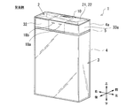
- FIG. 1 is a schematic configuration diagram of a package according to the first embodiment.
- FIG. 2 is a schematic configuration diagram of a package according to the first embodiment.
- FIG. 3 is a diagram illustrating a state in which the package according to the first embodiment is opened.
- FIG. 4 is an exploded view of the sealing seal according to the first embodiment.
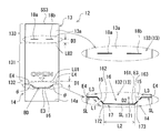
- FIG. 5 is a top view of the upper seal portion of the seal seal according to the first embodiment.
- FIG. 6 is a view illustrating a back surface of a first upper layer seal portion of the seal seal according to the first embodiment.
- FIG. 7A is a diagram illustrating a situation in which the first upper layer seal portion is turned off from the lower layer seal portion in the seal seal according to the first embodiment.
- FIG. 7B is a diagram illustrating a state in which the first upper layer seal portion is turned off from the lower layer seal portion in the seal seal according to the first embodiment.
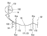
- FIG. 8A is a diagram showing a sheet material for forming a sealing seal having specifications for forming tab base end edges on both sides of a tab for picking.
- FIG. 8B is a diagram illustrating a sheet material for forming a sealing seal having specifications that do not form tab base edge portions on both sides of a tab for picking.
- FIG. 9A shows a modification of the tab for picking in the seal.
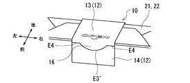
- FIG. 9B shows a modification of the tab for picking in the seal.
- FIG. 9C shows a modification of the tab for picking in the seal.
- FIG. 1 is an external perspective view of the front side of the package 1.
- FIG. 2 is an external perspective view of the back side of the package 1.
- the package 1 is a package having a box shape for packaging a plurality of cigarettes.
- the package 1 is formed by including an inner packaging box 2 that directly wraps a cigarette and an outer packaging box 3 that wraps the inner packaging box 2 except for the upper closing surface 21 of the inner packaging box 2. Or it is called a soft pack.
- the inner packaging box 2 is made of inner paper whose outer surface is coated with an aluminum foil, for example, and the bottom surface and the upper closing surface 21 form a mouth fold portion 22 by folding the inner paper.
- the outer packaging box 3 is made of an outer packaging paper having a pattern, a product name, etc. printed on the outer surface thereof, and the inner packaging box 2 covers the side and bottom surfaces of the inner packaging box 2 with the upper closing surface 21 exposed. 2 is packaged. Similarly to the upper closing surface 21 of the inner packaging box 2, the bottom surface of the outer packaging box 3 forms a fold-folded portion 22 by folding a part of the outer packaging paper.
- reference numeral 31 indicates the front surface of the outer packaging box 3
- reference numeral 32 indicates the rear surface of the outer packaging box 3.
- Reference numeral 33 a indicates the left side surface of the outer packaging box 3
- reference numeral 33 b indicates the right side surface of the outer packaging box 3.
- the front surface 31 and the rear surface 32 of the outer packaging box 3 are parallel to each other and are orthogonal to the upper closing surface 21 of the inner packaging box 2.
- the upper closing surface 21 of the inner packaging box 2, the front surface 31 of the outer packaging box 3, and the rear surface 32 of the outer packaging box 3 correspond to a first surface, a second surface, and a third surface according to the present invention, respectively.
- the inner packaging box 2 and the outer packaging box 3 in this embodiment correspond to the packaging part in this invention.
- the front side of the package 1 is defined as “front”
- the back side is defined as “rear”.
- the vertical and horizontal directions of the package 1 are defined as shown in FIG.
- the left-right direction of the package 1 is called “width direction”, and the up-down direction is called “height direction”.
- 1 and 2 show the up, down, front, back, left, and right directions.
- the package 1 is sealed by being entirely covered with an exterior film 4 when not opened.
- the exterior film 4 may be a transparent film made of a material such as polypropylene, cellophane, or polyethylene terephthalate.
- the exterior film 4 is provided with an opening tape (also referred to as “tea tape”) 5.
- the opening tape 5 is a band member wound around the package 1 so as to circulate along the circumferential surface, and is attached to the back surface (inner surface) side of the exterior film 4.
- the opening tape 5 is used to tear and open the exterior film 4 by pulling a tip (not shown) by a user (smoker) when opening the package 1.
- FIG. 3 is a diagram illustrating a state in which the package 1 is opened.
- FIG. 3 shows a state where the exterior film 4 is torn from the opening tape 5 and the upper portion 4a of the exterior film 4 is removed.
- the upper closed surface 21 (mouth folded portion 22) of the inner packaging box 2 in the package 1 is exposed to the outside.
- Numeral 10 shown in FIGS. 1 to 3 is a sealing seal.
- the sealing seal 10 has a band shape, and is bonded so as to straddle the upper closing surface 21 (mouth folded portion 22) of the inner packaging box 2 and the front surface 31 and the rear surface 32 of the outer packaging box 3.
- the sealing seal 10 traverses the center in the width direction of the upper closing surface 21 (mouth folded portion 22) of the inner packaging box 2, and both ends thereof are bent vertically toward the front surface 31 and the rear surface 32 of the outer packaging box 3.
- the sealing seal 10 seals the upper closing surface 21 (mouth folded portion 22) of the package 1.
- the sealing seal 10 is left in the mouth folded portion 22 formed on the upper closing surface 21 of the inner packaging box 2, One side of the folding part 22 is cut off to form a cigarette outlet. Thereby, the cigarette packaged in the inner packaging box 2 of the package 1 is exposed from the takeout port, and the cigarette can be taken out.
- FIG. 4 is an exploded view of the sealing seal 10 according to the first embodiment.
- the seal seal 10 has a lower layer seal part 11 bonded to the package 1 and an upper layer seal part 12 laminated on the lower layer seal part 11 and adhered to the lower layer seal part.
- the upper layer seal portion 12 includes a first upper layer seal portion 13 and a second upper layer seal portion 14.
- the lower layer sealing part 11 is a strip having a rectangular shape, and the broken line indicates the folding position.
- Reference sign LB1 shown in FIG. 4 is a first folding line that is folded at a first edge E1 located at the boundary between the front surface 31 of the outer packaging box 3 and the upper closing surface 21 (mouth folding portion 22) of the inner packaging box 2.
- Symbol LB2 is a second folding line that is folded at the second edge E2 located at the boundary between the rear surface 32 of the outer packaging box 3 and the upper closing surface 21 (mouth folding portion 22) of the inner packaging box 2.
- a rectangular region between the first fold line LB1 and the second fold line LB2 is referred to as a lower layer first region 111, and a rectangle between one short side SS1 and the first fold line LB1.
- the region is referred to as a lower layer second region 112, and the rectangular region between the second folding line LB2 and the other short side SS2 is referred to as a lower layer third region 113.
- the lower layer second region 112 of the lower layer sealing part 11 is bonded to the front surface 31 of the outer packaging box 3, and the lower layer first region 111 is bonded to the upper closing surface 21 (mouth folded portion 22) of the inner packaging box 2,
- the region 113 is bonded to the rear surface 32 of the outer packaging box 3. That is, as shown in FIG. 3, the lower layer sealing seal 11 extends over the front surface 31 of the outer packaging box 3, the upper closing surface 21 (mouth fold portion 22) of the inner packaging box 2, and the rear surface 32 of the outer packaging box 3. Bonded to the package 1.
- FIG. 4 is a top view of the upper seal portion 12 of the sealing seal 10 according to the first embodiment.
- Reference numeral 13 a indicates the upper surface of the first upper layer seal portion 13.
- Reference numeral 14 a indicates an upper surface of the second upper layer seal portion 14.
- the upper layer seal portion 12 is a paper strip having a rectangular shape as a whole, and a broken line indicates a folding position.
- the symbol LU2 is a second folding line that is folded at the second edge E2 of the package 1.
- a rectangular region between the first fold line LU1 and the second fold line LU2 is referred to as an upper layer first region 131
- the second upper layer seal portion 14 in the first upper layer seal portion 13 The area between the boundary BD and the first fold line LU1 is called an upper second area 132, and the rectangular area between the second fold line LU2 and the short side SS3 is called an upper third area 133.
- first upper layer seal portion 13 and the second upper layer seal portion 14 in the upper layer seal portion 12 are locally connected via an easy-cut portion 15 as shown in the enlarged view of FIG.
- the easy-cut portion 15 is also called nick stop, and can be separated from the first upper layer seal portion 13 and the second upper layer seal portion 14 by being cut (broken) by an external force.
- a slit SL is formed in the boundary portion BD between the first upper layer seal portion 13 and the second upper layer seal portion 14 except for a portion where the easy-cut portion 15 is formed.
- the distance between the first fold line LU1 and the second fold line LU2 in the first upper layer seal portion 13 is the same as the first fold line LB1 in the lower layer seal portion 11. It is the same as the distance from the second folding line LB2 (the length of the lower first region 111), and matches the depth of the package 1 (upper closing surface 21).
- the first upper layer seal portion 13 may be folded with a slight margin as compared with the lower layer seal portion 11, so that the first fold line LU1 in the first upper layer seal portion 13 and
- the distance between the second fold line LU2 (the length dimension of the upper layer first area 131) is the distance between the first fold line LB1 and the second fold line LB2 (lower layer first area 111 of the lower layer first area 111). It may be set slightly larger than the length dimension).
- the upper first region 131 in the first upper seal portion 13 is laminated on the lower first region 111 of the lower seal seal portion 11 and is glued (adhered) to the lower first region 111.
- the upper second region 132 in the first upper seal part 13 is laminated on the lower second region 112 in the lower seal part 11 and is glued to the lower second region 112.
- the upper third region 133 in the first upper seal portion 13 is laminated on the lower third region 113 in the lower seal portion 11 and is glued to the lower third region 113.
- the separation dimension between the boundary portion BD and the first folding line LU1 in the first upper layer seal portion 13 is the short side SS1 in the lower layer sealing seal portion 11 and the first folding line. It is smaller than the distance from LB1 (the length of the lower layer second region 112). Therefore, the upper second region 132 of the first upper seal part 13 is adhered to the lower second region 112 so as to cover a part of the lower second region 112 of the lower seal part 11.
- the second upper layer seal portion 14 is defined as the second upper layer seal portion 14.
- the entire lower layer second region 112 of the lower layer sealing portion 11 is laminated so that the entire uncovered region (all) is covered by the second upper layer sealing portion 14.
- the distance between the short side SS3 and the second folding line LU2 in the first upper layer seal portion 13 is the short side SS2 and the second folding line LB2 in the lower layer sealing seal portion 11. Is equal to the separation dimension (the length dimension of the lower third region 113).
- the first upper layer seal portion 13 may be folded with a slight margin as compared to the lower layer seal portion 11, so that the separation dimension (upper layer) between SS3 and the second fold line LU2
- the length dimension of the third region 133) may be set slightly larger than the distance between the short side SS2 and the second folding line LB2 (the length dimension of the lower layer third region 113) in the lower layer sealing part 11. is there.
- the tab 16 for picking is provided in the front-end
- the tab 16 for knobs is a knob that protrudes from other parts so that the upper layer seal part 12 (first upper layer seal part 13) is peeled from the lower layer seal part 11 so that the user (smoker) can easily pick it.
- the tab 16 for picking is protruded from the front-end
- the tab 16 for picking has a trapezoidal shape, and the shape is defined by the tab upper side 161, the tab first oblique side 162, and the tab second oblique side 163.
- the tab upper side 161 of the tab 16 for picking is parallel to the first folding line LU1, and the tab first oblique side 162 and the tab second oblique side 163 are inclined with respect to the tab upper side 161.
- the tab 16 for picking of the first upper layer seal portion 13 is locally connected to the second upper layer seal portion 14 via the easy-cut portion 15.
- the tab 16 for picking is received on the boundary portion BD side in the second upper layer seal portion 14.
- a trapezoidal recess 17 is formed.
- the shape of the concave portion 17 is defined by a concave upper side 171, a concave first oblique side 172, and a concave second oblique side 173.
- the concave upper side 171, the concave first oblique side 172, and the concave second oblique side 173 of the concave portion 17 are arranged to face the tab upper side 161, the tab first oblique side 162, and the tab second oblique side 163 of the knob tab 16, respectively.
- the easy-cutting portion 15 locally connects the tab first oblique side 162 and the tab second oblique side 163 of the tab 16 for picking with the concave portion first oblique side 172 and the concave second oblique side 173 facing the concave portion 17. ing. As shown in FIG.
- the easy-to-cut portion 15 extends along an oblique direction with respect to the first fold line LU ⁇ b> 1 in the first upper layer seal portion 13.
- one easy cutting portion 15 is provided on each of the tab first oblique side 162 and the tab second oblique side 163 of the tab 16 for picking, but the number is not particularly limited.
- a plurality of easy-cut sections 15 may be provided on each of the tab first oblique side 162 and the tab second oblique side 163.
- the easy-cut portion 15 may be provided only on one of the tab first oblique side 162 and the tab second oblique side 163.
- interposed into slit SL among the boundary parts BD of the 1st upper layer seal part 13 and the 2nd upper layer seal part 14 is formed as the easily cut part 15
- the easy cutting part 15 may be formed by performing a half-cut process along.
- the details of the upper third region 133 in the first upper seal part 13 will be described.
- a pair of slits 18a and 18b are provided in the vicinity of the second folding line LU2.
- the slits 18a and 18b penetrate the upper third region 133 in the first upper seal portion 13 in the thickness direction.
- the slits 18a and 18b extend in parallel with the second fold line LU2.
- two slits 18a and 18b are provided in the upper third region 133, but the number of the slits is not particularly limited.
- the sealing seal 10 in the present embodiment is bonded to the lower sealing seal part 11 so that the upper sealing part 12 (the first upper sealing part 13 and the second upper sealing part 14) can be peeled off by stopping the adhesive glue. is doing.
- the tab 16 for picking the upper layer second region 132 in the first upper layer seal portion 13 is not adhered to the lower layer second region 112 of the lower layer seal portion 11.
- FIG. 6 is a view showing the back surface 13b of the first upper layer seal portion 13 of the seal seal 10 according to the first embodiment.
- the back surface 13 b of the first upper layer seal portion 13 is an adhesive surface that is bonded to the upper surface of the lower layer seal portion 11.
- an information code (not shown) in which information relating to the campaign, URL for accessing the campaign site, and information on the e-mail address is encoded is printed.
- the information code is preferably printed on the back surface 13 b corresponding to the upper layer first region 131 having the largest area in the first upper layer seal portion 13.
- the information code may be a QR code (registered trademark) which is a kind of two-dimensional code, for example. Further, instead of the two-dimensional code, a one-dimensional barcode may be printed on the back surface 13b of the first upper layer seal portion 13.
- the sealing seal 10 (lower sealing seal portion 11) straddles the front surface 31 of the outer packaging box 3, the upper closing surface 21 (mouth fold portion 22) of the inner packaging box 2, and the rear surface 32 of the outer packaging box 3. In this way, they are bonded.
- the sealing seal 10 of the package 1 in the present embodiment since the tab 16 for picking is provided at the distal end portion of the upper second region 132 in the first upper seal portion 13, the user (smoker) is for picking.
- the package 1 provided with the sealing seal 10 in the present embodiment can be manufactured only by customizing the current package packaging machine, and product information can be added without investing a large amount of machinery and equipment. This is a very useful tool.
- the package 1 can be manufactured by replacing the normal sealing seal with the sealing seal 10 according to the present embodiment, it is possible to suppress a decrease in the manufacturing efficiency of the package 1 by the packaging machine.
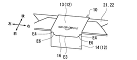
- the tab 16 for picking in the first upper layer seal portion 13 is formed with a straight picking edge E3 by the tab upper side 161, the finger of the user (smoker) is picked up by the tab 16 for picking (the knob).
- the edge portion E3) makes it easier to catch, and the first upper layer seal portion 13 can be more easily peeled off from the lower layer seal portion 11.
- a trapezoidal shape can be preferably exemplified.
- the lower layer second region 112 of the lower layer sealing part 11 is bent in the orthogonal direction from the lower layer first region 111 with the first edge E1 as a boundary, and is adhered to the front surface 31 of the outer packaging box 3.
- the upper second region 132 of the first upper seal portion 13 is folded in the orthogonal direction from the upper first region 131 along the lower second region 112 of the lower seal seal portion 11 with the first edge E1 as a boundary. ing.
- the upper second region 132 of the first upper seal portion 13 is folded in the orthogonal direction from the upper first region 131, so that the upper second region 132 of the first upper seal portion 13 becomes the lower seal seal portion 11.
- Restoring force can be applied in the direction of peeling from the lower layer second region 112.
- the tab 16 for picking is provided so as to protrude from the tip of the upper second region 132 in the first upper seal portion 13 in the opposite direction (opposite side) to the first edge E1. Therefore, the direction in which the tab 16 for picking up the first upper layer seal portion 13 is picked up and the direction of the restoring force acting on the upper second region 132 of the first upper layer seal portion 13 coincide with each other, making it easier to lower the lower layer.
- the first upper layer seal portion 13 can be peeled off from the seal seal portion 11.
- the tab 16 for picking is provided close to the first edge E1 of the package 1. Therefore, the restoring force of the upper second region 132 acting in the direction of turning up the tab 16 for picking can be further increased.
- the base portion of the tab 16 for picking that is, the separation distance between the tab base edge E4 and the first edge E1 (first folding line LU1) (hereinafter referred to as “first separation distance”) D1 ( 5) is preferably in the range of 0 mm to 4 mm, more preferably in the range of 0 mm to 3 mm, and particularly preferably in the range of 0 mm to 2 mm.
- the paper repulsive force for easily turning the first upper layer seal portion 13 may not be obtained.
- a preferable repulsive force is obtained in the upper second region 132 of the first upper seal portion 13 by setting the first separation distance D1 to 4 mm or less, and a more preferable repulsion by setting the first separation distance D1 to 3 mm or less. Power is obtained.
- the first separation distance D1 is set to 2 mm or less, the first upper layer seal portion 13 is optimally turned.
- the lower layer sealing seal portion 11 A By adjusting the first separation distance D1 between the tab base end edge portion E4 and the first edge portion E1 (first folding line LU1) located at the base of the tab 16 for picking to the above range, the lower layer sealing seal portion 11 A sufficient amount of restoring force acting in the direction of peeling the upper second region 132 of the first upper layer seal portion 13 from the lower second region 112 can be obtained, and the ease of peeling off the first upper layer seal portion 13 can be improved. Can be improved.
- the nick length L1 is 0.3 mm. If it falls below, the nick part may be cut off during the manufacture, and if the nick length L1 exceeds 0.7 mm, an undesired part (other than the nick) when the user picks the package 1 after manufacturing the package 1 There is a risk that the paper will be cut at the part. Therefore, the nick length L1 is preferably set in the range of 0.3 to 0.7 mm, and is optimally set to 0.5 mm.
- the separation distance D2 (refer to a partially enlarged view of FIG. 5) between the tab edge E3 and the tab base end edge E4 in the tab 16 for picking exceeds 3 mm.
- the second separation distance D2 is preferably in the range of 1 mm to 3 mm.
- the picking tab tip width L2 is: It is preferable to set to a dimension of 5 mm or more from the viewpoint of easy picking of the picking edge E3.
- tab tab base width for picking the width of the tab base edge E4 of the tab 16 for picking (hereinafter referred to as “tab tab base width for picking”) L3 (see the partially enlarged view of FIG. 5).
- the tab base end width L3 for each tab base end edge E4 formed on both sides of the tab 16 for picking is set to a width of 1 mm or more from the viewpoint of allowing an accuracy error in manufacturing the sealing seal 10. Is preferred.
- FIG. 8A is a view showing the sheet material S1 for forming the sealing seal 10 having specifications for forming the tab base edge E4 on both sides of the tab 16 for picking.
- FIG. 8A is a view showing the sheet material S1 for forming the sealing seal 10 having specifications for forming the tab base edge E4 on both sides of the tab 16 for picking.
- FIG. 8B is a view showing a sheet material S2 for forming the sealing seal 10 having a specification in which the tab base edge E4 is not formed on both sides of the tab 16 for picking.
- symbol CLp shown in FIG. 8A, 8B shows a design cutting line
- symbol CLa shows an actual cutting position.
- the sheet materials S1, S2 are separated into individual sealing seals 10 by being cut along the design cutting line CLp in the manufacturing process.
- the tab base end edge E4 is not formed on both sides of the tab 16 for picking, and the tab base end width L3 for picking is zero. Therefore, when the actual cutting position CLa deviates from the design cutting line CLp, the shape of the one end side and the other end side in the width direction of the sealing seal 10 is different in the sealing seal 10 cut out from the sheet material S2. It will stand out. That is, an error in the cutting position of the sealing seal 10 in the manufacturing process is not allowed, and the sealing seal 10 cannot be used as a product and may be discarded. Although there is no particular demerit in increasing the tab base end width L3 for the tab base end edge E4, it is preferable to determine it in relation to the overall width dimension of the sealing seal 10, the tab tab end width L2, etc.
- the angle formed by the tab first oblique side 162 (tab second oblique side 163) connecting the tab edge E3 and the tab base end edge E4 in the tab 16 and the tab edge E3 (hereinafter, “ It is preferable that ⁇ (refer to FIG. 5) ⁇ (referred to as “slope side inclination angle”) be 90 ° or more.
- the upper limit angle of the hypotenuse inclination angle ⁇ in the tab 16 for picking is appropriately determined based on the respective dimensions such as the full width of the sealing seal 10, the tip tab width L2, the tab base end width L3, the second separation distance D2, and the like. It only has to be calculated.
- 20 mm is often adopted as a standard. Therefore, the total width of the sealing seal 10 is 20 mm, the tab tab width L2 is 5 mm, the tab base end width L3 of each tab base edge E4 on both sides of the tab 16 is 1 mm, and the second separation distance D2 is When set to 2 mm, the hypotenuse inclination angle ⁇ of the tab 16 for picking is approximately 163 °.
- the hypotenuse inclination angle ⁇ of the tab 16 for picking may be set in a range of 90 ° or more and 163 ° or less, and by setting in such a range, it is difficult to tear the tab 16 for picking and ease of picking. Balance can be achieved.
- the hypotenuse inclination angle ⁇ of the tab 16 for picking is set in the range of 105 ° or more and 163 ° or less.
- the hypotenuse inclination angle ⁇ of the tab 16 for picking is in the range of 130 ° to 140 ° (in the range of 135 ⁇ 5 °), and the balance between the difficulty of tearing the tab 16 and the ease of picking is particularly excellent.
- the full width of the sealing seal 10 is not limited to 20 mm.
- the tab 16 for picking of the first upper layer sealing portion 13 is not bonded to the lower sealing seal portion 11, and the second upper layer seal adjacent to the tab 16 for picking is used.
- the tab 16 for picking is locally connected to the portion 14 via the easy cutting portion 15. According to this, the easy cutting part 15 can be easily cut by picking and pulling the tab 16 for picking, and the second upper seal part 14 is maintained in a state where it is adhered to the lower seal seal part 11.
- the first upper seal part 13 can be easily peeled off from the lower seal part 11.
- the tab 16 for picking in the first upper layer seal portion 13 has a trapezoidal shape, and is complementary to the tab 16 for picking on the distal end side of the second upper layer seal portion 14.
- the trapezoidal concave portion 17 By forming the trapezoidal concave portion 17, the tab first oblique side 162 and the tab second oblique side 163 of the tab 16 for picking and the concave portion first oblique side 172 and the concave second oblique side 173 on the concave portion 17 side facing these can be easily formed. It was made to connect by the cutting part 15.
- sticker part 13 can be extended along the diagonal direction with respect to the 1st edge E1.
- the component force of the tensile force that acts when the tab 16 for picking is picked up acts in the direction of tearing the easy-cutting portion 15.
- the portion 15 can be suitably cut off, and the portion of the first upper layer seal portion 13 other than the easily cut portion 15, for example, the region where the information code is printed on the back surface 13 b can be suppressed from being cut off.
- the tab 16 for picking is picked up, only the easy cutting part 15 can be cut
- the slits 18a and 18b are provided in the upper third region 133 in the first upper seal portion 13, the upper third region 133 in the first upper seal portion 13 and The repulsive force of the paper by sticking the lower layer third region 113 of the lower layer sealing part 11 can be suppressed, and the folding can be made smooth. Moreover, the tension
- the slits 18a and 18b in the upper third region 133 of the first upper seal portion 13 are preferably provided in the vicinity of the second folding line LU2 (second edge E2).
- the slits 18a and 18b may be formed in the upper first region 131 of the first upper seal part 13 as long as the slits 18a and 18b are in the vicinity of the second fold line LU2 (second edge E2). 11, the repulsive force of the paper by sticking the 1st upper layer seal
- a separation distance (hereinafter referred to as “third separation distance”) D3 (refer to FIG. 5) from the second folding line LU2 (second edge E2) to the slits 18a and 18b in the first upper layer seal portion 13 is as follows. It is preferable to set in the range of 0 mm or more and 5 mm or less.
- the third separation distance D3 is smaller, the effect of reducing the repulsive force of the paper by bonding the upper third region 133 in the first upper seal portion 13 and the lower third region 113 in the lower seal seal portion 11 together. Can be increased.
- the repulsive force of the paper can be suitably reduced.
- the 3rd separation distance D3 is 0 mm, the case where slit 18a, 18b is formed on 2nd folding line LU2 in the 1st upper layer seal
- the third separation distance D3 is smaller, the effect of reducing the repulsive force of the paper can be increased as described above.
- the consumer picks the tab 16 for picking and turns the first upper layer seal portion 13.
- the first upper seal portion 13 can be easily broken at the positions of the slits 18a and 18b. Therefore, the effect of reducing the repulsive force of the paper due to the bonding of the upper third region 133 in the first upper seal portion 13 and the lower third region 113 of the lower seal seal portion 11, and the user can reduce the first upper seal portion 13.
- the slits 18a and 18b may be provided on the upper surface side (upper layer first region 131) of the package 1 or may be provided on the rear surface side (upper layer third region 133) of the package 1.
- the slits 18a and 18b may be provided on the back side (upper third region 133) of the package 1 as in the present embodiment, it is difficult for consumers to notice the presence of the slits 18a and 18b on the appearance of the package 1. There is an advantage that you can.
- the slits 18a and 18b extend in parallel with the second folding line LU2, a repulsive force (restoring force) due to folding of the upper third region 133 in the first upper seal portion 13 is achieved. ) Can be more suitably relaxed.
- the inner packaging box 2 and the outer packaging box 3 are sealed by being covered with the exterior film 4, and are sealed above the opening tape 5 provided on the exterior film 4.
- sticker 10 was arrange
- the sealing seal 10 and the package 1 according to the embodiment can be variously changed, improved, combined, and the like.
- the shape of the tab 16 for picking in the sealing seal 10 is a trapezoid, but other shapes may be adopted.
- 9A to 9C show modified examples of the tab 16 for picking in the sealing seal 10.
- the tab 16 for picking has a rectangular shape, not a trapezoidal shape.
- the tab edge E3 and the tab base end edge E4 are connected by a vertical edge E5 orthogonal thereto.
- FIG. 9A shows the shape of the tab 16 for picking in the sealing seal 10.
- the tab 16 for picking has an arc-shaped tab edge E3 ′, and tab base edge portions E4 are respectively connected to both ends of the tab edge E3 ′. Further, in the example shown in FIG. 9C, the linear knob edge E3 and the tab base end edge E4 are connected via an arcuate arc edge E6.
- the lower seal seal part 11 and the upper seal part 12 in the seal seal 10 have been described as an example, but the lower seal seal part 11 and the upper seal part 12 are made of a polymer material. good. Examples of the polymer material for forming the sealing seal 10 include PE (polyethylene), PP (polypropylene), and PET (polyethylene terephthalate).
- the sealing seal 10 may be formed of the above-mentioned polymer material and paper bonding paper or metal foil and paper bonding paper.
- attachment of the lower seal seal part 11 and the upper seal part 12 in the seal seal 10 may use, for example, an ethylene vinyl acetate resin system as a main material.
- an ethylene vinyl acetate resin-based paste from the viewpoint of ease of peeling of the upper seal portion 12 with respect to the lower seal seal portion 11 and suppression of undesired peeling
- the present invention is not limited to this.
- the packaging object is not particularly limited.
- the other packaging objects in the package 1 may be cigars or cigarillos, or may be smokeless cigarettes such as snus or electronic cigarettes.
- the present invention is not limited to the tobacco product as described above, and a packaging object that is not a tobacco product may be packaged by the package 1.
Landscapes
- Engineering & Computer Science (AREA)
- Mechanical Engineering (AREA)
- Packages (AREA)
- Packaging Of Annular Or Rod-Shaped Articles, Wearing Apparel, Cassettes, Or The Like (AREA)
- Cartons (AREA)
Abstract
従来に比べて下層シール部から上層シール部を剥離し易い2重封緘シールおよびそれを備えたパッケージを提供する。パッケージは、包装対象物を包装する包装部と、包装部に取り付けられた2重封緘シールと、を備え、2重封緘シールは、包装部に接着される下層封緘シール部と、下層封緘シール部上に積層されると共に下層封緘シール部に接着される第1上層シール部と、第1上層シール部に設けられた摘み用タブと、を有する。
Description
本発明は、2重封緘シールおよびパッケージに関する。
シガレット等のたばこ商品は、通常、所定の本数毎に包装体に包装されている。このような包装体として、アルミ箔加工紙等の内包紙と、この内包紙を覆う外包紙によって形成されたものがよく知られており、所謂個装と呼ばれている。外包紙として、ソフトパック又はソフトパッケージと呼ばれる薄紙で形成されたものや、ハードパック、ハードパッケージ又はボックスと呼ばれる、板紙を箱型に組み立てて形成されたものが知られている。
通常、シガレットのソフトパッケージは、複数本のシガレットを内包紙により包装し、更にこの内包紙の側面および底面を外包紙で包装している。そして、内包紙を互いに折り込んで形成した口折り部と外包紙との一部を跨ぐように封緘紙が糊付けされている。シガレットを取り出す場合には、封緘紙の両側に形成された口折り部のどちらか一方の内包紙を欠切し、取り出し口(開口部)を形成することでシガレットを取り出すことができる。
ここで、封緘紙を2重に積層したソフトパッケージが知られている(例えば、特許文献1を参照)。特許文献1に示されるパッケージは、口折り部と外包紙との一部を跨ぐように糊付けされた第1の封緘紙上に第2の封かん紙が積層されており、着離性を有する粘着剤によって第2の封緘紙が第1の封かん紙に対して着離可能に糊付けされている。このパッケージによれば、口折り部との一部にシガレットの取り出しのための開口部を形成した後、第1の封かん紙上に着離可能に糊付けされている第2の封かん紙を剥ぎ取り、この第2の封かん紙で開口部を覆うことができ、開口部からのシガレットの脱落や、パッケージ内のシガレットの防湿および香料の気散防止等を図ることができる。
しかしながら、従来における2重封緘紙(シール)は、下層部分から上層部分を剥ぎ取り難いという課題があった。
本発明は、このような実情に鑑みてなされたものであって、従来に比べて下層シール部から上層シール部を剥離し易い2重封緘シールおよびそれを備えたパッケージを提供することを目的とする。
本発明では、上記課題を解決するために、包装部に取り付けられた2重封緘シールの上層シール部に、包装部に接着される下層封緘シール部から上層シール部を剥離する際に摘むための摘み用タブを設けるようにした。
より詳しくは、本発明に係るパッケージは、包装対象物を包装する包装部と、前記包装部に取り付けられた2重封緘シールと、を備え、前記2重封緘シールは、前記包装部に接着される下層封緘シール部と、前記下層封緘シール部上に積層されると共に当該下層封緘シール部に接着される上層シール部と、前記上層シール部に設けられた摘み用タブと、を有することを特徴とする。
また、本発明は、包装対象物を包装する包装部に取り付けられる2重封緘シールであって、前記包装部に接着される下層封緘シール部と、前記下層封緘シール部上に積層されると共に当該下層封緘シール部に接着される上層シール部と、前記上層シール部に設けられた摘み用タブと、を有することを特徴とする。
本発明によれば、2重封緘シールの上層シール部に摘み用タブを設けるようにしたので、摘み用タブを起点として、包装部に接着される下層封緘シール部から上層シール部を容易に剥離することができる。
また、本発明に係る2重封緘シールにおいて、前記摘み用タブは直線状の摘み用縁部を有していても良い。
また、本発明に係る2重封緘シールにおいて、前記摘み用タブは台形状を有していても良い。
また、本発明に係るパッケージにおいて、前記包装部は箱形状を有すると共に、互いに直交する第1面と第2面とを含んで構成されており、前記下層封緘シール部は、前記第1面に接着される下層第1領域と前記第2面に接着される下層第2領域とを有する帯体であると共に、前記第1面および前記第2面に跨るようにして前記包装部に接着され、前記上層シール部は、前記下層第1領域に積層される上層第1領域と前記下層第2領域に積層される上層第2領域とを有し、前記上層第2領域は、前記第1面および前記第2面の間に位置する第1縁部を境に前記下層第2領域に沿うように前記上層第1領域から直交方向に折り曲げられており、前記摘み用タブは、前記上層第2領域の先端側から前記第1縁部と逆方向に向かって突設されていても良い。
また、2重封緘シールにおいて、前記摘み用タブは、前記第1縁部に近設されていても良い。その場合、前記第1上層シール部において前記摘み用タブの根元に形成される直線状のタブ基端縁部と前記第1縁部とが離間する第1離間距離は、0mm以上4mm以下の範囲に設定されていても良い。また、前記摘み用タブの先端側に形成された直線状の摘み用縁部と前記タブ基端縁部とが離間する第2離間距離は、1mm以上3mm以下の範囲に設定されていても良い。
また、2重封緘シールにおいて、前記上層シール部における前記上層第2領域は、前記下層封緘シール部における前記下層第2領域の一部を覆い、前記下層第2領域のうち、前記上層第2領域によって覆われていない非被覆領域の少なくとも一部には、前記摘み用タブが形成されている前記上層シール部の先端部に隣接するように第2上層シール部が前記下層第2領域に接着されており、前記上層第2領域の前記摘み用タブは前記下層第2領域に対して非接着状態であると共に、前記摘み用タブと前記第2上層シール部とが易切断部を介して局所的に連結されており、前記摘み用タブを介して前記上層シール部が前記下層封緘シール部から剥離される際に、前記易切断部が切断されることによって前記第2上層シール部が前記下層封緘シール部と接着された状態に維持されても良い。
ここで、2重封緘シールにおいて、前記易切断部は、前記第1縁部に対して斜め方向又は垂直方向に沿って延在していても良い。
また、2重封緘シールにおいて、前記摘み用タブは台形状を有し、前記第2上層シール部における前記上層シール部の先端側との境界部には、前記摘み用タブを収容する台形状の凹部が形成されており、前記易切断部は、前記摘み用タブの斜辺と当該他部の斜辺と対向する前記凹部側の斜辺を局所的に連結していても良い。
また、2重封緘シールにおいて、前記第2上層シール部は、前記下層第2領域における前記非被覆領域の全体を覆うように当該前記非被覆領域に積層されていても良い。
また、2重封緘シールにおいて、前記包装部は、前記第1面と直交すると共に前記第2面と平行な第3面を含み、前記下層封緘シール部は、前記第3面に接着される下層第3領域を更に有すると共に、前記第1面、前記第2面および前記第3面に跨るようにして前記包装部に接着され、前記上層シール部は、前記下層第3領域に積層される上層第3領域を更に有し、前記上層第3領域に、スリットが設けられていても良い。
また、2重封緘シールにおいて、前記上層第3領域における前記スリットは、前記第1面および前記第3面の間に位置する第2縁部と平行に延設されていても良い。
また、2重封緘シールにおいて、前記上層第3領域における前記スリットは、前記第2縁部に近設されていても良い。
また、本発明に係るパッケージにおいて、前記包装部は外装フィルムによって密封されており、前記外装フィルムには、前記包装部を周回するように当該包装部に巻き掛けられた開封テープが設けられており、前記開封テープよりも上方に前記摘み用タブが配置されていても良い。
また、本発明に係るパッケージにおいて、前記包装部にたばこ商品が包装されていても良い。
なお、本発明における課題を解決するための手段は、可能な限り組み合わせて採用することができる。
本発明によれば、従来に比べて下層シール部から上層シール部を剥離し易い2重封緘シールおよびそれを備えたパッケージを提供することができる。
ここで、本発明に係る2重封緘シールおよびパッケージの実施形態について、図面に基づいて説明する。また、本実施形態に記載されている構成要素の寸法、材質、形状、その相対配置等は、特に特定的な記載がない限りは、発明の技術的範囲をそれらのみに限定する趣旨のものではない。
<実施形態1>
図1および図2は、実施形態1に係るパッケージ1の概略構成図である。図1は、パッケージ1の正面側の外観斜視図である。図2は、パッケージ1の背面側の外観斜視図である。パッケージ1は、複数のシガレットを包装する箱形状を有する包装体である。パッケージ1は、シガレットを直接的に包んでいる内包箱2と、この内包箱2の上閉塞面21を除いて内包箱2を包み込む外包箱3を含んで形成されたものであり、所謂ソフトパッケージ又はソフトパックと呼ばれている。
図1および図2は、実施形態1に係るパッケージ1の概略構成図である。図1は、パッケージ1の正面側の外観斜視図である。図2は、パッケージ1の背面側の外観斜視図である。パッケージ1は、複数のシガレットを包装する箱形状を有する包装体である。パッケージ1は、シガレットを直接的に包んでいる内包箱2と、この内包箱2の上閉塞面21を除いて内包箱2を包み込む外包箱3を含んで形成されたものであり、所謂ソフトパッケージ又はソフトパックと呼ばれている。
内包箱2は、例えば外面がアルミ箔でコーティングされた内包紙からなり、その底面および上閉塞面21は、内包紙を折り込むことで口折り部22を形成している。外包箱3は、その外面に模様や商品名等が印刷された外包紙からなり、内包箱2の上閉塞面21を露出させた状態で、内包箱2の側面および底面を覆うように内包箱2を包装している。外包箱3の底面も、内包箱2の上閉塞面21と同様、外包紙の一部を折り込むことで口折り部22を形成している。ここで、符号31は外包箱3の前面を示し、符号32は外包箱3の後面を示す。また、符号33aは外包箱3の左側面を示し、符号33bは外包箱3の右側面を示す。外包箱3の前面31および後面32は互いに平行であり、それぞれ内包箱2の上閉塞面21に対して直交している。本実施形態においては、内包箱2の上閉塞面21、外包箱3の前面31、外包箱3の後面32が、それぞれ本発明に係る第1面、第2面、第3面に相当する。また、本実施形態における内包箱2および外包箱3が本発明における包装部に相当する。以下、本明細書において、パッケージ1の正面側を"前方"と定義し、背面側を"後方"と定義する。また、パッケージ1の上下前後左右の各方向を、図1に示すように定義する。パッケージ1の左右方向を「幅方向」と呼び、上下方向を「高さ方向」と呼ぶ。図1および図2に、上下前後左右の各方向を図示する。
図1および図2に示すように、パッケージ1は、未開封時には外装フィルム4によって全体が覆われていることで密封されている。外装フィルム4は、例えばポリプロピレン、セロファン、ポリエチレンテレフタレート等の材料からなる透明フィルムであっても良い。外装フィルム4には、開封テープ(「テアテープ」とも呼ばれる)5が設けられている。開封テープ5は、パッケージ1の一周面に沿って周回するように巻き掛けられた帯部材であり、外装フィルム4の裏面(内面)側に貼り付けられている。開封テープ5は、パッケージ1の開封時に使用者(喫煙者)によって先端部(図示せず)が引っ張られることにより、外装フィルム4を引き裂いて開封するために用いられる。符号4aは、外装フィルム4のうち、開封テープ5よりも上側、すなわち上閉塞面21(口折り部22)に対して近接する上側部分である。図3は、パッケージ1を開封した状態を示す図である。図3に、開封テープ5を起点として外装フィルム4を引き裂き、外装フィルム4の上側部分4aを取り除いた状態を示す。図3に示す状態では、パッケージ1における内包箱2の上閉塞面21(口折り部22)が外部に露出している。
図1乃至3に示す符号10は、封緘シールである。封緘シール10は、帯形状を有し、内包箱2の上閉塞面21(口折り部22)、外包箱3の前面31および後面32に跨るようにして接着されている。封緘シール10は、内包箱2の上閉塞面21(口折り部22)の幅方向中央を横切り、その両端が外包箱3の前面31および後面32に向けて垂直に折り曲げられている。封緘シール10は、パッケージ1の上閉塞面21(口折り部22)を封緘している。
パッケージ1からシガレットを取り出すには、図3に示すように外装フィルム4を開封した後、内包箱2の上閉塞面21に形成された口折り部22のうち、封緘シール10を残して、口折り部22の片側を切り取って、シガレットの取り出し口を形成する。これにより、パッケージ1における内包箱2に包装されていたシガレットが取り出し口から露出するようになり、シガレットを取り出すことができるようになる。
本実施形態における封緘シール10は、紙製の封緘シールが2重に積層された2重封緘シールである。以下、封緘シール10の詳細構造について説明する。図4は、実施形態1に係る封緘シール10の分解図である。封緘シール10は、パッケージ1に接着される下層封緘シール部11と、下層封緘シール部11上に積層されると共に当該下層封緘シール部に接着される上層シール部12を有する。上層シール部12は、第1上層シール部13および第2上層シール部14を含む。
図4に示すように、下層封緘シール部11は矩形状を有する帯体であり、破線は折り込み位置を示している。図4に示す符号LB1は、外包箱3の前面31と内包箱2の上閉塞面21(口折り部22)との境界に位置する第1縁部E1において折り込まれる第1折り込み線である。符号LB2は、外包箱3の後面32と内包箱2の上閉塞面21(口折り部22)との境界に位置する第2縁部E2において折り込まれる第2折り込み線である。
以下、下層封緘シール部11のうち、第1折り込み線LB1と第2折り込み線LB2の間の矩形領域を下層第1領域111と呼び、一方の短辺SS1と第1折り込み線LB1の間の矩形領域を下層第2領域112と呼び、第2折り込み線LB2と他方の短辺SS2の間の矩形領域を下層第3領域113と呼ぶ。下層封緘シール部11の下層第2領域112は、外包箱3の前面31に接着され、下層第1領域111は内包箱2の上閉塞面21(口折り部22)に接着され、下層第3領域113は外包箱3の後面32に接着される。すなわち、図3に示すように、下層封緘シール部11は、外包箱3の前面31、内包箱2の上閉塞面21(口折り部22)、および外包箱3の後面32に跨るようにしてパッケージ1に接着されている。
次に、封緘シール10の上層シール部12の詳細について説明する。図4に示すように、上層シール部12(第1上層シール部13および第2上層シール部14の組み合わせ)は、全体として下層封緘シール部11と実質的に合同形状となる。図5は、実施形態1に係る封緘シール10の上層シール部12の上面図である。符号13aは、第1上層シール部13の上面を示す。符号14aは、第2上層シール部14の上面を示す。上層シール部12は、全体で矩形状を有する紙製の帯体であり、破線は折り込み位置を示している。第1上層シール部13において、図5に示す符号LU1は、パッケージ1の第1縁部E1において折り込まれる第1折り込み線である。符号LU2は、パッケージ1の第2縁部E2において折り込まれる第2折り込み線である。以下、第1上層シール部13のうち、第1折り込み線LU1と第2折り込み線LU2の間の矩形領域を上層第1領域131と呼び、第1上層シール部13における第2上層シール部14との境界部BDと第1折り込み線LU1の間の領域を上層第2領域132と呼び、第2折り込み線LU2と短辺SS3の間の矩形領域を上層第3領域133と呼ぶ。
ここで、上層シール部12における第1上層シール部13と第2上層シール部14は、図5の拡大図に示されるように易切断部15を介して局所的に連結されている。易切断部15は、所謂ニック止めとも呼ばれ、外力によって切断(破断)されることで第1上層シール部13と第2上層シール部14を分離することができる。第1上層シール部13および第2上層シール部14の境界部BDには、易切断部15が形成される部位を除いてスリットSLが形成されている。
ここで、第1上層シール部13における第1折り込み線LU1と第2折り込み線LU2との離間寸法(上層第1領域131の長さ寸法)は、下層封緘シール部11における第1折り込み線LB1と第2折り込み線LB2との離間寸法(下層第1領域111の長さ寸法)と等しく、パッケージ1(上閉塞面21)の奥行寸法に一致する。但し、紙の厚さの関係上、第1上層シール部13は、下層封緘シール部11に比べて多少の余裕をもって折り込まれることもあるため、第1上層シール部13における第1折り込み線LU1と第2折り込み線LU2との離間寸法(上層第1領域131の長さ寸法)が、下層封緘シール部11における第1折り込み線LB1と第2折り込み線LB2との離間寸法(下層第1領域111の長さ寸法)よりも若干大きく設定される場合もある。そして、第1上層シール部13における上層第1領域131は、下層封緘シール部11の下層第1領域111上に積層されると共に当該下層第1領域111に糊付け(接着)される。また、第1上層シール部13における上層第2領域132は、下層封緘シール部11における下層第2領域112上に積層されると共に当該下層第2領域112に糊付けされる。また、第1上層シール部13における上層第3領域133は、下層封緘シール部11における下層第3領域113上に積層されると共に当該下層第3領域113に糊付けされる。
ここで、第1上層シール部13における境界部BDと第1折り込み線LU1との離間寸法(上層第2領域132の長さ寸法)は、下層封緘シール部11における短辺SS1と第1折り込み線LB1との離間寸法(下層第2領域112の長さ寸法)に比べて小さい。そのため、第1上層シール部13の上層第2領域132は、下層封緘シール部11の下層第2領域112の一部を覆うようにして、下層第2領域112に接着される。本実施形態では、下層封緘シール部11における下層第2領域112のうち、第1上層シール部13の上層第2領域132によって覆われていない非被覆領域の少なくとも一部を第2上層シール部14が覆うようにして下層第2領域112に接着される。図4に示す例では、下層封緘シール部11の下層第2領域112における非被覆領域の全体(全部)を第2上層シール部14が覆うようにして積層されている。なお、第1上層シール部13における短辺SS3と第2折り込み線LU2との離間寸法(上層第3領域133の長さ寸法)は、下層封緘シール部11における短辺SS2と第2折り込み線LB2との離間寸法(下層第3領域113の長さ寸法)と等しい。但し、紙の厚さの関係上、第1上層シール部13は、下層封緘シール部11に比べて多少の余裕をもって折り込まれることもあるため、SS3と第2折り込み線LU2との離間寸法(上層第3領域133の長さ寸法)は、下層封緘シール部11における短辺SS2と第2折り込み線LB2との離間寸法(下層第3領域113の長さ寸法)よりも若干大きく設定される場合もある。
ここで、第1上層シール部13における上層第2領域132のうち、第2上層シール部14との境界部BD側に位置する先端部には、摘み用タブ16が設けられている。摘み用タブ16は、下層封緘シール部11から上層シール部12(第1上層シール部13)を使用者(喫煙者)が剥離する際に摘み易いように他の部位よりも突出した摘みである。摘み用タブ16は、第1上層シール部13における上層第2領域132の先端部から、第1折り込み線LU1と逆方向(反対側)に向かって突設されている。また、摘み用タブ16は台形状を有しており、タブ上辺161、タブ第1斜辺162、タブ第2斜辺163によって、その形状が画定されている。摘み用タブ16のタブ上辺161は、第1折り込み線LU1と平行であり、タブ第1斜辺162およびタブ第2斜辺163はタブ上辺161に対して傾斜している。図5に示すように、上層シール部12は、第1上層シール部13の摘み用タブ16が、易切断部15を介して第2上層シール部14と局所的に連結されている。
ここで、第1上層シール部13における上層第2領域132と第2上層シール部14との関係を詳しく説明すると、第2上層シール部14における境界部BD側には、摘み用タブ16を受け入れる台形状の凹部17が形成されている。凹部17は、凹部上辺171、凹部第1斜辺172、凹部第2斜辺173によって、その形状が画定されている。凹部17の凹部上辺171、凹部第1斜辺172、凹部第2斜辺173は、摘み用タブ16のタブ上辺161、タブ第1斜辺162、タブ第2斜辺163にそれぞれ対向して配置されている。そして、易切断部15は、摘み用タブ16のタブ第1斜辺162およびタブ第2斜辺163とこれらに対向する凹部17側の凹部第1斜辺172および凹部第2斜辺173を局所的に連結している。また、図5に示すように、易切断部15は、第1上層シール部13における第1折り込み線LU1に対して斜め方向に沿って延在している。なお、本実施形態においては、摘み用タブ16のタブ第1斜辺162およびタブ第2斜辺163にそれぞれ易切断部15が1つずつ設けられているが、その数は特に限定されない。例えば、タブ第1斜辺162およびタブ第2斜辺163のそれぞれに、複数個の易切断部15が設けられていても良い。また、タブ第1斜辺162およびタブ第2斜辺163の何れか一方のみに易切断部15が設けられていても良い。また、本実施形態では、第1上層シール部13および第2上層シール部14の境界部BDのうち、スリットSL同士に挟まれる領域を易切断部15として形成しているが、境界部BDに沿ってハーフカット加工を施すことで易切断部15を形成しても良い。
次に、第1上層シール部13における上層第3領域133の詳細について説明する。上層第3領域133には、第2折り込み線LU2の近傍に一対のスリット18a,18bが設けられている。スリット18a,18bは、第1上層シール部13における上層第3領域133を厚さ方向に貫通している。スリット18a,18bは、第2折り込み線LU2と平行に延設されている。本実施形態では、上層第3領域133に2つのスリット18a,18bを設けているが、当該スリットの数は特に限定されない。
図4に示す符号BPは、下層封緘シール部11に対する上層シール部12(第1上層シール部13、第2上層シール部14)の糊付け部位を示している。本実施形態における封緘シール10は、接着糊をポイント止めすることで、下層封緘シール部11に対して上層シール部12(第1上層シール部13、第2上層シール部14)を剥離可能に接着している。図4に示す例では、第1上層シール部13における上層第2領域132の摘み用タブ16が下層封緘シール部11の下層第2領域112に対して非接着状態となっている。
図6は、実施形態1に係る封緘シール10の第1上層シール部13の裏面13bを示す図である。第1上層シール部13の裏面13bは、下層封緘シール部11の上面に接着される接着面である。第1上層シール部13の裏面13bには、例えば、キャンペーンに関する情報や、キャンペーンサイトにアクセスするためのURLや電子メールアドレスの情報をコード化した情報コード(図示せず)が印刷されている。情報コードは、第1上層シール部13のうち、最も面積が大きい上層第1領域131に対応する裏面13bに印刷することが好ましい。情報コードは、例えば2次元コードの一種であるQRコード(登録商標)であっても良い。また、2次元コードの代わりに、1次元バーコードを第1上層シール部13の裏面13bに印刷しても良い。
以上のように構成されるパッケージ1においては、外装フィルム4における開封テープ5の上側部分4aが取り除かれることで、図3に示すようにパッケージ1の封緘シール10および上閉塞面21(口折り部22)が露出する。図3に示すように、封緘シール10(下層封緘シール部11)は、外包箱3の前面31、内包箱2の上閉塞面21(口折り部22)、および外包箱3の後面32に跨るようにして接着されている。本実施形態におけるパッケージ1の封緘シール10によれば、第1上層シール部13における上層第2領域132の先端部に摘み用タブ16が設けられているため、使用者(喫煙者)は摘み用タブ16を摘み、引っ張り上げることで、図7A、図7Bに示すように下層封緘シール部11から第1上層シール部13を容易に剥離することができる。また、本実施形態における封緘シール10を備えたパッケージ1は、現行のパッケージ包装機をカスタマイズするだけで製造することが可能であり、巨額の機械設備投資を掛けずに、製品情報を付加することのできるツールとして有用性が高い。また、通常の封緘シールを本実施形態に係る封緘シール10に置き換えることでパッケージ1を製造することができるため、包装機によるパッケージ1の製造効率が低下することも抑制することができる。
その際、第1上層シール部13における摘み用タブ16は、タブ上辺161によって直線状の摘み用縁部E3が形成されているため、使用者(喫煙者)の指が摘み用タブ16(摘み用縁部E3)により一層引っ掛かり易くなり、下層封緘シール部11から第1上層シール部13をより簡単に剥離できるようになる。上記のような直線状の摘み用縁部E3を有する摘み用タブ16の形状として、台形状を好適に挙げることができる。なお、第1上層シール部13の上層第2領域132における第2上層シール部14との境界部BDにおいて、摘み用タブ16の両側に位置する縁部、すなわち摘み用タブ16の付け根に位置する縁部を「タブ基端縁部E4」と呼ぶ。摘み用縁部E3およびタブ基端縁部E4は、第1上層シール部13における第1折り込み線LU1および第1縁部E1に平行である。
また、本実施形態によれば、下層封緘シール部11の下層第2領域112は、第1縁部E1を境に下層第1領域111から直交方向に折り曲げられて外包箱3の前面31に接着されている。また、第1上層シール部13の上層第2領域132は、第1縁部E1を境として下層封緘シール部11の下層第2領域112に沿うように上層第1領域131から直交方向に折り込まれている。このように、第1上層シール部13の上層第2領域132が、上層第1領域131から直交方向に折り込まれることで、第1上層シール部13の上層第2領域132を下層封緘シール部11の下層第2領域112から剥離する方向に復元力が作用させることができる。その際、摘み用タブ16は、第1上層シール部13における上層第2領域132の先端部から、第1縁部E1と逆方向(反対側)に向かって突設されている。そのため、第1上層シール部13の摘み用タブ16を摘んでめくり上げる方向と、第1上層シール部13の上層第2領域132に作用する復元力の方向とが一致し、より一層容易に下層封緘シール部11から第1上層シール部13を剥離することができる。
特に、本実施形態によれば、摘み用タブ16が、パッケージ1の第1縁部E1に近設されている。そのため、摘み用タブ16をめくり上げる方向に作用する上層第2領域132の復元力をより一層大きくすることができる。ここで、摘み用タブ16の付け根の部分、すなわちタブ基端縁部E4と第1縁部E1(第1折り込み線LU1)との離間寸法距離(以下、「第1離間距離」という)D1(図5を参照)は、0mm以上4mm以下の範囲とすることが好ましく、0mm以上3mm以下の範囲とするとより好ましく、0mm以上2mm以下の範囲とすると特に好ましい。なお、第1離間距離D1が4mmを超えてしまうと、第1上層シール部13をめくり易くするための、紙の反発力が十分に得られない虞がある。そして、第1離間距離D1を4mm以下とすることで第1上層シール部13の上層第2領域132において好ましい反発力が得られ、第1離間距離D1を3mm以下とすることで、より好ましい反発力が得られる。また、第1離間距離D1を2mm以下とすることで、第1上層シール部13をめくるに当たって最適な状態となる。摘み用タブ16の付け根に位置するタブ基端縁部E4および第1縁部E1(第1折り込み線LU1)間の第1離間距離D1を上記範囲に調節することで、下層封緘シール部11の下層第2領域112から第1上層シール部13の上層第2領域132を剥離する方向に作用する復元力の大きさを十分に得ることができ、第1上層シール部13の剥ぎ取り易さを向上させることができる。
次に、易切断部15のニック部分の長さ(以下、「ニック長さ」という)L1(図5の部分拡大図を参照)の好ましい範囲について言及すると、ニック長さL1が0.3mmを下回ると製造途中でニック部分が切れてしまう虞があり、ニック長さL1が0.7mmを超えてしまうとパッケージ1の製造後においてユーザがパッケージ1を摘んだ際に、所望しない部分(ニック以外の部分)で紙が切れてしまう虞がある。そこで、ニック長さL1は0.3~0.7mmの範囲に設定すると好ましく、0.5mmとすると最適である。また、摘み用タブ16における摘み用縁部E3とタブ基端縁部E4との離間距離(以下、「第2離間距離」という)D2(図5の部分拡大図を参照)は3mmを超えると紙の反発力が強くなりタブが勝手に捲れてしまう虞があり、1mmを下回ると摘み用タブ16が摘みにくくなる虞がある。そこで、第2離間距離D2は、1mm以上3mm以下の範囲とすることが好ましい。
ここで、摘み用タブ16における摘み用縁部E3の幅(以下、「摘み用タブ先端幅」という)L2(図5の部分拡大図を参照)について言及すると、摘み用タブ先端幅L2は、摘み用縁部E3の摘み易さの観点から5mm以上の寸法に設定することが好ましい。
次に、摘み用タブ16におけるタブ基端縁部E4の幅(以下、「摘み用タブ基端幅」という)L3(図5の部分拡大図を参照)について言及する。摘み用タブ16の両側に形成される各タブ基端縁部E4の摘み用タブ基端幅L3は、封緘シール10の製造上の精度誤差を許容する観点から、1mm以上の幅に設定することが好ましい。ここで、図8Aは、摘み用タブ16の両側にタブ基端縁部E4を形成する仕様の封緘シール10を形成するためのシート材S1を示す図である。図8Bは、摘み用タブ16の両側にタブ基端縁部E4を形成しない仕様の封緘シール10を形成するためのシート材S2を示す図である。図8A,8B中に示す符号CLpは、設計切断線を示し、符号CLaは実際の切断位置を示す。シート材S1,S2は、製造工程において設計切断線CLpに沿って切断されることで、個々の封緘シール10に分離される。
図8A、8Bには、シート材S1,S2から個々の封緘シール10を切り出す際に、設計切断線CLpからずれた実際の切断位置CLaに沿って切断されてしまった場合を示している。まず、図8Aに示すシート材S1においては、摘み用タブ16の両側にタブ基端縁部E4を形成することで、実際の切断位置CLaが設計切断線CLpから多少ずれてしまったとしても、上述の摘み用タブ基端幅L3が多少設計値と相違するだけで目立たず、製造過程における封緘シール10の切断位置の誤差が許容される。一方、図8Bに示すシート材S2においては、摘み用タブ16の両側にタブ基端縁部E4が形成されず、摘み用タブ基端幅L3が零である。従って、実際の切断位置CLaが設計切断線CLpからずれてしまうと、シート材S2から切り出した後の封緘シール10において、封緘シール10の幅方向における一端側と他端側の形状が相違してしまい、目立ってしまう。すなわち、製造過程における封緘シール10の切断位置の誤差が許容されず、封緘シール10を製品として使用できず、破棄せざるを得ない虞がある。なお、タブ基端縁部E4の摘み用タブ基端幅L3を大きくすることでのデメリットは特に無いが封緘シール10の全幅寸法、摘み用タブ先端幅L2等との関係で決定すると良い。
また、摘み用タブ16における摘み用縁部E3およびタブ基端縁部E4を接続するタブ第1斜辺162(タブ第2斜辺163)と摘み用縁部E3とによって形成される角度(以下、「斜辺傾斜角度」という)θ(図5を参照)は、90°以上とすることが好ましい。摘み用タブ16の斜辺傾斜角度θを90°以上とすることで、易切断部15(ニック止め)箇所を起点として摘み用タブ16自体が裂けてしまうことを起き難くすることができる。なお、摘み用タブ16における斜辺傾斜角度θの上限角度は、封緘シール10の全幅、摘み用タブ先端幅L2、摘み用タブ基端幅L3、第2離間距離D2等の各寸法に基づいて適宜算出すれば良い。なお、封緘シール10の全幅寸法としては、20mmが標準的に採用される場合が多い。そこで、封緘シール10の全幅を20mm、摘み用タブ先端幅L2を5mm、摘み用タブ16の両側における各タブ基端縁部E4の摘み用タブ基端幅L3を1mm、第2離間距離D2を2mmに設定すると、摘み用タブ16の斜辺傾斜角度θは凡そ163°となる。すなわち、摘み用タブ16の斜辺傾斜角度θは、90°以上、163°以下の範囲で設定しても良く、このような範囲に設定することで摘み用タブ16の破れ難さと摘み易さのバランスを図ることができる。また、摘み用タブ16の斜辺傾斜角度θを、105°以上163°以下の範囲で設定するとより好ましい。また、摘み用タブ16の斜辺傾斜角度θを、130°以上140°以下の範囲(135±5°の範囲)とすると特に好ましく、摘み用タブ16の破れ難さと摘み易さのバランスが特に優れている。なお、封緘シール10の全幅は20mmに限られないのは勿論である。
また、本実施形態に係る封緘シール10によれば、下層封緘シール部11に対して第1上層シール部13の摘み用タブ16を非接着状態とし、摘み用タブ16に隣接する第2上層シール部14に対して易切断部15を介して摘み用タブ16を局所的に連結するようにした。これによれば、摘み用タブ16を摘み、引き上げることで易切断部15を容易に切断することができ、第2上層シール部14を下層封緘シール部11と接着された状態に維持した状態で下層封緘シール部11から第1上層シール部13を容易に剥離することができる。
また、本実施形態に係る封緘シール10によれば、第1上層シール部13における摘み用タブ16を台形状とすると共に、第2上層シール部14の先端側に摘み用タブ16と相補的な台形状の凹部17を形成することで、摘み用タブ16のタブ第1斜辺162およびタブ第2斜辺163とこれらに対向する凹部17側の凹部第1斜辺172および凹部第2斜辺173を、易切断部15によって連結するようにした。これによれば、第1上層シール部13における易切断部15を第1縁部E1に対して斜め方向に沿って延在させることができる。このように易切断部15の延在方向を規定することで、摘み用タブ16を摘み上げた際に作用する引張力の分力が、易切断部15を切り裂く方向に作用するため、易切断部15を好適に切り裂くことができると共に、第1上層シール部13における易切断部15以外の部分、例えば裏面13bに情報コードが印刷されている領域が切り裂かれてしまうことを抑制できる。なお、第1上層シール部13における易切断部15を第1縁部E1に対して垂直方向に沿って延在させても良く、このように易切断部15の延在方向を規定することで、摘み用タブ16を摘み上げた際に易切断部15のみを好適に切断することができる。
また、本実施形態に係るパッケージ1によれば、第1上層シール部13における上層第3領域133にスリット18a,18bを設けるようにしたので、第1上層シール部13における上層第3領域133および下層封緘シール部11の下層第3領域113を貼り合せることによる紙の反発力を抑制し、折り込みをスムーズにすることができる。また、パッケージ1の正面側における易切断部15への引張力を緩和し、品質を安定させることができる。なお、スリット18a,18bを、肉眼で視認できない程度の微細な切れ込みとして形成しても良く、これによってパッケージ1の外観品質が低下することを抑制できる。なお、第1上層シール部13の上層第3領域133におけるスリット18a,18bは、第2折り込み線LU2(第2縁部E2)の近傍に設けることが好ましい。また、スリット18a,18bは、第2折り込み線LU2(第2縁部E2)の近傍であれば、第1上層シール部13の上層第1領域131に形成されていても良く、下層封緘シール部11に第1上層シール部13を貼り合せることによる紙の反発力を低減することができる。ここで、第1上層シール部13における第2折り込み線LU2(第2縁部E2)からスリット18a,18bまでの離間距離(以下、「第3離間距離」という)D3(図5を参照)は0mm以上5mm以下の範囲に設定することが好ましい。
ここで、第3離間距離D3が小さいほど、第1上層シール部13における上層第3領域133および下層封緘シール部11の下層第3領域113を貼り合せることによる紙の反発力を緩和する効果を増大させることができる。第3離間距離D3を5mm以内に設定することで、上記紙の反発力を好適に低減することができる。なお、第3離間距離D3が0mmである場合には、第1上層シール部13における第2折り込み線LU2上にスリット18a,18bが形成される場合を意味する。ここで、第3離間距離D3が小さいほど、上記のように紙の反発力を緩和する効果を増大させることができる反面、消費者が摘み用タブ16を摘んで第1上層シール部13をめくった際にスリット18a,18b位置で第1上層シール部13に破れが生じ易くなり得る。そこで、第1上層シール部13における上層第3領域133および下層封緘シール部11の下層第3領域113を貼り合せることによる紙の反発力を低減する効果と、使用者が第1上層シール部13をめくった際の紙の破れにくさのバランスを考慮すると、上記第3離間距離D3を1.5mm以上3.0mm以下の範囲に設定することが特に好ましい。なお、スリット18a,18bは、パッケージ1の上面側(上層第1領域131)に設けても良いし、パッケージ1の背面側(上層第3領域133)に設けても良い。但し、本実施形態のように、パッケージ1の背面側(上層第3領域133)にスリット18a,18bを設けることで、パッケージ1の外観上、スリット18a,18bの存在を消費者に気づかれにくくすることができるという利点がある。また、本実施形態においては、スリット18a,18bを、第2折り込み線LU2と平行に延設するようにしたので、第1上層シール部13における上層第3領域133の折り込みによる反発力(復元力)をより一層好適に緩和することができる。
また、本実施形態におけるパッケージ1によれば、内包箱2および外包箱3が外装フィルム4によって覆われることで密封されており、外装フィルム4に設けられている開封テープ5よりも上方に、封緘シール10の第1上層シール部13における摘み用タブ16を配置するようにした。これによれば、外装フィルム4を引き裂いて開封した際に、第1上層シール部13の摘み用タブ16を外部に露出させることができるため、摘み用タブ16を摘み易くすることができる。また、パッケージ1の未開封時には、パッケージ1全体が外装フィルム4によって覆われているため、封緘シール10の第1上層シール部13が不正に剥がれることがない。すなわち、パッケージ1(たばこ商品)を正規に購入していない者が不正に封緘シール10の第1上層シール部13を剥がし、例えばキャンペーン等に応募する等の不正行為を規制することができる。
以上、本発明の好適な実施形態を説明したが、実施形態に係る封緘シール10およびパッケージ1は種々の変更、改良、組み合わせ等が可能である。例えば、上述した実施形態では、封緘シール10における摘み用タブ16の形状を台形状としているが、他の形状を採用しても良い。図9A~9Cに、封緘シール10における摘み用タブ16の変形例を示す。図9Aに示す例では、摘み用タブ16が台形ではなく、矩形を有している。より詳しくは、図9Aに示す摘み用タブ16は、摘み用縁部E3及びタブ基端縁部E4が、これらに直交する縦縁部E5によって接続されている。また、図9Bに示す例では摘み用タブ16が、円弧状の摘み用縁部E3´を有し、摘み用縁部E3´の両端にそれぞれタブ基端縁部E4が接続されている。また、図9Cに示す例では、直線状の摘み用縁部E3とタブ基端縁部E4が、円弧状の円弧縁部E6を介して接続されている。また、本実施形態では封緘シール10における下層封緘シール部11および上層シール部12を紙製とする場合を例に説明したが、下層封緘シール部11および上層シール部12を高分子素材にしても良い。封緘シール10を形成する高分子素材として、PE(ポリエチレン)、PP(ポリプロピレン)、PET(ポリエチレンテレフタラート)等が例示できる。また、上記高分子素材と紙の貼り合せ紙や、金属箔と紙の貼り合せ紙によって封緘シール10を形成しても良い。また、封緘シール10における下層封緘シール部11および上層シール部12の接着に使用する糊(接着剤)は、例えば主材にエチレン酢酸ビニル樹脂系を用いても良い。下層封緘シール部11に対する上層シール部12の剥離容易性と、所望しない剥離を抑制する観点から、エチレン酢酸ビニル樹脂系の糊を用いることが好ましいが、これには限定されない。また、本実施形態では、パッケージ1にシガレットを包装する場合を例に説明したが、包装対象物は特に限定されない。例えば、パッケージ1における他の包装対象物として、シガーやシガリロであっても良く、またスヌース等といった無煙たばこや電子たばこであっても良い。また、上述したようなたばこ商品に限られず、たばこ商品ではない包装対象物をパッケージ1によって包装しても良い。
1・・・パッケージ
2・・・内包箱
3・・・外包箱
4・・・外装フィルム
5・・・開封テープ
10・・・封緘シール
11・・・下層封緘シール部
12・・・上層シール部
13・・・第1上層シール部
14・・・第2上層シール部
15・・・易切断部
16・・・摘み用タブ
2・・・内包箱
3・・・外包箱
4・・・外装フィルム
5・・・開封テープ
10・・・封緘シール
11・・・下層封緘シール部
12・・・上層シール部
13・・・第1上層シール部
14・・・第2上層シール部
15・・・易切断部
16・・・摘み用タブ
Claims (17)
- 包装対象物を包装する包装部と、
前記包装部に取り付けられた2重封緘シールと、
を備え、
前記2重封緘シールは、
前記包装部に接着される下層封緘シール部と、
前記下層封緘シール部上に積層されると共に当該下層封緘シール部に接着される第1上層シール部と、
前記第1上層シール部に設けられた摘み用タブと、
を有するパッケージ。 - 前記摘み用タブは直線状の摘み用縁部を有する、請求項1に記載のパッケージ。
- 前記摘み用タブは台形状を有する、請求項1又は2に記載のパッケージ。
- 前記包装部は箱形状を有すると共に、互いに直交する第1面と第2面とを含んで構成されており、
前記下層封緘シール部は、前記第1面に接着される下層第1領域と前記第2面に接着される下層第2領域とを有する帯体であると共に、前記第1面および前記第2面に跨るようにして前記包装部に接着され、
前記第1上層シール部は、前記下層第1領域に積層される上層第1領域と前記下層第2領域に積層される上層第2領域とを有し、
前記上層第2領域は、前記第1面および前記第2面の間に位置する第1縁部を境に前記下層第2領域に沿うように前記上層第1領域から直交方向に折り込まれており、
前記摘み用タブは、前記上層第2領域の先端側から前記第1縁部と逆方向に向かって突設されている、
請求項1から3の何れか一項に記載のパッケージ。 - 前記摘み用タブは、前記第1縁部に近設されている、請求項4に記載のパッケージ。
- 前記第1上層シール部において前記摘み用タブの根元に形成される直線状のタブ基端縁部と前記第1縁部とが離間する第1離間距離は、0mm以上4mm以下の範囲に設定されている、請求項5に記載のパッケージ。
- 前記摘み用タブの先端側に形成された直線状の摘み用縁部と前記タブ基端縁部とが離間する第2離間距離は、1mm以上3mm以下の範囲に設定されている、請求項6に記載のパッケージ。
- 前記第1上層シール部における前記上層第2領域は、前記下層封緘シール部における前記下層第2領域の一部を覆い、
前記下層第2領域のうち、前記上層第2領域によって覆われていない非被覆領域の少なくとも一部には、前記摘み用タブと隣接するように第2上層シール部が前記下層第2領域に接着されており、
前記上層第2領域の前記摘み用タブは前記下層第2領域に対して非接着状態であると共に、前記摘み用タブと前記第2上層シール部とが易切断部を介して局所的に連結されており、
前記摘み用タブを介して前記第1上層シール部が前記下層封緘シール部から剥離される際に、前記易切断部が切断されることによって前記第2上層シール部が前記下層封緘シール部と接着された状態に維持される、
請求項4から7の何れか一項に記載のパッケージ。 - 前記易切断部は、前記第1縁部に対して斜め方向又は垂直方向に沿って延在している、請求項8に記載のパッケージ。
- 前記摘み用タブは台形状を有し、
前記第2上層シール部における前記第1上層シール部の先端側との境界部には、前記摘み用タブを受け入れる台形状の凹部が形成されており、
前記易切断部は、前記摘み用タブの斜辺と当該摘み用タブの斜辺と対向する前記凹部側の斜辺を局所的に連結している、請求項8又は9に記載のパッケージ。 - 前記第2上層シール部は、前記下層第2領域における前記非被覆領域の全体を覆うように当該非被覆領域に積層されている、
請求項8から10の何れか一項に記載のパッケージ。 - 前記包装部は、前記第1面と直交すると共に前記第2面と平行な第3面を含み、
前記下層封緘シール部は、前記第3面に接着される下層第3領域を更に有すると共に、前記第1面、前記第2面および前記第3面に跨るようにして前記包装部に接着され、
前記第1上層シール部は、前記下層第3領域に積層される上層第3領域を更に有し、
前記上層第3領域に、スリットが設けられている、
請求項4から11の何れか一項に記載のパッケージ。 - 前記上層第3領域における前記スリットは、前記第1面および前記第3面の間に位置する第2縁部と平行に延設されている、請求項12に記載のパッケージ。
- 前記上層第3領域における前記スリットは、前記第2縁部に近設されている、請求項13に記載のパッケージ。
- 前記包装部は外装フィルムによって密封されており、
前記外装フィルムには、前記包装部を周回するように当該包装部に巻き掛けられた開封テープが設けられており、
前記開封テープよりも上方に前記摘み用タブが配置されている、
請求項1から14の何れか一項に記載のパッケージ。 - 前記包装部にたばこ商品が包装されている、請求項1から15の何れか一項に記載のパッケージ。
- 包装対象物を包装する包装部に取り付けられる2重封緘シールであって、
前記包装部に接着される下層封緘シール部と、
前記下層封緘シール部上に積層されると共に当該下層封緘シール部に接着される第1上層シール部と、
前記第1上層シール部に設けられた摘み用タブと、
を有する、
2重封緘シール。
Priority Applications (1)
| Application Number | Priority Date | Filing Date | Title |
|---|---|---|---|
| EP18789885.3A EP3617093A4 (en) | 2017-04-28 | 2018-03-28 | DOUBLE SEALING SEALING AND PACKAGING |
Applications Claiming Priority (2)
| Application Number | Priority Date | Filing Date | Title |
|---|---|---|---|
| JP2017-090101 | 2017-04-28 | ||
| JP2017090101A JP6863814B2 (ja) | 2017-04-28 | 2017-04-28 | パッケージ |
Publications (1)
| Publication Number | Publication Date |
|---|---|
| WO2018198653A1 true WO2018198653A1 (ja) | 2018-11-01 |
Family
ID=63919705
Family Applications (1)
| Application Number | Title | Priority Date | Filing Date |
|---|---|---|---|
| PCT/JP2018/012914 Ceased WO2018198653A1 (ja) | 2017-04-28 | 2018-03-28 | 2重封緘シールおよびパッケージ |
Country Status (4)
| Country | Link |
|---|---|
| EP (1) | EP3617093A4 (ja) |
| JP (2) | JP6863814B2 (ja) |
| TW (1) | TWI735770B (ja) |
| WO (1) | WO2018198653A1 (ja) |
Citations (5)
| Publication number | Priority date | Publication date | Assignee | Title |
|---|---|---|---|---|
| JPS5284440U (ja) * | 1975-12-18 | 1977-06-23 | ||
| JPH07203938A (ja) | 1994-01-21 | 1995-08-08 | Japan Tobacco Inc | シガレットのソフトパック |
| JPH0959572A (ja) * | 1995-08-28 | 1997-03-04 | Shunichi Oda | 継続、取り出し、切断、粘着テープ |
| JP2001072045A (ja) * | 1999-09-07 | 2001-03-21 | Daiichi Shokai:Kk | 再使用可能な封緘シール |
| DE102014009952A1 (de) * | 2014-07-07 | 2016-01-07 | Focke & Co. (Gmbh & Co. Kg) | Packung, insbesondere Zigarettenpackung |
Family Cites Families (3)
| Publication number | Priority date | Publication date | Assignee | Title |
|---|---|---|---|---|
| JPS5556106Y2 (ja) * | 1975-12-17 | 1980-12-26 | ||
| WO2014147751A1 (ja) * | 2013-03-19 | 2014-09-25 | 日本たばこ産業株式会社 | パッケージ |
| ES2671583T3 (es) * | 2015-05-08 | 2018-06-07 | Reemtsma Cigarettenfabriken Gmbh | Etiqueta adhesiva para resellar una cajetilla blanda para productos de tabaco, y cajetilla blanda para productos de tabaco con etiqueta adhesiva para resellar |
-
2017
- 2017-04-28 JP JP2017090101A patent/JP6863814B2/ja active Active
-
2018
- 2018-03-28 WO PCT/JP2018/012914 patent/WO2018198653A1/ja not_active Ceased
- 2018-03-28 EP EP18789885.3A patent/EP3617093A4/en not_active Withdrawn
- 2018-03-29 TW TW107110979A patent/TWI735770B/zh not_active IP Right Cessation
-
2021
- 2021-03-30 JP JP2021058565A patent/JP7060211B2/ja active Active
Patent Citations (5)
| Publication number | Priority date | Publication date | Assignee | Title |
|---|---|---|---|---|
| JPS5284440U (ja) * | 1975-12-18 | 1977-06-23 | ||
| JPH07203938A (ja) | 1994-01-21 | 1995-08-08 | Japan Tobacco Inc | シガレットのソフトパック |
| JPH0959572A (ja) * | 1995-08-28 | 1997-03-04 | Shunichi Oda | 継続、取り出し、切断、粘着テープ |
| JP2001072045A (ja) * | 1999-09-07 | 2001-03-21 | Daiichi Shokai:Kk | 再使用可能な封緘シール |
| DE102014009952A1 (de) * | 2014-07-07 | 2016-01-07 | Focke & Co. (Gmbh & Co. Kg) | Packung, insbesondere Zigarettenpackung |
Non-Patent Citations (1)
| Title |
|---|
| See also references of EP3617093A4 |
Also Published As
| Publication number | Publication date |
|---|---|
| JP7060211B2 (ja) | 2022-04-26 |
| JP2018188166A (ja) | 2018-11-29 |
| EP3617093A4 (en) | 2020-12-30 |
| TW201841807A (zh) | 2018-12-01 |
| EP3617093A1 (en) | 2020-03-04 |
| JP2021100866A (ja) | 2021-07-08 |
| JP6863814B2 (ja) | 2021-04-21 |
| TWI735770B (zh) | 2021-08-11 |
Similar Documents
| Publication | Publication Date | Title |
|---|---|---|
| JP4573232B2 (ja) | 喫煙物パック用ラベル | |
| EP2084080B1 (en) | Packaging for smoking articles | |
| US7334682B2 (en) | Pack with overlapping dispensing orifice created by laminated packaging material | |
| RU2255634C2 (ru) | Упаковка для курительных изделий | |
| JP5706524B2 (ja) | たばこ用のソフトパック | |
| US4782956A (en) | Magnetic tape cassette wrapper | |
| JP6893882B2 (ja) | 喫煙物品の包装体 | |
| CN103068693B (zh) | 包装 | |
| CN101107182B (zh) | 用于棒状吸烟物品的折页盖包装及其坯料 | |
| US11279541B2 (en) | Resealable container with improved reclosable adhesive label | |
| CN206417392U (zh) | 包装盒 | |
| US20080223007A1 (en) | Reclosable Film Packaging, Especially Flow-Wrap Packaging | |
| WO2010026020A1 (en) | Packaging for smoking articles | |
| US10661947B2 (en) | Pouch with slide-in pocket | |
| JP7060211B2 (ja) | パッケージ | |
| EP3971107B1 (en) | A pack | |
| JP5713356B2 (ja) | 封緘セット | |
| JP3920283B2 (ja) | 包装三角おにぎり | |
| JP3171100U (ja) | 密封包装体 | |
| JP2011246143A (ja) | 包装袋 | |
| EP3743356B1 (en) | PACK | |
| CN107531384A (zh) | 用于糖果产品的包装件 | |
| EP3132696B1 (en) | Pouch for a cigarette paper booklet, cigarette paper dispenser, flexible sheet laminate for manufacturing a pouch and method of manufacturing a pouch | |
| CN114096468B (zh) | 具有可重复使用的闭合部分的用于抽吸制品的包裹件 | |
| EP3017710A1 (en) | Pouch with integrated adhesive tab |
Legal Events
| Date | Code | Title | Description |
|---|---|---|---|
| 121 | Ep: the epo has been informed by wipo that ep was designated in this application |
Ref document number: 18789885 Country of ref document: EP Kind code of ref document: A1 |
|
| NENP | Non-entry into the national phase |
Ref country code: DE |
|
| ENP | Entry into the national phase |
Ref document number: 2018789885 Country of ref document: EP Effective date: 20191127 |