WO2018198665A1 - 検出システムおよび検出方法 - Google Patents
検出システムおよび検出方法 Download PDFInfo
- Publication number
- WO2018198665A1 WO2018198665A1 PCT/JP2018/013498 JP2018013498W WO2018198665A1 WO 2018198665 A1 WO2018198665 A1 WO 2018198665A1 JP 2018013498 W JP2018013498 W JP 2018013498W WO 2018198665 A1 WO2018198665 A1 WO 2018198665A1
- Authority
- WO
- WIPO (PCT)
- Prior art keywords
- vibration
- inspection object
- unit
- vibration unit
- inspection
- Prior art date
- Legal status (The legal status is an assumption and is not a legal conclusion. Google has not performed a legal analysis and makes no representation as to the accuracy of the status listed.)
- Ceased
Links
Images


Classifications
-
- G—PHYSICS
- G01—MEASURING; TESTING
- G01N—INVESTIGATING OR ANALYSING MATERIALS BY DETERMINING THEIR CHEMICAL OR PHYSICAL PROPERTIES
- G01N29/00—Investigating or analysing materials by the use of ultrasonic, sonic or infrasonic waves; Visualisation of the interior of objects by transmitting ultrasonic or sonic waves through the object
- G01N29/04—Analysing solids
- G01N29/045—Analysing solids by imparting shocks to the workpiece and detecting the vibrations or the acoustic waves caused by the shocks
-
- G—PHYSICS
- G01—MEASURING; TESTING
- G01N—INVESTIGATING OR ANALYSING MATERIALS BY DETERMINING THEIR CHEMICAL OR PHYSICAL PROPERTIES
- G01N29/00—Investigating or analysing materials by the use of ultrasonic, sonic or infrasonic waves; Visualisation of the interior of objects by transmitting ultrasonic or sonic waves through the object
- G01N29/04—Analysing solids
- G01N29/12—Analysing solids by measuring frequency or resonance of acoustic waves
-
- B—PERFORMING OPERATIONS; TRANSPORTING
- B06—GENERATING OR TRANSMITTING MECHANICAL VIBRATIONS IN GENERAL
- B06B—METHODS OR APPARATUS FOR GENERATING OR TRANSMITTING MECHANICAL VIBRATIONS OF INFRASONIC, SONIC, OR ULTRASONIC FREQUENCY, e.g. FOR PERFORMING MECHANICAL WORK IN GENERAL
- B06B1/00—Methods or apparatus for generating mechanical vibrations of infrasonic, sonic, or ultrasonic frequency
- B06B1/02—Methods or apparatus for generating mechanical vibrations of infrasonic, sonic, or ultrasonic frequency making use of electrical energy
- B06B1/04—Methods or apparatus for generating mechanical vibrations of infrasonic, sonic, or ultrasonic frequency making use of electrical energy operating with electromagnetism
- B06B1/045—Methods or apparatus for generating mechanical vibrations of infrasonic, sonic, or ultrasonic frequency making use of electrical energy operating with electromagnetism using vibrating magnet, armature or coil system
-
- G—PHYSICS
- G01—MEASURING; TESTING
- G01H—MEASUREMENT OF MECHANICAL VIBRATIONS OR ULTRASONIC, SONIC OR INFRASONIC WAVES
- G01H13/00—Measuring resonant frequency
-
- G—PHYSICS
- G01—MEASURING; TESTING
- G01M—TESTING STATIC OR DYNAMIC BALANCE OF MACHINES OR STRUCTURES; TESTING OF STRUCTURES OR APPARATUS, NOT OTHERWISE PROVIDED FOR
- G01M5/00—Investigating the elasticity of structures, e.g. deflection of bridges or air-craft wings
- G01M5/0025—Investigating the elasticity of structures, e.g. deflection of bridges or air-craft wings of elongated objects, e.g. pipes, masts, towers or railways
-
- G—PHYSICS
- G01—MEASURING; TESTING
- G01M—TESTING STATIC OR DYNAMIC BALANCE OF MACHINES OR STRUCTURES; TESTING OF STRUCTURES OR APPARATUS, NOT OTHERWISE PROVIDED FOR
- G01M5/00—Investigating the elasticity of structures, e.g. deflection of bridges or air-craft wings
- G01M5/0033—Investigating the elasticity of structures, e.g. deflection of bridges or air-craft wings by determining damage, crack or wear
-
- G—PHYSICS
- G01—MEASURING; TESTING
- G01M—TESTING STATIC OR DYNAMIC BALANCE OF MACHINES OR STRUCTURES; TESTING OF STRUCTURES OR APPARATUS, NOT OTHERWISE PROVIDED FOR
- G01M5/00—Investigating the elasticity of structures, e.g. deflection of bridges or air-craft wings
- G01M5/0066—Investigating the elasticity of structures, e.g. deflection of bridges or air-craft wings by exciting or detecting vibration or acceleration
-
- G—PHYSICS
- G01—MEASURING; TESTING
- G01M—TESTING STATIC OR DYNAMIC BALANCE OF MACHINES OR STRUCTURES; TESTING OF STRUCTURES OR APPARATUS, NOT OTHERWISE PROVIDED FOR
- G01M5/00—Investigating the elasticity of structures, e.g. deflection of bridges or air-craft wings
- G01M5/0075—Investigating the elasticity of structures, e.g. deflection of bridges or air-craft wings by means of external apparatus, e.g. test benches or portable test systems
-
- G—PHYSICS
- G01—MEASURING; TESTING
- G01M—TESTING STATIC OR DYNAMIC BALANCE OF MACHINES OR STRUCTURES; TESTING OF STRUCTURES OR APPARATUS, NOT OTHERWISE PROVIDED FOR
- G01M5/00—Investigating the elasticity of structures, e.g. deflection of bridges or air-craft wings
- G01M5/0091—Investigating the elasticity of structures, e.g. deflection of bridges or air-craft wings by using electromagnetic excitation or detection
-
- G—PHYSICS
- G01—MEASURING; TESTING
- G01M—TESTING STATIC OR DYNAMIC BALANCE OF MACHINES OR STRUCTURES; TESTING OF STRUCTURES OR APPARATUS, NOT OTHERWISE PROVIDED FOR
- G01M7/00—Vibration-testing of structures; Shock-testing of structures
-
- G—PHYSICS
- G01—MEASURING; TESTING
- G01N—INVESTIGATING OR ANALYSING MATERIALS BY DETERMINING THEIR CHEMICAL OR PHYSICAL PROPERTIES
- G01N29/00—Investigating or analysing materials by the use of ultrasonic, sonic or infrasonic waves; Visualisation of the interior of objects by transmitting ultrasonic or sonic waves through the object
- G01N29/04—Analysing solids
-
- G—PHYSICS
- G01—MEASURING; TESTING
- G01N—INVESTIGATING OR ANALYSING MATERIALS BY DETERMINING THEIR CHEMICAL OR PHYSICAL PROPERTIES
- G01N29/00—Investigating or analysing materials by the use of ultrasonic, sonic or infrasonic waves; Visualisation of the interior of objects by transmitting ultrasonic or sonic waves through the object
- G01N29/22—Details, e.g. general constructional or apparatus details
- G01N29/24—Probes
- G01N29/2418—Probes using optoacoustic interaction with the material, e.g. laser radiation, photoacoustics
-
- G—PHYSICS
- G01—MEASURING; TESTING
- G01N—INVESTIGATING OR ANALYSING MATERIALS BY DETERMINING THEIR CHEMICAL OR PHYSICAL PROPERTIES
- G01N29/00—Investigating or analysing materials by the use of ultrasonic, sonic or infrasonic waves; Visualisation of the interior of objects by transmitting ultrasonic or sonic waves through the object
- G01N29/34—Generating the ultrasonic, sonic or infrasonic waves, e.g. electronic circuits specially adapted therefor
-
- G—PHYSICS
- G01—MEASURING; TESTING
- G01N—INVESTIGATING OR ANALYSING MATERIALS BY DETERMINING THEIR CHEMICAL OR PHYSICAL PROPERTIES
- G01N29/00—Investigating or analysing materials by the use of ultrasonic, sonic or infrasonic waves; Visualisation of the interior of objects by transmitting ultrasonic or sonic waves through the object
- G01N29/44—Processing the detected response signal, e.g. electronic circuits specially adapted therefor
- G01N29/4409—Processing the detected response signal, e.g. electronic circuits specially adapted therefor by comparison
- G01N29/4427—Processing the detected response signal, e.g. electronic circuits specially adapted therefor by comparison with stored values, e.g. threshold values
-
- G—PHYSICS
- G01—MEASURING; TESTING
- G01N—INVESTIGATING OR ANALYSING MATERIALS BY DETERMINING THEIR CHEMICAL OR PHYSICAL PROPERTIES
- G01N29/00—Investigating or analysing materials by the use of ultrasonic, sonic or infrasonic waves; Visualisation of the interior of objects by transmitting ultrasonic or sonic waves through the object
- G01N29/44—Processing the detected response signal, e.g. electronic circuits specially adapted therefor
- G01N29/4409—Processing the detected response signal, e.g. electronic circuits specially adapted therefor by comparison
- G01N29/4436—Processing the detected response signal, e.g. electronic circuits specially adapted therefor by comparison with a reference signal
-
- G—PHYSICS
- G01—MEASURING; TESTING
- G01N—INVESTIGATING OR ANALYSING MATERIALS BY DETERMINING THEIR CHEMICAL OR PHYSICAL PROPERTIES
- G01N33/00—Investigating or analysing materials by specific methods not covered by groups G01N1/00 - G01N31/00
- G01N33/38—Concrete; Lime; Mortar; Gypsum; Bricks; Ceramics; Glass
- G01N33/383—Concrete or cement
-
- G—PHYSICS
- G01—MEASURING; TESTING
- G01N—INVESTIGATING OR ANALYSING MATERIALS BY DETERMINING THEIR CHEMICAL OR PHYSICAL PROPERTIES
- G01N2291/00—Indexing codes associated with group G01N29/00
- G01N2291/01—Indexing codes associated with the measuring variable
- G01N2291/014—Resonance or resonant frequency
-
- G—PHYSICS
- G01—MEASURING; TESTING
- G01N—INVESTIGATING OR ANALYSING MATERIALS BY DETERMINING THEIR CHEMICAL OR PHYSICAL PROPERTIES
- G01N2291/00—Indexing codes associated with group G01N29/00
- G01N2291/02—Indexing codes associated with the analysed material
- G01N2291/025—Change of phase or condition
-
- G—PHYSICS
- G01—MEASURING; TESTING
- G01N—INVESTIGATING OR ANALYSING MATERIALS BY DETERMINING THEIR CHEMICAL OR PHYSICAL PROPERTIES
- G01N2291/00—Indexing codes associated with group G01N29/00
- G01N2291/10—Number of transducers
- G01N2291/101—Number of transducers one transducer
-
- G—PHYSICS
- G01—MEASURING; TESTING
- G01N—INVESTIGATING OR ANALYSING MATERIALS BY DETERMINING THEIR CHEMICAL OR PHYSICAL PROPERTIES
- G01N2291/00—Indexing codes associated with group G01N29/00
- G01N2291/10—Number of transducers
- G01N2291/102—Number of transducers one emitter, one receiver
Definitions
- the present invention generally relates to a detection system and a detection method, and more specifically, the inspection object is vibrated by applying vibration to the inspection object, and the state change of the inspection object is detected by analyzing the vibration of the inspection object.
- the present invention relates to a detection system and a detection method.
- the inspection target in order to detect a change in the state of an inspection target such as a pillar of a building or a concrete structure, the inspection target is vibrated, and the vibration of the inspection target is detected and analyzed.
- the resonance (inherent) frequency of the vibration of the inspection target changes, and therefore the state change of the inspection target can be detected by analyzing the vibration of the inspection target.
- Patent Document 1 detects a vibration of an inspection target generated by an impact applied by the vibrator and an exciter having an impulse hammer formed of a hard material for applying an impact to the inspection target.
- a frequency measurement device including the sensor is disclosed.
- the state of the inspection object changes due to deterioration over time or failure, the mass or spring constant of the inspection object changes, so the resonance frequency of the vibration of the inspection object changes.
- the frequency measurement device disclosed in Patent Document 1 it is possible to detect a change in the resonance frequency of the vibration to be inspected, and as a result, it is possible to detect a change in the state of the inspection object.
- Patent Document 1 when an inspection object is vibrated using a vibrator having an impulse hammer, it is necessary to form the vibrator with a material that is resistant to impact. Such materials are generally heavy. Furthermore, since it is necessary to apply a large impact to the inspection object in order to sufficiently vibrate the inspection object, it is necessary to make the impulse hammer itself heavy and large. For this reason, there is a problem that the apparatus is increased in weight and size.
- Patent Document 2 has an impulse hammer formed of a hard material or a piezoelectric element such as a piezo element, and an impact applied by the impulse hammer, Discloses an abnormality detection system including a sensor for detecting vibration of an inspection target generated by vibration of a piezoelectric element.
- an impulse hammer formed of a hard material or a piezoelectric element such as a piezo element, and an impact applied by the impulse hammer
- an abnormality detection system including a sensor for detecting vibration of an inspection target generated by vibration of a piezoelectric element.
- the present invention has been made in view of the above-described conventional problems, and its purpose is to detect a change in the state of an inspection object by detecting and analyzing the vibration of the inspection object generated by applying vibration to the inspection object. It is to realize simplification, downsizing, and power saving of a simple detection system.
- a detection system for detecting a change in state of an inspection object A vibration unit attached to the inspection object and for applying vibration to the inspection object, a drive circuit for supplying an electric signal for driving the vibration unit to the vibration unit, and the vibration unit
- a sensor for detecting the vibration of the inspection object generated by the vibration and a sensing device comprising: A detection processing device for receiving vibration information about the vibration of the inspection object detected by the sensor from the sensing device, and detecting the state change of the inspection object based on the vibration information;
- the vibration unit of the sensing device includes a coil through which the electric signal supplied from the drive circuit flows, a spring provided so as to be able to vibrate, and a magnet that is attached to the spring and is spaced apart from the coil.
- a detection system comprising:
- the detection processing device calculates a resonance frequency of the vibration of the inspection object from the vibration information, and detects the state change of the inspection object based on a change amount of the resonance frequency.
- the detection processing device includes a storage unit for storing the resonance frequency of the vibration to be inspected.
- the detection processing device compares the calculated resonance frequency of the vibration of the inspection target with the resonance frequency of the vibration of the inspection target stored in advance in the storage unit.
- the detection system according to (2) wherein the change amount of the frequency is calculated, and the state change of the inspection target is detected when the change amount of the resonance frequency is equal to or greater than a predetermined threshold value.
- the detection system includes a plurality of the sensing devices, The detection system according to any one of (1) to (5), wherein the detection processing device receives the vibration information related to the vibration of the inspection target from each of the plurality of sensing devices.
- a detection method for detecting a change in state of an inspection object Supplying a vibration signal to the inspection object by supplying an electric signal from the drive circuit to the vibration unit attached to the inspection object, and driving the vibration unit; Detecting a vibration of the inspection object generated by the vibration applied from the vibration unit using a sensor; Using a processor to detect the state change of the inspection object based on the vibration of the inspection object detected by the sensor,
- the vibration unit includes a coil through which the electric signal supplied from the drive circuit flows, a spring provided so as to be able to vibrate, and a magnet that is attached to the spring and is spaced apart from the coil.
- the detection system and the detection method of the present invention are, as a vibrator for vibrating an object to be inspected, a coil through which an electric signal supplied from a drive circuit flows, a spring provided so as to be able to vibrate, and a coil attached to the spring.
- a VCM (Voice Coil Motor) type vibration unit including a magnet disposed apart from each other. Therefore, unlike the prior art using an impulse hammer, the vibration unit (vibrator) does not need to be made of a material resistant to impact. Furthermore, since the VCM type vibration unit can generate a large vibration with a relatively low input voltage, it is not necessary to apply a high input voltage to the vibration unit as in the prior art using a piezoelectric element. Therefore, according to the present invention, simplification, downsizing, and power saving of the detection system can be realized.
- FIG. 1 is a conceptual diagram showing a detection system according to the first embodiment of the present invention.
- FIG. 2 is a perspective view of the vibration unit shown in FIG. 3 is an exploded perspective view of the vibration unit shown in FIG. 4 is a cross-sectional view of the vibration unit shown in FIG.
- FIG. 5 is a diagram illustrating an example of the vibration to be inspected that occurs when any of the impulse signal, the swept signal, and the random signal is supplied to the vibration unit illustrated in FIG. 1.
- FIG. 6 is a diagram illustrating another example of the vibration to be inspected that occurs when any one of the impulse signal, the swept signal, and the random signal is supplied to the vibration unit illustrated in FIG. 1.
- FIG. 1 is a conceptual diagram showing a detection system according to the first embodiment of the present invention.
- FIG. 2 is a perspective view of the vibration unit shown in FIG. 3 is an exploded perspective view of the vibration unit shown in FIG. 4 is a cross-sectional view of the vibration unit shown in FIG.
- FIG. 5 is
- FIG. 7 is a diagram for explaining a change in the characteristic of vibration of the inspection target that occurs due to a change in the mass of the inspection target illustrated in FIG. 1.
- FIG. 8 is a conceptual diagram showing a detection system according to the second embodiment of the present invention.
- FIG. 9 is a conceptual diagram showing a detection system according to the third embodiment of the present invention.
- FIG. 10 is a flowchart showing the detection method of the present invention.
- FIG. 1 is a conceptual diagram showing a detection system according to the first embodiment of the present invention.
- FIG. 2 is a perspective view of the vibration unit shown in FIG. 3 is an exploded perspective view of the vibration unit shown in FIG. 4 is a cross-sectional view of the vibration unit shown in FIG.
- FIG. 5 is a diagram illustrating an example of the vibration to be inspected that occurs when any of the impulse signal, the swept signal, and the random signal is supplied to the vibration unit illustrated in FIG. 1.
- FIG. 6 is a diagram illustrating another example of the vibration to be inspected that occurs when any one of the impulse signal, the swept signal, and the random signal is supplied to the vibration unit illustrated in FIG. 1.
- FIG. 7 is a diagram for explaining a change in the characteristic of vibration of the inspection target that occurs due to a change in the mass of the inspection target illustrated in FIG. 1.
- the detection system 1 shown in FIG. 1 applies vibration to the inspection object 100, detects the vibration of the inspection object 100 generated by the vibration, and vibration related to the vibration of the inspection object 100 received from the sensing device 10. And a detection processing device 20 for detecting a change in the state of the inspection object 100 based on the information.
- the sensing device 10 has a function of applying vibration to the inspection object 100 and detecting vibration of the inspection object 100 generated by the vibration.
- the sensing device 10 is attached to the inspection target 100, a vibration unit 11 for applying vibration to the inspection target 100, a drive circuit 12 for supplying an electric signal for driving the vibration unit 11 to the vibration unit 11, A sensor 13 for detecting the vibration of the inspection object 100 generated by the vibration applied from the vibration unit 11 and a communication unit 14 for communicating with the detection processing device 20 are provided.
- the vibration unit 11 is attached to the inspection object 100, vibrates in accordance with an electric signal supplied from the drive circuit 12, and is used to apply vibration to the inspection object 100.
- the vibration unit 11 is a small-sized (for example, 30 mm height ⁇ 30 mm height ⁇ 30 mm width) VCM (Voice Coil Motor) type vibration unit, and constitutes one resonance system. .
- the vibration unit 11 includes a case 111 that can be attached to the inspection object 100, a coil 112 that is fixedly provided on the bottom surface of the case 111 and through which an electric signal supplied from the drive circuit 12 flows, and the case 111.
- a spring 113 provided so as to be able to vibrate, and a magnet assembly 114 attached to the spring 113 and spaced apart from the coil 112 are provided.
- the case 111 is a cylindrical member, and has a function of fixing the vibration unit 11 to the vibration body and storing each component of the vibration unit 11.
- the case 111 includes a cover 111a, a base 111b, and a cylindrical portion 111c positioned between the cover 111a and the base 111b.
- Three extending portions extending in the radial direction of the base 111b are formed on the outer peripheral surface of the base 111b, and a through hole 111d is formed on the tip side of each of the three extending portions.
- a screw (not shown) is passed through the through hole 111d of the base 111b and screwed into a screw hole formed in the inspection object 100.
- the base 111b is fixed to the inspection object 100, and the vibration unit 11 can be attached (fixed) to the inspection object 100.
- the vibration unit 11 By attaching the vibration unit 11 to the inspection object 100, the vibration of the vibration unit 11 can be transmitted to the inspection object 100 and the inspection object 100 can be vibrated.
- the coil 112 has a cylindrical shape and is fixedly provided on the base 111b. Both end portions (electric signal supply ends) of the coil 112 are connected to the drive circuit 12, and the electric signal supplied from the drive circuit 12 flows in the coil 112. As shown in FIG. 4, the coil 112 is located inside the central opening of the spring 113 in a state where the vibration unit 11 is assembled.
- the spring 113 has a function of holding the magnet assembly 114 so as to be able to vibrate with respect to the coil 112.
- the magnet 114 is attached to the spring 113, and when an electric signal supplied from the drive circuit 12 flows through the coil 112, a driving force for moving the magnet 114 attached to the spring 113 in the vertical direction in FIG. appear.
- the magnet assembly 114 can vibrate with respect to the coil 112.
- the spring 113 is not particularly limited as long as it can hold the magnet assembly 114 so as to be able to vibrate with respect to the coil 112.
- a plate spring, a coil spring, a magnetic spring, or the like can be used as the spring 113.
- the spring 113 will be described as a leaf spring as shown in FIGS. 3 and 4.
- the spring 113 has a ring shape having a central opening, the outer periphery thereof is held between the base 111b and the cylindrical portion 111c, and the central portion of the spring 113 including the central opening is located with respect to the case 111. Thus, it can vibrate in the vertical direction of FIG.
- the magnet assembly 114 is attached on the central portion of the spring 113 and can vibrate with respect to the coil 112.
- the magnet assembly 114 includes a magnet holding portion 114a having a cylindrical shape that opens toward the lower side of FIG. 4, a magnet 114b fixed to the lower center surface of the magnet holding portion 114a, and a magnet 114b. And a yoke 114c attached to the lower surface of the head.
- the magnet 114 b and the yoke 114 c are disposed in the central cavity portion of the coil 112 so as to be separated from the coil 112.
- a driving force for moving the magnet assembly 114 (magnet 114b) in the vertical direction in FIG. 4 is generated. Since the magnet assembly 114 is mounted on a spring 113 provided so as to be able to vibrate, the magnet assembly 114 vibrates in the vertical direction.
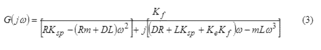
- m is the mass [kg]
- x (t) is the amount of displacement of the magnet assembly 114 (vibrator) [m]
- K f is thrust constant one resonance system [N / A]
- i ( t) is The current [A] flowing through the coil 112
- Ksp is the spring constant [N / m] of the spring 113
- D is the damping coefficient [N / (m / s)] of one resonance system.
- e (t) is a voltage [V] applied to the coil 112
- R is a resistance [ ⁇ ] of the coil 112
- L is an inductance [H] of the coil 112
- K e is a counter electromotive force of one resonance system. Constant [V / (m / s)].
- the transfer function G (j ⁇ ) of the vibration unit 11 is derived as in the following equation (3), and shows a specific response to the electric signal supplied from the drive circuit 12.
- the characteristic of vibration (output of one resonance system) of the vibration unit 11 varies depending on the type of electric signal (input to one resonance system) supplied from the drive circuit 12 to the vibration unit 11.
- an impulse signal, a swept signal, and a random signal are used for the vibration unit 11 attached to the inspection object 100 using a structure made of ABS (Acrylonitrile Butadiene Styrene) resin as the inspection object 100.
- ABS Acrylonitrile Butadiene Styrene
- an impulse signal, swept signal, and even when a random signal was fed to the vibrating unit 11, in the vicinity of 5kHz is the resonant frequency f r of the inspection object 100, the amplitude of the vibration of the inspection target 100 It turns out that is the maximum.
- an impulse signal, even when the supplied swept signals, and any random signal to the vibration unit 11, capable of detecting the resonant frequency f r of the vibration of the inspection target 100 is there.
- the case of supplying the impulse signal to the vibration unit 11, the amplitude at the resonant frequency f r of the most significant test object 100 is maximized.
- the results show an optimum that to be supplied to the impulse signal to the vibration unit 11 to detect accurately the resonant frequency f r of the test object 100.
- FIG. 6 a case made of plastic is used as the inspection object 100, and an impulse signal, a swept signal, and a random signal are supplied to the vibration unit 11 to the vibration unit 11 attached to the inspection object 100.
- An example of the vibration of the inspection object 100 when the vibration unit 11 is vibrated is shown.
- the mass and spring constant of the inspection object 100 in the example of FIG. 6 are different from the mass and spring constant of the inspection object 100 in the example of FIG.
- the resonance frequency f r of the inspection object 100 in the example of FIG. 6 is a near 0.125KHz.
- the case of supplying the impulse signal to the vibration unit 11 the amplitude is the largest at a frequency band other than the vicinity of 0.125kHz is the resonant frequency f r of the test object 100.
- the amplitude in the vicinity of 0.125kHz is the resonant frequency f r of the inspection object 100 is the largest.
- the case of supplying the impulse signal to the vibration unit 11 it is impossible to accurately detect the resonant frequency f r of the vibration of the test object 100.
- the type of electric signal to be supplied from the drive circuit 12 to the vibration unit 11 differs depending on the mass of the test object 100 and the spring constant.
- the drive circuit 12 is configured to supply any one of an impulse signal, a swept signal, and a random signal to the vibration unit 11, the sensing device 10 is configured to resonate vibrations of various inspection objects 100. it is possible to detect the frequency f r.
- vibration unit 11 attached to the inspection object 100 vibrates, vibration is applied to the inspection object 100.
- vibration is applied from the vibration unit 11 to the inspection object 100, vibration of the inspection object 100 is excited.
- the inspection target 100 is oscillated at the resonant frequency f r which is determined by the following formula (4), the inspection object 100 is vibrated largely.
- m 1 is the mass of the inspection object 100
- m 2 is the mass of the vibration unit 11 attached to the inspection object 100
- K sp is the spring constant of the inspection object 100.
- the resonance frequency fr of the inspection object 100 depends on the mass m 1 of the inspection object 100 and the spring constant Ksp , so that the state of the inspection object 100 depends on factors such as the passage of time and failure. , i.e., if the mass m 1 and the spring constant K sp changes, also changes the resonance frequency f r of the test object 100.
- the mass of the inspection target 100 by factors of time and failure or the like is an example of change in the resonance frequency f r of the inspection object 100 when the increased m 1b from m 1a is shown.
- the resonance frequency fr is a low frequency. Shift to the side.
- the resonance frequency f r of the inspection object 100 is shifted to the high frequency side.
- the mass m 1 of the inspection object 100 decreases due to factors such as the passage of time or failure
- a case where the inspection object 100 is a metal member made of a metal material such as iron can be given.
- the mass m 1 of the inspection object 100 decreases.
- the mass m 1 of the inspection target 100 increases due to factors such as the passage of time or failure
- a case where the inspection target 100 is installed outdoors can be given.
- dust, dust, earth and sand, water, or the like accumulates on the inspection object 100 over time, the mass m 1 of the inspection object 100 increases.
- the spring constant Ksp of the inspection target 100 changes due to factors such as the passage of time or a failure
- the inspection target 100 is a component configured by connecting a plurality of parts.
- the spring constant K sp of the inspection object 100 is changed.
- the inspection object 100 is a wheel of a tire of a vehicle, by loosening of the wheel, the spring constant K sp of the inspection object 100 is changed.
- the spring constant Ksp of the inspection object 100 also changes when the inspection object 100 is a structure made of concrete and cracks or cracks occur in the inspection object 100 due to factors such as the passage of time or impact.
- the detection system 1 has the above-described corrosion and weathering of the inspection object 100, an increase in accumulation of the inspection object 100, loosening of bolts and screws of the inspection object 100, bending of the beam, loosening of the wheel, and inspection. Various phenomena such as cracks and cracks in the object 100 can be detected.
- the drive circuit 12 has a function of supplying an electric signal for driving (vibrating) the vibration unit 11 to the vibration unit 11.
- the drive circuit 12 is configured to supply at least one of an impulse signal, a swept signal, and a random signal to the vibration unit 11 in accordance with control data received from the detection processing device 20 via the communication unit 14. Yes.
- the sensor 13 has a function of detecting the vibration of the inspection object 100 generated by the vibration applied from the vibration unit 11. Vibration information regarding the vibration of the inspection object 100 detected by the sensor 13 is transmitted to the detection processing device 20 via the communication unit 14.
- the vibration information transmitted from the sensor 13 to the detection processing device 20 is, for example, acceleration of vibration (motion) of the inspection target 100 or the like.
- processing such as Fourier transform on the vibration information, the amplitude (energy) for each frequency of vibration of the inspection object 100 can be acquired.
- the sensor 13 is not particularly limited as long as the vibration of the inspection object 100 can be detected.
- the sensor 13 is attached to the inspection object 100 and is provided apart from the inspection object 100 and an acceleration sensor that detects acceleration of movement of the inspection object 100.
- a laser sensor or the like that irradiates the inspection object 100 with a laser and detects the movement of the inspection object 100 based on the laser reflected from the inspection object 100 can be used as the sensor 13.
- the communication unit 14 communicates with the detection processing device 20, receives control data from the detection processing device 20, and further transmits a vibration information related to the vibration of the inspection target 100 detected by the sensor 13 to the detection processing device 20. Have.
- the communication unit 14 communicates with the detection processing device 20 by wired communication.
- the detection processing device 20 and the detection processing device 20 are connected to each other using a wireless communication technology such as NFC (Near Field Radio Communication), Wi-Fi, or Bluetooth (registered trademark). Communicate.
- the power supply to each component of the sensing device 10 may be realized by a built-in power source such as a battery built in the sensing device 10 or may be provided outside the sensing device 10 and may be provided by the power supply line. It may be realized by an external power source connected to.
- the detection processing device 20 transmits control data to the sensing device 10, and further receives vibration information regarding the vibration of the inspection target 100 detected by the sensor 13 from the sensing device 10, and performs an inspection based on the received vibration information. It has a function of detecting the state change of the object 100.
- the detection processing device 20 may be implemented as a single device, or an arbitrary arithmetic device such as a desktop computer, a laptop computer, a notebook computer, a workstation, a tablet computer, a mobile phone, a smartphone, a PDA, or a wearable terminal. It may be implemented in the inside.
- the detection processing device 20 includes at least one processor 21 that performs control of the detection processing device 20, a memory 22 that stores data, programs, modules, and the like necessary for controlling the detection processing device 20, and reception.
- the resonant frequency calculation unit 23 for calculating the vibration of the reference resonant frequency f ref and / or resonant frequency calculator 23 of the inspection object 100 is calculated resonant frequency f r of the vibration of the inspection target 100 a storage unit 24 for storing the resonance frequency f r, a coherence calculator 25 for calculating a coherence gamma 2 between the vibration of the inspection object 100 of the vibration unit 11 of the sensing device 10, the resonance frequency calculator 23 of the vibration of the test object 100 calculated the resonance frequency f r and the reference resonance frequency f in the storage unit 24 by comparing the previous resonance frequency f r of the vibration of the test object 100 that is stored in the ref or the storage unit 24, the state change detecting section 26 for detecting a state change of the inspection object 100, the sensing
- the processor 21 exchanges various data and various instructions with each component via the data bus 28 and controls the detection processing device 20.
- the processor 21 can provide a desired function by using each component of the detection processing device 20.
- the processor 21, by using a resonant frequency calculation unit 23, based on the received vibration information, it is possible to calculate the resonant frequency f r of the vibration of the inspection object 100, by using the coherence calculation unit 25,
- the coherence ⁇ 2 between the vibration of the vibration unit 11 of the sensing device 10 and the vibration of the inspection object 100 can be calculated, and the state change of the inspection object 100 can be detected by using the state change detection unit 26. it can.
- the processor 21 transmits control data to the sensing device 10 via the communication unit 27 at predetermined intervals (for example, every hour, every day, every week, every month, etc.), and the vibration of the inspection object 100 is transmitted to the sensing device 10.
- the control data transmitted from the processor 21 is used for specifying whether the drive circuit 12 of the sensing device 10 supplies an impulse signal, a swept signal, or a random signal to the vibration unit 11.
- the drive circuit 12 that has received the control data supplies an impulse signal, a swept signal, or a random signal to the vibration unit 11 according to the control data, and drives the vibration unit 11.
- the processor 21 includes one or more microprocessors, a microcomputer, a microcontroller, a digital signal processor (DSP), a central processing unit (CPU), a memory control unit (MCU), an image processing processing unit (GPU), a state An arithmetic unit that performs arithmetic processing such as signal manipulation based on computer-readable instructions such as a machine, a logic circuit, an application specific integrated circuit (ASIC), or a combination thereof.
- the processor 21 is configured to fetch computer readable instructions (eg, data, programs, modules, etc.) stored in the memory 22 and perform signal manipulation and control.
- the memory 22 includes a volatile storage medium (for example, RAM, SRAM, DRAM), a nonvolatile storage medium (for example, ROM, EPROM, EEPROM, flash memory, hard disk, optical disk, CD-ROM, digital versatile disk (DVD), A removable or non-removable computer readable medium comprising a magnetic cassette, magnetic tape, magnetic disk), or a combination thereof.
- a volatile storage medium for example, RAM, SRAM, DRAM
- a nonvolatile storage medium for example, ROM, EPROM, EEPROM, flash memory, hard disk, optical disk, CD-ROM, digital versatile disk (DVD), A removable or non-removable computer readable medium comprising a magnetic cassette, magnetic tape, magnetic disk), or a combination thereof.
- the resonance frequency calculation unit 23 based on the vibration information received from the sensing device 10 via the communication unit 27 has a function of calculating a resonant frequency f r of the vibration of the test object 100. Specifically, the resonance frequency calculation unit 23 performs processing such as Fourier transform on the received vibration information, and the amplitude (energy) for each frequency of vibration of the inspection object 100 as shown in FIG. Is calculated. The resonance frequency calculation unit 23 identifies the frequency having the highest amplitude (energy) as a resonance frequency f r of the vibration of the test object 100.
- Storage unit 24 may be any non-volatile recording medium for storing the resonance frequency f r the vibration of the reference resonant frequency f ref and / or resonant frequency calculator 23 of the inspection object 100 is calculated (e.g., hard disk, flash memory) It is. Referring the resonance frequency f ref of the vibration of the test object 100 is a resonant frequency f r of the vibration of the inspection target 100 when the test object 100 is in the normal state, is measured before operation of the detection system 1, the storage unit 24 Saved in.
- the resonance frequency f r of the vibration of the test object 100 in which the resonance frequency calculator 23 calculates is stored in the storage unit 24 .
- Such accumulated data can be used to track the state change of the inspection object 100 in time series, and can provide useful information for maintenance inspection of the inspection object 100. Further, such accumulated data may be transmitted as a report to an administrator of the inspection object 100 at predetermined intervals (for example, every hour, every day, every week, every month, etc.).
- the storage unit 24 further stores vibration information related to the vibration of the vibration unit 11 acquired in advance.
- the vibration information related to the vibration of the vibration unit 11 includes at least vibration information related to the vibration of the vibration unit 11 when the drive circuit 12 supplies the impulse signal to the vibration unit 11 and vibration information related to the vibration of the vibration unit 11 when the swept signal is supplied. And vibration information related to vibration of the vibration unit 11 when a random signal is supplied.
- Such vibration information relating to the vibration of the vibration unit 11 is used for calculating the coherence ⁇ 2 between the vibration of the vibration unit 11 of the sensing device 10 and the vibration of the inspection object 100 by the coherence calculation unit 25 described later. .
- the coherence calculation unit 25 is based on the vibration information regarding the vibration of the vibration unit 11 of the sensing device 10 stored in the storage unit 24 and the vibration information regarding the vibration of the inspection target 100 received from the sensing device 10.
- the coherence ⁇ 2 between the vibration of the vibration unit 11 and the vibration of the inspection object 100 is calculated.
- the coherence calculation unit 25 calculates a coherence value between the vibration of the vibration unit 11 of the sensing device 10 and the vibration of the inspection target 100 by the following equation (5).
- W xx is the power spectrum of the input vibration, that is, the power spectrum of the vibration unit 11, and is calculated from the vibration information related to the vibration of the vibration unit 11 of the sensing device 10 stored in the storage unit 24.
- W yy is the power spectrum of the output vibration, that is, the power spectrum of the vibration of the inspection object 100.
- W xy is a cross spectrum of the vibration of the vibration unit 11 and the vibration of the inspection object 100.
- the coherence ⁇ 2 as described above represents the strength of the relationship between the input vibration and the output vibration.
- the processor 21 changes the control data according to the value of the coherence ⁇ 2 calculated by the coherence calculation unit 25. For example, when the impulse signal is supplied from the drive circuit 12 to the vibration unit 11, if the coherence ⁇ 2 is less than 0.5, the processor 21 may supply the vibration unit 11 with the vibration unit 11 even if the impulse signal is supplied. It is determined that 11 resonances were not excited. Thereafter, the processor 21 changes the control data so as to supply the swept signal or the random signal from the drive circuit 12 to the vibration unit 11, and transmits the changed control data to the drive circuit 12 via the communication unit 27.
- State change detection unit 26 the resonance frequency calculation unit 23 and the resonance frequency f r of the vibration of the test object 100 calculated, see the resonance in the storage unit 24 frequency f ref or inspection is stored in the storage unit 24 the target 100 It has a function of detecting a change in the state of the inspection object 100 by comparing the resonance frequency f r before the vibration. Difference Specifically, the state change detecting section 26, the resonance frequency f r of the resonance frequency calculation unit 23 calculates a reference resonance frequency f ref or previous resonance frequency f r is stored in the storage unit 24 calculating the absolute value of the calculated difference, i.e., the variation of the resonance frequency f r is determined whether more than a predetermined threshold value. The predetermined threshold is appropriately determined depending on factors such as the size, the constituent material, and the shape of the inspection target 100.
- the state change detection unit 26 detects a state change of the test object 100.
- the state change detecting section 26 detects that there is no change in the state of the inspection object 100 To do. Thereafter, the processor 21 executes processing according to the detection result of the state change detection unit 26.
- the processor 21 is a user device such as an administrator of the inspection target 100 (desktop computer, laptop computer, laptop computer, workstation, tablet computer, mobile phone, smartphone). , A PDA, a wearable terminal, etc.) to send a message indicating that a change in the state of the inspection object 100 has been detected.
- the administrator of the inspection object 100 can know the state change of the inspection object 100 and can take an appropriate action.
- the communication unit 27 communicates with the sensing device 10, transmits control data to the sensing device 10, and further receives vibration information from the sensing device 10 regarding the vibration of the inspection target 100 detected by the sensor 13 of the sensing device 10. It has a function. Further, the communication unit 27 has a function of communicating with the user device of the administrator of the inspection target 100.
- the administrator of the inspection object 100 communicates with the detection processing device 20 via the communication unit 27, and executes detection processing at various settings (for example, every interval (daily, weekly, etc.) of the detection processing device 20. Can be changed. Further, the detection processing device 20 can transmit the above-described accumulated data and message to the user device of the administrator of the inspection target 100 via the communication unit 27.
- the communication unit 27 performs communication with the sensing device 10 and the user device of the administrator of the inspection target 100 using various wired communication and wireless communication. Further, the communication unit 27 may communicate with various external devices other than the sensing device 10 and the user device of the administrator of the inspection target 100 using various wired communication and wireless communication.
- the power supply to each component of the detection processing device 20 may be realized by a built-in power source such as a battery built in the detection processing device 20, or provided outside the detection processing device 20 and by a power supply line. It may be realized by an external power source connected to the detection processing device 20.
- the detection system 1 of the present invention applies the coil 112 through which the electric signal supplied from the drive circuit 12 flows, the spring 113 provided so as to vibrate, and the spring 113 to apply vibration to the inspection target 100.
- a VCM type vibration unit 11 having a magnet 114b that is attached and spaced apart from the coil 112 is used. Therefore, unlike the prior art using an impulse hammer, the vibration unit 11 does not need to be made of a material resistant to impact. Furthermore, since the VCM type vibration unit 11 can generate a large vibration with a relatively low input voltage, it is not necessary to apply a high input voltage to the vibration unit 11 as in the prior art using a piezoelectric element. . Therefore, according to the present invention, simplification, downsizing, and power saving of the detection system 1 can be realized.
- the sensing device 10 and the detection processing device 20 are described as separate devices housed in separate cases, but the present invention is not limited to this.
- a unit that provides a function corresponding to the sensing device 10 and a unit that provides a function corresponding to the detection processing device 20 may be housed in one case and implemented as one device.
- FIG. 8 is a conceptual diagram showing a detection system according to the second embodiment of the present invention.
- the detection system of the second embodiment will be described with a focus on differences from the detection system of the first embodiment, and description of similar matters will be omitted.
- the detection system 1 includes a plurality of sensing devices 10, and the detection processing device 20 is connected to the plurality of sensing devices 10 via a network 30 so that they can communicate with each other. Except for this, it is the same as the detection system 1 of the first embodiment.
- the detection processing device 20 in the present embodiment may be a single device connected to the network 30 or may be implemented in a server connected to the network 30.
- a plurality of sensing devices 10 of the present embodiment are attached to one inspection object 100.
- the plurality of sensing devices 10 are communicably connected to the detection processing device 20 via the network 30.
- the network 30 is an extensive network such as an intranet, a local area network (LAN), a wide area network (WAN), the Internet, or a combination thereof.
- the network 30 may be a dedicated network or a shared network.
- the shared network is a connection between various types of networks, and communicates with each other using various protocols (for example, HTTP, TCP / IP, WAP).
- the network 30 may include various network devices including routers, bridges, servers, computing devices, storage devices, and the like.
- the detection processing device 20 receives vibration information of the vibration of the inspection object 100 from the plurality of sensing devices 10 via the network 30. As a result, the detection processing device 20 can detect not only the presence / absence of individual state changes at the location of the inspection object 100 to which each sensing device 10 is attached, but also the presence / absence of the state change of the entire inspection object 100. be able to.
- the detection system 1 having such a configuration is particularly useful when the inspection target 100 is a huge structure such as a bridge or a tunnel.
- FIG. 9 is a conceptual diagram showing a detection system according to the third embodiment of the present invention.
- the detection system according to the third embodiment will be described with a focus on differences from the detection system according to the second embodiment, and description of similar matters will be omitted.
- the detection system 1 of the third embodiment is the same as the detection system 1 of the second embodiment, except that a plurality of sensing devices 10 are attached to a plurality of different inspection objects 100, respectively.
- a plurality of sensing devices 10 are attached to a plurality of different inspection objects 100, respectively. Such an aspect is particularly useful when a plurality of relatively small inspection objects 100 are spaced apart from each other.
- FIG. 10 is a flowchart showing the detection method of the present invention.
- step S ⁇ b> 101 control data is generated by the processor 21 of the detection processing device 20, and the generated control data is transmitted to the sensing device 10 via the communication unit 27.
- the control data generated and transmitted is used in the sensing device 10 to specify whether the drive circuit 12 supplies an impulse signal, a swept signal, or a random signal to the vibration unit 11.
- step S ⁇ b> 102 control data is received by the communication unit 14 of the sensing device 10 and sent to the drive circuit 12.
- the drive circuit 12 supplies an impulse signal, a swept signal, or a random signal to the vibration unit 11 according to the control data.
- step S103 the vibration unit 11 is driven by the electrical signal supplied from the drive circuit 12, and the vibration unit 11 vibrates. When the vibration unit 11 vibrates, the vibration of the vibration unit 11 is applied to the inspection object 100 and the inspection object 100 vibrates.
- step S104 the sensor 13 detects the vibration of the inspection object 100.
- step S ⁇ b> 105 the sensor 13 transmits vibration information relating to the detected vibration of the inspection object 100 to the detection processing device 20 via the communication unit 14.
- step S ⁇ b> 106 the detection processing device 20 receives vibration information regarding the vibration of the inspection target 100 via the communication unit 27.
- step S ⁇ b> 107 the processor 21 of the detection processing device 20 calculates a coherence ⁇ 2 between the vibration of the vibration unit 11 of the sensing device 10 and the vibration of the inspection target 100 using the coherence calculation unit 25.
- the coherence ⁇ 2 is calculated based on the vibration information related to the vibration of the vibration unit 11 stored in the storage unit 24 and the received vibration information related to the vibration of the inspection target 100.
- the vibration information relating to the vibration of the vibration unit 11 used at this time corresponds to the vibration when an electric signal of a type specified by the control data is supplied to the vibration unit 11.
- the calculated coherence gamma 2 it is determined whether or not 0.5 or more.
- the processor 21 determines that the vibration (resonance) of the inspection target 100 is not sufficiently excited by the vibration of the vibration unit 11, and the processing is performed.
- the process proceeds to step S108.
- the processor 21, the number of coherence gamma 2 is less than 0.5, whether or not reached a predetermined number of times is determined.
- the predetermined number of times corresponds to the number of electrical signals that the drive circuit 12 can supply to the vibration unit 11. For example, when the drive circuit 12 is configured to be able to supply three types of impulse signals, swept signals, and random signals, the predetermined number of times is three.
- step S108 the number of times the coherence gamma 2 is less than 0.5, if it is determined that does not reach the predetermined number, the process proceeds to step S109.
- step S ⁇ b> 109 the processor 21 changes the control data and changes the electrical signal supplied from the drive circuit 12 to the vibration unit 11 to a type that has not been supplied to the vibration unit 11. For example, when an impulse signal has already been supplied to the vibration unit 11, the electric signal supplied from the drive circuit 12 to the vibration unit 11 is changed to a swept signal or a random signal. Thereafter, the process returns to S101.
- step S108 the number of times the coherence gamma 2 is less than 0.5, if it is determined to have reached the predetermined number, the process proceeds to step S110.
- the fact that the number of times that the coherence ⁇ 2 was less than 0.5 has reached a predetermined number indicates that the vibration of the vibration unit 11 caused by the electric signal that can be supplied to the vibration unit 11 by the drive circuit 12 is the vibration ( Resonance) cannot be excited sufficiently. In this case, there is a high possibility that some trouble has occurred in the sensing device 10. For example, it is assumed that there is a possibility that the vibration unit 11 has been removed from the inspection target 100, the vibration unit 11 or the sensor 13 has failed, or the sensing device 10 has not been supplied with sufficient power.
- step S110 the processor 21 transmits an error message indicating that an error has been detected to a user device such as an administrator of the inspection target 100 via the communication unit 27, and the process ends.
- a user device such as an administrator of the inspection target 100
- the administrator of the inspection target 100 can take appropriate measures such as checking the sensing device 10.
- step S107 when the calculated coherence gamma 2 is determined to be 0.5 or more, the processing proceeds to step S111.
- the processor 21 uses the resonant frequency calculation unit 23, based on the vibration information about the vibration of the test object 100, to calculate the resonance frequency f r of the vibration of the test object 100.
- the resonance frequency f r of the vibration of the test object 100 calculated are stored in the storage unit 24 as the resonance frequency f r of the oscillation of the current inspection target 100.
- step S112 the processor 21 uses the state change detecting section 26, the resonance frequency f r of the vibration of the test object 100 in which the resonance frequency calculation unit 23 calculates the reference resonant frequency f ref or the storage unit in the storage unit 24 by comparing the previous resonance frequency f r of the vibration of the test object 100 that is stored in 24, and the resonance frequency f r of the resonance frequency calculation unit 23 calculates, references which are stored in the storage unit 24 the difference between the resonance frequency f ref or previous resonance frequency f r is calculated.
- step S113 the absolute value of the difference between the resonant frequency f r of the resonance frequency calculation unit 23 calculates a reference resonance frequency f ref or previous resonance frequency f r is stored in the storage unit 24, i.e., the resonant frequency variation of f r is equal to or more than a predetermined threshold value is determined.
- step S113 if the absolute value of the calculated difference (variation of the resonance frequency f r) is determined to be below a predetermined threshold, the process proceeds to step S114.
- step S114 it is detected that there is no change in the state of the inspection object 100, the processor 21 executes a process according to the detection result, and the process ends.
- step S113 if the absolute value of the calculated difference (variation of the resonance frequency f r) is determined to be equal to or greater than the predetermined threshold value, the process proceeds to step S115.
- step S115 it is detected that the state of the inspection object 100 has changed, and the processor 21 executes a process according to the detection result, and the process ends.
- the present invention is not limited to this.
- Each component of the present invention can be replaced with any component that can exhibit the same function, or any component of the present invention can be added to each component of the present invention.
- each component of the detection system 1 may be realized by hardware, may be realized by software, or may be realized by a combination thereof.
- the detection system 1 of the present invention may include a plurality of detection processing devices 20.
- Each of the plurality of detection processing devices 20 may detect a state change of the inspection target 100 by communicating with the same sensing device 10 or detect a state change of the inspection target 100 by communicating with a different sensing device 10. May be.
- the number and types of steps of the detection method S100 shown in FIG. 10 are merely illustrative examples, and the present invention is not necessarily limited thereto. It is within the scope of the present invention that any step can be added or combined for any purpose or any step can be deleted without departing from the principle and intention of the present invention.
- the detection system and the detection method of the present invention are, as a vibrator for vibrating an object to be inspected, a coil through which an electric signal supplied from a drive circuit flows, a spring provided so as to be able to vibrate, and a coil attached to the spring.
- a VCM (Voice Coil Motor) type vibration unit including a magnet disposed apart from each other. Therefore, unlike the prior art using an impulse hammer, the vibration unit (vibrator) does not need to be made of a material resistant to impact. Furthermore, since the VCM type vibration unit can generate a large vibration with a relatively low input voltage, it is not necessary to apply a high input voltage to the vibration unit as in the prior art using a piezoelectric element. Therefore, according to the present invention, simplification, downsizing, and power saving of the detection system can be realized. Therefore, the present invention has industrial applicability.
Landscapes
- Physics & Mathematics (AREA)
- General Physics & Mathematics (AREA)
- Chemical & Material Sciences (AREA)
- Health & Medical Sciences (AREA)
- Life Sciences & Earth Sciences (AREA)
- Engineering & Computer Science (AREA)
- Biochemistry (AREA)
- Analytical Chemistry (AREA)
- General Health & Medical Sciences (AREA)
- Immunology (AREA)
- Pathology (AREA)
- Aviation & Aerospace Engineering (AREA)
- Acoustics & Sound (AREA)
- Electromagnetism (AREA)
- Signal Processing (AREA)
- Ceramic Engineering (AREA)
- Mechanical Engineering (AREA)
- Food Science & Technology (AREA)
- Optics & Photonics (AREA)
- Medicinal Chemistry (AREA)
- Measurement Of Mechanical Vibrations Or Ultrasonic Waves (AREA)
- Investigating Or Analyzing Materials By The Use Of Ultrasonic Waves (AREA)
Abstract
Description
(1)検査対象の状態変化を検出するための検出システムであって、
前記検査対象に取り付けられ、前記検査対象に振動を加えるための振動ユニットと、前記振動ユニットを駆動させるための電気信号を前記振動ユニットに供給するための駆動回路と、前記振動ユニットから加えられた前記振動によって発生した前記検査対象の振動を検出するためのセンサーと、を備えるセンシングデバイスと、
前記センシングデバイスから、前記センサーが検出した前記検査対象の前記振動に関する振動情報を受信し、前記振動情報に基づいて前記検査対象の前記状態変化を検出するための検出処理デバイスと、を含み、
前記センシングデバイスの前記振動ユニットは、前記駆動回路から供給された前記電気信号が流れるコイルと、振動可能に設けられたバネと、前記バネに取り付けられ、前記コイルと離間して配置されたマグネットと、を備えることを特徴とする検出システム。
前記検出処理デバイスは、算出された前記検査対象の前記振動の前記共振周波数と、前記記憶部内に事前に保存されている前記検査対象の前記振動の前記共振周波数とを比較することにより、前記共振周波数の前記変化量を算出し、前記共振周波数の前記変化量が所定のしきい値以上である場合に、前記検査対象の前記状態変化を検出する上記(2)に記載の検出システム。
前記検出処理デバイスは、前記複数のセンシングデバイスのそれぞれから前記検査対象の前記振動に関する前記振動情報を受信する上記(1)ないし(5)のいずれかに記載の検出システム。
駆動回路から前記検査対象に取り付けられた振動ユニットに電気信号を供給し、前記振動ユニットを駆動させることにより、前記検査対象に振動を加える工程と、
センサーを用いて、前記振動ユニットから加えられた前記振動によって発生した前記検査対象の振動を検出する工程と、
プロセッサーを用いて、前記センサーが検出した前記検査対象の前記振動に基づいて、前記検査対象の前記状態変化を検出する工程と、を含み、
前記振動ユニットは、前記駆動回路から供給された前記電気信号が流れるコイルと、振動可能に設けられたバネと、前記バネに取り付けられ、前記コイルと離間して配置されたマグネットと、を備えることを特徴とする検出方法。
図1は、本発明の第1実施形態に係る検出システムを示す概念図である。図2は、図1に示す振動ユニットの斜視図である。図3は、図1に示す振動ユニットの分解斜視図である。図4は、図1に示す振動ユニットの断面図である。図5は、図1に示す振動ユニットにインパルス信号、スウェプト信号、およびランダム信号のいずれかを供給した場合に発生する検査対象の振動の例を示す図である。図6は、図1に示す振動ユニットにインパルス信号、スウェプト信号、およびランダム信号のいずれかを供給した場合に発生する検査対象の振動の別の例を示す図である。図7は、図1に示す検査対象の質量の変化によって発生する検査対象の振動の特性の変化を説明するための図である。


次に、図8を参照して、本発明の第2実施形態に係る検出システムを説明する。図8は、本発明の第2実施形態に係る検出システムを示す概念図である。以下、第2実施形態の検出システムについて、第1実施形態の検出システムとの相違点を中心に説明し、同様の事項については、その説明を省略する。
次に、図9を参照して、本発明の第3実施形態に係る検出システムを説明する。図9は、本発明の第3実施形態に係る検出システムを示す概念図である。以下、第3実施形態の検出システムについて、第2実施形態の検出システムとの相違点を中心に説明し、同様の事項については、その説明を省略する。
次に、図10を参照して、本発明の検出方法を説明する。なお、本発明の検出方法は、上述した本発明の検出システム1および本発明の検出システム1と同等の機能を有する任意のシステムを用いて実行することができるが、以下、検出システム1を用いて実行されるものとして説明する。図10は、本発明の検出方法を示すフローチャートである。
Claims (7)
- 検査対象の状態変化を検出するための検出システムであって、
前記検査対象に取り付けられ、前記検査対象に振動を加えるための振動ユニットと、前記振動ユニットを駆動させるための電気信号を前記振動ユニットに供給するための駆動回路と、前記振動ユニットから加えられた前記振動によって発生した前記検査対象の振動を検出するためのセンサーと、を備えるセンシングデバイスと、
前記センシングデバイスから、前記センサーが検出した前記検査対象の前記振動に関する振動情報を受信し、前記振動情報に基づいて前記検査対象の前記状態変化を検出するための検出処理デバイスと、を含み、
前記センシングデバイスの前記振動ユニットは、前記駆動回路から供給された前記電気信号が流れるコイルと、振動可能に設けられたバネと、前記バネに取り付けられ、前記コイルと離間して配置されたマグネットと、を備えることを特徴とする検出システム。 - 前記検出処理デバイスは、前記振動情報から前記検査対象の前記振動の共振周波数を算出し、前記共振周波数の変化量に基づいて、前記検査対象の前記状態変化を検出する請求項1に記載の検出システム。
- 前記検出処理デバイスは、前記検査対象の前記振動の前記共振周波数を記憶するための記憶部を含み、
前記検出処理デバイスは、算出された前記検査対象の前記振動の前記共振周波数と、前記記憶部内に事前に保存されている前記検査対象の前記振動の前記共振周波数とを比較することにより、前記共振周波数の前記変化量を算出し、前記共振周波数の前記変化量が所定のしきい値以上である場合に、前記検査対象の前記状態変化を検出する請求項2に記載の検出システム。 - 前記駆動回路は、前記電気信号として、インパルス信号、スウェプト信号、およびランダム信号のいずれかを前記振動ユニットに供給するよう構成されている請求項1ないし3のいずれかに記載の検出システム。
- 前記センサーは、前記検査対象に取り付けられた加速度センサーまたは前記検査対象から離間して配置されたレーザーセンサーである請求項1ないし4のいずれかに記載の検出システム。
- 前記検出システムは、複数の前記センシングデバイスを含み、
前記検出処理デバイスは、前記複数のセンシングデバイスのそれぞれから前記検査対象の前記振動に関する前記振動情報を受信する請求項1ないし5のいずれかに記載の検出システム。 - 検査対象の状態変化を検出するための検出方法であって、
駆動回路から前記検査対象に取り付けられた振動ユニットに電気信号を供給し、前記振動ユニットを駆動させることにより、前記検査対象に振動を加える工程と、
センサーを用いて、前記振動ユニットから加えられた前記振動によって発生した前記検査対象の振動を検出する工程と、
プロセッサーを用いて、前記センサーが検出した前記検査対象の前記振動に基づいて、前記検査対象の前記状態変化を検出する工程と、を含み、
前記振動ユニットは、前記駆動回路から供給された前記電気信号が流れるコイルと、振動可能に設けられたバネと、前記バネに取り付けられ、前記コイルと離間して配置されたマグネットと、を備えることを特徴とする検出方法。
Priority Applications (5)
| Application Number | Priority Date | Filing Date | Title |
|---|---|---|---|
| JP2019515177A JP7177355B2 (ja) | 2017-04-28 | 2018-03-29 | 検出システムおよび検出方法 |
| US16/609,195 US11249052B2 (en) | 2017-04-28 | 2018-03-29 | Detection system and detection method |
| EP18791366.0A EP3617699B1 (en) | 2017-04-28 | 2018-03-29 | Detection system and detection method |
| CN201880028182.XA CN110573874B (zh) | 2017-04-28 | 2018-03-29 | 检测系统和检测方法 |
| US17/646,643 US12247951B2 (en) | 2017-04-28 | 2021-12-30 | Detection system and detection method |
Applications Claiming Priority (2)
| Application Number | Priority Date | Filing Date | Title |
|---|---|---|---|
| JP2017-090620 | 2017-04-28 | ||
| JP2017090620 | 2017-04-28 |
Related Child Applications (2)
| Application Number | Title | Priority Date | Filing Date |
|---|---|---|---|
| US16/609,195 A-371-Of-International US11249052B2 (en) | 2017-04-28 | 2018-03-29 | Detection system and detection method |
| US17/646,643 Continuation US12247951B2 (en) | 2017-04-28 | 2021-12-30 | Detection system and detection method |
Publications (1)
| Publication Number | Publication Date |
|---|---|
| WO2018198665A1 true WO2018198665A1 (ja) | 2018-11-01 |
Family
ID=63919115
Family Applications (1)
| Application Number | Title | Priority Date | Filing Date |
|---|---|---|---|
| PCT/JP2018/013498 Ceased WO2018198665A1 (ja) | 2017-04-28 | 2018-03-29 | 検出システムおよび検出方法 |
Country Status (5)
| Country | Link |
|---|---|
| US (2) | US11249052B2 (ja) |
| EP (1) | EP3617699B1 (ja) |
| JP (1) | JP7177355B2 (ja) |
| CN (1) | CN110573874B (ja) |
| WO (1) | WO2018198665A1 (ja) |
Cited By (2)
| Publication number | Priority date | Publication date | Assignee | Title |
|---|---|---|---|---|
| CN110631790A (zh) * | 2019-09-25 | 2019-12-31 | 歌尔科技有限公司 | 一种穿戴类设备及其检测方法 |
| US12501009B2 (en) | 2023-03-27 | 2025-12-16 | Seiko Epson Corporation | Projector device, projector, supporting device, abnormality determination device, and abnormality determination method |
Families Citing this family (4)
| Publication number | Priority date | Publication date | Assignee | Title |
|---|---|---|---|---|
| JP7152100B2 (ja) * | 2018-03-16 | 2022-10-12 | ミツミ電機株式会社 | センシングシステム、センシング方法、および非一時的コンピューター可読媒体 |
| US10703625B1 (en) * | 2019-03-29 | 2020-07-07 | Industrial Technology Research Institute | Microelectromechanical system (MEMS) apparatus with adjustable spring |
| CN112665710A (zh) * | 2020-12-21 | 2021-04-16 | 陕西宝光集团有限公司 | 设备运行状态的检测方法、装置、电子设备及存储介质 |
| CN113640301B (zh) * | 2021-08-03 | 2024-02-09 | 江苏省特种设备安全监督检验研究院 | 特种设备的螺栓检测方法 |
Citations (11)
| Publication number | Priority date | Publication date | Assignee | Title |
|---|---|---|---|---|
| JPH0471533A (ja) * | 1990-07-10 | 1992-03-06 | Shiseido Co Ltd | 生体表面部の力学特性の測定方法と装置並びにそのためのセンサ内蔵形加振器の構造 |
| JPH08152394A (ja) * | 1994-11-29 | 1996-06-11 | Ohbayashi Corp | コンクリート硬化度判定装置および方法 |
| US5533381A (en) * | 1994-06-10 | 1996-07-09 | Seale; Joseph B. | Conversion of liquid volume, density, and viscosity to frequency signals |
| JP2000314730A (ja) * | 1999-05-06 | 2000-11-14 | Non-Destructive Inspection Co Ltd | 材料の振動疲労管理方法 |
| JP2001056319A (ja) * | 1999-08-20 | 2001-02-27 | Matsushita Electric Ind Co Ltd | 青果物選果方法及び青果物選果装置 |
| JP2004085412A (ja) * | 2002-08-28 | 2004-03-18 | Koden Electronics Co Ltd | 固体内部の振動検査装置 |
| JP2008157945A (ja) | 2006-12-22 | 2008-07-10 | General Electric Co <Ge> | 原子炉のジェットポンプセンシングラインの周波数測定 |
| JP2009186423A (ja) * | 2008-02-08 | 2009-08-20 | Ntn Corp | 検査方法および検査ユニット |
| JP2015111091A (ja) | 2013-11-06 | 2015-06-18 | パナソニック株式会社 | センサ装置、異常検知システム |
| US20150253266A1 (en) * | 2012-10-19 | 2015-09-10 | Resodyn Corporation | Methods and systems for detecting flaws in an object |
| JP2016053548A (ja) * | 2014-09-04 | 2016-04-14 | 鈴木 基行 | 非破壊検査装置 |
Family Cites Families (26)
| Publication number | Priority date | Publication date | Assignee | Title |
|---|---|---|---|---|
| DE1130631B (de) | 1960-01-22 | 1962-05-30 | Schenck Gmbh Carl | Schwingsystem mit stufenlos veraenderlicher Frequenz und Amplitude, insbesondere fuer Ruetteltische, dynamische Werkstoffpruefmaschinen u. dgl. |
| GB8309030D0 (en) | 1983-03-31 | 1983-05-11 | Cawley P | Testing of structures by impact |
| WO1989007249A1 (fr) | 1986-08-28 | 1989-08-10 | Mitsui Engineering & Shipbuilding Co., Ltd. | Procede du type a impact et appareil d'inspection de structures |
| JPH01219555A (ja) * | 1988-02-26 | 1989-09-01 | Mitsubishi Petrochem Co Ltd | 衝撃試験器 |
| US5003824A (en) * | 1989-12-26 | 1991-04-02 | Matsushita Electric Industrial Co., Ltd. | Vibration/acceleration sensor |
| US5847817A (en) * | 1997-01-14 | 1998-12-08 | Mcdonnell Douglas Corporation | Method for extending range and sensitivity of a fiber optic micro-doppler ladar system and apparatus therefor |
| US6488117B1 (en) * | 2001-08-24 | 2002-12-03 | Thomas E. Owen | Vertical-force vibrator seismic wave source |
| NO339298B1 (no) * | 2003-10-10 | 2016-11-21 | Optoplan As | Aktiv koherensreduksjon for interferometeravspørring |
| JP2007198996A (ja) * | 2006-01-30 | 2007-08-09 | Toray Eng Co Ltd | 共振検査装置及び共振検査方法 |
| IL184868A0 (en) * | 2007-07-26 | 2008-03-20 | Univ Bar Ilan | Motion detection system and method |
| GB2446685B (en) * | 2007-11-27 | 2009-04-01 | Perpetuum Ltd | An electromechanical generator for converting mechanical vibrational energy into electrical energy |
| JP5272441B2 (ja) * | 2008-02-20 | 2013-08-28 | ミツミ電機株式会社 | 振動発生装置 |
| US8214178B2 (en) * | 2008-06-04 | 2012-07-03 | Vibration Technologies, Llc | Method and system for optimizing the vibrational characteristics of a structure |
| JP2010104864A (ja) * | 2008-10-28 | 2010-05-13 | Sanyo Electric Co Ltd | 往復振動発生器 |
| JP2011169446A (ja) * | 2010-02-22 | 2011-09-01 | Mitsumi Electric Co Ltd | 板バネおよびレンズ駆動装置 |
| US8645101B2 (en) * | 2011-02-10 | 2014-02-04 | Siemens Energy, Inc. | Method for monitoring the condition of a vibration sensor |
| EP2721402B1 (en) * | 2011-06-20 | 2019-09-18 | Vibrant Corporation | Part evaluation method using both resonance and surface vibration data |
| JP5874505B2 (ja) * | 2012-04-10 | 2016-03-02 | オムロン株式会社 | 振動エネルギー検出装置、振動エネルギー検出システム |
| JP6036143B2 (ja) * | 2012-10-11 | 2016-11-30 | ミツミ電機株式会社 | 発電装置 |
| FR2997495B1 (fr) * | 2012-10-30 | 2015-07-24 | Eurocopter France | Procede de surveillance de capteurs vibratoires |
| US9097604B2 (en) * | 2012-11-30 | 2015-08-04 | The Boeing Company | Electrodynamic modal test impactor system and method |
| EP2921842B1 (de) | 2014-03-18 | 2020-06-24 | Russenberger Prüfmaschinen AG | Resonanzprüfmaschine |
| US10024756B2 (en) * | 2014-10-28 | 2018-07-17 | Embraer S.A. | Method and system for structural health monitoring with frequency synchronization |
| WO2016117160A1 (ja) * | 2015-01-20 | 2016-07-28 | オリンパス株式会社 | 走査型内視鏡装置 |
| US20190011402A1 (en) * | 2016-02-22 | 2019-01-10 | Nec Corporation | Inspection device, inspection method, and non-transitory recoding medium storing inspection program |
| US10660523B2 (en) * | 2017-07-07 | 2020-05-26 | Hideo Ando | Light-source unit, measurement apparatus, near-infrared microscopic apparatus, optical detection method, imaging method, calculation method, functional bio-related substance, state management method, and manufacturing method |
-
2018
- 2018-03-29 CN CN201880028182.XA patent/CN110573874B/zh active Active
- 2018-03-29 US US16/609,195 patent/US11249052B2/en active Active
- 2018-03-29 EP EP18791366.0A patent/EP3617699B1/en active Active
- 2018-03-29 JP JP2019515177A patent/JP7177355B2/ja active Active
- 2018-03-29 WO PCT/JP2018/013498 patent/WO2018198665A1/ja not_active Ceased
-
2021
- 2021-12-30 US US17/646,643 patent/US12247951B2/en active Active
Patent Citations (11)
| Publication number | Priority date | Publication date | Assignee | Title |
|---|---|---|---|---|
| JPH0471533A (ja) * | 1990-07-10 | 1992-03-06 | Shiseido Co Ltd | 生体表面部の力学特性の測定方法と装置並びにそのためのセンサ内蔵形加振器の構造 |
| US5533381A (en) * | 1994-06-10 | 1996-07-09 | Seale; Joseph B. | Conversion of liquid volume, density, and viscosity to frequency signals |
| JPH08152394A (ja) * | 1994-11-29 | 1996-06-11 | Ohbayashi Corp | コンクリート硬化度判定装置および方法 |
| JP2000314730A (ja) * | 1999-05-06 | 2000-11-14 | Non-Destructive Inspection Co Ltd | 材料の振動疲労管理方法 |
| JP2001056319A (ja) * | 1999-08-20 | 2001-02-27 | Matsushita Electric Ind Co Ltd | 青果物選果方法及び青果物選果装置 |
| JP2004085412A (ja) * | 2002-08-28 | 2004-03-18 | Koden Electronics Co Ltd | 固体内部の振動検査装置 |
| JP2008157945A (ja) | 2006-12-22 | 2008-07-10 | General Electric Co <Ge> | 原子炉のジェットポンプセンシングラインの周波数測定 |
| JP2009186423A (ja) * | 2008-02-08 | 2009-08-20 | Ntn Corp | 検査方法および検査ユニット |
| US20150253266A1 (en) * | 2012-10-19 | 2015-09-10 | Resodyn Corporation | Methods and systems for detecting flaws in an object |
| JP2015111091A (ja) | 2013-11-06 | 2015-06-18 | パナソニック株式会社 | センサ装置、異常検知システム |
| JP2016053548A (ja) * | 2014-09-04 | 2016-04-14 | 鈴木 基行 | 非破壊検査装置 |
Non-Patent Citations (1)
| Title |
|---|
| See also references of EP3617699A4 |
Cited By (3)
| Publication number | Priority date | Publication date | Assignee | Title |
|---|---|---|---|---|
| CN110631790A (zh) * | 2019-09-25 | 2019-12-31 | 歌尔科技有限公司 | 一种穿戴类设备及其检测方法 |
| CN110631790B (zh) * | 2019-09-25 | 2022-01-25 | 歌尔科技有限公司 | 一种穿戴类设备及其检测方法 |
| US12501009B2 (en) | 2023-03-27 | 2025-12-16 | Seiko Epson Corporation | Projector device, projector, supporting device, abnormality determination device, and abnormality determination method |
Also Published As
| Publication number | Publication date |
|---|---|
| CN110573874A (zh) | 2019-12-13 |
| US20200057029A1 (en) | 2020-02-20 |
| EP3617699A1 (en) | 2020-03-04 |
| EP3617699A4 (en) | 2021-01-06 |
| JP7177355B2 (ja) | 2022-11-24 |
| EP3617699B1 (en) | 2024-10-23 |
| CN110573874B (zh) | 2023-03-14 |
| JPWO2018198665A1 (ja) | 2020-03-12 |
| US20220120716A1 (en) | 2022-04-21 |
| US12247951B2 (en) | 2025-03-11 |
| US11249052B2 (en) | 2022-02-15 |
Similar Documents
| Publication | Publication Date | Title |
|---|---|---|
| WO2018198665A1 (ja) | 検出システムおよび検出方法 | |
| JP5888486B2 (ja) | 発電装置、発電装置の制御方法、電子機器、および移動手段 | |
| EP3737924B1 (en) | Integration of proximity sensors with magnetostrictive torque sensors | |
| US20110048133A1 (en) | Vibration element coupled with non-linear force to improve non-resonant frequency response | |
| GB2539529A (en) | System, apparatus, and method for resonator and coriolis axis control in vibratory gyroscopes | |
| US8610331B2 (en) | Driving method for piezoelectric vibrator, and dust removing device and ultrasonic motor using the driving method | |
| JP7101088B2 (ja) | 地盤締固めのためのデバイスおよびそれを操作しモニタするための方法 | |
| CN104364623B (zh) | 驻极体型振动检测系统、外部振动信息的生成方法、关于外部振动的传递函数信息的生成方法、外部振动信息的生成程序以及关于外部振动的传递函数信息的生成程序 | |
| CN109387796B (zh) | 用于磁致伸缩式扭矩传感器的改进的间隙补偿 | |
| JP2005277471A (ja) | スピーカ | |
| US10488199B2 (en) | Gyroscope with piezoelectric monocrystal transducers | |
| CN222505652U (zh) | 用于振弦传感器的振动桥以及振弦传感器 | |
| JP6232961B2 (ja) | 変位量検出装置、および変位量検出方法 | |
| US7415879B2 (en) | Angular velocity sensor and angular velocity detector | |
| JP5285861B2 (ja) | 荷重変換用音叉振動装置 | |
| KR101821953B1 (ko) | 관성형 가진기 | |
| JP7488865B2 (ja) | ボルトの緩み推定装置、ボルトの緩み推定方法及びボルトの緩み推定プログラム | |
| KR20170019754A (ko) | 피에조 액추에이터 구동 방법 및 장치 | |
| WO2016035707A1 (ja) | 圧電振動装置の駆動装置及び駆動方法 | |
| JP6183160B2 (ja) | 振動発電装置 | |
| JP6463173B2 (ja) | 加速度取得装置、タイヤ、及びタイヤの製造方法 | |
| JP2006250643A (ja) | 角速度センサの異常検出装置 | |
| JPH099652A (ja) | 超音波モータの駆動装置 | |
| JP2008026062A (ja) | エンジンブロックの振動伝達特性解析装置 | |
| JP2007178386A (ja) | 複合センサ |
Legal Events
| Date | Code | Title | Description |
|---|---|---|---|
| 121 | Ep: the epo has been informed by wipo that ep was designated in this application |
Ref document number: 18791366 Country of ref document: EP Kind code of ref document: A1 |
|
| ENP | Entry into the national phase |
Ref document number: 2019515177 Country of ref document: JP Kind code of ref document: A |
|
| NENP | Non-entry into the national phase |
Ref country code: DE |
|
| WWE | Wipo information: entry into national phase |
Ref document number: 2018791366 Country of ref document: EP |
|
| ENP | Entry into the national phase |
Ref document number: 2018791366 Country of ref document: EP Effective date: 20191128 |