WO2018199286A1 - 路面プロファイル推定装置、路面プロファイル推定システム、路面プロファイル推定方法及び路面プロファイル推定プログラム - Google Patents
路面プロファイル推定装置、路面プロファイル推定システム、路面プロファイル推定方法及び路面プロファイル推定プログラム Download PDFInfo
- Publication number
- WO2018199286A1 WO2018199286A1 PCT/JP2018/017182 JP2018017182W WO2018199286A1 WO 2018199286 A1 WO2018199286 A1 WO 2018199286A1 JP 2018017182 W JP2018017182 W JP 2018017182W WO 2018199286 A1 WO2018199286 A1 WO 2018199286A1
- Authority
- WO
- WIPO (PCT)
- Prior art keywords
- road surface
- displacement
- angular velocity
- acceleration
- vehicle
- Prior art date
- Legal status (The legal status is an assumption and is not a legal conclusion. Google has not performed a legal analysis and makes no representation as to the accuracy of the status listed.)
- Ceased
Links
Images


Classifications
-
- E—FIXED CONSTRUCTIONS
- E01—CONSTRUCTION OF ROADS, RAILWAYS, OR BRIDGES
- E01C—CONSTRUCTION OF, OR SURFACES FOR, ROADS, SPORTS GROUNDS, OR THE LIKE; MACHINES OR AUXILIARY TOOLS FOR CONSTRUCTION OR REPAIR
- E01C23/00—Auxiliary devices or arrangements for constructing, repairing, reconditioning, or taking-up road or like surfaces
- E01C23/01—Devices or auxiliary means for setting-out or checking the configuration of new surfacing, e.g. templates, screed or reference line supports; Applications of apparatus for measuring, indicating, or recording the surface configuration of existing surfacing, e.g. profilographs
-
- G—PHYSICS
- G01—MEASURING; TESTING
- G01C—MEASURING DISTANCES, LEVELS OR BEARINGS; SURVEYING; NAVIGATION; GYROSCOPIC INSTRUMENTS; PHOTOGRAMMETRY OR VIDEOGRAMMETRY
- G01C7/00—Tracing profiles
- G01C7/02—Tracing profiles of land surfaces
- G01C7/04—Tracing profiles of land surfaces involving a vehicle which moves along the profile to be traced
-
- B—PERFORMING OPERATIONS; TRANSPORTING
- B60—VEHICLES IN GENERAL
- B60W—CONJOINT CONTROL OF VEHICLE SUB-UNITS OF DIFFERENT TYPE OR DIFFERENT FUNCTION; CONTROL SYSTEMS SPECIALLY ADAPTED FOR HYBRID VEHICLES; ROAD VEHICLE DRIVE CONTROL SYSTEMS FOR PURPOSES NOT RELATED TO THE CONTROL OF A PARTICULAR SUB-UNIT
- B60W40/00—Estimation or calculation of non-directly measurable driving parameters for road vehicle drive control systems not related to the control of a particular sub unit, e.g. by using mathematical models
- B60W40/02—Estimation or calculation of non-directly measurable driving parameters for road vehicle drive control systems not related to the control of a particular sub unit, e.g. by using mathematical models related to ambient conditions
- B60W40/06—Road conditions
-
- G—PHYSICS
- G01—MEASURING; TESTING
- G01B—MEASURING LENGTH, THICKNESS OR SIMILAR LINEAR DIMENSIONS; MEASURING ANGLES; MEASURING AREAS; MEASURING IRREGULARITIES OF SURFACES OR CONTOURS
- G01B21/00—Measuring arrangements or details thereof, where the measuring technique is not covered by the other groups of this subclass, unspecified or not relevant
- G01B21/30—Measuring arrangements or details thereof, where the measuring technique is not covered by the other groups of this subclass, unspecified or not relevant for measuring roughness or irregularity of surfaces
Definitions
- the present invention relates to a road surface profile estimation device, a road surface profile estimation system, a road surface profile estimation method, and a road surface profile estimation program. About.
- a road surface profile In order to evaluate a longitudinal profile of a road surface (hereinafter referred to as a road surface profile), unevenness of the road surface is measured, and an index such as an IRI (International Roughness Index) may be calculated. Information on the road surface profile may be used to determine whether or not the road surface needs to be repaired or to evaluate the comfort when the vehicle travels.
- IRI International Roughness Index
- Japanese Patent Application Laid-Open No. 2017-040486 discloses a bicycle travel distance and vertical displacement based on data measured by a speed sensor, an acceleration sensor, and an angular speed sensor attached to the bicycle, and a vertical direction based on the travel distance and acceleration. There is described a measuring apparatus for obtaining a road surface profile of a bicycle road by associating displacements with each other or associating a vertical displacement based on acceleration and a vertical displacement based on angular velocity with a travel distance.
- the road profile may be estimated by a dedicated vehicle equipped with a high-precision laser rangefinder.
- a dedicated vehicle for estimating the road surface profile is expensive, and operators that can be used are limited.
- a dedicated vehicle for estimating a road surface profile may be designed on the assumption that a road surface profile of an expressway is estimated, and may not always be suitable for estimating a road surface profile of a general road.
- the present invention provides a road surface profile estimation device, a road surface profile estimation system, a road surface profile estimation method, and a road surface profile estimation program capable of accurately estimating a profile of an arbitrary road surface including a general road using a general-purpose vehicle. provide.
- a road surface profile estimation device includes an acquisition unit that acquires acceleration in the vertical direction and an angular velocity related to a pitch axis with respect to a road surface on which a vehicle contacts, and calculates vertical displacement by integrating the acceleration, A first calculation unit that integrates angular velocity to calculate an angular displacement related to the pitch axis, and a variable that represents the unevenness of the road surface on which the vehicle travels, a variable that represents the vertical movement of the vehicle, and a rotation that relates to the pitch axis of the vehicle based on the simulation model A prediction unit that predicts temporal development of a state variable including a variable representing motion, and a second calculation unit that calculates acceleration, angular velocity, displacement, and angular displacement from the state variable predicted by the prediction unit based on the observation model; , Acceleration and angular velocity acquired by the acquisition unit, displacement and angular displacement calculated by the first calculation unit, acceleration and angular velocity calculated by the second calculation unit Comprises the data assimilation
- not only the acceleration in the vertical direction and the angular velocity with respect to the pitch axis but also the vertical displacement and the angular displacement with respect to the pitch axis are used for data assimilation with respect to the road surface on which the vehicle is in contact with the road surface.
- the profile of an arbitrary road surface including a general road can be accurately estimated using a general-purpose vehicle.
- the smoothing unit for smoothing the state variable further based on the acceleration and angular velocity acquired by the acquiring unit after the time predicted by the predicting unit and the displacement and angular displacement calculated by the first calculating unit You may prepare.
- the profile of the road surface is estimated with higher accuracy by using not only the vertical acceleration of the vehicle and the angular velocity related to the pitch axis but also the vertical displacement and the angular displacement related to the pitch axis for data smoothing. be able to.
- the simulation model is a vehicle half car model
- the state variable may be a variable representing the state of the half car model.
- variable representing the unevenness of the road surface includes the vertical displacement and speed of the front tire of the half car model and the vertical displacement and speed of the rear tire of the half car model, and represents the vertical motion of the vehicle. Includes the vertical displacement and speed of the center of gravity of the half car model, the vertical displacement and speed of the front suspension of the half car model, and the vertical displacement and speed of the rear suspension of the half car model.
- Variables representing rotational motion with respect to the pitch axis may include rotational angles and angular velocities with respect to the pitch axis passing through the center of gravity of the half car model.
- the simulation model is a model representing the time evolution of the state variable by linear transformation or nonlinear transformation of the state variable and Gaussian noise or non-Gaussian noise
- the observation model is the linear transformation or nonlinear transformation of the state variable or Gaussian noise.
- it may be a model that calculates acceleration, angular velocity, displacement, and angular displacement by non-Gaussian noise.
- the time evolution of the state variable is represented by a simulation model including nonlinear transformation and non-Gaussian noise
- the observation is represented by an observation model including nonlinear transformation and non-Gaussian noise.
- the simulation model is a model representing the time evolution of the state variable by linear transformation of the state variable and Gaussian noise
- the observation model is acceleration, angular velocity, displacement and angular displacement by the linear transformation of the state variable and Gaussian noise.
- the update unit may update the state variable so as to minimize the square error of the state variable.
- the time evolution of the state variable is represented by a simulation model including linear transformation and Gaussian noise
- the observation is represented by an observation model including linear transformation and Gaussian noise. Can be estimated.
- a road surface profile estimation system includes an accelerometer that is installed in a vehicle and that measures acceleration in a direction perpendicular to a road surface on which the vehicle contacts, and an angular velocity that is installed in the vehicle and that is related to the pitch axis of the vehicle.
- a first calculation unit that integrates acceleration to calculate vertical displacement, integrates angular velocity to calculate angular displacement with respect to the pitch axis, and a variable that represents unevenness of a road surface on which the vehicle travels based on a simulation model;
- not only the acceleration in the vertical direction and the angular velocity with respect to the pitch axis but also the vertical displacement and the angular displacement with respect to the pitch axis are used for data assimilation with respect to the road surface on which the vehicle is in contact with the road surface.
- the profile of an arbitrary road surface including a general road can be accurately estimated using a general-purpose vehicle.
- a road surface profile estimation apparatus method includes a first step of acquiring an acceleration in a vertical direction and an angular velocity related to a pitch axis with respect to a road surface on which a vehicle contacts, and integrating the acceleration in a vertical direction.
- a sixth step of estimating is
- not only the acceleration in the vertical direction and the angular velocity with respect to the pitch axis but also the vertical displacement and the angular displacement with respect to the pitch axis are used for data assimilation with respect to the road surface on which the vehicle is in contact with the road surface.
- the profile of an arbitrary road surface including a general road can be accurately estimated using a general-purpose vehicle.
- a road surface profile estimation apparatus program provides a computer provided in a road surface profile estimation apparatus, an acquisition unit that acquires acceleration in a direction perpendicular to a road surface on which a vehicle contacts and an angular velocity related to a pitch axis, acceleration To calculate the vertical displacement, to calculate the angular displacement with respect to the pitch axis by integrating the angular velocity, based on the simulation model, the variable representing the unevenness of the road surface on which the vehicle travels, the upper and lower of the vehicle
- a prediction unit that predicts temporal development of a state variable including a variable that represents motion and a variable that represents rotational motion with respect to the pitch axis of the vehicle, and based on the observation model, from the state variable predicted by the prediction unit, acceleration, angular velocity, displacement, and A second calculation unit that calculates angular displacement, an acceleration and an angular velocity acquired by the acquisition unit, and a variable calculated by the first calculation unit.
- an update unit for updating the state variable by data assimilation of the angular displacement and the acceleration, angular velocity, displacement and angular displacement calculated by the second calculation unit, and a variable representing the road surface unevenness included in the state variable And function as an estimation unit for estimating a road surface profile.
- not only the acceleration in the vertical direction and the angular velocity with respect to the pitch axis but also the vertical displacement and the angular displacement with respect to the pitch axis are used for data assimilation with respect to the road surface on which the vehicle is in contact with the road surface.
- the profile of an arbitrary road surface including a general road can be accurately estimated using a general-purpose vehicle.
- a road surface profile estimation device capable of accurately estimating a profile of an arbitrary road surface including a general road using a general-purpose vehicle. Can be provided.
- 1 is a schematic diagram of a road surface profile estimation system according to a first embodiment of the present invention.
- 1 is a functional block diagram of a road surface profile estimation apparatus according to a first embodiment of the present invention. It is a conceptual diagram of the simulation model used with the road surface profile estimation apparatus which concerns on 1st Embodiment of this invention. It is a flowchart of the 1st process performed by the road surface profile estimation apparatus which concerns on 1st Embodiment of this invention. It is a flowchart of the 2nd process performed by the road surface profile estimation apparatus which concerns on 1st Embodiment of this invention.
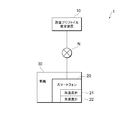
- FIG. 1 is a schematic diagram of a road surface profile estimation system 1 according to the first embodiment of the present invention.
- the road surface profile estimation system 1 includes a vehicle 30, an accelerometer 21 that measures acceleration in a direction perpendicular to the road surface on which the vehicle 30 contacts, an angular velocity meter 22 that measures an angular velocity related to the pitch axis of the vehicle 30, and the vehicle 30 And a road surface profile estimation device 10 that estimates a profile of a traveling road surface.
- the accelerometer 21 and the angular velocity meter 22 are built in the smartphone 20.
- the smartphone 20 may be installed in an arbitrary place such as a dashboard or a trunk room of the vehicle 30.
- the accelerometer 21 and the angular velocity meter 22 may be installed in the vehicle 30 independently.
- the accelerometer 21 measures the acceleration in the vertical direction with respect to the road surface on which the vehicle 30 contacts the ground, but does not necessarily measure only the acceleration in the vertical direction, and also measures the acceleration in the horizontal direction with respect to the road surface. It may be.
- the accelerometer 21 only needs to measure at least a component in the direction perpendicular to the road surface among the plurality of components of the acceleration of the vehicle 30.
- the angular velocity meter 22 measures the angular velocity related to the pitch axis of the vehicle 30, but does not necessarily measure only the angular velocity related to the pitch axis, and measures the angular velocity related to the roll axis of the vehicle 30 and the angular velocity related to the yaw axis. It may be.
- the angular velocity meter 22 only needs to measure at least the angular velocity related to the pitch axis among the angular velocities related to the plurality of axes of the vehicle 30.
- the road surface profile estimation device 10 estimates the profile of the road surface on which the vehicle 30 travels based on acceleration, angular velocity, and the like measured by the accelerometer 21 and the angular velocity meter 22.
- the road surface profile estimation apparatus 10 is connected to the smartphone 20 via the communication network N.
- the communication network N may be a wired or wireless communication network.
- the road surface profile estimation apparatus 10 does not necessarily need to be an apparatus independent of the smartphone 20 and may be configured integrally with the smartphone 20. In that case, the smartphone 20 may function as the road surface profile estimation device 10 by executing the road surface estimation program installed in the smartphone 20.
- the vehicle 30 may be an automobile that travels on a road surface with four tires. However, the vehicle 30 may be a three-wheel or two-wheel vehicle, or may be five or more wheels. An arbitrary size automobile may be used as the vehicle 30. In this specification, a case where a light vehicle (Light), a small vehicle (Small), and a medium vehicle (Middle) are used as the vehicle 30 will be described.
- Light Light
- Small Small
- Middle medium vehicle
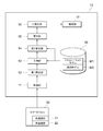
- FIG. 2 is a functional block diagram of the road surface profile estimation apparatus 10 according to the first embodiment of the present invention.
- the road surface profile estimation apparatus 10 includes an acquisition unit 11, a first calculation unit 12, a prediction unit 13, a second calculation unit 14, an update unit 15, a smoothing unit 16, an estimation unit 17, and a storage unit 18.
- the acquisition unit 11 acquires the acceleration in the direction perpendicular to the road surface on which the vehicle 30 contacts and the angular velocity related to the pitch axis.
- the acquisition unit 11 may communicate with the smartphone 20, acquire acceleration from the accelerometer 21 built in the smartphone 20, and acquire angular velocity from the angular velocity meter 22.
- the first calculation unit 12 integrates the acceleration to calculate the vertical displacement, and integrates the angular velocity to calculate the angular displacement related to the pitch axis.
- the first calculation unit 12 calculates the displacement in the vertical direction by second-order integrating the acceleration acquired by the acquisition unit 11 with respect to time.
- the 1st calculation part 12 calculates the angular displacement regarding a pitch axis by carrying out the first-order integration of the angular velocity acquired by the acquisition part 11 regarding time.
- the prediction unit 13 is a state variable time including a variable that represents the unevenness of the road surface on which the vehicle 30 travels, a variable that represents the vertical motion of the vehicle 30, and a variable that represents rotational motion related to the pitch axis of the vehicle 30.
- the simulation model M1 is stored in the storage unit 18.
- the simulation model M1 is a half car model of the vehicle 30, and the state variable is a variable representing the state of the half car model. More specifically, the variables representing road surface unevenness include vertical displacement and speed of the front tire of the half car model and vertical displacement and speed of the rear tire of the half car model.
- the variables representing the vertical motion of the vehicle 30 are the vertical displacement and speed of the center of gravity of the half car model, the vertical displacement and speed of the front suspension of the half car model, and the vertical direction of the rear suspension of the half car model. Displacement and speed. Further, the variable representing the rotational motion related to the pitch axis of the vehicle 30 includes a rotation angle and an angular velocity related to the pitch axis passing through the center of gravity of the half car model.
- the second calculation unit 14 determines, based on the state variable predicted by the prediction unit 13, the acceleration in the vertical direction with respect to the road surface on which the vehicle 30 contacts, the angular velocity with respect to the pitch axis, the vertical displacement, and the pitch. Calculate the angular displacement about the axis.
- the observation model M2 is stored in the storage unit 18.
- the updating unit 15 includes the acceleration and angular velocity acquired by the acquiring unit 11, the displacement and angular displacement calculated by the first calculating unit 12, and the acceleration, angular velocity, displacement and angular displacement calculated by the second calculating unit 14.
- Update state variables by data assimilation refers to a process of updating the state variable predicted by the simulation model M1 based on the actual measurement value to increase the prediction accuracy. A specific example of data assimilation will be described in detail later.
- the smoothing unit 16 smoothes the state variable based on the acceleration and angular velocity acquired by the acquiring unit 11 after the time point predicted by the predicting unit 13 and the displacement and angular displacement calculated by the first calculating unit 12. To do.
- the estimation unit 17 estimates a road surface profile based on a variable representing road surface unevenness included in the state variable.
- the road surface profile refers to the longitudinal profile of the road surface.
- the storage unit 18 stores a simulation model M1 and an observation model M2.
- the simulation model M1 is a model representing the time evolution of the state variable by linear transformation of the state variable and Gaussian noise
- the observation model M2 is the linear transformation of the state variable and Gaussian noise.
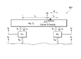
- FIG. 3 is a conceptual diagram of a simulation model M1 used by the road surface profile estimation apparatus 10 according to the first embodiment of the present invention.
- the simulation model M1 is a half car model and includes 12 state variables and 13 parameters.
- the state variables are the vertical displacement h f and speed dh f / dt of the front tire of the half car model, the vertical displacement h r and speed and dh r / dt of the rear tire of the half car model, and the half car model Vertical displacement u b and speed du b / dt of the center of gravity, vertical displacement u f and speed du f / dt of the front suspension of the half car model, and vertical displacement u r of the rear suspension of the half car model And a speed du r / dt and a rotation angle ⁇ and an angular speed d ⁇ / dt with respect to the pitch axis passing through the center of gravity of the half car model.
- the spring coefficient k tf of the front tire half car model the mass m f of the front tires, the spring constant of the front suspension k f and damping coefficient c f, and the spring constant k tr rear tire of half car model, and the mass m r of the rear tires, the spring coefficient k r and the damping coefficient c r of the rear suspension, the moment of inertia I y around the vehicle body mass m b and the pitch axis of the half-car model, the front tire from the center of gravity of the half-car model
- the horizontal distance L f to the ground contact point, the horizontal distance L r from the center of gravity of the half car model to the ground contact point of the rear tire, and the horizontal distance d from the ground contact point of the front tire to the installation point of the accelerometer 21 and the angular velocity meter 22 including.
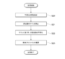
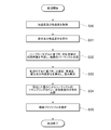
- FIG. 4 is a flowchart of the first process executed by the road surface profile estimation apparatus 10 according to the first embodiment of the present invention.
- the first process is a process in which the road surface profile estimation device 10 performs data assimilation of a state variable and a measured value by a Kalman filter.
- the road surface profile estimation device 10 acquires the acceleration in the vertical direction and the angular velocity related to the pitch axis with respect to the road surface on which the vehicle 30 contacts with the acquisition unit 11 (S10).
- the acceleration measurement by the accelerometer 21 and the angular velocity measurement by the angular velocity meter 22 may be performed at predetermined time intervals.
- the acquisition unit 11 may acquire the acceleration and the angular velocity every time measurement is performed by the accelerometer 21 and the angular velocity meter 22, or may acquire the acceleration and the angular velocity collectively after the measurement is completed.
- the first calculation unit 12 integrates the acceleration acquired by the acquisition unit 11 to calculate the vertical displacement, and integrates the angular velocity to calculate the angular displacement related to the pitch axis (S11).
- the acceleration and angular velocity acquired by the acquisition unit 11 and the displacement and angular displacement calculated by the first calculation unit 12 are collectively expressed as a vector y.
- the prediction unit 13 predicts the time evolution of the state variable based on the half car model (S12).
- the time evolution of the state variable is obtained based on the equation of motion represented by the following equation (1).
- the vector U is expressed by the following mathematical formula (2).
- the vector U is the vertical displacement u b of the center of gravity of the half car model, the angular displacement ⁇ with respect to the pitch axis passing through the center of gravity, the vertical displacement u f of the front suspension of the half car model, and the vertical direction of the rear suspension of the half car model.
- the displacement u r including as a component of the vector.
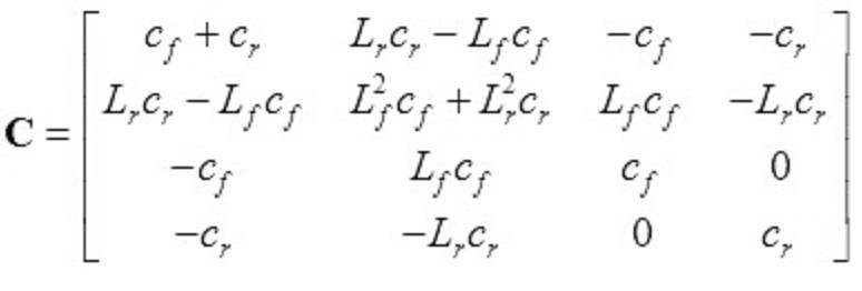
- the matrices M, C, and K are given by the following mathematical formulas (3) to (5), and are quantities depending on parameters.
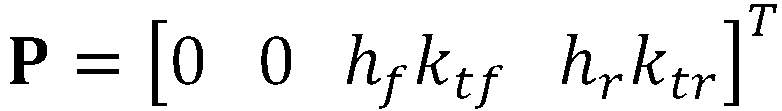
- Equation (1) is given by a vector P that depends on a variable representing the road surface irregularities.
- the vector P is given by the following formula (6).
- the twelve state variables are represented by a vector x a as shown in Equation (7).
- the prediction unit 13 represents an error that may be caused by modeling the behavior of the vehicle 30 using a half car model by a noise term.
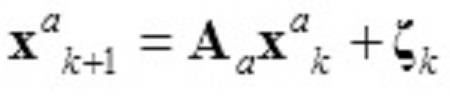
- the prediction unit 13 obtains the time evolution of the state variable x a by the following formula (8).
- Equation (1) the time evolution of the state variable represented by Equation (1) as a linear transformation in unit time steps.
- a a exp (A ⁇ t) is expressed, A is expressed by the following mathematical formula (9).
- ⁇ t represents a unit time step.
- the matrices M, C, and K are shown in Equations (3) to (5).
- I 4 ⁇ 4 is a 4 ⁇ 4 unit matrix
- the matrices O 4 ⁇ 4 , O 4 ⁇ 2 , and O 2 ⁇ 2 are 4 ⁇ 4, 4 ⁇ 2, and 2 ⁇ 2 zero matrices, respectively.
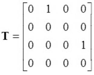
- the matrix Z is an amount represented by the following formula (10)
- the matrix T is an amount represented by the following formula (11).
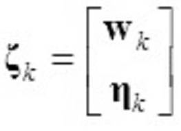
- ⁇ k on the right side of Equation (8) is a noise term at time step k.
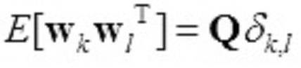
- the noise term ⁇ k includes an eight-dimensional vector w k and a four-dimensional vector ⁇ k as represented by the following formula (12).
- the average is 0,
- the variance-covariance matrix is Gaussian noise with Q. Note that ⁇ k, l is the Kronecker delta.
- noise term eta k for an average of 0, variance-covariance matrix is Gaussian noise of S.
- Equation (8) representing the time evolution of the state variable, the vertical displacement h f and speed dh f / dt of the front tire of the half car model and the vertical displacement of the rear tire of the half car model
- Equation (8) representing the time evolution of the state variable
- the time evolution of the four-dimensional vector u that summarizes h r, velocity, and dh r / dt is given by the following equation (15).
- the second calculator 14 calculates acceleration, angular velocity, displacement, and angular displacement from the state variables predicted by the predictor 13 based on the observation model M2 (S13).
- the second calculation unit 14 is a vector y that summarizes acceleration, angular velocity, displacement, and angular displacement from the state variable x a predicted by the prediction unit 13 based on the observation model M2 represented by the following mathematical formula (16). Is calculated.
- the second calculator 14 models the observation by the linear transformation C a of the state variable, and models the observation error by the noise term v k .
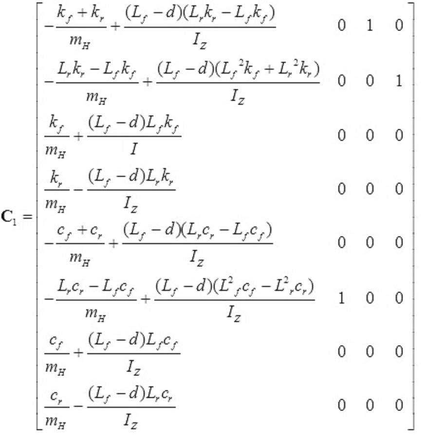
- the matrix C1 is given by the following formula (18).
- the noise term v k on the right side of Equation (14) is Gaussian noise with an average of 0 and a variance-covariance matrix of R.
- the update unit 15 updates the state variable with the optimum Kalman gain (S14).
- the optimum Kalman gain is an update coefficient determined so as to minimize the square error of the state variable, and is given by the following equation (20).
- Equation (20) is the variance of the state variables before being updated at time step k + 1.
- the initial value of the expected value of the state variable is given by the following formula (21), and the initial value of the variance is given by the following formula (22). Note that the state variable x a with a hat symbol represents an estimated value.
- the updating unit 15 obtains the expected value of the updated state variable x a by the following formula (25).
- y k + 1 on the right side is the acceleration and angular velocity acquired by the acquiring unit 11 and the degree of displacement and angular displacement calculated by the first calculating unit 12 at the time step k + 1. Is the value measured.
- the second term on the right side corrects the state variable by the value obtained by multiplying the difference between the measured value y k + 1 and the observed value calculated from the state variable x k + 1 a ⁇ by the optimum Kalman gain G k + 1. It is a term to do.
- the update unit 15 obtains the variance of the updated state variable x a by the following formula (26).
- the state variable can be estimated with high accuracy by predicting the state variable at each time step and updating it according to the difference from the measured value.
- the simulation model M1 including linear transformation and Gaussian noise
- the observation by the observation model M2 including linear transformation and Gaussian noise
- FIG. 5 is a flowchart of the second process executed by the road surface profile estimation apparatus 10 according to the first embodiment of the present invention.
- the second process is a process in which the road surface profile estimation apparatus 10 performs a state variable smoothing process to estimate a road surface profile.
- the smoothing part 16 receives designation
- the smoothing unit 16 smoothes all the state variables x k + 1 , x k after that for smoothing the state variable x k of the time step k. +2 ,... X T may be used.
- the smoothing unit 16 initializes the expected value of the state variable after smoothing by the following formula (27), and initializes the variance of the state variable after smoothing by the following formula (28).
- the smoothing unit 16 calculates the back propagation gain ⁇ in the smoothing process by the following mathematical formula (29) (S21).
- the estimation unit 17 estimates a road surface profile based on a variable representing road surface unevenness included in the state variable (S23). Specifically, the estimation unit 17, the vertical displacement h f of the front tires of the half car model, based on the displacement h r vertical rear tire half car model to estimate the profile of the road surface.
- the road surface profile estimation apparatus 10 not only the acceleration in the vertical direction and the angular velocity with respect to the pitch axis but also the vertical displacement and the angular displacement with respect to the pitch axis are assimilated to the road surface on which the vehicle 30 contacts. By using it, a highly stable analysis can be realized, and a profile of an arbitrary road surface including a general road can be accurately estimated using a general-purpose vehicle. Further, not only the acceleration in the vertical direction and the angular velocity with respect to the pitch axis but also the displacement in the vertical direction and the angular displacement with respect to the pitch axis are used for data smoothing, whereby the road surface profile can be estimated with higher accuracy.
- FIG. 6 is a first graph showing the relationship between the travel distance and the road surface profile estimated by the road surface profile estimation system 1 according to the first embodiment of the present invention.
- the horizontal axis indicates the travel distance (Distance) in units of meters (m)
- the vertical axis indicates the road surface profile in units of meters (m).
- a road surface profile estimated by the road surface profile estimation system 1 according to the present embodiment using a light vehicle (Light) is indicated by a solid line
- a road surface profile estimated using a dedicated vehicle (Profiler) is indicated by a broken line. Is shown.
- a road surface profile estimated by the road surface profile estimation system 1 according to the present embodiment using a light vehicle and the road surface profile estimated using a dedicated vehicle almost coincide.
- a road surface profile estimation system 1 according to the present embodiment a road surface profile can be estimated with the same degree of accuracy as a dedicated vehicle by using a light vehicle and a smartphone 20.
- FIG. 7 is a second graph showing the relationship between the travel distance and the road surface profile estimated by the road surface profile estimation system 1 according to the first embodiment of the present invention.
- the horizontal axis indicates the travel distance (Distance) in units of meters (m)
- the vertical axis indicates the road surface profile in units of meters (m).
- a road surface profile estimated by the road surface profile estimation system 1 according to the present embodiment using a small vehicle (Small size) is indicated by a one-dot chain line
- the road surface profile estimated by the road surface profile estimation system 1 according to the present embodiment using a small vehicle almost coincides with the road surface profile estimated using a dedicated vehicle.
- the road surface profile estimation system 1 according to the present embodiment can be estimated with the same degree of accuracy as a dedicated vehicle by using the small vehicle and the smartphone 20.
- FIG. 8 is a third graph showing the relationship between the travel distance and the road surface profile estimated by the road surface profile estimation system 1 according to the first embodiment of the present invention.
- the horizontal axis indicates the travel distance (Distance) in units of meters (m)
- the vertical axis indicates the road surface profile in units of meters (m).
- the third graph shows the road surface profile estimated by the road surface profile estimation system 1 according to the present embodiment using a medium size vehicle (Middle size) with a two-dot chain line, and the road surface estimated using a dedicated vehicle (Profiler). The profile is indicated by a broken line.
- the road surface profile estimated by the road surface profile estimation system 1 according to the present embodiment using a medium-sized vehicle almost coincides with the road surface profile estimated using a dedicated vehicle.
- the road surface profile estimation system 1 according to the present embodiment can be estimated with the same degree of accuracy as a dedicated vehicle by using the medium-sized vehicle and the smartphone 20.
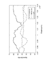
- FIG. 9 is a fourth graph showing the power spectrum of the road surface profile estimated by the road surface profile estimation system 1 according to the first embodiment of the present invention.
- the horizontal axis indicates the frequency (cycle) in units of cycles / meter (cycle / m), and the vertical axis indicates the power spectrum density (PS) of the road surface profile m 2 / (cycle / m). It is shown in units.
- the power spectrum density of the road surface profile estimated by the road surface profile estimation system 1 according to the present embodiment using a light vehicle (Light) is shown by a solid line, and this operation is performed using a small vehicle (Small size).
- the power spectrum density of the road surface profile estimated by the road surface profile estimation system 1 according to the embodiment is indicated by an alternate long and short dash line, and the road surface profile estimated by the road surface profile estimation system 1 according to the present embodiment using a medium size vehicle is used.
- the power spectrum density is indicated by a two-dot chain line, and the power spectrum density of the road surface profile estimated using a dedicated vehicle (Profiler) is indicated by a broken line.
- Profile dedicated vehicle
- FIG. 10 is a fifth graph showing the travel distance and speed of the vehicle 30 when the road surface profile is estimated by the road surface profile estimation system 1 according to the first embodiment of the present invention.
- the horizontal axis indicates the travel distance (Distance) in units of meters (m)
- the vertical axis indicates the speed of the vehicle 30 in units of kilometers per hour (km / h).
- the speed of a light vehicle (Light) is indicated by a solid line
- the speed of a small vehicle (Small size) is indicated by a one-dot chain line
- the speed of a medium-sized vehicle (Middle size) is indicated by a two-dot chain line.
- the road surface profile estimation system 1 stably estimates the road surface profile.
- the road surface profile can be accurately estimated regardless of the size and traveling speed of the vehicle 30 in which the smartphone 20 incorporating the accelerometer 21 and the angular velocity meter 22 is installed. Can do.
- FIG. 11 is a sixth graph showing the travel distance and speed of the vehicle 30 when the road surface profile is estimated by the road surface profile estimation system 1 according to the first embodiment of the present invention.
- the abscissa indicates the travel distance (Distance) in units of meters (m)
- the ordinate indicates the road profile index IRI in units of millimeters / meters (mm / m).
- IRI estimated by the road surface profile estimation system 1 according to the present embodiment using a light vehicle (Light) is shown by a solid line
- IRI estimated by using a dedicated vehicle is shown by a broken line.
- the difference between the IRI estimated by the road surface profile estimation system 1 according to the present embodiment and the IRI estimated using the dedicated vehicle is concentrated at the location where the dedicated vehicle has stopped, and the dedicated vehicle has a high speed. Considering that it is designed for measurement during driving and the IRI of the road surface may not be accurately estimated before and after the stop, the IRI estimated using the dedicated vehicle is It is thought that there is a deviation from the true value before and after. According to the road surface profile estimation system 1 according to the present embodiment, it is possible to accurately estimate the IRI of the road surface even when the vehicle 30 stops. According to the road surface profile estimation system 1 according to the present embodiment, it is possible to accurately estimate the road surface profile even on a general road where frequent stopping is inevitable.
- the simulation model M1 and the observation model M2 stored in the storage unit 18 of the road surface profile estimation apparatus 10 are different from those in the first embodiment.
- the road surface profile estimation system 1 according to the second embodiment has the same configuration as the road surface profile estimation system according to the first embodiment.
- the simulation model M1 is a model that represents the time evolution of the state variable by linear transformation or nonlinear transformation of the state variable and Gaussian noise or non-Gaussian noise
- the observation model M2 is the state By calculating the linear transformation or nonlinear transformation of the variable and Gaussian noise or non-Gaussian noise, the acceleration in the vertical direction with respect to the road surface on which the vehicle 30 contacts is calculated, the angular velocity with respect to the pitch axis of the vehicle 30, the displacement in the vertical direction, and the angular displacement with respect to the pitch axis Model.
- the prediction unit 13, the second calculation unit 14, and the update unit 15 of the road surface profile estimation device 10 according to the present embodiment function as a particle filter.
- FIG. 12 is a flowchart of the third process executed by the road surface profile estimation apparatus 10 according to the second embodiment of the present invention.
- the third process is a process in which the road surface profile estimation apparatus 10 performs data assimilation of the state variable and the measured value by the particle filter.
- the road surface profile estimation device 10 acquires the acceleration in the vertical direction and the angular velocity related to the pitch axis with respect to the road surface on which the vehicle 30 comes into contact with the acquisition unit 11 (S30).
- the acceleration measurement by the accelerometer 21 and the angular velocity measurement by the angular velocity meter 22 may be performed at predetermined time intervals.
- the acquisition unit 11 may acquire the acceleration and the angular velocity every time measurement is performed by the accelerometer 21 and the angular velocity meter 22, or may acquire the acceleration and the angular velocity collectively after the measurement is completed.
- the first calculation unit 12 integrates the acceleration acquired by the acquisition unit 11 to calculate the vertical displacement, and integrates the angular velocity to calculate the angular displacement related to the pitch axis (S31).
- the acceleration and angular velocity acquired by the acquisition unit 11 and the displacement and angular displacement calculated by the first calculation unit 12 are collectively expressed as a vector y.
- the prediction unit 13 predicts the time evolution of the state variable based on the half-car model, and generates a plurality of particles based on the predicted probability distribution of the state variable (S32).
- the time evolution of the state variable is obtained by a simulation model M1 represented by the following formula (32).
- f k is a linear transformation or a nonlinear transformation of the state variable x k at time step k.
- w (k) is a noise term at time step k, and is averaged Gaussian noise or non-Gaussian noise.
- the prediction unit 13 generates N particles x k-1 (i) based on the probability distribution p (x k-1
- x k (i) is obtained, and the predicted probability distribution p (x k
- ⁇ represents a delta function.
- I 1, 2,... N.
- y 1: 1 ) may be assumed to be a uniform distribution, for example, and p (x 2
- the initial condition may be other than the uniform distribution, and an arbitrary distribution can be assumed.
- the second calculation unit 14 calculates acceleration, angular velocity, displacement, and angular displacement from the state variables predicted by the prediction unit 13 based on the observation model M2, and calculates a weight for updating (S33).
- the second calculation unit 14 calculates acceleration, angular velocity, displacement, and angular displacement y k from the state variable x k predicted by the prediction unit 13 based on the observation model M2 represented by the following mathematical formula (33). .
- h k is a linear transformation or a nonlinear transformation of the state variable x k at time step k.
- ⁇ (k) is a noise term at time step k, and is an average of 0 Gaussian noise or non-Gaussian noise.
- the second calculator 14 calculates the probability distribution p (y k
- the updating unit 15 resamples particles with the calculated weight q i and updates the probability distribution of the state variable (S34).
- the update unit 15 obtains the probability distribution p (x k
- the estimation unit 17 estimates a road surface profile based on the state variable probability distribution p (x k
- the estimation unit 17 may estimate a road surface profile by obtaining an expected value of a variable representing road surface unevenness included in the state variable.
- the time evolution of the state variable is represented by the simulation model M1 including nonlinear transformation and non-Gaussian noise
- the observation is represented by the observation model M2 including nonlinear transformation and non-Gaussian noise.
Landscapes
- Engineering & Computer Science (AREA)
- Physics & Mathematics (AREA)
- General Physics & Mathematics (AREA)
- Multimedia (AREA)
- Radar, Positioning & Navigation (AREA)
- Remote Sensing (AREA)
- Structural Engineering (AREA)
- Architecture (AREA)
- Civil Engineering (AREA)
- Mathematical Physics (AREA)
- Transportation (AREA)
- Mechanical Engineering (AREA)
- Automation & Control Theory (AREA)
- Control Of Driving Devices And Active Controlling Of Vehicle (AREA)
- Length Measuring Devices With Unspecified Measuring Means (AREA)
- Length Measuring Devices By Optical Means (AREA)
- Image Processing (AREA)
Abstract
一般道路を含む任意の路面のプロファイルを、汎用の車両を用いて精度良く推定することのできる路面プロファイル推定装置等を提供する。路面プロファイル推定装置10は、垂直方向の加速度及びピッチ軸に関する角速度を取得する取得部11と、垂直方向の変位を算出し、ピッチ軸に関する角度変位を算出する第1算出部12と、シミュレーションモデルに基づいて、車両の状態変数の時間発展を予測する予測部13と、観測モデルに基づいて、状態変数から、加速度、角速度、変位及び角度変位を算出する第2算出部14と、取得部11により取得された加速度及び角速度並びに第1算出部12により算出された変位及び角度変位と、第2算出部14により算出された加速度、角速度、変位及び角度変位とのデータ同化によって、状態変数を更新する更新部15と、状態変数に基づいて、路面のプロファイルを推定する推定部17と、を備える。
Description
本発明は、路面プロファイル推定装置、路面プロファイル推定システム、路面プロファイル推定方法及び路面プロファイル推定プログラムに関する。
に関する。
に関する。
従来、路面の縦断形状(以下、路面のプロファイルという。)を評価するために、路面の凹凸を測定し、例えばIRI(International Roughness Index:国際ラフネス指数)等の指数を算出する場合がある。路面プロファイルに関する情報は、路面の補修要否を判断したり、車両で走行した場合の快適性を評価したりするために用いられることがある。
特開2017-040486号公報には、自転車に取り付けられた速度センサ、加速度センサ、角速度センサによって計測したデータに基づいて、自転車の走行距離及び鉛直方向変位を求め、走行距離と加速度に基づく鉛直方向変位を互いに関連付けるか、又は、加速度に基づく鉛直方向変位及び角速度に基づく鉛直方向変位を組み合わせて走行距離と関連付けることによって、自転車道の路面プロファイルを求める測定装置が記載されている。
路面プロファイルは、高精度なレーザ距離計を備えた専用車によって推定されることがある。しかしながら、路面プロファイルを推定する専用車は高価であり、使用することのできる事業者が限られていた。また、路面プロファイルを推定する専用車は、高速道路の路面プロファイルを推定することを前提として設計されることがあり、一般道路の路面プロファイルの推定に必ずしも適していない場合があった。
一方、汎用の車両に簡易なセンサを取り付けて路面プロファイルを推定する場合もあったが、十分な精度が得られないことがあった。
そこで、本発明は、一般道路を含む任意の路面のプロファイルを、汎用の車両を用いて精度良く推定することのできる路面プロファイル推定装置、路面プロファイル推定システム、路面プロファイル推定方法及び路面プロファイル推定プログラムを提供する。
本発明の一態様に係る路面プロファイル推定装置は、車両が接地する路面に対して垂直方向の加速度及びピッチ軸に関する角速度を取得する取得部と、加速度を積分して垂直方向の変位を算出し、角速度を積分してピッチ軸に関する角度変位を算出する第1算出部と、シミュレーションモデルに基づいて、車両が走行する路面の凹凸を表す変数、車両の上下運動を表す変数及び車両のピッチ軸に関する回転運動を表す変数を含む状態変数の時間発展を予測する予測部と、観測モデルに基づいて、予測部により予測された状態変数から、加速度、角速度、変位及び角度変位を算出する第2算出部と、取得部により取得された加速度及び角速度並びに第1算出部により算出された変位及び角度変位と、第2算出部により算出された加速度、角速度、変位及び角度変位とのデータ同化によって、状態変数を更新する更新部と、状態変数に含まれる路面の凹凸を表す変数に基づいて、路面のプロファイルを推定する推定部と、を備える。
この態様によれば、車両が接地する路面に対して垂直方向の加速度及びピッチ軸に関する角速度のみならず、垂直方向の変位及びピッチ軸に関する角度変位をデータ同化に用いることで、安定性の高い解析を実現することができ、一般道路を含む任意の路面のプロファイルを、汎用の車両を用いて精度良く推定することができる。
上記態様において、予測部により予測される時点よりも後に取得部により取得された加速度及び角速度並びに第1算出部により算出された変位及び角度変位に基づいて、状態変数を平滑化する平滑部をさらに備えてもよい。
この態様によれば、車両の垂直方向の加速度及びピッチ軸に関する角速度のみならず、垂直方向の変位及びピッチ軸に関する角度変位をデータの平滑化に用いることで、さらに精度良く路面のプロファイルを推定することができる。
上記態様において、シミュレーションモデルは、車両のハーフカーモデルであり、
状態変数は、ハーフカーモデルの状態を表す変数であってよい。
状態変数は、ハーフカーモデルの状態を表す変数であってよい。
この態様によれば、シミュレーションモデルとしてクォーターカーモデルを用いる場合に比べて、車両の運動状態をより正確に表すことができ、状態変数の時間発展をより精度良く予測することができる。
上記態様において、路面の凹凸を表す変数は、ハーフカーモデルのフロントタイヤの垂直方向の変位及び速度と、ハーフカーモデルのリアタイヤの垂直方向の変位及び速度とを含み、車両の上下運動を表す変数は、ハーフカーモデルの重心の垂直方向の変位及び速度と、ハーフカーモデルのフロントサスペンションの垂直方向の変位及び速度と、ハーフカーモデルのリアサスペンションの垂直方向の変位及び速度とを含み、車両のピッチ軸に関する回転運動を表す変数は、ハーフカーモデルの重心を通るピッチ軸に関する回転角及び角速度を含んでよい。
上記態様において、シミュレーションモデルは、状態変数の線形変換又は非線形変換とガウシアンノイズ又は非ガウシアンノイズによって状態変数の時間発展を表すモデルであり、観測モデルは、状態変数の線形変換又は非線形変換とガウシアンノイズ又は非ガウシアンノイズによって、加速度、角速度、変位及び角度変位を算出するモデルであってよい。
この態様によれば、非線形変換と非ガウシアンノイズを含むシミュレーションモデルによって状態変数の時間発展を表し、非線形変換と非ガウシアンノイズを含む観測モデルによって観測を表すことで、非線形の挙動や非ガウシアンの揺動を正確に記述することができ、路面プロファイルをより精度良く推定することができる。
上記態様において、シミュレーションモデルは、状態変数の線形変換とガウシアンノイズによって状態変数の時間発展を表すモデルであり、観測モデルは、状態変数の線形変換とガウシアンノイズによって、加速度、角速度、変位及び角度変位を算出するモデルであり、更新部は、状態変数の2乗誤差を最小化するように、状態変数を更新してよい。
この態様によれば、線形変換とガウシアンノイズを含むシミュレーションモデルによって状態変数の時間発展を表し、線形変換とガウシアンノイズを含む観測モデルによって観測を表すことで、比較的負荷の軽い演算によって路面プロファイルを推定することができる。
本発明の他の態様に係る路面プロファイル推定システムは、車両に設置され、車両が接地する路面に対して垂直方向の加速度を測定する加速度計と、車両に設置され、車両のピッチ軸に関する角速度を測定する角速度計と、車両が走行する路面のプロファイルを推定する路面プロファイル推定装置と、を含み、路面プロファイル推定装置は、加速度計から加速度を取得し、角速度計から角速度を取得する取得部と、加速度を積分して垂直方向の変位を算出し、角速度を積分してピッチ軸に関する角度変位を算出する第1算出部と、シミュレーションモデルに基づいて、車両が走行する路面の凹凸を表す変数、車両の上下運動を表す変数及び車両のピッチ軸に関する回転運動を表す変数を含む状態変数の時間発展を予測する予測部と、観測モデルに基づいて、予測部により予測された状態変数から、加速度、角速度、変位及び角度変位を算出する第2算出部と、取得部により取得された加速度及び角速度並びに第1算出部により算出された変位及び角度変位と、第2算出部により算出された加速度、角速度、変位及び角度変位とのデータ同化によって、状態変数を更新する更新部と、状態変数に含まれる路面の凹凸を表す変数に基づいて、路面のプロファイルを推定する推定部と、を備える。
この態様によれば、車両が接地する路面に対して垂直方向の加速度及びピッチ軸に関する角速度のみならず、垂直方向の変位及びピッチ軸に関する角度変位をデータ同化に用いることで、安定性の高い解析を実現することができ、一般道路を含む任意の路面のプロファイルを、汎用の車両を用いて精度良く推定することができる。
本発明の他の態様に係る路面プロファイル推定装置方法は、車両が接地する路面に対して垂直方向の加速度及びピッチ軸に関する角速度を取得する第1ステップと、加速度を積分して垂直方向の変位を算出し、角速度を積分してピッチ軸に関する角度変位を算出する第2ステップと、シミュレーションモデルに基づいて、車両が走行する路面の凹凸を表す変数、車両の上下運動を表す変数及び車両のピッチ軸に関する回転運動を表す変数を含む状態変数の時間発展を予測する第3ステップと、観測モデルに基づいて、第3ステップにおいて予測された状態変数から、加速度、角速度、変位及び角度変位を算出する第4ステップと、第1ステップにおいて取得された加速度及び角速度並びに第2ステップにおいて算出された変位及び角度変位と、第4ステップにおいて算出された加速度、角速度、変位及び角度変位とのデータ同化によって、状態変数を更新する第5ステップと、状態変数に含まれる路面の凹凸を表す変数に基づいて、路面のプロファイルを推定する第6ステップと、を含む。
この態様によれば、車両が接地する路面に対して垂直方向の加速度及びピッチ軸に関する角速度のみならず、垂直方向の変位及びピッチ軸に関する角度変位をデータ同化に用いることで、安定性の高い解析を実現することができ、一般道路を含む任意の路面のプロファイルを、汎用の車両を用いて精度良く推定することができる。
本発明の他の態様に係る路面プロファイル推定装置プログラムは、路面プロファイル推定装置に備えられたコンピュータを、車両が接地する路面に対して垂直方向の加速度及びピッチ軸に関する角速度を取得する取得部、加速度を積分して垂直方向の変位を算出し、角速度を積分してピッチ軸に関する角度変位を算出する第1算出部、シミュレーションモデルに基づいて、車両が走行する路面の凹凸を表す変数、車両の上下運動を表す変数及び車両のピッチ軸に関する回転運動を表す変数を含む状態変数の時間発展を予測する予測部、観測モデルに基づいて、予測部により予測された状態変数から、加速度、角速度、変位及び角度変位を算出する第2算出部、取得部により取得された加速度及び角速度並びに第1算出部により算出された変位及び角度変位と、第2算出部により算出された加速度、角速度、変位及び角度変位とのデータ同化によって、状態変数を更新する更新部、及び状態変数に含まれる路面の凹凸を表す変数に基づいて、路面のプロファイルを推定する推定部、として機能させる。
この態様によれば、車両が接地する路面に対して垂直方向の加速度及びピッチ軸に関する角速度のみならず、垂直方向の変位及びピッチ軸に関する角度変位をデータ同化に用いることで、安定性の高い解析を実現することができ、一般道路を含む任意の路面のプロファイルを、汎用の車両を用いて精度良く推定することができる。
本発明によれば、一般道路を含む任意の路面のプロファイルを、汎用の車両を用いて精度良く推定することのできる路面プロファイル推定装置、路面プロファイル推定システム、路面プロファイル推定方法及び路面プロファイル推定プログラムを提供することができる。
添付図面を参照して、本発明の実施形態について説明する。なお、各図において、同一の符号を付したものは、同一又は同様の構成を有する。
[第1実施形態]
図1は、本発明の第1実施形態に係る路面プロファイル推定システム1の概略図である。路面プロファイル推定システム1は、車両30と、車両30が接地する路面に対して垂直方向の加速度を測定する加速度計21と、車両30のピッチ軸に関する角速度を測定する角速度計22と、車両30が走行する路面のプロファイルを推定する路面プロファイル推定装置10と、を含む。本実施形態に係る路面プロファイル推定システム1において、加速度計21及び角速度計22は、スマートフォン20に内蔵されたものである。スマートフォン20は、車両30のダッシュボードやトランクルーム等、任意の場所に設置されてよい。もっとも、加速度計21及び角速度計22は、独立して車両30に設置されるものであってもよい。加速度計21は、車両30が接地する路面に対して垂直方向の加速度を測定するが、必ずしも垂直方向の加速度のみを測定するものでなくてもよく、路面に対して水平方向の加速度をも測定するものであってよい。加速度計21は、車両30の加速度の複数の成分のうち、少なくとも路面に対して垂直方向の成分を測定するものであればよい。角速度計22は、車両30のピッチ軸に関する角速度を測定するが、必ずしもピッチ軸に関する角速度のみを測定するものでなくてもよく、車両30のロール軸に関する角速度やヨー軸に関する角速度をも測定するものであってよい。角速度計22は、車両30の複数の軸に関する角速度のうち、少なくともピッチ軸に関する角速度を測定するものであればよい。
図1は、本発明の第1実施形態に係る路面プロファイル推定システム1の概略図である。路面プロファイル推定システム1は、車両30と、車両30が接地する路面に対して垂直方向の加速度を測定する加速度計21と、車両30のピッチ軸に関する角速度を測定する角速度計22と、車両30が走行する路面のプロファイルを推定する路面プロファイル推定装置10と、を含む。本実施形態に係る路面プロファイル推定システム1において、加速度計21及び角速度計22は、スマートフォン20に内蔵されたものである。スマートフォン20は、車両30のダッシュボードやトランクルーム等、任意の場所に設置されてよい。もっとも、加速度計21及び角速度計22は、独立して車両30に設置されるものであってもよい。加速度計21は、車両30が接地する路面に対して垂直方向の加速度を測定するが、必ずしも垂直方向の加速度のみを測定するものでなくてもよく、路面に対して水平方向の加速度をも測定するものであってよい。加速度計21は、車両30の加速度の複数の成分のうち、少なくとも路面に対して垂直方向の成分を測定するものであればよい。角速度計22は、車両30のピッチ軸に関する角速度を測定するが、必ずしもピッチ軸に関する角速度のみを測定するものでなくてもよく、車両30のロール軸に関する角速度やヨー軸に関する角速度をも測定するものであってよい。角速度計22は、車両30の複数の軸に関する角速度のうち、少なくともピッチ軸に関する角速度を測定するものであればよい。
路面プロファイル推定装置10は、加速度計21及び角速度計22によって測定した加速度及び角速度等に基づいて、車両30が走行する路面のプロファイルを推定する。本実施形態に係る路面プロファイル推定システム1において、路面プロファイル推定装置10は、通信ネットワークNを介してスマートフォン20と接続される。ここで、通信ネットワークNは、有線又は無線の通信網であってよい。なお、路面プロファイル推定装置10は、必ずしもスマートフォン20と独立した装置でなくてもよく、スマートフォン20と一体となって構成されるものであってもよい。その場合、スマートフォン20にインストールされた路面推定プログラムが実行されることで、スマートフォン20が路面プロファイル推定装置10として機能してよい。
車両30は、路面上を4輪のタイヤで走行する自動車であってよい。もっとも、車両30は、3輪や2輪のものであってもよいし、5輪以上のものであってもよい。車両30としては任意の大きさの自動車を用いてよく、本明細書では、軽車両(Light)、小型車両(Small)及び中型車両(Middle)を車両30として用いた場合について説明する。
図2は、本発明の第1実施形態に係る路面プロファイル推定装置10の機能ブロック図である。路面プロファイル推定装置10は、取得部11、第1算出部12、予測部13、第2算出部14、更新部15、平滑化部16、推定部17及び記憶部18を備える。
取得部11は、車両30が接地する路面に対して垂直方向の加速度及びピッチ軸に関する角速度を取得する。取得部11は、スマートフォン20と通信して、スマートフォン20に内蔵された加速度計21から加速度を取得し、角速度計22から角速度を取得してよい。
第1算出部12は、加速度を積分して垂直方向の変位を算出し、角速度を積分してピッチ軸に関する角度変位を算出する。第1算出部12は、取得部11により取得された加速度を、時間に関して2階積分することで垂直方向の変位を算出する。また、第1算出部12は、取得部11により取得された角速度を、時間に関して1階積分することでピッチ軸に関する角度変位を算出する。
予測部13は、シミュレーションモデルM1に基づいて、車両30が走行する路面の凹凸を表す変数、車両30の上下運動を表す変数及び車両30のピッチ軸に関する回転運動を表す変数を含む状態変数の時間発展を予測する。ここで、シミュレーションモデルM1は、記憶部18に記憶されている。本実施形態では、シミュレーションモデルM1は、車両30のハーフカーモデルであり、状態変数は、ハーフカーモデルの状態を表す変数である。より具体的には、路面の凹凸を表す変数は、ハーフカーモデルのフロントタイヤの垂直方向の変位及び速度と、ハーフカーモデルのリアタイヤの垂直方向の変位及び速度とを含む。また、車両30の上下運動を表す変数は、ハーフカーモデルの重心の垂直方向の変位及び速度と、ハーフカーモデルのフロントサスペンションの垂直方向の変位及び速度と、ハーフカーモデルのリアサスペンションの垂直方向の変位及び速度とを含む。また、車両30のピッチ軸に関する回転運動を表す変数は、ハーフカーモデルの重心を通るピッチ軸に関する回転角及び角速度を含む。
第2算出部14は、観測モデルM2に基づいて、予測部13により予測された状態変数から、車両30の接地する路面に対して垂直方向の加速度、ピッチ軸に関する角速度、垂直方向の変位及びピッチ軸に関する角度変位を算出する。観測モデルM2は記憶部18に記憶されている。
更新部15は、取得部11により取得された加速度及び角速度並びに第1算出部12により算出された変位及び角度変位と、第2算出部14により算出された加速度、角速度、変位及び角度変位とのデータ同化によって、状態変数を更新する。ここで、データ同化とは、シミュレーションモデルM1によって予測された状態変数を、実際の測定値に基づいて更新して、予測精度を高める処理をいう。データ同化の具体的な例については、後に詳細に説明する。
平滑化部16は、予測部13により予測される時点よりも後に取得部11により取得された加速度及び角速度並びに第1算出部12により算出された変位及び角度変位に基づいて、状態変数を平滑化する。
推定部17は、状態変数に含まれる路面の凹凸を表す変数に基づいて、路面のプロファイルを推定する。ここで、路面のプロファイルとは、路面の縦断形状をいう。
記憶部18は、シミュレーションモデルM1及び観測モデルM2を記憶する。本実施形態に係る路面プロファイル推定装置10において、シミュレーションモデルM1は、状態変数の線形変換とガウシアンノイズによって状態変数の時間発展を表すモデルであり、観測モデルM2は、状態変数の線形変換とガウシアンノイズによって、車両30の接地する路面に対して垂直方向の加速度、車両30のピッチ軸に関する角速度、垂直方向の変位及びピッチ軸に関する角度変位を算出するモデルである。また、更新部15は、状態変数の2乗誤差を最小化するように、状態変数を更新する。後に詳細に説明するように、本実施形態に係る路面プロファイル推定装置10の予測部13、第2算出部14及び更新部15は、カルマンフィルタとして機能する。
図3は、本発明の第1実施形態に係る路面プロファイル推定装置10により用いられるシミュレーションモデルM1の概念図である。シミュレーションモデルM1は、ハーフカーモデルであり、12の状態変数と13のパラメータを含む。
状態変数は、ハーフカーモデルのフロントタイヤの垂直方向の変位hf及び速度dhf/dtと、ハーフカーモデルのリアタイヤの垂直方向の変位hr及び速度とdhr/dtと、ハーフカーモデルの重心の垂直方向の変位ub及び速度dub/dtと、ハーフカーモデルのフロントサスペンションの垂直方向の変位uf及び速度duf/dtと、ハーフカーモデルのリアサスペンションの垂直方向の変位ur及び速度dur/dtと、ハーフカーモデルの重心を通るピッチ軸に関する回転角θ及び角速度dθ/dtと、を含む。
パラメータは、ハーフカーモデルのフロントタイヤのばね係数ktfと、フロントタイヤの質量mfと、フロントサスペンションのばね係数kf及び減衰係数cfと、ハーフカーモデルのリアタイヤのばね係数ktrと、リアタイヤの質量mrと、リアサスペンションのばね係数kr及び減衰係数crと、ハーフカーモデルの車体の質量mb及びピッチ軸まわりの慣性モーメントIyと、ハーフカーモデルの重心からフロントタイヤの接地点までの水平距離Lfと、ハーフカーモデルの重心からリアタイヤの接地点までの水平距離Lrと、フロントタイヤの接地点から加速度計21及び角速度計22の設置点までの水平距離dと、を含む。
シミュレーションモデルM1としてハーフカーモデルを用いることで、クォーターカーモデルを用いる場合に比べて、車両30の運動状態をより正確に表すことができ、状態変数の時間発展をより精度良く予測することができる。
図4は、本発明の第1実施形態に係る路面プロファイル推定装置10により実行される第1処理のフローチャートである。第1処理は、路面プロファイル推定装置10によって、状態変数と測定値とのカルマンフィルタによるデータ同化を行う処理である。
路面プロファイル推定装置10は、取得部11により、車両30の接地する路面に対して垂直方向の加速度及びピッチ軸に関する角速度を取得する(S10)。加速度計21による加速度の測定と、角速度計22による角速度の測定は、所定の時間間隔毎に行われてよい。取得部11は、加速度計21及び角速度計22によって測定が行われる度に加速度及び角速度を取得してもよいし、測定終了後に加速度及び角速度をまとめて取得してもよい。
第1算出部12は、取得部11により取得した加速度を積分して垂直方向の変位を算出し、角速度を積分してピッチ軸に関する角度変位を算出する(S11)。取得部11により取得した加速度及び角速度並びに第1算出部12により算出した変位及び角度変位をまとめて、ベクトルyで表すこととする。
予測部13は、ハーフカーモデルに基づいて、状態変数の時間発展を予測する(S12)。状態変数の時間発展は、以下の数式(1)で表される運動方程式に基づいて求められる。
ここで、ベクトルUは、以下の数式(2)で表される。ベクトルUは、ハーフカーモデルの重心の垂直方向の変位ub、重心を通るピッチ軸に関する角度変位θ、ハーフカーモデルのフロントサスペンションの垂直方向の変位uf及びハーフカーモデルのリアサスペンションの垂直方向の変位urを、ベクトルの成分として含む。
また、行列M、C及びKは、それぞれ以下の数式(3)~(5)で与えられ、パラメータに依存する量である。


また、数式(1)の右辺は、路面の凹凸を表す変数に依存するベクトルPで与えられる。ベクトルPは、以下の数式(6)で与えられる。
以下の説明では、数式(7)に示すように、12の状態変数をベクトルxaによって表す。
予測部13は、車両30の挙動をハーフカーモデルによってモデル化したことで生じ得る誤差を、ノイズ項によって表す。予測部13は、状態変数xaの時間発展を、以下の数式(8)によって求める。
ここで、状態変数xaの下付き添え字「k」や「k+1」は、時間ステップを表す。右辺の行列Aaは、数式(1)で表される状態変数の時間発展を、単位時間ステップにおける線形変換として表したものである。Aa=exp(AΔt)と表すとき、Aは以下の数式(9)で表される。ただし、Δtは、単位時間ステップを表す。

ここで、行列M、C及びKは、数式(3)~(5)に示したものである。I4×4は、4×4の単位行列であり、行列O4×4、O4×2、O2×2は、それぞれ4×4、4×2、2×2の零行列である。また、行列Zは、以下の数式(10)で表される量であり、行列Tは、以下の数式(11)で表される量である。

また、数式(8)の右辺のζkは、時間ステップkにおけるノイズ項である。ノイズ項ζkは、以下の数式(12)で表されるように、8次元ベクトルwkと4次元ベクトルηkを含む。
ノイズ項ζkのうち、ハーフカーモデルの重心の垂直方向の変位ub及び速度dub/dtと、ハーフカーモデルのフロントサスペンションの垂直方向の変位uf及び速度duf/dtと、ハーフカーモデルのリアサスペンションの垂直方向の変位ur及び速度dur/dtと、ハーフカーモデルの重心を通るピッチ軸に関する回転角θ及び角速度dθ/dtと、に対するノイズ項wkは、平均が0、分散共分散行列がQのガウシアンノイズである。なお、δk,lは、クロネッカーのデルタである。
また、ノイズ項ζkのうち、ハーフカーモデルのフロントタイヤの垂直方向の変位hf及び速度dhf/dtと、ハーフカーモデルのリアタイヤの垂直方向の変位hr及び速度とdhr/dtと、に対するノイズ項ηkは、平均が0、分散共分散行列がSのガウシアンノイズである。

なお、状態変数の時間発展を表す数式(8)から明らかなように、ハーフカーモデルのフロントタイヤの垂直方向の変位hf及び速度dhf/dtと、ハーフカーモデルのリアタイヤの垂直方向の変位hr及び速度とdhr/dtと、をまとめた4次元ベクトルuの時間発展は、以下の数式(15)のように与えられる。
第2算出部14は、観測モデルM2に基づいて、予測部13により予測された状態変数から、加速度、角速度、変位及び角度変位を算出する(S13)。第2算出部14は、以下の数式(16)で表される観測モデルM2に基づいて、予測部13により予測された状態変数xaから、加速度、角速度、変位及び角度変位をまとめたベクトルyを算出する。第2算出部14は、状態変数の線形変換Caによって観測をモデル化し、観測誤差をノイズ項vkによってモデル化する。
ここで、線形変換Caは、以下の数式(17)で与えられる。ここで、O4は、4×4の零行列である。
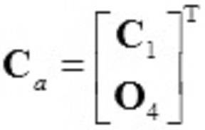
行列C1は、以下の数式(18)で与えられる。
また、数式(14)の右辺のノイズ項vkは、平均が0、分散共分散行列がRのガウシアンノイズである。
更新部15は、最適カルマンゲインにより、状態変数を更新する(S14)。ここで、最適カルマンゲインとは、状態変数の2乗誤差を最小化するように定められる更新の係数であり、以下の数式(20)で与えられる。
数式(20)の右辺のPk+1
-は、時間ステップk+1における更新前の状態変数の分散である。状態変数は、期待値の初期値が以下の数式(21)によって与えられ、分散の初期値が以下の数式(22)によって与えられる。なお、ハット記号付きの状態変数xaは、推定値であることを表している。
前述のように、状態変数xaの期待値の時間発展は、以下の数式(23)によって与えられる。
ここで、上付き添え字「-」は、更新前の量であることを表している。また、状態変数xaの分散の時間発展は、以下の数式(24)によって与えられる。
更新部15は、更新後の状態変数xaの期待値を以下の数式(25)によって求める。
ここで、右辺の「yk+1」は、時間ステップk+1において、取得部11により取得された加速度及び角速度並びに第1算出部12によって算出された変位度及び角度変位であり、車両30について実際に測定された値である。右辺の第2項は、測定値yk+1と状態変数xk+1
a-から算出される観測値との差に対して最適カルマンゲインGk+1を乗じた値によって状態変数を修正する項である。
更新部15は、更新後の状態変数xaの分散を以下の数式(26)によって求める。
以上のように、時間ステップ毎に、状態変数を予測して、測定値との差に応じて更新することで、精度良く状態変数を推定することができる。線形変換とガウシアンノイズを含むシミュレーションモデルM1によって状態変数の時間発展を表し、線形変換とガウシアンノイズを含む観測モデルM2によって観測を表すことで、比較的負荷の軽い演算によって路面プロファイルを推定することができる。
図5は、本発明の第1実施形態に係る路面プロファイル推定装置10により実行される第2処理のフローチャートである。第2処理は、路面プロファイル推定装置10によって状態変数の平滑化処理を行い、路面プロファイルの推定を行う処理である。
平滑化部16は、はじめに平滑化を行う区間の指定を受け付ける(S20)。平滑化部16は、時間ステップがk=0からk=Tまで存在する場合に、時間ステップkの状態変数xkの平滑化のために、その後の全ての状態変数xk+1,xk+2,…xTを用いてよい。もっとも、区間L(Lは任意の自然数)を指定し、xk+1,xk+2,…xk+Lを用いて状態変数の平滑化を行うこととしてもよい。
平滑化部16は、以下の数式(27)によって平滑化後の状態変数の期待値の初期化を行い、以下の数式(28)によって平滑化後の状態変数の分散の初期化を行う。
次に、平滑化部16は、以下の数式(29)によって、平滑化処理における逆伝播のゲインΦを算出する(S21)。
平滑化部16は、ゲインΦに基づいて、以下の数式(30)によって、状態変数の期待値を時間ステップk=Tから過去に向かって平滑化する。また、平滑化部16は、以下の数式(31)によって、状態変数の分散を平滑化する(S22)。
以上により、状態変数の平滑化が行われる。その後、推定部17は、状態変数に含まれる路面の凹凸を表す変数に基づいて、路面のプロファイルを推定する(S23)。具体的には、推定部17は、ハーフカーモデルのフロントタイヤの垂直方向の変位hfと、ハーフカーモデルのリアタイヤの垂直方向の変位hrとに基づいて、路面のプロファイルを推定する。
本実施形態に係る路面プロファイル推定装置10によれば、車両30が接地する路面に対して垂直方向の加速度及びピッチ軸に関する角速度のみならず、垂直方向の変位及びピッチ軸に関する角度変位をデータ同化に用いることで、安定性の高い解析を実現することができ、一般道路を含む任意の路面のプロファイルを、汎用の車両を用いて精度良く推定することができる。また、垂直方向の加速度及びピッチ軸に関する角速度のみならず、垂直方向の変位及びピッチ軸に関する角度変位をデータの平滑化に用いることで、さらに精度良く路面のプロファイルを推定することができる。
図6は、本発明の第1実施形態に係る路面プロファイル推定システム1により推定された、走行距離と路面プロファイルの関係を示す第1グラフである。同図では、横軸に走行距離(Distance)をメートル(m)の単位で示し、縦軸に路面プロファイルをメートル(m)の単位で示している。第1グラフには、軽車両(Light)を用いて本実施形態に係る路面プロファイル推定システム1によって推定された路面プロファイルを実線で示し、専用車(Profiler)を用いて推定された路面プロファイルを破線で示している。第1グラフから、軽車両を用いて本実施形態に係る路面プロファイル推定システム1によって推定された路面プロファイルと、専用車を用いて推定された路面プロファイルとがほとんど一致していることが読み取れる。本実施形態に係る路面プロファイル推定システム1によれば、軽車両とスマートフォン20を用いることで、専用車と同程度の精度で路面プロファイルを推定できる。
図7は、本発明の第1実施形態に係る路面プロファイル推定システム1により推定された、走行距離と路面プロファイルの関係を示す第2グラフである。同図では、横軸に走行距離(Distance)をメートル(m)の単位で示し、縦軸に路面プロファイルをメートル(m)の単位で示している。第2グラフには、小型車両(Small size)を用いて本実施形態に係る路面プロファイル推定システム1によって推定された路面プロファイルを一点鎖線で示し、専用車(Profiler)を用いて推定された路面プロファイルを破線で示している。第2グラフから、小型車両を用いて本実施形態に係る路面プロファイル推定システム1によって推定された路面プロファイルと、専用車を用いて推定された路面プロファイルとがほとんど一致していることが読み取れる。本実施形態に係る路面プロファイル推定システム1によれば、小型車両とスマートフォン20を用いることで、専用車と同程度の精度で路面プロファイルを推定できる。
図8は、本発明の第1実施形態に係る路面プロファイル推定システム1により推定された、走行距離と路面プロファイルの関係を示す第3グラフである。同図では、横軸に走行距離(Distance)をメートル(m)の単位で示し、縦軸に路面プロファイルをメートル(m)の単位で示している。第3グラフには、中型車両(Middle size)を用いて本実施形態に係る路面プロファイル推定システム1によって推定された路面プロファイルを二点鎖線で示し、専用車(Profiler)を用いて推定された路面プロファイルを破線で示している。第3グラフから、中型車両を用いて本実施形態に係る路面プロファイル推定システム1によって推定された路面プロファイルと、専用車を用いて推定された路面プロファイルとがほとんど一致していることが読み取れる。本実施形態に係る路面プロファイル推定システム1によれば、中型車両とスマートフォン20を用いることで、専用車と同程度の精度で路面プロファイルを推定できる。
図9は、本発明の第1実施形態に係る路面プロファイル推定システム1により推定された路面プロファイルのパワースペクトルを示す第4グラフである。同図では、横軸に周波数(Frequency)をサイクル/メートル(cycle/m)の単位で示し、縦軸に路面プロファイルのパワースペクトル密度(Power Spectrum Density, PSD)をm2/(cycle/m)の単位で示している。第4グラフには、軽車両(Light)を用いて本実施形態に係る路面プロファイル推定システム1によって推定された路面プロファイルのパワースペクトル密度を実線で示し、小型車両(Small size)を用いて本実施形態に係る路面プロファイル推定システム1によって推定された路面プロファイルのパワースペクトル密度を一点鎖線で示し、中型車両(Middle size)を用いて本実施形態に係る路面プロファイル推定システム1によって推定された路面プロファイルのパワースペクトル密度を二点鎖線で示し、専用車(Profiler)を用いて推定された路面プロファイルのパワースペクトル密度を破線で示している。第4グラフからは、軽車両、小型車両及び中型車両のいずれを用いた場合であっても、本実施形態に係る路面プロファイル推定システム1によって推定された路面プロファイルのパワースペクトル密度と、専用車を用いて推定された路面プロファイルのパワースペクトル密度とがほとんど一致していることが読み取れる。本実施形態に係る路面プロファイル推定システム1によれば、任意の車両とスマートフォン20を用いることで、専用車と同程度の精度で路面プロファイルを推定できる。
図10は、本発明の第1実施形態に係る路面プロファイル推定システム1により路面プロファイルを推定した際の、車両30の走行距離と速度を示す第5グラフである。同図では、横軸に走行距離(Distance)をメートル(m)の単位で示し、縦軸に車両30の速度をキロメートル毎時(km/h)の単位で示している。第5グラフには、軽車両(Light)の速度を実線で示し、小型車両(Small size)の速度を一点鎖線で示し、中型車両(Middle size)の速度を二点鎖線で示している。第5グラフからは、軽車両、小型車両及び中型車両の速度がそれぞれ一定しておらず、速度の時間変化も異なっていることが読み取れる。このように、加速度及び角速度の計測に用いる車両30の速度が異なっていても、本実施形態に係る路面プロファイル推定システム1によれば、路面プロファイルが安定して推定される。本実施形態に係る路面プロファイル推定システム1によれば、加速度計21及び角速度計22が内蔵されたスマートフォン20が設置される車両30の大きさや走行速度に関わらず、精度良く路面プロファイルを推定することができる。なお、加速度計21及び角速度計22が内蔵されたスマートフォン20を設置する箇所を変更した場合であっても、シミュレーションモデルM1のパラメータのうちフロントタイヤの接地点から加速度計21及び角速度計22の設置点までの水平距離dを変更することで、精度良く路面プロファイルを推定することができる。
図11は、本発明の第1実施形態に係る路面プロファイル推定システム1により路面プロファイルを推定した際の、車両30の走行距離と速度を示す第6グラフである。同図では、横軸に走行距離(Distance)をメートル(m)の単位で示し、縦軸に路面プロファイルの指数であるIRIをミリメートル/メートル(mm/m)の単位で示している。第6グラフには、軽車両(Light)を用いて本実施形態に係る路面プロファイル推定システム1によって推定されたIRIを実線で示し、専用車を用いて推定されたIRIを破線で示している。また、第6グラフのうち、「R」は、専用車が赤信号により停車した箇所を示し、「B」は、専用車が青信号により直進した箇所を示している。第6グラフからは、専用車が青信号により直進した箇所において、本実施形態に係る路面プロファイル推定システム1によって推定されたIRIと、専用車を用いて推定されたIRIとがほとんど一致していることが読み取れるが、専用車が赤信号により停車した箇所において、本実施形態に係る路面プロファイル推定システム1によって推定されたIRIと、専用車を用いて推定されたIRIとが乖離していることが読み取れる。本実施形態に係る路面プロファイル推定システム1によって推定されたIRIと、専用車を用いて推定されたIRIとの乖離が、専用車が停発車した箇所に集中していることと、専用車は高速走行中の測定を想定して設計されており、停発車の前後で路面のIRIを精度良く推定できない場合があることと、を加味すると、専用車を用いて推定されたIRIが、停発車の前後で真の値からずれていると考えられる。本実施形態に係る路面プロファイル推定システム1によれば、車両30が停発車した場合であっても路面のIRIを精度良く推定することができる。本実施形態に係る路面プロファイル推定システム1によれば、頻繁な停発車が避けられない一般道路においても、路面のプロファイルを精度良く推定することができる。
[第2実施形態]
第2実施形態に係る路面プロファイル推定システム1は、路面プロファイル推定装置10の記憶部18に記憶されるシミュレーションモデルM1及び観測モデルM2が、第1実施形態の場合と異なる。その他の構成について、第2実施形態に係る路面プロファイル推定システム1は、第1実施形態に係る路面プロファイル推定システムと同様の構成を備える。本実施形態に係る路面プロファイル推定装置10において、シミュレーションモデルM1は、状態変数の線形変換又は非線形変換とガウシアンノイズ又は非ガウシアンノイズによって状態変数の時間発展を表すモデルであり、観測モデルM2は、状態変数の線形変換又は非線形変換とガウシアンノイズ又は非ガウシアンノイズによって、車両30の接地する路面に対して垂直方向の加速度、車両30のピッチ軸に関する角速度、垂直方向の変位及びピッチ軸に関する角度変位を算出するモデルである。以下に詳細に説明するように、本実施形態に係る路面プロファイル推定装置10の予測部13、第2算出部14及び更新部15は、パーティクルフィルタとして機能する。
第2実施形態に係る路面プロファイル推定システム1は、路面プロファイル推定装置10の記憶部18に記憶されるシミュレーションモデルM1及び観測モデルM2が、第1実施形態の場合と異なる。その他の構成について、第2実施形態に係る路面プロファイル推定システム1は、第1実施形態に係る路面プロファイル推定システムと同様の構成を備える。本実施形態に係る路面プロファイル推定装置10において、シミュレーションモデルM1は、状態変数の線形変換又は非線形変換とガウシアンノイズ又は非ガウシアンノイズによって状態変数の時間発展を表すモデルであり、観測モデルM2は、状態変数の線形変換又は非線形変換とガウシアンノイズ又は非ガウシアンノイズによって、車両30の接地する路面に対して垂直方向の加速度、車両30のピッチ軸に関する角速度、垂直方向の変位及びピッチ軸に関する角度変位を算出するモデルである。以下に詳細に説明するように、本実施形態に係る路面プロファイル推定装置10の予測部13、第2算出部14及び更新部15は、パーティクルフィルタとして機能する。
図12は、本発明の第2実施形態に係る路面プロファイル推定装置10により実行される第3処理のフローチャートである。第3処理は、路面プロファイル推定装置10によって、状態変数と測定値とのパーティクルフィルタによるデータ同化を行う処理である。
路面プロファイル推定装置10は、取得部11により、車両30の接地する路面に対して垂直方向の加速度及びピッチ軸に関する角速度を取得する(S30)。加速度計21による加速度の測定と、角速度計22による角速度の測定は、所定の時間間隔毎に行われてよい。取得部11は、加速度計21及び角速度計22によって測定が行われる度に加速度及び角速度を取得してもよいし、測定終了後に加速度及び角速度をまとめて取得してもよい。
第1算出部12は、取得部11により取得した加速度を積分して垂直方向の変位を算出し、角速度を積分してピッチ軸に関する角度変位を算出する(S31)。取得部11により取得した加速度及び角速度並びに第1算出部12により算出した変位及び角度変位をまとめて、ベクトルyで表すこととする。
予測部13は、ハーフカーモデルに基づいて、状態変数の時間発展を予測し、予測された状態変数の確率分布に基づいて複数のパーティクルを生成する(S32)。状態変数の時間発展は、以下の数式(32)で表されるシミュレーションモデルM1によって求められる。
ここで、fkは、時間ステップkにおける、状態変数xkの線形変換又は非線形変換である。また、w(k)は、時間ステップkのノイズ項であり、平均が0のガウシアンノイズ又は非ガウシアンノイズである。予測部13は、確率分布p(xk-1|y1:k-1)に基づいてN個のパーティクルxk-1(i)を生成し、数式(32)によって時間発展を予測してxk(i)を求め、時間ステップkにおける状態変数の予測確率分布p(xk|y1:k-1)を、以下の数式(33)によって近似的に求める。

ここで、y1:k-1は、時間ステップk=1からk-1までに測定された加速度、角速度、変位及び角度変位を表す。また、δはデルタ関数を表す。また、i=1,2,…Nである。なお、初期条件となるp(x1|y1:1)については、例えば一様分布であると仮定してもよく、p(x2|y1:1)=Σi=1
Nδ(x2-x2(i))/Nとしてもよい。もっとも、初期条件は一様分布以外であってもよく、任意の分布を仮定することができる。
第2算出部14は、観測モデルM2に基づいて、予測部13により予測された状態変数から、加速度、角速度、変位及び角度変位を算出し、更新の際の重みを算出する(S33)。第2算出部14は、以下の数式(33)で表される観測モデルM2に基づいて、予測部13により予測された状態変数xkから、加速度、角速度、変位及び角度変位ykを算出する。
ここで、hkは、時間ステップkにおける、状態変数xkの線形変換又は非線形変換である。また、ν(k)は、時間ステップkのノイズ項であり、平均が0のガウシアンノイズ又は非ガウシアンノイズである。第2算出部14は、数式(33)で表される観測モデルM2に基づいて、時間ステップkにおいてパーティクルxk(i)が得られた場合の測定値の確率分布p(yk|xk(i))を求めて、以下の数式(34)によって重みqiを算出する。
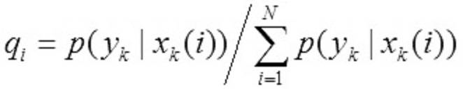
更新部15は、算出した重みqiによって、パーティクルのリサンプリングを行い、状態変数の確率分布を更新する(S34)。更新部15は、測定値ykを得た後における時間ステップkにおける状態変数の確率分布p(xk|y1:k)を、p(xk|y1:k)=Σk=1
Nqiδ(xk-xk(i))/Nによって近似的に求める。
推定部17は、状態変数の確率分布p(xk|y1:k)に基づいて、路面プロファイルを推定する(S35)。推定部17は、状態変数に含まれる路面の凹凸を表す変数の期待値を求めて、路面プロファイルを推定してよい。
本実施形態に係る路面プロファイル推定装置10によれば、非線形変換と非ガウシアンノイズを含むシミュレーションモデルM1によって状態変数の時間発展を表し、非線形変換と非ガウシアンノイズを含む観測モデルM2によって観測を表すことで、非線形の挙動や非ガウシアンの揺動を正確に記述することができ、路面プロファイルをより精度良く推定することができる。
以上説明した実施形態は、本発明の理解を容易にするためのものであり、本発明を限定して解釈するためのものではない。実施形態が備える各要素並びにその配置、材料、条件、形状及びサイズ等は、例示したものに限定されるわけではなく適宜変更することができる。また、異なる実施形態で示した構成同士を部分的に置換し又は組み合わせることが可能である。
Claims (9)
- 車両が接地する路面に対して垂直方向の加速度及びピッチ軸に関する角速度を取得する取得部と、
前記加速度を積分して前記垂直方向の変位を算出し、前記角速度を積分して前記ピッチ軸に関する角度変位を算出する第1算出部と、
シミュレーションモデルに基づいて、前記車両が走行する路面の凹凸を表す変数、前記車両の上下運動を表す変数及び前記車両のピッチ軸に関する回転運動を表す変数を含む状態変数の時間発展を予測する予測部と、
観測モデルに基づいて、前記予測部により予測された前記状態変数から、前記加速度、前記角速度、前記変位及び前記角度変位を算出する第2算出部と、
前記取得部により取得された前記加速度及び前記角速度並びに前記第1算出部により算出された前記変位及び前記角度変位と、前記第2算出部により算出された前記加速度、前記角速度、前記変位及び前記角度変位とのデータ同化によって、前記状態変数を更新する更新部と、
前記状態変数に含まれる前記路面の凹凸を表す変数に基づいて、前記路面のプロファイルを推定する推定部と、
を備える路面プロファイル推定装置。 - 前記予測部により予測される時点よりも後に前記取得部により取得された前記加速度及び前記角速度並びに前記第1算出部により算出された前記変位及び前記角度変位に基づいて、前記状態変数を平滑化する平滑部をさらに備える、
請求項1に記載の路面プロファイル推定装置。 - 前記シミュレーションモデルは、前記車両のハーフカーモデルであり、
前記状態変数は、前記ハーフカーモデルの状態を表す変数である、
請求項1又は2に記載の路面プロファイル推定装置。 - 前記路面の凹凸を表す変数は、前記ハーフカーモデルのフロントタイヤの垂直方向の変位及び速度と、前記ハーフカーモデルのリアタイヤの垂直方向の変位及び速度とを含み、
前記車両の上下運動を表す変数は、前記ハーフカーモデルの重心の垂直方向の変位及び速度と、前記ハーフカーモデルのフロントサスペンションの垂直方向の変位及び速度と、前記ハーフカーモデルのリアサスペンションの垂直方向の変位及び速度とを含み、
前記車両のピッチ軸に関する回転運動を表す変数は、前記ハーフカーモデルの重心を通るピッチ軸に関する回転角及び角速度を含む、
請求項3に記載の路面プロファイル推定装置。 - 前記シミュレーションモデルは、前記状態変数の線形変換又は非線形変換とガウシアンノイズ又は非ガウシアンノイズによって前記状態変数の時間発展を表すモデルであり、
前記観測モデルは、前記状態変数の線形変換又は非線形変換とガウシアンノイズ又は非ガウシアンノイズによって、前記加速度、前記角速度、前記変位及び前記角度変位を算出するモデルである、
請求項1から4のいずれか1項に記載の路面プロファイル推定装置。 - 前記シミュレーションモデルは、前記状態変数の線形変換とガウシアンノイズによって前記状態変数の時間発展を表すモデルであり、
前記観測モデルは、前記状態変数の線形変換とガウシアンノイズによって、前記加速度、前記角速度、前記変位及び前記角度変位を算出するモデルであり、
前記更新部は、前記状態変数の2乗誤差を最小化するように、前記状態変数を更新する、
請求項5に記載の路面プロファイル推定装置。 - 車両に設置され、前記車両が接地する路面に対して垂直方向の加速度を測定する加速度計と、
前記車両に設置され、前記車両のピッチ軸に関する角速度を測定する角速度計と、
前記車両が走行する路面のプロファイルを推定する路面プロファイル推定装置と、を含み、
前記路面プロファイル推定装置は、
前記加速度計から前記加速度を取得し、前記角速度計から前記角速度を取得する取得部と、
前記加速度を積分して前記垂直方向の変位を算出し、前記角速度を積分して前記ピッチ軸に関する角度変位を算出する第1算出部と、
シミュレーションモデルに基づいて、前記車両が走行する路面の凹凸を表す変数、前記車両の上下運動を表す変数及び前記車両のピッチ軸に関する回転運動を表す変数を含む状態変数の時間発展を予測する予測部と、
観測モデルに基づいて、前記予測部により予測された前記状態変数から、前記加速度、前記角速度、前記変位及び前記角度変位を算出する第2算出部と、
前記取得部により取得された前記加速度及び前記角速度並びに前記第1算出部により算出された前記変位及び前記角度変位と、前記第2算出部により算出された前記加速度、前記角速度、前記変位及び前記角度変位とのデータ同化によって、前記状態変数を更新する更新部と、
前記状態変数に含まれる前記路面の凹凸を表す変数に基づいて、前記路面のプロファイルを推定する推定部と、
を備える、
路面プロファイル推定システム。 - 車両が接地する路面に対して垂直方向の加速度及びピッチ軸に関する角速度を取得する第1ステップと、
前記加速度を積分して前記垂直方向の変位を算出し、前記角速度を積分して前記ピッチ軸に関する角度変位を算出する第2ステップと、
シミュレーションモデルに基づいて、前記車両が走行する路面の凹凸を表す変数、前記車両の上下運動を表す変数及び前記車両のピッチ軸に関する回転運動を表す変数を含む状態変数の時間発展を予測する第3ステップと、
観測モデルに基づいて、前記第3ステップにおいて予測された前記状態変数から、前記加速度、前記角速度、前記変位及び前記角度変位を算出する第4ステップと、
前記第1ステップにおいて取得された前記加速度及び前記角速度並びに前記第2ステップにおいて算出された前記変位及び前記角度変位と、前記第4ステップにおいて算出された前記加速度、前記角速度、前記変位及び前記角度変位とのデータ同化によって、前記状態変数を更新する第5ステップと、
前記状態変数に含まれる前記路面の凹凸を表す変数に基づいて、前記路面のプロファイルを推定する第6ステップと、
を含む路面プロファイル推定方法。 - 路面プロファイル推定装置に備えられたコンピュータを、
車両が接地する路面に対して垂直方向の加速度及びピッチ軸に関する角速度を取得する取得部、
前記加速度を積分して前記垂直方向の変位を算出し、前記角速度を積分して前記ピッチ軸に関する角度変位を算出する第1算出部、
シミュレーションモデルに基づいて、前記車両が走行する路面の凹凸を表す変数、前記車両の上下運動を表す変数及び前記車両のピッチ軸に関する回転運動を表す変数を含む状態変数の時間発展を予測する予測部、
観測モデルに基づいて、前記予測部により予測された前記状態変数から、前記加速度、前記角速度、前記変位及び前記角度変位を算出する第2算出部、
前記取得部により取得された前記加速度及び前記角速度並びに前記第1算出部により算出された前記変位及び前記角度変位と、前記第2算出部により算出された前記加速度、前記角速度、前記変位及び前記角度変位とのデータ同化によって、前記状態変数を更新する更新部、及び
前記状態変数に含まれる前記路面の凹凸を表す変数に基づいて、前記路面のプロファイルを推定する推定部、
として機能させる路面プロファイル推定プログラム。
Priority Applications (4)
| Application Number | Priority Date | Filing Date | Title |
|---|---|---|---|
| ES18791073T ES2921304T3 (es) | 2017-04-27 | 2018-04-27 | Dispositivo de estimación del perfil de la superficie de la carretera, sistema de estimación del perfil de la superficie de la carretera, procedimiento de estimación del perfil de la superficie de la carretera y programa de estimación del perfil de la superficie de la carretera |
| CN201880042950.7A CN110832273A (zh) | 2017-04-27 | 2018-04-27 | 路面纵断面推断装置、路面纵断面推断系统、路面纵断面推断方法及路面纵断面推断程序 |
| EP18791073.2A EP3617647B1 (en) | 2017-04-27 | 2018-04-27 | Road surface profile estimating device, road surface profile estimating system, road surface profile estimating method, and road surface profile estimating program |
| US16/608,669 US20200270824A1 (en) | 2017-04-27 | 2018-04-27 | Road surface profile estimation device, road surface profile estimati0n system, road surface profile estimation method, and road surface profile estimation program |
Applications Claiming Priority (2)
| Application Number | Priority Date | Filing Date | Title |
|---|---|---|---|
| JP2017088700A JP6842112B2 (ja) | 2017-04-27 | 2017-04-27 | 路面プロファイル推定装置、路面プロファイル推定システム、路面プロファイル推定方法及び路面プロファイル推定プログラム |
| JP2017-088700 | 2017-04-27 |
Publications (1)
| Publication Number | Publication Date |
|---|---|
| WO2018199286A1 true WO2018199286A1 (ja) | 2018-11-01 |
Family
ID=63918982
Family Applications (1)
| Application Number | Title | Priority Date | Filing Date |
|---|---|---|---|
| PCT/JP2018/017182 Ceased WO2018199286A1 (ja) | 2017-04-27 | 2018-04-27 | 路面プロファイル推定装置、路面プロファイル推定システム、路面プロファイル推定方法及び路面プロファイル推定プログラム |
Country Status (6)
| Country | Link |
|---|---|
| US (1) | US20200270824A1 (ja) |
| EP (1) | EP3617647B1 (ja) |
| JP (1) | JP6842112B2 (ja) |
| CN (1) | CN110832273A (ja) |
| ES (1) | ES2921304T3 (ja) |
| WO (1) | WO2018199286A1 (ja) |
Cited By (2)
| Publication number | Priority date | Publication date | Assignee | Title |
|---|---|---|---|---|
| WO2020100784A1 (ja) * | 2018-11-13 | 2020-05-22 | 国立大学法人東京大学 | 路面プロファイル推定装置、路面プロファイル推定システム、路面プロファイル推定方法及び路面プロファイル推定プログラム |
| CN113570057A (zh) * | 2021-09-27 | 2021-10-29 | 岚图汽车科技有限公司 | 一种基于模型训练的车辆轮心垂向位移测量方法和装置 |
Families Citing this family (14)
| Publication number | Priority date | Publication date | Assignee | Title |
|---|---|---|---|---|
| JP6810779B1 (ja) * | 2019-09-26 | 2021-01-06 | 株式会社ショーワ | 状態量算出装置、制御装置および車両 |
| US11718304B2 (en) | 2020-03-06 | 2023-08-08 | Deere & Comoanv | Method and system for estimating surface roughness of ground for an off-road vehicle to control an implement |
| US11684005B2 (en) | 2020-03-06 | 2023-06-27 | Deere & Company | Method and system for estimating surface roughness of ground for an off-road vehicle to control an implement |
| US11678599B2 (en) * | 2020-03-12 | 2023-06-20 | Deere & Company | Method and system for estimating surface roughness of ground for an off-road vehicle to control steering |
| US11667171B2 (en) | 2020-03-12 | 2023-06-06 | Deere & Company | Method and system for estimating surface roughness of ground for an off-road vehicle to control steering |
| US11685381B2 (en) | 2020-03-13 | 2023-06-27 | Deere & Company | Method and system for estimating surface roughness of ground for an off-road vehicle to control ground speed |
| US11753016B2 (en) | 2020-03-13 | 2023-09-12 | Deere & Company | Method and system for estimating surface roughness of ground for an off-road vehicle to control ground speed |
| JP6817483B1 (ja) * | 2020-06-29 | 2021-01-20 | 株式会社ショーワ | 路面荷重推定装置、車両制御装置および路面荷重推定方法 |
| KR102739193B1 (ko) * | 2020-07-30 | 2024-12-06 | 현대자동차주식회사 | 차량 서스펜션 제어 장치 및 방법 |
| KR102764282B1 (ko) * | 2020-07-30 | 2025-02-07 | 현대자동차주식회사 | 차량 서스펜션 제어 장치 및 방법 |
| US20240185646A1 (en) * | 2021-03-30 | 2024-06-06 | Bridgestone Europe NV/SA [BE/BE] | International roughness index estimation method and system |
| CN113353085B (zh) * | 2021-07-03 | 2023-03-21 | 西北工业大学 | 一种基于卡尔曼滤波理论的路面不平度识别方法 |
| DE102021209136A1 (de) * | 2021-08-19 | 2023-02-23 | Robert Bosch Gesellschaft mit beschränkter Haftung | Verfahren und Vorrichtung zum Ermitteln und Charakterisieren von Fahrbahnunebenheiten |
| JP7618145B2 (ja) | 2023-05-16 | 2025-01-21 | 国立大学法人 東京大学 | 路面3次元形状推定装置、路面3次元形状の推定方法、路面3次元形状推定システム、及び路面3次元形状推定プログラム |
Citations (3)
| Publication number | Priority date | Publication date | Assignee | Title |
|---|---|---|---|---|
| US20120197588A1 (en) * | 2011-01-27 | 2012-08-02 | Hon Hai Precision Industry Co., Ltd. | Apparatus and method for inspecting road surfaces |
| JP2014077257A (ja) * | 2012-10-10 | 2014-05-01 | Koichi Yagi | 路面性状計測装置 |
| JP2017040486A (ja) | 2015-08-17 | 2017-02-23 | 国立大学法人 東京大学 | 自転車の振動応答を利用した路面プロファイル測定装置並びに測定方法 |
Family Cites Families (1)
| Publication number | Priority date | Publication date | Assignee | Title |
|---|---|---|---|---|
| JP3074464B2 (ja) * | 1996-12-05 | 2000-08-07 | 株式会社パスコ | 道路縦断プロファイル測定装置 |
-
2017
- 2017-04-27 JP JP2017088700A patent/JP6842112B2/ja active Active
-
2018
- 2018-04-27 ES ES18791073T patent/ES2921304T3/es active Active
- 2018-04-27 US US16/608,669 patent/US20200270824A1/en not_active Abandoned
- 2018-04-27 EP EP18791073.2A patent/EP3617647B1/en active Active
- 2018-04-27 CN CN201880042950.7A patent/CN110832273A/zh active Pending
- 2018-04-27 WO PCT/JP2018/017182 patent/WO2018199286A1/ja not_active Ceased
Patent Citations (3)
| Publication number | Priority date | Publication date | Assignee | Title |
|---|---|---|---|---|
| US20120197588A1 (en) * | 2011-01-27 | 2012-08-02 | Hon Hai Precision Industry Co., Ltd. | Apparatus and method for inspecting road surfaces |
| JP2014077257A (ja) * | 2012-10-10 | 2014-05-01 | Koichi Yagi | 路面性状計測装置 |
| JP2017040486A (ja) | 2015-08-17 | 2017-02-23 | 国立大学法人 東京大学 | 自転車の振動応答を利用した路面プロファイル測定装置並びに測定方法 |
Non-Patent Citations (3)
| Title |
|---|
| DOUANGPHACHANH, VIENGNAM ET AL.: "Exploring the Use of Smartphone Accelerometer and Gyroscope to Study on the Estimation of Road Surface Roughness Condition", 2014 11TH INTERNATIONAL CONFERENCE ON INFORMATICS IN CONTROL, AUTOMATION AND ROBOTICS, 26 February 2015 (2015-02-26), pages 783 - 787, XP032740344 * |
| JEONG, WEUIBONG ET AL.: "State estimation of a road surface and vehicle system using a Kalman filter", TRANSACTIONS OF THE JAPAN SOCIETY OF MECHANICAL ENGINEERS, vol. 55, no. 515, 1989, pages 1672 - 1679, XP055528307 * |
| See also references of EP3617647A4 |
Cited By (7)
| Publication number | Priority date | Publication date | Assignee | Title |
|---|---|---|---|---|
| WO2020100784A1 (ja) * | 2018-11-13 | 2020-05-22 | 国立大学法人東京大学 | 路面プロファイル推定装置、路面プロファイル推定システム、路面プロファイル推定方法及び路面プロファイル推定プログラム |
| CN112997225A (zh) * | 2018-11-13 | 2021-06-18 | 国立大学法人东京大学 | 路面纵断面推断装置、路面纵断面推断系统、路面纵断面推断方法以及路面纵断面推断程序 |
| JPWO2020100784A1 (ja) * | 2018-11-13 | 2021-09-30 | 国立大学法人 東京大学 | 路面プロファイル推定装置、路面プロファイル推定システム、路面プロファイル推定方法及び路面プロファイル推定プログラム |
| EP3882880A4 (en) * | 2018-11-13 | 2022-08-24 | The University of Tokyo | ROAD SURFACE PROFILE ESTIMATION DEVICE, ROAD SURFACE PROFILE ESTIMATION SYSTEM, ROAD SURFACE PROFILE ESTIMATION METHOD AND ROAD SURFACE PROFILE ESTIMATION PROGRAM |
| CN112997225B (zh) * | 2018-11-13 | 2023-02-03 | 国立大学法人东京大学 | 路面纵断面推断装置、路面纵断面推断系统、路面纵断面推断方法以及存储介质 |
| JP7390731B2 (ja) | 2018-11-13 | 2023-12-04 | 国立大学法人 東京大学 | 路面プロファイル推定装置、路面プロファイル推定システム、路面プロファイル推定方法及び路面プロファイル推定プログラム |
| CN113570057A (zh) * | 2021-09-27 | 2021-10-29 | 岚图汽车科技有限公司 | 一种基于模型训练的车辆轮心垂向位移测量方法和装置 |
Also Published As
| Publication number | Publication date |
|---|---|
| EP3617647B1 (en) | 2022-06-15 |
| JP6842112B2 (ja) | 2021-03-17 |
| EP3617647A1 (en) | 2020-03-04 |
| EP3617647A4 (en) | 2021-01-27 |
| US20200270824A1 (en) | 2020-08-27 |
| CN110832273A (zh) | 2020-02-21 |
| JP2018185276A (ja) | 2018-11-22 |
| ES2921304T3 (es) | 2022-08-23 |
Similar Documents
| Publication | Publication Date | Title |
|---|---|---|
| WO2018199286A1 (ja) | 路面プロファイル推定装置、路面プロファイル推定システム、路面プロファイル推定方法及び路面プロファイル推定プログラム | |
| CN112660112B (zh) | 一种车辆侧倾状态及侧翻预测方法及系统 | |
| JP7265912B2 (ja) | 演算モデル生成システム、摩耗量推定システムおよび演算モデル生成方法 | |
| CN109154498B (zh) | 道路监测方法及系统 | |
| CN113353085B (zh) | 一种基于卡尔曼滤波理论的路面不平度识别方法 | |
| JP7578488B2 (ja) | 摩耗量推定システム、演算モデル生成システムおよび摩耗量推定方法 | |
| EP3882880B1 (en) | Road surface profile estimating device, road surface profile estimating system, road surface profile estimating method, and road surface profile estimating program | |
| CN117309429B (zh) | 智能网联汽车的淋雨试验检测平台 | |
| JP2017223640A (ja) | 舗装面ひび割れ検査方法 | |
| CN117261874A (zh) | 一种基于自适应无迹卡尔曼滤波的车辆侧翻风险预警方法 | |
| CN114516251B (zh) | 一种车辆动力学参数辨识方法、系统、车辆及存储介质 | |
| CN109849932A (zh) | 一种路面自适应的车轮动载荷估计系统及方法 | |
| Stallmann | Tyre model verification over off-road terrain | |
| JP7595494B2 (ja) | 摩耗量推定システム、演算モデル生成システムおよび摩耗量推定方法 | |
| Vazquez et al. | Road profile and suspension state estimation boosted with vehicle dynamics conjectures | |
| CN115563694B (zh) | 一种基于预测时域内误差的车辆动力学模型精度评价方法 | |
| CN110670458B (zh) | 基于行车振动数据的路面车辙检测方法 | |
| Kim et al. | Estimation of lateral tire force from objective measurement data for handling analysis | |
| CN117113726B (zh) | 基于复杂环境模拟的实验室车辆行驶安全测试系统 | |
| KR20260016932A (ko) | 다수의 바퀴를 갖는 차량의 가상 프로토타입 생성 방법 | |
| KR101261324B1 (ko) | 동체의 각속도 측정방법 | |
| HK1260153A1 (en) | Road monitoring method and system | |
| Xu et al. | BASED ON RBF NEURAL NETWORK VEHICLE OPERATING POSTURE FOR RAPID DETECTION OF INTELLIGENT SENSOR CALIBRATION METHOD |
Legal Events
| Date | Code | Title | Description |
|---|---|---|---|
| 121 | Ep: the epo has been informed by wipo that ep was designated in this application |
Ref document number: 18791073 Country of ref document: EP Kind code of ref document: A1 |
|
| NENP | Non-entry into the national phase |
Ref country code: DE |
|
| ENP | Entry into the national phase |
Ref document number: 2018791073 Country of ref document: EP Effective date: 20191127 |