WO2018207282A1 - 対象物認識方法、装置、システム、プログラム - Google Patents
対象物認識方法、装置、システム、プログラム Download PDFInfo
- Publication number
- WO2018207282A1 WO2018207282A1 PCT/JP2017/017695 JP2017017695W WO2018207282A1 WO 2018207282 A1 WO2018207282 A1 WO 2018207282A1 JP 2017017695 W JP2017017695 W JP 2017017695W WO 2018207282 A1 WO2018207282 A1 WO 2018207282A1
- Authority
- WO
- WIPO (PCT)
- Prior art keywords
- parameter
- time point
- parts
- cloud data
- unit
- Prior art date
- Legal status (The legal status is an assumption and is not a legal conclusion. Google has not performed a legal analysis and makes no representation as to the accuracy of the status listed.)
- Ceased
Links
Images






Classifications
-
- G—PHYSICS
- G06—COMPUTING OR CALCULATING; COUNTING
- G06V—IMAGE OR VIDEO RECOGNITION OR UNDERSTANDING
- G06V40/00—Recognition of biometric, human-related or animal-related patterns in image or video data
- G06V40/20—Movements or behaviour, e.g. gesture recognition
- G06V40/23—Recognition of whole body movements, e.g. for sport training
-
- G—PHYSICS
- G06—COMPUTING OR CALCULATING; COUNTING
- G06T—IMAGE DATA PROCESSING OR GENERATION, IN GENERAL
- G06T7/00—Image analysis
- G06T7/70—Determining position or orientation of objects or cameras
- G06T7/77—Determining position or orientation of objects or cameras using statistical methods
-
- G—PHYSICS
- G06—COMPUTING OR CALCULATING; COUNTING
- G06T—IMAGE DATA PROCESSING OR GENERATION, IN GENERAL
- G06T7/00—Image analysis
- G06T7/20—Analysis of motion
-
- G—PHYSICS
- G06—COMPUTING OR CALCULATING; COUNTING
- G06V—IMAGE OR VIDEO RECOGNITION OR UNDERSTANDING
- G06V20/00—Scenes; Scene-specific elements
- G06V20/40—Scenes; Scene-specific elements in video content
- G06V20/41—Higher-level, semantic clustering, classification or understanding of video scenes, e.g. detection, labelling or Markovian modelling of sport events or news items
-
- G—PHYSICS
- G06—COMPUTING OR CALCULATING; COUNTING
- G06V—IMAGE OR VIDEO RECOGNITION OR UNDERSTANDING
- G06V40/00—Recognition of biometric, human-related or animal-related patterns in image or video data
- G06V40/10—Human or animal bodies, e.g. vehicle occupants or pedestrians; Body parts, e.g. hands
- G06V40/103—Static body considered as a whole, e.g. static pedestrian or occupant recognition
-
- G—PHYSICS
- G06—COMPUTING OR CALCULATING; COUNTING
- G06T—IMAGE DATA PROCESSING OR GENERATION, IN GENERAL
- G06T2207/00—Indexing scheme for image analysis or image enhancement
- G06T2207/10—Image acquisition modality
- G06T2207/10028—Range image; Depth image; 3D point clouds
-
- G—PHYSICS
- G06—COMPUTING OR CALCULATING; COUNTING
- G06T—IMAGE DATA PROCESSING OR GENERATION, IN GENERAL
- G06T2207/00—Indexing scheme for image analysis or image enhancement
- G06T2207/30—Subject of image; Context of image processing
- G06T2207/30196—Human being; Person
Definitions
- the present disclosure relates to an object recognition method, an object recognition apparatus, an object recognition system, and an object recognition program.
- a technique for tracking the skeleton of an object based on point cloud data scattered on the surface of the object such as a person is known (for example, see Non-Patent Document 1).
- This technique assumes a mixed Gaussian distribution for the distribution of point cloud data and assumes that the center (feature point) of each Gaussian distribution is fixed to the surface of the object.
- the skeleton of the object is tracked by tracking the feature points.
- an object of the present invention is to accurately recognize a joint or skeleton of an object with a relatively low calculation load.
- point cloud data relating to the surface of an object having a plurality of joints is acquired, A first parameter representing a position and an axial direction of each of a plurality of parts of the object, wherein the first parameter at a first time point is derived or obtained; The first parameter at the second time point based on the point cloud data at the second time point after the first time point, the first parameter at the first time point, and the geometric model having an axis.
- a computer-implemented object recognition method is provided that includes deriving.
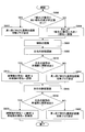
- FIG. 10 is a schematic flowchart for explaining a determination method by a full width at half maximum by a length calculation unit 128; 3 is a schematic flowchart showing an example of the overall operation of the object recognition system 1. It is a schematic flowchart which shows an example of a site
- FIG. 1 is a diagram schematically showing a schematic configuration of an object recognition system 1 according to an embodiment.
- FIG. 1 shows a target person S (an example of an object) for explanation.
- the distance image sensor 21 acquires a distance image of the subject S.
- the distance image sensor 21 is a three-dimensional image sensor, measures the distance by sensing the entire space, and acquires a distance image (an example of point cloud data) having distance information for each pixel like a digital image.
- the acquisition method of distance information is arbitrary.
- the distance information acquisition method may be an active stereo method in which a specific pattern is projected onto an object, read by an image sensor, and the distance is acquired by a triangulation method from the geometric distortion of the projection pattern.
- a TOF (Time-of-Flight) method may be used in which laser light is irradiated, reflected light is read by an image sensor, and a distance is measured from the phase shift.
- the distance image sensor 21 may be installed in a manner in which the position is fixed, or may be installed in a manner in which the position is movable.
- the object recognition device 100 recognizes the joint and skeleton of the subject S based on the distance image obtained from the distance image sensor 21. This recognition method will be described in detail later.
- the target person S is a person or a humanoid robot, and has a plurality of joints. In the following, it is assumed that the target person S is a person as an example.
- the target person S may be a specific individual or an unspecified person depending on the application. For example, when the use is an analysis of a movement during a competition such as gymnastics, the target person S may be an athlete.
- the distance image sensor 21 is preferably a target as shown schematically in FIG. A plurality of points are installed so that point cloud data close to the three-dimensional shape of the person S can be obtained.
- the wireless communication path is based on short-range wireless communication, Bluetooth (registered trademark), Wi-Fi (Wireless Fidelity), or the like. It may be realized. Further, the object recognition device 100 may be realized in cooperation with two or more different devices (for example, a computer and a server).
- FIG. 2 is a diagram illustrating an example of a hardware configuration of the object recognition apparatus 100.
- the object recognition apparatus 100 includes a control unit 101, a main storage unit 102, an auxiliary storage unit 103, a drive device 104, a network I / F unit 106, and an input unit 107.
- the control unit 101 is an arithmetic device that executes a program stored in the main storage unit 102 or the auxiliary storage unit 103, receives data from the input unit 107 or the storage device, calculates, processes, and outputs the data to the storage device or the like. To do.
- the control unit 101 may include, for example, a CPU (Central Processing Unit) and a GPU.
- the main storage unit 102 is a ROM (Read Only Memory), a RAM (Random Access Memory), or the like, and a storage device that stores or temporarily stores programs and data such as an OS and application software that are basic software executed by the control unit 101 It is.
- ROM Read Only Memory
- RAM Random Access Memory
- the auxiliary storage unit 103 is an HDD (Hard Disk Drive) or the like, and is a storage device that stores data related to application software.
- HDD Hard Disk Drive
- the drive device 104 reads the program from the recording medium 105, for example, a flexible disk, and installs it in the storage device.
- the recording medium 105 stores a predetermined program.
- the program stored in the recording medium 105 is installed in the object recognition device 100 via the drive device 104.
- the installed predetermined program can be executed by the object recognition apparatus 100.
- the network I / F unit 106 is an interface between the target object recognition apparatus 100 and a peripheral device having a communication function connected via a network constructed by a data transmission path such as a wired and / or wireless line.
- the input unit 107 includes a keyboard having cursor keys, numeric input, various function keys, and the like, a mouse, a slice pad, and the like.
- the input unit 107 may correspond to other input methods such as voice input and gestures.
- various processes described below can be realized by causing the object recognition apparatus 100 to execute a program. It is also possible to record the program on the recording medium 105 and cause the object recognition apparatus 100 to read the recording medium 105 on which the program is recorded, thereby realizing various processes described below.
- various types of recording media can be used as the recording medium 105.
- a recording medium that records information optically, electrically, or magnetically such as a CD-ROM, a flexible disk, or a magneto-optical disk, or a semiconductor memory that electrically records information, such as a ROM or flash memory It may be.
- the recording medium 105 does not include a carrier wave.
- the object recognition apparatus 100 includes a data input unit 110 (an example of an acquisition unit), a one-scene skeleton recognition unit 120 (an example of a parameter derivation / acquisition unit), and a geometric model database 140 (in FIG. 3, “geometric model DB”). And notation).
- the object recognition apparatus 100 includes a calibration information storage unit 142, a minute fitting processing unit 150 (an example of a derivation processing unit), and an output unit 160.
- the data input unit 110, the 1 scene skeleton recognition unit 120, the micro fitting processing unit 150, and the output unit 160 are executed by the control unit 101 illustrated in FIG. 2 executing one or more programs stored in the main storage unit 102. realizable.
- the geometric model database 140 may be realized by the auxiliary storage unit 103 illustrated in FIG.
- the calibration information storage unit 142 may be realized by the main storage unit 102 (for example, RAM) shown in FIG.
- a part of the function of the object recognition apparatus 100 may be realized by a computer that can be incorporated in the distance image sensor 21
- the distance image (hereinafter referred to as “point cloud data”) is input from the distance image sensor 21 and the joint model to be used is input to the data input unit 110.
- the point cloud data is as described above, and may be input for each frame period, for example.
- the point cloud data may include a set of distance images from the plurality of distance image sensors 21.
- the joint model to be used is an arbitrary model related to the subject S, for example, a model represented by a plurality of joints and a skeleton (link) between the joints.
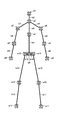
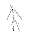
- a joint model as shown in FIG. 4 is used.
- the joint model as shown in FIG. 4 is a 16-joint model having one head, three torso parts (torso parts), both arm parts, and both leg parts. Others are defined as joints at both ends and midpoint. Specifically, it consists of 16 joints a0 to a15 and 15 skeletons b1 to b15 (or also referred to as “parts b1 to b15”) connecting the joints.
- the joints a4 and a7 are left and right shoulder joints, and the joint a2 is a joint related to the cervical spine.
- the joints a4 and a7 are the left and right hip joints, and the joint a0 is a joint related to the lumbar spine.
- the skeletons b14 and b15 related to the hip joint and the skeletons b4 and b7 related to the shoulder joint are skeletons (hereinafter referred to as “hidden skeletons”) that cannot be accurately recognized only by fitting using a geometric model described later. Also called).
- hidden skeletons skeletons
- the one-scene skeleton recognition unit 120 performs a one-scene skeleton recognition process based on the point cloud data of the subject S related to a certain temporary point (one scene).
- the one-scene skeleton recognition process generates calibration information as a fitting result by performing fitting using a geometric model on the point cloud data of the subject S related to a certain temporary point (one scene). Including.
- a fitting method using a geometric model will be described later together with a method for generating calibration information.
- a time point when the calibration information is generated by the one-scene skeleton recognition unit 120 is referred to as a “calibration time point”.
- the calibration execution time point may be the first time point, or may come every predetermined time or when a predetermined condition is satisfied.
- the 1-scene skeleton recognition unit 120 When the 1-scene skeleton recognition unit 120 generates the calibration information, the 1-scene skeleton recognition unit 120 stores the generated calibration information in the calibration information storage unit 142.
- the processing in the one-scene skeleton recognition unit 120 has a significantly higher processing load than the processing in the minute fitting processing unit 150 described later. Therefore, although depending on the processing capability of the object recognition apparatus 100, the generation of calibration information may take a longer time than the frame period. In this case, measures such as allowing the subject person S to stand still may be taken until the processing by the minute fitting processing unit 150 can be started (that is, until the generation of calibration information is completed).
- the micro-fitting processing unit 150 performs the subject S based on the point cloud data of the subject S related to a certain temporary point (one scene) after the calibration is performed and the calibration information in the calibration information storage unit 142. Generate skeleton information.
- the minute fitting processing unit 150 generates the skeleton information of the target person S by the minute fitting process using the geometric model. The method of the micro fitting process will be described later.
- the skeletal information may include information that can specify the positions of the joints a0 to a15. Further, the skeleton information may include information that can specify the position, orientation, and thickness of the skeletons b1 to b15. The use of the skeleton information is arbitrary, but may be used to derive the skeleton information in the next frame period.
- the skeletal information may ultimately be used for analysis of the movement of the subject S during competition such as gymnastics.
- technique recognition based on skeletal information may be realized.
- the movement of the target person S assumed to be an operator may be analyzed and used for a robot program.
- it can be used for user interface by gestures, personal identification, quantification of skilled techniques, and the like.
- the output unit 160 outputs the skeleton information of the subject S (denoted as “recognition result” in FIG. 3) to a display device or the like (not shown).
- the output unit 160 may output the skeleton information of the subject S approximately in real time for each frame period.
- the output unit 160 outputs the skeleton information of the subject S based on the calibration information at the time of calibration execution, and the skeleton information of the subject S from the minute fitting processing unit 150 at the time of non-calibration. It may be output.
- the output unit 160 may output the skeleton information in time series in non-real time for the purpose of explaining the movement of the subject S.
- the minute fitting processing unit 150 performs the minute fitting process based on the fitting result (calibration information) using the geometric model by the one-scene skeleton recognition unit 120, so that the target The skeleton information of the person S can be generated.
- the computational load is reduced as compared with the case where the fitting using the geometric model by the one-scene skeleton recognition unit 120 is performed for each frame, so that the joint or skeleton of the object can be accurately recognized with a relatively low computational load. it can. This makes it applicable to high-speed and complicated motion analysis such as gymnastics and figure skating.
- the one-scene skeleton recognition unit 120 includes a clustering unit 122, an EM algorithm unit 124, a model optimization unit 126, and a length calculation unit 128.
- the object recognition apparatus 100 further includes a part recognition unit 130, a skeleton shaping unit 132, and a calibration information generation unit 134.
- the clustering unit 122 clusters the point cloud data input to the data input unit 110, performs fitting for each cluster, and obtains an initial fitting result (initial value used for fitting using a geometric model described later).
- Kmeans ++ method or the like can be used as a clustering method.
- the number of clusters given to the clustering unit 122 may be manually input, or a predetermined number corresponding to the skeleton model may be used.
- the predetermined number corresponding to the skeleton model is, for example, a value obtained by subtracting the number of parts related to the hidden skeleton from the total number of parts related to the skeleton model. That is, in the case of the 16 joint (15 sites) model shown in FIG.
- the predetermined number that is the initial number of clusters is “11”.
- a part of the model is rejected according to the fitting result by clustering.
- a rejection method a method may be used in which a threshold is set for the data sum of the posterior distribution, which is an expected value of the number of point cloud data that can be explained by the model, and the model below the threshold is rejected.
- the clustering unit 122 can obtain an initial value used for fitting using a geometric model described later by performing fitting again with the number of clusters.
- an initial value used for fitting may be acquired by the machine learning unit.
- the machine learning unit performs label division (part recognition) on 15 parts based on the point cloud data input to the data input part 110.
- a random forest may be used as the machine learning method, and the difference between the distance values of the target pixel and the surrounding pixels may be used as the feature amount.
- a method of performing multi-class classification of each pixel using a distance image as an input may be used.
- feature quantities other than the difference in distance value may be used, or deep learning (Deep Learning) in which learning is performed including parameters corresponding to the feature quantities may be used.
- the EM algorithm unit 124 determines the parameter ⁇ so that the point cloud data x n is most concentrated on the surface of the geometric model.
- the point group data x n is a set (x 1 , x 2 ,..., X N ) of N points (for example, position vectors) expressed by three-dimensional spatial coordinates (x, y, z). is there.
- the x component and y component of the spatial coordinates are values of two-dimensional coordinates in the image plane
- the x component is a horizontal component
- the y component is a vertical component.
- the z component represents a distance.
- r m and ⁇ 2 are scalars, and c m 0 and e m 0 are vectors.
- e m 0 is a unit vector. That is, e m 0 is a unit vector representing the direction of the axis of the cylinder.
- the position c m 0 is a position vector related to the position of an arbitrary point on the axis of the cylinder.
- the length (height) in the axial direction of the cylinder is indefinite.
- the orientation e m 0 of the geometric model is the same concept as the axial direction of the geometric model.
- p (x n ) is a mixed probability distribution model of the point cloud data x n , as described above, ⁇ 2 is a variance, and M ′ is the number of clusters obtained by the clustering unit 122. It is done. At this time, the corresponding log likelihood function is as follows.
- N is the number of data (the number of data included in the point cloud data related to one frame).
- Equation 2 is a log-likelihood function of a mixed Gaussian model
- an EM algorithm or the like can be used.
- the EM algorithm unit 124 derives a parameter ⁇ and a variance ⁇ 2 that maximize the log likelihood function based on the EM algorithm.
- the surface residual ⁇ m (x n , ⁇ ) is expressed such that the exponent part in Equation 2 is a square difference. Specifically, It is as follows.
- the EM algorithm is an iteration of an E step for calculating an expected value and an M step for maximizing the expected value.
- the EM algorithm unit 124 calculates the following posterior distribution p nm .
- the EM algorithm unit 124 derives a parameter ⁇ and a variance ⁇ 2 that maximize the following expected value Q ( ⁇ , ⁇ 2 ).
- the posterior distribution p nm is treated as a constant.
- P is the sum of all parts of the data sum of the posterior distribution p nm (hereinafter, also referred to as “the sum of all parts of the data sum of the posterior distribution p nm ”), and is as follows.
- the expected value Q ( ⁇ , ⁇ 2) estimate of the variance sigma 2 to maximize the sigma 2 * is as follows.
- the estimated value r * m of the thickness r m can be directly minimized as follows.
- Equation 9 is an average operation using the posterior distribution p nm , and is as follows for an arbitrary tensor or matrix A nm .
- ⁇ x n > p has dependency on the part m and corresponds to the center of gravity (center) of the geometric model (cylinder) related to the part m.
- the variance-covariance matrix ⁇ xx is also specific to the part m and corresponds to the direction of the geometric model (cylinder) related to the part m.
- the direction e m 0 may be derived by linear approximation. Good.
- the update formula based on the minute rotation is defined in such a manner that the norm is preserved, and is as follows.
- ⁇ e is a minute rotation vector.
- the estimated value ⁇ e * of ⁇ e is obtained by differentiating the equation of Formula 8 by ⁇ e, and is as follows.
- the inverse matrix of the covariance matrix ⁇ yy and the vector ⁇ y2y (subscript “y 2 y”) are as follows.
- the EM algorithm unit 124 first obtains the estimated value c * m 0 of the position c m 0 and then obtains the estimated value r * m of the thickness r m .
- the thickness r m of the parameters ⁇ may be manually entered by the user, the shape information It may be set automatically based on this.
- the EM algorithm unit 124 derives the remaining elements (position c m 0 and direction e m 0 ) of the parameter ⁇ .
- the other measurement may be a precise measurement in advance or may be executed in parallel.
- the model optimizing unit 126 has the best fit at the time of fitting among the plurality of types executed.
- a geometric model of is derived.
- the plurality of types of geometric models include geometric models other than cylinders, which are at least one of a cone, a trapezoidal column, an elliptical column, an elliptical cone, and a trapezoidal elliptical column.
- the multiple types of geometric models related to one part may not include a cylinder.
- the plurality of types of geometric models related to one part may be different for each part.
- a single fixed geometric model may be used without using a plurality of types of geometric models.
- the EM algorithm unit 124 first fits each part using a cylindrical geometric model. Next, the EM algorithm unit 124 switches a geometric model related to a certain part from a cylinder to another (for example, a cone), and performs fitting to the same part. Then, the model optimizing unit 126 selects the geometric model having the largest logarithmic likelihood function as the type of geometric model having the best fit. The model optimizing unit 126 may select the geometric model having the largest sum of all the parts of the posterior distribution data sum as the geometric model having the best fit, instead of the geometric model having the largest log likelihood function. Good.
- the surface residual ⁇ m (x n , ⁇ ) may be expressed as:
- the position c m 0 corresponds to the vertex position
- the direction e m 0 is a unit vector of the central axis.
- the vector nm is a normal vector at a certain point on the surface of the cone.
- the surface residual ⁇ m (x n , ⁇ ) may be the same as in the case of a cone. That is, in the case of a trapezoidal column, it can be expressed by defining a distribution with respect to a part of a cone.
- the surface residual ⁇ m (x n , ⁇ ) may be expressed as follows.
- d m is the focal length
- a m is the length of the major axis of the cross-section of an ellipse
- n m ' is the unit vector in the long axis direction.
- the position c m 0 corresponds to the position on the axis
- the direction e m 0 is a unit vector of the axis of the elliptic cylinder (axial direction).
- the surface residual ⁇ m (x n , ⁇ ) may be expressed as follows.
- ⁇ m1 and ⁇ m2 are inclination angles in the major axis and minor axis directions, respectively.
- the position c m 0 corresponds to the vertex position, and the direction e m 0 is a unit vector of the central axis.
- the surface residual ⁇ m (x n , ⁇ ) may be the same as in the case of the elliptical cone.
- the EM algorithm unit 124 preferably performs a finite length process.
- the finite length process is a process of calculating the posterior distribution p nm only for data satisfying a predetermined condition among the point cloud data x n and setting the posterior distribution p nm to 0 for other data.
- the finite length process is a process for preventing data irrelevant to the part m from being mixed, and the predetermined condition is set so that data irrelevant to the part m can be excluded. Thereby, it can suppress that the point cloud data which should not be actually related influences analysis.
- the data satisfying the predetermined condition may be data satisfying the following expression, for example.
- l m 0 is an input length related to the part m
- ⁇ is a margin (for example, 1.2).
- the input length l m 0 can be manually input, or may be set based on the shape information of the subject S obtained by other measurement.
- the length calculation unit 128 calculates the length (part) from the center to the end of the geometric model.
- the length parameter l m corresponding to (the length from the center of m to the end) is derived.
- the length calculation unit 128 may calculate the length parameter l m of the part m using the variance-covariance matrix ⁇ xx as follows.
- C is a constant multiple correction value.
- the length calculation section 128, the length parameter l m site m may be calculated by determination by the full width at half maximum.
- the full width at half maximum refers to the interval up to where the number of data is halved compared to where there is a lot of data.
- the length calculation unit 128 derives a length parameter by finding the “cut” of the part m.
- the length calculation unit 128 finely cuts the part m along the axial direction in the form of a ring whose normal is the axial direction related to the direction e m 0 , and counts the number of data contained therein.
- a point where the value is equal to or less than a predetermined threshold is defined as a “break”. Specifically, in the determination based on the full width at half maximum, the predetermined threshold is half the maximum value of the count value, but may be a value other than half, such as 0.1 times the maximum value of the count value.
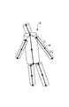
- FIG. 5 is a diagram schematically showing a derivation result (fitting result by a geometric model) by the EM algorithm unit 124
- FIG. 6 is a schematic flowchart for explaining a determination method by the full width at half maximum by the length calculation unit 128. .
- the head and the torso are each fitted with a single cylinder, and both the arms and the legs are fitted with a single cylinder.
- a method for calculating the length parameter l m (l + m and l ⁇ m ) of the part m will be described as a representative case where the arm portion of the subject S is the part m.
- the arm is recognized as one part by the EM algorithm part 124 because the elbow joint is extended (it is applied by one geometric model). .
- step S602 the length calculation unit 128 counts the number of data satisfying the following condition among the point cloud data xn .
- ⁇ X n ⁇ e m 0 > p corresponds to the center of the part m.
- ⁇ l m corresponds to the width of the ring cut (width along the axial direction e m 0 ), and is, for example, 0.01 l m 0 .
- l m 0 is the input length related to the part m as described above.
- S m is a threshold for the posterior distribution p nm , and is 0.1, for example.
- step S604 the length calculation unit 128 sets the reference value Cref based on the count number obtained in step S602. For example, the length calculation unit 128 sets the count obtained in step S602 as the reference value Cref.
- step S606 n is incremented by “1”.
- step S608 the length calculation unit 128 counts the number of data satisfying the following condition in the point cloud data xn . That is, the length calculator 128 in the next section shifted by .DELTA.l m, counts the number of the following conditions data.
- step S610 the length calculation unit 128 determines whether or not the number of data counted in step S608 is equal to or less than a predetermined number times (for example, 0.5 times) the reference value Cref. If the determination result is “YES”, the process proceeds to step S612, and otherwise, the process from step S606 is repeated.
- a predetermined number times for example, 0.5 times
- step S620 to step S632 the length calculation unit 128 proceeds in the reverse direction (ancestor side), and in the same way, from the center to the ancestor side end of the part m shown in FIG.
- the length parameter l - m of is calculated.
- the length calculation unit 128, as follows, may be calculated length parameter l m site m.
- N m is a subset of n defined below, and is a set of n whose posterior distribution p nm is smaller than a certain threshold value p m th .
- the threshold value p m th is, for example, as follows.
- the subset N m is a set of data that does not belong to the part m in the point cloud data x n . Therefore, the length calculation section 128, among the subsets N m, the distance from the center (number 29
- ) to data is minimized Based on this, the length parameter lm of the part m is calculated.
- Region recognition unit 130 a derivation result of the parameters of site m (r m, c m 0 , and e m 0), on the basis of the derivation result of the length parameter l m site m, performs a part recognition process.
- the part recognition process includes recognizing the correspondence between the part m and each part of the subject S (see the parts b1 to b15 in FIG. 4).
- the position of the end of the part m on the axis (the end that determines the length parameter l m ) can be derived.
- the position ⁇ m 0 of the end portion on the axis of the part m satisfies the following.
- Equation 32 the second term on the right side of Equation 32 is as follows at the end on the ancestor side and the end on the descendant side.
- l ⁇ m is the center of the part m Is a length parameter from to the ancestor side, and is calculated by the length calculation unit 128 as described above.
- ⁇ is a constant, and may be 1, for example.
- a “joint point” refers to a representative point related to a joint (a point representing a position related to a joint), and an end (position) of the part m that can be derived in this way also corresponds to the joint point.
- Region recognition unit 130 by using the thickness r m, identifying the main site.
- the main part is the part with the largest thickness, and is the trunk of the subject S in this embodiment.
- the part recognizing unit 130 recognizes the thickest part or two adjacent first and second thickest parts whose thickness difference is less than a predetermined value as the main part of the object. Specifically, when the difference between the first largest part m1 and the second largest part m2 is less than a predetermined value, the part recognition unit 130 determines which part m1, m2 Is also identified as a torso. The predetermined value is a matching value corresponding to the difference in thickness between the parts m1 and m2. On the other hand, when the difference between the first largest part m1 and the second largest part m2 is equal to or greater than a predetermined value, the part recognition unit 130 converts only the first largest part m1 into the trunk (part b1 + part. identified as b2).
- the site recognition unit 130 sets a “cut flag” for the site ml.
- the significance of the disconnect flag will be described later. Accordingly, for example, in FIG. 4, even when the part b1 and the part b2 are straightly extended according to the posture of the subject S, the part b1 and the part b2 can be recognized as the trunks related to the part m1 and the part m2. .
- the part recognizing unit 130 determines (identifies) a joint point in the vicinity of the bottom of the torso after identifying the main part (torso).
- the part recognition unit 130 For the bottom surface of the body part, the part recognition unit 130 has an end part on the body part side in a minute cylinder (or an elliptical column or a trapezoidal column) set at the position of the end part on the bottom surface side of the body part.
- the two parts ml and mr to which the position of belong are specified.
- a predetermined value may be used for the height of the minute cylinder.
- the part recognition unit 130 divides the parts ml and mr into the part related to the left leg (refer to part b10 or part b10 + b11 in FIG. 4) and the part related to the right leg (refer to part b12 or part b12 + b13 in FIG. 4).
- the part recognizing part 130 When the part recognizing part 130 identifies the part ml related to the left leg part, the part recognizing part 130 includes a body part in a sphere (hereinafter also referred to as “connected sphere”) set at the position of the end part far from the body part in the part ml. It is determined whether or not there is a part having an end position on the side close to. A predetermined value may be used for the diameter of the connecting sphere. If there is a part ml2 having the position of the end close to the torso in the connecting sphere, the part recognition unit 130 recognizes the part ml as the thigh b10 of the left leg, and the part ml2 This is recognized as the shin b11 of the left leg.
- the part recognition unit 130 recognizes the part ml as a part including both the thigh and shin of the left leg. To do.
- the site recognition unit 130 sets a “cut flag” for the site ml. Thereby, for example, in FIG. 4, even when the parts b ⁇ b> 10 and b ⁇ b> 11 extend straight according to the posture of the subject S, the parts b ⁇ b> 10 and b ⁇ b> 11 can be recognized as parts related to the left leg.
- the part recognizing unit 130 identifies the part mr related to the right leg part, the part close to the body part in the sphere (connected sphere) set at the position of the end part far from the body part in the part mr. It is determined whether or not there is a part having the position of the end. A predetermined value may be used for the diameter of the connecting sphere.
- the part recognition unit 130 recognizes the part mr as the thigh b12 of the right leg, and the part mr2 This is recognized as the right leg shin b13.
- the part recognition unit 130 recognizes the part mr as a part including both the thigh and shin of the right leg. To do. In this case, the part recognition unit 130 sets a “cut flag” for the part mr. Thereby, for example, in FIG. 4, even when the parts b12 and b13 extend straight according to the posture of the subject S, the parts b12 and b13 can be recognized as parts related to the right leg.
- the part recognition part 130 will determine (identify) the joint point in the side surface vicinity of a trunk
- the site recognizing unit 130 is located on the side surface in the axial direction (principal axis) of the torso, and the two joint points closest to the head side surface are the base joint points of the left and right arms (joint points related to the shoulder joint). Identify as.
- the part recognizing unit 130 identifies a joint point included in a thin torus (a torus related to a cylinder) on the side surface of the trunk as a joint point of the base of the arm. A predetermined value may be used as the thickness of the torus.
- the part recognition unit 130 divides the parts mlh and mrh including the base joint points of the left and right arm parts into the part related to the left hand (see part b5 or part b5 + b6 in FIG. 4) and the part related to the right hand (in FIG. 4). Recognized as part b8 or part b8 + b9).
- the part recognition unit 130 recognizes the part mlh as a part including both the upper arm part and the forearm part of the left hand. To do. In this case, the part recognition unit 130 sets a “cut flag” for the part mlh. Thereby, for example, in FIG. 4, even when the parts b5 and b6 extend straight in accordance with the posture of the subject S, the parts b5 and b6 can be recognized as the parts related to the left hand.
- the part recognizing part 130 identifies the part mrh related to the right hand, the end on the side close to the torso is within the sphere (connected sphere) set at the position of the end far from the torso in the part mrh. It is determined whether or not there is a part having the position of the part. A predetermined value may be used for the diameter of the connecting sphere. And when the part mrh2 which has the position of the edge part near the trunk
- the part recognition unit 130 recognizes the part mrh as a part including both the upper arm part and the forearm part of the right hand. To do. In this case, the part recognition unit 130 sets a “cut flag” for the part mrh. Thereby, for example, in FIG. 4, even when the parts b8 and b9 are straightly extended according to the posture of the subject S, the parts b8 and b9 can be recognized as the parts related to the right hand.
- the skeleton shaping unit 132 performs a cutting process, a joining process, and a connecting process as the skeleton shaping process.
- the cutting process is a process of separating one part into two further parts.
- the part to be separated is a part of the part m in which the above-described cutting flag is set.
- the geometric model related to the part to be cut (that is, the geometric model related to the part for which the above-described cutting flag is set) is an example of the first geometric model.
- the parts for which the cutting flag is set are, for example, the parts recognized as one part by the fitting by the geometric model when the straight flag is extended, such as the upper arm part and the forearm part (see parts b5 and b6 in FIG. 4). It is.
- the cutting process separates such originally two sites into two further sites.
- Equation 32 the second term on the right side of Equation 32 is as follows. Note that the derivation results of c m 0 and e m 0 are used to derive the intermediate joint point.
- ⁇ is a constant, and may be 1, for example.
- ⁇ may be set based on the shape information of the subject S obtained by other measurement.
- the cutting process even when the part m originally includes a part consisting of two parts, it is possible to derive three joint points by cutting into two further parts. Therefore, for example, even when the legs are stretched and the elbows and knees are straightened, the three joint points can be derived by the cutting process.
- the joining process is a process of generating a hidden skeleton as a straight line connecting two joint points related to two predetermined parts m.
- the geometric model related to the predetermined two parts m to be combined is an example of the second geometric model.
- the hidden skeletons include skeletons b14 and b15 related to the hip joint and skeletons b4 and b7 related to the shoulder joint.
- the joint point a0 on the bottom surface side of the part b1 and the joint point a14 on the trunk part side of the part b10 correspond to the two joint points to be combined.
- the predetermined two joints correspond to the joint point a0 on the bottom surface side of the part b1 and the joint point a15 on the trunk part side of the part b12.
- the predetermined two joints correspond to the joint point a2 on the head side of the part b2 and the joint point a4 on the trunk part side of the part b5.
- the predetermined two joints correspond to a joint point a2 on the head side of the part b2 and a joint point a7 on the trunk part side of the part b8.
- connection processing even when the joint model includes a hidden skeleton, a hidden skeleton (straight line corresponding to the link) can be derived by the connection processing.
- connection process is a process of integrating (connecting) joint points (common joint points) related to the same joint that can be derived from geometric models related to different parts into one joint point.
- the joint points to be connected are, for example, two joint points in the connecting sphere described above (joint points related to the joints a5, a8, a10, and a12 in FIG. 4).
- Such connection processing relating to the arm portion and the leg portion is executed when the cutting flag is not set.
- the other joint points to be connected are related to the joint point of the neck, and are two joint points (joint points related to the joint a2 in FIG. 4) obtained from both the geometric model of the head and the geometric model of the torso. is there.
- the point of articulation other consolidated in case of identification thickness r m is 1 largest part m1 and the second largest site m2 and as each barrel, the joint between the portions m1 and site m2 Points (joint points related to the joint a1 in FIG. 4). That is, the connection process related to the body is executed when the cutting flag is not set.
- connection process may be a process of simply selecting one of the joint points. Or, the method using the average value of two joint points, the method using the value of the part with the larger data sum of the posterior distribution of the two parts related to the two joint points, the data sum of the posterior distribution A method using a weighted value may be used.
- the skeleton shaping unit 132 preferably performs further symmetrization processing as the skeleton shaping processing.
- the symmetrization process is a process of correcting the parameters symmetrically with respect to the parts that are essentially symmetrical.
- symmetrical parts are, for example, left and right arm parts and left and right leg parts.
- the skeleton shaping unit 132 sets the largest sum of the posterior distribution data for the thickness r m and the length parameter l m of the parameter ⁇ . You may unify.
- the thickness r m and length parameters l m of the left leg For example if the data sum of the posterior distribution of the left leg is greater than the sum of data of the posterior distribution of the right leg, the thickness r m and length parameters l m of the left leg, the thickness of the right leg portion It is to correct the r m and length parameters l m.
- the thickness r m and length parameters l m By utilizing the left-right symmetry, it is possible to improve the accuracy of the thickness r m and length parameters l m.
- Calibration information generation section 134 derivations and parameter ⁇ site m, derivations of length parameters l m site m, the region recognition processing result by the part recognition unit 130, skeletal shaping processing result by the skeleton shaping unit 132 Based on the above, calibration information is generated.
- the calibration information includes part information relating to all parts of the subject S.
- the all parts of the subject S are all parts based on the joint model, and are 15 parts in the example shown in FIG. Below, arbitrary one site
- the part information includes, for example, information indicating the correspondence between the part k and each part of the subject S (see each part b1 to b15 in FIG. 4) (hereinafter referred to as “part correspondence relation information”), It may include position, axial direction, length, thickness, etc.
- the part information includes part correspondence information, the position c k ⁇ 0 of the ancestor side of the part k as the position of the part k, the direction e k ⁇ 0 of the part k, and the part m A length parameter l m .
- the position c k ⁇ 0 and the orientation e k ⁇ 0 represent initial values of the position and orientation (an example of the first parameter) of the part m in a certain posture ⁇ .
- the position c k ⁇ 0 of the part k corresponds to the position of the ancestor side end part (see Expressions 32 and 33) derived from the position c m 0 and the like.
- each position c k ⁇ 0 of the two parts separated by the cutting process is similarly an ancestor-side joint point in the part.
- the position c k ⁇ 0 of the part k related to the thigh among the two parts separated from the part m is an ancestor-side joint point.
- the position c k ⁇ 0 of the part k related to the shin part is an ancestor side joint point (that is, the joint point in the middle of the part m and the joint point related to the knee). Yes (see Equation 34).
- the position c k ⁇ 0 of the part k related to the hidden skeleton is a joint point on the offspring side of the part connected to the hidden skeleton on the ancestor side.
- the position c k ⁇ 0 of the part k corresponding to the part b4 corresponds to the joint point a2 on the offspring side of the part m corresponding to the part b2.
- the direction e m 0 can be used as it is. Even when the cutting process is performed on the part m, the direction e m 0 of the part m is used as the respective directions e k ⁇ 0 of the two parts separated by the cutting process.
- the direction e k ⁇ 0 of the part k related to the hidden skeleton uses the direction of the straight line related to the hidden skeleton derived by the combining process.
- the calibration information includes information indicating what kind of geometric model is used for which part (hereinafter referred to as “use geometric model information”) for each part excluding the hidden skeleton (part) among all parts.
- use geometric model information information indicating what kind of geometric model is used for which part (hereinafter referred to as “use geometric model information”) for each part excluding the hidden skeleton (part) among all parts.
- each geometric model of the two parts separated by the cutting process is a geometric model associated with the part m.
- the used geometric model information is not necessary.
- the cutting process is performed on the result obtained by performing the fitting using the geometric model.
- the joint that connects the two parts can be accurately recognized.
- the joint that connects the two parts is accurately recognized. it can.
- the combining process is performed on the result obtained by performing the fitting using the geometric model.
- the joint or skeleton of the subject S can be accurately recognized based on the point cloud data of the subject S.
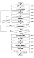
- FIG. 7 is a schematic flowchart showing an example of the overall operation of the one-scene skeleton recognition unit 120
- FIG. 8 is a schematic flowchart showing an example of the part recognition process.
- 9A and 9B are explanatory diagrams of the processing of FIG.
- point group data x n relating to a certain temporary point (one scene) is shown.
- step S702 the clustering unit 122 acquires an initial value used for fitting using a geometric model based on the point cloud data xn obtained in step S700.
- the details of the processing (initial value acquisition method) of the clustering unit 122 are as described above.
- step S704 the EM algorithm unit 124 executes the E step of the EM algorithm based on the point cloud data xn obtained in step S700 and the initial value obtained in step S702. Details of the E step of the EM algorithm are as described above.
- step S710 the EM algorithm unit 124 determines whether there is an unprocessed part, that is, whether j ⁇ M ′. If there is an unprocessed part, the process from step S706 is repeated through step S711. If there is no unprocessed part, the process proceeds to step S712.
- step S711 the EM algorithm unit 124 increments j by “1”.
- step S712 the EM algorithm unit 124 determines whether or not it has converged.
- the convergence condition for example, that the log-likelihood function is not more than a predetermined value or that the moving average of the log-likelihood function is not more than a predetermined value may be used.
- step S714 the model optimization unit 126 performs a model optimization process. For example, the model optimization unit 126 calculates the total part sum of the data sum of the posterior distribution related to the geometric model used this time. If the total part sum of the data sum of the posterior distribution is less than the predetermined reference value, the EM algorithm unit 124 is instructed to change the geometric model, and the processes from step S704 to step S712 are executed again. Alternatively, the model optimizing unit 126 instructs the EM algorithm unit 124 to change the geometric model regardless of the total part sum of the data sum of the posterior distribution related to the geometric model used this time. The process of S712 is executed again. In this case, the model optimizing unit 126 selects the geometric model having the largest sum of all parts of the data sum of the posterior distribution as the type of geometric model having the best fit.
- parameters ⁇ (r m , c m 0 , and e m 0 ) relating to a plurality of geometric models applied to the point cloud data x n are obtained. It is done.
- the geometric model M1 is a geometric model related to the head of the subject S
- the geometric model M2 is a geometric model related to the torso of the subject S
- the geometric models M3 and M4 are both arms of the subject S.
- the geometric models M5 and M6 are geometric models related to both legs of the subject S.
- the geometric models M1 to M6 are all cylindrical.
- step S716 the length calculation unit 128 determines the length parameter l m of each geometric model (see the geometric models M1 to M6) based on the point cloud data x n and the parameter ⁇ obtained in the processing up to step S714. Is derived. Deriving the length parameter l m includes deriving the length parameter l + m and the length parameter l ⁇ m with respect to the center of the part m as described above.
- step S7108 the part recognition unit 130 performs part recognition processing.
- the site recognition process is as described above, but an example procedure will be described later with reference to FIG.
- step S720 the skeleton shaping unit 132 performs a cutting process, a combining process, and a connecting process based on the part recognition process result obtained in step S718.
- the skeletal shaping unit 132 performs a cutting process on the part for which the cutting flag is set.
- the details of the cutting process are as described above.
- the coupling process is as described above, and includes deriving the straight lines related to the skeletons b14 and b15 related to the hip joint and the skeletons b4 and b7 related to the shoulder joint.
- the details of the connection process are as described above.
- step S720 When the processing up to step S720 is completed, as conceptually shown in FIG. 9B, the position of each joint related to the cutting processing, the hidden skeleton, and the like are derived.
- step S722 the calibration information generation unit 134 generates calibration information based on the processing results of steps S704 to S722 in the current cycle.
- the method for generating calibration information is as described above.
- step S718 the part recognition process in step S718 will be described with reference to FIG.
- step S800 the region recognition unit 130, the thickness r m, the difference between the thick portion in the first and second is equal to or greater than a predetermined value. If the determination result is “YES”, the process proceeds to step S802, and otherwise, the process proceeds to step S804.
- the region recognition unit 130 identifies the thickness r m greater portion m1 to the first as the barrel (straight elongated body portion), it sets the cut flag for site m1.
- the part to which the geometric model M2 is associated is the first thickest part m1 whose difference from the second thickest part is a predetermined value or more, and the cutting flag is set. .
- the cutting flag is set for the part m1 in this way, the cutting process is executed for the part m1 in step S720 of FIG.
- step S804 the region recognition unit 130, and a thickness r m greater part the second greater portion m1 to the first m2, identified as the barrel.
- step S806 the part recognition unit 130 recognizes the head.
- the part recognition unit 130 recognizes a part mh near the upper surface of the part m1 as a head.
- the part to which the geometric model M1 is associated is recognized as the head.
- step S808 the part recognizing unit 130 recognizes the left and right legs near the bottom of the trunk. That is, as described above, the part recognizing unit 130 identifies the left and right two joint points in the vicinity of the bottom surface of the trunk as the root joint point of each leg part, and the parts ml and mr having the two joint points are It is recognized as a part related to the leg part.
- step S810 the part recognizing unit 130 has joint points related to the other parts ml2 and mr2 on the end side (the side far from the trunk part) of the parts ml and mr related to the left and right legs recognized in step S808. It is determined whether or not. At this time, the part recognizing unit 130 determines the left and right leg parts separately. If the determination result is “YES”, the process proceeds to step S812, and otherwise, the process proceeds to step S814.
- step S814 the part recognition unit 130 recognizes the parts ml and mr related to the left and right legs recognized in step S808 as straight legs, and sets a cutting flag for the parts ml and mr. .
- the cutting flag is set for the parts ml and mr in this way, the cutting process is executed for the parts ml and mr in step S720 of FIG.
- step S816 the part recognizing unit 130 recognizes the left and right arms on the left and right side surfaces on the upper side of the trunk (the side far from the leg). That is, as described above, the part recognizing unit 130 identifies the two joint points included in the thin torus on the side surface of the torso as the root joint points of the respective arm parts, and the parts mlh, mrh having the two joint points. Is recognized as a part related to the left and right arms.
- step S820 the part recognition unit 130 recognizes the parts mlh and mrh related to the left and right arms recognized in step S816 as the upper arm part, and recognizes the other parts mlh2 and mrh2 recognized in step S818 as the forearm part. To do.
- step S720 of FIG. 7 the connection process is executed for the parts mlh and mlh2, and the connection process is executed for the parts mrh and mrh2.
- step S822 the part recognizing unit 130 recognizes the parts mlh and mrh related to the left and right arm parts recognized in step S816 as straight arms, and sets a cutting flag for the parts mlh and mrh. .
- the cutting flag is set for the parts mlh and mrh in this way, the cutting process is executed for the parts mlh and mrh in step S720 of FIG.
- FIGS. 7 and 8 it is possible to accurately recognize the joint or skeleton of the subject S based on the point cloud data xn of the subject S related to a certain temporary point (one scene). Become.
- the processing shown in FIGS. 7 and 8 may be repeatedly executed for each frame period.
- the parameters ⁇ and variance ⁇ 2 obtained in the previous frame and the previous frame are used.
- the parameter ⁇ or the like related to the next frame may be derived using the existing geometric model.
- the point group data x n has been formulated as being all near the geometric model surface, but the point group data x n includes noise and the like. If such data away from the surface is mixed, the posterior distribution of the E step may become unstable and may not be calculated correctly. Therefore, a uniform distribution may be added as a noise term to the distribution p (x n ) as follows.
- u is an arbitrary weight.
- the posterior distribution is corrected as follows.
- u c is defined as follows.
- first time point the time point related to the point cloud data x n used in the one-scene skeleton recognition unit 120
- second time point This is referred to as “time point”.
- time point the time point related to the point cloud data x n used in the minute fitting processing unit 150
- time point is later than the first time point, and here, for example, it is assumed that it is a minute time corresponding to one frame period.
- the part m is the same as the part of [1 scene skeleton recognition unit] described above except that the part m is a part to be fitted. Different. That is, in the one-scene skeleton recognition process, the part m may be simultaneously associated with two parts of the subject S as described above. However, in the following minute fitting process, the part m is 2 of the subject S. It is not associated with a part at the same time. Therefore, in the description of [micro fitting processing unit], the part m corresponds to each part of the 15 parts excluding the hidden skeleton (part) in the case of the joint model shown in FIG.
- the minute fitting processing unit 150 performs the minute fitting process using the calibration information generated by the one-scene skeleton recognition unit 120.
- a parameter related to the parameter ⁇ and representing the joint (joint rotation) of the subject S and the rotation and translation of the center of gravity of the subject S will be referred to as “deformation parameter ⁇ ar ”.
- the calibration information includes used geometric model information (information representing a geometric model used for each part in the one-scene skeleton recognition process).
- the geometric model used when the calibration information is obtained is succeeded. For example, when a cylinder is used for a certain part when generating calibration information, the cylinder is used for the part even in the micro-fitting process.
- the minute fitting processing unit 150 includes a surface residual calculation unit 151, a posterior distribution calculation unit 152, a finite length processing unit 154, a variance update unit 155, a minute change calculation unit 156, a parameter An updating unit 158.
- the surface residual calculation unit 151 calculates the surface residual ⁇ nm and the differential ⁇ ′ nm of the surface residual.
- the surface residual ⁇ m (x n , ⁇ ar ) (difference in the direction perpendicular to the surface) between the point cloud data x n and the part m is a Gaussian distribution, as in the above-described one-scene skeleton recognition process. Is assumed. Specifically, it is as follows.
- M is the total number of parts of the joint model (total number of all parts including hidden parts), and is “15” in the joint model shown in FIG. Therefore, M may be different from M ′ used in the one-scene skeleton recognition unit 120.
- h is the number of hidden skeletons (parts) (an example of the second part), and is “4” in the joint model shown in FIG. 4.
- the surface residual ⁇ nm and the differential ⁇ ′ nm of the surface residual are defined as follows. Note that ⁇ ar is a deformation parameter.
- ⁇ > p is similarly an average operation using the posterior distribution p nm , but is related to the difference between “M ′” and “Mh”. Then, for an arbitrary tensor or matrix a nm :
- the surface residual may be expressed as follows, for example.
- the position c m ⁇ and the direction e m ⁇ represent the position and orientation of the part m in a certain posture ⁇ .
- the position c m ⁇ is the position of the joint point on the ancestor side of the part m as already defined.
- the subscript l ′ indicates a movable part, and the total number is Mf (for example, 13).
- ⁇ ′ nml′i ′ is the derivative of the surface residual with respect to the movable part
- i ′ is the derivative of the surface residual with respect to the rotation of the center of gravity of the subject S
- i ′ is the derivative of the surface residual with respect to the translation of the center of gravity of the subject S.
- ⁇ ml ′ is the Kronecker delta and is as follows:
- the ancestor-descendant relationship can be determined based on the part correspondence information included in the calibration information.
- the surface residual ⁇ m (x n , ⁇ ar ) may be expressed as: Note that, in a cone (the same applies to an elliptical cone), the position c m ⁇ corresponds to the vertex position in a certain posture ⁇ , and the direction e m ⁇ in a certain posture ⁇ is a unit vector of the central axis.
- Equation 22 The vector nm is as described above with respect to Equation 22. In the case of a trapezoidal column, it may be the same as in the case of a cone. In the case of an elliptic cylinder, the surface residual ⁇ m (x n , ⁇ ar ) may be expressed as follows.
- the surface residual ⁇ m (x n , ⁇ ar ) may be expressed as follows.
- ⁇ m1 and the like are as described above with respect to Equation 24.
- the surface residual ⁇ m (x n , ⁇ ar ) may be the same as in the case of an elliptical cone.
- Posterior distribution calculating unit 152 calculates the posterior distribution p nm in micro-fitting process.
- the posterior distribution p nm in the minute fitting process is as follows in relation to the difference between “M ′” and “Mh”.
- the finite length processing unit 154 performs finite length processing based on the posterior distribution pm obtained by the posterior distribution calculating unit 152.
- the finite length process is a process in which the posterior distribution p nm is calculated only for data satisfying a predetermined condition among the point cloud data x n and the posterior distribution p nm is set to 0 for other data. is there.
- the data satisfying the predetermined condition may be data satisfying the following expression, for example.
- l m is the length parameter included in the calibration information (i.e. the length of the portion m derived by the length calculator 128 parameter l m).
- the variance update unit 155 derives (updates) the variance ( ⁇ 0 2 + ⁇ 2 ) after the minute change.
- the likelihood function maximization problem can be derived by linear approximation. That is, by setting the derivative with respect to ⁇ 2 in the equation (39) to 0, the variance ( ⁇ 0 2 + ⁇ 2 ) after a minute change is obtained.
- the variance ⁇ 0 2 is an initial value and is obtained by the one-scene skeleton recognition unit 120.
- the dispersion ( ⁇ 0 2 + ⁇ 2 ) after a minute change may be as follows.
- the minute change calculation unit 156 calculates a minute change ⁇ of the deformation parameter ⁇ ar .
- the likelihood function maximization problem can be derived by linear approximation as follows, similarly to the variance ⁇ 2 . That is, since the second time point is a minute later than the first time point, the point cloud data x n at the second time point is not expected to change significantly from the point cloud data x n at the first time point. . For this reason, it is expected that the deformation parameter ⁇ ar at the second time point does not change significantly from the deformation parameter ⁇ ar at the first time point. Accordingly, it is assumed that the deformation parameter ⁇ ar at the second time point is represented by a minute change ⁇ from the deformation parameter ⁇ ar at the first time point.
- the minute change ⁇ of the deformation parameter ⁇ ar is as follows using the surface residual ⁇ nm and the differential ⁇ ′ nm of the surface residual (see Equation 40).
- the parameter updating unit 158 calculates the respective changes ⁇ c k ⁇ and ⁇ e k ⁇ (an example of the second parameter) of the position c k ⁇ and the direction e k ⁇ . deriving (updated) doing, located c k ⁇ + ⁇ and derives the orientation e k ⁇ + ⁇ (updated). Note that the position c k ⁇ and the direction e k ⁇ represent the position and orientation of the part k in a certain posture ⁇ as described above. As the initial values of the position c k ⁇ and the direction e k ⁇ , the position c k ⁇ 0 and the direction e k ⁇ 0 included in the calibration information are used.
- ⁇ c k ⁇ and ⁇ e k ⁇ can be derived as follows based on the forward kinematics of the mechanism model.
- ⁇ l′ i ′ , ⁇ M ⁇ f + 1, i ′ , and ⁇ M ⁇ f + 2, i ′ are each element of the minute change ⁇ .
- ⁇ M ⁇ f + 1, i ′ represents the rotation of the center of gravity of the subject S.
- i ′ represents the translation of the center of gravity of the subject S.
- i ′ represents three degrees of freedom of rotation
- i ′ 0, X, XX.
- d is the spatial dimension
- d 3.
- F is the number of joints that are not movable.
- the non-movable joint is, for example, a joint (see a joint a0 in FIG. 4) related to the pelvis (see the parts b14 and b15 in FIG. 4).
- Equations 43, 44 and 45 and Equation 55 are expressed by Equations 43, 44 and 45 and Equation 55, respectively.
- ⁇ ′ nml′i ′ is a differential of the surface residual for obtaining ⁇ l′ i ′ in the equations 58 and 59 from the above equation 55.
- ⁇ ′ nm, M ⁇ f + 1, i ′ is a differential of the surface residual for obtaining ⁇ M ⁇ f + 1, i ′ in the equations 58 and 59 from the above equation 55.
- ⁇ ′ nm, M ⁇ f + 2, i ′ is a derivative of the surface residual for obtaining ⁇ M ⁇ f + 2, i ′ in the equation 58 from the above equation 55. It should be noted that geometric models other than the cylinder can be similarly derived using the above-described surface residual.
- n is an arbitrary unit vector (fixed vector), and may be a unit vector related to the direction of the distance image sensor 21, for example.
- ⁇ kl ′ is a Kronecker delta, which is the same as described above.
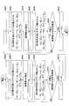
- the part numbers in FIG. 10 are as shown in FIG.
- the numbers of the non-movable pelvis parts are the last two “14” and “15” and are excluded from the row.
- a row and a column indicate the same part with the same number.
- the subscript k indicates all parts, and the total number is M.
- the subscript m indicates the part to be fitted, and the total number is Mh.
- the subscript l ′ indicates the movable part, and the total number is M ⁇ f.
- ⁇ c k ⁇ and ⁇ e k ⁇ can be derived by substituting ⁇ l′ i ′ , ⁇ M ⁇ f + 1, i ′ , and ⁇ M ⁇ f + 2, i ′ into Equations 58 and 59. Become. When ⁇ c k ⁇ and ⁇ e k ⁇ are obtained, the position c k ⁇ + ⁇ and the direction e k ⁇ + ⁇ of the part k can be derived based on the update formulas of Formulas 56 and 57.
- an axially symmetric geometric model such as a cylinder or a trapezoidal column is excluded because the degree of freedom of rotation about the axis is indefinite.
- an axisymmetric geometric model has two degrees of freedom excluding the degree of freedom around the axis.
- ⁇ l'0, ⁇ l'X and of the [Delta] [theta] l'XX, [Delta] [theta] except joint rotation [Delta] [theta] l'0 around axis l'X and [Delta] [theta] l'XX only Is calculated.
- calculation load can be reduced efficiently.
- it when it is desired to obtain the rotation angle of the actual movable shaft, it can be obtained by conversion using a rotation matrix.
- FIG. 12 is a schematic flowchart showing an example of the overall operation of the object recognition system 1.
- the data input unit 110 acquires information indicating a joint model to be used.
- the data input unit 110 acquires information indicating the joint model illustrated in FIG.
- the information indicating the joint model may be information indicating the number of joints (number of parts), a connection relationship, a part to be fitted, a movable joint, and the like.
- step S1202 the data input unit 110 determines whether a predetermined processing end condition is satisfied.
- the predetermined processing end condition is that processing of all point cloud data to be processed (for example, point cloud data at a plurality of points in time and a series of time series data) is completed. May be satisfied.
- the predetermined processing end condition may be satisfied when an end instruction is input from the user, or when point cloud data related to the current frame period is not input. If the determination result is “YES”, the process ends as it is, and otherwise, the process proceeds to step S1204.
- step S1203 the data input unit 110 increments jj by “1”.
- step S1204 the data input unit 110 acquires the point cloud data relating to the jj-th (that is, the jj-th frame) in time series, which is point cloud data relating to one time point to be processed. For example, when processing in real time, the point cloud data related to the current frame cycle becomes the point cloud data related to one time point to be processed.
- step S1206 the one-scene skeleton recognition unit 120 performs a one-scene skeleton recognition process based on the point cloud data obtained in step S1204.
- One scene skeleton recognition processing is as described above.
- the one-scene skeleton recognition unit 120 determines whether the one-scene skeleton recognition process is successful. Specifically, when the one-scene skeleton recognition unit 120 determines that calibration information (position c k ⁇ 0, orientation e k ⁇ 0, etc.) satisfying the first predetermined criterion is derived in the one-scene skeleton recognition process, It is determined that the scene skeleton recognition process is successful. For example, the one-scene skeleton recognition unit 120 can recognize a predetermined number of parts and the calibration information satisfying the first predetermined standard is obtained when the data sum of the posterior distribution of each part is equal to or greater than a predetermined value Th1. It is determined that it has been derived.
- calibration information position c k ⁇ 0, orientation e k ⁇ 0, etc.
- the predetermined number of parts may correspond to all parts (all parts defined by the joint model) except the hidden part. By evaluating the data sum of the posterior distribution of each part, it is possible to generate calibration information when all parts are recognized with high accuracy. If the determination result is “YES”, the process proceeds to step S1210, and otherwise, the process proceeds to step S1212.
- step S1210 it is determined whether a predetermined processing end condition is satisfied.
- the predetermined processing end condition may be the same as in step S1202. If the determination result is “YES”, the process ends as it is, and otherwise the process proceeds to step S1212.
- step S1211 the data input unit 110 increments jj by “1”.
- step S ⁇ b> 1212 the data input unit 110 acquires point cloud data relating to the jjth point in time series, which is point cloud data relating to one time point to be processed.
- step S1214 the microfitting processing unit 150 performs a microfitting process based on the calibration information when successful in step S1208 and the point cloud data obtained in step S1212.
- the point cloud data used here is the point cloud data obtained in step S1212 and relates to a time point (second time point) after the time point (first time point) related to the point cloud data obtained in step S1204.
- step S1216 the microfitting processing unit 150 determines whether the microfitting process has been successful. Specifically, when it is determined that the position c k ⁇ and the direction e k ⁇ satisfying the second predetermined criterion have been derived by the micro fitting process, the micro fitting processing unit 150 determines that the micro fitting process has been successful. For example, if the total part sum of the data sum of the posterior distribution is greater than or equal to a predetermined value Th2, the minute fitting processing unit 150 determines that the position c k ⁇ and the direction e k ⁇ satisfying the second predetermined criterion have been derived.
- the minute fitting process can be continued. This is because in microfitting, the missing part is only joint rotation, so that the movement of the subject S is not largely lost.
- the minute fitting can be estimated from the remaining data if it is a partial defect.
- step S1210 a minute fitting process based on the point cloud data relating to the next frame is executed. On the other hand, if the determination result is “NO”, the process returns to step S1202, and the one-scene skeleton recognition process is performed again.
- the minute fitting process can be performed based on the recognition result. it can. Thereby, the processing speed can be increased as compared with the case where the one-scene skeleton recognition process is repeated for each frame. Further, when the recognition accuracy is deteriorated in the subsequent minute fitting process (when the total part sum of the data sum of the posterior distribution becomes less than the predetermined value Th2), the one-scene skeleton recognition process can be performed again. As a result, it is possible to suppress inconvenience caused by continuing the minute fitting process more than necessary, that is, deterioration of recognition accuracy. In this way, according to the processing shown in FIG. 12, it is possible to achieve both improvement in processing speed and securing of highly accurate recognition results.
- the surface residual calculation unit 151 calculates the surface residual ⁇ nm and the differential ⁇ ′ nm of the surface residual related to the part m.
- the calculation method of the surface residual ⁇ nm and the differential ⁇ ′ nm of the surface residual is as described above.
- the calculation of the surface residual ⁇ nm and the surface residual differential ⁇ ′ nm related to the part m depends on the geometric model associated with the part m. For example, in the case where the geometric model is a cylinder, the equations shown in Equations 42 to 45 may be used.
- step S1304 the posterior distribution calculation unit 152 calculates the posterior distribution p nm related to the part m based on the point cloud data obtained in step S1212 and the surface residual ⁇ nm obtained in step S1302.
- the calculation method of the posterior distribution p nm is as described above (see Formula 51).
- step S1306 the finite length processing unit 154 performs finite length processing based on the posterior distribution p nm obtained in step S1304.
- the finite length processing is as described above (see Formula 52).
- step S1312 the minute change calculation unit 156 calculates the minute change ⁇ .
- This calculation can be realized by matrix operation, for example.
- step S1316 the parameter update unit 158 derives the position c k ⁇ + ⁇ and the direction e k ⁇ + ⁇ based on the minute change ⁇ obtained in step S1312, and the position c k ⁇ and the direction e k ⁇ are derived. Update with k ⁇ + ⁇ and orientation e k ⁇ + ⁇ .
- the method for deriving the position c k ⁇ + ⁇ and the direction e k ⁇ + ⁇ is as described above.
- the initial values of the position c k ⁇ and the direction e k ⁇ are the position c k ⁇ 0 and the direction e k ⁇ 0 , and are obtained in the most recent step S1206.
- M is the total number of all sites as described above.
- the position c k ⁇ and the direction e k ⁇ can be updated at a relatively high processing speed by using the result of the one-scene skeleton recognition process obtained in step S1206 of FIG. .
- a processing speed of N times speed can be realized as compared with a case where N iterations are performed for each frame.
- the process of step S1316 may be realized by parallel processing.
- the position c k ⁇ can be calculated for only one part because it can be derived for another part if it is obtained for one part. May be.
- synchronization waiting occurs when the computations of the respective parts are parallelized.
- both the position c k ⁇ and the direction e k ⁇ are calculated at each part, such a synchronization wait can be avoided.
Landscapes
- Engineering & Computer Science (AREA)
- Physics & Mathematics (AREA)
- General Physics & Mathematics (AREA)
- Theoretical Computer Science (AREA)
- Multimedia (AREA)
- Computer Vision & Pattern Recognition (AREA)
- Human Computer Interaction (AREA)
- Bioinformatics & Computational Biology (AREA)
- Bioinformatics & Cheminformatics (AREA)
- Evolutionary Biology (AREA)
- Probability & Statistics with Applications (AREA)
- Computational Linguistics (AREA)
- Software Systems (AREA)
- Health & Medical Sciences (AREA)
- General Health & Medical Sciences (AREA)
- Psychiatry (AREA)
- Social Psychology (AREA)
- Life Sciences & Earth Sciences (AREA)
- Image Analysis (AREA)
Abstract
Description
前記対象物の複数の部位のそれぞれの位置及び軸方向を表す第1パラメータであって、第1時点での第1パラメータを導出又は取得し、
前記第1時点より後の第2時点での前記点群データと、前記第1時点での前記第1パラメータと、軸を有する幾何モデルとに基づいて、前記第2時点での前記第1パラメータを導出することを含む、コンピュータにより実行される対象物認識方法が提供される。
1シーン骨格認識部120は、クラスタリング部122と、EMアルゴリズム部124と、モデル最適化部126と、長さ算出部128とを含む。また、対象物認識装置100は、更に、部位認識部130と、骨格整形部132と、キャリブレーション情報生成部134とを含む。

ここで、p(xn)は、点群データxnの混合確率分布モデルであり、上述のように、σ2は、分散であり、M'は、クラスタリング部122で得たクラスタ数が用いられる。このとき、対応する対数尤度関数は、以下のとおりである。

ここで、Nは、データ数(1フレームに係る点群データに含まれるデータ数)である。
εm(xn,θ)=|(xn-em 0)×em 0|-rm
但し、本実施例では、線形化のため、表面残差εm(xn,θ)は、数2の中での指数部分が二乗の差となるように表現され、具体的には以下のとおりである。
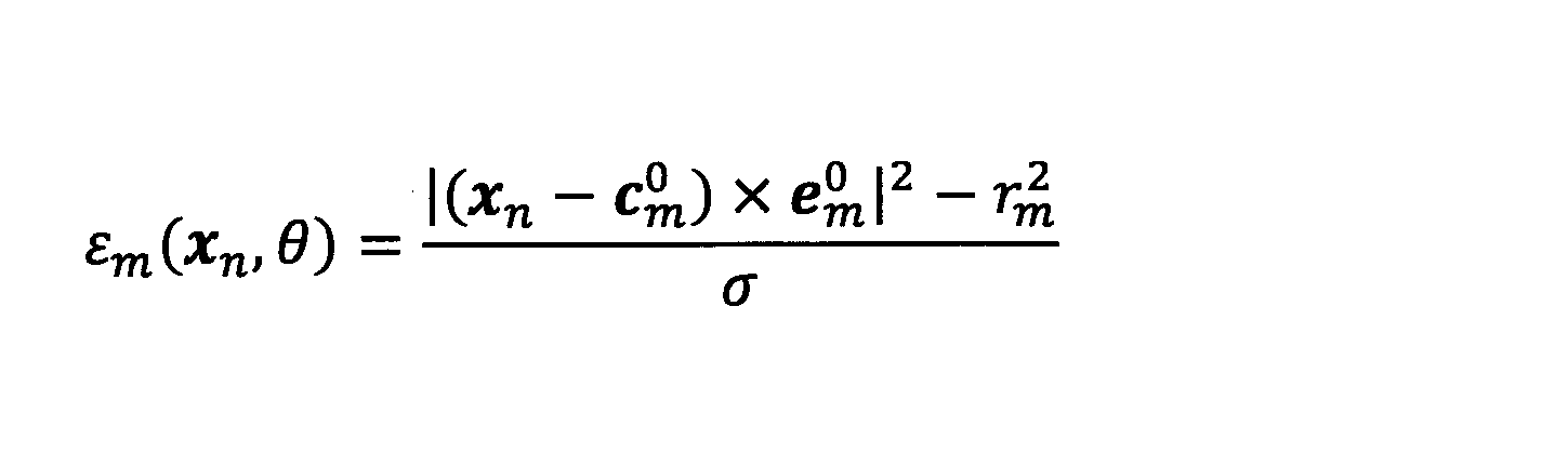
EMアルゴリズムは、知られているように、期待値を算出するEステップと、期待値を最大化するMステップの繰返しである。
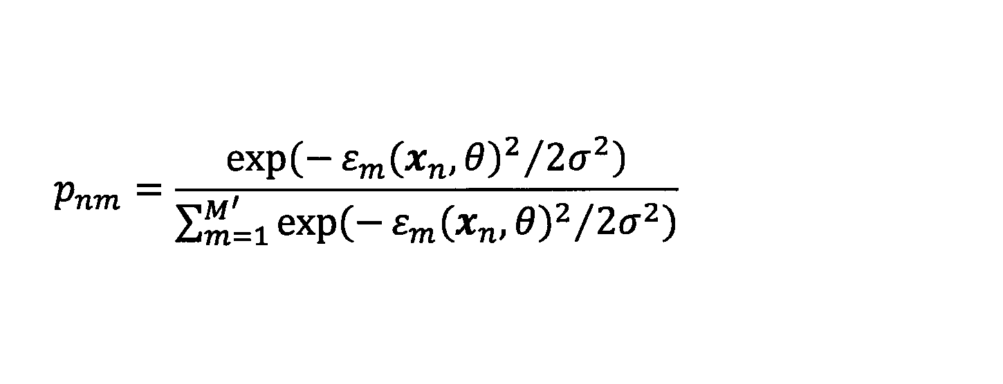
Mステップでは、EMアルゴリズム部124は、以下の期待値Q(θ,σ2)を最大化するパラメータθ及び分散σ2を導出する。尚、Mステップでは、事後分布pnmは定数として扱われる。
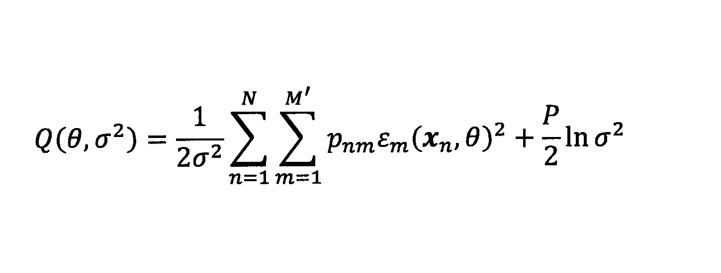
ここで、Pは、事後分布pnmのデータ和の全部位の和(以下、「事後分布pnmのデータ和の全部位和」とも称する)であり、以下のとおりである。

期待値Q(θ,σ2)の分散σ2による偏微分から、期待値Q(θ,σ2)を最大化する分散σ2の推定値σ2 *は、以下のとおりである。
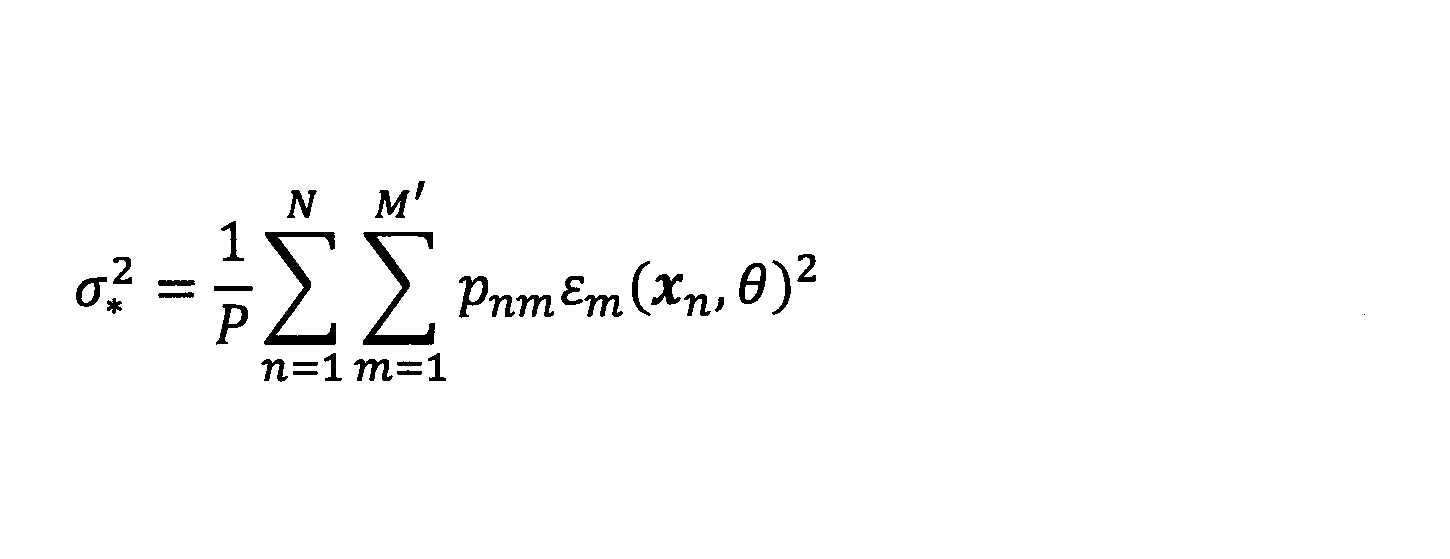
この推定値σ2 *を数5の式に代入すると、以下のとおりである。

パラメータθの各要素(rm、cm 0、及びem 0)に関して、太さrmの推定値r*mは、以下の通り、直接的に最小化が可能である。
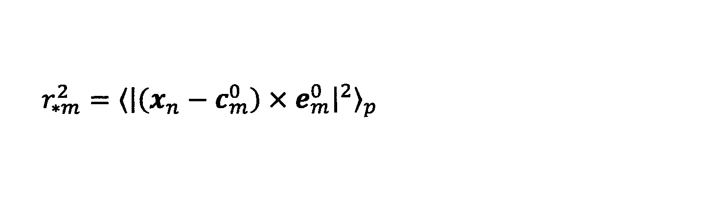
ここで、数9における表現〈〉pについて、事後分布pnmを用いた平均操作であり、任意のテンソルないし行列Anmに対して、以下の通りとする。

向きem 0の推定値e*m 0は、点群データの主成分であることに着目すると、主成分分析に基づいて導出できる。即ち、向きem 0の推定値e*m 0は、以下の分散共分散行列σxxの最も固有値の大きい固有ベクトルの向きとして求めることができる。
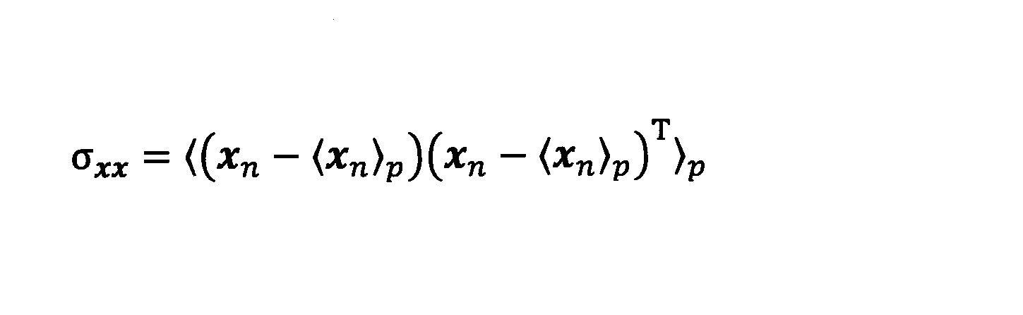
尚、数10に示す平均操作により、mについては和をとっていない。従って、〈xn〉pは、部位mに対する依存性を有し、部位mに係る幾何モデル(円柱)の重心(中心)に対応する。同様に、分散共分散行列σxxも部位mに固有であり、部位mに係る幾何モデル(円柱)の向きに対応する。
或いは、期待値Q(θ,σ2)は、パラメータθの各要素(rm、cm 0、及びem 0)に関して非線形であるので、向きem 0は、線形近似により導出されてもよい。具体的には、微小回転による更新式は、ノルムが保存される態様で規定され、以下のとおりである。
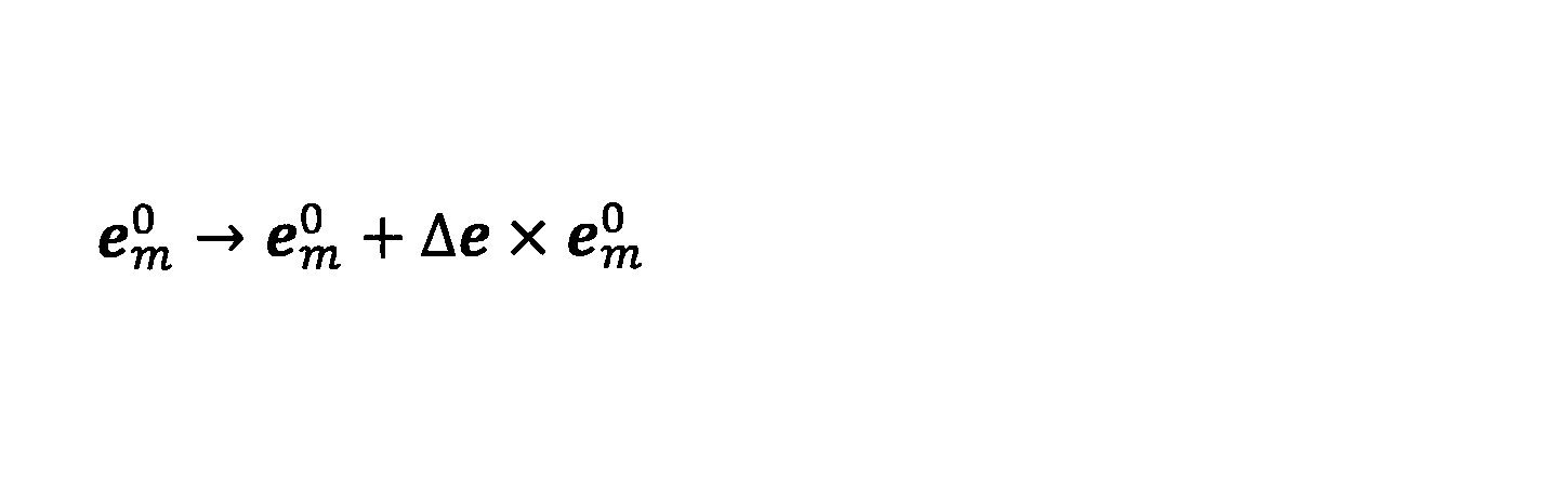
ここで、Δeは、微小回転ベクトルである。このとき、Δeの推定値Δe*は、数8の式をΔeで微分することで得られ、以下のとおりである。
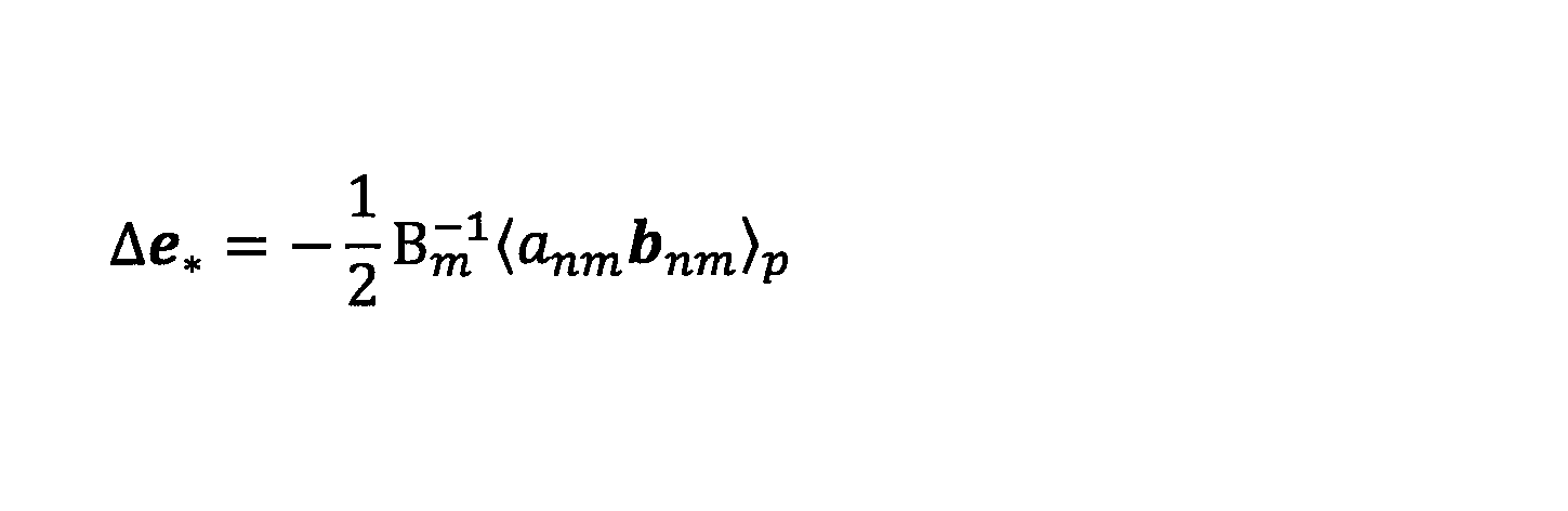
ここで、Bmの逆行列は、以下の通りであり、

数14におけるWは、以下の通りである。

尚、数14や数15において(以下も同様)、Tは、転置を表す。数15において、e1及びe2は、向きem 0に対して直交する単位ベクトルである。
また、数13におけるanmやbnmは、以下のとおりである(図4に示した関節a0~a15や骨格b1~b15の表記とは無関係である)。


よって、向きem 0の推定値e*m 0は、以下の通りである。

このとき、太さrmの推定値r*mを数8の式に代入し、位置cm 0の偏微分から、位置cm 0の推定値c*m 0は、以下の通り、直接的に導出可能である。

ここで、共分散行列σyyの逆行列、及び、ベクトルσy2y(下付き「y2y」)、以下のとおりである。


尚、上記の場合、EMアルゴリズム部124は、まず、位置cm 0の推定値c*m 0を求めてから、太さrmの推定値r*mを求めることになる。

ここで、位置cm 0は頂点位置に対応し、向きem 0は、中心軸の単位ベクトルである。また、ベクトルnmは、円錐の表面上のある1点における法線ベクトルである。
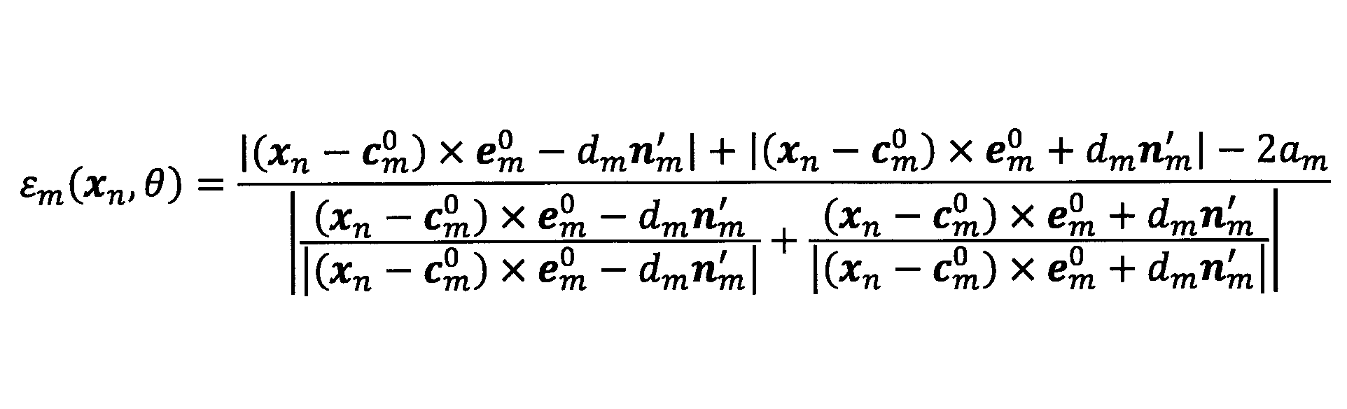
ここで、dmは、焦点距離であり、amは、断面の楕円の長軸の長さであり、nm 'は、長軸方向の単位ベクトルである。尚、同様に、位置cm 0は軸上の位置に対応し、向きem 0は、楕円柱の軸(軸方向)の単位ベクトルである。

ここで、ψm1及びψm2は、それぞれ長軸及び短軸方向への傾斜角である。また、同様に、位置cm 0は頂点位置に対応し、向きem 0は、中心軸の単位ベクトルである。

ここで、lm 0は、部位mに係る入力長さであり、αはマージン(例えば1.2)である。数25によれば、点群データのうちの、幾何モデルの中心(又は中心位置、以下同じ)からの軸方向の距離が所定距離(=αlm 0)以上のデータに対し、事後分布が0とされる。入力長さlm 0は、手入力することも可能であるし、他の計測によって得られる対象者Sの形状情報に基づいて設定されてもよい。

尚、Cは、定数倍の補正値である。
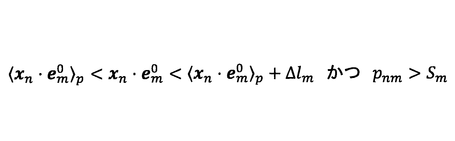
〈xn・em 0〉pは、部位mの中心に対応する。Δlmは、輪切りの幅(軸方向em 0に沿った幅)に対応し、例えば0.01lm 0である。尚、lm 0は、上述のように、部位mに係る入力長さである。Smは、事後分布pnmに対する閾値であり、例えば0.1である。
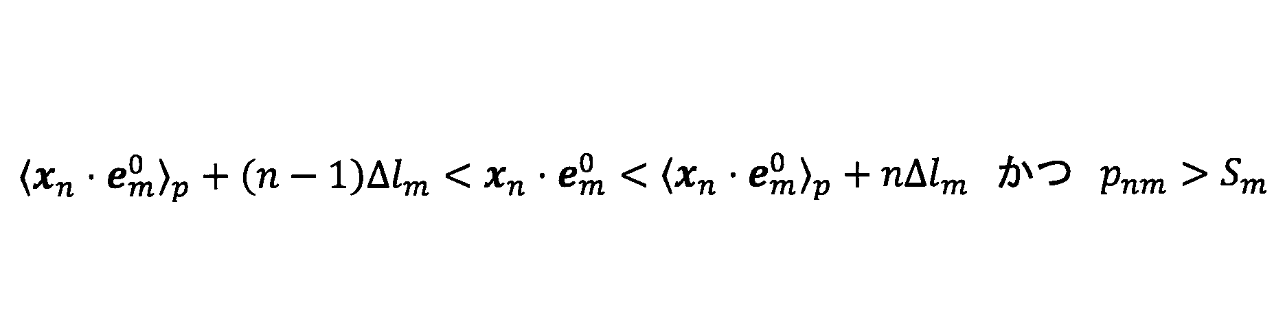
ステップS610では、長さ算出部128は、ステップS608でカウントしたデータ数が、基準値Crefの所定数倍(例えば0.5倍)以下であるか否かを判定する。判定結果が"YES"の場合は、ステップS612に進み、それ以外の場合は、ステップS606からの処理を繰り返す。

ここで、Nmは、以下で定義されるnの部分集合であり、ある閾値pm thより事後分布pnmが小さいnの集合である。
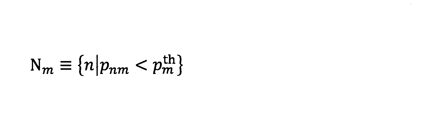
閾値pm thは、例えば、以下の通りである。
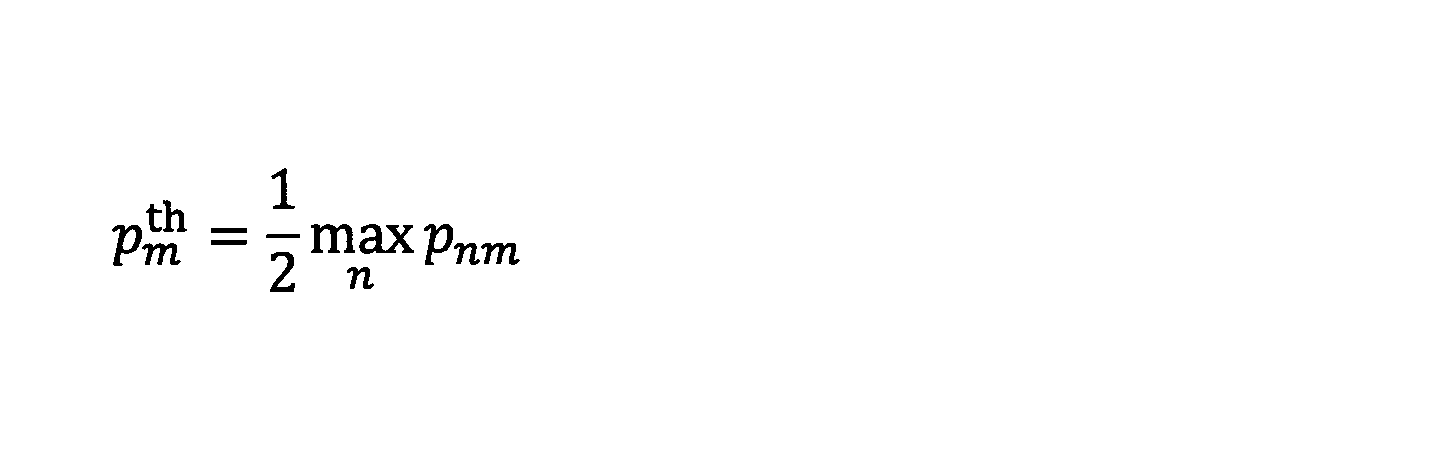
これは、部分集合Nmは、点群データxnのうちの、部位mに属さないデータの集合を表す。従って、長さ算出部128は、部分集合Nmのうちの、中心からの距離(数29の|xn・em 0-〈xn・em 0〉p|)が最小となるデータに基づいて、部位mの長さパラメータlmを算出していることになる。
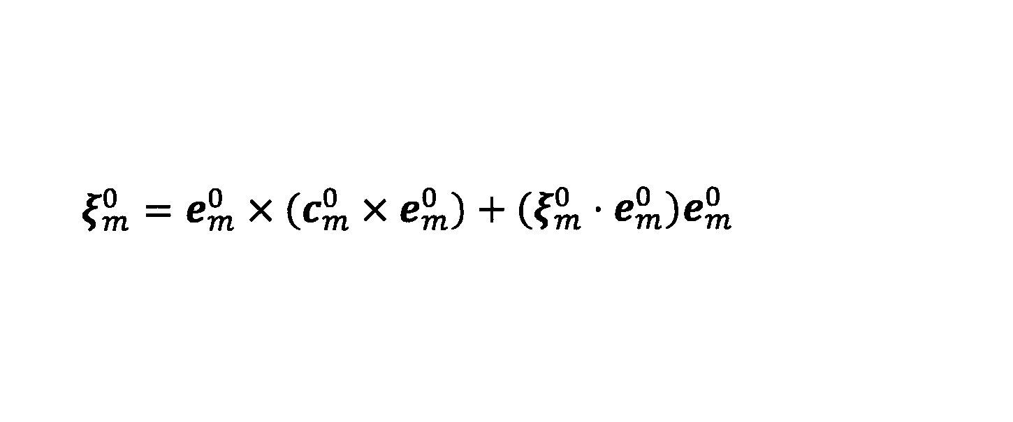
このとき、数32の右辺第2項は、祖先側の端部と、子孫側の端部とで以下の通りとなる。
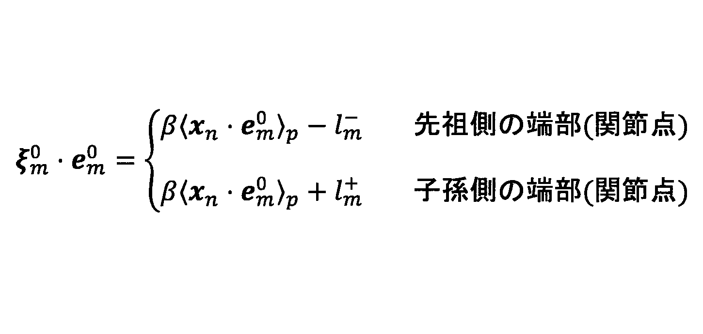
ここで、l+ mは、上述のように、部位mの中心(=〈xn・em 0〉p)からの子孫側への長さパラメータであり、l- mは、部位mの中心からの祖先側への長さパラメータであり、上述のように長さ算出部128により算出される。βは、定数であり、例えば1であってよい。
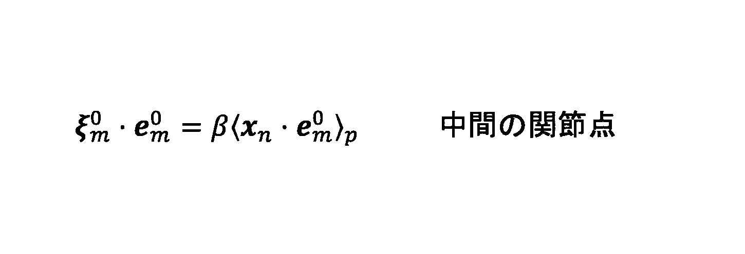
上述のように、βは、定数であり、例えば1であってよい。β=1の場合は、部位mの中心(=〈xn・em 0〉p)が、本来2部位からなる部位mの中間の関節点を表すことになる。或いは、βは、他の計測によって得られる対象者Sの形状情報に基づいて設定されてもよい。

ここで、uは任意の重みである。このとき、事後分布は以下のように修正される。

ここで、ucは、以下の通り定義される。
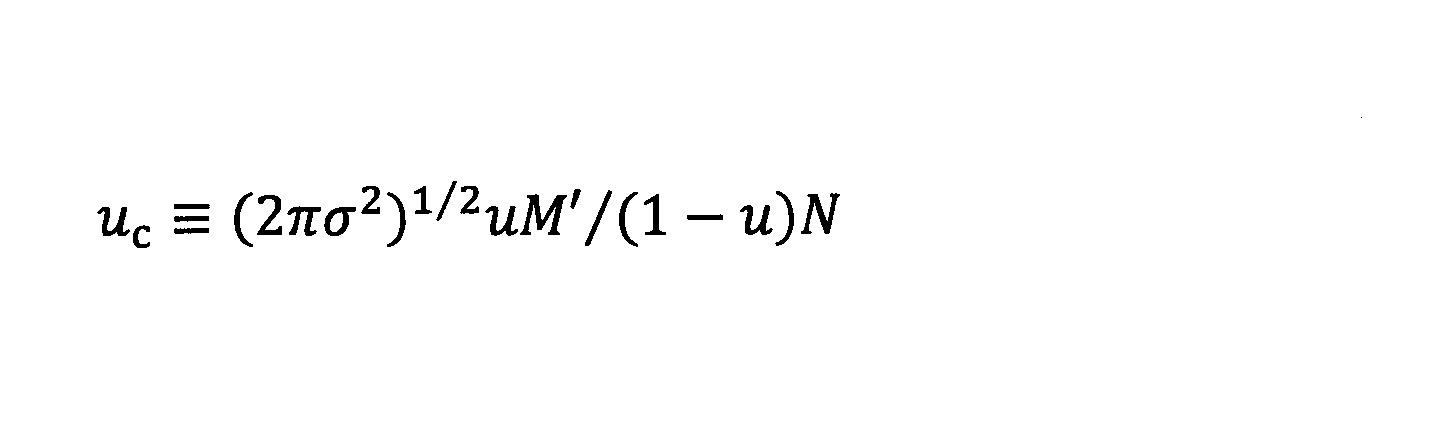
これにより、分母にucが導入され、数値不安定が解消される。尚、Eステップのみの変更であり、Mステップはそのままでよい。
以下の[微小フィッティング処理部]の説明において用いる記号は、特に言及しない限り、上記の[1シーン骨格認識部]の説明で用いた記号と実質的に同じ意味である。尚、点群データxnについては、同じ記号"xn"を用いるが、上述のように、微小フィッティング処理部150で用いられる点群データxnは、1シーン骨格認識部120で用いる点群データxnよりも後の時点(フレーム)で得られるデータである。以下では、1シーン骨格認識部120で用いる点群データxnに係る時点を、「第1時点」と称し、微小フィッティング処理部150で用いられる点群データxnに係る時点を、「第2時点」と称する。繰り返しになるが、第2時点は、第1時点よりも後であり、ここでは、例えば1フレーム周期に対応する微小時間だけ後であるとする。

ここで、Mは、関節モデルの全部位数(隠れた部位を含む全部位の総数)であり、図4に示す関節モデルでは、"15"である。従って、Mは、1シーン骨格認識部120で用いられるM'とは異なり得る。hは、隠れた骨格(部位)(第2部位の一例)の数であり、図4に示す関節モデルでは、"4"である。「M-h」を用いるのは、フィッティングに寄与しない部位を除外するためである。即ち、M-hは、微小フィッティング処理でフィッティング対象となる部位(第1部位の一例)の数である。1シーン骨格認識部120で用いられる「M'」に代えて、「M-h」を用いるのは、常にM'=M-hとなるとは限らないためである。また、固定値「M-h」とできるのは、微小フィッティング処理では、1シーン骨格認識処理とは異なり、手や脚などが真っ直ぐに伸びた状態でも、各部位を追跡できるためである。このとき、対応する対数尤度関数は、以下のとおりである。

表面残差εnm、及び、表面残差の微分ε'nmは、以下の通り定義される。尚、θarは、変形パラメータである。
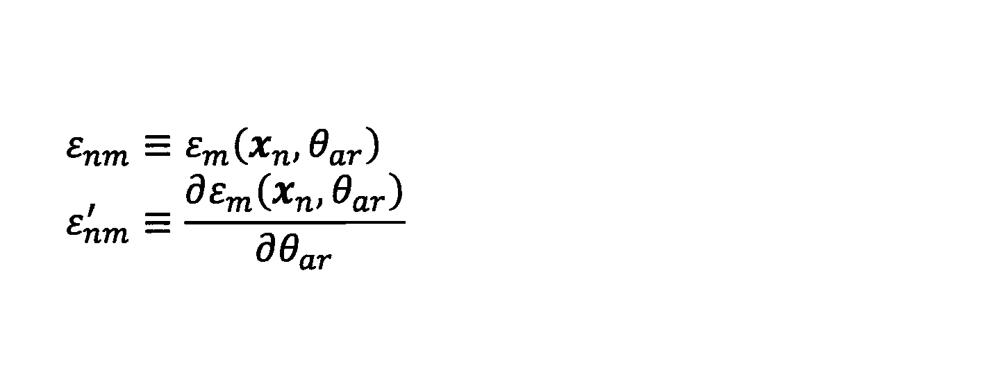
尚、[微小フィッティング処理部]の説明においては、表現〈〉pについては、同様に事後分布pnmを用いた平均操作であるが、「M'」と「M-h」との相違に関連して、任意のテンソルないし行列anmに対して、以下の通りとする。
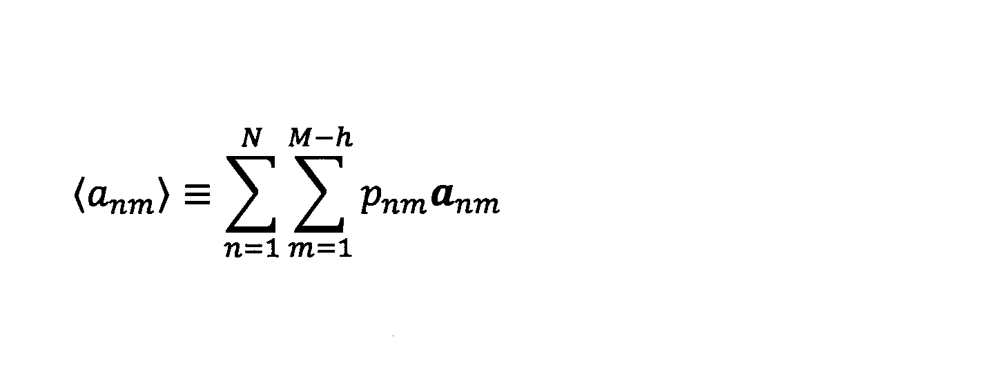
幾何モデルが円柱の場合、表面残差は、例えば以下の通り表現されてよい。ここで、位置cm Θ及び向きem Θは、ある姿勢Θにおける部位mの位置及び向きを表す。尚、位置cm Θは、既に定義したとおり、部位mの祖先側の関節点の位置である。
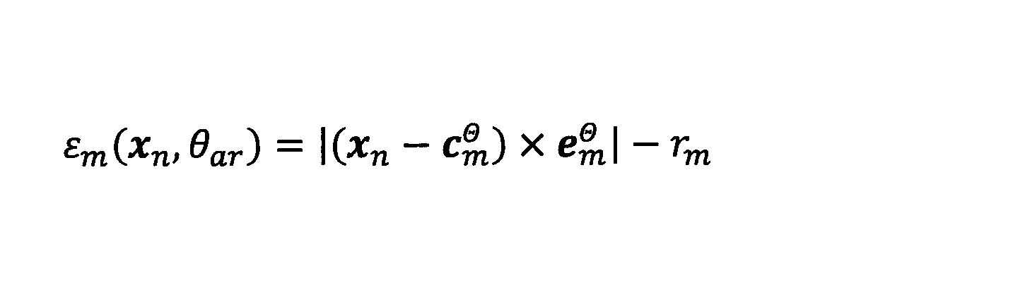
尚、数42では右辺が二乗同士の差となっていないが、上記の数3のように二乗の項が使用されてもよい。尚、1シーン骨格認識処理では、指数部分を二乗の差とすることで式が線形化されている。
このとき、表面残差の微分は、以下のとおりである。
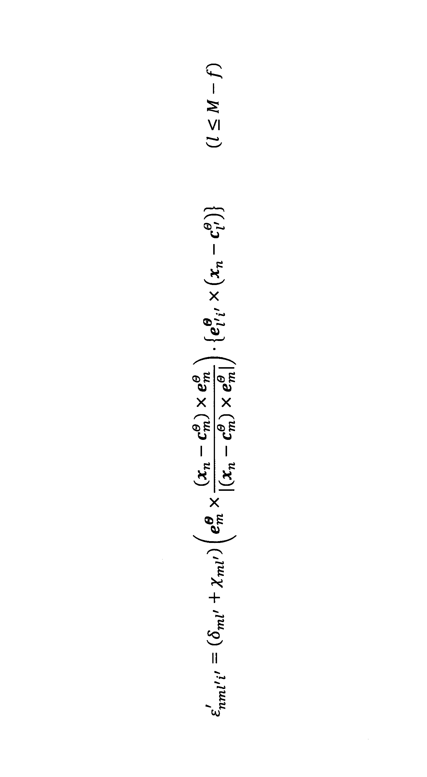

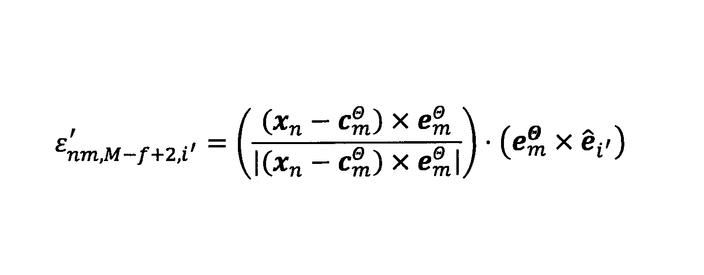
ここで、添字l'は、可動部位を指し、総数はM-f(例えば13)である。ε'nml'i'は、可動部位に関する表面残差の微分であり、ε'nm,M-f+1,i'は、対象者Sの重心の回転に関する表面残差の微分であり、ε'nm,M-f+2,i'は、対象者Sの重心の並進に関する表面残差の微分である。
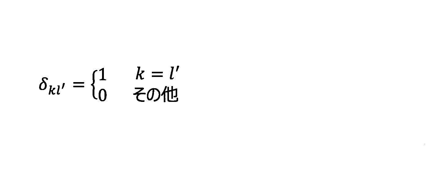
また、χml'は、以下のとおりである。

χml'は、部位mと部位l'(l'=1,2、・・・、13)との祖先・子孫関係を表すパラメータであり、祖先・子孫関係を表すパラメータについては、部位kと部位l'とに関連して、図10及び図11を参照して後述する。尚、祖先・子孫関係は、キャリブレーション情報に含まれる部位対応関係情報に基づいて判断できる。

ベクトルnmは、数22に関して上述した通りである。台形柱の場合、円錐の場合と同様であってよい。また、楕円柱の場合、表面残差εm(xn,θar)は、以下の通り表現されてよい。
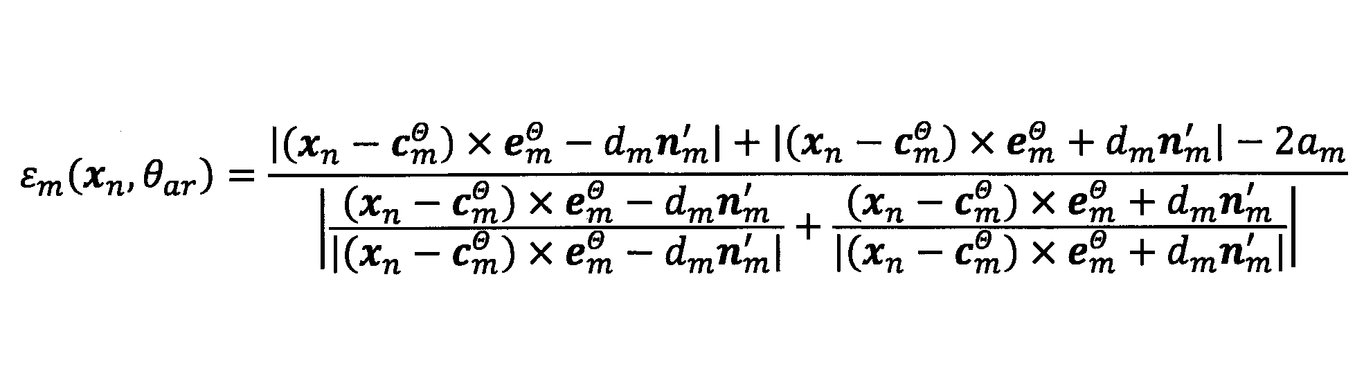
dm等は、数23に関して上述した通りである。
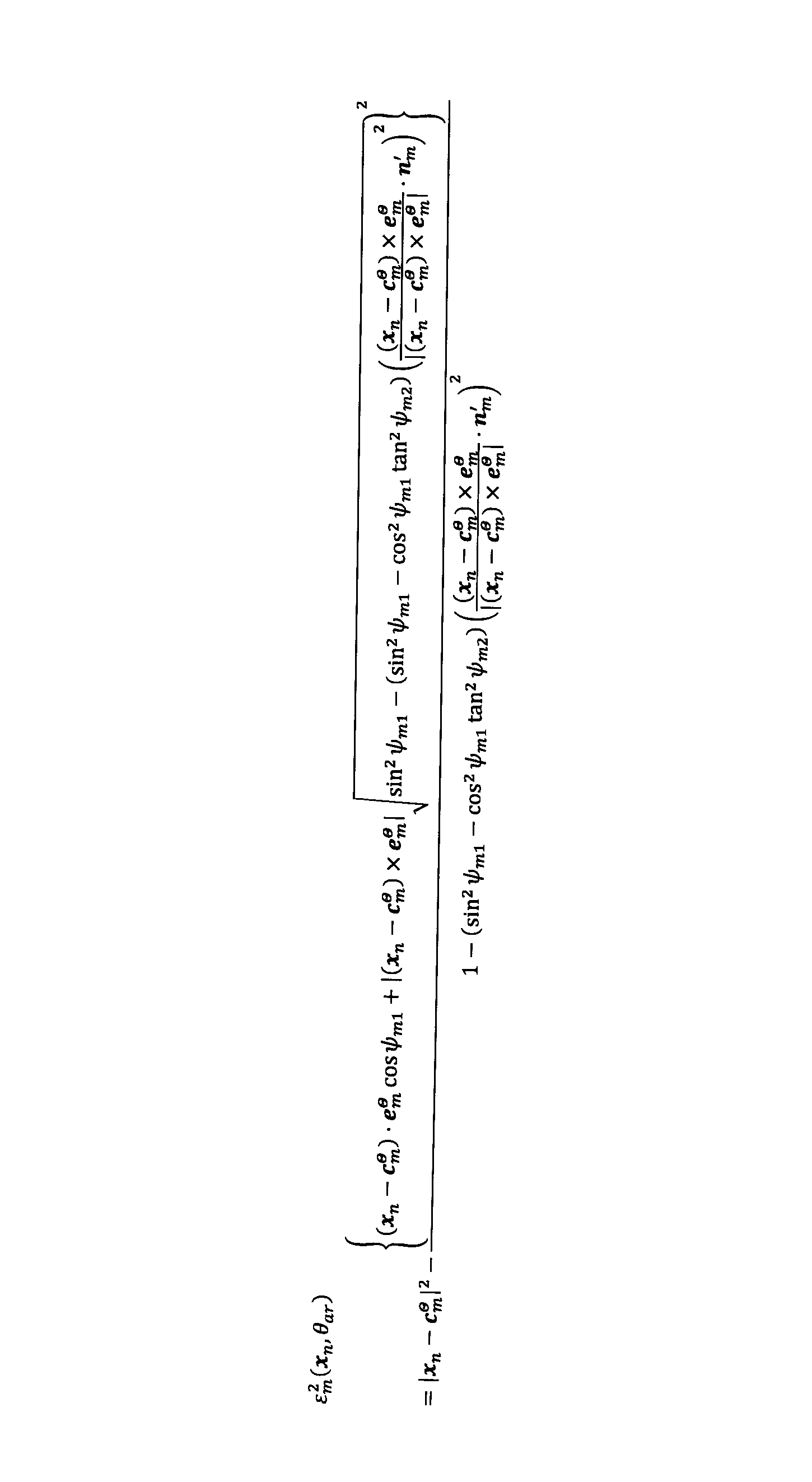
ψm1等は、数24に関して上述した通りである。台形楕円柱の場合、表面残差εm(xn,θar)は、楕円錐の場合と同様であってよい。
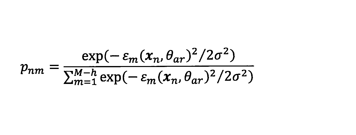
有限長処理部154は、事後分布算出部152で得られる事後分布pnmに基づいて、有限長処理を行う。有限長処理は、上述のように、点群データxnのうちの、所定の条件を満たすデータについてのみ事後分布pnmを算出し、他のデータについては事後分布pnmを0とする処理である。微小フィッティング処理では、所定の条件を満たすデータは、例えば、以下の式を満たすデータであってよい。
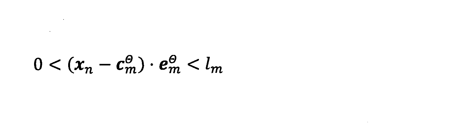
ここで、lmは、キャリブレーション情報に含まれる長さパラメータである(即ち長さ算出部128により導出される部位mの長さパラメータlm)。
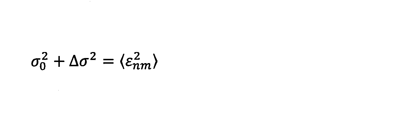
微小変化算出部156は、変形パラメータθarの微小変化Δθを算出する。ここで、尤度関数の最大化問題は、分散σ2と同様に、以下の通り、線形近似により解を導出できる。即ち、第2時点は、第1時点よりも微小時間だけ後であるので、第2時点での点群データxnは、第1時点での点群データxnから大きく変化しないと期待される。このため、第2時点での変形パラメータθarは、第1時点での変形パラメータθarから大きく変化しないと期待される。従って、第2時点での変形パラメータθarは、第1時点での変形パラメータθarからの微小変化Δθで表されるものとする。

よって、変形パラメータθarの微小変化Δθは、表面残差εnm、及び、表面残差の微分ε'nm(数40参照)を用いて、以下のとおりである。
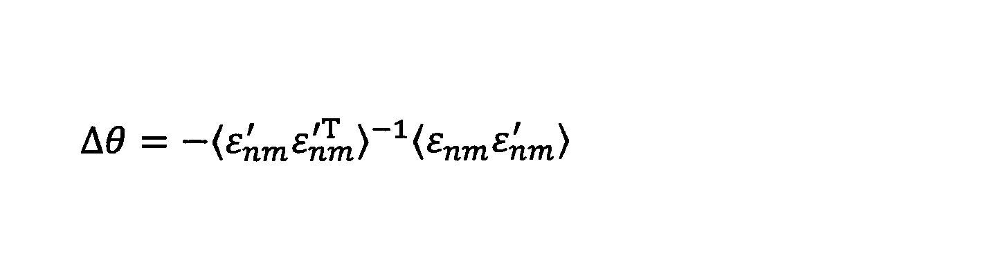
尚、具体的な微小変化Δθの算出方法は、次のパラメータ更新部158の説明に関連して後述する。


ここで、Δck Θ及びΔek Θは、機構モデルの順運動学に基き、以下のように導出可能である。

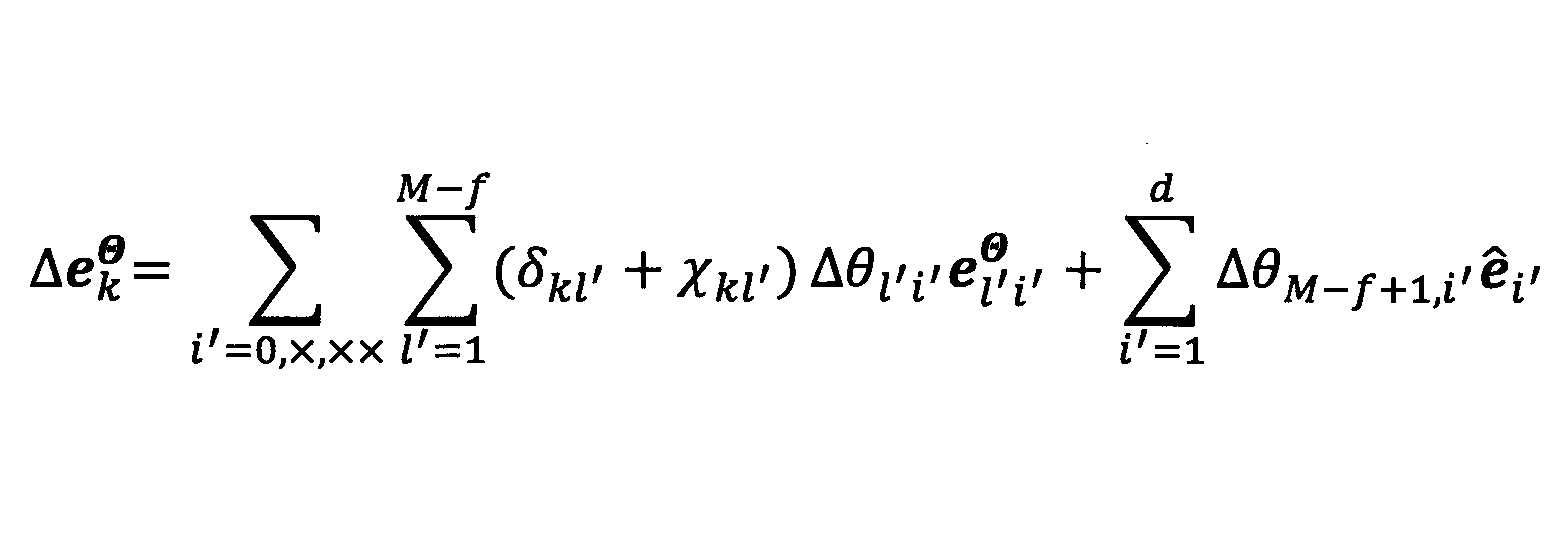
ここで、Δθl'i'、ΔθM-f+1,i'、及びΔθM-f+2,i'は、微小変化Δθの各要素である。Δθl'i'は、部位l'(l'=1,2、・・・、M-f)の関節回転を表し、ΔθM-f+1,i'は、対象者Sの重心の回転を表し、ΔθM-f+2,i'は、対象者Sの重心の並進を表す。i'は、回転の3自由度を表し、i'=0、X,XXである。dは空間次元であり、d=3である。また、fは、可動しない関節数である。可動しない関節とは、例えば骨盤部(図4の部位b14、b15参照)に係る関節(図4の関節a0参照)である。
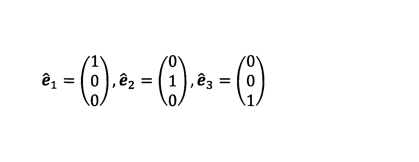

また、δkl'は、クロネッカーのデルタであり、上述と同様である。また、χkl'は、部位k(k=1,2、・・・、15)と部位l'(l'=1,2、・・・、13)との祖先・子孫関係を表すパラメータであり、例えば、図10に示すとおりである。図10における部位の番号は、図11に示すとおりである。例えば、部位m=部位6でありかつ部位l'=部位5であるとき、χ56=1である。これは、部位5が部位6の祖先側にあるためである。尚、図10及び図11に示す例では、可動しない骨盤部の番号が最後の2つ"14"及び"15"とされかつが列から除外されている。尚、行と列は、同一の番号が同一の部位を指す。
21 距離画像センサ
100 対象物認識装置
110 データ入力部
120 1シーン骨格認識部
122 クラスタリング部
124 EMアルゴリズム部
126 モデル最適化部
128 長さ算出部
130 部位認識部
132 骨格整形部
134 キャリブレーション情報生成部
140 幾何モデルデータベース
142 キャリブレーション情報記憶部
150 微小フィッティング処理部
151 表面残差算出部
152 事後分布算出部
154 有限長処理部
155 分散更新部
156 微小変化算出部
158 パラメータ更新部
160 出力部
Claims (21)
- 3次元の位置情報を得るセンサから、複数の関節を有する対象物の表面に係る点群データを取得し、
前記対象物の複数の部位のそれぞれの位置及び軸方向を表す第1パラメータであって、第1時点での第1パラメータを導出又は取得し、
前記第1時点より後の第2時点での前記点群データと、前記第1時点での前記第1パラメータと、軸を有する幾何モデルとに基づいて、前記第2時点での前記第1パラメータを導出することを含む、コンピュータにより実行される対象物認識方法。 - 前記点群データの取得は、周期毎に実行され、
前記第2時点は、前記第1時点に係る周期の次の周期を含む、請求項1に記載の対象物認識方法。 - 前記第1時点での前記第1パラメータの導出は、前記第1時点での前記点群データに、前記幾何モデルを複数の個所で別々に当てはめ、前記第1時点での前記点群データに当てはめる複数の前記幾何モデルのそれぞれの位置及び軸方向に基づいて、前記第1時点での前記第1パラメータを導出する当てはめ処理を含み、
前記第2時点での前記第1パラメータの導出は、前記第2時点での前記点群データに当てはまる複数の前記幾何モデルのそれぞれの位置及び軸方向を、前記第2時点での前記第1パラメータを導出することを含む、請求項1又は2に記載の対象物認識方法。 - 前記当てはめ処理は、前記点群データに含まれるノイズを一様分布でモデル化することを含む、請求項3に記載の対象物認識方法。
- 前記幾何モデルは、円柱、円錐、台形柱、楕円柱、楕円錐、及び台形楕円柱のうちの少なくともいずれか1つに係り、
前記第2時点での前記第1パラメータの導出は、前記第1時点での前記第1パラメータの導出に用いた種類の複数の前記幾何モデルに基づく、請求項3又は4に記載の対象物認識方法。 - 前記第2時点での前記第1パラメータの導出は、前記当てはめ処理によって第1所定基準を満たす前記第1パラメータが得られた後に実行され、
前記当てはめ処理は、前記第1所定基準を満たす前記第1パラメータが得られるまで周期毎に繰り返される、請求項3~5のうちのいずれか1項に記載の対象物認識方法。 - 前記当てはめ処理は、前記第1時点での前記点群データに基づく第1事後分布を算出することを含み、
前記第1所定基準は、前記複数の部位の数が所定数以上であり、かつ、前記複数の部位のそれぞれに係る前記第1事後分布のデータ和が第1所定値以上である場合に満たされる、請求項6に記載の対象物認識方法。 - 前記第2時点での前記第1パラメータの導出結果が第2所定基準を満たすか否かを判定することを更に含み、
前記第2時点での前記第1パラメータの導出結果が前記第2所定基準を満たさない場合は、新たな前記第1時点での前記第1パラメータの導出からやり直すことを含む、請求項6又は7に記載の対象物認識方法。 - 前記第2時点での前記点群データに基づく第2事後分布を算出することを含み、
前記複数の部位は、複数の前記幾何モデルに対応付けられる複数の第1部位と、前記幾何モデルに対応付けられない複数の第2部位とを含み、
前記第2所定基準は、前記複数の第1部位のそれぞれに係る前記第2事後分布のデータ和の合計が第2所定値以上である場合に満たされる、請求項8に記載の対象物認識方法。 - 前記第2事後分布の算出は、前記複数の第1部位のそれぞれごとに、前記第2時点での前記点群データのうちの、前記第1部位に対応付けられる前記幾何モデルの軸方向の中心からの軸方向の距離が所定距離以上のデータに対し、前記第2事後分布を0にすることを含む、請求項9に記載の対象物認識方法。
- 前記対象物は、人、又は、人型のロボットであり、
前記複数の第2部位は、前記対象物の腕部の根本の関節と、前記対象物の胴部における頭部側の関節とを結ぶ部位と、前記対象物の脚部の根本の関節と、前記対象物の胴部における前記脚部側の関節とを結ぶ部位を含む、請求項10に記載の対象物認識方法。 - 前記第2時点での前記第1パラメータの導出結果が前記第2所定基準を満たす場合は、該第2時点での前記第2時点での前記第1パラメータの導出結果と、該第2時点に係る周期の次の周期の前記点群データとに基づいて、新たな前記第2時点での前記第1パラメータを導出することを更に含む、請求項8~11のうちのいずれか1項に記載の対象物認識方法。
- 前記第2時点での前記第1パラメータの導出は、前記複数の部位のそれぞれごとに、位置及び軸方向のそれぞれの変化であって、前記第1時点からの変化を表す第2パラメータを導出することを含む、請求項12に記載の対象物認識方法。
- 前記第2パラメータの算出は、前記対象物の関節に対応付け可能な複数の関節を有する機構モデルを用いた順運動学に基く計算処理を含む、請求項13に記載の対象物認識方法。
- 前記計算処理は、前記対象物の重心の並進、回転、及び前記複数の関節のそれぞれの回転を、微小変化するものとして扱うことを伴う、請求項14に記載の対象物認識方法。
- 前記複数の部位は、可動部位と、非可動部位とを含み、
前記機構モデルは、前記複数の関節のうちの前記可動部位に係る各関節に3軸まわりの回転自由度を与えるモデルである、請求項15に記載の対象物認識方法。 - 前記第2パラメータの算出は、前記計算処理のうちの、前記複数の関節のうちの前記非可動部位間の関節に係る計算部分を省略することを含む、請求項16に記載の対象物認識方法。
- 前記第2パラメータの算出は、前記計算処理のうちの、前記複数の部位のうちの軸対称の幾何モデルに対応付けられる部位に係る計算部分であって、軸まわりの回転に係る計算部分を省略することを含む、請求項16に記載の対象物認識方法。
- 3次元の位置情報を得るセンサから、複数の関節を有する対象物の表面に係る点群データを取得する取得部と、
前記対象物の複数の部位のそれぞれの位置及び軸方向を表す第1パラメータであって、第1時点での第1パラメータを導出又は取得するパラメータ導出/取得部と、
前記第1時点より後の第2時点での前記点群データと、前記第1時点での前記第1パラメータと、軸を有する幾何モデルとに基づいて、前記第2時点での前記第1パラメータを導出する導出処理部とを含む、対象物認識装置。 - 3次元の位置情報を得るセンサと、
前記センサから、複数の関節を有する対象物の表面に係る点群データを取得する取得部と、
前記対象物の複数の部位のそれぞれの位置及び軸方向を表す第1パラメータであって、第1時点での第1パラメータを導出又は取得するパラメータ導出/取得部と、
前記第1時点より後の第2時点での前記点群データと、前記第1時点での前記第1パラメータと、軸を有する幾何モデルとに基づいて、前記第2時点での前記第1パラメータを導出する導出処理部とを含む、対象物認識システム。 - 3次元の位置情報を得るセンサから、複数の関節を有する対象物の表面に係る点群データを取得し、
前記対象物の複数の部位のそれぞれの位置及び軸方向を表す第1パラメータであって、第1時点での第1パラメータを導出又は取得し、
前記第1時点より後の第2時点での前記点群データと、前記第1時点での前記第1パラメータと、軸を有する幾何モデルとに基づいて、前記第2時点での前記第1パラメータを導出する
処理をコンピュータに実行させる対象物認識プログラム。
Priority Applications (5)
| Application Number | Priority Date | Filing Date | Title |
|---|---|---|---|
| EP17909083.2A EP3624059A4 (en) | 2017-05-10 | 2017-05-10 | TARGET OBJECT DETECTION METHOD, DEVICE, SYSTEM AND PROGRAM |
| JP2019516792A JP6996557B2 (ja) | 2017-05-10 | 2017-05-10 | 対象物認識方法、装置、システム、プログラム |
| PCT/JP2017/017695 WO2018207282A1 (ja) | 2017-05-10 | 2017-05-10 | 対象物認識方法、装置、システム、プログラム |
| CN201780090522.7A CN110603570B (zh) | 2017-05-10 | 2017-05-10 | 对象物识别方法、装置、系统、程序 |
| US16/676,527 US11126831B2 (en) | 2017-05-10 | 2019-11-07 | Object recognition method, device, system, and program |
Applications Claiming Priority (1)
| Application Number | Priority Date | Filing Date | Title |
|---|---|---|---|
| PCT/JP2017/017695 WO2018207282A1 (ja) | 2017-05-10 | 2017-05-10 | 対象物認識方法、装置、システム、プログラム |
Related Child Applications (1)
| Application Number | Title | Priority Date | Filing Date |
|---|---|---|---|
| US16/676,527 Continuation US11126831B2 (en) | 2017-05-10 | 2019-11-07 | Object recognition method, device, system, and program |
Publications (1)
| Publication Number | Publication Date |
|---|---|
| WO2018207282A1 true WO2018207282A1 (ja) | 2018-11-15 |
Family
ID=64104549
Family Applications (1)
| Application Number | Title | Priority Date | Filing Date |
|---|---|---|---|
| PCT/JP2017/017695 Ceased WO2018207282A1 (ja) | 2017-05-10 | 2017-05-10 | 対象物認識方法、装置、システム、プログラム |
Country Status (5)
| Country | Link |
|---|---|
| US (1) | US11126831B2 (ja) |
| EP (1) | EP3624059A4 (ja) |
| JP (1) | JP6996557B2 (ja) |
| CN (1) | CN110603570B (ja) |
| WO (1) | WO2018207282A1 (ja) |
Cited By (3)
| Publication number | Priority date | Publication date | Assignee | Title |
|---|---|---|---|---|
| CN113436223A (zh) * | 2021-07-14 | 2021-09-24 | 北京市测绘设计研究院 | 点云数据的分割方法、装置、计算机设备和存储介质 |
| JP2022057885A (ja) * | 2020-09-30 | 2022-04-11 | アースアイズ株式会社 | 撮影システム、及び、撮影方法 |
| JP2023003929A (ja) * | 2021-06-25 | 2023-01-17 | 富士通株式会社 | 骨格認識方法、骨格認識プログラム、および体操採点支援システム |
Families Citing this family (6)
| Publication number | Priority date | Publication date | Assignee | Title |
|---|---|---|---|---|
| EP3624059A4 (en) | 2017-05-10 | 2020-05-27 | Fujitsu Limited | TARGET OBJECT DETECTION METHOD, DEVICE, SYSTEM AND PROGRAM |
| EP3425591B1 (en) * | 2017-07-07 | 2021-01-13 | Tata Consultancy Services Limited | System and method for tracking body joints |
| JP6947215B2 (ja) | 2017-08-07 | 2021-10-13 | 富士通株式会社 | 情報処理装置、モデルデータ作成プログラム、モデルデータ作成方法 |
| US10620713B1 (en) * | 2019-06-05 | 2020-04-14 | NEX Team Inc. | Methods and systems for touchless control with a mobile device |
| EP3825730A1 (en) * | 2019-11-21 | 2021-05-26 | Bentley Systems, Incorporated | Assigning each point of a point cloud to a scanner position of a plurality of different scanner positions in a point cloud |
| CN114117652B (zh) * | 2020-08-31 | 2024-09-10 | 重庆大学 | 基于工业ct图像的工件内部裂纹提取和扩展分析的方法 |
Citations (2)
| Publication number | Priority date | Publication date | Assignee | Title |
|---|---|---|---|---|
| JP2010015472A (ja) * | 2008-07-07 | 2010-01-21 | Nippon Telegr & Teleph Corp <Ntt> | 歩行者性別判定装置、歩行者性別判定方法、歩行者性別判定プログラムおよびその記録媒体 |
| JP2015102913A (ja) * | 2013-11-21 | 2015-06-04 | キヤノン株式会社 | 姿勢推定装置及び姿勢推定方法 |
Family Cites Families (27)
| Publication number | Priority date | Publication date | Assignee | Title |
|---|---|---|---|---|
| JPH10149445A (ja) | 1996-11-19 | 1998-06-02 | Image Joho Kagaku Kenkyusho | 身体動作解析可視化装置 |
| JP2006302133A (ja) * | 2005-04-22 | 2006-11-02 | Toyota Motor Corp | 情報処理装置、情報処理方法、及びこれを用いた画像情報処理装置、画像情報処理方法 |
| KR100951890B1 (ko) * | 2008-01-25 | 2010-04-12 | 성균관대학교산학협력단 | 상황 모니터링을 적용한 실시간 물체 인식 및 자세 추정 방법 |
| US9135502B2 (en) | 2009-05-11 | 2015-09-15 | Universitat Zu Lubeck | Method for the real-time-capable, computer-assisted analysis of an image sequence containing a variable pose |
| US8542252B2 (en) * | 2009-05-29 | 2013-09-24 | Microsoft Corporation | Target digitization, extraction, and tracking |
| JP5297403B2 (ja) | 2010-02-26 | 2013-09-25 | キヤノン株式会社 | 位置姿勢計測装置、位置姿勢計測方法、プログラムおよび記憶媒体 |
| EP2383696A1 (en) | 2010-04-30 | 2011-11-02 | LiberoVision AG | Method for estimating a pose of an articulated object model |
| US20130144135A1 (en) * | 2011-08-02 | 2013-06-06 | Mohamed R. Mahfouz | Method and apparatus for three dimensional reconstruction of a joint using ultrasound |
| EP2710557B1 (en) | 2011-05-16 | 2020-04-29 | Max-Planck-Gesellschaft zur Förderung der Wissenschaften e.V. | Fast articulated motion tracking |
| US9367770B2 (en) * | 2011-08-30 | 2016-06-14 | Digimarc Corporation | Methods and arrangements for identifying objects |
| WO2013033442A1 (en) * | 2011-08-30 | 2013-03-07 | Digimarc Corporation | Methods and arrangements for identifying objects |
| JP2013115380A (ja) * | 2011-11-30 | 2013-06-10 | Panasonic Corp | 部品実装装置および部品実装方法 |
| US9235928B2 (en) | 2012-01-24 | 2016-01-12 | University Of Southern California | 3D body modeling, from a single or multiple 3D cameras, in the presence of motion |
| US20130335528A1 (en) * | 2012-05-15 | 2013-12-19 | Board Of Regents Of The University Of Texas System | Imaging device capable of producing three dimensional representations and methods of use |
| EP2674913B1 (en) * | 2012-06-14 | 2014-07-23 | Softkinetic Software | Three-dimensional object modelling fitting & tracking. |
| US9541997B2 (en) * | 2012-07-27 | 2017-01-10 | Nec Solution Innovators, Ltd. | Three-dimensional user interface apparatus and three-dimensional operation method |
| US20150193977A1 (en) * | 2012-08-31 | 2015-07-09 | Google Inc. | Self-Describing Three-Dimensional (3D) Object Recognition and Control Descriptors for Augmented Reality Interfaces |
| JP2015170907A (ja) * | 2014-03-05 | 2015-09-28 | キヤノン株式会社 | スキャナシステム、スキャナシステムのデータ処理方法、及びプログラム |
| US9928412B2 (en) | 2014-10-17 | 2018-03-27 | Ebay Inc. | Method, medium, and system for fast 3D model fitting and anthropometrics |
| JP2016103137A (ja) * | 2014-11-28 | 2016-06-02 | キヤノン株式会社 | ユーザインタフェース装置、画像処理装置及び制御用プログラム |
| US9747717B2 (en) * | 2015-05-13 | 2017-08-29 | Intel Corporation | Iterative closest point technique based on a solution of inverse kinematics problem |
| JP2017036998A (ja) * | 2015-08-10 | 2017-02-16 | 株式会社東芝 | 色情報決定装置および画像生成装置 |
| JP2017073039A (ja) * | 2015-10-08 | 2017-04-13 | キヤノン株式会社 | 物体識別装置、物体識別方法及びプログラム |
| US10186081B2 (en) | 2015-12-29 | 2019-01-22 | Microsoft Technology Licensing, Llc | Tracking rigged smooth-surface models of articulated objects |
| US9898858B2 (en) | 2016-05-18 | 2018-02-20 | Siemens Healthcare Gmbh | Human body representation with non-rigid parts in an imaging system |
| EP3249921A1 (en) * | 2016-05-24 | 2017-11-29 | Thomson Licensing | Method, apparatus and stream for immersive video format |
| EP3624059A4 (en) | 2017-05-10 | 2020-05-27 | Fujitsu Limited | TARGET OBJECT DETECTION METHOD, DEVICE, SYSTEM AND PROGRAM |
-
2017
- 2017-05-10 EP EP17909083.2A patent/EP3624059A4/en not_active Withdrawn
- 2017-05-10 WO PCT/JP2017/017695 patent/WO2018207282A1/ja not_active Ceased
- 2017-05-10 JP JP2019516792A patent/JP6996557B2/ja not_active Expired - Fee Related
- 2017-05-10 CN CN201780090522.7A patent/CN110603570B/zh not_active Expired - Fee Related
-
2019
- 2019-11-07 US US16/676,527 patent/US11126831B2/en not_active Expired - Fee Related
Patent Citations (2)
| Publication number | Priority date | Publication date | Assignee | Title |
|---|---|---|---|---|
| JP2010015472A (ja) * | 2008-07-07 | 2010-01-21 | Nippon Telegr & Teleph Corp <Ntt> | 歩行者性別判定装置、歩行者性別判定方法、歩行者性別判定プログラムおよびその記録媒体 |
| JP2015102913A (ja) * | 2013-11-21 | 2015-06-04 | キヤノン株式会社 | 姿勢推定装置及び姿勢推定方法 |
Non-Patent Citations (3)
| Title |
|---|
| ARATA MIYAMOTO ET AL.: "Human Pose Estimation from 3D Object Skeleton using Articulated Cylindrical Human Model", IPSJ SIG NOTES, vol. 2006, no. 51, 19 May 2006 (2006-05-19), pages 137 - 144, XP055639781 * |
| EIICHI HORIUCHI: "Hemi-form Geometric Models for Single-scan 3D Point Clouds", JOURNAL OF THE ROBOTICS SOCIETY OF JAPAN, vol. 32, no. 8, 15 October 2014 (2014-10-15), pages 721 - 730, XP055545372 * |
| See also references of EP3624059A4 * |
Cited By (4)
| Publication number | Priority date | Publication date | Assignee | Title |
|---|---|---|---|---|
| JP2022057885A (ja) * | 2020-09-30 | 2022-04-11 | アースアイズ株式会社 | 撮影システム、及び、撮影方法 |
| JP2023003929A (ja) * | 2021-06-25 | 2023-01-17 | 富士通株式会社 | 骨格認識方法、骨格認識プログラム、および体操採点支援システム |
| CN113436223A (zh) * | 2021-07-14 | 2021-09-24 | 北京市测绘设计研究院 | 点云数据的分割方法、装置、计算机设备和存储介质 |
| CN113436223B (zh) * | 2021-07-14 | 2022-05-24 | 北京市测绘设计研究院 | 点云数据的分割方法、装置、计算机设备和存储介质 |
Also Published As
| Publication number | Publication date |
|---|---|
| EP3624059A4 (en) | 2020-05-27 |
| US11126831B2 (en) | 2021-09-21 |
| JP6996557B2 (ja) | 2022-02-21 |
| JPWO2018207282A1 (ja) | 2020-03-12 |
| US20200074161A1 (en) | 2020-03-05 |
| CN110603570A (zh) | 2019-12-20 |
| CN110603570B (zh) | 2023-08-04 |
| EP3624059A1 (en) | 2020-03-18 |
Similar Documents
| Publication | Publication Date | Title |
|---|---|---|
| JP6996557B2 (ja) | 対象物認識方法、装置、システム、プログラム | |
| KR101333836B1 (ko) | 에이에이엠 및 추정된 깊이 정보를 이용하는 3차원 얼굴 포즈 및 표정 변화 추정 방법 | |
| JP6947215B2 (ja) | 情報処理装置、モデルデータ作成プログラム、モデルデータ作成方法 | |
| JP4950787B2 (ja) | 画像処理装置及びその方法 | |
| CN107122705B (zh) | 基于三维人脸模型的人脸关键点检测方法 | |
| US10189162B2 (en) | Model generation apparatus, information processing apparatus, model generation method, and information processing method | |
| WO2021084677A1 (ja) | 画像処理装置、画像処理方法及び画像処理プログラムが格納された非一時的なコンピュータ可読媒体 | |
| KR101700377B1 (ko) | 아바타 생성을 위한 처리 장치 및 방법 | |
| JP6465027B2 (ja) | 特徴点位置推定装置、特徴点位置推定方法および特徴点位置推定プログラム | |
| CN114422832A (zh) | 主播虚拟形象生成方法及装置 | |
| JP6920246B2 (ja) | 行動認識装置、モデル構築装置及びプログラム | |
| JP2016099982A (ja) | 行動認識装置、行動学習装置、方法、及びプログラム | |
| WO2005111936A1 (ja) | パラメタ推定方法、パラメタ推定装置および照合方法 | |
| JP2012128661A (ja) | 情報処理装置、情報処理方法及びプログラム | |
| JP7464512B2 (ja) | 三次元人物姿勢推定装置、方法およびプログラム | |
| JP4535096B2 (ja) | 平面抽出方法、その装置、そのプログラム、その記録媒体及び撮像装置 | |
| KR102948410B1 (ko) | 골프 스윙에 관한 정보를 추정하기 위한 방법, 디바이스 및 비일시성의 컴퓨터 판독 가능한 기록 매체 | |
| JP4765075B2 (ja) | ステレオ画像を利用した物体の位置および姿勢認識システムならびに物体の位置および姿勢認識方法を実行するプログラム | |
| WO2021166174A1 (ja) | 被写体別特徴点分離装置、被写体別特徴点分離方法及びコンピュータプログラム | |
| WO2018207292A1 (ja) | 対象物認識方法、装置、システム、プログラム | |
| JP5872401B2 (ja) | 領域分割装置 | |
| CN111612912B (zh) | 一种基于Kinect 2相机面部轮廓点云模型的快速三维重构及优化方法 | |
| CN108694348B (zh) | 一种基于自然特征的跟踪注册方法及装置 | |
| JPH09198504A (ja) | 姿勢検出装置 | |
| JP6260146B2 (ja) | 形状状態推定装置、形状モデル生成装置、及びプログラム |
Legal Events
| Date | Code | Title | Description |
|---|---|---|---|
| 121 | Ep: the epo has been informed by wipo that ep was designated in this application |
Ref document number: 17909083 Country of ref document: EP Kind code of ref document: A1 |
|
| ENP | Entry into the national phase |
Ref document number: 2019516792 Country of ref document: JP Kind code of ref document: A |
|
| NENP | Non-entry into the national phase |
Ref country code: DE |
|
| ENP | Entry into the national phase |
Ref document number: 2017909083 Country of ref document: EP Effective date: 20191210 |
|
| WWW | Wipo information: withdrawn in national office |
Ref document number: 2017909083 Country of ref document: EP |