WO2018207397A1 - 切粉回収装置 - Google Patents
切粉回収装置 Download PDFInfo
- Publication number
- WO2018207397A1 WO2018207397A1 PCT/JP2017/045046 JP2017045046W WO2018207397A1 WO 2018207397 A1 WO2018207397 A1 WO 2018207397A1 JP 2017045046 W JP2017045046 W JP 2017045046W WO 2018207397 A1 WO2018207397 A1 WO 2018207397A1
- Authority
- WO
- WIPO (PCT)
- Prior art keywords
- chip
- cover case
- side wall
- air
- base frame
- Prior art date
- Legal status (The legal status is an assumption and is not a legal conclusion. Google has not performed a legal analysis and makes no representation as to the accuracy of the status listed.)
- Ceased
Links
Images


Classifications
-
- B—PERFORMING OPERATIONS; TRANSPORTING
- B23—MACHINE TOOLS; METAL-WORKING NOT OTHERWISE PROVIDED FOR
- B23Q—DETAILS, COMPONENTS, OR ACCESSORIES FOR MACHINE TOOLS, e.g. ARRANGEMENTS FOR COPYING OR CONTROLLING; MACHINE TOOLS IN GENERAL CHARACTERISED BY THE CONSTRUCTION OF PARTICULAR DETAILS OR COMPONENTS; COMBINATIONS OR ASSOCIATIONS OF METAL-WORKING MACHINES, NOT DIRECTED TO A PARTICULAR RESULT
- B23Q11/00—Accessories fitted to machine tools for keeping tools or parts of the machine in good working condition or for cooling work; Safety devices specially combined with or arranged in, or specially adapted for use in connection with, machine tools
- B23Q11/0042—Devices for removing chips
- B23Q11/0046—Devices for removing chips by sucking
-
- B—PERFORMING OPERATIONS; TRANSPORTING
- B23—MACHINE TOOLS; METAL-WORKING NOT OTHERWISE PROVIDED FOR
- B23K—SOLDERING OR UNSOLDERING; WELDING; CLADDING OR PLATING BY SOLDERING OR WELDING; CUTTING BY APPLYING HEAT LOCALLY, e.g. FLAME CUTTING; WORKING BY LASER BEAM
- B23K11/00—Resistance welding; Severing by resistance heating
- B23K11/30—Features relating to electrodes
- B23K11/3063—Electrode maintenance, e.g. cleaning, grinding
-
- B—PERFORMING OPERATIONS; TRANSPORTING
- B23—MACHINE TOOLS; METAL-WORKING NOT OTHERWISE PROVIDED FOR
- B23Q—DETAILS, COMPONENTS, OR ACCESSORIES FOR MACHINE TOOLS, e.g. ARRANGEMENTS FOR COPYING OR CONTROLLING; MACHINE TOOLS IN GENERAL CHARACTERISED BY THE CONSTRUCTION OF PARTICULAR DETAILS OR COMPONENTS; COMBINATIONS OR ASSOCIATIONS OF METAL-WORKING MACHINES, NOT DIRECTED TO A PARTICULAR RESULT
- B23Q11/00—Accessories fitted to machine tools for keeping tools or parts of the machine in good working condition or for cooling work; Safety devices specially combined with or arranged in, or specially adapted for use in connection with, machine tools
Definitions
- the present invention relates to a chip collection device that collects chips generated by a cutting operation when the tip of an electrode tip for spot welding is cut with a chip dresser.
- chips generated when cutting the tip of the electrode tip with a tip dresser increase the load on the drive unit when attached to the drive unit of the device, and in the worst case, the device may break down. It is desirable to collect it immediately after it occurs.
- a chip collection device disclosed in Patent Document 1 includes a cover case fixed so as to cover a cutting edge portion of a chip dresser, and the cover case has a plate shape extending in the horizontal direction.
- An air suction tool that sucks air from the inside of the cover case and an air introduction unit that introduces compressed air into the cover case are connected to the cover case.
- the air suction tool is connected to one end of the cover case in the horizontal direction, while the air introduction unit is connected to the other end of the cover case in the horizontal direction, and is a turbulent air flow caused by compressed air introduced into the cover case by the air introduction unit.
- the cover case has a wide shape in the horizontal direction so that the attachment portion of the air introduction unit to the cover case does not interfere with the chip dresser. Therefore, there is a problem that the entire apparatus is enlarged and a large installation space is required.
- the suction force in the area far from the air suction tool inside the cover case will be weakened, especially the area farthest from the air suction tool inside the cover case. In this case, the chip recovery capability may be reduced.
- the present invention has been made in view of such a point, and an object of the present invention is to provide a chip collecting apparatus having a compact shape and high chip collecting ability.
- the present invention is characterized in that in the cover case, the air suction means and the air introduction hole are provided to face each other at a close position, and the shape of the air introduction hole is devised. To do.
- the following solution was taken for a chip collecting device capable of collecting chips generated when cutting the tip of the electrode tip for spot welding with the cutting edge of the chip dresser.
- a box-shaped cover case having first and second rectangular plate-shaped side walls fixed to the chip dresser so as to cover the cutting edge portion and opposed in the horizontal direction, and the first An air suction means connected to the side wall for sucking air inside the cover case and an air suction means formed on the second side wall for introducing air into the cover case from the outside during the air suction operation by the air suction means.
- the air introduction hole has a shape extending in an L shape along a corner of the lower portion of the second side wall.
- a pair of the air introduction holes are formed at both corners of the lower part of the second side wall.
- the second side wall includes a base frame having a rectangular frame shape, and a main body plate assembled to the inside of the base frame.
- the introduction hole is formed between the base frame and the main body plate.
- the main body plate includes an inner plate positioned on the inner surface side of the base frame and an outer plate positioned on the outer surface side of the base frame, and the second side wall is The base plate is configured to be assembled by connecting the inner plate and the outer plate in a state where the inner peripheral portion of the base frame is sandwiched between the outer peripheral portion of the inner plate and the outer peripheral portion of the outer plate.
- the cover case since it is not necessary to attach the air introduction unit as in Patent Document 1 to the cover case, the cover case can be made short in the horizontal direction. Therefore, since the whole apparatus becomes compact, the space around the installation can be effectively used. Further, when the air inside the cover case is sucked by the air suction means, the inside of the cover case becomes negative pressure, and the air is introduced from the outside to the inside of the cover case through the air introduction hole. At this time, since the air introduction hole is inclined so as to be directed to at least one of the inner side surface and the bottom side surface of the cover case, the air that has passed through the air introduction hole is folded back at least one of the inner side surface and the bottom side surface of the cover case.
- the chips located inside the cover case can be reliably discharged to the outside of the cover case without accumulating on the inner bottom surface, and a chip collecting apparatus with high chip collecting ability can be obtained.
- the air introduced from the air introduction hole is folded back to the inner bottom surface and the inner side surface of the cover case so as to vortex. Therefore, the airflow inside the cover case is easily disturbed and the chips inside the cover case are likely to float, so that the chips can be efficiently discharged to the outside of the cover case.
- the air passing through the air introduction hole is intensively directed to the corners where the chips are particularly likely to accumulate inside the cover case, so that the chips accumulated in the corners inside the cover case can be surely collected. It can be discharged outside the cover case.
- the air introduction hole of the present invention is formed by combining two parts, there is no need to perform complicated hole machining on the part in order to form the air introduction hole, and the device is easy to manufacture. it can.
- the inner plate and the outer plate when the inner plate and the outer plate are connected and integrated, the inner plate and the outer plate are also integrated with the base frame. Therefore, additional parts for assembling the inner plate and the outer plate to the base frame are required. And a low-cost device with few parts.
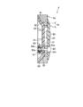
- FIG. 2 is a cross-sectional view taken along line II-II in FIG.
- FIG. 3 is a view taken in the direction of arrow III in FIG. 2.
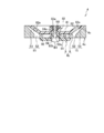
- FIG. 4 is a cross-sectional view taken along line IV-IV in FIG. 3.
- FIG. 5 is a sectional view taken along line VV in FIG. 3.
- FIG. 4 is a cross-sectional view taken along line VI-VI in FIG. 3.
- FIG. 1 shows a chip dresser 10 equipped with a chip collection device 1 according to an embodiment of the present invention.
- the chip collection device 1 collects the chips M ⁇ b> 1 that are generated when the tip dressers 10 of the pair of electrode tips 11 attached to the welding gun for spot welding are cut by the chip dresser 10. belongs to.
- the chip dresser 10 includes a motor case portion 10a having a substantially cylindrical shape whose cylinder center line direction is directed in the vertical direction, and a front end of the motor case portion 10a from the upper end of the motor case portion 10a.
- a pair of through holes 10d having a circular shape facing each other are formed on the upper surface and the lower surface of the central portion of the extension side of the gear case portion 10b.
- a ring-shaped output gear 12 is rotatably mounted around a rotation axis C1 extending in the vertical direction via a pair of upper and lower bearings 14.
- a mounting hole 12a penetrating vertically is provided, and a metal cutting cutter 13 for cutting the tip 11a of the electrode tip 11 is mounted in the mounting hole 12a.
- the cutting cutter 13 is provided with a pair of curved surface portions 13 a that open upward and downward, and each curved surface portion 13 a is provided with a cutting blade portion 13 b that extends so as to correspond to the radial direction of the tip of the electrode tip 11. ing.
- the box-shaped cover case 2 is fixed to the lower surface of the gear case portion 10b so as to cover the cutting edge portion 13b of the cutting cutter 13 via a plate-shaped bracket 2a having a ring shape.
- the plate-like bracket 2a can change the mounting posture of the cover case 2 around the rotation axis C1 when the cover case 2 is attached to the gear case portion 10b.
- the cover case 2 includes a first side wall 3 and a second side wall 4 each having a rectangular plate shape facing each other in the horizontal direction orthogonal to the extending direction of the gear case portion 10b.
- each resin sheet material 5 extends in a straight line downward from a position near the upper end in the middle in the horizontal direction.
- a slit 5a opening at the lower end is formed.
- a rectangular bottom wall 6 is provided between the lower end edge of the first side wall 3 and the lower end edge of the second side wall 4, and the electrode tip 11 can pass through the central portion of the bottom wall 6.
- a chip passing portion 6a is formed.
- a pair of cover brushes 61 are attached to the bottom surface of the bottom wall 6 so as to face each other in the horizontal direction orthogonal to the extending direction of the gear case portion 10b.
- the cover brush 61 includes a base plate 61a extending along the extending direction of the gear case portion 10b, and a resin hair bundle 61b planted on the base plate 61a.
- the hair bundles 61b approach each other.
- the bottom wall 6 extends to the middle.
- a mounting hole 3a penetrating in the horizontal direction is formed in the first side wall 3, and an air suction tool 7 (air suction means) is connected to the mounting hole 3a.
- the air suction tool 7 includes a cylindrical body 71 having a cylindrical center line extending in a horizontal direction perpendicular to the extending direction of the gear case portion 10b.
- the cylindrical body 71 includes a first cylindrical member 72 and a second cylindrical member 72 that are open at both ends.
- a cylindrical member 73 is provided.
- the first groove groove 72a extending around the cylinder center line is formed on the outer peripheral surface on the one end side of the first tube member 72.
- the first groove groove 72a has a wide groove width and a shallow bottom. It has a shape.
- a male screw portion 72b is formed on the outer peripheral surface of the middle portion of the first cylindrical member 72 so as to be continuous with the first concave groove portion 72a.
- An annular projecting surface portion 72c is formed on the inner peripheral surface on the one end side of the first cylindrical member 72 so as to project inward in the radial direction of the cylindrical body 71 and extend around the cylinder center line.
- the projecting surface 72d of the annular projecting surface portion 72c has a shape extending from the one end surface of the first cylindrical member 72 to the radially inner side of the cylindrical body 71 and gradually curving toward the other end side of the first cylindrical member 72. Yes.
- a blowing side air guide surface 72e that is continuous with the overhanging surface 72d is formed in a portion from the midway part to the other end side of the inner peripheral surface of the first cylindrical member 72, and the blowing side air guide surface 72e
- the taper shape gradually increases in diameter as the distance from the projecting surface 72d increases.
- a tapered surface portion 73a that gradually decreases in diameter toward the one end is formed.
- annular mounting surface portion 73b that is recessed in a step shape and extends along the periphery of the other end opening is formed.
- a male screw portion (not shown) is formed on the surface of the annular mounting surface portion 73b, and the male screw portion is screwed into a female screw portion (not shown) formed on the inner peripheral surface of the mounting hole 3a in the first side wall 3.
- the second cylinder member 73 is attached to the first side wall 3 by combining them.
- An annular second groove groove portion 73c extending around the cylinder center line is formed on the inner peripheral surface of the second tube member 73, and the second groove groove portion 73c has a wide groove width and a shallow bottom. It has a shape.
- the second concave groove 73c includes a belt-like bottom surface 73h that extends annularly around the cylinder center line, a first annular surface 73i that extends in a direction perpendicular to the tube center line from one edge of the belt-like bottom surface 73h, and the belt-like bottom surface.
- the second annular surface 73j extends in the direction orthogonal to the cylinder center line from the other edge of 73h.
- a female screw portion 73d is provided on the inner peripheral surface of the one end side of the second cylindrical member 73 so as to be continuous with the second concave groove portion 73c, and the male screw portion 72b can be screwed into the female screw portion 73d. Yes.
- the other end side inner peripheral surface of the second cylinder member 73 has a tapered air suction surface 73e that gradually decreases in diameter from the periphery of the other end opening toward the inside of the second cylinder member 73, and the air suction A suction-side air guide surface 73f that is provided continuously with the surface 73e and extends straight to one end of the second cylinder member 73 along the cylinder center line of the second cylinder member 73 is formed.
- An annular stepped surface portion 73g extending along the opening peripheral edge of the second concave groove portion 73c is formed on one end side of the second cylindrical member 73 on the surface 73f.
- first cylindrical member 72 is inserted into the second cylindrical member 73 from the other end side, and the male threaded portion 72b of the first cylindrical member 72 is screwed into the female threaded portion 73d of the second cylindrical member 73.
- cylindrical body 71 is assembled, and when the first and second cylindrical members 72 and 73 are assembled, the first concave groove portion 72a and the second concave groove portion 73c are opposed to each other. It has become.
- one end surface of the first cylinder member 72 is opposed to the first annular surface 73i, and the one end surface of the first cylinder member 72 is A compressed air outlet portion 74 is formed between the first annular surface 73i and a ring shape extending around the cylinder center line and having a slit shape extending straight in the radial direction of the cylinder body 71.
- compressed air advances toward the inside of cylinder 71 from compressed air outlet part 74.
- the air flows smoothly along the projecting surface 72d of the annular projecting surface portion 72c toward the blowing-side air guide surface 72e (see arrow X1 in FIG. 2).
- an air flow from the second cylinder member 73 side to the first cylinder member 72 side is generated inside the cylinder body 71 (see the arrow X2 in FIG. 2), and the air inside the cover case 2 is sucked. Yes.
- a chip collection box 75 (chip collection means) that collects the chip M ⁇ b> 1 that moves together with the air sucked by the air suction tool 7 is connected to the other end side of the first cylinder member 72. ing. *
- the second side wall 4 includes a metal base frame 4a having a rectangular frame shape, and a resin main body plate 4b assembled inside the base frame 4a.
- the inner peripheral edge of the upper half part of the base frame 4a is semicircular when viewed from the front, while the inner peripheral edge of the lower half is U-shaped when viewed from the front.
- an inclined surface 4c that gradually increases in diameter toward the inner side of the cover case 2 is formed on the inner surface side of the base frame 4a. Has been.
- the main body plate 4b includes an inner plate 8 positioned on the inner surface side of the base frame 4a and an outer plate 9 positioned on the outer surface side of the base frame 4a.
- the inner plate 8 includes a base portion 81 having a flat plate shape extending in the vertical direction, and an inclined portion 82 that gradually increases in diameter from the outer peripheral edge portion of the base portion 81 toward the inner side of the cover case 2. .
- a pair of hole forming surfaces 82a are formed at positions corresponding to the respective corners of the base frame 4a below the inclined portion 82.
- the portions excluding the hole forming surfaces 82a of the inclined portion 82 have shapes corresponding to the inclined surfaces 4c, and the portions other than the hole forming surfaces 82a of the inclined portion 82 are in contact with the inclined surfaces 4c of the base frame 4a. If it does so, as shown in FIG.5 and FIG.6, a pair of clearance gap S1 will be formed between the said inclined surface 4c and each hole formation surface 82a.
- the gap S1 has a shape that gradually becomes narrower as it goes to the inner side of the cover case 2.
- Each inner boss portion 83 is formed on the back surface of the base portion 81, and each inner boss portion 83 is in a positional relationship that forms an apex of an inverted equilateral triangle when the base portion 81 is viewed from the back surface.
- the inner boss portion 83 is formed with a housing recess 83a that opens at the protruding end of the inner boss portion 83, and the nut N1 can be housed in the housing recess 83a.
- three fitting recesses 84 are formed at positions corresponding to the respective inner boss portions 83 on the surface side of the base portion 81.
- each fitting recess 84 is formed with a communication hole 84a that communicates with the housing recess 83a, and a bolt B1 can be inserted into the communication hole 84a.
- the outer plate 9 includes a plate-like cover portion 91 that covers the opening portion of the base frame 4a, and the lower half portion of the cover portion 91 extends along each corner of the base frame 4a as shown in FIG. A pair of cutout portions 91a cut out in an L shape is formed.
- An annular ridge 92 extending along the outer peripheral edge of the outer plate 9 is provided on the back surface of the outer plate 9.
- the portions other than the portions corresponding to the notches 91a in the annular protrusion 92 are located on the inner side of the outer peripheral edge of the outer plate 9, and can be fitted to the inner peripheral surface of the base frame 4a. ing.
- annular protrusion 92 When the annular protrusion 92 is fitted to the inner peripheral surface of the base frame 4a, it corresponds to the inner peripheral surface of the base frame 4a and the notches 91a in the annular protrusion 92, as shown in FIGS. A pair of gaps S2 is formed between the portions.
- Each outer boss portion 93 is formed with an insertion hole 93a through which the bolt B1 can be inserted, and a countersink portion 93b is formed in the opening portion of the outer plate 9 in the insertion hole 93a.
- each fitting recess 84, each outer boss portion 93 is fitted, and the outer peripheral portion of the base frame 4a is sandwiched between the outer peripheral portion of the inner plate 8 and the outer peripheral portion of the outer plate 9.
- the nut N1 in a state where the bolt B1 inserted through the insertion hole 93a and the communication hole 84a is accommodated in the accommodation recess 83a in a state where the outer periphery of the base frame 4a is sandwiched between the outer periphery of the inner plate 8 and the outer periphery of the outer plate 9.
- the second side wall 4 is assembled by connecting the inner plate 8 and the outer plate 9 to each other.
- the gap S1 and the gap S2 are continuously formed between the base frame 4a and the main body plate 4b at each corner at the lower part of the second side wall 4, and the gap S1 and the gap S2 constitutes the air introduction hole 15 of the present invention.
- the air introduction hole 15 has a shape extending in an L shape along the corner of the lower portion of the second side wall 4 when viewed from the front side of the second side wall 4. 6, the lower portion of the air introduction hole 15 of the cover case 2 is inclined toward the inside of the cover case 2 gradually toward the inside surface of the cover case 2, as shown in FIG. 5. As it goes inward, it is inclined so as to approach the inner bottom surface of the cover case 2 gradually.
- the air suction operation of the air suction tool 7 causes the inside of the cover case 2 to have a negative pressure, and air flows from the outside to the inside of the cover case 2 through the air introduction holes 15. It has been introduced.
- the air passing through each air introduction hole 15 is inclined so that the upper half portion of each air introduction hole 15 faces the inner side surface of the cover case 2 and the lower half portion faces the inner bottom surface of the cover case 2. Therefore, the air introduced from the air introduction hole 15 is folded back on each of the inner side surface and the bottom side surface of the cover case 2 and moves in a vortex inside the cover case 2 to generate turbulence. (See arrow Z1 in FIG. 2).
- the chips M ⁇ b> 1 suspended by the turbulent air move to the air suction tool 7 side and are then discharged to the outside of the cover case 2 by the air suction tool 7.
- the chips M1 located inside the cover case 2 can be reliably discharged outside the cover case 2 without accumulating on the inner bottom surface.
- the chip collection device 1 having a high collection capacity of the chip M1. Moreover, since it is not necessary to attach an air introduction unit like patent document 1 to the cover case 2, the cover case 2 can be made short in a horizontal direction. Therefore, since the whole apparatus becomes compact, the space around the installation can be effectively used.
- the air introduction holes 15 are provided corresponding to the respective corners at the lower part of the second side wall 4, the air passing through the air introduction holes 15 is a corner where the chips M1 in the cover case 2 are particularly likely to accumulate. Head to the club intensively. Therefore, it is possible to reliably discharge the chips M1 accumulated in the corners of the cover case 2 to the outside of the cover case 2.
- the air introduction hole 15 of the present invention is formed by combining the base frame 4a and the main body plate 4b, it is not necessary to perform complicated hole machining on the parts in order to form the air introduction hole 15. It is possible to make the chip collection device 1 easy.
- the inner plate 8 and the outer plate 9 are connected and integrated, the inner plate 8 and the outer plate 9 are also integrated with the base frame 4a, so that the inner plate 8 and the outer plate 9 are added for assembling to the base frame 4a. Therefore, it is possible to provide a low-cost chip collecting apparatus 1 with a small number of parts.
- the air introduction hole 15 has an L shape when viewed from the surface side of the second side wall 4, but is not limited thereto, and may have another shape.
- the upper half portion of the air introduction hole 15 is inclined so as to gradually approach the inner surface of the cover case 2 toward the inside of the cover case 2, and the lower half portion of the air introduction hole 15 is Although it inclines so that it may approach the inner bottom face of the cover case 2 gradually as it goes inside the cover case 2, what is necessary is just to incline so that it may approach at least one of the inner surface of the cover case 2, and an inner bottom face.
- a pair of air introduction holes 15 are formed at both corners of the lower portion of the second side wall 4, but a configuration in which only one corner is formed may be employed.
- the main body plate 4b is formed of resin, but may be formed of a metal material.
- the present invention is suitable for a chip collection device that collects chips generated by a cutting operation when the tip of an electrode tip for spot welding is cut with a chip dresser.
Landscapes
- Engineering & Computer Science (AREA)
- Mechanical Engineering (AREA)
- Auxiliary Devices For Machine Tools (AREA)
- Milling Processes (AREA)
Abstract
Description
2 カバーケース
3 第1側壁
4 第2側壁
4a ベースフレーム
4b 本体プレート
7 エア吸引ツール(エア吸引手段)
8 内側プレート
9 外側プレート
10 チップドレッサー
11 電極チップ
11a 先端
13b 切刃部
15 エア導入孔
75 切粉回収ボックス(切粉回収手段)
M1 切粉
Claims (5)
- チップドレッサーの切刃部でスポット溶接用電極チップの先端を切削する際に発生する切粉を回収可能な切粉回収装置であって、
上記切刃部を覆うように上記チップドレッサーに固定され、水平方向に対向する矩形板状の第1及び第2側壁を有するボックス形状のカバーケースと、
上記第1側壁に接続され、上記カバーケースの内部のエアを吸引するエア吸引手段と、
上記第2側壁に形成され、上記エア吸引手段によるエア吸引動作時において上記カバーケースの外部から内部にエアを導入するエア導入孔と、
上記エア吸引手段により吸引するエアと共に移動する切粉を回収する切粉回収手段とを備え、
上記エア導入孔は、上記第2側壁の下部に形成され、且つ、上記カバーケースの内部に向かうにつれて次第に上記カバーケースの内側面及び内底面の少なくとも一方に近づくように傾斜していることを特徴とする切粉回収装置。 - 請求項1に記載の切粉回収装置において、
上記エア導入孔は、上記第2側壁下部の隅部に沿ってL字状に延びる形状をなしていることを特徴とする切粉回収装置。 - 請求項1に記載の切粉回収装置において、
上記エア導入孔は、上記第2側壁下部の両隅部に一対形成されていることを特徴とする切粉回収装置。 - 請求項1から3のいずれか1つに記載の切粉回収装置において、
上記第2側壁は、矩形枠状をなすベースフレームと、該ベースフレームの内側に組み付けられる本体プレートとを備え、
上記エア導入孔は、上記ベースフレームと上記本体プレートとの間に形成されていることを特徴とする切粉回収装置。 - 請求項4に記載の切粉回収装置において、
上記本体プレートは、上記ベースフレームの内面側に位置する内側プレートと、上記ベースフレームの外面側に位置する外側プレートとを備え、
上記第2側壁は、上記ベースフレームの内周部分を上記内側プレートの外周部分と上記外側プレートの外周部分とで挟み込んだ状態で上記内側プレート及び上記外側プレートを繋ぐことで組み立てるよう構成されていることを特徴とする切粉回収装置。
Priority Applications (6)
| Application Number | Priority Date | Filing Date | Title |
|---|---|---|---|
| CA3061197A CA3061197A1 (en) | 2017-05-11 | 2017-12-15 | Chip collecting device |
| KR1020197032970A KR20190138662A (ko) | 2017-05-11 | 2017-12-15 | 파편 회수 장치 |
| EP17909233.3A EP3608053A4 (en) | 2017-05-11 | 2017-12-15 | CHIPS COLLECTION DEVICE |
| CN201780089955.0A CN110545954B (zh) | 2017-05-11 | 2017-12-15 | 切屑回收装置 |
| MX2019012629A MX2019012629A (es) | 2017-05-11 | 2017-12-15 | Dispositivo de recoleccion de virutas. |
| US16/665,077 US20200061734A1 (en) | 2017-05-11 | 2019-10-28 | Chip collecting device |
Applications Claiming Priority (2)
| Application Number | Priority Date | Filing Date | Title |
|---|---|---|---|
| JP2017-095000 | 2017-05-11 | ||
| JP2017095000A JP7007701B2 (ja) | 2017-05-11 | 2017-05-11 | 切粉回収装置 |
Related Child Applications (1)
| Application Number | Title | Priority Date | Filing Date |
|---|---|---|---|
| US16/665,077 Continuation US20200061734A1 (en) | 2017-05-11 | 2019-10-28 | Chip collecting device |
Publications (1)
| Publication Number | Publication Date |
|---|---|
| WO2018207397A1 true WO2018207397A1 (ja) | 2018-11-15 |
Family
ID=64105351
Family Applications (1)
| Application Number | Title | Priority Date | Filing Date |
|---|---|---|---|
| PCT/JP2017/045046 Ceased WO2018207397A1 (ja) | 2017-05-11 | 2017-12-15 | 切粉回収装置 |
Country Status (8)
| Country | Link |
|---|---|
| US (1) | US20200061734A1 (ja) |
| EP (1) | EP3608053A4 (ja) |
| JP (1) | JP7007701B2 (ja) |
| KR (1) | KR20190138662A (ja) |
| CN (1) | CN110545954B (ja) |
| CA (1) | CA3061197A1 (ja) |
| MX (1) | MX2019012629A (ja) |
| WO (1) | WO2018207397A1 (ja) |
Cited By (1)
| Publication number | Priority date | Publication date | Assignee | Title |
|---|---|---|---|---|
| US20230065846A1 (en) * | 2020-02-27 | 2023-03-02 | Kyokutoh Co., Ltd. | Air blow nozzle and tip dresser equipped with air blow nozzle |
Families Citing this family (2)
| Publication number | Priority date | Publication date | Assignee | Title |
|---|---|---|---|---|
| EP3766621A1 (de) * | 2019-07-15 | 2021-01-20 | Lutz Precision, K.S. | Vorrichtung zum abdrehen und abstreifen einer elektrodenkappe von einer elektrodenkappen-aufnahme und abstreifvorrichtung |
| KR102310575B1 (ko) | 2021-01-25 | 2021-10-08 | 주식회사 한국엠엘 | 파편 커버 |
Citations (4)
| Publication number | Priority date | Publication date | Assignee | Title |
|---|---|---|---|---|
| JP2004202504A (ja) * | 2002-12-24 | 2004-07-22 | Obara Corp | チップドレッサにおける切粉回収装置 |
| US20100143061A1 (en) * | 2008-12-08 | 2010-06-10 | Gm Global Technology Oprerations, Inc. | Chip catcher for weld tip dresser |
| WO2015189872A1 (ja) * | 2014-06-11 | 2015-12-17 | 株式会社キョクトー | 切粉回収装置 |
| WO2016151623A1 (ja) | 2015-03-23 | 2016-09-29 | 株式会社キョクトー | チップドレッサー |
Family Cites Families (5)
| Publication number | Priority date | Publication date | Assignee | Title |
|---|---|---|---|---|
| JP2861688B2 (ja) * | 1992-12-04 | 1999-02-24 | 三菱マテリアル株式会社 | 切屑排出機構付き転削工具 |
| JP2005279854A (ja) * | 2004-03-30 | 2005-10-13 | Daido Machinery Ltd | 切削屑回収用カッターカバー |
| DE102009045252A1 (de) * | 2009-10-01 | 2011-04-07 | Otto Bihler Handels-Beteiligungs-Gmbh | Schweißeinrichtung mit auswechselbarem Elektrodenkopf |
| DE102012203777A1 (de) * | 2012-03-12 | 2013-09-12 | Lutz Technologies S.R.O. | Fräsvorrichtung |
| KR101464480B1 (ko) * | 2014-08-21 | 2014-11-24 | 박희만 | 팁 드레서 크리너 |
-
2017
- 2017-05-11 JP JP2017095000A patent/JP7007701B2/ja active Active
- 2017-12-15 CA CA3061197A patent/CA3061197A1/en not_active Abandoned
- 2017-12-15 MX MX2019012629A patent/MX2019012629A/es unknown
- 2017-12-15 KR KR1020197032970A patent/KR20190138662A/ko not_active Ceased
- 2017-12-15 CN CN201780089955.0A patent/CN110545954B/zh not_active Expired - Fee Related
- 2017-12-15 WO PCT/JP2017/045046 patent/WO2018207397A1/ja not_active Ceased
- 2017-12-15 EP EP17909233.3A patent/EP3608053A4/en not_active Withdrawn
-
2019
- 2019-10-28 US US16/665,077 patent/US20200061734A1/en not_active Abandoned
Patent Citations (4)
| Publication number | Priority date | Publication date | Assignee | Title |
|---|---|---|---|---|
| JP2004202504A (ja) * | 2002-12-24 | 2004-07-22 | Obara Corp | チップドレッサにおける切粉回収装置 |
| US20100143061A1 (en) * | 2008-12-08 | 2010-06-10 | Gm Global Technology Oprerations, Inc. | Chip catcher for weld tip dresser |
| WO2015189872A1 (ja) * | 2014-06-11 | 2015-12-17 | 株式会社キョクトー | 切粉回収装置 |
| WO2016151623A1 (ja) | 2015-03-23 | 2016-09-29 | 株式会社キョクトー | チップドレッサー |
Non-Patent Citations (1)
| Title |
|---|
| See also references of EP3608053A4 |
Cited By (2)
| Publication number | Priority date | Publication date | Assignee | Title |
|---|---|---|---|---|
| US20230065846A1 (en) * | 2020-02-27 | 2023-03-02 | Kyokutoh Co., Ltd. | Air blow nozzle and tip dresser equipped with air blow nozzle |
| US12420353B2 (en) * | 2020-02-27 | 2025-09-23 | Kyokutoh Co., Ltd. | Air blow nozzle and tip dresser equipped with air blow nozzle |
Also Published As
| Publication number | Publication date |
|---|---|
| JP2018187752A (ja) | 2018-11-29 |
| CN110545954B (zh) | 2021-08-24 |
| EP3608053A1 (en) | 2020-02-12 |
| MX2019012629A (es) | 2020-01-30 |
| EP3608053A4 (en) | 2021-02-17 |
| CN110545954A (zh) | 2019-12-06 |
| US20200061734A1 (en) | 2020-02-27 |
| JP7007701B2 (ja) | 2022-01-25 |
| CA3061197A1 (en) | 2018-11-15 |
| KR20190138662A (ko) | 2019-12-13 |
Similar Documents
| Publication | Publication Date | Title |
|---|---|---|
| WO2015189872A1 (ja) | 切粉回収装置 | |
| WO2018207397A1 (ja) | 切粉回収装置 | |
| JP6368852B2 (ja) | チップドレッサー | |
| EP1859898A1 (en) | Extractor device for machine tools, welding and manufacturing machines and the like | |
| CN202200105U (zh) | 机床的工具 | |
| CN117182185A (zh) | 金属加工用便携式切割机 | |
| JP2010051750A (ja) | 集じん機 | |
| JP5993126B2 (ja) | 吸塵装置 | |
| JP6607435B2 (ja) | 超音波溶着機用集塵機および超音波溶着機 | |
| CN109414786B (zh) | 机房 | |
| CN206690029U (zh) | 动力工具及其吹尘部件 | |
| JP2015223655A (ja) | 集塵機構、集塵方法及び機械加工方法 | |
| US6996874B2 (en) | Air jet for machine tool to clean cutting dust | |
| JP5522602B2 (ja) | 壁紙糊付機用スリッター | |
| JP2009066721A (ja) | 電動工具 | |
| JP6515792B2 (ja) | 回転工具および回転機 | |
| CN115383283B (zh) | 一种超声焊接防尘装置 | |
| JP5629185B2 (ja) | 切削用ホルダ及び切削装置 | |
| JP6384947B2 (ja) | 清掃用具 | |
| JP2006123060A (ja) | 回転式切削加工装置 | |
| JP2023069905A (ja) | 集塵装置、及び作業機 | |
| JP3167418U (ja) | 工作機械の工具 | |
| CN114191891A (zh) | 电动工具及其旋风分离单元 | |
| JP2008267299A (ja) | 電動送風機及びそれを用いた電気掃除機 | |
| JP2008029478A (ja) | 電気掃除機 |
Legal Events
| Date | Code | Title | Description |
|---|---|---|---|
| 121 | Ep: the epo has been informed by wipo that ep was designated in this application |
Ref document number: 17909233 Country of ref document: EP Kind code of ref document: A1 |
|
| ENP | Entry into the national phase |
Ref document number: 3061197 Country of ref document: CA |
|
| ENP | Entry into the national phase |
Ref document number: 20197032970 Country of ref document: KR Kind code of ref document: A |
|
| ENP | Entry into the national phase |
Ref document number: 2017909233 Country of ref document: EP Effective date: 20191031 |
|
| NENP | Non-entry into the national phase |
Ref country code: DE |