WO2018207426A1 - 情報処理装置、情報処理方法、及びプログラム - Google Patents
情報処理装置、情報処理方法、及びプログラム Download PDFInfo
- Publication number
- WO2018207426A1 WO2018207426A1 PCT/JP2018/006254 JP2018006254W WO2018207426A1 WO 2018207426 A1 WO2018207426 A1 WO 2018207426A1 JP 2018006254 W JP2018006254 W JP 2018006254W WO 2018207426 A1 WO2018207426 A1 WO 2018207426A1
- Authority
- WO
- WIPO (PCT)
- Prior art keywords
- imaging unit
- information processing
- image
- estimation
- unit
- Prior art date
- Legal status (The legal status is an assumption and is not a legal conclusion. Google has not performed a legal analysis and makes no representation as to the accuracy of the status listed.)
- Ceased
Links
Images


Classifications
-
- G—PHYSICS
- G06—COMPUTING OR CALCULATING; COUNTING
- G06T—IMAGE DATA PROCESSING OR GENERATION, IN GENERAL
- G06T7/00—Image analysis
- G06T7/70—Determining position or orientation of objects or cameras
- G06T7/73—Determining position or orientation of objects or cameras using feature-based methods
- G06T7/74—Determining position or orientation of objects or cameras using feature-based methods involving reference images or patches
-
- G—PHYSICS
- G06—COMPUTING OR CALCULATING; COUNTING
- G06T—IMAGE DATA PROCESSING OR GENERATION, IN GENERAL
- G06T7/00—Image analysis
- G06T7/70—Determining position or orientation of objects or cameras
-
- G—PHYSICS
- G06—COMPUTING OR CALCULATING; COUNTING
- G06T—IMAGE DATA PROCESSING OR GENERATION, IN GENERAL
- G06T7/00—Image analysis
- G06T7/70—Determining position or orientation of objects or cameras
- G06T7/73—Determining position or orientation of objects or cameras using feature-based methods
-
- G—PHYSICS
- G06—COMPUTING OR CALCULATING; COUNTING
- G06T—IMAGE DATA PROCESSING OR GENERATION, IN GENERAL
- G06T2207/00—Indexing scheme for image analysis or image enhancement
- G06T2207/20—Special algorithmic details
- G06T2207/20081—Training; Learning
-
- G—PHYSICS
- G06—COMPUTING OR CALCULATING; COUNTING
- G06T—IMAGE DATA PROCESSING OR GENERATION, IN GENERAL
- G06T2207/00—Indexing scheme for image analysis or image enhancement
- G06T2207/20—Special algorithmic details
- G06T2207/20084—Artificial neural networks [ANN]
-
- G—PHYSICS
- G06—COMPUTING OR CALCULATING; COUNTING
- G06T—IMAGE DATA PROCESSING OR GENERATION, IN GENERAL
- G06T2207/00—Indexing scheme for image analysis or image enhancement
- G06T2207/30—Subject of image; Context of image processing
- G06T2207/30244—Camera pose
Definitions
- the present disclosure relates to an information processing apparatus, an information processing method, and a program.
- real object an object in real space
- an imaging unit such as a digital camera
- Patent Literature 1 discloses an example of a technique for realizing a self-position estimation technique.
- the self-position estimation compares the feature amount extracted from the image captured by the image capturing unit with the feature amount acquired in the past according to the position and orientation of the image capturing unit in real space. Is done.
- the imaging unit even when positions and postures in the real space are different from each other, a visually similar scene may be captured by the imaging unit. In such a case, the accuracy of self-position estimation is reduced, and as a result, the position and orientation of the target object (for example, the imaging unit itself or a moving object holding the imaging unit) in real space are incorrect. This situation is also assumed.
- the present disclosure proposes an information processing apparatus, an information processing method, and a program that can estimate the position and orientation of a target object in real space in a more preferable manner.
- an information processing apparatus including a verification unit that verifies
- the position of the casing in the real space based on the first image captured by the first imaging section among the plurality of imaging sections held in the predetermined casing. And estimating at least one of the posture and the second image captured by a second imaging unit having an optical axis different from that of the first imaging unit among the plurality of imaging units.
- an information processing method including verifying the probability of the result.
- the position of the housing in the real space based on the first image captured by the first imaging unit among the plurality of imaging units held in the predetermined housing on the computer. And estimating at least one of the posture and the second image captured by a second imaging unit having an optical axis different from that of the first imaging unit among the plurality of imaging units.
- a program is provided that allows to verify the certainty of the results.
- an information processing apparatus capable of estimating the position and orientation of a target object in real space in a more preferable manner.
- FIG. 1 is a diagram illustrating an example of a schematic system configuration of an information processing system according to an embodiment of the present disclosure. It is explanatory drawing for demonstrating an example of the method of self-position estimation. It is explanatory drawing for demonstrating the outline
- FIG. 10 is a flowchart illustrating an example of a flow of a series of processes of an information processing system according to Modification 2.
- 14 is a flowchart illustrating an example of a flow of a series of processes of an information processing system according to Modification Example 4. It is explanatory drawing for demonstrating the outline
- FIG. It is a functional block diagram which shows one structural example of the hardware constitutions of the information processing apparatus which comprises the information processing system which concerns on the embodiment.
- FIG. 1 is a diagram illustrating an example of a schematic system configuration of an information processing system according to the present embodiment.
- the information processing system 1 includes a moving body 300 that is a target of position and orientation estimation in real space, and an information processing apparatus 100.
- the information processing apparatus 100 and the mobile object 300 are configured to be able to transmit and receive information to and from each other via a predetermined network N1, for example.
- the type of the network N1 that connects the information processing apparatus 100 and the moving body 300 is not particularly limited.
- the network N1 may be configured by a so-called wireless network such as a network based on a standard such as LTE and Wi-Fi (registered trademark).
- the network N1 may be configured by the Internet, a dedicated line, a LAN (Local Area Network), a WAN (Wide Area Network), or the like.
- the network N1 may include a plurality of networks, and at least a part of the network N1 may be configured as a wired network.
- the moving body 300 corresponds to an object whose position and orientation are estimated in real space.
- the moving body 300 include an apparatus that is worn and used by a user, such as a glasses-type wearable device, and a moving body such as a vehicle or a drone.
- the moving body 300 includes various devices for acquiring information used for estimating the position and orientation of the moving body 300 in the real space based on a so-called self-position estimation technique.
- the moving object 300 includes a main imaging unit 303 and a sub imaging unit 305.
- reference symbol L ⁇ b> 1 schematically indicates the optical axis of the main imaging unit 303.
- Reference symbol L ⁇ b> 2 schematically indicates the optical axis of the sub imaging unit 305.
- Reference numeral 301 schematically shows the housing of the moving body 300. That is, in the information processing system 1 according to the present embodiment, the main imaging unit 303 and the sub imaging unit 305 are held by the casing 301 so as to have different optical axes.
- the main imaging unit 303 and the sub imaging unit 305 are held by the casing 301 so as to be able to capture images in different directions with respect to the casing 301.
- the main imaging unit 303 and the sub imaging unit 305 are held by the casing 301 so that different areas in real space can be imaged.
- the moving body 300 transmits an image captured by each of the main imaging unit 303 and the sub imaging unit 305 (that is, an image obtained by capturing a real space scene) to the information processing apparatus 100 via the network N1.
- the information processing apparatus 100 can be configured as a server, for example.
- the information processing apparatus 100 acquires images captured by the main imaging unit 303 and the sub imaging unit 305 from the moving body 300 via the network N1, and based on the acquired images, the moving body 300 in the real space. Estimate position and orientation.
- the information processing apparatus 100 estimates the position and orientation of the moving body 300 in the real space based on a so-called self-position estimation technique. More specifically, the information processing apparatus 100 extracts feature points and feature amounts from the image by performing image analysis on the acquired image. Then, the information processing apparatus 100 compares the feature point or the feature value extraction result with the feature point or feature value acquired in the past according to the position or orientation in the real space, thereby Estimate position and orientation in real space. Details of the operation of the information processing apparatus 100 will be described later.
- FIG. 1 An example of a schematic system configuration of the information processing system according to an embodiment of the present disclosure has been described with reference to FIG.
- the configuration described above is merely an example, and the system configuration of the information processing system 1 according to the present embodiment is not necessarily limited to the example illustrated in FIG.
- the moving body 300 and the information processing apparatus 100 may be configured integrally.
- self-position estimation using an image captured by the imaging unit as an input for example, feature points are extracted from an image captured by an imaging unit, and feature quantities at the feature points are extracted. Then, the feature point and the extraction result of the feature amount, and information on the feature point and feature amount acquired in the past according to the position and orientation in the real space (for example, information accumulated in the database) are 2 By comparing in a three-dimensional manner, the position and orientation of the imaging unit in real space are estimated.
- a PNP algorithm using a RANSAC (Random sample consensus) framework may be used for this estimation.
- the posture parameter can be expressed by information indicating a total of six degrees of freedom, including information indicating three degrees of freedom of position and information indicating three degrees of freedom of rotation.
- the information indicating the three degrees of freedom of the position include information representing the vertical, horizontal, and height in the x, y, and z coordinate systems.
- Information indicating the three degrees of freedom of rotation includes information representing the rotation angle of roll, pitch, yaw, etc. in a rotating coordinate system such as ⁇ , ⁇ , ⁇ , and rotation of an object such as a rotation matrix.
- information (parameters) representing the posture representing the posture.
- the self-position estimation technology as described above is, for example, autonomous travel of a moving body such as a vehicle, so-called drone autonomous flight such as UAV (unmanned aerial vehicle) or MAV (micro aerial vehicle), autonomous robot Applications in various fields such as behavior, presentation of virtual information in AR (Augmented Reality) and VR (Virtual Reality) are expected.
- drone autonomous flight such as UAV (unmanned aerial vehicle) or MAV (micro aerial vehicle)
- autonomous robot Applications in various fields such as behavior, presentation of virtual information in AR (Augmented Reality) and VR (Virtual Reality) are expected.
- SLAM simultaneous localization and mapping
- SLAM is a technology that performs self-position estimation and environmental map creation in parallel by using an imaging unit such as a camera, various sensors, an encoder, and the like.
- an imaging unit such as a camera, various sensors, an encoder, and the like.
- SLAM particularly Visual SLAM
- the position and orientation of the imaging unit for example, by providing various sensors such as an acceleration sensor and an angular velocity sensor in a casing (for example, the casing of the moving body 300) in which the imaging unit is held, It can be estimated as information indicating a relative change based on the detection result.
- the method is not necessarily limited to a method based on detection results of various sensors such as an acceleration sensor and an angular velocity sensor.
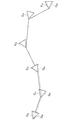
- FIG. 2 is an explanatory diagram for explaining an example of the self-position estimation technique, and shows an example of the estimation result of the position and orientation of the imaging unit in the real space by SLAM.
- markers indicated by reference numerals C 10 to C 15 schematically show changes in the position and orientation of the imaging unit (and thus the moving body 300) in real space in time series. That is, the example shown in FIG. 2 shows a case where the position and orientation of the imaging unit are sequentially shifted along the time series in the order of the markers C 10 to C 15 .
- the markers indicated by reference signs D 10 to D 15 schematically show the estimation results of the position and orientation of the imaging unit in the real space based on SLAM, and correspond to the markers C 10 to C 15 , respectively.
- the marker D 11 indicates the estimation result of the position and orientation of the imaging unit in the state where the position and orientation of the imaging unit are indicated by the marker C 11 .
- the position and orientation of the imaging unit in the following will be relative based on detection results of various sensors, for example. It is possible to estimate by sequentially acquiring information indicating a change.
- the estimation results D 11 ⁇ D 15 is as a base point and the estimation result D 10, it is possible to estimate by utilizing information indicating the position and relative change in the orientation in the real space of the imaging unit based on the detection results of various sensors.
- the position and orientation (that is, the absolute position) of the imaging unit in real space are indirectly estimated by sequentially acquiring relative changes in the position and orientation of the imaging unit, such as SLAM.
- so-called localization is important.
- localization is a process of estimating (or re-estimating) the position and orientation of the imaging unit in real space as an absolute position by self-position estimation based on an image captured by the imaging unit, for example. Show.
- FIG. 3 and FIG. 3 and 4 are explanatory diagrams for explaining an outline of localization.
- FIG. 3 shows an example when tracking of relative changes in the position and orientation of the imaging unit fails.
- the markers indicated by reference signs D 20 to D 22 schematically show the estimation results of the position and orientation of the imaging unit in the real space based on SLAM, and correspond to the markers C 10 to C 12 , respectively.
- the relative change in the position and orientation of the imaging unit between the marker C 12 and the marker C 13 is unknown, and the position of the imaging unit in the real space after the marker C 13. And the estimation of the posture becomes substantially difficult.
- the localization of the position and orientation of the imaging unit in real space may be restarted by localization to resume tracking of the position and orientation of the imaging unit.
- localization process at the timing corresponding to the marker C 15 is performed, the position and orientation in the real space of the imaging unit is again estimated as the absolute position.
- Marker indicated by reference numeral D 25 is the result of the re-estimation of the position and orientation in the real space of the imaging unit based on the localization process is schematically shown. That is, in the example illustrated in FIG. 3, by using the estimation result D 25 at the timing corresponding to the marker C 15 , it is possible to resume tracking of the position and orientation of the imaging unit after the marker C 15. Become.
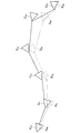
- FIG. 4 shows an example in which an error occurs between the estimation result of the relative change in the position and orientation of the imaging unit and the relative change in the actual position and orientation of the imaging unit.
- the estimation result of the relative change in the position and orientation of the imaging unit at the timing corresponding to each of the markers C 11 to C 14 .
- the estimation result of the relative change in the position and orientation of the imaging unit at the timing corresponding to each of the markers C 11 to C 14 .
- the estimation result of the relative change in the position and orientation of the imaging unit and the actual position and orientation of the imaging unit.
- There is an error between relative changes As described above, errors generated at each timing are sequentially accumulated as accumulated errors. From such characteristics, as long as tracking of relative changes in the position and orientation of the imaging unit is continued, the cumulative error tends to increase in proportion.
- the markers indicated by reference numerals D 30 to D 34 schematically show the estimation results of the position and orientation of the imaging unit in the real space based on SLAM, and correspond to the markers C 10 to C 14 , respectively.
- the position and orientation estimation result D 34 in the real space of the imaging unit and the actual real space of the imaging unit at the timing corresponding to the marker C 14 as the accumulation error increases.
- position and orientation i.e., the position and orientation illustrated marker C 14 is
- a visually similar scene may be captured as an image by the imaging unit.
- a scene in which a predetermined pattern appears repeatedly is captured as an image.
- a visually similar scene may be captured even when the position and orientation in the real space are different from each other.
- not only a scene in which a repetitive pattern appears, but also a visually similar scene may be captured as an image under a situation where the position and posture in the real space are different from each other. In such a case, the accuracy of self-position estimation is reduced, and as a result, the position and orientation of the target object (for example, the imaging unit and the moving object holding the imaging unit) in real space are estimated incorrectly. Such a situation is also assumed.
- the repetitive pattern is not limited to a two-dimensional pattern or the like, for example, a three-dimensional shape or the like can be assumed. As described above, in a situation where a repetitive pattern of a three-dimensional shape appears, even if object shape matching using a depth sensor or the like is performed, the validity of the posture parameter is determined (that is, the posture parameter is determined). It is difficult to prevent erroneous estimation.
- the position and orientation that is, the orientation parameter
- the position and orientation that is, the orientation parameter of the target object in the real space, such as the imaging unit and the moving body that holds the imaging unit.
- a plurality of imaging units that is, the moving body 300
- a plurality of imaging units that is, the moving body 300
- the main imaging unit 303 and the sub imaging unit 305) are held so as to have different optical axes (that is, optical axes L1 and L2).
- the relative positional relationship between the main imaging unit 303 and the sub imaging unit 305 can be handled as known information by calculating in advance as offset information, for example.
- each of the main imaging unit 303 and the sub imaging unit 305 may be configured as a monocular camera or may be configured as a stereo camera. Further, the main imaging unit 303 and the sub imaging unit 305 may have different configurations. In the following description, it is assumed that the main imaging unit 303 and the sub imaging unit 305 have the same configuration in order to make the technical features of the information processing system 1 according to the present embodiment easier to understand.
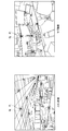
- FIG. 5 is an explanatory diagram for explaining an example of processing for registering data used for estimation of posture parameters in the information processing system according to the present embodiment.
- reference symbol P i corresponds to a portion that shows a visually identifiable feature such as shape, color, brightness and darkness in real space, and is hereinafter also referred to as “landmark”. That is, the landmark P i corresponds to the portion to be extracted as a feature point from an image captured by the imaging unit.
- the self-position estimation of the moving body 300 is performed by SLAM or the like while moving the moving body 300 in a space to be registered (ie, a real space).
- a space to be registered ie, a real space.
- reference symbols K n ⁇ 1 , K n , and K n + 1 schematically indicate changes in the position and orientation of the moving body 300 in the real space in time series. That is, the example shown in FIG. 5 shows a case where the position and orientation of the moving body 300 are sequentially changed along the time series in the order of K n ⁇ 1 , K n , and K n + 1 .
- an image of the space around the moving body 300 (that is, the real space) is captured by the imaging unit held by the moving body 300 according to each position and orientation. Is done. Then, the image analysis process is performed on the captured image, the position in the real space of the landmark P i captured in the image is estimated (calculated). At this time, the result of depth sensing using a stereo camera, a distance sensor, or the like may be used to estimate the position of the landmark Pi in the real space.
- the main imaging unit 303 and the sub imaging unit 305 are held with respect to the moving body 300. Therefore, together with the self-position estimation of the mobile body 300, on the basis of the images captured by the respective main imaging unit 303 and the sub-imaging unit 305, the position in the real space of each landmark P i captured in the image Estimated (calculated).
- a partial region of the in the image including the each landmark P i is extracted (calculated).
- FIG. 6 is an explanatory diagram for describing an example of information acquired from images captured by the main imaging unit 303 and the sub imaging unit 305, respectively.
- an image captured by the main imaging unit 303 is also referred to as a “main image”
- an image captured by the sub imaging unit 305 is also referred to as a “sub image”.
- reference symbol P i indicates a landmark captured in the image.
- Reference sign Q i corresponds to a partial region in the vicinity of the landmark P i in the image.
- the partial region Q i, for each landmark P i is set in the image as a partial area including the landmark P i.
- each of the captured main image and sub-image is subjected to image analysis processing, so that the land captured in the image is captured from each image.
- the mark P i is extracted as a feature point.
- the predetermined size of the partial region Q i is set for the feature points, respectively, for each set subregion Q i, the feature quantity in the partial region Q i (e.g., shape, color, and brightness And the like) are extracted as local feature amounts.
- a plurality of local feature values are extracted for one feature point (ie, a landmark). May be.
- each extraction of a local feature amount corresponding to the mark P i is performed sequentially.
- Each piece of information estimated or calculated for each position and orientation of the moving body 300 is associated as a series of data and registered (recorded) as a key frame in a predetermined storage area (for example, a database).
- FIG. 7 is a diagram showing an example of information registered as a key frame. Specifically, in the example illustrated in FIG. 7, information corresponding to the main imaging unit 303 and information corresponding to the sub imaging unit 305 are registered as key frames.
- the information corresponding to the main image pickup unit 303 for example, the position and orientation of the main imaging unit 303 (i.e., posture parameter) and estimation results, the position in the real space of the landmark P i that is captured in the main image and estimation result, the extraction result of the local feature quantity corresponding to each landmark P i, is included.
- the posture parameter of the main imaging unit 303 is acquired as a result of the self-position estimation of the moving body 300, for example.
- a plurality of landmarks Pi may be captured in the main image. Therefore, for each landmark P i , the estimation result of the position of the landmark P i in the real space and the extraction result of the local feature corresponding to the landmark P i are registered.
- the information corresponding to the sub imaging unit 305 includes, for example, the estimation result of the position of the landmark P i captured in the sub image in the real space, the extraction result of the local feature amount corresponding to each landmark P i , and Is included.
- the estimation result of the position and orientation of the main imaging unit 303 and the relative positional relationship between the main imaging unit 303 and the sub imaging unit 305 It is possible to calculate based on the above. Further, as described above, the relative positional relationship between the main imaging unit 303 and the sub imaging unit 305 can be handled as known information by calculating in advance as offset information.
- the main imaging unit 303 (and hence, the moving body 300) for each position and orientation of an estimation result of the position in the real space of the landmark P i taken respectively main image and sub-image Then, the extraction result of the local feature amount corresponding to each landmark P i is registered.
- Each information registered as a key frame as described above is used as data to be compared with a feature amount extracted from an image captured by an imaging unit when estimating a posture parameter in localization or the like. Become.
- each image that is, the main image and the sub image
- aquery image is also referred to as a “query image”
- key frame image is also referred to as a “key frame image”.
- the information processing apparatus 100 illustrated in FIG. 1 performs processing related to posture parameter estimation in localization or the like.
- the information processing apparatus 100 performs matching of local feature amounts extracted from each image between the query image and the key frame image for the main image. Then, the posture parameter of the main imaging unit 303 (and thus the moving body 300) is estimated.
- FIG. 8 is an explanatory diagram for explaining an overview of processing related to posture parameter estimation.
- An example of i setting results is shown.
- FIG. 8 shows an example in which the position and orientation (that is, the orientation parameter) of the main imaging unit 303 (and thus the moving body 300) substantially match between the query image and the key frame image. Is shown.
- a landmark P i that is substantially the same as the landmark P i captured in at least a part of the key frame image is captured in at least a part of the query image.
- the landmarks P i corresponding to the partial areas Q i that are associated with each other by a broken line between the query image and the key frame image indicate the same position in the real space.
- the local feature amounts between the corresponding partial areas Q i substantially coincide with each other.
- the information processing apparatus 100 estimates a posture parameter of the main imaging unit 303 (and thus the moving body 300) when the query image is captured. Specifically, the information processing apparatus 100, information about the feature amounts extracted from the query image (i.e., information about the landmark P i, an information local feature amount corresponding to the landmark P i) substantially coincides with the Search for keyframes that contain information. Then, the information processing apparatus 100 estimates the posture parameter of the main imaging unit 303 when the query image is captured based on the posture parameter of the main imaging unit 303 included in the searched key frame. Note that the details of the processing related to the estimation of the posture parameter associated with the matching of the local feature amount between the query image and the key frame image will be described later.
- a visually similar scene may be captured as an image even when the position and posture in the real space are different from each other.
- the accuracy related to the estimation of the posture parameter of the main imaging unit 303 is reduced, and as a result, the posture parameter may be estimated incorrectly.
- the information processing system 1 according to the present embodiment by using the sub-image captured by the sub-imaging unit 305, the accuracy related to the estimation of the posture parameter is further improved, and Prevent false estimates.
- FIGS. 9 to 12 are explanatory diagrams for explaining the basic principle of the process related to the estimation of the posture parameter in the information processing system 1 according to the present embodiment.
- FIG. 9 shows an example where similar scenes are captured as main images when the query image and the key frame image are captured at different positions. Under such circumstances, the feature amounts extracted from each main image are substantially the same, and the posture parameter of the main imaging unit 303 may be erroneously estimated only by estimation using the main image.
- the sub imaging unit 305 is held so as to have an optical axis different from that of the main imaging unit 303, and images a scene (in other words, a different area in real space) different from the main imaging unit 303. It will be. For this reason, as shown in FIG. 9, even when the query image and the main image captured as the key frame image are similar to each other, the non-interval between the query image and the sub image captured as the key frame image is not. It may be similar.
- the estimation result of the posture parameter of the main imaging unit 303 (and thus the moving body 300) based on the main image is used as a corresponding sub-image.
- I will verify it. Specifically, as shown in FIG. 10, by performing matching of feature amounts extracted from each of the query image and the sub-image captured as the key frame image, the likelihood of the estimation result of the posture parameter based on the main image is confirmed. To verify.
- the main image is also referred to as a “key frame main image” and the sub image is referred to as a “key frame image”. Also referred to as “sub-image”.
- the main image is also referred to as a “query main image”
- the sub image is also referred to as a “query sub image”.
- FIG. 11 is an explanatory diagram for explaining an overview of a process related to verification of a posture parameter estimation result in the information processing system 1 according to the present embodiment.
- the local feature amount extracted from each image is also between the key frame sub image and the query sub image. It will be approximately the same. That is, in such a case, the landmark P i that is substantially the same as the landmark P i captured in at least a part of the key frame sub image is captured in at least a part of the query sub image. .
- the information processing apparatus 100 first recorded as keyframes, and information about the landmark P i which is extracted from the key frames sub-image, and the query main image and attitude parameters estimated by the keyframe main image , Each landmark P i is projected onto the query sub-image. Then, the information processing apparatus 100, for each point in each landmark P i is Kuerisabu image projected, extracts a local feature amount of the partial area including the point (calculated). For example, in FIG. 11, a region indicated by reference symbol R i indicates a partial region including a point on which the landmark P i is projected.
- the information processing apparatus 100 calculates the local feature amount calculated for each point projected in the query sub-image (that is, the local feature amount of each partial area R i ), and the projection source of the point recorded as a key frame. Matching is performed between the local feature amount corresponding to the landmark P i (that is, the local feature amount of each partial region Q i ). Then, based on the matching result, the information processing apparatus 100 determines that the posture parameter estimation result based on the main image (that is, the localization result) is correct if the number of inlier points is equal to or greater than the threshold value. .
- the information processing apparatus 100 includes the feature amount extracted from the sub-image captured by the sub-imaging unit 305 and the feature amount extracted from the sub-image included in the information registered as the key frame. By comparing, the position and orientation of the moving body 300 are estimated. That is, as illustrated in FIG. 12, the information processing apparatus 100 estimates the position and orientation of the moving object 300 (ie, when the feature amounts extracted from the key frame sub-image and the query sub-image substantially match each other) , The estimated camera position) is substantially coincident with the actual position and orientation of the moving body 300 (that is, the true camera position).
- the information processing system 1 it is possible to further improve the accuracy related to the estimation of the position and orientation (that is, the orientation parameter) of the mobile object 300 in the real space. As a result, it is possible to prevent erroneous estimation of the position and the attitude.
- FIG. 13 is a block diagram illustrating an example of a functional configuration of the information processing system 1 according to the present embodiment.
- the information processing system 1 has a system configuration as shown in FIG. 1 and estimates the position and orientation of the moving body 300.
- the information processing system 1 includes an information processing apparatus 100, a moving body 300, and a storage unit 150.
- the information processing apparatus 100 and the moving body 300 illustrated in FIG. 13 correspond to the information processing apparatus 100 and the moving body 300 illustrated in FIG. That is, the moving body 300 includes a main imaging unit 303 and a sub imaging unit 305. Since the main imaging unit 303 and the sub imaging unit 305 have been described above, detailed description thereof will be omitted.
- the storage unit 150 is a storage area for storing various data temporarily or permanently.
- the storage unit 150 may store data corresponding to each key frame acquired by the registration process described above.
- the storage unit 150 is configured to be able to individually read various stored data.
- the storage unit 150 may be configured as a database, for example.
- the information processing apparatus 100 includes an estimation unit 101 and a verification unit 103.
- the estimation unit 101 acquires an image (that is, a main image) captured by the main imaging unit 303 held by the moving body 300 from the moving body 300 (or the main imaging unit 303).
- the image corresponds to the query main image.
- Estimation unit 101 by performing image analysis on the acquired query main image, and extracts a position corresponding to the landmark P i captured in the query main image as feature points.
- algorithms for extracting feature points include, for example, Harris corner detector, FAST corner detector, and Difference of Gaussian.
- the estimation unit 101 sets a partial area Q i having a predetermined area including the feature point, and extracts (calculates) a local feature amount in the partial area Q i . After that, the extraction result of the local feature amount is associated with the partial region Q i .
- algorithms for extracting local feature values include SIFT, BRISK, and ORB.
- the estimation unit 101 determines that information similar to the feature amount extracted from the query main image (that is, the local feature amount corresponding to each partial region Q i set for each landmark P i ) is information on the key frame main image. Keyframes included in the storage unit 150 are searched for and extracted from the keyframes stored in the storage unit 150.
- the estimation unit 101 performs matching between each of the local feature values extracted from the query main image and each of the local feature values extracted from the key frame main image included in each key frame. I do. And the estimation part 101 may count the pair which shows the similarity of a local feature-value more than a threshold value as a score, and may extract a key frame based on the calculation result of the said score. As another example, the estimation unit 101 may extract a key frame based on a calculation result of the score by using a similarity of a Bag of Words feature value created from the local feature value as a score.
- the estimation unit 101 performs matching between the feature amount extracted from the query main image and the feature amount included as information of the key frame main image in each extracted key frame, whereby the main imaging unit 303 ( As a result, the posture parameters of the moving body 300) are estimated.
- the main imaging unit 303 As a result, the posture parameters of the moving body 300
- two-dimensional feature amount information and landmark information corresponding to the feature amount are stored for each key frame. Therefore, by matching the two-dimensional feature value obtained from the query main image with the two-dimensional feature value of the key frame, the key frame has the two-dimensional feature value of the query main image.
- Matching with a landmark as three-dimensional information that is, 2D-3D matching
- a method for estimating the attitude parameter by 2D-3D matching for example, a method based on the PNP algorithm using the RANSAC framework can be cited.
- the estimation unit 101 also includes the top N keys (N is an arbitrary natural number) including information having higher similarity to the feature amount extracted from the query main image from the key frames stored in the storage unit 150.
- a frame may be extracted.
- N key frames are used for posture parameter estimation, N estimation results are obtained. Even when a plurality of estimation results are obtained, it is possible to select the most probable estimation result by verification by the verification unit 103 described later.
- the estimation part 101 outputs the estimation result of the attitude
- FIG. 1 After all the key frames stored in the storage unit 150 have been matched and the posture parameter estimation still fails, the verification by the verification unit 103 described later is not performed, and the posture parameter estimation fails. Will be output.
- the verification unit 103 acquires an image (that is, a sub image) captured by the sub imaging unit 305 held in the moving body 300 from the moving body 300 (or the sub imaging unit 305). Note that the image corresponds to a query sub-image.
- the verification unit 103 acquires the estimation result of the posture parameter of the main imaging unit 303 from the estimation unit 101. Then, the verification unit 103 verifies the certainty of the acquired estimation result of the posture parameter using the acquired query sub-image.
- an example of processing related to the verification will be described in more detail.
- the verification unit 103 based on the information on the landmark P i extracted from the key frame sub-image included in the key frame corresponding to the obtained posture parameter estimation result, and the obtained posture parameter, Each mark P i is projected onto the acquired query sub-image.
- the point at which the landmark has been extracted from the key frame sub-image P i is projected also referred to as "projection point”.
- the verification unit 103 extracts (calculates) the local feature amount of the partial region R i including the projection point for each projection point in the query sub-image. Also, the verification unit 103 corresponds to the landmark P i that is the projection source of the projection point included in the key frame corresponding to the local feature amount calculated for each projection point in the query sub-image and the estimation result of the posture parameter. The degree of similarity with the local feature amount to be calculated is calculated. Then, the verification unit 103, among the projected point Kuerisabu in the image each landmark P i is projected, the local feature quantity similarity counts more than a threshold as inliers. Note that examples of the feature amount and the similarity used in the processing include an SAD score and an NCC score that use the luminance of the image itself as a feature amount.
- the verification unit 103 assumes at least one of the query sub image and the key frame sub image according to the estimation result of the posture parameter of the main imaging unit 303, and the corresponding image feature amount (that is, The local feature amount of each part) may be corrected. In this case, the verification unit 103 may calculate the similarity based on the corrected feature amount.
- the verification part 103 determines with the estimation result of a corresponding attitude
- the verification unit 103 determines that the estimation result of the posture parameter is valid, the verification unit 103 outputs the estimation result to a predetermined output destination.
- the verification unit 103 may, for example, select a higher estimation result reliability and execute the processing related to the verification. As another example, the verification unit 103 performs the process related to the verification on each of a plurality of estimation results, and outputs the most probable estimation result as the estimation result of the posture parameter of the main imaging unit 303. Also good.
- the functional configuration of the information processing system 1 is merely an example, and if the functions of the respective configurations described above are realized, the functional configuration of the information processing system 1 is not necessarily in the example illustrated in FIG. It is not limited. As a specific example, at least two or more of the information processing apparatus 100, the storage unit 150, and the moving body 300 may be integrally configured. In addition, some of the components included in the information processing apparatus 100 may be provided in another apparatus different from the information processing apparatus 100. In addition, each function of the information processing apparatus 100 may be realized by cooperation of a plurality of apparatuses.
- information about the feature amount extracted from the key frame image (for example, information about the landmark P i, information on local feature amount corresponding to the landmark P i) is registered in advance as keyframes
- the key frame image itself may be registered as a key frame.
- the feature amount for example, from the key frame image (that is, the key frame main image or the key frame sub-image) registered as the key frame when estimating the posture parameter or verifying the estimation result. It may be extracted.
- the query image and the key frame image may be deformed according to the estimation result of the posture parameter of the main imaging unit 303.
- FIG. 14 to FIG. 16 are flowcharts showing an example of a flow of a series of processes of the information processing system 1 according to this embodiment.
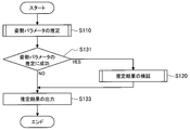
- the information processing apparatus 100 acquires an image (that is, a query main image) captured by the main imaging unit 303 held by the moving body 300 from the moving body 300. . Then, the information processing apparatus 100 extracts a feature amount from the acquired query main image, and extracts the extracted feature amount from information related to the feature amount included in a key frame stored in a predetermined storage area (storage unit 150). By comparing, the posture parameter of the moving body 300 is estimated (S110).
- the information processing apparatus 100 verifies the estimation result. Specifically, the information processing apparatus 100 (verification unit 103) acquires an image (that is, a query sub-image) captured by the sub imaging unit 305 held in the moving body 300 from the moving body 300. Then, the information processing apparatus 100 extracts a feature amount from the acquired query sub-image, and compares the extracted feature amount with information regarding the feature amount included in the key frame corresponding to the estimation result of the posture parameter of the mobile object 300. Thus, the certainty of the estimation result is verified (S120).
- the information processing apparatus 100 outputs the estimation result of the posture parameter of the moving body 300 to a predetermined output destination based on the verification result (S133).
- the information processing apparatus 100 does not execute the process related to the verification indicated by reference numeral S120.
- information indicating failure in estimation of the posture parameter is output (S133).
- the information processing apparatus 100 (estimating unit 101), by performing image analysis on the acquired query main image, and extracts a position corresponding to the landmark P i captured in the query main image as feature points (S111).
- the information processing apparatus 100 (estimating unit 101) sets a partial region Q i including the feature point, and extracts (calculates) a local feature amount in the partial region Q i . ) And associate the extraction result of the local feature quantity with the partial area Q i (S113).
- the information processing apparatus 100 uses the key frame stored in the storage unit 150 as a key frame including information similar to the feature amount extracted from the query main image as information of the key frame main image. Search and extract from the inside (S115).
- the information processing apparatus 100 (estimating unit 101) performs matching between the feature amount extracted from the query main image and the feature amount included as information of the key frame main image in each extracted key frame. Then, the posture parameter of the moving body 300 is estimated (S117).
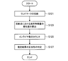
- the information processing apparatus 100 includes information on the landmark P i extracted from the key frame sub-image included in the key frame corresponding to the posture parameter estimation result, the posture parameter estimation result, based on, projected to the landmark P i Kuerisabu image acquired respectively (S121).
- the information processing apparatus 100 extracts (calculates) a local feature amount of a partial region including the projection point. Further, the information processing apparatus 100 includes a local feature amount calculated for each projected point in Kuerisabu image, included in key frame corresponding to the estimation result of the attitude parameters, the landmark P i as a projection source of the projection point The similarity with the corresponding local feature is calculated (S123).
- the information processing apparatus 100 (verification unit 103), among the projection points in the Kuerisabu images each landmark P i is projected, the local feature quantity similarity counts more than a threshold value as inliers (S125 ).
- the information processing apparatus 100 determines that the corresponding posture parameter estimation result is valid. (S127).
- Modification 1 Example of processing related to verification of posture parameter estimation result
- the information processing apparatus 100 matches the feature amount extracted from the query sub image with the feature amount registered in advance as a key frame (that is, the feature amount extracted from the key frame sub image). The accuracy of the estimation result of the posture parameter was verified.
- the method is not particularly limited as long as the likelihood of the estimation result of the posture parameter can be verified based on the sub image captured by the sub image capturing unit 305.
- the information processing apparatus 100 verifies the accuracy of the estimation result of the posture parameter by comparing the global feature amount of each image between the query sub image and the key frame sub image. May be. Specifically, the information processing apparatus 100 extracts, for example, a Bag of Words feature amount, a color histogram feature amount, and the like as a global feature amount from each of the query sub image and the key frame sub image. Then, the information processing apparatus 100 may determine that the estimation result of the posture parameter is valid when the similarity of the feature amount extracted from each image exceeds a threshold value.
- the information processing apparatus 100 may use a discriminator generated in accordance with so-called machine learning for verification of a posture parameter estimation result.
- a discriminator generated in accordance with so-called machine learning for verification of a posture parameter estimation result.
- the discriminator is trained with the image as data and the image that should not be observed as negative data.
- the discriminator is recorded in a predetermined storage area (for example, the storage unit 150) in association with the position and orientation of the imaging unit.
- the information processing apparatus 100 searches for a discriminator associated with a position and posture that substantially matches the posture parameter estimation result, and is captured by the sub imaging unit 305.
- the query sub-image may be input to the classifier.
- FIG. 17 is a flowchart illustrating an example of a flow of a series of processes of the information processing system 1 according to the second modification, and particularly illustrates an example of a process related to verification of a posture parameter estimation result in localization or the like.
- the information processing apparatus 100 selects any one of a plurality of main imaging units 303 held by the moving body 300 and images (that is, queries) captured by the selected main imaging unit 303. Main image) is acquired from the moving object 300. Then, the information processing apparatus 100 estimates the posture parameter of the moving body 300 based on the acquired query main image (S210). Note that the processing related to the estimation of the posture parameter of the moving body 300 is the same as the processing described above with reference to FIG.
- the information processing apparatus 100 verifies the estimation result (S220). Note that the processing related to the verification of the estimation result of the posture parameter of the moving object 300 is the same as the processing described above with reference to FIG.
- the information processing apparatus 100 determines that the estimation result of the posture parameter of the moving body 300 is appropriate (S233, YES), the information processing apparatus 100 outputs the estimation result to a predetermined output destination (S239).
- the information processing apparatus 100 determines that the estimation result of the posture parameter of the moving body 300 is not valid (S233, NO), the other main imaging unit 303 that is not used for the posture parameter estimation is used. It is confirmed whether or not selection is possible (S235). If another main imaging unit 303 can be selected (S235, YES), the information processing apparatus 100 newly selects another main imaging unit 303 (S237), and processing related to posture parameter estimation (S210). And try again. When it is difficult to select another main imaging unit 303 (S235, NO), the information processing apparatus 100 outputs information indicating a posture parameter estimation failure (S239).
- the information processing apparatus 100 does not use other main imaging units that are not used for posture parameter estimation even when the posture parameter estimation of the moving object 300 fails in the process indicated by reference numeral S210 (NO in S231). It is confirmed whether or not 303 can be selected (S235). If another main imaging unit 303 is selectable (S235, YES), the information processing apparatus 100 newly selects another main imaging unit 303 (S237), and performs processing related to posture parameter estimation (S237). Execute again from S210). When it is difficult to select another main imaging unit 303 (S235, NO), the information processing apparatus 100 outputs information indicating a posture parameter estimation failure (S239).
- the information processing apparatus 100 sequentially switches the main imaging unit 303 used for posture parameter estimation, and Estimate the parameters again. With such control, the information processing apparatus 100 can reestimate the posture parameter using another main imaging unit 303 even when the estimation of the posture parameter using some of the main imaging units 303 fails. Is possible. Therefore, according to the information processing system according to the second modification, it is possible to further reduce the probability that posture parameter estimation fails.
- not all the main imaging units 303 are necessarily used for estimating the posture parameters of the moving body 300. Therefore, it is possible to reduce the processing load related to the estimation as compared to the case where all of the plurality of main imaging units 303 are always used for the estimation of posture parameters.
- the information processing apparatus 100 for example, the landmark P extracted from the key frame sub-image based on the information included in the key frame corresponding to the posture parameter estimation result and the posture parameter estimation result. i is projected onto each query sub-image captured by the plurality of sub-imaging units 305.
- the information processing apparatus 100 performs inlier determination for each projection point for each of the plurality of query sub-images, and determines the validity of the estimation result of the posture parameter according to the number of inliers.
- the information processing apparatus 100 sets the posture parameter estimation result to a predetermined output destination. Just output.
- FIG. 18 is a flowchart illustrating an example of a flow of a series of processes of the information processing system 1 according to the modification example 4, and particularly illustrates an example of a process related to verification of an estimation result of posture parameters in localization or the like.
- the information processing apparatus 100 is used for posture parameter estimation when the posture parameter estimation fails (S331, NO) or when the posture parameter estimation result is determined to be invalid (S333, NO). It is confirmed whether another main imaging unit 303 that is not selected can be selected (S335). If it is difficult to select another main imaging unit 303 (S335, NO), the information processing apparatus 100 determines whether the main imaging unit 303 and the sub imaging unit 305 can be switched (that is, the main imaging unit 303). It is determined whether or not the roles of the imaging unit 303 and the sub imaging unit 305 can be interchanged (S339).
- the information processing apparatus 100 replaces the imaging unit previously set as the sub imaging unit 305 with the new main imaging unit 303. Select (set) as. Further, the information processing apparatus 100 selects (sets) the imaging unit that has been previously set as the main imaging unit 303 as a new sub imaging unit 305 (S341). Then, the information processing apparatus 100 executes again from the process (S310) related to the estimation of the posture parameter.
- the information processing apparatus 100 If it is difficult to switch between the main imaging unit 303 and the sub imaging unit 305 (S339, NO), the information processing apparatus 100 outputs information indicating a failure in estimating the posture parameter (S343).
- Modification 4 referring to FIG. 18, the control in the case of selectively switching the roles of the main imaging unit 303 and the sub imaging unit 305 according to the estimation result of the posture parameter and the estimation result is used. An example has been described.
- the information processing apparatus 100 calculates in advance a uniqueness score for each of a series of key frame images registered as key frames (that is, a key frame main image and a key frame sub-image).
- the uniqueness score is a score that indicates how unique each image has to the other images.
- the variables I_i and I_j indicate the feature amounts of the image i and the image j, respectively.
- the similarity function corresponds to a function for calculating a similarity between input information (image feature amounts).
- image feature amounts a global feature amount such as Bag of Words that represents the characteristics of the entire image.
- the similarity between two images may be calculated by matching local feature amounts between two images and counting the number of inliers.
- the information processing apparatus 100 searches for an image similar to the query image captured by each imaging unit (for example, the main imaging unit 303 and the sub imaging unit 305) from the key frame images registered as key frames. Next, the information processing apparatus 100 identifies a key frame image having a higher uniqueness score among the key frame images searched for each query image. Then, the information processing apparatus 100 sets a query image corresponding to the identified key frame image as a query main image, sets other query images as query sub-images, and then estimates the posture parameter or sets the posture parameter. Verify the estimation results.
- the information processing system according to the modified example 5 it is possible to perform self-position estimation using an image that is expected to have a more unique feature. It is also possible to further improve the accuracy. Further, according to the information processing system according to the modified example 5, due to the above-described characteristics, for example, an image in which a similar scene may be captured like an image in which a repeated pattern is captured is self-position estimation. It is also possible to prevent the occurrence of a situation used for
- Modification 6 Example of control related to selection of sub imaging unit
- the moving body 300 is configured as a vehicle, and the position and orientation (that is, the orientation parameter) of the vehicle in real space are estimated by using an imaging unit mounted on the vehicle. An example of the case will be described.
- the image is oriented in a direction rotated 90 degrees to the left and right from the traveling direction (that is, the left and right direction of the vehicle) rather than the imaging unit facing the traveling direction of the vehicle.
- the change in the scene to be imaged is greater as the vehicle moves.
- the amount of change in the scene captured as an image with respect to the amount of change in the attitude parameter of the vehicle is more in the image pickup unit that faces the left and right direction of the vehicle than in the image pickup unit that faces in the traveling direction of the vehicle. Expected to grow.
- each imaging unit facing in the left-right direction of the vehicle may be used as the main imaging unit 303 and the sub imaging unit 305.
- the imaging unit facing one of the left and right directions of the vehicle is set as the main imaging unit 303, and the imaging unit facing the other (that is, the imaging unit facing the opposite direction to the main imaging unit 303) is set as the sub. It may be set as the imaging unit 305.
- the posture parameter of the moving body 300 is estimated. It becomes possible to further improve the accuracy and accuracy related to the verification of the estimation result.
- Modification 6 there has been described an example of control related to selection of the sub imaging unit 305 used for verification of the posture parameter estimation result when a plurality of sub imaging units 305 are set.
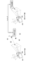
- FIG. 19 is an explanatory diagram for explaining the outline of the information processing system according to the modification 7.
- the imaging unit 305 In self-position estimation using an image captured by the imaging unit, a certain common visual field is required between the image registered in the database and the image acquired at the time of estimation, and is generally common. The wider the field of view, the more robust the estimation results. This also applies to the verification of the posture parameter estimation result using the sub imaging unit 305.
- an example of a selection method of the sub imaging unit 305 in view of such a situation will be described.
- the key frame image described above corresponds to an image registered in the database or the like
- the query image described above corresponds to an image acquired at the time of the estimation.
- the storage unit 150 described with reference to FIG. 13 corresponds to the database and the like.
- the posture parameter of the main imaging unit 303 (and thus the moving body 300) is estimated based on the main image captured by the main imaging unit 303. Do. In addition, if calibration is performed on the relative positional relationship between the imaging units held by the moving body 300, an imaging unit other than the main imaging unit 303 (for example, for example, based on the estimation result of the posture parameter). It is also possible to estimate (calculate) the attitude parameter of the sub imaging unit 305).
- the information processing apparatus 100 includes, for each of the plurality of sub imaging units 305, information indicating the attitude of the sub imaging unit 305 based on information registered as a key frame, and an object of attitude parameter estimation.
- the information indicating the attitude of the sub imaging unit 305 is compared.
- information indicating the posture of an object such as the sub imaging unit 305 is also referred to as a “rotation parameter”.
- the information processing apparatus 100 is based on the optical axis direction vector of the imaging unit calculated from the corresponding rotation parameter among the plurality of sub imaging units 305 and information registered as key frames.
- the sub-imaging unit 305 showing a value closer to the angle difference between the optical axis direction vector of the imaging unit calculated in this way is selected.
- the diagram on the left schematically shows the posture of the moving body 300 according to the information registered as the key frame. Further, the diagram on the right side schematically shows the actual posture of the moving body 300 that is the target of posture parameter estimation.
- a main imaging unit 303 and a plurality of sub imaging units 305 a and 305 b are held in the housing 301 of the moving body 300. Further, each of the main imaging unit 303, the sub imaging unit 305a, and the sub imaging unit 305b is held so as to capture different directions with respect to the moving body 300. That is, the optical axis direction vector of the imaging unit is set so as to capture different directions. For example, in FIG.
- a direction indicated as “main” indicates a direction in which the main imaging unit 303 captures an image.
- the direction indicated as “sub1” indicates the direction in which the sub imaging unit 305a captures an image.
- the direction indicated as “sub2” indicates the direction in which the sub imaging unit 305b captures an image.
- the information processing apparatus 100 determines, for each of the sub imaging units 305 a and 305 b, the imaging unit calculated from the rotation parameters of the imaging unit based on the information registered as the key frame.
- the optical axis direction vector is compared with the optical axis direction vector of the imaging unit calculated from the rotation parameter of the imaging unit calculated according to the estimation result of the posture parameter.
- the information processing apparatus 100 is registered as a key frame and an optical axis direction vector of the imaging unit according to the estimation result of the posture parameter, according to the comparison result, of the sub imaging units 305a and 305b.
- the sub imaging unit 305 having a closer angle difference from the optical axis direction vector of the imaging unit based on the information is selected.
- the imaging direction sub ⁇ b> 1 indicated by the information registered as the key frame is different from the imaging direction sub ⁇ b> 1 corresponding to the actual posture of the moving body 300. Therefore, in the example illustrated in FIG. 19, for the sub imaging unit 305a, a scene different from the scene captured as the key frame image is captured as the query image. Therefore, for the sub imaging unit 305a, the common field of view between the key frame image and the query image tends to be narrower, and as a result, there is a possibility that the common field of view does not exist.
- the imaging direction sub2 indicated by the information registered as the key frame is substantially equal to the imaging direction sub2 corresponding to the actual posture of the mobile object 300. Therefore, in the example shown in FIG. 19, for the sub imaging unit 305b, a scene similar to the scene captured as a key frame image is obtained except for the difference in the rotation direction about the optical axis of the sub imaging unit 305b. It will be taken as a query image. Therefore, for the sub imaging unit 305b, the common field of view between the key frame image and the query image is wider than that of the sub imaging unit 305a.
- the information processing apparatus 100 selects the sub imaging unit 305b having a wider common field of view between the key frame image and the query image among the sub imaging units 305a and 305b.
- the information processing system uses such characteristics and compares the imaging direction (that is, the optical axis direction vector of the imaging unit) between the key frame image and the query image as described above.
- the sub imaging unit 305 having a wider common field of view is selected.
- the information processing apparatus 100 uses a common visual field between the key frame image and the query image among the plurality of sub imaging units 305. It is possible to select a sub imaging unit 305 that is wide (that is, smaller in visual field change). Therefore, according to the information processing system 1 according to the modification example 7, it is possible to further improve the accuracy related to the verification of the estimation result of the posture parameter of the moving body 300.
- FIG. 20 is a functional block diagram illustrating a configuration example of the hardware configuration of the information processing apparatus configuring the information processing system according to an embodiment of the present disclosure.
- the information processing apparatus 900 constituting the information processing system according to the present embodiment mainly includes a CPU 901, a ROM 902, and a RAM 903.
- the information processing apparatus 900 further includes a host bus 907, a bridge 909, an external bus 911, an interface 913, an input device 915, an output device 917, a storage device 919, a drive 921, and a connection port 923. And a communication device 925.
- the CPU 901 functions as an arithmetic processing unit and a control unit, and controls all or a part of the operation in the information processing apparatus 900 according to various programs recorded in the ROM 902, the RAM 903, the storage apparatus 919, or the removable recording medium 927.
- the ROM 902 stores programs used by the CPU 901, calculation parameters, and the like.
- the RAM 903 primarily stores programs used by the CPU 901, parameters that change as appropriate during execution of the programs, and the like. These are connected to each other by a host bus 907 constituted by an internal bus such as a CPU bus.
- the estimation unit 101 and the verification unit 103 illustrated in FIG. 13 can be configured by the CPU 901.
- the host bus 907 is connected to an external bus 911 such as a PCI (Peripheral Component Interconnect / Interface) bus via a bridge 909.
- an input device 915, an output device 917, a storage device 919, a drive 921, a connection port 923, and a communication device 925 are connected to the external bus 911 via an interface 913.
- the input device 915 is an operation means operated by the user, such as a mouse, a keyboard, a touch panel, a button, a switch, a lever, and a pedal. Further, the input device 915 may be, for example, remote control means (so-called remote control) using infrared rays or other radio waves, or an external connection device such as a mobile phone or a PDA corresponding to the operation of the information processing device 900. 929 may be used. Furthermore, the input device 915 includes an input control circuit that generates an input signal based on information input by a user using the above-described operation means and outputs the input signal to the CPU 901, for example. A user of the information processing apparatus 900 can input various data and instruct a processing operation to the information processing apparatus 900 by operating the input device 915.
- the output device 917 is a device that can notify the user of the acquired information visually or audibly. Examples of such devices include CRT display devices, liquid crystal display devices, plasma display devices, EL display devices, display devices such as lamps, audio output devices such as speakers and headphones, printer devices, and the like.
- the output device 917 outputs results obtained by various processes performed by the information processing apparatus 900. Specifically, the display device displays results obtained by various processes performed by the information processing device 900 as text or images.
- the audio output device converts an audio signal composed of reproduced audio data, acoustic data, and the like into an analog signal and outputs the analog signal.
- the storage device 919 is a data storage device configured as an example of a storage unit of the information processing device 900.
- the storage device 919 includes, for example, a magnetic storage device such as an HDD (Hard Disk Drive), a semiconductor storage device, an optical storage device, or a magneto-optical storage device.
- the storage device 919 stores programs executed by the CPU 901 and various data.
- the storage unit 150 illustrated in FIG. 13 may be configured by the storage device 919.
- the drive 921 is a reader / writer for a recording medium, and is built in or externally attached to the information processing apparatus 900.
- the drive 921 reads information recorded on a removable recording medium 927 such as a mounted magnetic disk, optical disk, magneto-optical disk, or semiconductor memory, and outputs the information to the RAM 903.
- the drive 921 can also write a record to a removable recording medium 927 such as a magnetic disk, an optical disk, a magneto-optical disk, or a semiconductor memory that is mounted.
- the removable recording medium 927 is, for example, a DVD medium, an HD-DVD medium, a Blu-ray (registered trademark) medium, or the like.
- the removable recording medium 927 may be a compact flash (registered trademark) (CF: CompactFlash), a flash memory, an SD memory card (Secure Digital memory card), or the like. Further, the removable recording medium 927 may be, for example, an IC card (Integrated Circuit card) on which a non-contact IC chip is mounted, an electronic device, or the like.
- CF CompactFlash
- SD memory card Secure Digital memory card
- the connection port 923 is a port for directly connecting to the information processing apparatus 900.
- Examples of the connection port 923 include a USB (Universal Serial Bus) port, an IEEE 1394 port, a SCSI (Small Computer System Interface) port, and the like.
- As another example of the connection port 923 there are an RS-232C port, an optical audio terminal, an HDMI (registered trademark) (High-Definition Multimedia Interface) port, and the like.
- the communication device 925 is a communication interface configured with, for example, a communication device for connecting to a communication network (network) 931.
- the communication device 925 is, for example, a communication card for wired or wireless LAN (Local Area Network), Bluetooth (registered trademark), or WUSB (Wireless USB).
- the communication device 925 may be a router for optical communication, a router for ADSL (Asymmetric Digital Subscriber Line), a modem for various communication, or the like.
- the communication device 925 can transmit and receive signals and the like according to a predetermined protocol such as TCP / IP, for example, with the Internet or other communication devices.
- the communication network 931 connected to the communication device 925 is configured by a wired or wireless network, and may be, for example, the Internet, a home LAN, infrared communication, radio wave communication, satellite communication, or the like. .
- a computer program for realizing each function of the information processing apparatus 900 constituting the information processing system according to the present embodiment as described above can be produced and mounted on a personal computer or the like.
- a computer-readable recording medium storing such a computer program can be provided.
- the recording medium is, for example, a magnetic disk, an optical disk, a magneto-optical disk, a flash memory, or the like.
- the above computer program may be distributed via a network, for example, without using a recording medium.
- the number of computers that execute the computer program is not particularly limited.
- the computer program may be executed by a plurality of computers (for example, a plurality of servers) in cooperation with each other.
- the main imaging unit 303 and the sub imaging unit 305 are provided on the casing 301 of the moving body 300 that is the target of posture parameter estimation. Is held. Based on such a configuration, the information processing apparatus 100 estimates the position and orientation (that is, the orientation parameter) of the moving body 300 in the real space based on the main image captured by the main imaging unit 303. Further, the information processing apparatus 100 verifies the accuracy of the estimation result of the position and orientation of the moving body 300 based on the sub image captured by the sub image capturing unit 305.
- the information processing system 1 According to the configuration as described above, according to the information processing system 1 according to the present embodiment, it is possible to further improve the accuracy related to the estimation of the position and orientation of the mobile object 300 in the real space. And erroneous estimation of the posture can be prevented.
- the main imaging unit 303 corresponds to an example of a “first imaging unit”, and the main image captured by the main imaging unit 303 corresponds to an example of a “first image”.
- the sub imaging unit 305 corresponds to an example of a “second imaging unit”, and the sub image captured by the sub imaging unit 305 corresponds to an example of a “second image”.
- the following configurations also belong to the technical scope of the present disclosure.
- (1) Estimation that estimates at least one of a position and a posture of the casing in real space based on a first image captured by the first imaging section among a plurality of imaging sections held in a predetermined casing.
- a verification unit that verifies the likelihood of the estimation result based on a second image captured by a second imaging unit having an optical axis different from that of the first imaging unit among the plurality of imaging units;
- An information processing apparatus comprising: (2)
- the verification unit includes a first feature amount extracted from the second image and a second feature amount recorded in advance in association with at least one of a position and a posture of the housing in real space.
- the information processing apparatus according to (1) wherein the likelihood of the estimation result is verified.
- the second feature amount is acquired based on the second image captured by the second imaging unit according to at least one of a position and a posture of the housing in real space, The information processing apparatus according to (2).
- the verification unit records a feature value corresponding to each of one or more feature points extracted as the first feature value from the second image used for verification of the estimation result, and the second feature value.
- the information processing apparatus according to (3) wherein the likelihood of the estimation result is verified by comparing the feature amount corresponding to each of the one or more feature points.
- the verification unit is recorded as a feature amount of a partial region including the feature point extracted as the first feature amount from the second image used for verification of the estimation result, and the second feature amount.
- the information processing apparatus according to (4), wherein the likelihood of the estimation result is verified by comparing a feature amount of a partial region including the feature point.
- the verification unit includes the partial region including the feature point, The feature point which calculates the similarity between the partial region including the corresponding feature point among the one or more feature points recorded as the feature amount of 2, and the calculation result of the similarity is equal to or greater than a threshold value.
- the second feature amount is associated with a parameter according to a posture in real space of the second imaging unit when the second image as an extraction source is captured
- the estimation unit acquires the parameters of each of the plurality of second imaging unit candidates based on the first image
- the verification unit selects at least some of the candidates based on the parameters acquired for each of the plurality of second imaging unit candidates and the parameters associated with the second feature amount. Verifying the certainty of the estimation result based on the second image captured by the selected candidate;
- the information processing apparatus according to any one of (3) to (6).
- the verification unit is a discriminator generated according to machine learning based on the second image captured by the second imaging unit at least any one of the position and orientation of the housing in the real space.
- the information processing apparatus according to (1) wherein the probability of the estimation result is verified.
- the verification unit verifies the likelihood of the estimation result according to the similarity between the second image used for verification of the estimation result and the second image captured in the past.
- the information processing apparatus according to (1) (10) Among the plurality of imaging units, two or more imaging units are set as the second imaging unit, The verification unit verifies the likelihood of the estimation result based on the second image captured by each of the two or more second imaging units.
- the estimation unit selects a new first imaging unit from the plurality of imaging units according to the verification result, and based on the new first image captured by the new first imaging unit, The information processing apparatus according to any one of (1) to (10), wherein at least one of a position and a posture of the housing in real space is estimated again. (12) The estimation unit selects the new first imaging unit from two or more imaging units set as candidates for the first imaging unit among the plurality of imaging units according to the verification result. The information processing apparatus according to (11).
- the estimation unit selects the second imaging unit as the new first imaging unit according to the verification result
- the verification unit selects the first imaging unit before the selection as a new second imaging unit, and based on the new second image captured by the new second imaging unit, the new imaging unit Verifying the estimation result based on the first image,
- the information processing apparatus according to (11).
- the case is a case of a moving body
- the estimation unit is based on the first image captured by the first imaging unit that captures a direction different from the traveling direction of the moving body, and is at least of a position and a posture of the housing in real space.
- the information processing apparatus according to any one of (1) to (13), wherein any one is estimated.
- the verification unit verifies the likelihood of the estimation result based on the second image captured by the second imaging unit that captures a direction opposite to the first imaging unit.
- the information processing apparatus according to any one of (14) to (14).
- (16) Computer Estimating at least one of a position and a posture of the casing in real space based on a first image captured by a first imaging section among a plurality of imaging sections held in a predetermined casing; When, Verifying the likelihood of the estimation result based on a second image captured by a second imaging unit having an optical axis different from that of the first imaging unit among the plurality of imaging units; Including an information processing method.
Landscapes
- Engineering & Computer Science (AREA)
- Computer Vision & Pattern Recognition (AREA)
- Physics & Mathematics (AREA)
- General Physics & Mathematics (AREA)
- Theoretical Computer Science (AREA)
- Image Analysis (AREA)
- Length Measuring Devices By Optical Means (AREA)
- Multimedia (AREA)
Abstract
【課題】対象となる物体の実空間上における位置や姿勢をより好適な態様で推定する。 【解決手段】所定の筐体に保持された複数の撮像部のうち第1の撮像部により撮像された第1の画像に基づき、前記筐体の実空間上における位置及び姿勢のうち少なくともいずれかを推定する推定部と、前記複数の撮像部のうち前記第1の撮像部とは光軸が異なる第2の撮像部により撮像された第2の画像に基づき、前記推定結果の確からしさを検証する検証部と、を備える、情報処理装置。
Description
本開示は、情報処理装置、情報処理方法、及びプログラムに関する。
近年、画像認識技術の高度化に伴い、デジタルカメラ等のような撮像部により被写体として撮像された実空間上の物体(以降では、「実オブジェクト」とも称する)の、実空間上における位置や姿勢(向き)を認識することが可能となっている。
また、物体認識技術の応用により、実オブジェクトの画像を撮像する撮像部等の実空間上における位置や姿勢(即ち、自己位置)を推定(認識)することも可能となる。また、このような自己位置推定の技術を利用することで、実空間上を移動する移動体の自己位置の推定を行うことも可能となる。例えば、特許文献1には、自己位置推定の技術を実現するための技術の一例が開示されている。
ところで自己位置推定は、例えば、撮像部により撮像された画像から抽出される特徴量と、実空間上における当該撮像部の位置や姿勢に応じて過去に取得された当該特徴量と、を比較することで行われる。一方で、実空間上における位置や姿勢が互いに異なる場合においても、視覚的に類似するシーンが撮像部により撮像される場合がある。このような場合には、自己位置推定の精度が低下し、ひいては、対象となる物体(例えば、撮像部自体や、当該撮像部が保持された移動体)の実空間上における位置や姿勢が誤って推定されるような状況も想定される。
そこで、本開示では、対象となる物体の実空間上における位置や姿勢をより好適な態様で推定することが可能な、情報処理装置、情報処理方法、及びプログラムを提案する。
本開示によれば、所定の筐体に保持された複数の撮像部のうち第1の撮像部により撮像された第1の画像に基づき、前記筐体の実空間上における位置及び姿勢のうち少なくともいずれかを推定する推定部と、前記複数の撮像部のうち前記第1の撮像部とは光軸が異なる第2の撮像部により撮像された第2の画像に基づき、前記推定結果の確からしさを検証する検証部と、を備える、情報処理装置が提供される。
また、本開示によれば、コンピュータが、所定の筐体に保持された複数の撮像部のうち第1の撮像部により撮像された第1の画像に基づき、前記筐体の実空間上における位置及び姿勢のうち少なくともいずれかを推定することと、前記複数の撮像部のうち前記第1の撮像部とは光軸が異なる第2の撮像部により撮像された第2の画像に基づき、前記推定結果の確からしさを検証することと、を含む、情報処理方法が提供される。
また、本開示によれば、コンピュータに、所定の筐体に保持された複数の撮像部のうち第1の撮像部により撮像された第1の画像に基づき、前記筐体の実空間上における位置及び姿勢のうち少なくともいずれかを推定することと、前記複数の撮像部のうち前記第1の撮像部とは光軸が異なる第2の撮像部により撮像された第2の画像に基づき、前記推定結果の確からしさを検証することと、を実行させる、プログラムが提供される。
以上説明したように本開示によれば、対象となる物体の実空間上における位置や姿勢をより好適な態様で推定することが可能な、情報処理装置、情報処理方法、及びプログラムが提供される。
なお、上記の効果は必ずしも限定的なものではなく、上記の効果とともに、または上記の効果に代えて、本明細書に示されたいずれかの効果、または本明細書から把握され得る他の効果が奏されてもよい。
以下に添付図面を参照しながら、本開示の好適な実施の形態について詳細に説明する。なお、本明細書及び図面において、実質的に同一の機能構成を有する構成要素については、同一の符号を付することにより重複説明を省略する。
なお、説明は以下の順序で行うものとする。
1.概略構成
2.自己位置推定に関する検討
3.技術的特徴
3.1.基本原理
3.2.機能構成
3.3.処理
3.4.変形例
4.ハードウェア構成
5.むすび
1.概略構成
2.自己位置推定に関する検討
3.技術的特徴
3.1.基本原理
3.2.機能構成
3.3.処理
3.4.変形例
4.ハードウェア構成
5.むすび
<<1.概略構成>>
まず、図1を参照して、本開示の一実施形態に係る情報処理システムの概略的なシステム構成の一例について説明する。図1は、本実施形態に係る情報処理システム概略的なシステム構成の一例を示した図である。
まず、図1を参照して、本開示の一実施形態に係る情報処理システムの概略的なシステム構成の一例について説明する。図1は、本実施形態に係る情報処理システム概略的なシステム構成の一例を示した図である。
図1に示すように、本実施形態に係る情報処理システム1は、実空間上における位置や姿勢の推定の対象となる移動体300と、情報処理装置100とを含む。情報処理装置100と移動体300とは、例えば、所定のネットワークN1を介して互いに情報を送受信可能に構成されている。なお、情報処理装置100と移動体300とを接続するネットワークN1の種別は特に限定されない。具体的な一例として、当該ネットワークN1は、LTE、Wi-Fi(登録商標)等の規格に基づくネットワークのような、所謂無線のネットワークにより構成されていてもよい。また、当該ネットワークN1は、インターネット、専用線、LAN(Local Area Network)、または、WAN(Wide Area Network)等により構成されていてもよい。また、当該ネットワークN1は、複数のネットワークを含んでもよく、少なくとも一部が有線のネットワークとして構成されていてもよい。
移動体300は、前述したように、実空間上における位置や姿勢の推定の対象となる物体に相当する。移動体300の具体的な一例として、メガネ型のウェアラブルデバイスのようにユーザに装着されて使用される装置や、車両やドローン等のような移動体等が挙げられる。
移動体300は、所謂自己位置推定の技術に基づき、当該移動体300の実空間上における位置や姿勢の推定に利用する情報を取得するための各種デバイスを備える。例えば、図1に示すように、本実施形態に係る移動体300は、メイン撮像部303と、サブ撮像部305とを備える。図1において、参照符号L1は、メイン撮像部303の光軸を模式的に示している。また、参照符号L2は、サブ撮像部305の光軸を模式的に示している。また、参照符号301は、移動体300の筐体を模式的に示している。即ち、本実施形態に係る情報処理システム1においては、メイン撮像部303及びサブ撮像部305は、互いに異なる光軸を有するように、筐体301に保持される。なお、メイン撮像部303及びサブ撮像部305は、筐体301に対して互い異なる方向を撮像可能となるように当該筐体301に保持されるとより好ましい。換言すると、メイン撮像部303及びサブ撮像部305は、互いに実空間上の異なる領域を撮像可能となるように当該筐体301に保持されるとより好ましい。
移動体300は、メイン撮像部303及びサブ撮像部305それぞれにより撮像された画像(即ち、実空間のシーンが撮像された画像)を、ネットワークN1を介して情報処理装置100に送信する。
情報処理装置100は、例えば、サーバ等として構成され得る。情報処理装置100は、メイン撮像部303及びサブ撮像部305それぞれにより撮像された画像を、移動体300からネットワークN1を介して取得し、取得した当該画像に基づき当該移動体300の実空間上における位置や姿勢を推定する。具体的な一例として、情報処理装置100は、所謂自己位置推定の技術に基づき、移動体300の実空間上における位置や姿勢を推定する。より具体的には、情報処理装置100は、取得した画像に対して画像解析を施すことで当該画像から特徴点や特徴量を抽出する。そして、情報処理装置100は、当該特徴点や当該特徴量の抽出結果を、実空間上における位置や姿勢に応じて過去に取得された特徴点や特徴量と比較することで、移動体300の実空間上における位置や姿勢を推定する。なお、情報処理装置100の動作の詳細については別途後述する。
以上、図1を参照して、本開示の一実施形態に係る情報処理システムの概略的なシステム構成の一例について説明した。なお、上述した構成はあくまで一例であり、本実施形態に係る情報処理システム1のシステム構成は、必ずしも図1に示す例のみには限定されない。具体的な一例として、移動体300と情報処理装置100とが一体的に構成されていてもよい。
<<2.自己位置推定に関する検討>>
続いて、本実施形態に係る情報処理システムの特徴をよりわかりやすくするために、自己位置推定の手法の一例と、当該推定結果のローカライズと、について概要について説明したうえで、本実施形態に係る情報処理システムの課題について整理する。
続いて、本実施形態に係る情報処理システムの特徴をよりわかりやすくするために、自己位置推定の手法の一例と、当該推定結果のローカライズと、について概要について説明したうえで、本実施形態に係る情報処理システムの課題について整理する。
まず、撮像部により撮像された画像を入力とする自己位置推定の概要について説明する。画像を入力とする自己位置推定においては、例えば、撮像部により撮像された画像からの特徴点の抽出や、当該特徴点における特徴量の抽出が行われる。そして、当該特徴点や当該特徴量の抽出結果と、実空間上における位置や姿勢に応じて過去に取得された特徴点や特徴量に関する情報(例えば、データベースに蓄積された情報)と、を2次元的または3次元的に比較することで、撮像部の実空間上における位置や姿勢が推定される。また、当該推定には、例えば、RANSAC(Random sample consensus)フレームワークを用いたPNPアルゴリズム等が利用されてもよい。
なお、以降では、撮像部等のような対象となる物体の実空間上における位置や姿勢を示す情報を、「姿勢パラメータ」とも称する。具体的には、姿勢パラメータは、位置の3自由度を示す情報と、回転の3自由度を示す情報と、の計6自由度を示す情報により表現することが可能である。なお、位置の3自由度を示す情報としては、例えば、縦、横、及び高さをx、y、zの座標系で表した情報が挙げられる。また、回転の3自由度を示す情報としては、ロール、ピッチ、及びヨー等の回転角を、φ、θ、ψ等の回転座標系で表した情報や、回転行列等のような物体の回転や姿勢を表す情報(パラメータ)等が挙げられる。
上述したような自己位置推定の技術は、例えば、車両等のような移動体の自律走行、UAV(unmanned aerial vehicle)やMAV(micro aerial vehicle)等のような所謂ドローンの自律飛行、ロボットの自律行動、AR(Augmented Reality)やVR(Virtual Reality)における仮想情報の提示等のような、様々な分野での応用が期待されている。
次いで、図2を参照して、自己位置推定を利用した技術の一例として、SLAM(simultaneous localization and mapping)と称される技術について説明する。
SLAMとは、カメラ等のような撮像部、各種センサ、エンコーダ等を利用することにより、自己位置推定と環境地図の作成とを並行して行う技術である。より具体的な一例として、SLAM(特に、Visual SLAM)では、撮像部により撮像された動画像に基づき、撮像されたシーン(または、被写体)の3次元形状を逐次的に復元する。そして、撮像されたシーンの復元結果を、撮像部の位置及び姿勢の検出結果と関連付けることで、周囲の環境の地図の作成と、当該環境における撮像部(ひいては、移動体300)の位置及び姿勢の推定とが行われる。なお、撮像部の位置及び姿勢については、例えば、当該撮像部が保持された筐体(例えば、移動体300の筐体)に加速度センサや角速度センサ等の各種センサを設けることで、当該センサの検出結果に基づき相対的な変化を示す情報として推定することが可能である。もちろん、撮像部の位置及び姿勢を推定可能であれば、その方法は、必ずしも加速度センサや角速度センサ等の各種センサの検知結果に基づく方法のみには限定されない。
例えば、図2は、自己位置推定の手法の一例について説明するための説明図であり、SLAMによる撮像部の実空間上における位置や姿勢の推定結果の一例を示している。図2において、参照符号C10~C15で示したマーカは、撮像部(ひいては、移動体300)の実空間上における位置及び姿勢の時系列に沿った変化を模式的に示している。即ち、図2に示す例では、撮像部の位置及び姿勢が、マーカC10~C15の順に、時系列に沿って順次遷移した場合について示している。また、参照符号D10~D15で示したマーカは、SLAMに基づく撮像部の実空間上における位置及び姿勢の推定結果を模式的に示しており、マーカC10~C15にそれぞれ対応している。具体的な一例として、マーカD11は、撮像部の位置及び姿勢がマーカC11で示した状態における、当該撮像部の位置及び姿勢の推定結果を示している。
SLAMにおいては、所望のタイミングで撮像部の位置及び姿勢が実空間上の絶対位置として推定されれば、以降における当該撮像部の位置及び姿勢については、例えば、各種センサの検出結果に基づき相対的な変化を示す情報を逐次取得することで推定することが可能である。具体的な一例として、図2に示す例の場合には、撮像部の位置及び姿勢の推定結果D10が実空間上の絶対位置として推定されれば、推定結果D11~D15については、当該推定結果D10とを基点として、各種センサの検出結果に基づく撮像部の実空間上における位置及び姿勢の相対的な変化を示す情報を利用することで推定することが可能である。
一方で、SLAM等のように、撮像部の位置及び姿勢の相対的な変化を逐次取得することで、実空間上における撮像部の位置及び姿勢(即ち、絶対位置)を間接的に推定するような手法においては、所謂ローカライズと呼ばれる処理が重要となる。なお、本開示において、ローカライズとは、例えば、撮像部により撮像された画像に基づく自己位置推定により、当該撮像部の実空間上の位置や姿勢を絶対位置として推定(または再推定)する処理を示している。
以下に、図3及び図4を参照して、ローカライズの概要について説明する。図3及び図4は、ローカライズの概要について説明するための説明図である。
例えば、図3は、撮像部の位置や姿勢の相対的な変化のトラッキングに失敗した場合の一例を示している。具体的には、図3に示す例では、マーカC12とマーカC13との間のタイミングにおいて、撮像部の位置や姿勢の相対的な変化の検出に失敗し、マーカC13以降において、当該撮像部の位置や姿勢のトラッキングが困難となった状態を示している。例えば、参照符号D20~D22で示したマーカは、SLAMに基づく撮像部の実空間上における位置及び姿勢の推定結果を模式的に示しており、マーカC10~C12にそれぞれ対応している。即ち、図3に示す例では、マーカC12とマーカC13と間における、撮像部の位置や姿勢の相対的な変化が不明となり、マーカC13以降において、当該撮像部の実空間上における位置や姿勢の推定が実質的に困難となる。
このような場合には、例えば、ローカライズにより、撮像部の実空間上における位置や姿勢(即ち、姿勢パラメータ)の推定を改めて行うことで、当該撮像部の位置や姿勢のトラッキングを再開することが可能となる。例えば、図3に示す例では、マーカC15に対応するタイミングにおいてローカライズ処理が行われ、撮像部の実空間上における位置や姿勢が絶対位置として再度推定されている。参照符号D25で示したマーカは、当該ローカライズ処理に基づく撮像部の実空間上における位置及び姿勢の再推定の結果を模式的に示している。即ち、図3に示す例においては、マーカC15に対応するタイミングにおける推定結果D25を利用することで、当該マーカC15以降において、撮像部の位置や姿勢のトラッキングを再開することが可能となる。
また、図4は、撮像部の位置や姿勢の相対的な変化の推定結果と、実際の撮像部の位置や姿勢の相対的な変化と、の間に誤差が生じた場合の一例を示している。具体的には、図4に示す例では、マーカC11~C14それぞれに対応するタイミングにおいて、撮像部の位置や姿勢の相対的な変化の推定結果と、実際の撮像部の位置や姿勢の相対的な変化と、の間に誤差が生じている。このように各タイミングで生じた誤差は、累積誤差として逐次蓄積されることとなる。このような特性から、撮像部の位置や姿勢の相対的な変化のトラッキングが継続される限り、累積誤差が比例して増大する傾向にある。例えば、参照符号D30~D34で示したマーカは、SLAMに基づく撮像部の実空間上における位置及び姿勢の推定結果を模式的に示しており、マーカC10~C14にそれぞれ対応している。即ち、図4に示す例では、蓄積誤差の増大に伴い、マーカC14に対応するタイミングにおいて、撮像部の実空間上における位置及び姿勢の推定結果D34と、当該撮像部の実際の実空間上における位置及び姿勢(即ち、マーカC14が示す位置及び姿勢)と、の間の誤差がより大きくなっている。
このような場合においても、例えば、ローカライズにより、撮像部の実空間上における位置や姿勢(即ち、姿勢パラメータ)の推定を改めて行うことで、蓄積された累積誤差を解消することが可能となる。例えば、図4に示す例では、マーカC15に対応するタイミングにおいて、ローカライズ処理が行われ、撮像部の実空間上における位置や姿勢が絶対位置として再度推定されている。参照符号D35で示したマーカは、当該ローカライズ処理に基づく撮像部の実空間上における位置及び姿勢の再推定の結果を模式的に示している。即ち、図4に示す例においては、マーカC15に対応するタイミングにおける推定結果D35により、マーカC11~C14間で蓄積された累積誤差を解消することが可能となる。
一方で、ローカライズ処理のように、撮像部により撮像された画像に基づく自己位置推定により、当該撮像部の実空間上における位置や姿勢を絶対位置として推定(または再推定)する場合においても、当該推定結果に誤差が生じる場合がある。
例えば、実空間上における位置や姿勢が互いに異なる場合においても、視覚的に類似するシーンが撮像部により画像として撮像される場合がある。より具体的な一例として、床、舗装道路、天井、及び建物の壁面等に相当する部分が被写体として撮像される状況下では、所定のパターンが繰り返し出現するようなシーンが画像として撮像される場合がある。このような繰り返しパターンが出現するシーンが撮像される状況下では、実空間上における位置や姿勢が互いに異なる場合においても、視覚的に類似するシーンが撮像される場合がある。また、繰り返しパターンが出現するシーンに限らず、実空間上における位置や姿勢が互いに異なる状況下において、視覚的に類似するシーンが画像として撮像される場合がある。このような場合には、自己位置推定の精度が低下し、ひいては、対象となる物体(例えば、撮像部や当該撮像部が保持された移動体)の実空間上における位置や姿勢が誤って推定されるような状況も想定される。
このような視覚的に類似するシーンが撮像されるような状況下においても、各シーンが撮像された実空間上の位置や姿勢が空間的に大きく離間している場合には、例えば、RFタグやGPS(Global Positioning System)等のような他の検出手段を利用することで、姿勢パラメータの誤推定を防止することが可能である。しかしながら、床、舗装道路、天井、及び建物の壁面等においては、繰り返しパターンが比較的狭い空間に集中している場合があり、このような場合には、RFタグやGPS等を利用したとしても、姿勢パラメータの誤推定を検出する(即ち、姿勢パラメータの誤推定を防止する)ことが困難である。
また、他の方法として、デプスセンサ等を利用した物体の形状のマッチングにより、姿勢パラメータの推定結果の妥当性を判定することで、当該姿勢パラメータの誤推定を防止することが可能な場合もある。しかしながら、繰り返しパターンは2次元的な模様等によるものに限らず、例えば、3次元的な形状等によるものも想定され得る。このように、3次元的な形状の繰り返しパターンが出現するような状況下では、デプスセンサ等を利用した物体の形状のマッチングを行ったとしても、姿勢パラメータの妥当性を判定する(即ち、姿勢パラメータの誤推定を防止する)ことが困難である。
このような状況を鑑み、本時開示では、撮像部や、当該撮像部が保持された移動体等のような、対象となる物体の実空間上における位置や姿勢(即ち、姿勢パラメータ)の推定に係る精度をより向上させ、ひいては、当該位置や当該姿勢の誤推定を防止することが可能な技術の一例について提案する。
<<3.技術的特徴>>
以下に、本開示の一実施形態に係る情報処理システムの技術的特徴について説明する。
以下に、本開示の一実施形態に係る情報処理システムの技術的特徴について説明する。
<3.1.基本原理>
まず、本実施形態に係る情報処理システムにおける、対象となる物体(例えば、移動体)の姿勢パラメータの推定に係る処理(換言すると、自己位置推定に係る処理)の基本原理について以下に説明する。
まず、本実施形態に係る情報処理システムにおける、対象となる物体(例えば、移動体)の姿勢パラメータの推定に係る処理(換言すると、自己位置推定に係る処理)の基本原理について以下に説明する。
図1を参照して説明したように、本実施形態に係る情報処理システム1においては、姿勢パラメータの推定の対象となる物体(即ち、移動体300)に対して、複数の撮像部(即ち、メイン撮像部303及びサブ撮像部305)が、互いに異なる光軸(即ち、光軸L1及びL2)を有するように保持される。このとき、メイン撮像部303とサブ撮像部305との間の相対的な位置関係については、例えば、オフセット情報としてあらかじめ算出しておくことで既知の情報として扱うことが可能である。
なお、メイン撮像部303とサブ撮像部305とのそれぞれは、実空間の画像を撮像することが可能であれば、その構成は特に限定されない。具体的な一例として、メイン撮像部303とサブ撮像部305とのそれぞれは、単眼カメラとして構成されていてもよいし、ステレオカメラとして構成されていてもよい。また、メイン撮像部303とサブ撮像部305とが異なる構成を有していてもよい。なお、以降の説明では、本実施形態に係る情報処理システム1の技術的特徴をよりわかりやすくするために、メイン撮像部303及びサブ撮像部305は同様の構成を有するものとする。
(登録処理)
まず、図5を参照して、ローカライズ等における姿勢パラメータの推定時に、撮像部により撮像された画像から抽出された特徴量との比較対象となるデータを登録する処理の一例について説明する。図5は、本実施形態に係る情報処理システムにおける姿勢パラメータの推定に利用するデータを登録する処理の一例について説明するための説明図である。なお、図5において、参照符号Piは、実空間上において形状、色彩、及び明暗等のような視覚的に識別可能な特徴を示す部分に相当し、以降では「ランドマーク」とも称する。即ち、ランドマークPiは、撮像部により撮像された画像中から特徴点として抽出される部分に相当する。
まず、図5を参照して、ローカライズ等における姿勢パラメータの推定時に、撮像部により撮像された画像から抽出された特徴量との比較対象となるデータを登録する処理の一例について説明する。図5は、本実施形態に係る情報処理システムにおける姿勢パラメータの推定に利用するデータを登録する処理の一例について説明するための説明図である。なお、図5において、参照符号Piは、実空間上において形状、色彩、及び明暗等のような視覚的に識別可能な特徴を示す部分に相当し、以降では「ランドマーク」とも称する。即ち、ランドマークPiは、撮像部により撮像された画像中から特徴点として抽出される部分に相当する。
図5に示すように、登録処理時には、登録対象となる空間(即ち、実空間)中において、移動体300を移動させながら、SLAM等により当該移動体300の自己位置推定が行われる。例えば、図5において、参照符号Kn-1、Kn、Kn+1のそれぞれは、移動体300の実空間上における位置及び姿勢の時系列に沿った変化を模式的に示している。即ち、図5に示す例では、移動体300の位置及び姿勢が、Kn-1、Kn、Kn+1の順に、時系列に沿って順次変化した場合について示している。
また、移動体300の自己位置推定とあわせて、各位置及び姿勢に応じて、移動体300に保持された撮像部により、当該移動体300の周囲の空間(即ち、実空間)の画像が撮像される。そして、撮像された画像に対して画像解析処理が施されることで、当該画像中に撮像されたランドマークPiの実空間上における位置が推定(算出)される。なお、このとき、ステレオカメラや測距センサ等を利用したデプスセンシングの結果が、ランドマークPiの実空間上における位置の推定に利用されてもよい。
なお、前述したように、本実施形態に係る情報処理システム1においては、移動体300に対してメイン撮像部303とサブ撮像部305とが保持されている。そのため、移動体300の自己位置推定とあわせて、メイン撮像部303及びサブ撮像部305それぞれにより撮像された画像に基づき、当該画像中に撮像された各ランドマークPiの実空間上における位置が推定(算出)される。
また、メイン撮像部303及びサブ撮像部305それぞれにより撮像された画像に基づき、当該画像中に撮像された各ランドマークPiそれぞれについて、当該各ランドマークPiを含む当該画像中の部分領域(即ち、ランドマークPiの近傍の領域)の局所特徴量が抽出(算出)される。
ここで、図6を参照して、メイン撮像部303及びサブ撮像部305それぞれにより撮像された画像に基づき、当該画像中に撮像されたランドマークPiの近傍の領域の局所特徴量の抽出に係る処理について説明する。図6は、メイン撮像部303及びサブ撮像部305それぞれにより撮像された画像から取得される情報の一例について説明するための説明図である。なお、以降の説明においては、メイン撮像部303に撮像された画像を「メイン画像」とも称し、サブ撮像部305により撮像された画像を「サブ画像」とも称する。
図6において、参照符号Piは、画像中に撮像されたランドマークを示している。また、参照符号Qiは、画像中におけるランドマークPi近傍の部分領域に相当する。即ち、部分領域Qiは、ランドマークPiごとに、画像中において当該ランドマークPiを含む部分領域として設定される。
具体的には、本実施形態に係る情報処理システム1では、撮像されたメイン画像及びサブ画像それぞれに対して画像解析処理が施されることで、各画像から、当該画像中に撮像されたランドマークPiが特徴点として抽出される。そして、当該特徴点それぞれに対して所定の広さの部分領域Qiが設定され、設定された部分領域Qiそれぞれについて、当該部分領域Qi中の特徴量(例えば、形状、色彩、及び明暗等のような特徴)が局所特徴量として抽出される。なお、後述する姿勢パラメータの推定部101と検証部103とで異なる局所特徴量を使用する場合には、例えば、ひとつの特徴点(即ち、ランドマーク)に対し、複数の局所特徴量が抽出されてもよい。
以上のようにして、移動体300を移動させながら、当該移動体300の自己位置推定、メイン画像及びサブ画像それぞれに撮像されたランドマークPiの実空間上における位置の推定、及び、各ランドマークPiに対応する局所特徴量の抽出のそれぞれが逐次行われる。そして、移動体300の位置及び姿勢ごとに推定または算出される各情報が一連のデータとして関連付けられて、所定の記憶領域(例えば、データベース等)にキーフレームとして登録(記録)される。
例えば、図7は、キーフレームとして登録される情報の一例を示した図である。具体的には、図7に示す例では、メイン撮像部303に対応する情報と、サブ撮像部305に対応する情報と、がキーフレームとして登録される。
メイン撮像部303に対応する情報には、例えば、当該メイン撮像部303の位置及び姿勢(即ち、姿勢パラメータ)の推定結果と、メイン画像に撮像されたランドマークPiの実空間上における位置の推定結果と、各ランドマークPiに対応する局所特徴量の抽出結果と、が含まれる。メイン撮像部303の姿勢パラメータについては、例えば、移動体300の自己位置推定の結果として取得される。また、メイン画像中に複数のランドマークPiが撮像される場合がある。そのため、各ランドマークPiについて、当該ランドマークPiの実空間上における位置の推定結果と、当該ランドマークPiに対応する局所特徴量の抽出結果と、が登録されることとなる。
サブ撮像部305に対応する情報には、例えば、サブ画像に撮像されたランドマークPiの実空間上における位置の推定結果と、各ランドマークPiに対応する局所特徴量の抽出結果と、が含まれる。なお、サブ撮像部305の実空間上に位置及び姿勢については、メイン撮像部303の位置及び姿勢の推定結果と、当該メイン撮像部303と当該サブ撮像部305との間の相対的な位置関係と、に基づき算出することが可能である。また、メイン撮像部303とサブ撮像部305との間の相対的な位置関係については、前述したように、オフセット情報としてあらかじめ算出しておくことで、既知の情報として取り扱うことが可能である。
このように、キーフレームとして、メイン撮像部303(ひいては、移動体300)の位置及び姿勢ごとに、メイン画像及びサブ画像それぞれに撮像されたランドマークPiの実空間上における位置の推定結果と、各ランドマークPiに対応する局所特徴量の抽出結果と、が登録されることとなる。以上のようにしてキーフレームとして登録された各情報は、ローカライズ等における姿勢パラメータの推定時に、撮像部により撮像された画像から抽出された特徴量との比較対象となるデータとして利用されることとなる。
(ローカライズ処理)
続いて、本実施形態に係る情報処理システム1におけるローカライズ等における姿勢パラメータの推定に係る処理について説明する。なお、以降の説明では、便宜上、ローカライズ等の契機においてメイン撮像部303及びサブ撮像部305により撮像される各画像(即ち、メイン画像及びサブ画像)を「クエリ画像」とも称し、キーフレームとしてあらかじめ登録された情報(換言すると、過去に取得された情報)の取得元となる各画像を「キーフレーム画像」とも称する。また、本説明では、図1に示した情報処理装置100が、ローカライズ等における姿勢パラメータの推定に係る処理を実行するものとする。
続いて、本実施形態に係る情報処理システム1におけるローカライズ等における姿勢パラメータの推定に係る処理について説明する。なお、以降の説明では、便宜上、ローカライズ等の契機においてメイン撮像部303及びサブ撮像部305により撮像される各画像(即ち、メイン画像及びサブ画像)を「クエリ画像」とも称し、キーフレームとしてあらかじめ登録された情報(換言すると、過去に取得された情報)の取得元となる各画像を「キーフレーム画像」とも称する。また、本説明では、図1に示した情報処理装置100が、ローカライズ等における姿勢パラメータの推定に係る処理を実行するものとする。
本実施形態に係る情報処理システム1では、まず、情報処理装置100は、メイン画像について、クエリ画像とキーフレーム画像との間で、当該各画像から抽出される局所特徴量のマッチングを行うことで、メイン撮像部303(ひいては、移動体300)の姿勢パラメータの推定を行う。
例えば、図8は、姿勢パラメータの推定に係る処理の概要について説明するための説明図であり、クエリ画像及びキーフレーム画像それぞれからの特徴点の抽出結果と、当該特徴点に対応する部分領域Qiの設定結果と、の一例を示している。
具体的には、図8は、クエリ画像とキーフレーム画像との間で、メイン撮像部303(ひいては、移動体300)の位置及び姿勢(即ち、姿勢パラメータ)が略一致している場合の一例を示している。このような場合には、クエリ画像の少なくとも一部には、キーフレーム画像の少なくとも一部に撮像されたランドマークPiと実質的に同じランドマークPiが撮像されることとなる。例えば、図8に示す例では、クエリ画像及びキーフレーム画像間において破線により互いに対応付けられた部分領域Qiに対応するランドマークPiは、実空間上における同じ位置を示しており、このとき対応する部分領域Qi間の局所特徴量は略一致することとなる。
このような特性を利用し、情報処理装置100は、クエリ画像が撮像されたときのメイン撮像部303(ひいては、移動体300)の姿勢パラメータを推定する。具体的には、情報処理装置100は、クエリ画像から抽出される特徴量に関する情報(即ち、ランドマークPiに関する情報や、当該ランドマークPiに対応する局所特徴量に関する情報)と略一致する情報を含むキーフレームを検索する。そして、情報処理装置100は、検索されたキーフレームに含まれるメイン撮像部303の姿勢パラメータに基づいて、クエリ画像が撮像されたときのメイン撮像部303の姿勢パラメータを推定する。なお、クエリ画像とキーフレーム画像との間での局所特徴量のマッチングに伴う姿勢パラメータの推定に係る処理のより詳細については別途後述する。
一方で、前述したように、実空間上における位置や姿勢が互いに異なる場合においても、視覚的に類似するシーンが画像として撮像される場合がある。このような場合においては、メイン撮像部303の姿勢パラメータの推定に係る精度が低下し、ひいては、当該姿勢パラメータが誤って推定される場合もある。このような状況を鑑み、本実施形態に係る情報処理システム1では、サブ撮像部305により撮像されたサブ画像を利用することで、姿勢パラメータの推定に係る精度をより向上させ、当該姿勢パラメータの誤推定を防止する。
例えば、図9~図12は、本実施形態に係る情報処理システム1における姿勢パラメータの推定に係る処理の基本原理について説明するための説明図である。
図9に示す例では、クエリ画像とキーフレーム画像とが互いに異なる位置で撮像された場合において、メイン画像として相互に類似するシーンが撮像された場合の一例を示している。このような状況下では、各メイン画像から抽出される特徴量が略一致し、当該メイン画像による推定のみでは、メイン撮像部303の姿勢パラメータが誤って推定される場合もある。
一方で、サブ撮像部305は、メイン撮像部303とは異なる光軸を有するように保持されており、当該メイン撮像部303とは異なるシーン(換言すると、実空間上の異なる領域)を撮像することとなる。そのため、図9に示すように、クエリ画像及びキーフレーム画像として撮像されたメイン画像間が相互に類似するような状況下においても、クエリ画像及びキーフレーム画像として撮像されたサブ画像間については非類似となる場合がある。
以上のような特性を利用し、本実施形態に係る情報処理システム1では、メイン画像に基づくメイン撮像部303(ひいては、移動体300)の姿勢パラメータの推定結果を、対応するサブ画像を利用することで検証する。具体的には、図10に示すように、クエリ画像及びキーフレーム画像として撮像されたサブ画像それぞれから抽出される特徴量のマッチングを行うことで、メイン画像に基づく姿勢パラメータの推定結果の確からしさを検証する。
なお、以降の説明では、便宜上、キーフレーム画像として撮像されるメイン画像及びサブ画像を明示的に区別するために、当該メイン画像を「キーフレームメイン画像」とも称し、当該サブ画像を「キーフレームサブ画像」とも称する。同様に、クエリ画像として撮像されるメイン画像及びサブ画像を明示的に区別するために、当該メイン画像を「クエリメイン画像」とも称し、当該サブ画像を「クエリサブ画像」とも称する。
例えば、図11は、本実施形態に係る情報処理システム1における、姿勢パラメータの推定結果の検証に係る処理の概要について説明するための説明図である。具体的には、クエリ画像とキーフレーム画像とのそれぞれが撮像されたときの姿勢パラメータが略一致する場合には、キーフレームサブ画像及びクエリサブ画像間についても各画像から抽出される局所特徴量が略一致することとなる。即ち、このような場合には、クエリサブ画像の少なくとも一部には、キーフレームサブ画像の少なくとも一部に撮像されたランドマークPiと実質的に同じランドマークPiが撮像されることとなる。
そのため、情報処理装置100は、まず、キーフレームとして記録された、キーフレームサブ画像中から抽出されたランドマークPiに関する情報と、クエリメイン画像とキーフレームメイン画像とによって推定された姿勢パラメータと、に基づき、当該ランドマークPiそれぞれを、クエリサブ画像に投影する。次いで、情報処理装置100は、各ランドマークPiが投影されたクエリサブ画像中の点それぞれについて、当該点を含む部分領域の局所特徴量を抽出(算出)する。例えば、図11において、参照符号Riで示された領域は、ランドマークPiが投影された点を含む部分領域を示している。そして、情報処理装置100は、クエリサブ画像中に投影された点それぞれについて算出した局所特徴量(即ち、各部分領域Riの局所特徴量)と、キーフレームとして記録された当該点の投影元となるランドマークPiに対応する局所特徴量(即ち、各部分領域Qiの局所特徴量)と、の間でマッチングを行う。そして、情報処理装置100は、当該マッチングの結果に基づき、インライアとなる点の数が閾値以上であれば、メイン画像に基づく姿勢パラメータの推定結果(即ち、ローカライズの結果)は正しいものと判定する。
以上をまとめると、情報処理装置100は、サブ撮像部305により撮像されるサブ画像から抽出される特徴量と、キーフレームとして登録された情報に含まれるサブ画像から抽出された特徴量と、を比較することで移動体300の位置及び姿勢を推定する。即ち、図12に示すように、情報処理装置100は、キーフレームサブ画像及びクエリサブ画像間においてそれぞれから抽出される特徴量が略一致する場合に、移動体300の位置及び姿勢の推定結果(即ち、推定カメラ位置)が、当該移動体300の実際の位置及び姿勢(即ち、真のカメラ位置)と略一致するものと認識する。
以上のような構成により、本実施形態に係る情報処理システム1においては、移動体300の実空間上における位置や姿勢(即ち、姿勢パラメータ)の推定に係る精度をより向上させることが可能となり、ひいては、当該位置や当該姿勢の誤推定を防止することが可能となる。
以上、図5~図12を参照して、本実施形態に係る情報処理システムにおける、対象となる物体(例えば、移動体)の姿勢パラメータの推定(換言すると、自己位置推定)に係る処理の基本原理について以下に説明した。
<3.2.機能構成>
続いて、図13を参照して、本実施形態に係る情報処理システム1の機能構成の一例について、特に、ローカライズ等における姿勢パラメータの推定に係る機能に着目して説明する。図13は、本実施形態に係る情報処理システム1の機能構成の一例を示したブロック図である。なお、本説明においては、情報処理システム1は、図1に示すようなシステム構成を有し、移動体300の位置や姿勢を推定するものとする。
続いて、図13を参照して、本実施形態に係る情報処理システム1の機能構成の一例について、特に、ローカライズ等における姿勢パラメータの推定に係る機能に着目して説明する。図13は、本実施形態に係る情報処理システム1の機能構成の一例を示したブロック図である。なお、本説明においては、情報処理システム1は、図1に示すようなシステム構成を有し、移動体300の位置や姿勢を推定するものとする。
図13に示すように、本実施形態に係る情報処理システム1は、情報処理装置100と、移動体300と、記憶部150とを含む。なお、図13に示す情報処理装置100及び移動体300は、図1に示す情報処理装置100及び移動体300に対応している。即ち、移動体300は、メイン撮像部303と、サブ撮像部305とを含む。なお、メイン撮像部303及びサブ撮像部305については前述したため、詳細な説明は省略する。
記憶部150は、各種データを、一時的または恒常的に記憶するための記憶領域である。例えば、記憶部150には、前述した登録処理により取得されたキーフレームそれぞれに対応するデータが記憶されてもよい。また、記憶部150は、記憶された各種データをそれぞれ個別に読み出し可能に構成されている。記憶部150は、例えば、データベースとして構成されていてもよい。
次いで、情報処理装置100の構成について説明する。図13に示すように、情報処理装置100は、推定部101と、検証部103とを含む。
推定部101は、移動体300に保持されたメイン撮像部303により撮像された画像(即ち、メイン画像)を、当該移動体300(または、当該メイン撮像部303)から取得する。なお、当該画像が、クエリメイン画像に相当する。
推定部101は、取得したクエリメイン画像に対して画像解析を施すことで、当該クエリメイン画像に撮像されたランドマークPiに対応する位置を特徴点として抽出する。なお、特徴点の抽出を行うためのアルゴリズムとしては、例えば、Harris corner detector、FAST corner detector、及びDifference of Gaussian等が挙げられる。
次いで、推定部101は、クエリメイン画像から抽出した特徴点それぞれについて、当該特徴点を含む所定の広さの部分領域Qiを設定し、当該部分領域Qiにおける局所特徴量を抽出(算出)したうえで、当該局所特徴量の抽出結果を当該部分領域Qiに関連付ける。なお、局所特徴量の抽出を行うためのアルゴリズムとしては、例えば、SIFT、BRISK、及びORB等が挙げられる。
次いで、推定部101は、クエリメイン画像から抽出した特徴量(即ち、各ランドマークPiについて設定された部分領域Qiそれぞれ対応する局所特徴量)と類似する情報が、キーフレームメイン画像の情報として含まれるキーフレームを、記憶部150に記憶されたキーフレームの中から検索して抽出する。
より具体的な一例として、推定部101は、クエリメイン画像から抽出した局所特徴量のそれぞれと、各キーフレームに含まれるキーフレームメイン画像から抽出された局所特徴量のそれぞれと、の間でマッチングを行う。そして、推定部101は、局所特徴量の類似度が閾値以上を示すペアをカウントしてスコアとし、当該スコアの算出結果に基づきキーフレームを抽出してもよい。また、他の一例として、推定部101は、局所特徴量から作成されるBag of Words特徴量の類似度をスコアとすることで、当該スコアの算出結果に基づきキーフレームを抽出してもよい。
そして、推定部101は、クエリメイン画像から抽出した特徴量と、抽出した各キーフレームにキーフレームメイン画像の情報として含まれる特徴量と、の間でマッチングを行うことで、メイン撮像部303(ひいては、移動体300)の姿勢パラメータを推定する。なお、各キーフレームに対して、2次元的な特徴量情報と、その特徴量に対応するランドマーク情報が保存されている。そのため、クエリメイン画像から得られる2次元的な特徴量と、キーフレームが持つ2次元的な特徴量と、をマッチングすることで、クエリメイン画像の2次元的な特徴量と、キーフレームが持つ3次元情報としてのランドマークと、のマッチング(即ち、2D-3Dマッチング)を行うことが可能となる。なお、2D-3Dマッチングにより姿勢パラメータを推定する手法としては、例えば、RANSACフレームワークを用いたPNPアルゴリズムに基づく手法が挙げられる。
また、推定部101は、記憶部150に記憶されたキーフレームの中から、クエリメイン画像から抽出した特徴量との類似度がより高い情報を含む上位N個(Nは任意の自然数)のキーフレームを抽出してもよい。N個のキーフレームが姿勢パラメータの推定に利用される場合には、N個の推定結果が得られることとなる。なお、複数の推定結果が得られた場合においても、後述する検証部103による検証により、最も確からしい推定結果を選択することも可能である。
そして、推定部101は、メイン撮像部303の姿勢パラメータの推定結果を検証部103に出力する。なお、記憶部150に記憶された全てのキーフレームについてマッチング行われたうえで、なお姿勢パラメータの推定に失敗した場合には、後述する検証部103による検証は行われず、姿勢パラメータの推定の失敗を示す情報が出力されることとなる。
検証部103は、移動体300に保持されたサブ撮像部305により撮像された画像(即ち、サブ画像)を、当該移動体300(または、当該サブ撮像部305)から取得する。なお、当該画像が、クエリサブ画像に相当する。また、検証部103は、メイン撮像部303の姿勢パラメータの推定結果を推定部101から取得する。そして、検証部103は、取得した当該姿勢パラメータの推定結果の確からしさを、取得したクエリサブ画像を利用して検証する。以下に、当該検証に係る処理の一例について、より詳細に説明する。
まず、検証部103は、取得した姿勢パラメータの推定結果に対応するキーフレームに含まれる、キーフレームサブ画像から抽出されたランドマークPiに関する情報と、取得した姿勢パラメータと、に基づき、当該ランドマークPiそれぞれを取得したクエリサブ画像に投影する。なお、以降では、クエリサブ画像に対して、キーフレームサブ画像から抽出されたランドマークPiが投影された点を「投影点」とも称する。
次いで、検証部103は、クエリサブ画像中の投影点それぞれについて、当該投影点を含む部分領域Riの局所特徴量を抽出(算出)する。また、検証部103は、クエリサブ画像中の投影点それぞれについて算出した局所特徴量と、姿勢パラメータの推定結果に対応するキーフレームに含まれる、当該投影点の投影元となるランドマークPiに対応する局所特徴量と、の類似度を算出する。そして、検証部103は、各ランドマークPiが投影されたクエリサブ画像中の各投影点のうち、局所特徴量の類似度が閾値以上のものをインライアとしてカウントする。なお、当該処理に用いられる特徴量及び類似度としては、例えば、画像の輝度そのものを特徴量とするSADスコアやNCCスコア等が挙げられる。
また、このとき検証部103は、メイン撮像部303の姿勢パラメータの推定結果に応じて、クエリサブ画像及びキーフレームサブ画像のうち少なくともいずれかの変形を想定して、対応する画像の特徴量(即ち、各部の局所特徴量)を補正してもよい。この場合には、検証部103は、補正後の特徴量に基づき上記類似度を算出してもよい。
そして、検証部103は、各投影点に対応する類似度の算出結果に応じてカウントされたインライア数が閾値以上となった場合に、対応する姿勢パラメータの推定結果が妥当であると判定する。そして、検証部103は、姿勢パラメータの推定結果が妥当であると判定した場合には、当該推定結果を所定の出力先に出力する。
なお、姿勢パラメータの推定結果が複数取得されている場合には、検証部103は、例えば、推定結果の信頼度のより高いものを選択して上記検証に係る処理を実行してもよい。また、他の一例として、検証部103は、複数の推定結果それぞれに対して上記検証に係る処理を実行し、最も確からしい推定結果を、メイン撮像部303の姿勢パラメータの推定結果として出力してもよい。
なお、上述した本実施形態に係る情報処理システム1の機能構成はあくまで一例であり、上述した各構成の機能が実現されれば、情報処理システム1の機能構成は必ずしも図13に示す例には限定されない。具体的な一例として、情報処理装置100、記憶部150、及び移動体300のうち少なくとも2以上が一体的に構成されていてもよい。また、情報処理装置100に含まれる各構成のうち、一部の構成が当該情報処理装置100とは異なる他の装置に設けられていてもよい。また、情報処理装置100の各機能が、複数の装置が連携することで実現されてもよい。
また、上述した例では、キーフレーム画像から抽出された特徴量に関する情報(例えば、ランドマークPiに関する情報や、当該ランドマークPiに対応する局所特徴量に関する情報)がキーフレームとしてあらかじめ登録される例について説明したが、キーフレームとして登録される情報は、必ずしも上述した例には限定されない。具体的な一例として、キーフレーム画像自体がキーフレームとして登録されてもよい。この場合には、上記特徴量については、例えば、姿勢パラメータの推定時や、当該推定結果の検証時に、キーフレームとして登録されたキーフレーム画像(即ち、キーフレームメイン画像やキーフレームサブ画像)から抽出されてもよい。クエリ画像とキーフレーム画像との間のマッチング時に、当該クエリ画像及び当該キーフレーム画像の少なくともいずれかが、メイン撮像部303の姿勢パラメータの推定結果に応じて変形されてもよい。
以上、図13を参照して、本実施形態に係る情報処理システム1の機能構成の一例について、特に、ローカライズ等における姿勢パラメータの推定に係る機能に着目して説明した。
<3.3.処理>
続いて、図14~図16を参照して、本実施形態に係る情報処理システム1の一連の処理の流れの一例について、特に、ローカライズ等における姿勢パラメータの推定に係る機能に着目して説明する。図14~図16は、本実施形態に係る情報処理システム1の一連の処理の流れの一例を示したフローチャートである。
続いて、図14~図16を参照して、本実施形態に係る情報処理システム1の一連の処理の流れの一例について、特に、ローカライズ等における姿勢パラメータの推定に係る機能に着目して説明する。図14~図16は、本実施形態に係る情報処理システム1の一連の処理の流れの一例を示したフローチャートである。
まず、図14を参照して、姿勢パラメータの推定に係る一連の処理の流れを概略レベルで説明する。
図14に示すように、情報処理装置100(推定部101)は、移動体300に保持されたメイン撮像部303により撮像された画像(即ち、クエリメイン画像)を、当該移動体300から取得する。そして、情報処理装置100は、取得したクエリメイン画像から特徴量を抽出し、抽出した特徴量を、所定の記憶領域(記憶部150)に記憶されたキーフレームに含まれる当該特徴量に関する情報と比較することで、移動体300の姿勢パラメータを推定する(S110)。
次いで、情報処理装置100(検証部103)は、移動体300の姿勢パラメータの推定に成功した場合には(S131、YES)、当該推定結果の検証を行う。具体的には、情報処理装置100(検証部103)は、移動体300に保持されたサブ撮像部305により撮像された画像(即ち、クエリサブ画像)を、当該移動体300から取得する。そして、情報処理装置100は、取得したクエリサブ画像から特徴量を抽出し、抽出した特徴量を、移動体300の姿勢パラメータの推定結果に対応するキーフレームに含まれる当該特徴量に関する情報と比較することで、当該推定結果の確からしさ検証する(S120)。
そして、情報処理装置100は、上記検証結果に基づき、移動体300の姿勢パラメータの推定結果を、所定の出力先に出力する(S133)。
なお、情報処理装置100は、参照符号S110で示した処理において移動体300の姿勢パラメータの推定に失敗した場合には(S131、NO)、参照符号S120で示した検証に係る処理を実行せずに、姿勢パラメータの推定の失敗を示す情報を出力する(S133)。
以上、図14を参照して、姿勢パラメータの推定に係る一連の処理の流れを概略レベルで説明した。
続いて、図14において参照符号S110で示した、姿勢パラメータを推定に係る処理の一例について、図15を参照して説明する。
まず、情報処理装置100(推定部101)は、取得したクエリメイン画像に対して画像解析を施すことで、当該クエリメイン画像に撮像されたランドマークPiに対応する位置を特徴点として抽出する(S111)。
次いで、情報処理装置100(推定部101)は、クエリメイン画像から抽出した特徴点それぞれについて、当該特徴点を含む部分領域Qiを設定し、当該部分領域Qiにおける局所特徴量を抽出(算出)したうえで、当該局所特徴量の抽出結果を当該部分領域Qiに関連付ける(S113)。
次いで、情報処理装置100(推定部101)は、クエリメイン画像から抽出した特徴量と類似する情報が、キーフレームメイン画像の情報として含まれるキーフレームを、記憶部150に記憶されたキーフレームの中から検索して抽出する(S115)。
そして、情報処理装置100(推定部101)は、クエリメイン画像から抽出した特徴量と、抽出した各キーフレームにキーフレームメイン画像の情報として含まれる特徴量と、の間でマッチングを行うことで、移動体300の姿勢パラメータを推定する(S117)。
以上、図15を参照して、姿勢パラメータを推定に係る処理の一例について説明した。
続いて、図14において参照符号S120で示した、姿勢パラメータの推定結果の検証に係る処理の一例について、図16を参照して説明する。
まず、情報処理装置100(検証部103)は、姿勢パラメータの推定結果に対応するキーフレームに含まれる、キーフレームサブ画像から抽出されたランドマークPiに関する情報と、姿勢パラメータの推定結果と、に基づき、当該ランドマークPiそれぞれを取得したクエリサブ画像に投影する(S121)。
次いで、情報処理装置100(検証部103)は、クエリサブ画像中の投影点それぞれについて、当該投影点を含む部分領域の局所特徴量を抽出(算出)する。また、情報処理装置100は、クエリサブ画像中の投影点それぞれについて算出した局所特徴量と、姿勢パラメータの推定結果に対応するキーフレームに含まれる、当該投影点の投影元となるランドマークPiに対応する局所特徴量と、の類似度を算出する(S123)。
次いで、情報処理装置100(検証部103)は、各ランドマークPiが投影されたクエリサブ画像中の各投影点のうち、局所特徴量の類似度が閾値以上のものをインライアとしてカウントする(S125)。
そして、情報処理装置100(検証部103)は、各投影点に対応する類似度の算出結果に応じてカウントされたインライア数が閾値以上となった場合に、対応する姿勢パラメータの推定結果が妥当であると判定する(S127)。
以上、図15を参照して、姿勢パラメータの推定結果の検証に係る処理の一例について説明した。
<3.4.変形例>
続いて、本実施形態に係る情報処理システム1の変形例について説明する。
続いて、本実施形態に係る情報処理システム1の変形例について説明する。
(変形例1:姿勢パラメータの推定結果の検証に係る処理の一例)
まず、変形例1として、姿勢パラメータの推定結果の検証に係る処理の一例について説明する。前述した例では、情報処理装置100は、クエリサブ画像から抽出された特徴量と、あらかじめキーフレームとして登録された特徴量(即ち、キーフレームサブ画像から抽出された特徴量)と、のマッチングにより、姿勢パラメータの推定結果の確からしさを検証していた。一方で、サブ撮像部305により撮像されたサブ画像に基づき姿勢パラメータの推定結果の確からしさを検証することが可能であれば、その方法は特に限定されない。
まず、変形例1として、姿勢パラメータの推定結果の検証に係る処理の一例について説明する。前述した例では、情報処理装置100は、クエリサブ画像から抽出された特徴量と、あらかじめキーフレームとして登録された特徴量(即ち、キーフレームサブ画像から抽出された特徴量)と、のマッチングにより、姿勢パラメータの推定結果の確からしさを検証していた。一方で、サブ撮像部305により撮像されたサブ画像に基づき姿勢パラメータの推定結果の確からしさを検証することが可能であれば、その方法は特に限定されない。
具体的な一例として、情報処理装置100は、クエリサブ画像とキーフレームサブ画像との間で、各画像の大域的な特徴量を相互に比較することで、姿勢パラメータの推定結果の確からしさを検証してもよい。具体的には、情報処理装置100は、例えば、クエリサブ画像及びキーフレームサブ画像それぞれから、Bag of Words特徴量やカラーヒストグラム特徴量等を大域的な特徴量として抽出する。そして、情報処理装置100は、各画像から抽出した特徴量の類似度が閾値を上回った場合に、姿勢パラメータの推定結果が妥当であると判断してもよい。
また、他の一例として、情報処理装置100は、所謂機械学習に応じて生成された判別器を、姿勢パラメータの推定結果の検証に利用してもよい。この場合には、例えば、キーフレームとして登録された各撮像部の位置及び姿勢(即ち、姿勢パラメータ)ごとに、当該位置及び当該姿勢の近傍で観測される画像(即ち、キーフレーム画像)をポジティブデータとし、観測されるべきではない画像をネガティブデータとして判別器の学習を行う。そして、当該判別器を撮像部の位置及び姿勢と関連付けて所定の記憶領域(例えば、記憶部150)に記録する。また、姿勢パラメータの推定結果の検証を行う場合には、情報処理装置100は、姿勢パラメータの推定結果と略一致する位置及び姿勢に関連付けられた判別器を検索し、サブ撮像部305により撮像されたクエリサブ画像を当該判別機に入力すればよい。
以上、変形例1として、姿勢パラメータの推定結果の検証に係る処理の一例について説明した。
(変形例2:メイン撮像部が複数設定されている場合の制御の一例)
続いて、変形例2として、図17を参照して、メイン撮像部303が複数設定されている場合における、移動体300の姿勢パラメータの推定に係る制御の一例について説明する。図17は、変形例2に係る情報処理システム1の一連の処理の流れの一例を示したフローチャートであり、特に、ローカライズ等における姿勢パラメータの推定結果の検証に係る処理の一例について示している。
続いて、変形例2として、図17を参照して、メイン撮像部303が複数設定されている場合における、移動体300の姿勢パラメータの推定に係る制御の一例について説明する。図17は、変形例2に係る情報処理システム1の一連の処理の流れの一例を示したフローチャートであり、特に、ローカライズ等における姿勢パラメータの推定結果の検証に係る処理の一例について示している。
図17に示すように、情報処理装置100は、移動体300に保持された複数のメイン撮像部303のうちいずれかを選択し、選択した当該メイン撮像部303により撮像された画像(即ち、クエリメイン画像)を、当該移動体300から取得する。そして、情報処理装置100は、取得したクエリメイン画像に基づき、移動体300の姿勢パラメータを推定する(S210)。なお、移動体300の姿勢パラメータの推定に係る処理については、図15を参照して前述した処理と同様のため、詳細な説明は省略する。
次いで、情報処理装置100は、移動体300の姿勢パラメータの推定に成功した場合には(S231、YES)、当該推定結果の検証を行う(S220)。なお、移動体300の姿勢パラメータの推定結果の検証に係る処理については、図16を参照して前述した処理と同様のため、詳細な説明は省略する。
そして、情報処理装置100は、移動体300の姿勢パラメータの推定結果が妥当と判定した場合には(S233,YES)、当該推定結果を所定の出力先に出力する(S239)。
一方で、情報処理装置100は、移動体300の姿勢パラメータの推定結果が妥当ではないと判定した場合には(S233、NO)、姿勢パラメータの推定に利用していない他のメイン撮像部303が選択可能か否かを確認する(S235)。他のメイン撮像部303が選択可能な場合には(S235、YES)、情報処理装置100は、他のメイン撮像部303を新たに選択し(S237)、姿勢パラメータの推定に係る処理(S210)から再度実行する。また、他のメイン撮像部303を選択することが困難な場合には(S235,NO)、情報処理装置100は、姿勢パラメータの推定の失敗を示す情報を出力する(S239)。
また、情報処理装置100は、参照符号S210で示した処理において移動体300の姿勢パラメータの推定に失敗した場合においても(S231、NO)、姿勢パラメータの推定に利用していない他のメイン撮像部303が選択可能か否かを確認する(S235)。そして、他のメイン撮像部303が選択可能な場合には(S235、YES)、情報処理装置100は、他のメイン撮像部303を新たに選択し(S237)、姿勢パラメータの推定に係る処理(S210)から再度実行する。また、他のメイン撮像部303を選択することが困難な場合には(S235,NO)、情報処理装置100は、姿勢パラメータの推定の失敗を示す情報を出力する(S239)。
以上のように、情報処理装置100は、移動体300の姿勢パラメータの推定結果として妥当な結果が得られない場合には、姿勢パラメータの推定に利用するメイン撮像部303を逐次切り替えて、当該姿勢パラメータを再度推定する。このような制御により、情報処理装置100は、一部のメイン撮像部303を利用した姿勢パラメータの推定に失敗した場合においても、他のメイン撮像部303を利用して姿勢パラメータを再度推定することが可能となる。そのため、変形例2に係る情報処理システムに依れば、姿勢パラメータの推定に失敗する確率をより低減することが可能となる。
また、変形例2に係る情報処理システムに依れば、移動体300の姿勢パラメータの推定に、必ずしも全てのメイン撮像部303が利用されるとは限らない。そのため、常に複数のメイン撮像部303全てを姿勢パラメータの推定に利用する場合に比べて、当該推定に係る処理負荷を低減することが可能となる。
以上、変形例2として、図17を参照して、メイン撮像部303が複数設定されている場合における、移動体300の姿勢パラメータの推定に係る制御の一例について説明した。
(変形例3:サブ撮像部が複数設定されている場合の制御の一例)
続いて、サブ撮像部305が複数設定されている場合における、移動体300の姿勢パラメータの推定結果の検証に係る制御の一例について説明する。
続いて、サブ撮像部305が複数設定されている場合における、移動体300の姿勢パラメータの推定結果の検証に係る制御の一例について説明する。
この場合には、情報処理装置100は、例えば、姿勢パラメータの推定結果に対応するキーフレームに含まれる情報と、姿勢パラメータの推定結果と、に基づき、キーフレームサブ画像から抽出されたランドマークPiを、複数のサブ撮像部305により撮像されたクエリサブ画像それぞれに投影する。次いで、情報処理装置100は、複数のクエリサブ画像それぞれについて、各投影点に対するインライア判定を行い、インライア数に応じて姿勢パラメータの推定結果の妥当性の判定を行う。そして、情報処理装置100は、上記複数のクエリサブ画像のうち、姿勢パラメータの推定結果が妥当と判定されたクエリサブ画像の数が閾値以上の場合に、当該姿勢パラメータの推定結果を所定の出力先に出力すればよい。
以上、サブ撮像部305が複数設定されている場合における、移動体300の姿勢パラメータの推定結果の検証に係る制御の一例について説明した。
(変形例4:メイン撮像部及びサブ撮像部の役割を切り替えて利用する制御の一例)
続いて、変形例4として、図18を参照して、姿勢パラメータの推定結果や当該推定結果に応じて、メイン撮像部303及びサブ撮像部305の役割を選択的に切り替えて利用する場合の制御の一例について説明する。図18は、変形例4に係る情報処理システム1の一連の処理の流れの一例を示したフローチャートであり、特に、ローカライズ等における姿勢パラメータの推定結果の検証に係る処理の一例について示している。
続いて、変形例4として、図18を参照して、姿勢パラメータの推定結果や当該推定結果に応じて、メイン撮像部303及びサブ撮像部305の役割を選択的に切り替えて利用する場合の制御の一例について説明する。図18は、変形例4に係る情報処理システム1の一連の処理の流れの一例を示したフローチャートであり、特に、ローカライズ等における姿勢パラメータの推定結果の検証に係る処理の一例について示している。
なお、図18に示す例では、変形例2に係る情報処理システムと同様に、メイン撮像部303が複数設定されている場合について示している。即ち、図18において、参照符号S310、S320、及びS331~S337で示された処理は、図17において、参照符号S210、S220、及びS231~S237で示された処理と同様である。そのため、以降では、主に、参照符号S339、S341、及びS343で示された処理に着目して説明し、その他の処理については詳細な説明は省略する。
情報処理装置100は、姿勢パラメータの推定に失敗した場合(S331、NO)や、当該姿勢パラメータの推定結果が妥当ではないと判定した場合(S333、NO)には、姿勢パラメータの推定に利用していない他のメイン撮像部303が選択可能か否かを確認する(S335)。そして、他のメイン撮像部303を選択することが困難な場合には(S335、NO)、情報処理装置100は、メイン撮像部303とサブ撮像部305とを切り替え可能か否か(即ち、メイン撮像部303及びサブ撮像部305の役割を入れ替えることが可能か否か)を判定する(S339)。
メイン撮像部303とサブ撮像部305とを切り替え可能な場合には(S339、YES)、情報処理装置100は、従前にサブ撮像部305として設定されていた撮像部を、新たなメイン撮像部303として選択(設定)する。また、情報処理装置100は、従前にメイン撮像部303として設定されていた撮像部を、新たなサブ撮像部305として選択(設定)する(S341)。そして、情報処理装置100は、姿勢パラメータの推定に係る処理(S310)から再度実行する。
なお、メイン撮像部303とサブ撮像部305とを切り替えが困難な場合には(S339、NO)、情報処理装置100は、姿勢パラメータの推定の失敗を示す情報を出力する(S343)。
以上、変形例4として、図18を参照して、姿勢パラメータの推定結果や当該推定結果に応じて、メイン撮像部303及びサブ撮像部305の役割を選択的に切り替えて利用する場合の制御の一例について説明した。
(変形例5:自己位置推定の手法の一例)
続いて、変形例5として、自己位置推定の手法の一例として、各撮像部により撮像された画像それぞれについて当該画像にユニークな特徴に基づくスコアを算出し当該スコアを利用して自己位置推定を行う場合の一例について説明する。なお、以降では、上記スコアを「ユニークネススコア」とも称する。また、本説明では、変形例5に係る情報処理システムの特徴をよりわかりやすくするために、キーフレーム画像自体がキーフレームとして所定の記憶領域に記録されるものとして説明する。
続いて、変形例5として、自己位置推定の手法の一例として、各撮像部により撮像された画像それぞれについて当該画像にユニークな特徴に基づくスコアを算出し当該スコアを利用して自己位置推定を行う場合の一例について説明する。なお、以降では、上記スコアを「ユニークネススコア」とも称する。また、本説明では、変形例5に係る情報処理システムの特徴をよりわかりやすくするために、キーフレーム画像自体がキーフレームとして所定の記憶領域に記録されるものとして説明する。
まず、ユニークネススコアの算出に係る処理について説明する。情報処理装置100は、キーフレームとして登録された一連のキーフレーム画像(即ち、キーフレームメイン画像及びキーフレームサブ画像)それぞれについて、ユニークネススコアをあらかじめ算出しておく。ユニークネススコアは、各画像がその他画像に対してどれだけユニークな画像特徴を有するかを示すスコアである。
例えば、互いに異なる画像iと画像jとの類似度をS_ij、画像iのユニークネススコアをU_iとした場合に、類似度S_ij及びユニークネススコアU_iは、以下に(式1)及び(式2)として示す式で表される。
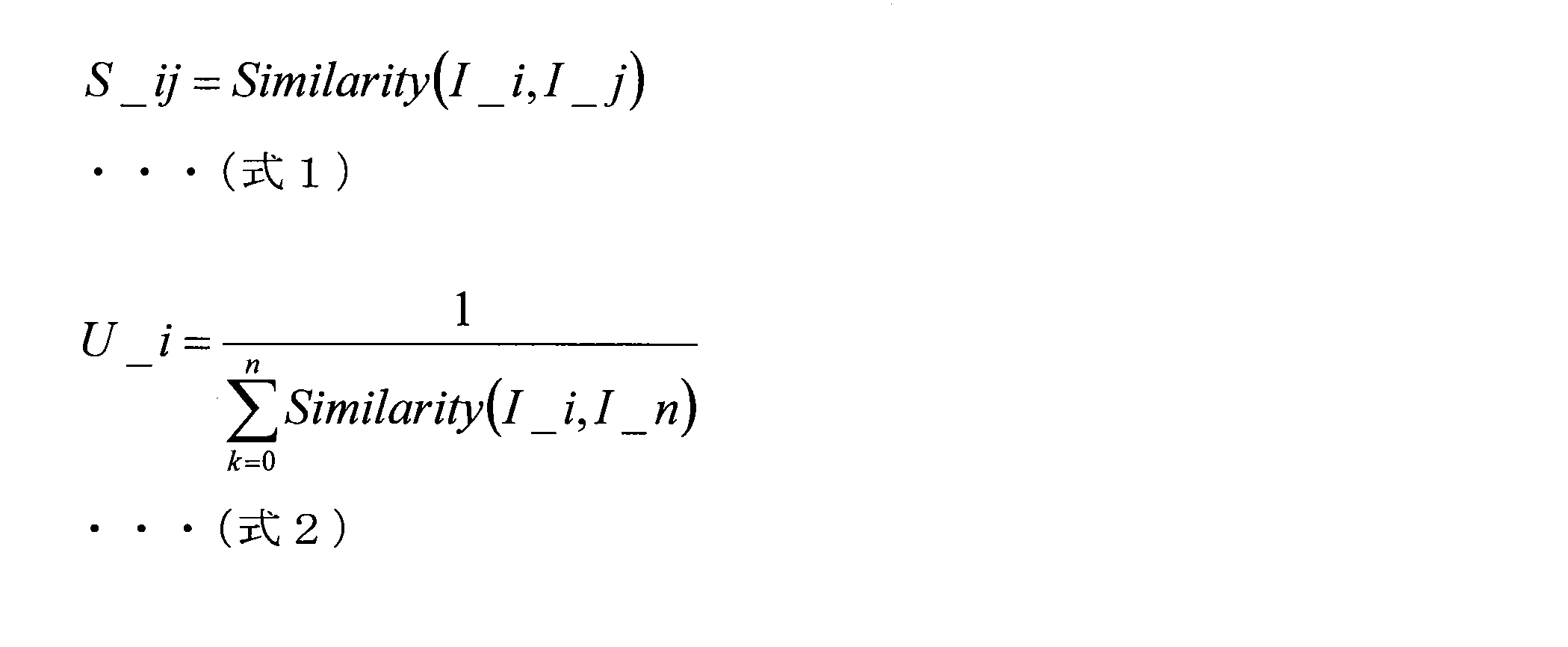
上記(式1)及び(式2)において、変数I_i及びI_jは、画像i及び画像jそれぞれの特徴量を示している。また、Similarity関数は、入力される情報(画像の特徴量)間の類似度を算出する関数に相当する。なお、画像間の類似度については、例えば、画像全体の特徴を表すBag of Words等のようなグローバル特徴量に基づき算出されてもよい。また、他の一例として、2つの画像間において局所特徴量のマッチングを行い、インライア数をカウントすることで、当該2つの画像間の類似度が算出されてもよい。
続いて、上記ユニークネススコアを利用した自己位置推定の一例について説明する。例えば、情報処理装置100は、各撮像部(例えば、メイン撮像部303及びサブ撮像部305)により撮像されたクエリ画像に類似する画像を、キーフレームとして登録されたキーフレーム画像から検索する。次いで、情報処理装置100は、各クエリ画像について検索されたキーフレーム画像のうち、より高いユニークネススコアを有するキーフレーム画像を特定する。そして、情報処理装置100は、特定した当該キーフレーム画像に対応するクエリ画像をクエリメイン画像として設定し、他のクエリ画像をクエリサブ画像として設定したうえで、姿勢パラメータの推定や、当該姿勢パラメータの推定結果の検証を行う。
以上のような制御により、変形例5に係る情報処理システムに依れば、よりユニークな特徴を有することが期待される画像を利用して自己位置推定を行うことが可能となり、当該自己位置推定の精度をより向上させることも可能となる。また、変形例5に係る情報処理システムに依れば、上述したような特性から、例えば、繰り返しパターンが撮像された画像のように類似するシーンが撮像された可能性のある画像が自己位置推定に利用される事態の発生を防止することも可能となる。
以上、変形例5として、自己位置推定の手法の一例として、各撮像部により撮像された画像それぞれについて当該画像にユニークな特徴に基づくスコアを算出し当該スコアを利用して自己位置推定を行う場合の一例について説明した。
(変形例6:サブ撮像部の選択に係る制御の一例)
続いて、変形例6として、サブ撮像部305が複数設定されている場合において、姿勢パラメータの推定結果の検証に利用するサブ撮像部305の選択に係る制御の一例について説明する。なお、変形例6では、移動体300が車両として構成されており、車両に搭載された撮像部を利用することで、当該車両の実空間上における位置や姿勢(即ち、姿勢パラメータ)を推定する場合の一例について説明する。
続いて、変形例6として、サブ撮像部305が複数設定されている場合において、姿勢パラメータの推定結果の検証に利用するサブ撮像部305の選択に係る制御の一例について説明する。なお、変形例6では、移動体300が車両として構成されており、車両に搭載された撮像部を利用することで、当該車両の実空間上における位置や姿勢(即ち、姿勢パラメータ)を推定する場合の一例について説明する。
例えば、都市部などの比較的視界の閉じた環境においては、車両の進行方向に向いた撮像部よりも、当該進行方向から左右に90度回転した方向(即ち、車両の左右方向)に向いた撮像部の方が、当該車両の移動に伴い撮像されるシーンの変化が大きい。即ち、車両の姿勢パラメータの変化量に対して画像として撮像されるシーンの変化量が、車両の進行方向に向いた撮像部に比べて、当該車両の左右方向を向いた撮像部の方がより大きくなることが予想される。そのため、例えば、車両に搭載された複数の撮像部のうち、当該車両の左右方向に向いた各撮像部を、メイン撮像部303及びサブ撮像部305として利用してもよい。具体的には、車両の左右方向のうち一方を向いた撮像部をメイン撮像部303として設定し、他方を向いた撮像部(即ち、メイン撮像部303と反対方向を向いた撮像部)をサブ撮像部305として設定するとよい。
以上のような制御により、変形例6に係る情報処理システム1に依れば、例えば、移動体300が車両として構成されているような状況下において、当該移動体300の姿勢パラメータの推定に係る精度や、当該推定結果の検証に係る精度をより向上させることが可能となる。
以上、変形例6として、サブ撮像部305が複数設定されている場合において、姿勢パラメータの推定結果の検証に利用するサブ撮像部305の選択に係る制御の一例について説明した。
(変形例7:サブ撮像部の選択に係る制御の一例)
続いて、変形例7として、図19を参照して、サブ撮像部305が複数設定されている場合において、姿勢パラメータの推定結果の検証に利用するサブ撮像部305の選択に係る制御の一例について説明する。図19は、変形例7に係る情報処理システムの概要について説明するための説明図である。
続いて、変形例7として、図19を参照して、サブ撮像部305が複数設定されている場合において、姿勢パラメータの推定結果の検証に利用するサブ撮像部305の選択に係る制御の一例について説明する。図19は、変形例7に係る情報処理システムの概要について説明するための説明図である。
撮像部により撮像された画像を利用した自己位置推定においては、データベース等に登録されている画像と、推定時に取得される画像と、の間においてある程度の共通視野が必要であり、一般的に共通視野が広いほど推定結果がロバストとなる。これは、サブ撮像部305を利用した姿勢パラメータの推定結果の検証にもあてはまる。本変形例では、このような状況を鑑みた、サブ撮像部305の選択方法の一例について説明する。なお、本実施形態では、前述したキーフレーム画像が、上記データベース等に登録されている画像に相当し、前述したクエリ画像が、上記推定時に取得される画像に相当する。また、図13を参照して説明した記憶部150が、上記データベース等に相当する。
前述したように、本開示の一実施形態に係る情報処理システム1では、メイン撮像部303により撮像されたメイン画像に基づき、当該メイン撮像部303(ひいては、移動体300)の姿勢パラメータの推定を行う。また、移動体300に保持される各撮像部の相対的な位置関係についてキャリブレーションが行われていれば、当該姿勢パラメータの推定結果に基づき、メイン撮像部303以外の他の撮像部(例えば、サブ撮像部305)の姿勢パラメータを推定(算出)することも可能である。
そこで、本変形例では、情報処理装置100は、複数のサブ撮像部305それぞれについて、キーフレームとして登録されている情報に基づく当該サブ撮像部305の姿勢を示す情報と、姿勢パラメータの推定の対象となっている当該サブ撮像部305の姿勢を示す情報と、を比較する。なお、以降の説明では、サブ撮像部305等の物体の姿勢を示す情報を、「回転パラメータ」とも称する。そして、情報処理装置100は、当該比較結果に基づき、複数のサブ撮像部305のうち、対応する回転パラメータから算出される撮像部の光軸方向ベクトルと、キーフレームとして登録されている情報に基づいて算出される撮像部の光軸方向ベクトルと、の角度差がより近い値を示すサブ撮像部305を選択する。
例えば、図19において、左側の図はキーフレームとして登録されている情報に応じた移動体300の姿勢を模式的に示している。また、右側の図は、姿勢パラメータの推定の対象となる移動体300の実際の姿勢を模式的に示している。なお、図19に示す例では、移動体300の筐体301に対して、メイン撮像部303と、複数のサブ撮像部305a及び305bと、が保持されている。また、メイン撮像部303、サブ撮像部305a、及びサブ撮像部305bのそれぞれは、移動体300を基準として互いに異なる方向を撮像するように保持されている。即ち、互いに異なる方向を撮像するように、撮像部の光軸方向ベクトルが設定されている。例えば、図19において、「main」として示した方向は、メイン撮像部303が画像を撮像する方向を示している。また、「sub1」として示した方向は、サブ撮像部305aが画像を撮像する方向を示している。また、「sub2」として示した方向は、サブ撮像部305bが画像を撮像する方向を示している。
即ち、図19に示す例の場合には、情報処理装置100は、サブ撮像部305a及び305bそれぞれについて、キーフレームとして登録されている情報に基づく当該撮像部の回転パラメータから算出される撮像部の光軸方向ベクトルと、姿勢パラメータの推定結果に応じて算出される当該撮像部の回転パラメータから算出される撮像部の光軸方向ベクトルと、の比較を行う。そして、情報処理装置100は、サブ撮像部305a及び305bとのうち、上記比較結果に応じて、姿勢パラメータの推定結果に応じた上記撮像部の光軸方向ベクトルと、キーフレームとして登録されている情報に基づく上記撮像部の光軸方向ベクトルと、の角度差がより近いサブ撮像部305を選択する。
例えば、図19に示す例では、サブ撮像部305aについては、キーフレームとして登録されている情報が示す撮像方向sub1が、移動体300の実際の姿勢に応じた撮像方向sub1と異なる。そのため、図19に示す例では、サブ撮像部305aについては、キーフレーム画像として撮像されたシーンとは異なるシーンが、クエリ画像として撮像されることとなる。そのため、サブ撮像部305aについては、キーフレーム画像とクエリ画像との間における共通視野がより狭くなる傾向にあり、ひいては、共通視野を有しない可能性もある。
これに対して、サブ撮像部305bについては、キーフレームとして登録されている情報が示す撮像方向sub2が、移動体300の実際の姿勢に応じた撮像方向sub2と略等しい。そのため、図19に示す例では、サブ撮像部305bについては、当該サブ撮像部305bの光軸を軸とした回転方向の違いを除けば、キーフレーム画像として撮像されたシーンと類似するシーンが、クエリ画像として撮像されることとなる。そのため、サブ撮像部305bについては、キーフレーム画像とクエリ画像との間における共通視野が、サブ撮像部305aの場合に比べてより広くなる。
即ち、図19に示す例では、情報処理装置100は、サブ撮像部305a及び305bのうち、キーフレーム画像とクエリ画像との間における共通視野がより広いサブ撮像部305bを選択することとなる。
特に、移動体300の回転に伴う各撮像部の視野の変化は、当該移動体300の並進に伴う当該撮像部の視野の変化に比べてより大きい傾向にある。そのため、変形例7に係る情報処理システムでは、このような特性を利用し、上述したように撮像方向(即ち、撮像部の光軸方向ベクトル)の比較により、キーフレーム画像とクエリ画像との間で共通視野がより広いサブ撮像部305を選択している。
以上のような制御により、変形例7に係る情報処理システム1に依れば、情報処理装置100は、複数のサブ撮像部305のうち、キーフレーム画像とクエリ画像との間で共通視野のより広い(即ち、視野の変化のより小さい)サブ撮像部305を選択することが可能となる。そのため、変形例7に係る情報処理システム1に依れば、移動体300の姿勢パラメータの推定結果の検証に係る精度をより向上させることが可能となる。
以上、変形例7として、図19を参照して、サブ撮像部305が複数設定されている場合において、姿勢パラメータの推定結果の検証に利用するサブ撮像部305の選択に係る制御の一例について説明した。
<<4.ハードウェア構成>>
続いて、図20を参照しながら、前述した情報処理装置100のように、本開示の一実施形態に係る情報処理システムを構成する情報処理装置のハードウェア構成の一例について、詳細に説明する。図20は、本開示の一実施形態に係る情報処理システムを構成する情報処理装置のハードウェア構成の一構成例を示す機能ブロック図である。
続いて、図20を参照しながら、前述した情報処理装置100のように、本開示の一実施形態に係る情報処理システムを構成する情報処理装置のハードウェア構成の一例について、詳細に説明する。図20は、本開示の一実施形態に係る情報処理システムを構成する情報処理装置のハードウェア構成の一構成例を示す機能ブロック図である。
本実施形態に係る情報処理システムを構成する情報処理装置900は、主に、CPU901と、ROM902と、RAM903と、を備える。また、情報処理装置900は、更に、ホストバス907と、ブリッジ909と、外部バス911と、インタフェース913と、入力装置915と、出力装置917と、ストレージ装置919と、ドライブ921と、接続ポート923と、通信装置925とを備える。
CPU901は、演算処理装置及び制御装置として機能し、ROM902、RAM903、ストレージ装置919又はリムーバブル記録媒体927に記録された各種プログラムに従って、情報処理装置900内の動作全般又はその一部を制御する。ROM902は、CPU901が使用するプログラムや演算パラメータ等を記憶する。RAM903は、CPU901が使用するプログラムや、プログラムの実行において適宜変化するパラメータ等を一次記憶する。これらはCPUバス等の内部バスにより構成されるホストバス907により相互に接続されている。例えば、図13に示す推定部101及び検証部103は、CPU901により構成され得る。
ホストバス907は、ブリッジ909を介して、PCI(Peripheral Component Interconnect/Interface)バスなどの外部バス911に接続されている。また、外部バス911には、インタフェース913を介して、入力装置915、出力装置917、ストレージ装置919、ドライブ921、接続ポート923及び通信装置925が接続される。
入力装置915は、例えば、マウス、キーボード、タッチパネル、ボタン、スイッチ、レバー及びペダル等、ユーザが操作する操作手段である。また、入力装置915は、例えば、赤外線やその他の電波を利用したリモートコントロール手段(いわゆる、リモコン)であってもよいし、情報処理装置900の操作に対応した携帯電話やPDA等の外部接続機器929であってもよい。さらに、入力装置915は、例えば、上記の操作手段を用いてユーザにより入力された情報に基づいて入力信号を生成し、CPU901に出力する入力制御回路などから構成されている。情報処理装置900のユーザは、この入力装置915を操作することにより、情報処理装置900に対して各種のデータを入力したり処理動作を指示したりすることができる。
出力装置917は、取得した情報をユーザに対して視覚的又は聴覚的に通知することが可能な装置で構成される。このような装置として、CRTディスプレイ装置、液晶ディスプレイ装置、プラズマディスプレイ装置、ELディスプレイ装置及びランプ等の表示装置や、スピーカ及びヘッドホン等の音声出力装置や、プリンタ装置等がある。出力装置917は、例えば、情報処理装置900が行った各種処理により得られた結果を出力する。具体的には、表示装置は、情報処理装置900が行った各種処理により得られた結果を、テキスト又はイメージで表示する。他方、音声出力装置は、再生された音声データや音響データ等からなるオーディオ信号をアナログ信号に変換して出力する。
ストレージ装置919は、情報処理装置900の記憶部の一例として構成されたデータ格納用の装置である。ストレージ装置919は、例えば、HDD(Hard Disk Drive)等の磁気記憶部デバイス、半導体記憶デバイス、光記憶デバイス又は光磁気記憶デバイス等により構成される。このストレージ装置919は、CPU901が実行するプログラムや各種データ等を格納する。例えば、図13に示す記憶部150は、ストレージ装置919により構成され得る。
ドライブ921は、記録媒体用リーダライタであり、情報処理装置900に内蔵、あるいは外付けされる。ドライブ921は、装着されている磁気ディスク、光ディスク、光磁気ディスク又は半導体メモリ等のリムーバブル記録媒体927に記録されている情報を読み出して、RAM903に出力する。また、ドライブ921は、装着されている磁気ディスク、光ディスク、光磁気ディスク又は半導体メモリ等のリムーバブル記録媒体927に記録を書き込むことも可能である。リムーバブル記録媒体927は、例えば、DVDメディア、HD-DVDメディア又はBlu-ray(登録商標)メディア等である。また、リムーバブル記録媒体927は、コンパクトフラッシュ(登録商標)(CF:CompactFlash)、フラッシュメモリ又はSDメモリカード(Secure Digital memory card)等であってもよい。また、リムーバブル記録媒体927は、例えば、非接触型ICチップを搭載したICカード(Integrated Circuit card)又は電子機器等であってもよい。
接続ポート923は、情報処理装置900に直接接続するためのポートである。接続ポート923の一例として、USB(Universal Serial Bus)ポート、IEEE1394ポート、SCSI(Small Computer System Interface)ポート等がある。接続ポート923の別の例として、RS-232Cポート、光オーディオ端子、HDMI(登録商標)(High-Definition Multimedia Interface)ポート等がある。この接続ポート923に外部接続機器929を接続することで、情報処理装置900は、外部接続機器929から直接各種のデータを取得したり、外部接続機器929に各種のデータを提供したりする。
通信装置925は、例えば、通信網(ネットワーク)931に接続するための通信デバイス等で構成された通信インタフェースである。通信装置925は、例えば、有線若しくは無線LAN(Local Area Network)、Bluetooth(登録商標)又はWUSB(Wireless USB)用の通信カード等である。また、通信装置925は、光通信用のルータ、ADSL(Asymmetric Digital Subscriber Line)用のルータ又は各種通信用のモデム等であってもよい。この通信装置925は、例えば、インターネットや他の通信機器との間で、例えばTCP/IP等の所定のプロトコルに則して信号等を送受信することができる。また、通信装置925に接続される通信網931は、有線又は無線によって接続されたネットワーク等により構成され、例えば、インターネット、家庭内LAN、赤外線通信、ラジオ波通信又は衛星通信等であってもよい。
以上、本開示の実施形態に係る情報処理システムを構成する情報処理装置900の機能を実現可能なハードウェア構成の一例を示した。上記の各構成要素は、汎用的な部材を用いて構成されていてもよいし、各構成要素の機能に特化したハードウェアにより構成されていてもよい。従って、本実施形態を実施する時々の技術レベルに応じて、適宜、利用するハードウェア構成を変更することが可能である。なお、図20では図示しないが、情報処理システムを構成する情報処理装置900に対応する各種の構成を当然備える。
なお、上述のような本実施形態に係る情報処理システムを構成する情報処理装置900の各機能を実現するためのコンピュータプログラムを作製し、パーソナルコンピュータ等に実装することが可能である。また、このようなコンピュータプログラムが格納された、コンピュータで読み取り可能な記録媒体も提供することができる。記録媒体は、例えば、磁気ディスク、光ディスク、光磁気ディスク、フラッシュメモリなどである。また、上記のコンピュータプログラムは、記録媒体を用いずに、例えばネットワークを介して配信してもよい。また、当該コンピュータプログラムを実行させるコンピュータの数は特に限定されない。例えば、当該コンピュータプログラムを、複数のコンピュータ(例えば、複数のサーバ等)が互いに連携して実行してもよい。
<<5.むすび>>
以上説明したように、本実施形態に係る情報処理システム1では、姿勢パラメータの推定の対象となる移動体300の筐体301には、メイン撮像部303及びサブ撮像部305が、互いに異なる光軸を有するように保持される。このような構成の基で、情報処理装置100は、メイン撮像部303により撮像されたメイン画像に基づき、移動体300の実空間上における位置や姿勢(即ち、姿勢パラメータ)を推定する。また、情報処理装置100は、サブ撮像部305により撮像されたサブ画像に基づき、上記移動体300の位置や姿勢の推定結果の確からしさを検証する。
以上説明したように、本実施形態に係る情報処理システム1では、姿勢パラメータの推定の対象となる移動体300の筐体301には、メイン撮像部303及びサブ撮像部305が、互いに異なる光軸を有するように保持される。このような構成の基で、情報処理装置100は、メイン撮像部303により撮像されたメイン画像に基づき、移動体300の実空間上における位置や姿勢(即ち、姿勢パラメータ)を推定する。また、情報処理装置100は、サブ撮像部305により撮像されたサブ画像に基づき、上記移動体300の位置や姿勢の推定結果の確からしさを検証する。
以上のような構成により、本実施形態に係る情報処理システム1に依れば、移動体300の実空間上における位置や姿勢の推定に係る精度をより向上させることが可能となり、ひいては、当該位置や当該姿勢の誤推定を防止することが可能となる。
なお、メイン撮像部303が、「第1の撮像部」の一例に相当し、当該メイン撮像部303により撮像されたメイン画像が、「第1の画像」の一例に相当する。また、サブ撮像部305が、「第2の撮像部」の一例に相当し、当該サブ撮像部305により撮像されたサブ画像が、「第2の画像」の一例に相当する。
また、上述した実施形態や各変形例については、適宜組み合わせて利用することも可能である。具体的な一例として、メイン撮像部303及びサブ撮像部305のそれぞれが複数設定されている場合には、変形例2及び3それぞれで説明した技術を組み合わせて利用することも可能である。
以上、添付図面を参照しながら本開示の好適な実施形態について詳細に説明したが、本開示の技術的範囲はかかる例に限定されない。本開示の技術分野における通常の知識を有する者であれば、特許請求の範囲に記載された技術的思想の範疇内において、各種の変更例または修正例に想到し得ることは明らかであり、これらについても、当然に本開示の技術的範囲に属するものと了解される。
また、本明細書に記載された効果は、あくまで説明的または例示的なものであって限定的ではない。つまり、本開示に係る技術は、上記の効果とともに、または上記の効果に代えて、本明細書の記載から当業者には明らかな他の効果を奏しうる。
なお、以下のような構成も本開示の技術的範囲に属する。
(1)
所定の筐体に保持された複数の撮像部のうち第1の撮像部により撮像された第1の画像に基づき、前記筐体の実空間上における位置及び姿勢のうち少なくともいずれかを推定する推定部と、
前記複数の撮像部のうち前記第1の撮像部とは光軸が異なる第2の撮像部により撮像された第2の画像に基づき、前記推定結果の確からしさを検証する検証部と、
を備える、情報処理装置。
(2)
前記検証部は、前記第2の画像から抽出される第1の特徴量と、前記筐体の実空間上における位置及び姿勢のうち少なくともいずれかに関連付けてあらかじめ記録された第2の特徴量と、を比較することで、前記推定結果の確からしさを検証する、前記(1)に記載の情報処理装置。
(3)
前記第2の特徴量は、前記筐体の実空間上における位置及び姿勢のうち少なくともいずれかに応じて、前記第2の撮像部により撮像される前記第2の画像に基づき取得される、前記(2)に記載の情報処理装置。
(4)
前記検証部は、前記推定結果の検証に利用する前記第2の画像から前記第1の特徴量として抽出される1以上の特徴点それぞれに対応する特徴量と、前記第2の特徴量として記録された1以上の特徴点それぞれに対応する特徴量と、を比較することで、前記推定結果の確からしさを検証する、前記(3)に記載の情報処理装置。
(5)
前記検証部は、前記推定結果の検証に利用する前記第2の画像から前記第1の特徴量として抽出される前記特徴点を含む部分領域の特徴量と、前記第2の特徴量として記録された前記特徴点を含む部分領域の特徴量と、を比較することで、前記推定結果の確からしさを検証する、前記(4)に記載の情報処理装置。
(6)
前記検証部は、前記推定結果の検証に利用する前記第2の画像から前記第1の特徴量として抽出される1以上の前記特徴点それぞれについて、当該特徴点を含む前記部分領域と、前記第2の特徴量として記録された1以上の前記特徴点のうち対応する前記特徴点を含む前記部分領域と、間の類似度を算出し、当該類似度の算出結果が閾値以上となる前記特徴点の数に応じて、前記推定結果の確からしさを検証する、前記(5)に記載の情報処理装置。
(7)
前記複数の撮像部のうち、2以上の撮像部が前記第2の撮像部の候補として設定されており、
前記第2の特徴量は、抽出元となる前記第2の画像が撮像されたときの前記第2の撮像部の実空間上の姿勢に応じたパラメータと関連付けられており、
前記推定部は、前記第1の画像に基づき、複数の前記第2の撮像部の候補それぞれの前記パラメータを取得し、
前記検証部は、複数の前記第2の撮像部の候補それぞれについて取得された前記パラメータと、前記第2の特徴量に関連付けられた前記パラメータと、に基づき、少なくとも一部の当該候補を選択し、選択した当該候補により撮像された前記第2の画像に基づき、前記推定結果の確からしさを検証する、
前記(3)~(6)のいずれか一項に記載の情報処理装置。
(8)
前記検証部は、前記筐体の実空間上における位置及び姿勢のうち少なくともいずれかごとに前記第2の撮像部により撮像された前記第2の画像に基づく機械学習に応じて生成された判別器により、前記推定結果の確からしさを検証する、前記(1)に記載の情報処理装置。
(9)
前記検証部は、前記推定結果の検証に利用する前記第2の画像と、過去に撮像された前記第2の画像と、の間の類似度に応じて、当該推定結果の確からしさを検証する、前記(1)に記載の情報処理装置。
(10)
前記複数の撮像部のうち、2以上の撮像部が前記第2の撮像部として設定されており、
前記検証部は、2以上の前記第2の撮像部それぞれにより撮像された前記第2の画像に基づき、前記推定結果の確からしさを検証する、
前記(1)~(9)のいずれか一項に記載の情報処理装置。
(11)
前記推定部は、前記検証結果に応じて、前記複数の撮像部から新たな第1の撮像部を選択し、当該新たな第1の撮像部により撮像された新たな第1の画像に基づき、前記筐体の実空間上における位置及び姿勢のうち少なくともいずれかを再度推定する、前記(1)~(10)のいずれか一項に記載の情報処理装置。
(12)
前記推定部は、前記検証結果に応じて、前記複数の撮像部のうち第1の撮像部の候補として設定された2以上の撮像部の中から、前記新たな第1の撮像部を選択する、前記(11)に記載の情報処理装置。
(13)
前記推定部は、前記検証結果に応じて、前記第2の撮像部を前記新たな第1の撮像部として選択し、
前記検証部は、当該選択前の前記第1の撮像部を新たな第2の撮像部として選択し、当該新たな第2の撮像部により撮像された新たな第2の画像に基づき、前記新たな第1の画像に基づく前記推定結果を検証する、
前記(11)に記載の情報処理装置。
(14)
前記筐体は、移動体の筐体であり、
前記推定部は、前記移動体の進行方向とは異なる方向を撮像する前記第1の撮像部により撮像された前記第1の画像に基づき、前記筐体の実空間上における位置及び姿勢のうち少なくともいずれかを推定する
前記(1)~(13)のいずれか一項に記載の情報処理装置。
(15)
前記検証部は、前記第1の撮像部とは反対の方向を撮像する前記第2の撮像部により撮像された前記第2の画像に基づき、前記推定結果の確からしさを検証する、前記(1)~(14)のいずれか一項に記載の情報処理装置。
(16)
コンピュータが、
所定の筐体に保持された複数の撮像部のうち第1の撮像部により撮像された第1の画像に基づき、前記筐体の実空間上における位置及び姿勢のうち少なくともいずれかを推定することと、
前記複数の撮像部のうち前記第1の撮像部とは光軸が異なる第2の撮像部により撮像された第2の画像に基づき、前記推定結果の確からしさを検証することと、
を含む、情報処理方法。
(17)
コンピュータに、
所定の筐体に保持された複数の撮像部のうち第1の撮像部により撮像された第1の画像に基づき、前記筐体の実空間上における位置及び姿勢のうち少なくともいずれかを推定することと、
前記複数の撮像部のうち前記第1の撮像部とは光軸が異なる第2の撮像部により撮像された第2の画像に基づき、前記推定結果の確からしさを検証することと、
を実行させる、プログラム。
1 情報処理システム
100 情報処理装置
101 推定部
103 検証部
150 記憶部
300 移動体
301 筐体
303 メイン撮像部
305 サブ撮像部
100 情報処理装置
101 推定部
103 検証部
150 記憶部
300 移動体
301 筐体
303 メイン撮像部
305 サブ撮像部
Claims (17)
- 所定の筐体に保持された複数の撮像部のうち第1の撮像部により撮像された第1の画像に基づき、前記筐体の実空間上における位置及び姿勢のうち少なくともいずれかを推定する推定部と、
前記複数の撮像部のうち前記第1の撮像部とは光軸が異なる第2の撮像部により撮像された第2の画像に基づき、前記推定結果の確からしさを検証する検証部と、
を備える、情報処理装置。 - 前記検証部は、前記第2の画像から抽出される第1の特徴量と、前記筐体の実空間上における位置及び姿勢のうち少なくともいずれかに関連付けてあらかじめ記録された第2の特徴量と、を比較することで、前記推定結果の確からしさを検証する、請求項1に記載の情報処理装置。
- 前記第2の特徴量は、前記筐体の実空間上における位置及び姿勢のうち少なくともいずれかに応じて、前記第2の撮像部により撮像される前記第2の画像に基づき取得される、請求項2に記載の情報処理装置。
- 前記検証部は、前記推定結果の検証に利用する前記第2の画像から前記第1の特徴量として抽出される1以上の特徴点それぞれに対応する特徴量と、前記第2の特徴量として記録された1以上の特徴点それぞれに対応する特徴量と、を比較することで、前記推定結果の確からしさを検証する、請求項3に記載の情報処理装置。
- 前記検証部は、前記推定結果の検証に利用する前記第2の画像から前記第1の特徴量として抽出される前記特徴点を含む部分領域の特徴量と、前記第2の特徴量として記録された前記特徴点を含む部分領域の特徴量と、を比較することで、前記推定結果の確からしさを検証する、請求項4に記載の情報処理装置。
- 前記検証部は、前記推定結果の検証に利用する前記第2の画像から前記第1の特徴量として抽出される1以上の前記特徴点それぞれについて、当該特徴点を含む前記部分領域と、前記第2の特徴量として記録された1以上の前記特徴点のうち対応する前記特徴点を含む前記部分領域と、間の類似度を算出し、当該類似度の算出結果が閾値以上となる前記特徴点の数に応じて、前記推定結果の確からしさを検証する、請求項5に記載の情報処理装置。
- 前記複数の撮像部のうち、2以上の撮像部が前記第2の撮像部の候補として設定されており、
前記第2の特徴量は、抽出元となる前記第2の画像が撮像されたときの前記第2の撮像部の実空間上の姿勢に応じたパラメータと関連付けられており、
前記推定部は、前記第1の画像に基づき、複数の前記第2の撮像部の候補それぞれの前記パラメータを取得し、
前記検証部は、複数の前記第2の撮像部の候補それぞれについて取得された前記パラメータと、前記第2の特徴量に関連付けられた前記パラメータと、に基づき、少なくとも一部の当該候補を選択し、選択した当該候補により撮像された前記第2の画像に基づき、前記推定結果の確からしさを検証する、
請求項3に記載の情報処理装置。 - 前記検証部は、前記筐体の実空間上における位置及び姿勢のうち少なくともいずれかごとに前記第2の撮像部により撮像された前記第2の画像に基づく機械学習に応じて生成された判別器により、前記推定結果の確からしさを検証する、請求項1に記載の情報処理装置。
- 前記検証部は、前記推定結果の検証に利用する前記第2の画像と、過去に撮像された前記第2の画像と、の間の類似度に応じて、当該推定結果の確からしさを検証する、請求項1に記載の情報処理装置。
- 前記複数の撮像部のうち、2以上の撮像部が前記第2の撮像部として設定されており、
前記検証部は、2以上の前記第2の撮像部それぞれにより撮像された前記第2の画像に基づき、前記推定結果の確からしさを検証する、
請求項1に記載の情報処理装置。 - 前記推定部は、前記検証結果に応じて、前記複数の撮像部から新たな第1の撮像部を選択し、当該新たな第1の撮像部により撮像された新たな第1の画像に基づき、前記筐体の実空間上における位置及び姿勢のうち少なくともいずれかを再度推定する、請求項1に記載の情報処理装置。
- 前記推定部は、前記検証結果に応じて、前記複数の撮像部のうち第1の撮像部の候補として設定された2以上の撮像部の中から、前記新たな第1の撮像部を選択する、請求項11に記載の情報処理装置。
- 前記推定部は、前記検証結果に応じて、前記第2の撮像部を前記新たな第1の撮像部として選択し、
前記検証部は、当該選択前の前記第1の撮像部を新たな第2の撮像部として選択し、当該新たな第2の撮像部により撮像された新たな第2の画像に基づき、前記新たな第1の画像に基づく前記推定結果を検証する、
請求項11に記載の情報処理装置。 - 前記筐体は、移動体の筐体であり、
前記推定部は、前記移動体の進行方向とは異なる方向を撮像する前記第1の撮像部により撮像された前記第1の画像に基づき、前記筐体の実空間上における位置及び姿勢のうち少なくともいずれかを推定する
請求項1に記載の情報処理装置。 - 前記検証部は、前記第1の撮像部とは反対の方向を撮像する前記第2の撮像部により撮像された前記第2の画像に基づき、前記推定結果の確からしさを検証する、請求項1に記載の情報処理装置。
- コンピュータが、
所定の筐体に保持された複数の撮像部のうち第1の撮像部により撮像された第1の画像に基づき、前記筐体の実空間上における位置及び姿勢のうち少なくともいずれかを推定することと、
前記複数の撮像部のうち前記第1の撮像部とは光軸が異なる第2の撮像部により撮像された第2の画像に基づき、前記推定結果の確からしさを検証することと、
を含む、情報処理方法。 - コンピュータに、
所定の筐体に保持された複数の撮像部のうち第1の撮像部により撮像された第1の画像に基づき、前記筐体の実空間上における位置及び姿勢のうち少なくともいずれかを推定することと、
前記複数の撮像部のうち前記第1の撮像部とは光軸が異なる第2の撮像部により撮像された第2の画像に基づき、前記推定結果の確からしさを検証することと、
を実行させる、プログラム。
Priority Applications (5)
| Application Number | Priority Date | Filing Date | Title |
|---|---|---|---|
| JP2019516898A JP7147753B2 (ja) | 2017-05-09 | 2018-02-21 | 情報処理装置、情報処理方法、及びプログラム |
| US16/485,932 US11263777B2 (en) | 2017-05-09 | 2018-02-21 | Information processing apparatus and information processing method |
| EP18798388.7A EP3624060A4 (en) | 2017-05-09 | 2018-02-21 | INFORMATION PROCESSING DEVICE, INFORMATION PROCESSING PROCESS AND PROGRAM |
| CN201880012177.XA CN110337671A (zh) | 2017-05-09 | 2018-02-21 | 信息处理装置、信息处理方法和程序 |
| US17/588,749 US20220156973A1 (en) | 2017-05-09 | 2022-01-31 | Information processing apparatus, information processing method, and program |
Applications Claiming Priority (2)
| Application Number | Priority Date | Filing Date | Title |
|---|---|---|---|
| JP2017092793 | 2017-05-09 | ||
| JP2017-092793 | 2017-05-09 |
Related Child Applications (2)
| Application Number | Title | Priority Date | Filing Date |
|---|---|---|---|
| US16/485,932 A-371-Of-International US11263777B2 (en) | 2017-05-09 | 2018-02-21 | Information processing apparatus and information processing method |
| US17/588,749 Continuation US20220156973A1 (en) | 2017-05-09 | 2022-01-31 | Information processing apparatus, information processing method, and program |
Publications (1)
| Publication Number | Publication Date |
|---|---|
| WO2018207426A1 true WO2018207426A1 (ja) | 2018-11-15 |
Family
ID=64105447
Family Applications (1)
| Application Number | Title | Priority Date | Filing Date |
|---|---|---|---|
| PCT/JP2018/006254 Ceased WO2018207426A1 (ja) | 2017-05-09 | 2018-02-21 | 情報処理装置、情報処理方法、及びプログラム |
Country Status (5)
| Country | Link |
|---|---|
| US (2) | US11263777B2 (ja) |
| EP (1) | EP3624060A4 (ja) |
| JP (1) | JP7147753B2 (ja) |
| CN (1) | CN110337671A (ja) |
| WO (1) | WO2018207426A1 (ja) |
Cited By (7)
| Publication number | Priority date | Publication date | Assignee | Title |
|---|---|---|---|---|
| CN111489393A (zh) * | 2019-01-28 | 2020-08-04 | 速感科技(北京)有限公司 | Vslam方法、控制器和可移动设备 |
| WO2021117552A1 (ja) * | 2019-12-10 | 2021-06-17 | ソニーグループ株式会社 | 情報処理システム、情報処理方法、及びプログラム |
| JP2022523312A (ja) * | 2019-01-28 | 2022-04-22 | キューフィールテック (ベイジン) カンパニー,リミティド | Vslam方法、コントローラ及び移動可能機器 |
| US11629965B2 (en) | 2019-01-28 | 2023-04-18 | Qfeeltech (Beijing) Co., Ltd. | Methods, apparatus, and systems for localization and mapping |
| WO2024042644A1 (ja) * | 2022-08-24 | 2024-02-29 | 日本電信電話株式会社 | 映像処理装置、映像処理方法、および映像処理プログラム |
| JPWO2024042645A1 (ja) * | 2022-08-24 | 2024-02-29 | ||
| WO2025258356A1 (ja) * | 2024-06-14 | 2025-12-18 | パナソニックIpマネジメント株式会社 | 情報処理方法及び装置 |
Families Citing this family (1)
| Publication number | Priority date | Publication date | Assignee | Title |
|---|---|---|---|---|
| JP7689308B2 (ja) * | 2020-02-07 | 2025-06-06 | パナソニックIpマネジメント株式会社 | 測位システム |
Citations (3)
| Publication number | Priority date | Publication date | Assignee | Title |
|---|---|---|---|---|
| JP2004005593A (ja) | 2002-04-17 | 2004-01-08 | Matsushita Electric Works Ltd | 自律移動装置 |
| JP2008070267A (ja) * | 2006-09-14 | 2008-03-27 | Canon Inc | 位置姿勢計測方法及び装置 |
| JP2012022411A (ja) * | 2010-07-12 | 2012-02-02 | Canon Inc | 情報処理装置及びその制御方法、プログラム |
Family Cites Families (5)
| Publication number | Priority date | Publication date | Assignee | Title |
|---|---|---|---|---|
| US6064749A (en) * | 1996-08-02 | 2000-05-16 | Hirota; Gentaro | Hybrid tracking for augmented reality using both camera motion detection and landmark tracking |
| GB2411532B (en) * | 2004-02-11 | 2010-04-28 | British Broadcasting Corp | Position determination |
| JP4966542B2 (ja) * | 2005-12-22 | 2012-07-04 | 株式会社トプコン | 位置データ補間方法及び位置測定装置 |
| US9280804B2 (en) * | 2012-11-16 | 2016-03-08 | Google Inc. | Rotation of an image based on image content to correct image orientation |
| US9165371B2 (en) * | 2012-12-24 | 2015-10-20 | Harman International Industries, Incorporated | User location system |
-
2018
- 2018-02-21 US US16/485,932 patent/US11263777B2/en not_active Expired - Fee Related
- 2018-02-21 JP JP2019516898A patent/JP7147753B2/ja active Active
- 2018-02-21 CN CN201880012177.XA patent/CN110337671A/zh not_active Withdrawn
- 2018-02-21 WO PCT/JP2018/006254 patent/WO2018207426A1/ja not_active Ceased
- 2018-02-21 EP EP18798388.7A patent/EP3624060A4/en not_active Withdrawn
-
2022
- 2022-01-31 US US17/588,749 patent/US20220156973A1/en not_active Abandoned
Patent Citations (3)
| Publication number | Priority date | Publication date | Assignee | Title |
|---|---|---|---|---|
| JP2004005593A (ja) | 2002-04-17 | 2004-01-08 | Matsushita Electric Works Ltd | 自律移動装置 |
| JP2008070267A (ja) * | 2006-09-14 | 2008-03-27 | Canon Inc | 位置姿勢計測方法及び装置 |
| JP2012022411A (ja) * | 2010-07-12 | 2012-02-02 | Canon Inc | 情報処理装置及びその制御方法、プログラム |
Non-Patent Citations (1)
| Title |
|---|
| See also references of EP3624060A4 |
Cited By (15)
| Publication number | Priority date | Publication date | Assignee | Title |
|---|---|---|---|---|
| JP2022523312A (ja) * | 2019-01-28 | 2022-04-22 | キューフィールテック (ベイジン) カンパニー,リミティド | Vslam方法、コントローラ及び移動可能機器 |
| US11629965B2 (en) | 2019-01-28 | 2023-04-18 | Qfeeltech (Beijing) Co., Ltd. | Methods, apparatus, and systems for localization and mapping |
| CN111489393A (zh) * | 2019-01-28 | 2020-08-04 | 速感科技(北京)有限公司 | Vslam方法、控制器和可移动设备 |
| US12062147B2 (en) | 2019-12-10 | 2024-08-13 | Sony Group Corporation | Information processing system and information processing method |
| WO2021117552A1 (ja) * | 2019-12-10 | 2021-06-17 | ソニーグループ株式会社 | 情報処理システム、情報処理方法、及びプログラム |
| JPWO2021117552A1 (ja) * | 2019-12-10 | 2021-06-17 | ||
| CN114762007A (zh) * | 2019-12-10 | 2022-07-15 | 索尼集团公司 | 信息处理系统、信息处理方法和程序 |
| JP7613375B2 (ja) | 2019-12-10 | 2025-01-15 | ソニーグループ株式会社 | 情報処理システム、情報処理方法、及びプログラム |
| WO2024042644A1 (ja) * | 2022-08-24 | 2024-02-29 | 日本電信電話株式会社 | 映像処理装置、映像処理方法、および映像処理プログラム |
| WO2024042645A1 (ja) * | 2022-08-24 | 2024-02-29 | 日本電信電話株式会社 | 映像処理装置、映像処理方法、および映像処理プログラム |
| JPWO2024042644A1 (ja) * | 2022-08-24 | 2024-02-29 | ||
| JPWO2024042645A1 (ja) * | 2022-08-24 | 2024-02-29 | ||
| JP7740563B2 (ja) | 2022-08-24 | 2025-09-17 | Ntt株式会社 | 映像処理装置、映像処理方法、および映像処理プログラム |
| JP7803422B2 (ja) | 2022-08-24 | 2026-01-21 | Ntt株式会社 | 映像処理装置、映像処理方法、および映像処理プログラム |
| WO2025258356A1 (ja) * | 2024-06-14 | 2025-12-18 | パナソニックIpマネジメント株式会社 | 情報処理方法及び装置 |
Also Published As
| Publication number | Publication date |
|---|---|
| EP3624060A1 (en) | 2020-03-18 |
| US20220156973A1 (en) | 2022-05-19 |
| US20200126254A1 (en) | 2020-04-23 |
| JP7147753B2 (ja) | 2022-10-05 |
| JPWO2018207426A1 (ja) | 2020-03-12 |
| US11263777B2 (en) | 2022-03-01 |
| CN110337671A (zh) | 2019-10-15 |
| EP3624060A4 (en) | 2020-03-25 |
Similar Documents
| Publication | Publication Date | Title |
|---|---|---|
| JP7147753B2 (ja) | 情報処理装置、情報処理方法、及びプログラム | |
| CN110411441B (zh) | 用于多模态映射和定位的系统和方法 | |
| US9501725B2 (en) | Interactive and automatic 3-D object scanning method for the purpose of database creation | |
| US10096129B2 (en) | Three-dimensional mapping of an environment | |
| CN110555901B (zh) | 动静态场景的定位和建图方法、装置、设备和存储介质 | |
| JP6430064B2 (ja) | データを位置合わせする方法及びシステム | |
| EP3420530B1 (en) | A device and method for determining a pose of a camera | |
| CN107025662B (zh) | 一种实现增强现实的方法、服务器、终端及系统 | |
| Rambach et al. | Learning to fuse: A deep learning approach to visual-inertial camera pose estimation | |
| KR101072876B1 (ko) | 이동 로봇에서 자신의 위치를 추정하기 위한 방법 및 장치 | |
| CN110322500A (zh) | 即时定位与地图构建的优化方法及装置、介质和电子设备 | |
| CN107735797A (zh) | 用于确定第一坐标系与第二坐标系之间的运动的方法 | |
| CN114120301B (zh) | 一种位姿确定方法、装置及设备 | |
| CN112731503A (zh) | 一种基于前端紧耦合的位姿估计方法及系统 | |
| CN110827353A (zh) | 一种基于单目摄像头辅助的机器人定位方法 | |
| TW201830336A (zh) | 位置姿勢推定裝置以及位置姿勢推定方法 | |
| CN120252680A (zh) | 一种基于多传感器融合的slam定位方法及系统 | |
| KR20220062709A (ko) | 모바일 디바이스 영상에 기반한 공간 정보 클러스터링에 의한 재난 상황 인지 시스템 및 방법 | |
| KR102249380B1 (ko) | 기준 영상 정보를 이용한 cctv 장치의 공간 정보 생성 시스템 | |
| Han et al. | Uav vision: Feature based accurate ground target localization through propagated initializations and interframe homographies | |
| Baligh Jahromi et al. | Layout slam with model based loop closure for 3d indoor corridor reconstruction | |
| WO2020137314A1 (ja) | 位置測定装置 | |
| Sasiadek et al. | Accurate feature matching for autonomous vehicle navigation in urban environments | |
| CN118552944A (zh) | 一种车位号识别方法及装置、设备、存储介质 | |
| Baligh Jahromi et al. | a Preliminary Work on Layout Slam for Reconstruction of Indoor Corridor Environments |
Legal Events
| Date | Code | Title | Description |
|---|---|---|---|
| 121 | Ep: the epo has been informed by wipo that ep was designated in this application |
Ref document number: 18798388 Country of ref document: EP Kind code of ref document: A1 |
|
| ENP | Entry into the national phase |
Ref document number: 2019516898 Country of ref document: JP Kind code of ref document: A |
|
| NENP | Non-entry into the national phase |
Ref country code: DE |
|
| ENP | Entry into the national phase |
Ref document number: 2018798388 Country of ref document: EP Effective date: 20191209 |