WO2018207911A1 - 電池包装体 - Google Patents
電池包装体 Download PDFInfo
- Publication number
- WO2018207911A1 WO2018207911A1 PCT/JP2018/018317 JP2018018317W WO2018207911A1 WO 2018207911 A1 WO2018207911 A1 WO 2018207911A1 JP 2018018317 W JP2018018317 W JP 2018018317W WO 2018207911 A1 WO2018207911 A1 WO 2018207911A1
- Authority
- WO
- WIPO (PCT)
- Prior art keywords
- battery
- rib
- fixed
- battery package
- storage
- Prior art date
- Legal status (The legal status is an assumption and is not a legal conclusion. Google has not performed a legal analysis and makes no representation as to the accuracy of the status listed.)
- Ceased
Links
Images


Classifications
-
- B—PERFORMING OPERATIONS; TRANSPORTING
- B65—CONVEYING; PACKING; STORING; HANDLING THIN OR FILAMENTARY MATERIAL
- B65D—CONTAINERS FOR STORAGE OR TRANSPORT OF ARTICLES OR MATERIALS, e.g. BAGS, BARRELS, BOTTLES, BOXES, CANS, CARTONS, CRATES, DRUMS, JARS, TANKS, HOPPERS, FORWARDING CONTAINERS; ACCESSORIES, CLOSURES, OR FITTINGS THEREFOR; PACKAGING ELEMENTS; PACKAGES
- B65D75/00—Packages comprising articles or materials partially or wholly enclosed in strips, sheets, blanks, tubes or webs of flexible sheet material, e.g. in folded wrappers
- B65D75/28—Articles or materials wholly enclosed in composite wrappers, i.e. wrappers formed by associating or interconnecting two or more sheets or blanks
- B65D75/30—Articles or materials enclosed between two opposed sheets or blanks having their margins united, e.g. by pressure-sensitive adhesive, crimping, heat-sealing, or welding
- B65D75/32—Articles or materials enclosed between two opposed sheets or blanks having their margins united, e.g. by pressure-sensitive adhesive, crimping, heat-sealing, or welding one or both sheets or blanks being recessed to accommodate contents
- B65D75/36—Articles or materials enclosed between two opposed sheets or blanks having their margins united, e.g. by pressure-sensitive adhesive, crimping, heat-sealing, or welding one or both sheets or blanks being recessed to accommodate contents one sheet or blank being recessed and the other formed of relatively stiff flat sheet material, e.g. blister packages, the recess or recesses being preformed
- B65D75/366—Articles or materials enclosed between two opposed sheets or blanks having their margins united, e.g. by pressure-sensitive adhesive, crimping, heat-sealing, or welding one or both sheets or blanks being recessed to accommodate contents one sheet or blank being recessed and the other formed of relatively stiff flat sheet material, e.g. blister packages, the recess or recesses being preformed and forming one compartment
-
- B—PERFORMING OPERATIONS; TRANSPORTING
- B65—CONVEYING; PACKING; STORING; HANDLING THIN OR FILAMENTARY MATERIAL
- B65D—CONTAINERS FOR STORAGE OR TRANSPORT OF ARTICLES OR MATERIALS, e.g. BAGS, BARRELS, BOTTLES, BOXES, CANS, CARTONS, CRATES, DRUMS, JARS, TANKS, HOPPERS, FORWARDING CONTAINERS; ACCESSORIES, CLOSURES, OR FITTINGS THEREFOR; PACKAGING ELEMENTS; PACKAGES
- B65D75/00—Packages comprising articles or materials partially or wholly enclosed in strips, sheets, blanks, tubes or webs of flexible sheet material, e.g. in folded wrappers
- B65D75/28—Articles or materials wholly enclosed in composite wrappers, i.e. wrappers formed by associating or interconnecting two or more sheets or blanks
- B65D75/30—Articles or materials enclosed between two opposed sheets or blanks having their margins united, e.g. by pressure-sensitive adhesive, crimping, heat-sealing, or welding
- B65D75/32—Articles or materials enclosed between two opposed sheets or blanks having their margins united, e.g. by pressure-sensitive adhesive, crimping, heat-sealing, or welding one or both sheets or blanks being recessed to accommodate contents
- B65D75/36—Articles or materials enclosed between two opposed sheets or blanks having their margins united, e.g. by pressure-sensitive adhesive, crimping, heat-sealing, or welding one or both sheets or blanks being recessed to accommodate contents one sheet or blank being recessed and the other formed of relatively stiff flat sheet material, e.g. blister packages, the recess or recesses being preformed
- B65D75/367—Articles or materials enclosed between two opposed sheets or blanks having their margins united, e.g. by pressure-sensitive adhesive, crimping, heat-sealing, or welding one or both sheets or blanks being recessed to accommodate contents one sheet or blank being recessed and the other formed of relatively stiff flat sheet material, e.g. blister packages, the recess or recesses being preformed and forming several compartments
-
- B—PERFORMING OPERATIONS; TRANSPORTING
- B65—CONVEYING; PACKING; STORING; HANDLING THIN OR FILAMENTARY MATERIAL
- B65D—CONTAINERS FOR STORAGE OR TRANSPORT OF ARTICLES OR MATERIALS, e.g. BAGS, BARRELS, BOTTLES, BOXES, CANS, CARTONS, CRATES, DRUMS, JARS, TANKS, HOPPERS, FORWARDING CONTAINERS; ACCESSORIES, CLOSURES, OR FITTINGS THEREFOR; PACKAGING ELEMENTS; PACKAGES
- B65D75/00—Packages comprising articles or materials partially or wholly enclosed in strips, sheets, blanks, tubes or webs of flexible sheet material, e.g. in folded wrappers
- B65D75/52—Details
- B65D75/54—Cards, coupons or other inserts or accessories
- B65D75/56—Handles or other suspension means
- B65D75/563—Integral handles or suspension means
-
- B—PERFORMING OPERATIONS; TRANSPORTING
- B65—CONVEYING; PACKING; STORING; HANDLING THIN OR FILAMENTARY MATERIAL
- B65D—CONTAINERS FOR STORAGE OR TRANSPORT OF ARTICLES OR MATERIALS, e.g. BAGS, BARRELS, BOTTLES, BOXES, CANS, CARTONS, CRATES, DRUMS, JARS, TANKS, HOPPERS, FORWARDING CONTAINERS; ACCESSORIES, CLOSURES, OR FITTINGS THEREFOR; PACKAGING ELEMENTS; PACKAGES
- B65D85/00—Containers, packaging elements or packages, specially adapted for particular articles or materials
- B65D85/58—Containers, packaging elements or packages, specially adapted for particular articles or materials for ball bearings, washers, buttons or like spherical or disc-shaped articles
-
- B—PERFORMING OPERATIONS; TRANSPORTING
- B65—CONVEYING; PACKING; STORING; HANDLING THIN OR FILAMENTARY MATERIAL
- B65D—CONTAINERS FOR STORAGE OR TRANSPORT OF ARTICLES OR MATERIALS, e.g. BAGS, BARRELS, BOTTLES, BOXES, CANS, CARTONS, CRATES, DRUMS, JARS, TANKS, HOPPERS, FORWARDING CONTAINERS; ACCESSORIES, CLOSURES, OR FITTINGS THEREFOR; PACKAGING ELEMENTS; PACKAGES
- B65D2215/00—Child-proof means
- B65D2215/04—Child-proof means requiring the combination of different actions in succession
-
- B—PERFORMING OPERATIONS; TRANSPORTING
- B65—CONVEYING; PACKING; STORING; HANDLING THIN OR FILAMENTARY MATERIAL
- B65D—CONTAINERS FOR STORAGE OR TRANSPORT OF ARTICLES OR MATERIALS, e.g. BAGS, BARRELS, BOTTLES, BOXES, CANS, CARTONS, CRATES, DRUMS, JARS, TANKS, HOPPERS, FORWARDING CONTAINERS; ACCESSORIES, CLOSURES, OR FITTINGS THEREFOR; PACKAGING ELEMENTS; PACKAGES
- B65D2585/00—Containers, packaging elements or packages specially adapted for particular articles or materials
- B65D2585/68—Containers, packaging elements or packages specially adapted for particular articles or materials for machines, engines, or vehicles in assembled or dismantled form
- B65D2585/86—Containers, packaging elements or packages specially adapted for particular articles or materials for machines, engines, or vehicles in assembled or dismantled form for electrical components
- B65D2585/88—Batteries
Definitions
- the present invention relates to a battery package for packaging a battery.
- Patent Literature 1 discloses a blister package including a mount and a blister cover having a storage portion and fixed to the mount. In such a blister package, the battery is stored in a storage space formed by the storage unit between the mount and the blister cover.
- the blister package having the above-described configuration is generally provided with a perforation or the like at a position corresponding to the mount storage portion. Therefore, when taking out the battery stored in the storage space from the blister package, the battery breaks through the perforation of the mount, and the battery breaks through the mount by pushing the battery from the blister cover to the mount side. Thus, a method of taking out the battery is employed. On the other hand, when the perforation as described above is not provided on the mount, the mount and the blister cover are peeled off and the battery is taken out.
- the battery package having the above-described configuration adopts a configuration that allows the battery to be easily taken out. Therefore, there is a possibility that the infant easily takes out the battery from the battery package and accidentally swallows the battery.
- the blister container disclosed in Patent Document 2 As a battery package, it is conceivable that an infant cannot easily open the battery.
- the blister container disclosed in Patent Document 2 the blister cover is provided with a planned cutting portion that is partially shallowly formed. It is difficult for infants to open by peeling off the blister cover and the mount using the opening that appears by cutting the part to be cut together with the scissors using scissors etc. It can be taken out.
- the blister cover is provided with a portion to be cut by being partially shallowly formed. Therefore, in the blister container, the proportion of the portion (three-dimensional portion) where the blister cover is three-dimensionally formed is large.
- the blister container disclosed in Patent Document 2 described above has a structure in which the battery is taken out by peeling off the blister cover and the mount. Therefore, the adhesive force between the blister cover and the mount is not so great.
- the three-dimensional part of the blister cover may be damaged due to great force, or the blister cover and the mount may be peeled off, and the infant may take out the battery. is there.
- the blister container disclosed in Patent Document 2 described above is applied to a battery package, an infant may destroy the battery package, take out the internal battery, and accidentally swallow it.
- the battery package needs to have a configuration in which the battery can be taken out from the battery package when a person other than the infant uses the battery.
- An object of the present invention is to obtain a configuration of a battery package for packaging a battery, in which it is difficult for an infant to take out the battery while a person other than the infant can take out the battery.
- the battery package according to an embodiment of the present invention is a battery package for packaging a battery.
- the battery package includes a first member and a second member capable of storing the battery between the first member.
- the first member and the second member are fixed at least at their outer peripheral edges.
- the second member has a storage convex portion protruding in the thickness direction of the second member so as to form a storage space capable of storing the battery between the first member and a position connected to the storage convex portion.
- a non-fixed portion that is not fixed to the first member, and a first rib portion that is provided along the storage convex portion and that protrudes in the thickness direction of the second member. .
- the non-fixed portion is located on the opposite side of the first rib portion with the storage convex portion interposed therebetween, and constitutes a part of a cuttable region that is cut when the battery package is opened.
- the first rib portion extends in a direction intersecting with a direction in which the non-fixed portion, the storage convex portion, and the first rib portion are arranged (first configuration).
- the first member and the second member are fixed at least at the outer peripheral edge portion, there is an opening portion for opening the battery packaging body before cutting in the severable region. do not do. Therefore, the infant cannot easily take out the battery from the battery package.
- an opening can be provided between the first member and the second member on the cut end surface. Since the non-fixed portion is positioned on the opposite side of the first rib portion with the storage convex portion interposed therebetween, the portion where the opening is provided when cut in the cuttable region sandwiches the storage convex portion. The position is opposite to the first rib portion.
- the first rib portion extends in a direction intersecting the direction in which the non-fixed portion, the storage convex portion, and the first rib portion are arranged. Therefore, in the cut battery package, the both ends of the battery pack are bent in the thickness direction toward the first member so that the both ends of the battery pack positioned on the extension line in the extending direction of the first rib portion are brought closer to each other. When pressed, the first rib portion receives a force compressed in the intersecting direction, while the first member and the second member are greatly separated from each other at the cut end surface, and the opening is greatly expanded. Thereby, a battery can be easily taken out from the storage space formed by the storage convex portion.
- the severable region extends linearly in the intersecting direction (second configuration).
- the first rib portion has a length larger than the size of the battery in the intersecting direction (third configuration).
- the both ends are arranged in the thickness direction so that both ends in the direction intersecting the direction in which the non-fixed portion, the storage convex portion, and the first rib portion are arranged are brought closer.
- the first member and the second member can be further separated from each other at the cut end face, and the opening of the cut end face can be further enlarged. Therefore, the battery can be taken out more easily from the storage space formed by the storage projection.
- the second member has a direction in which the non-fixed portion, the storage convex portion, and the first rib portion are arranged along the storage convex portion.
- the second rib portion extends in the direction (fourth configuration).
- the rigidity in the direction in which the non-fixed portion, the storage convex portion, and the first rib portion are arranged can be improved.
- the both ends are arranged in the thickness direction so that the both ends in the direction intersecting the direction in which the non-fixed part, the storage convex part, and the first rib part are arranged are brought closer.
- the second rib portion is connected to the first rib portion (fifth configuration).
- the rigidity of a battery packaging body can be improved more.
- the both ends are arranged in the thickness direction so that the both ends in the direction intersecting the direction in which the non-fixed part, the storage convex part, and the first rib part are arranged are brought closer.
- the first rib portion and the second rib portion are formed in a U shape as a whole as viewed from the thickness direction of the second member (sixth configuration).
- the rigidity of a battery packaging body can be improved more.
- the both ends are arranged in the thickness direction so that the both ends in the direction intersecting the direction in which the non-fixed part, the storage convex part, and the first rib part are arranged are brought closer.
- the second member in the cuttable region, has a flat plate shape parallel to the thickness direction with respect to the first member.
- the cuttable region does not overlap the second rib portion in the non-fixed portion when viewed from the thickness direction of the second member (eighth configuration).
- the second member can be more easily cut in the cuttable area.
- the first rib portion is connected to the storage convex portion (a ninth configuration).
- an accommodation convex part and the 1st rib part can be arranged closer. Therefore, the battery package can be made compact.
- the rigidity of the first member is in a direction intersecting a direction in which the non-fixed portion, the storage convex portion, and the first rib portion are arranged. , Lower than the rigidity of the second member (tenth configuration).
- the both ends are arranged in the thickness direction so that both ends in the direction intersecting the direction in which the non-fixed portion, the storage convex portion, and the first rib portion are arranged are brought closer.
- the first member can be easily deformed with respect to the second member at the cut end surface by being bent and pressed to the first member side. Therefore, by bending and pressing the both end portions in the thickness direction toward the first member side so as to bring the both end portions in the intersecting direction in the battery packaging body closer, the first member and the second member at the cut end surface.
- the opening of the cut end face can be more easily expanded by separating the member more easily.
- the battery packaging body according to any one of the first to tenth configurations, wherein the rigidity of the first rib portion is the first of the fixed portions between the first member and the second member. It is higher than the rigidity of the portion located in the intersecting direction with respect to the rib portion (eleventh configuration).
- the both ends are arranged in the thickness direction so that both ends in the direction intersecting the direction in which the non-fixed portion, the storage convex portion, and the first rib portion are arranged are brought closer.
- the first member can be easily deformed with respect to the second member at the cut end surface by being bent and pressed to the first member side. Therefore, by bending and pressing the both end portions in the thickness direction toward the first member side so as to bring the both end portions in the intersecting direction in the battery packaging body closer, the first member and the second member at the cut end surface.
- the opening of the cut end face can be more easily expanded by separating the member more easily.
- the thickness of the first member is smaller than the thickness of the second member (a twelfth configuration).
- the both ends are arranged in the thickness direction so that both ends in the direction intersecting the direction in which the non-fixed portion, the storage convex portion, and the first rib portion are arranged are brought closer.
- the first member can be easily deformed with respect to the second member at the cut end surface by being bent and pressed to the first member side. Therefore, by bending and pressing the both end portions in the thickness direction toward the first member side so as to bring the both end portions in the intersecting direction in the battery packaging body closer, the first member and the second member at the cut end surface.
- the opening of the cut end face can be more easily expanded by separating the member more easily.
- the first member may be configured such that the non-fixed portion and the storage are stored in the first member and the second member cut in the cuttable region.
- a compressive force is applied in a direction intersecting the direction in which the convex portion and the first rib portion are arranged, and both end portions of the first member and the second member in the intersecting direction are on the first member side in the thickness direction.
- the storage convex in the intersecting direction when viewed from the direction in which the non-fixed portion, the storage convex portion, and the first rib portion are arranged. It is comprised so that it may bend in the said thickness direction and may space apart from the said 2nd member in the area
- the opening of the cut end face can be greatly expanded. Therefore, the battery can be taken out more easily from the storage space formed by the storage projection.
- the second member fixed at least at the outer peripheral edge with respect to the first member is not fixed with respect to the first member at a position connected to the storage convex portion.
- a non-fixed portion and a first rib portion provided along the storage convex portion.
- the non-fixed portion is positioned on the opposite side of the first rib portion with the storage convex portion interposed therebetween and constitutes a part of the cuttable region.
- the first rib portion extends in a direction intersecting with a direction in which the non-fixed portion, the storage convex portion, and the first rib portion are arranged.
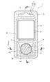
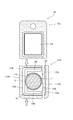
- FIG. 1 is a front view illustrating a schematic configuration of the battery package according to the first embodiment.
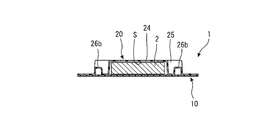
- 2 is a cross-sectional view taken along line II-II in FIG. 3 is a cross-sectional view taken along line III-III in FIG.
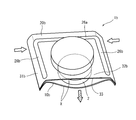
- FIG. 4 is a diagram illustrating a state in which the battery package is cut in a cuttable region.
- FIG. 5 is a diagram schematically showing how the battery is taken out from the cut battery package.
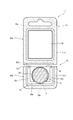
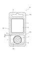
- FIG. 6 is a view corresponding to FIG. 1 illustrating a schematic configuration of the battery package according to the second embodiment.
- FIG. 7 is a diagram illustrating a state in which the battery package is cut in a cuttable region.
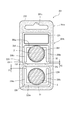
- FIG. 8 is a view corresponding to FIG. 1 illustrating a schematic configuration of the battery package according to the third embodiment.
- FIG. 9 is a view corresponding to FIG. 1 showing a schematic configuration of a battery package according to another embodiment.
- FIG. 1 is a diagram showing a schematic configuration of a battery package 1 according to Embodiment 1 of the present invention.
- 2 is a cross-sectional view taken along line II-II in FIG. 3 is a cross-sectional view taken along line III-III in FIG.
- the battery package 1 is a package for packaging coin-type batteries and button-type batteries, for example.
- the battery package 1 includes a mount 10 (first member) and a blister cover 20 (second member). That is, in the battery package 1 of the present embodiment, the mount 10 and the blister cover 20 are fixed.
- the battery package 1 includes a held portion 1 a that is held by a hook or the like of a store display shelf, and a battery storage portion 1 b that stores the battery 2.
- the held portion 1a and the battery storage portion 1b are arranged side by side in one direction. That is, the battery package 1 has a rectangular shape that is long in the one direction.
- the held portion 1a and the battery storage portion 1b are configured by combining parts of the mount 10 and the blister cover 20 respectively.
- the mount 10 is made of resin including, for example, PE (polyethylene) and PET (polyethylene terephthalate).
- the mount 10 is configured by laminating PET, PET on which Al is vapor-deposited, and PE sheets in the thickness direction. That is, the mount 10 is made of a material in which PET on which Al is deposited is disposed between PET and PE.
- the blister cover 20 is fixed to the surface on the PE side of the mount 10.
- the mount 10 is formed in a rectangular plate shape.
- the mount 10 may contain other resins (PS (polystyrene), PVC (polyvinyl chloride), etc.), or any material that functions as a mount. Also good. Further, the mount 10 may have unevenness.
- PS polystyrene
- PVC polyvinyl chloride
- the thickness of the mount 10 is smaller than the thickness of the blister cover 20. Further, the rigidity in the short direction of the mount 10 (the direction intersecting with the direction in which the non-fixed portion 32, the storage convex portion 24, and the first rib portion 26a described later are arranged) is more rigid than the short direction rigidity of the blister cover 20. Is also low.
- the mount 10 is formed with a through-hole 12 on one side in the longitudinal direction for hanging the battery package 1 on a hook of a display shelf of a store.
- One side in the longitudinal direction of the mount 10 constitutes a part of the held portion 1 a of the battery package 1.
- the blister cover 20 is made of resin including, for example, PE and PET.
- the blister cover 20 is formed in a rectangular shape in plan view so as to correspond to the mount 10.
- the mount 10 is fixed to the surface on the PE side.
- the blister cover 20 may be made of, for example, a laminate film made of PS, PVC, or other material as long as it is made of a transparent resin.
- the blister cover 20 is formed with a through hole 23 that forms a through hole 1 c of the battery package 1 together with the through hole 12 provided in the mount 10 on one side in the longitudinal direction. ing. That is, one side in the longitudinal direction of the blister cover 20 constitutes a held portion 1 a of the battery package 1 together with one side in the longitudinal direction of the mount 10.
- the blister cover 20 has a storage convex portion 24 that forms a storage space S for storing the battery 2 between itself and the mount 10 on the other side in the longitudinal direction when combined with the mount 10. That is, as shown in FIG. 2, the blister cover 20 has a shape in which a part of the longitudinal direction protrudes in the thickness direction in a side view.
- the storage convex part 24 has a dimension capable of storing the battery 2.
- the blister cover 20 is formed in a flat shape such that portions other than the storage convex portion 24, a convex portion 25 described later, and a rib portion 26 come into contact with the mount 10 in a state combined with the mount 10.
- the blister cover 20 has a rectangular protrusion 25 in plan view protruding in the thickness direction on the held part 1 a, and surrounds the storage protrusion 24 in the thickness direction.
- the rib portion 26 protrudes from the bottom.
- the rib portion 26 has a first rib portion 26 a provided on the other side in the longitudinal direction of the blister cover 20 and a pair of second ribs provided on both sides in the short direction of the blister cover 20 with respect to the storage convex portion 24. Part 26b.
- the first rib portion 26a is provided in the longitudinal direction of the blister cover 20 so as to protrude in the thickness direction of the blister cover 20 on the opposite side to the held portion 1a across the storage convex portion 24.
- the first rib portion 26 a is provided so as to extend linearly in the short direction of the blister cover 20. That is, the 1st rib part 26a is extended in the direction which cross
- the protruding height of the first rib portion 26 a is smaller than the protruding height of the storage convex portion 24.
- the length of the first rib portion 26a in the extending direction (the intersecting direction) is larger than the diameter of the battery 2 stored in the storage space S (the dimension in the intersecting direction). That is, the first rib portion 26 a protrudes outward from the battery 2 in the short direction of the blister cover 20 in a plan view of the battery package 1.
- the rigidity of the first rib portion 26a is higher than the rigidity of the fixed portion between the mount 10 and the blister cover 20 that is located in the extending direction (the intersecting direction) with respect to the first rib portion 26a.
- the first rib portion 26 a has a central portion in the extending direction connected to the storage convex portion 24. That is, the first rib portion 26a and the storage convex portion 24 are partly integrated. Thereby, the battery packaging body 1 can be made compact in the longitudinal direction of the battery packaging body 1.
- the 1st rib part 26a and the storage convex part 24 may be provided separately.
- the pair of second rib portions 26b are provided on both sides of the storage convex portion 24 in the short direction of the blister cover 20 so as to protrude in the thickness direction of the blister cover 20.
- Each second rib portion 26b is provided to extend linearly in the longitudinal direction of the blister cover 20 (the direction in which the non-fixed portion 32, the storage convex portion 24, and the first rib portion 26a are arranged).
- a pair of 2nd rib part 26b is extended in the direction orthogonal to the 1st rib part 26a.
- the pair of second rib portions 26b are orthogonal to the first rib portion 26a.
- the present invention is not limited to this, and it is only necessary to intersect the first rib portion 26a.
- the protruding height of the second rib portion 26 b is smaller than the protruding height of the storage convex portion 24.
- Each of the second rib portions 26b has a length in the extending direction larger than the diameter of the battery 2 stored in the storage space S (the dimension in the extending direction). Note that the length in the extending direction of each second rib portion 26 b may be smaller than the diameter of the battery 2.
- the first rib portion 26a and the pair of second rib portions 26b are integrally formed. That is, one pair of the pair of second rib portions 26b is connected to both ends of the first rib portion 26a in the short direction of the blister cover 20 in the longitudinal direction of the blister cover 20. Thereby, the rib part 26 is formed in the substantially U shape by planar view so that the storage convex part 24 may be enclosed. Note that the substantially U-shape includes not only a U-shaped curve but also a shape having corners.
- first rib portion 26a and the pair of second rib portions 26b each have a substantially semicircular cross section perpendicular to the extending direction.
- the first rib portion 26a and the pair of second rib portions 26b may each have a cross section other than a substantially semicircular shape.
- the rigidity of the battery package 1 can be ensured.
- the battery package 1 can increase the rigidity around the storage convex portion 24, so that the storage space S in which the battery 2 is stored can be prevented from being crushed.
- the rib portion 26 as will be described later, when the battery 2 is taken out from the storage space S by cutting the non-fixed portion 32 between the mount 10 and the blister cover 20, the mount 10 and the blister cover 20 are removed. It can be easily deformed. Therefore, the battery 2 can be easily taken out from the storage space S of the battery package 1.
- the mount 10 and the blister cover 20 are portions other than the storage convex portions 24, the convex portions 25, and the rib portions 26, and adhesives (for example, a mixed resin of polyester resin and epoxy resin, acrylic resin, polyvinyl acetate copolymer resin, etc.) ) Or heat welding or the like. That is, the mount 10 and the blister cover 20 are fixed at least at the outer peripheral edge. The mount 10 and the blister cover 20 are also fixed between the convex portion 25, the storage convex portion 24, and the rib portion 26 in the longitudinal direction of the battery package 1. In FIG. 1, the range of the fixing portion 31 to which the mount 10 and the blister cover 20 are fixed is indicated by a dotted area.
- the infant can be prevented from opening the battery pack 1 easily.
- the battery packaging body 1 has a mount 10 and a blister cover 20 on one side of the storage convex portion 24 and the rib portion 26, that is, on the side opposite to the first rib portion 26 a across the storage convex portion 24.
- the non-fixed portion 32 is located between the convex portion 25 and the storage convex portion 24 and the rib portion 26 and is connected to the storage convex portion 24 and the rib portion 26. That is, there is no fixed portion between the non-fixed portion 32 and the storage convex portion 24 and the rib portion 26.
- the non-fixed part 32 is arranged in the short direction of the battery package 1 (the non-fixed part 32 and the storage convex part 24) on the opposite side of the first rib part 26 a across the storage convex part 24 in the longitudinal direction of the battery package 1. And a direction that intersects the direction in which the first rib portions 26a are arranged) so as to extend linearly.
- the non-fixed portion 32 constitutes a part of the severable region P that is cut by scissors or the like when opening the battery package 1. That is, since the opening 33 is formed in the non-fixed portion 32 by cutting the battery package 1 in the short direction so as to include the non-fixed portion 32, the battery 2 in the storage space S can be removed from the opening 33. It can be taken out.
- the battery package 1 has a non-fixed part also around the convex part 25 and the rib part 26 (refer the white background part in FIG. 1).
- the battery package 1 may not have non-fixed parts other than the above-described non-fixed part 32.
- the cuttable area P is constituted by a part of the non-fixed part 32.
- the severable region P extends linearly in the short direction of the battery package 1 (the direction intersecting the direction in which the non-fixed portion 32, the storage convex portion 24, and the first rib portion 26a are arranged). ing.
- the cuttable region is not limited to a linear shape, and may be an arc shape or the like.
- the severable region P at least the central portion of the blister cover 20 in the short direction when viewed from the thickness direction is a flat plate shape parallel to the mount 10 in the thickness direction. That is, in the cuttable region P, at least the central portion in the short direction is not formed with unevenness on the blister cover 20.
- the blister cover 20 in the severable region P, has a flat plate shape parallel to the mount 10 in the thickness direction.
- the non-fixed portion 32 the severable region P is located in the direction in which the non-fixed portion, the storage convex portion, and the first rib portion are aligned with respect to the second rib portion 26b.
- the severable region P does not overlap the second rib portion 26 b of the blister cover 20 in the non-fixed portion 32 when viewed from the thickness direction of the blister cover 20. Thereby, the battery package 1 can be easily cut
- the parallel means that the blister cover 20 is disposed along the mount 10 and the distance between the mount 10 and the blister cover 20 is equal.
- the battery package 1 As shown in FIG. 4, when the severable region P of the battery package 1 is cut with scissors or the like, the battery package 1 is separated into the held portion 1a and the battery storage portion 1b. Thereby, when the battery package 1 is opened, the unnecessary held portion 1a can be removed.
- the battery package 1 is cut so as to pass through the non-fixed portion 32 by cutting the severable region P of the battery package 1 with scissors or the like.
- the blister covers after being cut in the cuttable area P are blister covers 20a and 20b, respectively, and the mounts after being cut in the cuttable area P are called mounts 10a and 10b, respectively.
- the non-fixed portions after cutting are set as non-fixed portions 32a and 32b, respectively, and the fixed portions after cutting are set as fixed portions 31a and 31b, respectively.
- the non-fixed portion 32 is divided into the non-fixed portions 32a and 32b by cutting the severable region P of the battery package 1 with scissors or the like.
- the opening 33 is formed in the cut end surface X of the non-fixed portion 32b.
- the non-fixed part 32 b is connected to the storage convex part 24. Therefore, by forming the opening 33 in the non-fixed portion 32 b, the storage space S formed by the storage convex portion 24 is connected to the outside through the opening 33.
- the non-fixed portion 32b is formed in a planar shape along the mount 10b, the opening area of the opening 33 is small. Therefore, in order to take out the battery 2 to the outside, it is necessary to expand the opening area of the opening 33 to a size that allows the battery 2 to pass through.
- a force is applied to the battery housing portion 1b so that both end portions of the battery housing portion 1b located on the extension line in the extending direction of the first rib portion 26a are brought closer (FIG. 5).
- the opening 33 can be greatly expanded by the white arrow in the figure.
- the both end portions are outer portions in the extending direction of the first rib portion 26a in the battery housing portion 1b.
- the battery storage in the crossing direction is performed. Both ends of the portion 1b are bent in the same direction of the thickness direction. Thereby, in the cuttable region P, a gap is generated between the mount 10 and the non-fixed portion 32b of the blister cover 20 over the entire intersecting direction. Thereby, the opening 33 can be expanded to a size through which the battery 2 can pass.
- the battery housing portion 1b is formed on the second rib portion 26b. Bend along.
- the mount 10 compresses the mount 10 and the blister cover 20 cut in the cuttable region P in a direction intersecting the direction in which the non-fixed portion 32b, the storage convex portion 24, and the first rib portion 26a are arranged.
- the cut end surface X formed by cutting the cuttable region P When viewed from the direction in which the non-fixed portion 32b, the storage convex portion 24, and the first rib portion 26a are arranged, the region corresponding to the storage convex portion 24 in the intersecting direction is bent in the thickness direction with respect to the blister cover 20. It is comprised so that it may space apart.
- the mount 10 has a thickness smaller than the thickness of the blister cover 20 so that the above-described deformation can be realized.
- the thickness of the mount 10 is preferably 3/4 or less, more preferably 1/2 or less, still more preferably 1/3 or less, and most preferably 1/4 or less with respect to the thickness of the blister cover 20.
- the 2nd rib part 26b contributes to improving the rigidity of parts other than the 1st rib part 26a in the battery accommodating part 1b. Therefore, by providing the second rib portion 26b, the opening 33 can be further enlarged.
- the battery 2 can be easily taken out from the opening 33 by expanding the opening 33 in this way.
- the rigidity of the first rib portion 26a is higher than the rigidity of the portion of the fixed portion between the mount 10 and the blister cover 20 that is located in the extending direction (the intersecting direction) with respect to the first rib portion 26a.
- the both ends are mounted in the thickness direction in the thickness direction so that both ends in the direction intersecting with the direction in which the non-fixed portion 32b, the storage convex portion 24, and the first rib portion 26a are aligned.
- the mount 10 can be easily deformed with respect to the blister cover 20 at the cut end surface X by being bent and pressed to the side. Therefore, the both ends of the battery storage unit 1b are bent and pressed in the thickness direction toward the mount 10 so as to bring the both ends in the intersecting direction closer to each other.
- the opening of the cut end face X can be more easily expanded by being separated easily.
- the opening 33 appears in the non-fixed portion 32b by cutting the severable region P of the battery package 1 with scissors or the like. Accordingly, the battery 2 cannot be taken out from the battery package 1 when the severable area P is not cut, but the battery 2 can be taken out from the battery pack 1 by cutting the severable area P. It becomes possible.
- a battery package 1 is obtained in which an infant cannot easily take out the battery 2 while a person other than the infant uses the battery 2 can easily take out the battery 2.
- the battery packaging body 1 of the present embodiment can take out the battery 2 by cutting it with scissors or the like without peeling off the blister cover 20 and the mount 10. Therefore, even after the battery 2 is taken out from the battery package 1, the configuration of the battery storage portion 1b is maintained, so that the replaced battery or the like can be stored again in the storage space S. Accordingly, when the used battery is stored until it is discarded or carried into the recovery BOX, the used battery is stored in the battery storage section 1b without using a fixing member or the like by bending the opening. The state accommodated in the space S, that is, the state where the used battery is covered with the mount 10 and the blister cover 20 can be maintained. Therefore, it is possible to prevent the battery from being short-circuited.
- FIG. 6 schematic structure of the battery package 101 which concerns on Embodiment 2 of this invention is shown.
- the configuration of the rib portion 126 provided on the blister cover 120 is different from the configuration of the first embodiment.
- the same components as those in the first embodiment are denoted by the same reference numerals as those in the first embodiment, and the description thereof will be omitted. Only the components different from those in the first embodiment will be described.
- the battery package 101 includes a mount 110 and a blister cover 120, similar to the battery package 1 of the first embodiment.
- the mount 110 and the blister cover 120 are fixed by an adhesive or the like other than the storage convex portion 124, the convex portion 125, and the rib portion 126 described later.
- the mount 110 and the blister cover 120 are made of the same material as the mount 10 and the blister cover 20 of the first embodiment, respectively.
- the battery package 101 includes a held portion 101a and a battery storage portion 101b.
- the held portion 101 a is located on one side in the longitudinal direction of the battery package 101.
- the battery housing part 101 b is located on the other side in the longitudinal direction of the battery package 101. That is, the held portion 101a and the battery storage portion 101b are arranged side by side in one direction. Therefore, the battery package 101 has a rectangular shape that is long in the one direction.
- the battery package 101 according to the present embodiment has a shorter length in the short direction than the battery package 1 of the first embodiment.
- the configuration of the held portion 101a has the same configuration as the held portion 1a of the first embodiment, detailed description thereof is omitted.
- symbol 101c is a through-hole
- symbol 125 is a convex part.
- the battery storage part 101b has a storage convex part 124 and a rib part 126 formed on the blister cover 120.
- the storage convex portion 124 forms a storage space S having a size capable of storing the battery 2 between the mount 110.
- the rib portion 126 includes a first rib portion 126 a that extends linearly in the longitudinal direction of the blister cover 120 and a pair of second rib portions 126 b that extend linearly in the short direction of the blister cover 120.
- the first rib portion 126 a is located on one side with respect to the storage convex portion 124 in the short direction of the blister cover 120.
- the first rib portion 126 a has a length larger than the diameter (dimension) of the battery 2 in the longitudinal direction of the blister cover 120.
- stretching direction is connected with the accommodating convex part 124.
- the rigidity of the first rib portion 126a is higher than the rigidity of the fixed portion between the mount 10 and the blister cover 120 that is located in the extending direction (the intersecting direction) with respect to the first rib portion 126a.
- the pair of second rib portions 126b are located on both sides of the storage convex portion 124 in the longitudinal direction of the blister cover 120.
- Each second rib portion 126 b has a length larger than the diameter (dimension) of the battery 2 in the short direction of the blister cover 120.
- the first rib portion 126a and the pair of second rib portions 126b are integrally formed. That is, the pair of second rib portions 126b are connected to both ends of the first rib portion 126a in the longitudinal direction of the blister cover 120 in the short direction of the blister cover 120. Thereby, the rib part 126 is formed in the substantially U shape so that the storage convex part 124 may be enclosed.
- the 1st rib part 126a and the 2nd rib part 126b have the same structure except the arrangement
- FIG. 1st rib part 126a and the 2nd rib part 126b have the same structure except the arrangement
- the rigidity around the storage convex portion 124 can be improved by providing the rib portion 126 as described above.
- the first rib portion 126a as described above, when the battery 2 is taken out from the battery package 101, it is formed on the cut end surface by cutting a cuttable region P described later, as will be described later.
- the opening 133 can be greatly expanded. Therefore, the battery 2 can be easily taken out from the storage space S.
- the mount 110 and the blister cover 120 are adhesives (for example, a mixed resin of a polyester resin and an epoxy resin, an acrylic resin, a vinyl chloride vinyl chloride copolymer resin, etc.) other than the storage convex portion 124, the convex portion 125, and the rib portion 126. Or it is fixed by heat welding or the like. That is, the mount 110 and the blister cover 120 are fixed at least at the outer peripheral edge. Further, the mount 110 and the blister cover 120 are also fixed between the convex portion 125, the storage convex portion 124 and the rib portion 126. In FIG. 6, the range of the fixing part 131 to which the mount 110 and the blister cover 120 are fixed is indicated by a dotted area.
- the infant can be prevented from opening the battery package 101 easily.
- the battery package 101 has a non-fixed portion 132 to which the mount 110 and the blister cover 120 are not fixed on the other side in the short side direction, that is, on the side opposite to the first rib portion 126a across the storage convex portion 124.
- the non-fixed part 132 is connected to the storage convex part 124 and the rib part 126. That is, there is no fixed portion between the non-fixed portion 132 and the storage convex portion 124 and the rib portion 126.
- the non-fixed portion 132 is provided on the opposite side to the first rib portion 126a across the storage convex portion 124 in the short direction of the battery package 101 so as to extend linearly in the longitudinal direction of the battery package 101. Yes. As will be described later, the non-fixed portion 132 constitutes a part of the cuttable region P that is cut by scissors or the like when the battery package 101 is opened. That is, the battery packaging body 101 is cut in the longitudinal direction so as to include the non-fixed portion 132, so that the opening 133 is formed in the non-fixed portion 132, and thus the battery 2 in the storage space S is taken out from the opening 133. be able to.
- the battery package 101 has a non-fixed part also around the convex part 125 and the rib part 126 (refer the white background part in FIG. 6).
- the battery package 101 may not have any non-fixed part other than the above-described non-fixed part 132.
- the cuttable region P at least the central portion of the blister cover 120 in the longitudinal direction when viewed from the thickness direction is a flat plate shape parallel to the mount 110 in the thickness direction. That is, in the cuttable region P, the blister cover 120 is not uneven at least in the central portion in the longitudinal direction. In the present embodiment, in the cuttable region P, the blister cover 120 has a flat plate shape parallel to the mount 110 in the thickness direction. Further, in the non-fixed portion 132, the severable region P is located in the direction in which the non-fixed portion, the storage convex portion, and the first rib portion are aligned with respect to the second rib portion 126b. That is, the cuttable region P does not overlap the second rib portion 126b of the blister cover 120 in the non-fixed portion 132 when viewed from the thickness direction of the blister cover 120. Thereby, the battery package 101 can be easily cut in the cuttable region P.
- the parallel means that the blister cover 120 is disposed along the mount 110 and the distance between the mount 110 and the blister cover 120 is equal.
- the battery packaging body 101 is separated into the held portion 101a and the battery housing portion 101b. Thereby, the unnecessary held portion 101a can be removed when the battery package 101 is opened.
- the severable area P of the battery housing 101b is cut with scissors or the like.
- the blister covers after being cut in the cuttable area P are blister covers 120a and 120b, respectively, and the mounts after being cut in the cuttable area P are called mounts 110a and 110b.
- the non-fixed portions after being cut in the possible region P are referred to as non-fixed portions 132a and 132b, respectively.
- the non-fixed portion 132 is divided into the non-fixed portions 132a and 132b by cutting the severable region P of the battery housing portion 101b with scissors or the like.
- the opening 133 is formed in the cut end face of the non-fixed portion 132b.
- the non-fixed part 132 b is connected to the storage convex part 124. Therefore, by forming the opening 133 in the non-fixed portion 132b, the storage space S formed by the storage convex portion 124 is connected to the outside through the opening 133.
- the non-fixed portion 132b is formed in a planar shape along the mount 110b, the opening area of the opening 133 is small. Therefore, in order to take out the battery 2 to the outside, it is necessary to expand the opening area of the opening 133 to a size that allows the battery to pass through.
- the opening 133 is formed by applying a force so that the both ends of the battery housing portion 101b positioned on the extension line in the extending direction of the first rib portion 126a are brought closer to the battery housing portion 101b after cutting. Can be greatly expanded.
- the both end portions are outer portions in the extending direction of the first rib portion 26a in the battery housing portion 1b.
- the battery housing in the intersecting direction is performed. Both ends of the portion 101b are bent in the same direction of the thickness direction. As a result, in the severable region P, a gap is generated between the mount 110 and the non-fixed portion 132b of the blister cover 120 over the entire intersecting direction. Thereby, the opening 133 can be expanded to a size through which the battery 2 can pass. As described above, when the both ends of the battery housing portion 101b in the intersecting direction are bent in the same thickness direction (the side of the mount 110), the battery housing portion 101b is connected to the second rib portion 126b. Bend along.
- the first rib portion 126a is stretched in the extending direction (the intersecting direction), but more rigid in the intersecting direction than the blister cover 120.
- the low mounting sheet 110 is bent so as to be separated from the blister cover 120 in the thickness direction by approaching both ends in the intersecting direction, and the opening 133 between the blister cover 120 and the blister cover 120 is greatly expanded.
- the mount 110 compresses the mount 110 and the blister cover 120 cut in the cuttable region P in a direction intersecting the direction in which the non-fixed portion 132b, the storage convex portion 124, and the first rib portion 126a are arranged.
- the cut end surface formed by cutting the cuttable region P when both ends of the mount 110 and the blister cover 120 in the intersecting direction are bent in the same thickness direction (the mount 110 side)
- the region corresponding to the storage convex portion 124 in the intersecting direction is bent in the thickness direction and separated from the blister cover 120. Is configured to do.
- the 2nd rib part 126b contributes to improving the rigidity of parts other than the 1st rib part 126a in the battery storage part 101b after a cutting
- the battery 2 can be easily taken out from the opening 133 by expanding the opening 133 in this manner.
- the rigidity of the first rib portion 126a is higher than the rigidity of the portion of the fixing portion between the mount 110 and the blister cover 120 that is located in the extending direction (the intersecting direction) with respect to the first rib portion 126a.
- the both ends are mounted in the thickness direction in the thickness direction so that both end portions in the direction intersecting the direction in which the non-fixed portion 132b, the storage convex portion 124, and the first rib portion 126a intersect.
- the mount 110 can be easily deformed with respect to the blister cover 120 at the cut end face. Therefore, the both ends of the battery storage portion 101b are bent and pressed in the thickness direction toward the mount 110 so as to bring the both ends in the intersecting direction closer to each other.
- the opening of the cut end face can be more easily widened by being easily separated.
- the battery 2 can be easily taken out by an infant, but when a person other than the infant uses the battery 2, the battery package 101 can be easily taken out. .
- the battery package 101 of the present embodiment can be taken out of the battery 2 by cutting it with scissors or the like without peeling off the blister cover 120 and the mount 110. Therefore, even after the battery 2 is taken out from the battery package 1, the configuration of the battery storage portion 101 b is maintained, so that the replaced battery or the like can be stored again in the storage space S.
- the used battery when storing the used battery until it is discarded or carrying it until it is put in the recovery BOX, the used battery is stored in the battery storage unit 101b without using a fixing member or the like by bending the opening.
- a state where the battery is stored in the storage space S that is, a state where the used battery is covered with the mount 110 and the blister cover 120 can be maintained. Therefore, it is possible to prevent the battery from being short-circuited.
- FIG. 8 schematic structure of the battery package 201 which concerns on Embodiment 3 of this invention is shown.
- the battery package 201 of this embodiment is different from the configuration of Embodiment 1 in that the battery storage portion 201b is provided with two storage convex portions 224 and 254 and two rib portions 226 and 256.
- the same components as those in the first embodiment are denoted by the same reference numerals as those in the first embodiment, and the description thereof will be omitted. Only the components different from those in the first embodiment will be described.
- the battery package 201 has a mount 210 and a blister cover 220 as in the battery package 1 of the first embodiment.
- the mount 210 and the blister cover 220 are fixed by an adhesive or the like other than the storage convex portions 224 and 254, the convex portion 225, and the rib portions 226 and 256 described later.
- the mount 210 and the blister cover 220 are made of the same material as the mount 10 and the blister cover 20 of the first embodiment, respectively.
- the battery package 201 has a held portion 201a and a battery storage portion 201b.
- the held portion 201 a is located on one side in the longitudinal direction of the battery package 201.
- the battery housing part 201 b is located on the other side in the longitudinal direction of the battery package 201. That is, the held portion 201a and the battery storage portion 201b are arranged side by side in one direction. Therefore, the battery package 201 has a rectangular shape that is long in the one direction.
- the configuration of the held portion 201a has the same configuration as the held portion 1a of the first embodiment, detailed description thereof is omitted.
- symbol 201c is a through hole
- symbol 225 is a convex part.
- the battery storage portion 201b has storage convex portions 224 and 254 and rib portions 226 and 256 formed on the blister cover 220.
- the storage convex portions 224 and 254 form storage spaces S ⁇ b> 1 and S ⁇ b> 2 having a size capable of storing the battery 2, respectively, with the mount 210.
- the storage convex portions 224 and 254 are provided side by side in the longitudinal direction of the blister cover 220.
- the rib portion 226 is formed in a substantially U shape so as to surround the storage convex portion 224.
- the rib portion 256 is formed in a substantially U shape so as to surround the storage convex portion 254.
- Each of the rib portions 226 and 256 includes first rib portions 226 a and 256 a that extend in the short direction of the blister cover 220, and a pair of second rib portions 226 b and 256 b that extend in the longitudinal direction of the blister cover 220.
- the rib portions 226 and 256 are provided such that the first rib portions 226a and 256a are located on the opposite side of the storage convex portions 224 and 254 in the longitudinal direction of the blister cover 220.
- the non-fixed portions 232 and 262 are provided between the storage convex portions 224 and 254 in the longitudinal direction of the blister cover 220.
- a fixing portion 231 is provided between the non-fixing portions 232 and 262. Since the configuration of the non-fixed portions 232 and 262 is the same as the configuration of the non-fixed portion 32 in the first embodiment, detailed description thereof is omitted.
- the rib portions 226, 256, the storage convex portions 224, 254, and the non-fixed portions 232, 262 sandwich the fixing portion 231 located between the non-fixed portions 232, 262, and the battery package 201 Are arranged symmetrically in the longitudinal direction.
- the positional relationship between the rib portion 226, the storage convex portion 224, and the non-fixed portion 232 is the same as that of the present embodiment, and the positional relationship between the rib portion 256, the storage convex portion 254, and the non-fixed portion 262 is the present embodiment.
- the arrangement and orientation of the rib portions 226, 256, the storage convex portions 224, 254, and the non-fixed portions 232, 262 are not limited to the configuration of this embodiment.
- the cuttable areas P1 and P2 constituted by a part of the non-fixed portions 232 and 262 are cut with scissors or the like, respectively. That is, when the battery 2 in the storage space S ⁇ b> 1 is taken out, the cuttable area P ⁇ b> 1 constituted by a part of the non-fixed portion 232 is cut. On the other hand, when the battery 2 in the storage space S ⁇ b> 2 is taken out, the severable region P ⁇ b> 2 configured by a part of the non-fixed portion 262 is cut.
- the method for taking out the battery 2 after cutting is the same as in the first embodiment.
- the battery 2 can be easily taken out by an infant, while the battery package 201 can be easily taken out when a person other than the infant uses the battery 2. .
- the rib portions 26, 126, 226, and 256 have the second rib portions 26b, 126b, 226b, and 256b.
- the rib portion may not have the second rib portion. That is, the rib part may have only the 1st rib part.
- the blister cover 320 has a first rib portion 26 a extending in the short direction of the battery package 301, while having a second rib portion as in each of the above embodiments.
- the battery packaging body 301 has the non-fixed portion 32 on the opposite side to the first rib portion 26a across the storage convex portion 24 in the longitudinal direction.
- the battery 2 in the storage space S can be taken out by cutting the severable region P constituted by a part of the non-fixed portion 32 with scissors or the like.
- reference numeral 301a is a held part
- reference numeral 301b is a battery storage part.
- the blister cover may have ribs other than the first rib portion and the second rib portion.
- the first rib portions 26a, 126a, 226a, 256a and the second rib portions 26b, 126b, 226b, 256b are orthogonal to each other.
- the 1st rib part and the 2nd rib part are extended in the direction which cross
- first rib portions 26a, 126a, 226a, 256a and the second rib portions 26b, 126b, 226b, 256b of the rib portions 26, 126, 226, 256 are each linear. However, one or both of the first rib portion and the second rib portion may be curved.
- the battery package 1, 101, 201, 301 is rectangular in plan view.
- the battery package may have a shape other than the rectangular shape.
- the rib portions 26, 126, 226, and 256 have a protruding height smaller than that of the storage convex portions 24, 124, 224, and 254.
- the rib portion may have a protruding height larger than that of the storage convex portion.
- the blister covers 20, 120, 220, 320 have the storage convex portions 24, 124, 224, 254, the rib portions 26, 126, 226, 256, the convex portions 25, 125, 225, and the non-fixed portion 32. , 132, 232, 262 are provided.
- the mount may be provided with storage convex portions, rib portions, convex portions, and non-fixed portions, or both the blister cover and mount may be provided with storage convex portions, rib portions, convex portions, and non-fixed portions. Good.
- the mount 10, 110, 210 and the blister cover 20, 120, 220, 320 are bonded and fixed.
- the fixing method of the mount and the blister cover may be a welding fixing or a fixing method using a fixing member or the like other than the adhesive fixing described in the above embodiments.
- the mount 10, 110, 210 and the blister cover 20, 120, 220, 320 include the through holes 1c, 101c, 201c, the storage convex portions 24, 124, 224, 254, the rib portions 26, 126, The planes of the portions excluding 226, 256 and the convex portions 25, 125, 225 are bonded and fixed.
- the portions other than the through holes, the storage convex portions, the rib portions, and the convex portions may not be flat, and all of the removed portions may not be bonded and fixed.
- the mount and the blister cover need to be bonded and fixed at their outer peripheral edge portions.
- the mount 10 has a thickness smaller than the thickness of the blister cover 20.
- the mount may have a thickness that is equal to or greater than the thickness of the blister cover.
- the battery 2 packaged by the battery packs 1, 101, 201, 301 is a button type battery or a coin type battery.
- the configuration of the above embodiment may be applied to the battery package.
- the battery package according to the present invention can be used for packaging small batteries such as button-type batteries and coin-type batteries.
Landscapes
- Engineering & Computer Science (AREA)
- Mechanical Engineering (AREA)
- Chemical & Material Sciences (AREA)
- Composite Materials (AREA)
- Packages (AREA)
- Battery Mounting, Suspending (AREA)
Abstract
乳幼児が電池を取り出しにくくしつつ、乳幼児以外の人は電池を取り出し可能な電池包装体の構成を得る。電池包装体1は、台紙10と、台紙10との間に電池2を収納可能なブリスターカバー20とを備える。台紙10とブリスターカバー20とは、少なくともそれらの外周縁部で固定されている。ブリスターカバー20は、収納凸部24と繋がる位置で台紙10に対して固定されていない非固定部32と、収納凸部24に沿うように設けられた第1リブ部26aとを有する。非固定部32は、第1リブ部26aに対して収納凸部24を挟んで反対側に位置し且つ切断可能領域Pの一部を構成する。第1リブ部26aは、非固定部32、収納凸部24及び第1リブ部26aが並ぶ方向に対して交差する方向に延びている。
Description
本発明は、電池を包装するための電池包装体に関する。
電池を包装するための電池包装体が知られている。このような電池包装体として、例えば特許文献1には、台紙と、収納部を有し且つ前記台紙に固定されるブリスターカバーとからなるブリスターパッケージが開示されている。このようなブリスターパッケージでは、台紙とブリスターカバーとの間に前記収納部によって形成される収納空間内に、電池が収納される。
上述のような構成を有するブリスターパッケージには、一般的に、台紙の収納部に対応する位置にミシン目などが設けられている。そのため、前記収納空間内に収納された電池をブリスターパッケージから取り出す場合には、台紙のミシン目を破って電池を取り出したり、ブリスターカバー上から電池を台紙側に押し込むことにより、電池が台紙を突き破るようにして該電池を取り出したりする方法が採用されている。一方、上述のようなミシン目が台紙に設けられていない場合には、台紙とブリスターカバーとを剥離して、電池を取り出す。
上述のような構成を有する電池包装体では、電池を容易に取り出せるような構成を採用している。そのため、乳幼児が電池包装体から電池を容易に取り出して、電池を誤飲する可能性がある。
これに対し、例えば特許文献2に開示されているようなブリスター容器を、電池包装体として用いることにより、乳幼児が容易に電池を開封できないようにすることが考えられる。この特許文献2に開示されているブリスター容器では、ブリスターカバーに、一部が浅く形成された切断予定部が設けられている。ハサミ等を用いて切断予定部を台紙ごと切断することによって現れた開口部を利用してブリスターカバーと台紙とを剥がすことにより、乳幼児には開封困難だが、乳幼児以外の者は内部の固形物品を取り出すことができる。
ところで、上述の特許文献2に開示されている構成では、ブリスターカバーに、一部が浅く形成されることによって切断予定部が設けられている。そのため、ブリスター容器において、ブリスターカバーが立体的に形成された部分(立体部分)の占める割合が大きい。
また、上述の特許文献2に開示されているブリスター容器は、そもそも、ブリスターカバーと台紙とを剥がすことにより電池を取り出す構造を有する。そのため、ブリスターカバーと台紙との接着力はあまり大きくない。
そのため、乳幼児がブリスター容器を曲げたり捻じったりした場合に、ブリスターカバーの立体部分が大きな力を受けて破損したり、ブリスターカバーと台紙とが剥がれたりして、乳幼児が電池を取り出す可能性がある。
よって、上述の特許文献2に開示されているブリスター容器を電池包装体に適用した場合でも、乳幼児が電池包装体を破壊して、内部の電池を取り出し、誤飲する可能性がある。一方で、当然のことながら、電池包装体は、乳幼児以外の人が電池を使用する際に、電池包装体から電池を取り出せるような構成を有する必要がある。
本発明の目的は、電池を包装するための電池包装体において、乳幼児が電池を取り出しにくくしつつ、乳幼児以外の人は電池を取り出し可能な電池包装体の構成を得ることにある。
本発明の一実施形態に係る電池包装体は、電池を包装するための電池包装体である。この電池包装体は、第1部材と、前記第1部材との間に前記電池を収納可能な第2部材とを備える。前記第1部材と前記第2部材とは、少なくともそれらの外周縁部で固定されている。前記第2部材は、前記第1部材との間に前記電池を収納可能な収納空間を形成するように前記第2部材の厚み方向に突出した収納凸部と、前記収納凸部と繋がる位置に設けられるとともに、前記第1部材に対して固定されていない非固定部と、前記収納凸部に沿うように設けられるとともに、前記第2部材の厚み方向に突出した第1リブ部と、を有する。前記非固定部は、前記第1リブ部に対して前記収納凸部を挟んで反対側に位置するとともに、電池包装体を開封する際に切断される切断可能領域の一部を構成する。前記第1リブ部は、前記非固定部、前記収納凸部及び前記第1リブ部が並ぶ方向に対して交差する方向に延びている(第1の構成)。
上述の構成を有する電池包装体は、第1部材及び第2部材が少なくとも外周縁部で固定されているため、切断可能領域で切断する前は、電池包装体を開封するための開封部分が存在しない。そのため、乳幼児は前記電池包装体から電池を容易に取り出すことができない。
前記電池包装体を、収納凸部と繋がった非固定部を含む切断可能領域で切断することにより、その切断端面における前記第1部材と前記第2部材との間に開口を設けることができる。前記非固定部は、第1リブ部に対して前記収納凸部を挟んで反対側に位置するため、前記切断可能領域で切断した際に前記開口が設けられる部分は、前記収納凸部を挟んで前記第1リブ部とは反対側の位置である。
上述の構成では、前記第1リブ部は、前記非固定部、前記収納凸部及び前記第1リブ部が並ぶ方向に対して交差する方向に延びている。よって、切断後の電池包装体において、前記第1リブ部の延伸方向の延長線上に位置する前記電池包装体の両端部を近づけるように、該両端部を厚み方向に第1部材側に折り曲げて押圧した場合、前記第1リブ部が前記交差する方向に圧縮される力を受ける一方、前記切断端面で前記第1部材と前記第2部材とが大きく離間して、開口が大きく拡がる。これにより、前記収納凸部によって形成された収納空間内から電池を容易に取り出すことができる。
前記第1の構成において、前記切断可能領域は、前記交差する方向に直線状に延びている(第2の構成)。これにより、電池包装体から電池を取り出す際に、前記電池包装体を切断可能領域で容易に切断できる。
前記第1または第2の構成において、前記第1リブ部は、前記交差する方向において、前記電池の寸法よりも大きい長さを有する(第3の構成)。これにより、切断可能領域で切断された電池包装体において、非固定部、収納凸部及び第1リブ部が並ぶ方向に対して交差する方向の両端部を近づけるように、該両端部を厚み方向に第1部材側に折り曲げて押圧することにより、切断端面において第1部材と第2部材とをより大きく離間させて、前記切断端面の開口をより大きく拡げることができる。よって、前記収納凸部によって形成された収納空間内から電池をより容易に取り出すことができる。
前記第1から第3の構成のうちいずれか一つの構成において、前記第2部材は、前記収納凸部に沿うように、前記非固定部、前記収納凸部及び前記第1リブ部が並ぶ方向に延びる第2リブ部を有する(第4の構成)。
これにより、電池包装体において、非固定部、収納凸部及び第1リブ部が並ぶ方向の剛性を向上できる。しかも、切断可能領域で切断された電池包装体において、非固定部、収納凸部及び第1リブ部が並ぶ方向に対して交差する方向の両端部を近づけるように、該両端部を厚み方向に第1部材側に折り曲げて押圧することにより、切断端面において第1部材と第2部材とをより容易に離間させて、前記切断端面の開口をより容易に拡げることができる。
前記第4の構成において、前記第2リブ部は、前記第1リブ部に接続されている(第5の構成)。これにより、電池包装体の剛性をより向上できる。しかも、切断可能領域で切断された電池包装体において、非固定部、収納凸部及び第1リブ部が並ぶ方向に対して交差する方向の両端部を近づけるように、該両端部を厚み方向に第1部材側に折り曲げて押圧することにより、切断端面において第1部材と第2部材とをより容易に離間させて、前記切断端面の開口をより容易に拡げることができる。
前記第5の構成において、前記第1リブ部及び第2リブ部は、前記第2部材の厚み方向から見て全体としてU字状に形成されている(第6の構成)。これにより、電池包装体の剛性をより向上できる。しかも、切断可能領域で切断された電池包装体において、非固定部、収納凸部及び第1リブ部が並ぶ方向に対して交差する方向の両端部を近づけるように、該両端部を厚み方向に第1部材側に折り曲げて押圧することにより、切断端面において第1部材と第2部材とをより容易に離間させて、前記切断端面の開口をより容易に拡げることができる。
前記第4から第6の構成のうちいずれか一つの構成において、前記切断可能領域において、前記第2部材のうち、前記第2部材の厚み方向から見て前記交差する方向の少なくとも中央部分は、前記第1部材に対して厚み方向に平行な平板状である(第7の構成)。
これにより、切断可能領域において、第2部材のうち、前記交差する方向の少なくとも中央部分に凹凸がないため、前記第2部材を前記切断可能領域で容易に切断することができる。なお、平行とは、前記第2部材が第1部材に沿って配置され、前記第1部材と前記第2部材との間隔が、前記切断可能領域において同等である状態を意味する。
前記第4から第7の構成のうちいずれか一つに記載の構成において、前記切断可能領域において、前記第2部材は、前記第1部材に対して厚み方向に平行な平板状である。前記切断可能領域は、前記非固定部において、第2部材の厚み方向から見て前記第2リブ部と重なっていない(第8の構成)。
これにより、切断可能領域に凹凸がないため、第2部材を前記切断可能領域でより容易に切断することができる。
前記第1から第8の構成のうちいずれか一つの構成において、前記第1リブ部は、前記収納凸部に接続されている(第9の構成)。これにより、収納凸部及び第1リブ部をより近くに配置できる。よって、電池包装体のコンパクト化を図れる。
前記第1から第9の構成のうちいずれか一つの構成において、前記第1部材の剛性は、前記非固定部、前記収納凸部及び前記第1リブ部が並ぶ方向に対して交差する方向において、前記第2部材の剛性よりも低い(第10の構成)。
これにより、切断可能領域で切断された電池包装体において、非固定部、収納凸部及び第1リブ部が並ぶ方向に対して交差する方向の両端部を近づけるように、該両端部を厚み方向に第1部材側に折り曲げて押圧することにより、切断端面において第1部材を第2部材に対して容易に変形させることができる。よって、前記電池包装体において前記交差する方向の両端部を近づけるように、該両端部を厚み方向に第1部材側に折り曲げて押圧することにより、前記切断端面において前記第1部材と前記第2部材とをより容易に離間させて、前記切断端面の開口をより容易に拡げることができる。
前記第1から第10の構成のうちいずれか一つに記載の電池包装体において、前記第1リブ部の剛性は、前記第1部材と前記第2部材との固定部分のうち、前記第1リブ部に対して前記交差する方向に位置する部分の剛性よりも高い(第11の構成)。
これにより、切断可能領域で切断された電池包装体において、非固定部、収納凸部及び第1リブ部が並ぶ方向に対して交差する方向の両端部を近づけるように、該両端部を厚み方向に第1部材側に折り曲げて押圧することにより、切断端面において第1部材を第2部材に対して容易に変形させることができる。よって、前記電池包装体において前記交差する方向の両端部を近づけるように、該両端部を厚み方向に第1部材側に折り曲げて押圧することにより、前記切断端面において前記第1部材と前記第2部材とをより容易に離間させて、前記切断端面の開口をより容易に拡げることができる。
前記第1から第11の構成のうちいずれか一つの構成において、前記第1部材の厚みは、前記第2部材の厚みよりも小さい(第12の構成)。
これにより、切断可能領域で切断された電池包装体において、非固定部、収納凸部及び第1リブ部が並ぶ方向に対して交差する方向の両端部を近づけるように、該両端部を厚み方向に第1部材側に折り曲げて押圧することにより、切断端面において第1部材を第2部材に対して容易に変形させることができる。よって、前記電池包装体において前記交差する方向の両端部を近づけるように、該両端部を厚み方向に第1部材側に折り曲げて押圧することにより、前記切断端面において前記第1部材と前記第2部材とをより容易に離間させて、前記切断端面の開口をより容易に拡げることができる。
前記第1から第12の構成のうちいずれか一つの構成において、前記第1部材は、前記切断可能領域で切断された前記第1部材及び前記第2部材に対し、前記非固定部、前記収納凸部及び前記第1リブ部が並ぶ方向に対して交差する方向に圧縮力を加えて、前記交差する方向における前記第1部材及び前記第2部材の両端部を厚み方向の第1部材側に屈曲させた際に、前記切断可能領域の切断によって形成された切断端面において、前記非固定部、前記収納凸部及び前記第1リブ部が並ぶ方向から見て、前記交差する方向において前記収納凸部に対応する領域で、前記厚み方向に撓んで前記第2部材に対して離間するように構成されている(第13の構成)。
これにより、切断可能領域で切断された電池包装体において、切断端面の開口をより大きく拡げることができる。よって、収納凸部によって形成された収納空間内から電池をより容易に取り出すことができる。
本発明の一実施形態に係る電池包装体では、第1部材に対して少なくとも外周縁部で固定された第2部材は、収納凸部と繋がる位置で前記第1部材に対して固定されていない非固定部と、前記収納凸部に沿うように設けられた第1リブ部とを有する。前記非固定部は、前記第1リブ部に対して前記収納凸部を挟んで反対側に位置し且つ切断可能領域の一部を構成する。前記第1リブ部は、前記非固定部、前記収納凸部及び前記第1リブ部が並ぶ方向に対して交差する方向に延びている。
これにより、乳幼児が電池を取り出しにくくしつつ、乳幼児以外の人は電池を取り出し可能な電池包装体の構成が得られる。
以下、図面を参照し、本発明の実施の形態を詳しく説明する。図中の同一または相当部分については同一の符号を付してその説明は繰り返さない。
[実施形態1]
図1は、本発明の実施形態1に係る電池包装体1の概略構成を示す図である。図2は、図1におけるII-II線断面図である。図3は、図1におけるIII-III線断面図である。電池包装体1は、例えばコイン型電池及びボタン型電池を包装するための包装体である。電池包装体1は、台紙10(第1部材)とブリスターカバー20(第2部材)とを有する。すなわち、本実施形態の電池包装体1では、台紙10及びブリスターカバー20が固定されている。
図1は、本発明の実施形態1に係る電池包装体1の概略構成を示す図である。図2は、図1におけるII-II線断面図である。図3は、図1におけるIII-III線断面図である。電池包装体1は、例えばコイン型電池及びボタン型電池を包装するための包装体である。電池包装体1は、台紙10(第1部材)とブリスターカバー20(第2部材)とを有する。すなわち、本実施形態の電池包装体1では、台紙10及びブリスターカバー20が固定されている。
電池包装体1は、店舗の陳列棚のフック等に保持される被保持部1aと、電池2を収納する電池収納部1bとを有する。被保持部1a及び電池収納部1bは、一方向に並んで配置されている。すなわち、電池包装体1は、前記一方向に長い長方形状である。なお、被保持部1a及び電池収納部1bは、台紙10及びブリスターカバー20のそれぞれ一部を組み合わせることによって構成されている。
台紙10は、例えばPE(ポリエチレン)及びPET(ポリエチレンテレフタラート)を含む樹脂製である。本実施形態では、PET、Alが蒸着されたPET、及びPEの各シートが厚み方向に積層されることによって、台紙10が構成されている。すなわち、台紙10は、PETとPEとの間に、Alが蒸着されたPETが配置された材料によって構成されている。また、台紙10において、PE側の面にブリスターカバー20が固定される。本実施形態では、台紙10は、長方形の板状に形成されている。
なお、台紙10は、他の樹脂(PS(ポリスチレン)、PVC(ポリ塩化ビニル)、等)を含んでいてもよいし、台紙として機能する材料であれば、どのような材料によって構成されていてもよい。また、台紙10は、凹凸を有していてもよい。
台紙10の厚みは、ブリスターカバー20の厚みよりも小さい。また、台紙10の短手方向(後述の非固定部32、収納凸部24及び第1リブ部26aが並ぶ方向に対して交差する方向)の剛性は、ブリスターカバー20の短手方向の剛性よりも低い。
台紙10には、長手方向の一方側に、電池包装体1を店舗の陳列棚のフック等にかけるための貫通穴12が形成されている。台紙10の長手方向の一方側は、電池包装体1の被保持部1aの一部を構成する。
ブリスターカバー20は、例えばPE及びPETを含む樹脂製である。ブリスターカバー20は、台紙10と対応するように平面視で長方形状に形成されている。ブリスターカバー20は、PE及びPETが厚み方向に積層された構成を有する場合、PE側の面に台紙10が固定される。
なお、ブリスターカバー20は、透明な樹脂製であれば、例えば、PS、PVC、他の材料からなるラミネートフィルムなどによって構成されていてもよい。
図1及び図2に示すように、ブリスターカバー20には、長手方向の一方側に、台紙10に設けられた貫通穴12とともに電池包装体1の貫通穴1cを構成する貫通穴23が形成されている。すなわち、ブリスターカバー20の長手方向の一方側は、台紙10の長手方向の一方側とともに電池包装体1の被保持部1aを構成する。
ブリスターカバー20は、台紙10と組み合わされた状態で、長手方向の他方側に、該台紙10との間に電池2を収納するための収納空間Sを形成する収納凸部24を有する。すなわち、ブリスターカバー20は、図2に示すように、長手方向の一部が側面視で厚み方向に突出した形状を有する。収納凸部24は、電池2を収納可能な寸法を有する。ブリスターカバー20は、収納凸部24、後述の凸部25及びリブ部26以外の部分が、台紙10と組み合わされた状態で該台紙10と接触するような平面状に形成されている。
ブリスターカバー20は、図1から図3に示すように、被保持部1aに、厚み方向に突出した平面視で長方形状の凸部25を有するとともに、収納凸部24を囲むように、厚み方向に突出したリブ部26を有する。
リブ部26は、収納凸部24に対し、ブリスターカバー20の長手方向の他方側に設けられた第1リブ部26aと、ブリスターカバー20の短手方向の両側に設けられた一対の第2リブ部26bとを有する。
第1リブ部26aは、ブリスターカバー20の長手方向において、収納凸部24を挟んで被保持部1aとは反対側に、ブリスターカバー20の厚み方向に突出するように設けられている。第1リブ部26aは、ブリスターカバー20の短手方向に直線状に延びるように設けられている。すなわち、第1リブ部26aは、後述の非固定部32、収納凸部24及び第1リブ部26aが並ぶ方向(ブリスターカバー20の長手方向)に対して交差する方向に延びている。なお、第1リブ部26aの突出高さは、収納凸部24の突出高さよりも小さい。
第1リブ部26aは、延伸方向(前記交差する方向)の長さが収納空間S内に収納される電池2の直径(前記交差する方向の寸法)よりも大きい。すなわち、電池包装体1の平面視で、ブリスターカバー20の短手方向において、第1リブ部26aは、電池2よりも外方に突出している。
第1リブ部26aの剛性は、台紙10とブリスターカバー20との固定部分のうち、第1リブ部26aに対して延伸方向(前記交差する方向)に位置する部分の剛性よりも高い。
第1リブ部26aは、延伸方向の中央部分が収納凸部24に接続されている。すなわち、第1リブ部26aと収納凸部24とは、それらの一部が一体である。これにより、電池包装体1の長手方向において、電池包装体1のコンパクト化を図れる。なお、第1リブ部26aと収納凸部24とは、分離して設けられていてもよい。
一対の第2リブ部26bは、ブリスターカバー20の短手方向において、収納凸部24を挟んで両側に、ブリスターカバー20の厚み方向に突出するように設けられている。各第2リブ部26bは、ブリスターカバー20の長手方向(非固定部32、収納凸部24及び第1リブ部26aが並ぶ方向)に直線状に延びるように設けられている。本実施形態では、一対の第2リブ部26bは、第1リブ部26aに対して、直交する方向に延びている。なお、本実施形態では、一対の第2リブ部26bは、第1リブ部26aに対して直交しているが、この限りではなく、第1リブ部26aに対して交差していればよい。
第2リブ部26bの突出高さは、収納凸部24の突出高さよりも小さい。また、各第2リブ部26bは、延伸方向の長さが収納空間S内に収納される電池2の直径(前記延伸方向の寸法)よりも大きい。なお、各第2リブ部26bにおける延伸方向の長さは、電池2の直径よりも小さくてもよい。
第1リブ部26a及び一対の第2リブ部26bは、一体に形成されている。すなわち、一対の第2リブ部26bは、ブリスターカバー20の長手方向において、一方側が第1リブ部26aにおけるブリスターカバー20の短手方向の両端部に接続されている。これにより、リブ部26は、収納凸部24を囲むように、平面視で略U字状に形成されている。なお、略U字状とは、U字状に湾曲した場合だけでなく、角部を有する形状も含む。
本実施形態では、第1リブ部26a及び一対の第2リブ部26bは、それぞれ、延伸方向に直交する断面が略半円状の断面である。なお、第1リブ部26a及び一対の第2リブ部26bは、それぞれ、前記断面が略半円状以外の断面であってもよい。
上述のように、ブリスターカバー20に、凸部25及びリブ部26を設けることにより、電池包装体1の剛性を確保できる。しかも、リブ部26を設けることにより、電池包装体1において、収納凸部24の周りの剛性を高めることができるため、電池2が収納されている収納空間Sが潰れるのを抑制できる。
さらに、リブ部26を設けることにより、後述するように、台紙10とブリスターカバー20との非固定部32を切断して収納空間S内から電池2を取り出す際に、台紙10及びブリスターカバー20を容易に変形させることができる。したがって、電池包装体1の収納空間S内から電池2を容易に取り出すことができる。
台紙10とブリスターカバー20とは、収納凸部24、凸部25及びリブ部26以外の部分で、接着剤(例えば、ポリエステル樹脂及びエポキシ樹脂の混合樹脂、アクリル樹脂、塩ビ酢ビ共重合樹脂など)または熱溶着等によって固定されている。すなわち、台紙10とブリスターカバー20とは、少なくとも外周縁部で固定されている。また、台紙10とブリスターカバー20とは、電池包装体1の長手方向において、凸部25と収納凸部24及びリブ部26との間も固定されている。図1において、台紙10とブリスターカバー20とが固定された固定部31の範囲を点状領域で示す。
このように、台紙10とブリスターカバー20とを、それらの外周縁部で固定することにより、乳幼児が電池包装体1を容易に開封することを防止できる。
電池包装体1は、長手方向において、収納凸部24及びリブ部26の一方側、すなわち、収納凸部24を挟んで第1リブ部26aとは反対側には、台紙10とブリスターカバー20とが接着固定されていない非固定部32を有する。非固定部32は、凸部25と収納凸部24及びリブ部26との間に位置するとともに、収納凸部24及びリブ部26と繋がっている。すなわち、非固定部32と収納凸部24及びリブ部26との間には、固定部が存在しない。
非固定部32は、電池包装体1の長手方向において収納凸部24を挟んで第1リブ部26aとは反対側に、電池包装体1の短手方向(非固定部32、収納凸部24及び第1リブ部26aが並ぶ方向に対して交差する方向)に直線状に延びるように設けられている。非固定部32は、後述するように、電池包装体1を開封する際にハサミ等によって切断される切断可能領域Pの一部を構成する。すなわち、電池包装体1を、非固定部32を含むように短手方向に切断することにより、非固定部32に開口33が形成されるため、該開口33から収納空間S内の電池2を取り出すことができる。
なお、本実施形態では、電池包装体1は、凸部25、リブ部26の周りにも非固定部を有する(図1において白地部分参照)。しかしながら、電池包装体1は、上述の非固定部32以外の非固定部を有していなくてもよい。
切断可能領域Pは、非固定部32の一部によって構成される。本実施形態では、切断可能領域Pは、電池包装体1の短手方向(非固定部32、収納凸部24及び第1リブ部26aが並ぶ方向に対して交差する方向)に直線状に延びている。なお、前記切断可能領域は、直線状に限らず、円弧状等でもよい。
切断可能領域Pにおいて、ブリスターカバー20のうち厚み方向から見て前記短手方向の少なくとも中央部分は、台紙10に対して厚み方向に平行な平板状である。すなわち、切断可能領域Pにおいて前記短手方向の少なくとも中央部分は、ブリスターカバー20に凹凸が形成されていない。本実施形態では、切断可能領域Pでは、ブリスターカバー20は、台紙10に対して厚み方向に平行な平板状である。また、切断可能領域Pは、非固定部32において、第2リブ部26bに対し、前記非固定部、前記収納凸部及び前記第1リブ部が並ぶ方向に位置する。すなわち、切断可能領域Pは、非固定部32において、ブリスターカバー20の厚み方向から見てブリスターカバー20の第2リブ部26bと重なっていない。これにより、電池包装体1を、切断可能領域Pで容易に切断することができる。
なお、平行とは、ブリスターカバー20が台紙10に沿って配置され、台紙10とブリスターカバー20との間隔が同等である状態を意味する。
(電池包装体からの電池の取り出し)
次に、上述のような構成を有する電池包装体1の開封について説明する。
次に、上述のような構成を有する電池包装体1の開封について説明する。
図4に示すように、電池包装体1の切断可能領域Pをハサミ等によって切断すると、電池包装体1は、被保持部1aと電池収納部1bとに分離される。これにより、電池包装体1を開封する際に不要な被保持部1aを取り除くことができる。
また、上述のように、電池包装体1の切断可能領域Pをハサミ等で切断することにより、電池包装体1は非固定部32を通るように切断される。
以下の説明において、切断可能領域Pで切断された後のブリスターカバーを、それぞれ、ブリスターカバー20a,20bとし、切断可能領域Pで切断された後の台紙を、それぞれ、台紙10a,10bとする。また、切断後の非固定部を、それぞれ、非固定部32a,32bとし、切断後の固定部を、それぞれ、固定部31a,31bとする。切断可能領域Pで切断された際にブリスターカバー20b及び台紙10bに形成される切断端面をXとする。
上述のように、電池包装体1の切断可能領域Pをハサミ等で切断することにより、非固定部32は、非固定部32a,32bに分断される。これにより、非固定部32bの切断端面Xに開口33が形成される。非固定部32bは、収納凸部24に繋がっている。よって、非固定部32bに開口33が形成されることにより、収納凸部24によって形成された収納空間Sは開口33によって外部とつながる。しかしながら、非固定部32bは台紙10bに沿うように平面状に形成されているため、開口33の開口面積は小さい。そのため、電池2を外部に取り出すためには、開口33の開口面積を電池2が通過可能な大きさまで拡げる必要がある。
これに対し、図5に示すように、電池収納部1bに対して、第1リブ部26aの延伸方向の延長線上に位置する電池収納部1bの両端部を近づけるように、力を加える(図中の白抜き矢印)ことにより、開口33を大きく拡げることができる。なお、前記両端部は、それぞれ、電池収納部1bにおいて、第1リブ部26aの延伸方向の外側部分である。
具体的には、電池収納部1bに対し、非固定部32b、収納凸部24及び第1リブ部26aが並ぶ方向に対して交差する方向に圧縮力を加えて、前記交差する方向における電池収納部1bの両端部を、厚み方向の同じ方向に屈曲させる。これにより、切断可能領域Pにおいて、前記交差する方向の全体に亘って、台紙10とブリスターカバー20の非固定部32bとの間に隙間を生じさせる。これにより、開口33を、電池2が通過可能な大きさに拡げることができる。なお、上述のように、前記交差する方向における電池収納部1bの両端部を、厚み方向の同じ方向(台紙10側)に屈曲させた際に、電池収納部1bは、第2リブ部26bに沿って折り曲げられる。
これは、電池収納部1bに対して前記力を加えた際に、第1リブ部26aが延伸方向(前記交差する方向)に突っ張る一方、ブリスターカバー20よりも前記交差する方向の剛性が低い台紙10が、前記交差する方向の両端部が近づくことによってブリスターカバー20に対して厚み方向に離間するように撓んで(図中の斜線矢印参照)、ブリスターカバー20との間の開口33が大きく拡がるためである。
すなわち、台紙10は、切断可能領域Pで切断された台紙10及びブリスターカバー20に対し、非固定部32b、収納凸部24及び第1リブ部26aが並ぶ方向に対して交差する方向に圧縮力を加えて、前記交差する方向における台紙10及びブリスターカバー20の両端部を、厚み方向の同じ方向(台紙10側)に屈曲させた際に、切断可能領域Pの切断によって形成された切断端面Xにおいて、非固定部32b、収納凸部24及び第1リブ部26aが並ぶ方向から見て、前記交差する方向において収納凸部24に対応する領域で、厚み方向に撓んでブリスターカバー20に対して離間するように構成されている。
本実施形態では、台紙10は、上述のような変形を実現可能なように、ブリスターカバー20の厚みよりも小さい厚みを有する。台紙10の厚みは、ブリスターカバー20の厚みに対し、例えば、3/4以下が好ましく、1/2以下がより好ましく、1/3以下がさらに好ましく、1/4以下が最も好ましい。
なお、第2リブ部26bは、電池収納部1bにおいて第1リブ部26a以外の部分の剛性を向上させることに寄与する。そのため、第2リブ部26bを設けることにより、開口33をより大きく拡げることが可能になる。
このように開口33を拡げることにより、開口33から電池2を容易に取り出すことができる。
また、第1リブ部26aの剛性は、台紙10とブリスターカバー20との固定部分のうち、第1リブ部26aに対して延伸方向(前記交差する方向)に位置する部分の剛性よりも高い。
これにより、電池収納部1bにおいて、非固定部32b、収納凸部24及び第1リブ部26aが並ぶ方向に対して交差する方向の両端部を近づけるように、該両端部を厚み方向に台紙10側に折り曲げて押圧することにより、切断端面Xにおいて台紙10をブリスターカバー20に対して容易に変形させることができる。よって、電池収納部1bにおいて前記交差する方向の両端部を近づけるように、該両端部を厚み方向に台紙10側に折り曲げて押圧することにより、切断端面Xにおいて台紙10とブリスターカバー20とをより容易に離間させて、切断端面Xの開口をより容易に拡げることができる。
以上のように、電池包装体1の切断可能領域Pをハサミ等によって切断することにより、非固定部32bに開口33が出現する。これにより、切断可能領域Pが切断されていない場合には電池包装体1から電池2を取り出すことができないが、切断可能領域Pを切断することによって、電池包装体1から電池2を取り出すことが可能になる。
したがって、上述の構成により、乳幼児は容易に電池2を取り出せない一方、乳幼児以外の人が電池2を使用する際には電池2を容易に取り出すことができる電池包装体1が得られる。
しかも、本実施形態の電池包装体1は、ブリスターカバー20と台紙10とを剥がすことなく、ハサミ等によって切断することにより、電池2を取り出すことができる。よって、電池包装体1から電池2を取り出した後でも電池収納部1bの構成が維持されるため、交換後の電池等を、収納空間S内に再度、収納することができる。これにより、使用済電池を廃棄するまでの保管または回収BOXに入れるまでの持ち運び等の際に、開口部分を折り曲げることにより、固定部材等を使わずに前記使用済電池が電池収納部1bの収納空間S内に収納された状態、すなわち前記使用済電池が台紙10及びブリスターカバー20によって覆われた状態を保つことができる。よって、電池が短絡することを防止できる。
[実施形態2]
図6に、本発明の実施形態2に係る電池包装体101の概略構成を示す。この実施形態の電池包装体101は、ブリスターカバー120に設けられたリブ部126の構成が、実施形態1の構成とは異なる。以下では、実施形態1と同様の構成には、実施形態1と同一の符号を付して説明を省略し、実施形態1と異なる構成についてのみ説明する。
図6に、本発明の実施形態2に係る電池包装体101の概略構成を示す。この実施形態の電池包装体101は、ブリスターカバー120に設けられたリブ部126の構成が、実施形態1の構成とは異なる。以下では、実施形態1と同様の構成には、実施形態1と同一の符号を付して説明を省略し、実施形態1と異なる構成についてのみ説明する。
図6に示すように、電池包装体101は、実施形態1の電池包装体1と同様、台紙110と、ブリスターカバー120とを有する。台紙110及びブリスターカバー120は、後述の収納凸部124、凸部125及びリブ部126以外で、接着剤等によって固定されている。なお、台紙110及びブリスターカバー120は、それぞれ、実施形態1の台紙10及びブリスターカバー20と同様の材料によって構成されている。
電池包装体101は、被保持部101aと、電池収納部101bとを有する。被保持部101aは、電池包装体101の長手方向の一方側に位置する。電池収納部101bは、電池包装体101の長手方向の他方側に位置する。すなわち、被保持部101a及び電池収納部101bは一方向に並んで配置されている。よって、電池包装体101は、前記一方向に長い長方形状である。本実施形態に係る電池包装体101は、実施形態1の電池包装体1に比べて、短手方向の長さが小さい。
被保持部101aの構成は、実施形態1の被保持部1aと同様の構成を有するため、詳しい説明を省略する。なお、図6において、符号101cは、貫通穴であり、符号125は、凸部である。
電池収納部101bは、ブリスターカバー120に形成された収納凸部124及びリブ部126を有する。収納凸部124は、台紙110との間に、電池2を収納可能な大きさを有する収納空間Sを形成する。リブ部126は、ブリスターカバー120の長手方向に直線状に延びる第1リブ部126aと、ブリスターカバー120の短手方向に直線状に延びる一対の第2リブ部126bとを有する。
第1リブ部126aは、ブリスターカバー120の短手方向において、収納凸部124に対して一方側に位置する。第1リブ部126aは、ブリスターカバー120の長手方向において、電池2の直径(寸法)よりも大きい長さを有する。第1リブ部126aは、延伸方向の中央部分が収納凸部124と接続されている。すなわち、第1リブ部126a及び収納凸部124は、それらの一部が一体である。これにより、電池包装体101の短手方向において、電池包装体101のコンパクト化を図れる。
第1リブ部126aの剛性は、台紙10とブリスターカバー120との固定部分のうち、第1リブ部126aに対して延伸方向(前記交差する方向)に位置する部分の剛性よりも高い。
一対の第2リブ部126bは、ブリスターカバー120の長手方向において、収納凸部124に対して両側に位置する。各第2リブ部126bは、ブリスターカバー120の短手方向において、電池2の直径(寸法)よりも大きい長さを有する。
第1リブ部126a及び一対の第2リブ部126bは、一体に形成されている。すなわち、一対の第2リブ部126bは、ブリスターカバー120の短手方向において、一方側が第1リブ部126aにおけるブリスターカバー120の長手方向の両端部に接続されている。これにより、リブ部126は、収納凸部124を囲むように略U字状に形成されている。
なお、第1リブ部126a及び第2リブ部126bは、実施形態1の第1リブ部26a及び第2リブ部26bとは、配置が異なる以外、同様の構成を有する。
上述のようなリブ部126を設けることにより、収納凸部124の周りの剛性を向上できる。
しかも、上述のような第1リブ部126aを設けることにより、後述するように、電池包装体101から電池2を取り出す際に、後述の切断可能領域Pを切断することによって切断端面に形成される開口133を大きく拡げることができる。よって、電池2を収納空間S内から容易に取り出すことができる。
台紙110とブリスターカバー120とは、収納凸部124、凸部125及びリブ部126以外の部分で接着剤(例えば、ポリエステル樹脂及びエポキシ樹脂の混合樹脂、アクリル樹脂、塩ビ酢ビ共重合樹脂など)または熱溶着等によって固定されている。すなわち、台紙110とブリスターカバー120とは、少なくとも外周縁部で固定されている。また、台紙110とブリスターカバー120とは、凸部125と収納凸部124及びリブ部126との間も固定されている。図6において、台紙110とブリスターカバー120とが固定された固定部131の範囲を点状領域で示す。
このように、台紙110とブリスターカバー120とを、それらの外周縁部で固定することにより、乳幼児が電池包装体101を容易に開封することを防止できる。
電池包装体101は、短手方向の他方側、すなわち、収納凸部124を挟んで第1リブ部126aとは反対側には、台紙110とブリスターカバー120とが固定されていない非固定部132を有する。非固定部132は、収納凸部124及びリブ部126と繋がっている。すなわち、非固定部132と収納凸部124及びリブ部126との間には、固定部が存在しない。
非固定部132は、電池包装体101の短手方向において収納凸部124を挟んで第1リブ部126aとは反対側に、電池包装体101の長手方向に直線状に延びるように設けられている。非固定部132は、後述するように、電池包装体101を開封する際にハサミ等によって切断される切断可能領域Pの一部を構成する。すなわち、電池包装体101を、非固定部132を含むように長手方向に切断することにより、非固定部132に開口133が形成されるため、該開口133から収納空間S内の電池2を取り出すことができる。
なお、本実施形態では、電池包装体101は、凸部125、リブ部126の周りにも非固定部を有する(図6において白地部分参照)。しかしながら、電池包装体101は、上述の非固定部132以外の非固定部を有していなくてもよい。
切断可能領域Pにおいて、ブリスターカバー120のうち厚み方向から見て前記長手方向の少なくとも中央部分は、台紙110に対して厚み方向に平行な平板状である。すなわち、切断可能領域Pにおいて前記長手方向の少なくとも中央部分は、ブリスターカバー120に凹凸が形成されていない。本実施形態では、切断可能領域Pでは、ブリスターカバー120は、台紙110に対して厚み方向に平行な平板状である。また、切断可能領域Pは、非固定部132において、第2リブ部126bに対し、前記非固定部、前記収納凸部及び前記第1リブ部が並ぶ方向に位置する。すなわち、切断可能領域Pは、非固定部132において、ブリスターカバー120の厚み方向から見てブリスターカバー120の第2リブ部126bと重なっていない。これにより、電池包装体101を、切断可能領域Pで容易に切断することができる。
なお、平行とは、ブリスターカバー120が台紙110に沿って配置され、台紙110とブリスターカバー120との間隔が同等である状態を意味する。
(電池包装体からの電池の取り出し)
次に、上述のような構成を有する電池包装体101の開封について説明する。
次に、上述のような構成を有する電池包装体101の開封について説明する。
図7に示すように、電池包装体101の凸部125とリブ部126との間をハサミ等によって切断すると、電池包装体101は、被保持部101aと電池収納部101bとに分離される。これにより、電池包装体101を開封する際に不要な被保持部101aを取り除くことができる。
その後、電池収納部101bの切断可能領域Pをハサミ等によって切断する。以下の説明において、切断可能領域Pで切断された後のブリスターカバーを、それぞれ、ブリスターカバー120a,120bとし、切断可能領域Pで切断された後の台紙を、台紙110a,110bとし、また、切断可能領域Pで切断された後の非固定部を、それぞれ、非固定部132a,132bとする。
上述のように、電池収納部101bの切断可能領域Pをハサミ等で切断することにより、非固定部132は、非固定部132a,132bに分断される。これにより、非固定部132bの切断端面に開口133が形成される。非固定部132bは収納凸部124に繋がっている。よって、非固定部132bに開口133が形成されることにより、収納凸部124によって形成された収納空間Sは開口133によって外部とつながる。しかしながら、非固定部132bは台紙110bに沿うように平面状に形成されているため、開口133の開口面積は小さい。そのため、電池2を外部に取り出すためには、開口133の開口面積を電池が通過可能な大きさまで拡げる必要がある。
これに対し、切断後の電池収納部101bに対して、第1リブ部126aの延伸方向の延長線上に位置する電池収納部101bの両端部を近づけるように、力を加えることにより、開口133を大きく拡げることができる。なお、前記両端部は、それぞれ、電池収納部1bにおいて、第1リブ部26aの延伸方向の外側部分である。
具体的には、電池収納部101bに対し、非固定部132b、収納凸部124及び第1リブ部126aが並ぶ方向に対して交差する方向に圧縮力を加えて、前記交差する方向における電池収納部101bの両端部を、厚み方向の同じ方向に屈曲させる。これにより、切断可能領域Pにおいて、前記交差する方向の全体に亘って、台紙110とブリスターカバー120の非固定部132bとの間に隙間を生じさせる。これにより、開口133を、電池2が通過可能な大きさに拡げることができる。なお、上述のように、前記交差する方向における電池収納部101bの両端部を、厚み方向の同じ方向(台紙110側)に屈曲させた際に、電池収納部101bは、第2リブ部126bに沿って折り曲げられる。
これは、切断後の電池収納部101bに対して前記力を加えた際に、第1リブ部126aが延伸方向(前記交差する方向)に突っ張る一方、ブリスターカバー120よりも前記交差する方向の剛性が低い台紙110が、前記交差する方向の両端部が近づくことによってブリスターカバー120に対して厚み方向に離間するように撓んで、ブリスターカバー120との間の開口133が大きく拡がるためである。
すなわち、台紙110は、切断可能領域Pで切断された台紙110及びブリスターカバー120に対し、非固定部132b、収納凸部124及び第1リブ部126aが並ぶ方向に対して交差する方向に圧縮力を加えて、前記交差する方向における台紙110及びブリスターカバー120の両端部を、厚み方向の同じ方向(台紙110側)に屈曲させた際に、切断可能領域Pの切断によって形成された切断端面において、非固定部132b、収納凸部124及び第1リブ部126aが並ぶ方向から見て、前記交差する方向において収納凸部124に対応する領域で、厚み方向に撓んでブリスターカバー120に対して離間するように構成されている。
なお、第2リブ部126bは、切断後の電池収納部101bにおいて第1リブ部126a以外の部分の剛性を向上させることに寄与する。そのため、第2リブ部126bを設けることにより、開口133をより大きく拡げることが可能になる。
このように開口133を拡げることにより、開口133から電池2を容易に取り出すことができる。
また、第1リブ部126aの剛性は、台紙110とブリスターカバー120との固定部分のうち、第1リブ部126aに対して延伸方向(前記交差する方向)に位置する部分の剛性よりも高い。
これにより、電池収納部101bにおいて、非固定部132b、収納凸部124及び第1リブ部126aが並ぶ方向に対して交差する方向の両端部を近づけるように、該両端部を厚み方向に台紙110側に折り曲げて押圧することにより、切断端面において台紙110をブリスターカバー120に対して容易に変形させることができる。よって、電池収納部101bにおいて前記交差する方向の両端部を近づけるように、該両端部を厚み方向に台紙110側に折り曲げて押圧することにより、前記切断端面において台紙110とブリスターカバー120とをより容易に離間させて、前記切断端面の開口をより容易に拡げることができる。
したがって、本実施形態の構成によっても、乳幼児には容易に電池2を取り出せない一方、乳幼児以外の人が電池2を使用する際には電池2を容易に取り出し可能な電池包装体101が得られる。
しかも、本実施形態の電池包装体101は、ブリスターカバー120と台紙110とを剥がすことなく、ハサミ等によって切断することにより、電池2を取り出すことができる。よって、電池包装体1から電池2を取り出した後でも電池収納部101bの構成が維持されるため、交換後の電池等を、収納空間S内に再度、収納することができる。これにより、使用済電池を廃棄するまでの保管または回収BOXに入れるまでの持ち運び等の際に、開口部分を折り曲げることにより、固定部材等を使わずに、前記使用済電池が電池収納部101bの収納空間S内に収納された状態、すなわち前記使用済電池が台紙110及びブリスターカバー120によって覆われた状態を保つことができる。よって、電池が短絡することを防止できる。
[実施形態3]
図8に、本発明の実施形態3に係る電池包装体201の概略構成を示す。この実施形態の電池包装体201は、電池収納部201bに収納凸部224,254及びリブ部226,256が2つずつ設けられている点で、実施形態1の構成とは異なる。以下では、実施形態1と同様の構成には、実施形態1と同一の符号を付して説明を省略し、実施形態1と異なる構成についてのみ説明する。
図8に、本発明の実施形態3に係る電池包装体201の概略構成を示す。この実施形態の電池包装体201は、電池収納部201bに収納凸部224,254及びリブ部226,256が2つずつ設けられている点で、実施形態1の構成とは異なる。以下では、実施形態1と同様の構成には、実施形態1と同一の符号を付して説明を省略し、実施形態1と異なる構成についてのみ説明する。
図8に示すように、電池包装体201は、実施形態1の電池包装体1と同様、台紙210と、ブリスターカバー220とを有する。台紙210及びブリスターカバー220は、後述の収納凸部224,254、凸部225及びリブ部226,256以外で、接着剤等によって固定されている。なお、台紙210及びブリスターカバー220は、それぞれ、実施形態1の台紙10及びブリスターカバー20と同様の材料によって構成されている。
電池包装体201は、被保持部201aと、電池収納部201bとを有する。被保持部201aは、電池包装体201の長手方向の一方側に位置する。電池収納部201bは、電池包装体201の長手方向の他方側に位置する。すなわち、被保持部201a及び電池収納部201bは、一方向に並んで配置されている。よって、電池包装体201は、前記一方向に長い長方形状である。
被保持部201aの構成は、実施形態1の被保持部1aと同様の構成を有するため、詳しい説明を省略する。なお、図8において、符号201cは、貫通穴であり、符号225は、凸部である。
電池収納部201bは、ブリスターカバー220に形成された収納凸部224,254及びリブ部226,256を有する。収納凸部224,254は、台紙210との間に、それぞれ、電池2を収納可能な大きさを有する収納空間S1,S2を形成する。収納凸部224,254は、ブリスターカバー220の長手方向に並んで設けられている。
リブ部226は、収納凸部224を囲むように略U字状形成されている。リブ部256は、収納凸部254を囲むように略U字状に形成されている。リブ部226,256は、それぞれ、ブリスターカバー220の短手方向に延びる第1リブ部226a,256aと、ブリスターカバー220の長手方向に延びる一対の第2リブ部226b,256bとを有する。
収納凸部224,226及びリブ部226,256は、実施形態1の収納凸部24及びリブ部26と同様の構成を有するため、詳しい説明を省略する。
本実施形態では、リブ部226,256は、ブリスターカバー220の長手方向において、第1リブ部226a,256aが収納凸部224,254を挟んで反対側に位置するように設けられている。
また、本実施形態では、非固定部232,262は、ブリスターカバー220の長手方向において、収納凸部224,254の間に設けられている。非固定部232,262の間には、固定部231が設けられている。非固定部232,262の構成は、実施形態1における非固定部32の構成と同様なので、詳しい説明を省略する。
なお、本実施形態では、リブ部226,256、収納凸部224,254及び非固定部232,262は、非固定部232,262の間に位置する固定部231を挟んで、電池包装体201の長手方向に対称に配置されている。しかしながら、リブ部226、収納凸部224及び非固定部232の位置関係が本実施形態の位置関係と同じであり、リブ部256、収納凸部254及び非固定部262の位置関係が本実施形態の位置関係と同じであれば、リブ部226,256、収納凸部224,254及び非固定部232,262の配置及び向き等は、本実施形態の構成に限定されない。
電池包装体201から電池2を取り出す際には、非固定部232,262の一部によって構成される切断可能領域P1,P2をそれぞれハサミ等によって切断する。すなわち、収納空間S1内の電池2を取り出す場合には、非固定部232の一部によって構成される切断可能領域P1を切断する。一方、収納空間S2内の電池2を取り出す場合には、非固定部262の一部によって構成される切断可能領域P2を切断する。切断後の電池2の取り出し方法は、実施形態1の場合と同様である。
したがって、本実施形態の構成によっても、乳幼児には容易に電池2を取り出せない一方、乳幼児以外の人が電池2を使用する際には電池2を容易に取り出し可能な電池包装体201が得られる。
(その他の実施形態)
以上、本発明の実施の形態を説明したが、上述した実施の形態は本発明を実施するための例示に過ぎない。よって、本発明は上述した実施の形態に限定されることなく、その趣旨を逸脱しない範囲内で上述した実施の形態を適宜変形して実施することが可能である。
以上、本発明の実施の形態を説明したが、上述した実施の形態は本発明を実施するための例示に過ぎない。よって、本発明は上述した実施の形態に限定されることなく、その趣旨を逸脱しない範囲内で上述した実施の形態を適宜変形して実施することが可能である。
前記各実施形態では、リブ部26,126,226,256は、第2リブ部26b,126b,226b,256bを有する。しかしながら、リブ部は、第2リブ部を有していなくてもよい。すなわち、リブ部は、第1リブ部のみを有していてもよい。
具体的には、例えば図9に示すように、ブリスターカバー320は、電池包装体301の短手方向に延びる第1リブ部26aを有する一方、前記各実施形態のような第2リブ部は有していない。この場合でも、電池包装体301は、長手方向において、収納凸部24を挟んで第1リブ部26aとは反対側に、非固定部32を有する。これにより、非固定部32の一部によって構成される切断可能領域Pをハサミ等で切断することによって、収納空間S内の電池2を取り出すことができる。図9において、符号301aは被保持部であり、符号301bは電池収納部である。
なお、ブリスターカバーは、第1リブ部及び第2リブ部以外のリブを有していてもよい。
前記各実施形態では、第1リブ部26a,126a,226a,256aと第2リブ部26b,126b,226b,256bとは直交している。しかしながら、第1リブ部と第2リブ部とは、交差する方向に延びていれば、直交していなくてもよい。
前記各実施形態では、リブ部26,126,226,256の第1リブ部26a,126a,226a,256a及び第2リブ部26b,126b,226b,256bは、それぞれ、直線状である。しかしながら、第1リブ部及び第2リブ部は、一方または両方が曲線状であってもよい。
前記各実施形態では、電池包装体1,101,201,301は、平面視で長方形状である。しかしながら、電池包装体は、長方形状以外の形状であってもよい。
前記各実施形態では、リブ部26,126,226,256は、収納凸部24,124,224,254よりも突出高さが小さい。しかしながら、リブ部は、収納凸部よりも突出高さが大きくてもよい。
前記各実施形態では、ブリスターカバー20,120,220,320に、収納凸部24,124,224,254、リブ部26,126,226,256、凸部25,125,225及び非固定部32,132,232,262が設けられている。しかしながら、台紙に、収納凸部、リブ部、凸部及び非固定部を設けてもよいし、ブリスターカバー及び台紙の両方に、収納凸部、リブ部、凸部及び非固定部を設けてもよい。
前記各実施形態では、台紙10,110,210とブリスターカバー20,120,220,320とは接着固定されている。しかしながら、台紙とブリスターカバーとの固定方法は、前記各実施形態に記載の接着固定以外に、溶着固定であってもよいし、固定部材等によって固定する方法であってもよい。
前記各実施形態では、台紙10,110,210とブリスターカバー20,120,220,320とは、貫通穴1c,101c,201c、収納凸部24,124,224,254、リブ部26,126,226,256及び凸部25,125,225を除いた部分の平面同士が接着固定されている。しかしながら、台紙及びブリスターカバーは、貫通穴、収納凸部、リブ部及び凸部を除いた部分がそれぞれ平面でなくてもよく、該除いた部分の全てが接着固定されていなくてもよい。ただし、台紙及びブリスターカバーは、それらの外周縁部で接着固定されている必要がある。
前記実施形態1では、台紙10は、ブリスターカバー20の厚みよりも小さい厚みを有する。しかしながら、台紙は、ブリスターカバーの厚み以上の厚みを有していてもよい。
前記各実施形態では、電池包装体1,101,201,301によって包装される電池2は、ボタン型電池またはコイン型電池である。しかしながら、他の小型の電池を包装する場合に、電池包装体に前記実施形態の構成を適用してもよい。
本発明による電池包装体は、ボタン型電池やコイン型電池などの小型の電池を包装する場合に利用可能である。
1、101、201、301 電池包装体
1a、101a、201a、301a 被保持部
1b、101b、201b、301b 電池収納部
1c、101c、201c 貫通穴
2 電池
10、110、210 台紙(第1部材)
10a、110a 切断後の台紙
10b、110b 切断後の台紙
20、120、220、320 ブリスターカバー(第2部材)
20a、120a 切断後のブリスターカバー
20b、120b 切断後のブリスターカバー
24、124、224、254 収納凸部
25、125、225 凸部
26、126、226、256 リブ部
26a、126a、226a、256a 第1リブ部
26b、126b、226b、256b 第2リブ部
32、132、232、262 非固定部
32a、132a 切断後の非固定部
32b、132b 切断後の非固定部
33、133 開口
S、S1、S2 収納空間
P、P1、P2 切断可能領域
X 切断端面
Claims (13)
- 電池を包装するための電池包装体であって、
第1部材と、
前記第1部材との間に前記電池を収納可能な第2部材とを備え、
前記第1部材と前記第2部材とは、少なくともそれらの外周縁部で固定されていて、
前記第2部材は、
前記第1部材との間に前記電池を収納可能な収納空間を形成するように前記第2部材の厚み方向に突出した収納凸部と、
前記収納凸部と繋がる位置に設けられるとともに、前記第1部材に対して固定されていない非固定部と、
前記収納凸部に沿うように設けられるとともに、前記第2部材の厚み方向に突出した第1リブ部と、
を有し、
前記非固定部は、前記第1リブ部に対して前記収納凸部を挟んで反対側に位置するとともに、電池包装体を開封する際に切断される切断可能領域の一部を構成し、
前記第1リブ部は、前記非固定部、前記収納凸部及び前記第1リブ部が並ぶ方向に対して交差する方向に延びている、電池包装体。 - 請求項1に記載の電池包装体において、
前記切断可能領域は、前記交差する方向に直線状に延びている、電池包装体。 - 請求項1または2に記載の電池包装体において、
前記第1リブ部は、前記交差する方向において、前記電池の寸法よりも大きい長さを有する、電池包装体。 - 請求項1から3のいずれか一つに記載の電池包装体において、
前記第2部材は、前記収納凸部に沿うように、前記非固定部、前記収納凸部及び前記第1リブ部が並ぶ方向に延びる第2リブ部を有する、電池包装体。 - 請求項4に記載の電池包装体において、
前記第2リブ部は、前記第1リブ部に接続されている、電池包装体。 - 請求項5に記載の電池包装体において、
前記第1リブ部及び前記第2リブ部は、前記第2部材の厚み方向から見て全体としてU字状に形成されている、電池包装体。 - 請求項4から6のいずれか一つに記載の電池包装体において、
前記切断可能領域において、前記第2部材のうち、前記第2部材の厚み方向から見て前記交差する方向の少なくとも中央部分は、前記第1部材に対して厚み方向に平行な平板状である、電池包装体。 - 請求項4から7のいずれか一つに記載の電池包装体において、
前記切断可能領域において、前記第2部材は、前記第1部材に対して厚み方向に平行な平板状であり、
前記切断可能領域は、前記非固定部において、前記第2部材の厚み方向から見て前記第2リブ部と重なっていない、電池包装体。 - 請求項1から8のいずれか一つに記載の電池包装体において、
前記第1リブ部は、前記収納凸部に接続されている、電池包装体。 - 請求項1から9のいずれか一つに記載の電池包装体において、
前記第1部材の剛性は、前記非固定部、前記収納凸部及び前記第1リブ部が並ぶ方向に対して交差する方向において、前記第2部材の剛性よりも低い、電池包装体。 - 請求項1から10のいずれか一つに記載の電池包装体において、
前記第1リブ部の剛性は、前記第1部材と前記第2部材との固定部分のうち、前記第1リブ部に対して前記交差する方向に位置する部分の剛性よりも高い、電池包装体。 - 請求項1から11のいずれか一つに記載の電池包装体において、
前記第1部材の厚みは、前記第2部材の厚みよりも小さい、電池包装体。 - 請求項1から12のいずれか一つに記載の電池包装体において、
前記第1部材は、
前記切断可能領域で切断された前記第1部材及び前記第2部材に対し、前記非固定部、前記収納凸部及び前記第1リブ部が並ぶ方向に対して交差する方向に圧縮力を加えて、前記交差する方向における前記第1部材及び前記第2部材の両端部を厚み方向の第1部材側に屈曲させた際に、
前記切断可能領域の切断によって形成された切断端面において、前記非固定部、前記収納凸部及び前記第1リブ部が並ぶ方向から見て、前記交差する方向において前記収納凸部に対応する領域で、前記厚み方向に撓んで前記第2部材に対して離間するように構成されている、電池包装体。
Priority Applications (3)
| Application Number | Priority Date | Filing Date | Title |
|---|---|---|---|
| JP2019517715A JP7012077B2 (ja) | 2017-05-11 | 2018-05-11 | 電池包装体 |
| EP18798676.5A EP3564150B1 (en) | 2017-05-11 | 2018-05-11 | Battery packaging body |
| US16/481,572 US10968021B2 (en) | 2017-05-11 | 2018-05-11 | Battery packaging body |
Applications Claiming Priority (4)
| Application Number | Priority Date | Filing Date | Title |
|---|---|---|---|
| JP2017-095012 | 2017-05-11 | ||
| JP2017095012 | 2017-05-11 | ||
| JP2017156573 | 2017-08-14 | ||
| JP2017-156573 | 2017-08-14 |
Publications (1)
| Publication Number | Publication Date |
|---|---|
| WO2018207911A1 true WO2018207911A1 (ja) | 2018-11-15 |
Family
ID=64105426
Family Applications (1)
| Application Number | Title | Priority Date | Filing Date |
|---|---|---|---|
| PCT/JP2018/018317 Ceased WO2018207911A1 (ja) | 2017-05-11 | 2018-05-11 | 電池包装体 |
Country Status (4)
| Country | Link |
|---|---|
| US (1) | US10968021B2 (ja) |
| EP (1) | EP3564150B1 (ja) |
| JP (1) | JP7012077B2 (ja) |
| WO (1) | WO2018207911A1 (ja) |
Cited By (1)
| Publication number | Priority date | Publication date | Assignee | Title |
|---|---|---|---|---|
| JP2022526712A (ja) * | 2019-04-01 | 2022-05-26 | ヴァルタ マイクロバッテリー ゲゼルシャフト ミット ベシュレンクテル ハフツング | ボタン電池のためのブリスターカード小売り用電池包装 |
Families Citing this family (3)
| Publication number | Priority date | Publication date | Assignee | Title |
|---|---|---|---|---|
| USD886638S1 (en) | 2018-08-08 | 2020-06-09 | Juul Labs, Inc. | Packaging |
| WO2020091827A1 (en) * | 2018-10-30 | 2020-05-07 | Juul Labs, Inc. | Cartridge packaging for vaporizer cartridges |
| EP4116217B1 (de) * | 2021-07-09 | 2025-11-19 | VARTA Microbattery GmbH | Verpackungseinheit für mindestens zwei knopfzellen und verfahren |
Citations (10)
| Publication number | Priority date | Publication date | Assignee | Title |
|---|---|---|---|---|
| JPS6033068U (ja) * | 1983-08-10 | 1985-03-06 | 株式会社日立ホームテック | ブリスタ−包装 |
| US5775505A (en) * | 1996-02-27 | 1998-07-07 | Vasquez; William M. | Blister card package |
| JP2001106259A (ja) * | 1999-07-30 | 2001-04-17 | Fuji Seal Inc | ボタン電池包装体 |
| JP2001270556A (ja) * | 2000-03-27 | 2001-10-02 | Fuji Seal Inc | 包装体及びその製造方法 |
| JP2003142056A (ja) * | 2001-11-07 | 2003-05-16 | Toshiba Battery Co Ltd | ブリスターパック |
| JP2004059124A (ja) | 2002-07-31 | 2004-02-26 | Sony Corp | ブリスターパッケージ |
| JP2009241945A (ja) | 2008-03-31 | 2009-10-22 | Kobayashi Pharmaceut Co Ltd | ブリスター容器 |
| JP2010120657A (ja) * | 2008-11-17 | 2010-06-03 | Nitto Denko Corp | ブリスター包装体 |
| JP2013116772A (ja) * | 2013-03-19 | 2013-06-13 | Panasonic Corp | ブリスターパッケージ |
| WO2017169812A1 (ja) * | 2016-03-31 | 2017-10-05 | 日立マクセル株式会社 | 電池包装体 |
Family Cites Families (5)
| Publication number | Priority date | Publication date | Assignee | Title |
|---|---|---|---|---|
| DE7924640U1 (de) | 1979-08-30 | 1980-03-13 | Daimon Gmbh | Kartenmaessige insbesondere karteikartenmaessige Verpackung von Batterien |
| DE4128248A1 (de) * | 1991-08-26 | 1993-03-04 | Varta Batterie | Verkaufs- und vorratspackung fuer zink/luftzellen |
| FR2730476B1 (fr) * | 1995-02-15 | 1997-05-09 | Cdme Dev | Emballage-presentoir d'articles |
| US5735404A (en) * | 1995-05-11 | 1998-04-07 | Matsushita Electric Industrial Co., Ltd. | Merchandise package and method of manufacturing the same |
| US20050051459A1 (en) * | 2003-05-15 | 2005-03-10 | Casanova Julio Cesar | Hangable package structure |
-
2018
- 2018-05-11 JP JP2019517715A patent/JP7012077B2/ja active Active
- 2018-05-11 WO PCT/JP2018/018317 patent/WO2018207911A1/ja not_active Ceased
- 2018-05-11 US US16/481,572 patent/US10968021B2/en active Active
- 2018-05-11 EP EP18798676.5A patent/EP3564150B1/en active Active
Patent Citations (10)
| Publication number | Priority date | Publication date | Assignee | Title |
|---|---|---|---|---|
| JPS6033068U (ja) * | 1983-08-10 | 1985-03-06 | 株式会社日立ホームテック | ブリスタ−包装 |
| US5775505A (en) * | 1996-02-27 | 1998-07-07 | Vasquez; William M. | Blister card package |
| JP2001106259A (ja) * | 1999-07-30 | 2001-04-17 | Fuji Seal Inc | ボタン電池包装体 |
| JP2001270556A (ja) * | 2000-03-27 | 2001-10-02 | Fuji Seal Inc | 包装体及びその製造方法 |
| JP2003142056A (ja) * | 2001-11-07 | 2003-05-16 | Toshiba Battery Co Ltd | ブリスターパック |
| JP2004059124A (ja) | 2002-07-31 | 2004-02-26 | Sony Corp | ブリスターパッケージ |
| JP2009241945A (ja) | 2008-03-31 | 2009-10-22 | Kobayashi Pharmaceut Co Ltd | ブリスター容器 |
| JP2010120657A (ja) * | 2008-11-17 | 2010-06-03 | Nitto Denko Corp | ブリスター包装体 |
| JP2013116772A (ja) * | 2013-03-19 | 2013-06-13 | Panasonic Corp | ブリスターパッケージ |
| WO2017169812A1 (ja) * | 2016-03-31 | 2017-10-05 | 日立マクセル株式会社 | 電池包装体 |
Cited By (3)
| Publication number | Priority date | Publication date | Assignee | Title |
|---|---|---|---|---|
| JP2022526712A (ja) * | 2019-04-01 | 2022-05-26 | ヴァルタ マイクロバッテリー ゲゼルシャフト ミット ベシュレンクテル ハフツング | ボタン電池のためのブリスターカード小売り用電池包装 |
| JP7500596B2 (ja) | 2019-04-01 | 2024-06-17 | ヴァルタ マイクロバッテリー ゲゼルシャフト ミット ベシュレンクテル ハフツング | ボタン電池のためのブリスターカード小売り用電池包装 |
| AU2020250745B2 (en) * | 2019-04-01 | 2025-07-03 | Varta Microbattery Gmbh | Blister-card retail and storage packaging for button cells |
Also Published As
| Publication number | Publication date |
|---|---|
| US10968021B2 (en) | 2021-04-06 |
| US20200108990A1 (en) | 2020-04-09 |
| JPWO2018207911A1 (ja) | 2020-03-12 |
| JP7012077B2 (ja) | 2022-01-27 |
| EP3564150A4 (en) | 2020-03-25 |
| EP3564150A1 (en) | 2019-11-06 |
| EP3564150B1 (en) | 2021-04-14 |
Similar Documents
| Publication | Publication Date | Title |
|---|---|---|
| WO2018207911A1 (ja) | 電池包装体 | |
| JP3680797B2 (ja) | 非水電解質電池 | |
| TWI284108B (en) | Cushion structure | |
| JP2016139494A (ja) | ラミネート型電池 | |
| JP2018002260A (ja) | 包装箱 | |
| JP2013071733A (ja) | 包装袋 | |
| CN113363641B (zh) | 软包电芯、软包电芯的壳体的制造方法及用电装置 | |
| JP5098350B2 (ja) | 電池 | |
| JP2014061948A (ja) | 包装体 | |
| JP6247974B2 (ja) | 携帯端末 | |
| CN106463650B (zh) | 二次电池 | |
| JP2012006605A (ja) | Ptp包装体 | |
| JP3164749U (ja) | 包装箱 | |
| WO2017169812A1 (ja) | 電池包装体 | |
| JP6209433B2 (ja) | 収容箱入りシート状物 | |
| JP6846233B2 (ja) | 包装箱 | |
| JP6222820B2 (ja) | ブリスターパック | |
| JP3131973U (ja) | 折りたたみ箱 | |
| JP3181335U (ja) | カード型包装容器 | |
| TWI616158B (zh) | 行李箱箱體結構及其製法 | |
| JP2020092003A (ja) | ラミネート型蓄電素子 | |
| JP2005243268A (ja) | 電池パック | |
| JP3784329B2 (ja) | 店頭ディスプレイ用電池パッケージ、電池パッケージの型プレート | |
| JP2004203483A (ja) | ティッシュボックス | |
| JPH05278760A (ja) | ブリスターパック容器 |
Legal Events
| Date | Code | Title | Description |
|---|---|---|---|
| 121 | Ep: the epo has been informed by wipo that ep was designated in this application |
Ref document number: 18798676 Country of ref document: EP Kind code of ref document: A1 |
|
| ENP | Entry into the national phase |
Ref document number: 2019517715 Country of ref document: JP Kind code of ref document: A |
|
| ENP | Entry into the national phase |
Ref document number: 2018798676 Country of ref document: EP Effective date: 20190731 |
|
| NENP | Non-entry into the national phase |
Ref country code: DE |