WO2018210160A1 - 泡沫泵喷头 - Google Patents
泡沫泵喷头 Download PDFInfo
- Publication number
- WO2018210160A1 WO2018210160A1 PCT/CN2018/086012 CN2018086012W WO2018210160A1 WO 2018210160 A1 WO2018210160 A1 WO 2018210160A1 CN 2018086012 W CN2018086012 W CN 2018086012W WO 2018210160 A1 WO2018210160 A1 WO 2018210160A1
- Authority
- WO
- WIPO (PCT)
- Prior art keywords
- nozzle
- elastic
- liquid
- check valve
- hollow
- Prior art date
- Legal status (The legal status is an assumption and is not a legal conclusion. Google has not performed a legal analysis and makes no representation as to the accuracy of the status listed.)
- Ceased
Links
Images


Classifications
-
- B—PERFORMING OPERATIONS; TRANSPORTING
- B05—SPRAYING OR ATOMISING IN GENERAL; APPLYING FLUENT MATERIALS TO SURFACES, IN GENERAL
- B05B—SPRAYING APPARATUS; ATOMISING APPARATUS; NOZZLES
- B05B11/00—Single-unit hand-held apparatus in which flow of contents is produced by the muscular force of the operator at the moment of use
- B05B11/01—Single-unit hand-held apparatus in which flow of contents is produced by the muscular force of the operator at the moment of use characterised by the means producing the flow
- B05B11/10—Pump arrangements for transferring the contents from the container to a pump chamber by a sucking effect and forcing the contents out through the dispensing nozzle
- B05B11/1001—Piston pumps
- B05B11/1023—Piston pumps having an outlet valve opened by deformation or displacement of the piston relative to its actuating stem
- B05B11/1026—Piston pumps having an outlet valve opened by deformation or displacement of the piston relative to its actuating stem the piston being deformable and its deformation allowing opening of the outlet
-
- B—PERFORMING OPERATIONS; TRANSPORTING
- B05—SPRAYING OR ATOMISING IN GENERAL; APPLYING FLUENT MATERIALS TO SURFACES, IN GENERAL
- B05B—SPRAYING APPARATUS; ATOMISING APPARATUS; NOZZLES
- B05B11/00—Single-unit hand-held apparatus in which flow of contents is produced by the muscular force of the operator at the moment of use
- B05B11/0005—Components or details
-
- B—PERFORMING OPERATIONS; TRANSPORTING
- B05—SPRAYING OR ATOMISING IN GENERAL; APPLYING FLUENT MATERIALS TO SURFACES, IN GENERAL
- B05B—SPRAYING APPARATUS; ATOMISING APPARATUS; NOZZLES
- B05B11/00—Single-unit hand-held apparatus in which flow of contents is produced by the muscular force of the operator at the moment of use
- B05B11/01—Single-unit hand-held apparatus in which flow of contents is produced by the muscular force of the operator at the moment of use characterised by the means producing the flow
- B05B11/10—Pump arrangements for transferring the contents from the container to a pump chamber by a sucking effect and forcing the contents out through the dispensing nozzle
- B05B11/1001—Piston pumps
- B05B11/1002—Piston pumps the direction of the pressure stroke being substantially perpendicular to the major axis of the container
-
- B—PERFORMING OPERATIONS; TRANSPORTING
- B05—SPRAYING OR ATOMISING IN GENERAL; APPLYING FLUENT MATERIALS TO SURFACES, IN GENERAL
- B05B—SPRAYING APPARATUS; ATOMISING APPARATUS; NOZZLES
- B05B11/00—Single-unit hand-held apparatus in which flow of contents is produced by the muscular force of the operator at the moment of use
- B05B11/0005—Components or details
- B05B11/0062—Outlet valves actuated by the pressure of the fluid to be sprayed
-
- B—PERFORMING OPERATIONS; TRANSPORTING
- B05—SPRAYING OR ATOMISING IN GENERAL; APPLYING FLUENT MATERIALS TO SURFACES, IN GENERAL
- B05B—SPRAYING APPARATUS; ATOMISING APPARATUS; NOZZLES
- B05B11/00—Single-unit hand-held apparatus in which flow of contents is produced by the muscular force of the operator at the moment of use
- B05B11/01—Single-unit hand-held apparatus in which flow of contents is produced by the muscular force of the operator at the moment of use characterised by the means producing the flow
- B05B11/10—Pump arrangements for transferring the contents from the container to a pump chamber by a sucking effect and forcing the contents out through the dispensing nozzle
- B05B11/1028—Pumps having a pumping chamber with a deformable wall
- B05B11/1033—Pumps having a pumping chamber with a deformable wall the deformable wall, the inlet and outlet valve elements being integrally formed, e.g. moulded
-
- B—PERFORMING OPERATIONS; TRANSPORTING
- B05—SPRAYING OR ATOMISING IN GENERAL; APPLYING FLUENT MATERIALS TO SURFACES, IN GENERAL
- B05B—SPRAYING APPARATUS; ATOMISING APPARATUS; NOZZLES
- B05B11/00—Single-unit hand-held apparatus in which flow of contents is produced by the muscular force of the operator at the moment of use
- B05B11/01—Single-unit hand-held apparatus in which flow of contents is produced by the muscular force of the operator at the moment of use characterised by the means producing the flow
- B05B11/10—Pump arrangements for transferring the contents from the container to a pump chamber by a sucking effect and forcing the contents out through the dispensing nozzle
- B05B11/1042—Components or details
- B05B11/1073—Springs
- B05B11/1076—Traction springs, e.g. stretchable sleeve
-
- B—PERFORMING OPERATIONS; TRANSPORTING
- B05—SPRAYING OR ATOMISING IN GENERAL; APPLYING FLUENT MATERIALS TO SURFACES, IN GENERAL
- B05B—SPRAYING APPARATUS; ATOMISING APPARATUS; NOZZLES
- B05B11/00—Single-unit hand-held apparatus in which flow of contents is produced by the muscular force of the operator at the moment of use
- B05B11/01—Single-unit hand-held apparatus in which flow of contents is produced by the muscular force of the operator at the moment of use characterised by the means producing the flow
- B05B11/10—Pump arrangements for transferring the contents from the container to a pump chamber by a sucking effect and forcing the contents out through the dispensing nozzle
- B05B11/1087—Combination of liquid and air pumps
-
- B—PERFORMING OPERATIONS; TRANSPORTING
- B05—SPRAYING OR ATOMISING IN GENERAL; APPLYING FLUENT MATERIALS TO SURFACES, IN GENERAL
- B05B—SPRAYING APPARATUS; ATOMISING APPARATUS; NOZZLES
- B05B7/00—Spraying apparatus for discharge of liquids or other fluent materials from two or more sources, e.g. of liquid and air, of powder and gas
- B05B7/0018—Spraying apparatus for discharge of liquids or other fluent materials from two or more sources, e.g. of liquid and air, of powder and gas with devices for making foam
- B05B7/005—Spraying apparatus for discharge of liquids or other fluent materials from two or more sources, e.g. of liquid and air, of powder and gas with devices for making foam wherein ambient air is aspirated by a liquid flow
-
- F—MECHANICAL ENGINEERING; LIGHTING; HEATING; WEAPONS; BLASTING
- F04—POSITIVE - DISPLACEMENT MACHINES FOR LIQUIDS; PUMPS FOR LIQUIDS OR ELASTIC FLUIDS
- F04B—POSITIVE-DISPLACEMENT MACHINES FOR LIQUIDS; PUMPS
- F04B19/00—Machines or pumps having pertinent characteristics not provided for in, or of interest apart from, groups F04B1/00 - F04B17/00
- F04B19/04—Pumps for special use
- F04B19/06—Pumps for delivery of both liquid and elastic fluids at the same time
-
- F—MECHANICAL ENGINEERING; LIGHTING; HEATING; WEAPONS; BLASTING
- F04—POSITIVE - DISPLACEMENT MACHINES FOR LIQUIDS; PUMPS FOR LIQUIDS OR ELASTIC FLUIDS
- F04B—POSITIVE-DISPLACEMENT MACHINES FOR LIQUIDS; PUMPS
- F04B49/00—Control, e.g. of pump delivery, or pump pressure of, or safety measures for, machines, pumps, or pumping installations, not otherwise provided for, or of interest apart from, groups F04B1/00 - F04B47/00
- F04B49/22—Control, e.g. of pump delivery, or pump pressure of, or safety measures for, machines, pumps, or pumping installations, not otherwise provided for, or of interest apart from, groups F04B1/00 - F04B47/00 by means of valves
- F04B49/225—Control, e.g. of pump delivery, or pump pressure of, or safety measures for, machines, pumps, or pumping installations, not otherwise provided for, or of interest apart from, groups F04B1/00 - F04B47/00 by means of valves with throttling valves or valves varying the pump inlet opening or the outlet opening
-
- B—PERFORMING OPERATIONS; TRANSPORTING
- B05—SPRAYING OR ATOMISING IN GENERAL; APPLYING FLUENT MATERIALS TO SURFACES, IN GENERAL
- B05B—SPRAYING APPARATUS; ATOMISING APPARATUS; NOZZLES
- B05B11/00—Single-unit hand-held apparatus in which flow of contents is produced by the muscular force of the operator at the moment of use
- B05B11/0005—Components or details
- B05B11/0037—Containers
- B05B11/0039—Containers associated with means for compensating the pressure difference between the ambient pressure and the pressure inside the container, e.g. pressure relief means
- B05B11/0044—Containers associated with means for compensating the pressure difference between the ambient pressure and the pressure inside the container, e.g. pressure relief means compensating underpressure by ingress of atmospheric air into the container, i.e. with venting means
- B05B11/00442—Containers associated with means for compensating the pressure difference between the ambient pressure and the pressure inside the container, e.g. pressure relief means compensating underpressure by ingress of atmospheric air into the container, i.e. with venting means the means being actuated by the difference between the atmospheric pressure and the pressure inside the container
-
- B—PERFORMING OPERATIONS; TRANSPORTING
- B05—SPRAYING OR ATOMISING IN GENERAL; APPLYING FLUENT MATERIALS TO SURFACES, IN GENERAL
- B05B—SPRAYING APPARATUS; ATOMISING APPARATUS; NOZZLES
- B05B11/00—Single-unit hand-held apparatus in which flow of contents is produced by the muscular force of the operator at the moment of use
- B05B11/0005—Components or details
- B05B11/0089—Dispensing tubes
-
- B—PERFORMING OPERATIONS; TRANSPORTING
- B05—SPRAYING OR ATOMISING IN GENERAL; APPLYING FLUENT MATERIALS TO SURFACES, IN GENERAL
- B05B—SPRAYING APPARATUS; ATOMISING APPARATUS; NOZZLES
- B05B11/00—Single-unit hand-held apparatus in which flow of contents is produced by the muscular force of the operator at the moment of use
- B05B11/01—Single-unit hand-held apparatus in which flow of contents is produced by the muscular force of the operator at the moment of use characterised by the means producing the flow
- B05B11/10—Pump arrangements for transferring the contents from the container to a pump chamber by a sucking effect and forcing the contents out through the dispensing nozzle
- B05B11/1042—Components or details
- B05B11/1073—Springs
- B05B11/1074—Springs located outside pump chambers
-
- B—PERFORMING OPERATIONS; TRANSPORTING
- B05—SPRAYING OR ATOMISING IN GENERAL; APPLYING FLUENT MATERIALS TO SURFACES, IN GENERAL
- B05B—SPRAYING APPARATUS; ATOMISING APPARATUS; NOZZLES
- B05B7/00—Spraying apparatus for discharge of liquids or other fluent materials from two or more sources, e.g. of liquid and air, of powder and gas
- B05B7/0018—Spraying apparatus for discharge of liquids or other fluent materials from two or more sources, e.g. of liquid and air, of powder and gas with devices for making foam
- B05B7/0025—Spraying apparatus for discharge of liquids or other fluent materials from two or more sources, e.g. of liquid and air, of powder and gas with devices for making foam with a compressed gas supply
- B05B7/0031—Spraying apparatus for discharge of liquids or other fluent materials from two or more sources, e.g. of liquid and air, of powder and gas with devices for making foam with a compressed gas supply with disturbing means promoting mixing, e.g. balls, crowns
- B05B7/0037—Spraying apparatus for discharge of liquids or other fluent materials from two or more sources, e.g. of liquid and air, of powder and gas with devices for making foam with a compressed gas supply with disturbing means promoting mixing, e.g. balls, crowns including sieves, porous members or the like
Definitions
- This invention relates to the field of domestic pump heads, and more particularly to a foam pump and its optimization.
- the existing foam pump is installed in the bottle cap, and the lead pipe and the nozzle are arranged for the supply market, and are mostly used for hand washing sterilization purposes, and most of the structures are precise, complicated, and high in cost, thereby limiting the wide use thereof.
- foam pumps generally use two pistons in series to pump liquid and air into the mixing chamber for foaming. Due to the sealing requirements of the piston on the cylinder wall, the friction is increased, so metal springs must be used to achieve springback.
- a larger diameter air cylinder is used to make the cap diameter larger.
- a commercially available foam pump has a measuring cover diameter of 45 mm, which is 10 mm larger than the 35 mm conventional shower bottle cover. It is obvious that the foam pump cannot be installed on the conventional shower bottle.
- the diameter of the air piston of the foam pump is 32mm, which is actually smaller than that of the conventional shower bottle cover. Therefore, the piston can be mounted on the bottle cap to use the conventional shower bottle, and the air volume can be calculated by 36mm piston diameter. .
- the Chinese invention patent CN201610268510.6 "Piston Pump Nozzle” gives the foam pump which installs the piston in the nozzle and turns the bottle cap into a piston, which greatly reduces the components of the foam pump and achieves the effect of increasing the displacement. .
- the invention has simple pipeline and does not require precision molds, but still uses two pistons like the conventional foam pump, and the resistance is large, and the return spring must be used, which is not conducive to environmentally friendly recycling operations, and still requires the use of air and liquid inlet and outlet one-way. Valves increase assembly costs.
- the floating structure of the nozzle can solve the problem of the gas inlet and outlet check valve, and the elastic membrane or the elastic bladder can be used as the reset element to reduce a piston and a metal spring, plus an elastic membrane or The outlet of the elastic bladder can be punched out of the check valve with a punching knife, and the overall cost is lower.
- the nozzle foam pump comprises a bottle cap, a nozzle, a nozzle, a hollow pressing rod and an elastic resetting component, and the bottle cap, the nozzle and the nozzle are sequentially installed upward;
- a liquid cylinder is extended downwardly from the center of the bottle cap, and a liquid inlet check valve is installed at the bottom of the cylinder;
- the outer edge of the cap has a piston structure, the cap can enter the nozzle, the piston of the cap forms a dynamic seal with the inner wall of the spray, and the stroke of the nozzle is disposed on the outer wall of the cap to form the main body of the air pump;
- the upper outer side surface of the bottle cap and the inner side surface of the lower portion of the spray head are provided with a first buckle structure to prevent each other from coming off and reduce lateral swing;
- the center of the nozzle has an air outlet connected to the nozzle, and the hollow pressing rod passes through the circular hole.
- the hollow pressing rod is provided with an upper disc to form a switch for the circular hole; the upper end of the hollow pressing rod is inserted into the nozzle and is provided with a second buckle.
- a nozzle is formed inside the nozzle to form a mixing chamber.
- a pump body member such as an elastic ring (O-ring), an elastic membrane or an elastic bladder is disposed at a lower end of the hollow pressure rod to constitute a main body of the liquid pump;
- An air inlet is also disposed on the nozzle
- the second buckle is characterized in that a gap is formed between the nozzle and the nozzle to form an floating state: when the nozzle is pressed, the gap disappears, the bottom surface of the nozzle moves down to the surface of the nozzle to form a seal, and the air inlet on the nozzle is closed, and the hollow pressure rod Drive the upper disc down, open the nozzle to enter the air outlet of the nozzle; when the nozzle is released, the elastic return element rebounds, the hollow pressure rod moves up, the upper disc closes the air outlet, and the bottom surface of the nozzle rises, the gap recovers, opens
- the air inlet on the nozzle thus forms a one-way valve function for the air inlet and outlet. That is, the floating raft feature provides a small stroke for the opening and closing of the air inlet and outlet passages, which is completely consistent with the requirements of the pumping air intake at the timing of the linkage;
- the nozzle When the nozzle continues to press down, the liquid and air enter the mixing chamber to form a foam, which flows out through the nozzle mouth; when the nozzle is pressed down, the elastic returning element rebounds, the small stroke of the floating raft is first started, the nozzle moves up, and the air inlet is opened.
- the piston relatively moves down the intake air to realize the suction function of the air pump, and the pump body member of the liquid cylinder causes the liquid cylinder to suck into the liquid, thereby realizing the liquid suction function of the liquid pump;
- the elastic returning element is installed between the upper disc of the hollow pressure bar and the bottle cap;
- the elastic returning element is a metal conical spring
- the pump body member of the liquid cylinder is an elastic ring
- the liquid outlet check valve is installed in the mixing cavity
- a preferred embodiment is that the elastic reset element and the pump body member of the liquid cylinder are elastic membranes, and are sealed and installed in the liquid cylinder of the cap arrangement;
- the elastic returning element and the pump body member of the liquid cylinder are elastic bladders, and the elastic bladder seal is installed in the liquid cylinder of the bottle cap arrangement;
- liquid outlet check valve is a "+" type check valve, which is opened by a punching knife at the center of the arc surface of the elastic film or the elastic bag, and is sealed and installed at the lower end portion of the hollow pressing rod.
- the improvement of the foam pump of the present invention comprises three contents:
- the buckle of the nozzle is divided into a plurality of small buckles, which can slide along the corresponding sliding groove of the bottle surface to greatly reduce the lateral oscillation of the nozzle.
- the foam pump of the invention has a simple structure and low cost.
- the elastic bladder is used instead of the elastic membrane as the reset element, and the structure having the liquid inlet check valve can be combined.
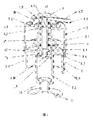
- Figure 1 is a cross-sectional view showing a first embodiment of the present invention
- Figure 2 is an exploded view of a second embodiment of the present invention.
- FIG. 4 and FIG. 5 are partial views of an elastic film and a check valve according to a second embodiment of the present invention.
- Figure 6 is a cross-sectional view showing a third embodiment of the present invention.
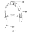
- Figure 7 is a cross-sectional view of the snap connection of the present invention.
- the foam pump comprises a cap (2), a spray head (3), a piston (2.4) and a hollow plunger (1).
- the liquid cylinder (2.1) is integrally extended downward from the bottle cap (2), the piston (2.4) is disposed by the outer edge of the cap (2), and the inner wall of the nozzle (3) becomes a cylinder (3.1), and the piston (2.4) Forming a dynamic seal to the cylinder (3.1);
- the upper edge of the cap (2) and the lower edge of the spray head (3) have a first buckle position (13), and the lower edge of the spray head (3) is divided into a plurality of small buckle positions (3.4) to increase the buckle position.
- Sex in order to facilitate the entry of the core during the production of the plastic and the opening of the cap when assembling, while the small buckle (3.4) of the nozzle can be tightly along the corresponding chute (2.5) of the side wall of the cap. Sliding to reduce the lateral oscillation of the nozzle;
- the nozzle (3) has an air outlet (3.2) in the center; the nozzle (3) has an air inlet (3.3);
- the hollow pressing rod (1) becomes a separate member, and the hollow pressing rod (1) has two discs (1.6) and (1.7) at the lower end, and the hollow pressing rod (1) between the two discs has a lateral hole (1.5). And arranged with an elastic ring (15), the elastic ring (15) can act as a liquid outlet check valve for the lateral hole (1.5) when the hollow pressing rod (1) slides up and down; the elastic ring ( The outer edge of 15) forms a dynamic seal with the cylinder (2.1) of the cap (2);
- the hollow pressing rod (1) has an upper disc (1.3), and a conical spring (12) is mounted between the cap (2) and the upper disc (1.3) at the cap (2) and the nozzle (4) When the first buckle position (13) is just engaged, the conical spring (12) forms an initial pressure, so that the upper disc (1.3) closes the air outlet (3.2) of the spray head (3);
- the upper end (1.2) of the upper disc (1.3) passes through the circular hole (3.2) of the spray head (3), and then the nozzle (4.1) of the nozzle (4) is inserted and the second buckle position (14) is set to make the nozzle (4)
- the bottom surface of the nozzle is separated from the surface of the nozzle (3) by a distance of 2 mm; the buckles are not easy to escape from each other.
- the nozzle (4) and the nozzle (3) are not sealed to form a floating raft.
- the gap is zeroed (disappeared), and the bottom surface of the nozzle (4) is moved down to the surface of the nozzle (3). Seal and close the air inlet (3.3) on the spray head (3).
- the hollow pressure rod (1) moves down while the upper disc (1.3) opens the air outlet (3.2) of the spray head (3), also making the elastic ring (15) Relatively upward, open the lateral hole (1.5) of the hollow plunger (1) to discharge the liquid into the mixing chamber; the piston (2.4) of the cap (2) also passes air through the air outlet (3.2) , the semicircular groove (1.4) between the upper end of the hollow pressure rod (1.2) and the nozzle nozzle (4.1) is discharged into the mixing chamber, the air and the liquid are foamed, and the foam is discharged from the nozzle opening (4.2);
- the metal spring (12) rebounds, causing the hollow pressing rod (1) to rise, the gap to recover, and the air inlet (3.3) of the nozzle (3) is opened, and the hollow pressing rod (1) is rounded.
- the disc (1.3) moves up the closed air outlet (3.2), and also moves the elastic ring (15) relatively downward, closing the lateral hole (1.5) of the hollow pressing rod (1); the hollow pressing rod drives the elastic ring (15)
- the rise causes the cylinder to form a negative pressure to draw the liquid; at the same time, the piston (2.4) in the spray head (3) draws the external gas from the air inlet (3.3) into the cylinder (3.1).
- the floating gap of the nozzle (4) and the nozzle (3) plays a check valve function of the switch air inlet and outlet check valve and the liquid outlet under the joint action of the metal spring (12) and the hollow pressure rod (1). . Since the stroke and the resistance involved in the floating of the nozzle (4) are small, the inlet and outlet passages of the air are quickly opened or closed, and the lateral hole (1.5) of the hollow pressing rod (1) is also quickly opened.
- the metal spring (12) is a conical spring, and the spring diameter of each turn is larger than the previous one, so the spring can be flattened and its height is equal to the wire diameter; the lower end of the metal spring (12) is in the bottle.
- the upper end of the metal spring (12) presses the upper disc (1.3) of the hollow pressing rod (1), so that the hollow pressing rod (1) can immediately follow the metal spring (12) under any circumstances. Action to ensure the effectiveness of the air outlet switch;
- the inner space of the nozzle nozzle (4.1) is the mixing chamber, and the hollow pressure rod port (1.2) has an arranged semicircular groove (1.4) for the passage of air into the mixing chamber.
- the air enters the bottom of the mixing chamber from the upper part of the port, and the air has been grooved. Divided into small airflow, can directly blister into the liquid, and the air bubble enters the foaming net (9) to divide, which increases the divided path, so it is expected to obtain a more delicate foam;
- the foam pump When the foam pump is placed, a small amount of undischarged liquid and foam remains, and some of it remains at the bottom of the mixing chamber. Since the port is set at a height from the bottom, the liquid does not overflow the port.
- the diameter of the circular groove is small, and the arranged groove does not cause too much resistance to the air entering the mixing chamber, but the small groove is for the liquid, but because of the capillary phenomenon of the liquid (surface tension), even if the bottle is poured, the mixing chamber is inside. The liquid does not easily flow out, especially the more viscous liquid.
- the liquid outlet check valve (12) of the foam pump may also be disposed in the mixing chamber, above the liquid outlet, preferably as a loose-leaf check valve;
- a mixing chamber has a foaming net (9), and a liquid inlet check valve (10) is arranged at the bottom of the liquid cylinder;
- the elastic ring (15) has the function of a conventional piston and must form a dynamic seal on the cylinder, so it is necessary to overcome the frictional resistance. If the elastic ring is changed into an elastic film or an elastic bag, there is no requirement for dynamic sealing of the liquid cylinder wall, and no friction is generated on the liquid cylinder.
- the beneficial effect is that a metal spring with a thin wire diameter can be used as the elastic returning element. .
- the liquid cylinder (2.1) is integrally formed by the bottle cap (2) extending downward, and is obtained by one injection molding.
- the bottle cap (2) has a round wall (2.2), and the elastic film (7) has a thick seal.
- the surface is mounted on the inner circular wall (2.2), and the circular wall (2.2) can be used to overcome the horizontal component force of the elastic film (7) during elongation deformation, and the vertical component force when the elastic film (7) is elongated is used to increase Sealing pressure.
- the piston (2.4) is arranged by the outer edge of the cap (2), the inner wall of the nozzle (3) becomes the cylinder (3.1), the piston (2.4) forms a dynamic seal against the cylinder (3.1); the upper edge of the cap (2) and There is a first buckle position (13) between the lower edge of the nozzle (3), the lower edge of the nozzle (3) is divided into a plurality of small buckle positions (3.4), and the buckle position (3.4) can be along the bottle cover (2)
- the corresponding sliding groove (2.5) of the side wall surface is relatively tightly sliding;
- the lower end (1.1) of the hollow compression rod (1) is tightly inserted downwardly into the outlet of the elastic membrane (7) (7.2);
- the nozzle (3) has an air outlet (3.2) in the center, the hollow compression rod (1) has an upper disc (1.3), the hollow compression rod (1) passes upward through the air outlet (3.2), the circular hole (3.2) and the hollow compression rod
- the annular gap of (1) becomes the outlet passage of the air;
- the upper end opening (1.2) of the hollow compression rod is inserted into the nozzle nozzle (4.1), and the second buckle position (14) is arranged, so that the bottom surface of the nozzle (4) leaves the nozzle (3)
- the surface has a gap of about 2 mm, which makes it difficult for each other to escape; under the restriction of the first buckle (8), when the hollow pressing rod (1) forms an initial pressure on the elastic film (7), the upper disc (1.3)
- the ring gap to the air outlet (3.2) is closed;
- the nozzle (4) and the nozzle (3) are not sealed to form a floating raft.
- the gap is zeroed (disappeared), and the bottom surface of the nozzle (4) is moved down to the surface of the nozzle (3) to form a seal.
- the floating gap between the nozzle (4) and the nozzle (3) acts as a check valve for the air inlet and outlet of the switch under the joint action of the elastic membrane (7) and the hollow pressure rod (1).
- a loose-leaf check valve (12) can be arranged above the liquid outlet in the mixing chamber; a liquid inlet check valve (10) is arranged at the bottom of the cylinder (2.1) of the bottle cap (2) ;
- the intermediate sealing surface and the annular mounting surface are at an angle, and it is not difficult to obtain a one-way valve having an initial pressure on the sealing surface, which can be installed in the bottom of the cylinder or in the mixing chamber, the initial pressure. It can resist the outflow of liquid when the bottle is tilted.
- a balancing orifice (2.3) is placed on the cap opposite the flap (11) of the cap seal.
- the elastic film can be made of elastomers such as TPE, TPU, TPR, etc., and the above elastomers can provide an elongation of more than 200-300% and an elongation at break of more than 600%, since the stroke involved is generally 15-20 mm, From the pressing surface of the elastic film to the length of the sealing surface, it is sufficient to provide sufficient elongation requirements of 7-8 mm. It is apparent that there is no difficulty in designing the length of the elastic film (1) in the liquid cylinder of the cap, since the liquid cylinder of the conventional foam pump is about 40 mm (for configuring the stroke of the piston and the metal spring); when the elastic film is elongated Without contact with the cylinder wall, it does not constitute frictional resistance.
- elastomers such as TPE, TPU, TPR, etc.
- the resilience is also related to the thickness of the elastic film and the properties of the elastic material, which provides a wide range of possibilities for selection and design.
- the elastic bladder can also be used for elastic restoring elements, such as the following embodiments;
- the elastic bladder (12) is sealed as a cylinder member to the cylinder (2.1) of the bottle cap (2), and the sealing effect on the bottom of the cylinder is increased under the pressure of the pressure bar (1), and the cap (2) with a piston (2.4);
- the lower end of the elastic bladder (12) can be designed with an inlet check valve (12.1).
- the check valve (12.1) In order to meet the requirements of the core die, the check valve (12.1) must be parallel to the center line of the elastic bladder. The valve is pressed into the recess of the bottom surface of the elastic bag along the bending position to form a tight connection; the depth of the design notch is equal to the thickness of the one-way valve, and it is not difficult to obtain a flat sealing surface; changing the angle of the notch surface relative to the sealing surface is not It is difficult to obtain the initial sealing pressure of the check valve (12.1) to the cylinder inlet.
- Figure 6 shows a longer nozzle interface that forms an elongated mixing chamber that facilitates the separation of the foam in the turbulent flow and is expected to eliminate the foam web.
- the upper end of the elastic bladder (12) (12.2) has a liquid outlet check valve punched by a punching knife; or the loose-leaf check valve is disposed in the mixing chamber, above the liquid outlet;
- the elastic membrane or the elastic bladder acts as a liquid pump, and the liquid discharge amount is independent of the diameter of the liquid cylinder. Selecting the larger diameter cylinder body can reduce or avoid the friction of the elastomer body on the cylinder wall, and also facilitate the installation of the liquid inlet bill.
- the valve also helps to reduce the suction resistance of the liquid.
- the buckle connection between the components of the foam pump is required to prevent the escape, and the lateral swing of the spray head can be reduced. It is also advantageous to make the line contact of the cylinder piston to the cylinder body into surface contact.
- the foam pump is still characterized in that the outer wall of the cap is used to perform the stroke of the nozzle, thereby greatly reducing the height of the entire foam pump, but still has a shape substantially similar to that of a conventional foam pump, and thus is better adapted to some consumers. Aesthetics and usage habits.
- the cross-fusion of pump component functions reduces the number of components of the pump and reduces the height of the pump, effectively providing conditions for increasing piston travel.
- the whole pump is made of only two kinds of synthetic resin, no spring, easy to recycle environmentally.
- TPE and PP have compatibility, and even can be mixed and recycled with PP bottles to obtain a certain PP modified resin.
- the upper disc of the hollow pressing rod can be refined into a buckle position, and the movable snap sealing surface is used to form a switch, but a precision mold is required for production, which in turn increases the cost of the mold and is not worth the loss;
Landscapes
- Engineering & Computer Science (AREA)
- Mechanical Engineering (AREA)
- General Engineering & Computer Science (AREA)
- Closures For Containers (AREA)
- Containers And Packaging Bodies Having A Special Means To Remove Contents (AREA)
Abstract
将瓶盖外缘变成活塞,使活塞在喷头内壁构成的气缸内形成动态密封,成为空气泵的主体;液缸由瓶盖向下延伸而得,有液缸的泵体构件连接空心压杆到喷嘴的混合腔,成为液体泵的主体;空心压杆有圆盘,圆盘上部穿过喷头的空气出口,利用卡扣插接于喷嘴接管,圆盘形成了对气体出口的开关;设计卡扣的位置使喷嘴和喷头有一个小间隙,形成了喷嘴的浮筏功能,就可以在按压喷嘴时,联动打开或关闭空气的进出口和液体出口;弹性膜或弹性囊成为泡沫泵的弹性复位元件,弹性膜或弹性囊还可以配置液体出口单向阀,就使泡沫泵的构件及其装配工作大大减少,成本效益进一步增加。
Description
本发明涉及家用泵头技术领域,更具体地说,特别涉及一种泡沫泵及其优化。
现有的泡沫泵安装在瓶盖里,再加引管和喷头配置好供应市场,多用于洗手杀菌用途,大多结构精密、复杂,成本较高,从而限制了其广泛的使用。
市售的泡沫泵一般是用串联的两个活塞分别泵送液体和空气进入混合腔发泡的,由于活塞对缸壁的密封要求,使摩擦力增大,所以必须使用金属弹簧实现回弹。为了得到较大的气液比,使用了较大直径的空气缸使瓶盖直径变大了。如某市售泡沫泵经测量外盖直径45mm,足足比35mm常规沐浴瓶外盖大了10mm,显然不能安装泡沫泵于常规沐浴瓶上。该泡沫泵的空气活塞的直径32mm,其实比常规沐浴瓶外盖还小,因此将活塞安装于瓶盖上就能使用常规的沐浴瓶子,以36mm活塞直径计算还能获得多26%的空气量。
中国发明专利CN201610268510.6《活塞泵喷头》给出了将活塞安装于喷头内,并将瓶盖变成活塞的泡沫泵,就大大的减少了泡沫泵的构件,达到了增加排气量的效果。
该发明管路简单,不需要精密模具,但是仍然和常规泡沫泵一样使用两个活塞,阻力较大,必须使用复位弹簧,不利于环保回收操作,同时仍然需要使用空气及液体的进出口单向阀,增加了装配成本。
为了解决以上不足,本发明提出了喷嘴的浮筏结构就能解决气体进出口单向阀的问题,而使用弹性膜或弹性囊作为复位元件就能够减少一个活塞和金属弹簧,加上弹性膜或弹性囊出口可以用冲刀冲出单向阀,综合成本更低了。
发明内容
喷头泡沫泵,包括瓶盖、喷头、喷嘴、空心压杆及弹性复位元件,瓶盖、喷头、喷嘴依次向上安装;
瓶盖中心向下延伸有液缸,液缸底部安装有液体进口单向阀;
瓶盖的外缘有活塞构造,瓶盖能进入喷头内,瓶盖的活塞与喷内壁形成动态密封,喷头的行程配置于瓶盖的外壁,构成了空气泵的主体;
瓶盖的上部外侧面与所述喷头下部内侧面设置有第一扣位构造,防止彼此脱出并减少侧向摆动;
喷头中心有连接喷嘴的空气出口,空心压杆从圆孔中穿过,空心压杆设置有上部圆盘对该圆孔形成开关;空心压杆的上端插接喷嘴接管并设置有第二扣位,喷嘴接管内部形成混合腔,在液缸里,空心压杆下端配置了泵体构件如弹性圆环(O圈)、弹性膜或弹性囊,构成了液体泵的主体;
喷头上还设置有空气进口;
第二扣位的特征在于使喷嘴与喷头间形成间隙,形成浮筏状态:当压迫喷嘴,间隙消失,喷嘴底面下移至喷头表面形成密封,并将喷头上的空气进口关闭,同时空心压杆带动上部圆盘下移,打开喷头进入喷嘴的空气出口;当松开喷嘴,弹性复位元件回弹,空心压杆上移,其上部圆盘封闭空气出口, 同时喷嘴的底面上升,间隙恢复,打开喷头上的空气进口,因此形成了空气进出口的单向阀功能。即浮筏特征提供了小行程用于空气进出口通道的开启和封闭,在联动的时序上完全和泵气吸气的要求相一致;
当喷嘴继续下压,液体和空气进入混合腔中,形成泡沫,经喷嘴口流出;当喷嘴下压结束,弹性复位元件回弹,浮筏的小行程首先启动,喷嘴上移,打开空气进口,活塞相对下移吸入空气,实现了空气泵的吸气功能,同时液缸的泵体构件使液缸吸入液体,实现了液体泵的吸液功能;
弹性复位元件安装于空心压杆上部圆盘与瓶盖之间;
一个常规方案,弹性复位元件为金属圆锥弹簧,液缸的泵体构件为弹性圆环;液体出口单向阀安装于混合腔内;
一优选方案是,弹性复位元件和液缸的泵体构件为弹性膜,密封安装于瓶盖配置的液缸中;
另一优选方案,弹性复位元件和液缸的泵体构件为弹性囊,弹性囊密封安装于瓶盖配置的液缸中;
进一步,液体出口单向阀为“+”字单向阀,在弹性膜或弹性囊的弧面中央用冲刀开出,并密封安装于空心压杆的下端部。
本发明对泡沫泵的改进包含三个内容:
一).设置喷嘴对喷头的浮筏结构,实现气体的进出口和液体出口单向阀的配置;
二).用弹性膜或弹性囊作为泡沫泵的弹性复位元件,可以取消金属弹簧;
三).喷头的扣位被分割成多个小扣位,其能沿着瓶盖面对应的滑槽较紧密的滑动,就能大大地减少喷头的侧向摆动。
本发明的泡沫泵结构简单,成本低廉。
用弹性囊代替弹性膜做复位元件,还能复合出具有液体进口单向阀的构造。
通过对实施例附图的描述,可以更好地得理解本发明的技术特征,但是实施例并不构成对本发明的限制。
图1为本发明的实施例一的剖视图;
[根据细则26改正13.06.2018]
图2为本发明的实施例二的分解图;
图2为本发明的实施例二的分解图;
[根据细则26改正13.06.2018]
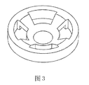
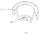
图3、图4和图5为本发明实施例二中弹性膜及单向阀的部分视图;
图3、图4和图5为本发明实施例二中弹性膜及单向阀的部分视图;
[根据细则26改正13.06.2018]
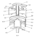
图6为本发明的实施例三的剖视图;
图6为本发明的实施例三的剖视图;
[根据细则26改正13.06.2018]
图7为本发明的卡扣连接的剖视图;
图7为本发明的卡扣连接的剖视图;
实施例一
参阅图1,泡沫泵包含瓶盖(2)、喷头(3)、活塞(2.4)和空心压杆(1)。液缸(2.1)由瓶盖(2)向下延伸而成一体,活塞(2.4)由瓶盖(2)的外缘来配置,喷头(3)的内壁成为气缸(3.1),活塞(2.4)对气缸(3.1)形成动态密封;
瓶盖(2)的上缘和喷头(3)的下缘有第一扣位(13),喷头(3)的下缘被分割成多个小扣位(3.4),以增加扣位的挠性,以便于在塑料生产时,模芯的出模和装配时瓶盖扣位的进入,同时喷头的小扣位(3.4)能沿着瓶盖侧壁 面的对应滑槽(2.5)较紧密的滑动,以减少喷头的侧向摆动;
喷头(3)中央有空气出口(3.2);喷头(3)上有空气进口(3.3);
空心压杆(1)成为独立构件,空心压杆(1)下端有两个圆盘(1.6)、(1.7),在两个圆盘之间的空心压杆(1)有侧向孔(1.5),并配置了弹性圆环(15),在空心压杆(1)上下滑动时,弹性圆环(15)能对侧向孔(1.5)起液体出口单向阀的作用;弹性圆环(15)的外缘与瓶盖(2)的缸体(2.1)形成动态密封;
空心压杆(1)有上部圆盘(1.3),有锥形弹簧(12)安装于瓶盖(2)和上部圆盘(1.3)之间,在瓶盖(2)和喷嘴(4)的第一扣位(13)刚刚扣入时,锥形弹簧(12)形成初始压力,使上部圆盘(1.3)封闭喷头(3)的空气出口(3.2);
上部圆盘(1.3)的上端(1.2)穿过喷头(3)的圆孔(3.2),再插接喷嘴(4)的接管(4.1)并设置第二扣位(14),使喷嘴(4)的底面离开喷头(3)表面有2mm的距离;该扣位令彼此不易脱出。
喷嘴(4)和喷头(3)之间不密封,以形成浮筏特征,当开始压迫喷嘴(4),间隙归零(消失),喷嘴(4)的底面下移至喷头(3)表面形成密封,并关闭喷头(3)上的空气进口(3.3),空心压杆(1)的下移同时使上部圆盘(1.3)打开喷头(3)的空气出口(3.2),也使弹性圆环(15)相对上移,打开空心压杆(1)的侧向孔(1.5),将液体排入混合腔中;瓶盖(2)的活塞(2.4)也同时将空气经空气出口(3.2),经空心压杆上端(1.2)与喷嘴接管(4.1)间的半圆凹槽(1.4)排入混合腔中,空气和液体起泡,泡沫从喷嘴口(4.2)排出;
当喷嘴(4)没有压迫,金属弹簧(12)反弹,使空心压杆(1)上升,间隙恢复,使喷头(3)的空气进口(3.3)打开,同时使空心压杆(1)的圆盘(1.3)上移封闭空气出口(3.2),也使弹性圆环(15)相对下移,关闭空心压杆(1)的侧向孔(1.5);空心压杆带动弹性圆环(15)上升使液缸形成负压吸入液体;同时喷头(3)内的活塞(2.4)从空气进口(3.3)吸入外部气体到气缸(3.1)中。
可见喷嘴(4)和喷头(3)的浮筏间隙,在金属弹簧(12)和空心压杆(1)的联动作用下,起了开关空气进出口单向阀和液体出口的单向阀作用。由于喷嘴(4)的浮筏涉及的行程和阻力都很小,就会迅速地打开或封闭空气的进出口通道,同时也使空心压杆(1)的侧向孔(1.5)迅速打开。
图中显示金属弹簧(12)为圆锥弹簧,每一圈的弹簧直径比上一圈大一个线径,因此弹簧能压成扁平状,其高度等于线径;金属弹簧(12)的下端在瓶盖(2)上表面,金属弹簧(12)的上端压迫空心压杆(1)的上部圆盘(1.3),就能在任何情况下,让空心压杆(1)即时随金属弹簧(12)动作,保证空气出口开关的有效性;
喷嘴接管(4.1)的内空间就是混合腔,空心压杆端口(1.2)有排列的半圆凹槽(1.4)为空气进入混合腔的通道,空气由端口上部进入混合腔底部,空气已经被凹槽分割成小气流,能直接鼓入液体中起泡,空气泡再进入发泡网(9)分割,增加了被分割的路径,因此有望获得更加细腻的泡沫;
当放置泡沫泵时,残留未排出的少量液体及泡沫,部分会保留在混合腔底部,由于端口离底部设置了一个高度,所以液体不至于溢出端口外。圆凹槽的直径很小,排列的凹槽对空气进入混合腔不会构成太大的阻力,但是小 凹槽对于液体,却因为液体的毛细现象(表面张力),即使瓶子倾倒,混合腔内的液体也不会轻易流出,特别是较粘稠的液体。
泡沫泵的液体出口单向阀(12)也可以配置于混合腔内,液体出口的上方,优选为活页单向阀;
混合腔内有发泡网(9),液缸底配置液体进口单向阀(10);
为了平衡瓶子内空间的压力,在瓶盖上有平衡小孔(2.3)与瓶口密封圈的活页(11)相对。
弹性圆环(15)有类似常规活塞的作用,必须对液缸形成动态密封,因此需要克服摩擦阻力。如果将弹性圆环改成弹性膜或弹性囊,就没有对液缸壁动态密封的要求,就不会对液缸产生摩擦,有益的效果是可以用较细线径的金属弹簧作为弹性复位元件。
实际上,通过加大弹性膜或弹性囊的厚度和弹性,就可以直接成为弹性复位元件,就可以取消金属弹簧了。如以下实施例:
实施例二
[根据细则26改正13.06.2018]
参阅图2,液缸(2.1)由瓶盖(2)向下延伸而成一体,一次注塑而得,瓶盖(2)上有圆壁(2.2),弹性膜(7)有较厚的密封面安装于内圆壁(2.2)上,就能利用圆壁(2.2)来克服弹性膜(7)伸长变形时的水平分力,利用弹性膜(7)伸长时的垂直分力来增加密封压力。
参阅图2,液缸(2.1)由瓶盖(2)向下延伸而成一体,一次注塑而得,瓶盖(2)上有圆壁(2.2),弹性膜(7)有较厚的密封面安装于内圆壁(2.2)上,就能利用圆壁(2.2)来克服弹性膜(7)伸长变形时的水平分力,利用弹性膜(7)伸长时的垂直分力来增加密封压力。
活塞(2.4)由瓶盖(2)的外缘来配置,喷头(3)的内壁成为气缸(3.1),活塞(2.4)对气缸(3.1)形成动态密封;瓶盖(2)的上缘和喷头(3)的下缘之间有第一扣位(13),喷头(3)下缘被分割成多个小扣位(3.4),扣位(3.4)能地沿着瓶盖(2)侧壁面的对应滑槽(2.5)较紧密的滑动;
空心压杆(1)下端(1.1)向下紧密插入弹性膜(7)的出口(7.2);
喷头(3)中央有空气出口(3.2),空心压杆(1)有上部圆盘(1.3),空心压杆(1)向上穿过空气出口(3.2),圆孔(3.2)与空心压杆(1)的环隙成为空气的出口通道;空心压杆的上端开口(1.2)插接于喷嘴接管(4.1),并配置第二扣位(14),使喷嘴(4)底面离开喷头(3)表面有约2mm的间隙,该扣位令彼此不易脱出;在第一扣位(8)的限制下,空心压杆(1)对弹性膜(7)形成初始压力时,上部圆盘(1.3)对空气出口(3.2)的环隙成关闭状态;
喷嘴(4)和喷头(3)之间不密封,以形成浮筏特征,当压迫喷嘴(4),间隙归零(消失),喷嘴(4)底面下移至喷头(3)表面形成密封,并关闭喷头(3)上的空气进口(3.3),同时空心压杆(1)的上部圆盘(1.3)下移,打开喷头(3)的空气出口(3.2);继续按压喷嘴(4),瓶盖活塞(2.4)将空气经空气出口(3.2),经空心压杆上端(1.2)与喷嘴接管(4.1)间的半圆凹槽(1.4)进入混合腔中;同时空心压杆(1)的下端开口(1.1)压迫弹性膜(7)将液体经其出口单向阀(7.2)排入混合腔中起泡,泡沫从喷嘴口(4.2)排出;
当喷嘴(4)没有压迫,弹性膜(7)反弹,弹性膜(7)包围的缸体空间形成负压,便吸入液体;弹性膜(7)并使空心压杆(1)的上部圆盘(1.3)上移,封闭空气出口(3.2),同时使喷头(3)与喷嘴(4)的间隙恢复,喷头(3)的空气进口(3.3)被打开,气缸活塞(2.4)吸入空气到气缸(3.1)中。
可见喷嘴(4)和喷头(3)的浮筏间隙,在弹性膜(7)和空心压杆(1) 的联动作用下,起了开关空气进出口单向阀作用。
混合腔内有发泡网(9),混合腔内液体出口上方可以配置活页式单向阀(12);瓶盖(2)的缸体(2.1)底部配置了液体进口单向阀(10);
[根据细则26改正13.06.2018]
如图3及图4,中间的密封面与环状安装面成某一个角度,都不难获得对密封面具有初始压力的单向阀,可以安装于液缸底部或混合腔内,该初始压力可以抵御瓶子倾侧时液体的流出。
如图3及图4,中间的密封面与环状安装面成某一个角度,都不难获得对密封面具有初始压力的单向阀,可以安装于液缸底部或混合腔内,该初始压力可以抵御瓶子倾侧时液体的流出。
[根据细则26改正13.06.2018]
如图5,在弹性膜的上端(7.2)的弧面上,用冲刀冲出“+”字口,就能形成互为90°的4个活页的液体出口单向阀,只是其以彼此的切口作为密封面。上述视图仅为便于理解发明的示意性视图,在真实情况中,“+”字刀为无余量的冲切,实际上没有间隙。
如图5,在弹性膜的上端(7.2)的弧面上,用冲刀冲出“+”字口,就能形成互为90°的4个活页的液体出口单向阀,只是其以彼此的切口作为密封面。上述视图仅为便于理解发明的示意性视图,在真实情况中,“+”字刀为无余量的冲切,实际上没有间隙。
例如在奶瓶的奶嘴上就有约3mm的“+”字刀口,在奶瓶倒置时可以防止牛奶流出。
为了平衡瓶子内空间的压力,在瓶盖上有平衡小孔(2.3)与瓶盖密封圈的活页(11)相对。
弹性膜可以用TPE、TPU、TPR等弹性体制造,上述弹性体均可以提供超过200-300%的伸长率,超过600%的断裂伸长率,因为涉及的行程一般为15-20mm,因此由弹性膜的压迫面到密封面的长度只要7-8mm就能提供足够的伸长要求。在瓶盖的液缸中设计弹性膜(1)的该长度,显然是无任何困难的,因为常规泡沫泵的液缸约40mm(用于配置活塞的行程和金属弹簧);弹性膜伸长时没有和缸体壁接触,不会构成摩擦阻力,随着弹性膜的伸长,应变增大,应力正比增大,也因此提供了足够的回弹力来吸入液体和空气。显然回弹力还与弹性膜的厚度及弹性材料的性能有关,这就为选择和设计提供了广泛的 可能性。
弹性囊也可以用于弹性复位元件,如以下实施例;
实施例三
[根据细则26改正13.06.2018]
参阅图6,图中给出了弹性囊(12)代替弹性膜的泡沫泵。
参阅图6,图中给出了弹性囊(12)代替弹性膜的泡沫泵。
弹性囊(12)作为缸体构件密封安装于瓶盖(2)的缸体(2.1),在压杆(1)的压力下会增加对液缸底的密封效果,瓶盖(2)带活塞(2.4);
[根据细则26改正13.06.2018]
如图7弹性囊(12)下端开口可以设计自带进口单向阀(12.1),为了适应模芯出模的要求,单向阀(12.1)必须和弹性囊的中线平行,装配时将单向阀沿折弯位压入弹性囊底面的凹口中形成紧密连接;设计凹口的深度等于单向阀的厚度,就不难获得平整的密封面;改变凹口面相对于密封面的角度,就不难获得单向阀(12.1)对液缸进口的初始密封压力。
如图7弹性囊(12)下端开口可以设计自带进口单向阀(12.1),为了适应模芯出模的要求,单向阀(12.1)必须和弹性囊的中线平行,装配时将单向阀沿折弯位压入弹性囊底面的凹口中形成紧密连接;设计凹口的深度等于单向阀的厚度,就不难获得平整的密封面;改变凹口面相对于密封面的角度,就不难获得单向阀(12.1)对液缸进口的初始密封压力。
[根据细则26改正13.06.2018]
图6给出了较长的喷嘴接口,形成细长的混合腔,有利于泡沫在湍流的流动中被分割,有望取消泡沫网。
图6给出了较长的喷嘴接口,形成细长的混合腔,有利于泡沫在湍流的流动中被分割,有望取消泡沫网。
空心压杆(1)与喷嘴(4)等的配置关系,仍然保留与实施例一、例二相同的浮筏的特征;
弹性囊(12)上端(12.2)有冲刀冲切的液体出口单向阀;或者活页单向阀配置于混合腔内,液体出口上方;
为了平衡瓶子内空间的压力,在瓶盖上有平衡小孔(3.3)与瓶口密封圈(11)的活页相对。
需要指出,弹性膜或弹性囊作为液体泵的作用,其排液量与液缸的直径无关,选择较大直径的缸体可以减少或避免弹性体对缸壁的摩擦,也便于安装液体进口单向阀,还有利于减少液体的吸入阻力。
以上实施例中,泡沫泵各构件间需要扣位连接来防止脱出,并能减少喷头的侧向摆动。把气缸活塞对缸体的线接触变成面接触也是有利的。
各实施例中分别给出了不同的扣位形式,在组合塑料玩具中,大量使用了不同的扣位,其属于塑料的常规技术,因此不再详细讨论。
泡沫泵的特征仍然在于利用了瓶盖的外壁实施了喷头的行程,因此大大降低了整个泡沫泵的高度,但是仍然具有和常规泡沫泵大致相似的外形,因此能更好地适应部分消费者的审美观和使用习惯。泵构件功能的交叉融合,使泵的构件数量减少,泵的高度降低了,实际上为增加活塞行程提供了条件。
整个泵只用两种合成树脂制造,没有弹簧,便于环保回收,比如TPE和PP具有相容性,甚至可以和PP瓶子混合回收,获得某种PP改性树脂。
空心压杆的上部圆盘可以细化为扣位,用活动的卡扣密封面形成开关,但是需要精密模具来生产,徒然增加了模具成本,得不偿失;
泡沫泵的单向阀、扣位和泵的安装技术等问题,本行业的相关技术人员能够做出合理的选择,也可以对本发明的各构件的配置做出调整,都将在本发明的保护范围内;各实施例不构成对本发明的限制。
Claims (6)
- 一种喷头泡沫泵,其特征在于,包括瓶盖、喷头、喷嘴、空心压杆及弹性复位元件;所述瓶盖的外缘构成活塞,瓶盖能进入喷头内,所述活塞对喷头内壁形成动态密封,所述喷头其行程配置于瓶盖的外壁,构成了空气泵的主体;所述瓶盖的上缘和所述喷头下缘有第一扣位;所述的瓶盖还配置了液缸,液缸配置了泵体构件,液缸底安装有液体进口单向阀;所述喷头中心有空气出口,空心压杆从中穿过,空心压杆有上部圆盘对所述空气出口的通道形成开关;所述空心压杆的上端通过第二扣位插接所述喷嘴接管,所述喷嘴接管内有混合腔;所述喷头还有空气进口;所述第二扣位使喷嘴离开喷头一个间隙,形成浮筏特征:当压迫所述喷嘴,间隙消失,喷嘴底面下移至喷头表面形成密封并将喷头上的空气进口关闭,同时所述的空心压杆的上部圆盘打开喷头的空气出口;当松开所述喷嘴,所述弹性复位元件回弹,喷嘴上移,间隙恢复,打开所述空气进口,形成了空气进口单向阀;同时所述的空心压杆的上部圆盘封闭空气出口,形成了空气的出口单向阀;所述空心压杆的下端连接安装液缸的泵体构件,构成了液体泵的主体。
- 根据权利要求1所述的喷头泡沫泵,其特征在于所述弹性复位元件是金属弹簧,安装于瓶盖与空心压杆的上部圆盘之间;所述液缸的泵体构件为弹性圆环,对液缸形成动态密封,其安装于所述空心压杆下缘的两个圆盘之间,所述空心压杆有侧向孔,当压迫所述喷嘴,所述 弹性圆环对所述侧向孔形成液体出口单向阀的作用;所述液体出口单向阀也可以配置于混合腔内;所述液体进口单向阀为活页单向阀;所述弹性圆环也可以用弹性膜或弹性囊代替。
- 根据权利要求1所述的喷头泡沫泵,其特征在于所述的液缸的泵体构件是弹性膜,密封安装于所述的液缸中,其特征还在于所述弹性膜同时构成了弹性复位元件;所述液体出口单向阀配置于混合腔内,也可以配置在所述弹性膜的弧面中央用冲刀开出的单向阀,并密封安装于所述的空心压杆下端的口部;所述的液体进口单向阀为活页单向阀。
- 根据权利要求1所述的喷头泡沫泵,所述液缸的泵体构件是弹性囊,所述弹性囊安装于瓶盖的液缸中,其特征还在于所述弹性囊同时构成了弹性复位元件;所述的液体出口单向阀配置于混合腔内,也可以配置在所述弹性囊的弧面中央用冲刀开出的单向阀,并密封安装于所述的空心压杆下端的口部;所述的液体进口单向阀为弹性囊自带的活页单向阀。
- 根据权利要求1所述的喷头泡沫泵,所述的第一扣位,其特征在于喷头上的扣位被分割成多个小扣位,所述瓶盖有对应的滑槽,所述的小扣位能紧密地滑动于所述滑槽中。
- 根据权利要求1所述的喷头泡沫泵,其特征在于所述瓶盖上还有平衡小孔与瓶盖密封圈的活页相对。
Priority Applications (2)
| Application Number | Priority Date | Filing Date | Title |
|---|---|---|---|
| EP18802236.2A EP3626648A4 (en) | 2017-05-19 | 2018-05-08 | PUMP FOAM SPRAYER |
| US16/688,041 US11110473B2 (en) | 2017-05-19 | 2019-11-19 | Foam pump sprayer |
Applications Claiming Priority (2)
| Application Number | Priority Date | Filing Date | Title |
|---|---|---|---|
| CN201710359422.1 | 2017-05-19 | ||
| CN201710359422.1A CN107187724B (zh) | 2017-05-19 | 2017-05-19 | 泡沫泵喷头 |
Related Child Applications (1)
| Application Number | Title | Priority Date | Filing Date |
|---|---|---|---|
| US16/688,041 Continuation US11110473B2 (en) | 2017-05-19 | 2019-11-19 | Foam pump sprayer |
Publications (1)
| Publication Number | Publication Date |
|---|---|
| WO2018210160A1 true WO2018210160A1 (zh) | 2018-11-22 |
Family
ID=59874258
Family Applications (1)
| Application Number | Title | Priority Date | Filing Date |
|---|---|---|---|
| PCT/CN2018/086012 Ceased WO2018210160A1 (zh) | 2017-05-19 | 2018-05-08 | 泡沫泵喷头 |
Country Status (4)
| Country | Link |
|---|---|
| US (1) | US11110473B2 (zh) |
| EP (1) | EP3626648A4 (zh) |
| CN (1) | CN107187724B (zh) |
| WO (1) | WO2018210160A1 (zh) |
Families Citing this family (16)
| Publication number | Priority date | Publication date | Assignee | Title |
|---|---|---|---|---|
| CN107187724B (zh) * | 2017-05-19 | 2019-08-23 | 钟竞铮 | 泡沫泵喷头 |
| CN108516205A (zh) * | 2017-10-10 | 2018-09-11 | 金华知产婺源信息技术有限公司 | 一种无储式按压包装瓶 |
| CN110406790A (zh) * | 2019-07-12 | 2019-11-05 | 上海升村包装材料有限公司 | 一种环保型喷泵 |
| CN110027795B (zh) * | 2019-05-22 | 2023-12-26 | 安吉鲁沃夫生物科技有限公司 | 一种泡沫发生瓶盖及泡沫发生瓶 |
| CN212501863U (zh) * | 2020-06-05 | 2021-02-09 | 宁波市舜德医疗科技有限公司 | 一种全塑料液体分配器 |
| JP2022011373A (ja) * | 2020-06-30 | 2022-01-17 | 花王株式会社 | ポンプ装置 |
| JP2022011331A (ja) * | 2020-06-30 | 2022-01-17 | 株式会社吉野工業所 | 吐出器 |
| CN111826833A (zh) * | 2020-07-03 | 2020-10-27 | 董显聪 | 一种连衣裙原布料除臭装置 |
| CN111840765A (zh) * | 2020-07-17 | 2020-10-30 | 李霞 | 耳鼻喉科专用便携式喷药器 |
| CN112093264A (zh) * | 2020-09-11 | 2020-12-18 | 中山市美捷时包装制品有限公司 | 一种环保型泡沫泵 |
| CN112093263A (zh) * | 2020-09-11 | 2020-12-18 | 中山市美捷时包装制品有限公司 | 一种环保型泡沫泵泵芯 |
| CN113002974B (zh) * | 2021-04-21 | 2024-04-26 | 上海英宇包装科技有限公司 | 乳液双料出液容器 |
| CN113559403B (zh) * | 2021-08-31 | 2023-04-25 | 沃万珑 | 一种可调节给药量的喷剂瓶 |
| JP7793261B2 (ja) * | 2022-01-31 | 2026-01-05 | 株式会社吉野工業所 | 泡噴出容器 |
| CN217696346U (zh) * | 2022-05-09 | 2022-11-01 | 中山市美捷时包装制品有限公司 | 一种全塑泡沫泵结构 |
| CN119969869A (zh) * | 2025-03-27 | 2025-05-13 | 厦门拓铂科技有限公司 | 一种稳定输出泡沫水的泡沫生成装置和一种卫浴装置 |
Citations (6)
| Publication number | Priority date | Publication date | Assignee | Title |
|---|---|---|---|---|
| US20070295754A1 (en) * | 2005-08-16 | 2007-12-27 | Tourigny Jay S | Actuators for fluid-dispenser containers and containers including such actuators |
| CN201292924Y (zh) * | 2008-11-06 | 2009-08-19 | 屠旭峰 | 一种泡沫泵 |
| CN105083730A (zh) * | 2015-06-26 | 2015-11-25 | 钟竞铮 | 弹性囊泡沫泵 |
| CN105564802A (zh) * | 2015-12-18 | 2016-05-11 | 钟竞铮 | 一种活塞泵喷头 |
| CN106115062A (zh) * | 2015-05-06 | 2016-11-16 | 钟竞铮 | 活塞泵喷头 |
| CN107187724A (zh) * | 2017-05-19 | 2017-09-22 | 钟竞铮 | 泡沫泵喷头 |
Family Cites Families (17)
| Publication number | Priority date | Publication date | Assignee | Title |
|---|---|---|---|---|
| JPH10165501A (ja) * | 1996-12-12 | 1998-06-23 | Kao Corp | 吐出容器、口腔用組成物及び口腔用組成物の使用方法 |
| US6612468B2 (en) * | 2000-09-15 | 2003-09-02 | Rieke Corporation | Dispenser pumps |
| NL1022633C2 (nl) * | 2003-02-10 | 2004-08-12 | Keltub B V | Verbeterde schuimvormingseenheid. |
| CA2504989C (en) * | 2005-04-22 | 2013-03-12 | Gotohti.Com Inc. | Stepped pump foam dispenser |
| US7337930B2 (en) * | 2005-05-20 | 2008-03-04 | Gotohti.Com Inc. | Foaming pump with improved air inlet valve |
| US7850048B2 (en) * | 2006-10-23 | 2010-12-14 | Arminak & Associates, Inc. | Foamer pump |
| US20090008412A1 (en) * | 2007-04-10 | 2009-01-08 | Choi Hee Jin | Foam pump dispenser having leakage prevention function against reverse flow |
| US8616414B2 (en) * | 2009-02-09 | 2013-12-31 | Gojo Industries, Inc. | Bellows foam dispenser |
| JP5455206B2 (ja) * | 2009-08-20 | 2014-03-26 | 株式会社三谷バルブ | 泡生成放出ユニット,内容物泡放出ポンプ機構および内容物泡放出ポンプ機構を備えたポンプ式製品 |
| JP5435794B2 (ja) * | 2010-01-22 | 2014-03-05 | 大和製罐株式会社 | ポンプ式泡吐出容器 |
| US20110272432A1 (en) * | 2010-05-10 | 2011-11-10 | Baughman Gary M | Foam dispenser |
| JP2013538103A (ja) * | 2010-09-14 | 2013-10-10 | 上▲海▼上▲栄▼包装技▲術▼有限公司 | ポンプディスペンサー |
| US20120104048A1 (en) * | 2010-10-27 | 2012-05-03 | Hsih Tung Tooling Co.,Ltd. | Foam dispensing device |
| WO2013151320A1 (ko) * | 2012-04-03 | 2013-10-10 | Lee Gwon Haeng | 버블발생부를 갖는 마개구조 |
| CN102691646B (zh) * | 2012-05-16 | 2015-08-26 | 钟竞铮 | 往复式弹性膜泵 |
| JP5972046B2 (ja) * | 2012-05-21 | 2016-08-17 | 株式会社ダイゾー | エアゾール容器用の吐出部材およびそれを用いたエアゾール製品 |
| KR101377602B1 (ko) * | 2012-10-09 | 2014-04-01 | 김태현 | 포밍펌프 |
-
2017
- 2017-05-19 CN CN201710359422.1A patent/CN107187724B/zh not_active Expired - Fee Related
-
2018
- 2018-05-08 WO PCT/CN2018/086012 patent/WO2018210160A1/zh not_active Ceased
- 2018-05-08 EP EP18802236.2A patent/EP3626648A4/en not_active Withdrawn
-
2019
- 2019-11-19 US US16/688,041 patent/US11110473B2/en not_active Expired - Fee Related
Patent Citations (6)
| Publication number | Priority date | Publication date | Assignee | Title |
|---|---|---|---|---|
| US20070295754A1 (en) * | 2005-08-16 | 2007-12-27 | Tourigny Jay S | Actuators for fluid-dispenser containers and containers including such actuators |
| CN201292924Y (zh) * | 2008-11-06 | 2009-08-19 | 屠旭峰 | 一种泡沫泵 |
| CN106115062A (zh) * | 2015-05-06 | 2016-11-16 | 钟竞铮 | 活塞泵喷头 |
| CN105083730A (zh) * | 2015-06-26 | 2015-11-25 | 钟竞铮 | 弹性囊泡沫泵 |
| CN105564802A (zh) * | 2015-12-18 | 2016-05-11 | 钟竞铮 | 一种活塞泵喷头 |
| CN107187724A (zh) * | 2017-05-19 | 2017-09-22 | 钟竞铮 | 泡沫泵喷头 |
Non-Patent Citations (1)
| Title |
|---|
| See also references of EP3626648A4 |
Also Published As
| Publication number | Publication date |
|---|---|
| US11110473B2 (en) | 2021-09-07 |
| EP3626648A4 (en) | 2021-03-03 |
| CN107187724A (zh) | 2017-09-22 |
| EP3626648A1 (en) | 2020-03-25 |
| US20200108406A1 (en) | 2020-04-09 |
| CN107187724B (zh) | 2019-08-23 |
Similar Documents
| Publication | Publication Date | Title |
|---|---|---|
| WO2018210160A1 (zh) | 泡沫泵喷头 | |
| US3486663A (en) | Elastomeric pump and check-valve | |
| US4101057A (en) | Trigger actuated pump | |
| CN104606048B (zh) | 一种眼药水包装瓶 | |
| CN105923253B (zh) | 按压式泡沫泵及其喷量控制方法 | |
| CN2937092Y (zh) | 一种新型液体分配器 | |
| CN209522036U (zh) | 一种按压式容器 | |
| JP5288615B2 (ja) | ポンプ式泡吐出容器 | |
| CN203439425U (zh) | 活塞式沐浴泵 | |
| WO2019144307A1 (zh) | 一种弹性囊泵 | |
| CN102691646B (zh) | 往复式弹性膜泵 | |
| CN205479393U (zh) | 一种按压式开关阀 | |
| KR100995652B1 (ko) | 예압식 저형상 미세 수동 분사펌프 | |
| CN207826999U (zh) | 一种倒喷泡沫泵 | |
| CN105564802B (zh) | 一种活塞泵喷头 | |
| CN210585436U (zh) | 一种出水嘴结构及花洒、顶喷、抽取式喷头 | |
| CN114555485A (zh) | 泵式吐出装置 | |
| WO2013181330A4 (en) | Double acting valve for liquid pumps | |
| CN101272865A (zh) | 止回阀和带有该止回阀的分体式流体设备 | |
| CN106115062B (zh) | 活塞泵喷头 | |
| JP3082899U (ja) | 液体噴出ポンプ | |
| CN206631794U (zh) | 一种即关即停花洒 | |
| CN105197389A (zh) | 泡沫泵 | |
| CN217806440U (zh) | 储压式喷雾泵以及储压式喷雾装置 | |
| JP5000200B2 (ja) | 吐出容器 |
Legal Events
| Date | Code | Title | Description |
|---|---|---|---|
| 121 | Ep: the epo has been informed by wipo that ep was designated in this application |
Ref document number: 18802236 Country of ref document: EP Kind code of ref document: A1 |
|
| NENP | Non-entry into the national phase |
Ref country code: DE |
|
| ENP | Entry into the national phase |
Ref document number: 2018802236 Country of ref document: EP Effective date: 20191219 |