WO2018211984A1 - スピーカアレイ、および信号処理装置 - Google Patents
スピーカアレイ、および信号処理装置 Download PDFInfo
- Publication number
- WO2018211984A1 WO2018211984A1 PCT/JP2018/017485 JP2018017485W WO2018211984A1 WO 2018211984 A1 WO2018211984 A1 WO 2018211984A1 JP 2018017485 W JP2018017485 W JP 2018017485W WO 2018211984 A1 WO2018211984 A1 WO 2018211984A1
- Authority
- WO
- WIPO (PCT)
- Prior art keywords
- speaker
- speakers
- order
- array
- normal
- Prior art date
- Legal status (The legal status is an assumption and is not a legal conclusion. Google has not performed a legal analysis and makes no representation as to the accuracy of the status listed.)
- Ceased
Links
Images




Classifications
-
- H—ELECTRICITY
- H04—ELECTRIC COMMUNICATION TECHNIQUE
- H04R—LOUDSPEAKERS, MICROPHONES, GRAMOPHONE PICK-UPS OR LIKE ACOUSTIC ELECTROMECHANICAL TRANSDUCERS; ELECTRIC HEARING AIDS; PUBLIC ADDRESS SYSTEMS
- H04R1/00—Details of transducers, loudspeakers or microphones
- H04R1/20—Arrangements for obtaining desired frequency or directional characteristics
- H04R1/32—Arrangements for obtaining desired frequency or directional characteristics for obtaining desired directional characteristic only
- H04R1/40—Arrangements for obtaining desired frequency or directional characteristics for obtaining desired directional characteristic only by combining a number of identical transducers
- H04R1/403—Arrangements for obtaining desired frequency or directional characteristics for obtaining desired directional characteristic only by combining a number of identical transducers loud-speakers
-
- H—ELECTRICITY
- H04—ELECTRIC COMMUNICATION TECHNIQUE
- H04R—LOUDSPEAKERS, MICROPHONES, GRAMOPHONE PICK-UPS OR LIKE ACOUSTIC ELECTROMECHANICAL TRANSDUCERS; ELECTRIC HEARING AIDS; PUBLIC ADDRESS SYSTEMS
- H04R29/00—Monitoring arrangements; Testing arrangements
- H04R29/001—Monitoring arrangements; Testing arrangements for loudspeakers
- H04R29/002—Loudspeaker arrays
-
- H—ELECTRICITY
- H04—ELECTRIC COMMUNICATION TECHNIQUE
- H04R—LOUDSPEAKERS, MICROPHONES, GRAMOPHONE PICK-UPS OR LIKE ACOUSTIC ELECTROMECHANICAL TRANSDUCERS; ELECTRIC HEARING AIDS; PUBLIC ADDRESS SYSTEMS
- H04R2201/00—Details of transducers, loudspeakers or microphones covered by H04R1/00 but not provided for in any of its subgroups
- H04R2201/40—Details of arrangements for obtaining desired directional characteristic by combining a number of identical transducers covered by H04R1/40 but not provided for in any of its subgroups
- H04R2201/401—2D or 3D arrays of transducers
-
- H—ELECTRICITY
- H04—ELECTRIC COMMUNICATION TECHNIQUE
- H04R—LOUDSPEAKERS, MICROPHONES, GRAMOPHONE PICK-UPS OR LIKE ACOUSTIC ELECTROMECHANICAL TRANSDUCERS; ELECTRIC HEARING AIDS; PUBLIC ADDRESS SYSTEMS
- H04R2430/00—Signal processing covered by H04R, not provided for in its groups
- H04R2430/03—Synergistic effects of band splitting and sub-band processing
-
- H—ELECTRICITY
- H04—ELECTRIC COMMUNICATION TECHNIQUE
- H04R—LOUDSPEAKERS, MICROPHONES, GRAMOPHONE PICK-UPS OR LIKE ACOUSTIC ELECTROMECHANICAL TRANSDUCERS; ELECTRIC HEARING AIDS; PUBLIC ADDRESS SYSTEMS
- H04R3/00—Circuits for transducers
- H04R3/12—Circuits for transducers for distributing signals to two or more loudspeakers
-
- H—ELECTRICITY
- H04—ELECTRIC COMMUNICATION TECHNIQUE
- H04S—STEREOPHONIC SYSTEMS
- H04S2420/00—Techniques used stereophonic systems covered by H04S but not provided for in its groups
- H04S2420/07—Synergistic effects of band splitting and sub-band processing
-
- H—ELECTRICITY
- H04—ELECTRIC COMMUNICATION TECHNIQUE
- H04S—STEREOPHONIC SYSTEMS
- H04S2420/00—Techniques used stereophonic systems covered by H04S but not provided for in its groups
- H04S2420/11—Application of ambisonics in stereophonic audio systems
-
- H—ELECTRICITY
- H04—ELECTRIC COMMUNICATION TECHNIQUE
- H04S—STEREOPHONIC SYSTEMS
- H04S7/00—Indicating arrangements; Control arrangements, e.g. balance control
- H04S7/30—Control circuits for electronic adaptation of the sound field
Definitions
- the present technology relates to a speaker array and a signal processing device, and more particularly to a speaker array and a signal processing device that can obtain sufficient reproducibility at low cost.
- HOA Higher Order Ambisonics
- more speakers are required to reproduce the sound field in a wider area. This is because it is necessary to control up to higher order components of the signal in the spherical harmonic region and the circular harmonic region of the HOA.
- a method using a speaker array called a higher-order speaker is also known.
- the higher-order speaker is also called HOL (Higher Order Loudspeaker) and is a speaker that can reproduce multiple directivities such as monopoles and dipoles.
- HOL Higher Order Loudspeaker
- annular speaker array or a spherical speaker array obtained by attaching a large number of speaker units in an annular or spherical shape is used as a high-order speaker.
- Non-Patent Document 1 a technique for reproducing a sound field inside and outside a speaker array using a speaker array obtained by arranging a large number of higher-order speakers has been proposed (for example, Non-Patent Document 1). reference).
- the sound field can be reproduced over a wide area, but the high-order speakers are less expensive than ordinary speakers that can reproduce only one directivity. It is expensive and it is not practical to use many high-order speakers.
- the present technology has been made in view of such a situation, and is capable of obtaining sufficient reproducibility at low cost.
- the speaker array according to the first aspect of the present technology includes a plurality of high-order speakers and a plurality of normal speakers, and the wavefronts in the second region outside the first region that can be controlled by the normal speakers.
- the type, number, or arrangement position of the higher-order speakers is determined according to reproducibility.
- the speaker array includes a plurality of high-order speakers and a plurality of normal speakers, and a wavefront in a second region outside the first region that can be controlled by the normal speakers.
- the type, number, or arrangement position of the higher-order speakers is determined according to the reproducibility.
- the signal processing device includes a plurality of high-order speakers and a plurality of normal speakers, and a wavefront in a second region outside the first region that can be controlled by the normal speakers.
- the signal processing device includes a plurality of higher-order speakers and a plurality of normal speakers, and a second region outside the first region that can be controlled by the normal speakers.
- a speaker array is provided in which the type, number, or arrangement position of the higher-order speakers is determined according to the reproducibility of the wavefront at, and a drive signal for the speaker array is generated based on the sound source signal.
- a high-order speaker is a speaker that can reproduce multiple directivities.
- the high-order speaker is, for example, an annular speaker array or a spherical speaker array obtained by arranging a plurality of speaker units in an annular or spherical shape.
- higher-order speakers are composed of a plurality of speaker units.
- a plurality of speaker units constituting a higher-order speaker are arranged so as to be directed in different directions, sound emission directions (output directions) from the plurality of speaker units are different from each other.
- speaker drive signals supplied to each of a plurality of speaker units constituting the high-order speaker may be the same as each other or may be different from each other.
- a normal speaker is a speaker that can reproduce only a single directivity, and generally a normal speaker consists of one speaker unit. Specifically, for example, the normal speaker is a loudspeaker or the like.
- “highly reproducible sound field” means that there is little error between the ideal sound field to be reproduced and the actually formed sound field.
- a desired sound can be generated in an inner region or an outer region of the speaker array.
- the field can now be reproduced efficiently at low cost.
- a speaker array to which the present technology is applied that is, a speaker array including higher-order speakers and normal speakers is also referred to as a global array.
- the global array is a spherical speaker array in which a plurality of high-order speakers and normal speakers are arranged in a spherical shape, or an annular speaker array in which a plurality of high-order speakers and normal speakers are arranged in a ring.
- FIG. 1 the simulation result of the sound field reproduction by the global array to which this technology is applied is shown in FIG. 1
- the vertical direction and the horizontal direction indicate positions in space, and the shading at each position indicates the sound pressure of the sound.
- the sound field indicated by the arrow A11 is an ideal sound field (hereinafter also referred to as an ideal sound field)
- the ideal sound field is reproduced by a speaker array. That is, the portion indicated by the arrow A11 shows the state of the sound wave front when the ideal sound field is formed.
- the sound field indicated by the arrow A12 is actually formed.
- the speaker array AR11 includes five high-order speakers HSP11-1 to HSP11-5 arranged in a ring shape.
- the reproducibility of the sound field (wavefront) is low. That is, the sound field formed by the speaker array AR11 has a large error from the ideal sound field indicated by the arrow A11.
- the global array AR12 includes an annular speaker array including five high-order speakers HSP12-1 to high-order speakers HSP12-5 and ten normal speakers LSP12-1 to normal speakers LSP12-10. Has been.
- the high-order speaker HSP12-1 to the high-order speaker HSP12-5 are also simply referred to as a high-order speaker HSP12 unless it is necessary to distinguish them.
- the normal speakers LSP12-1 to LSP12-10 are also simply referred to as normal speakers LSP12 when it is not necessary to distinguish them.
- the high-order speakers HSP12 and the normal speakers LSP12 are arranged in a ring so that one high-order speaker HSP12 and two normal speakers LSP12 are alternately arranged.
- the sound field formed by the global array AR12 has a smaller error from the ideal sound field than the sound field formed by the speaker array AR11, and sufficient in each area inside and outside the global array AR12. Sound field reproducibility is obtained.
- the global array AR12 is composed of a total of 15 speakers, that is, five high-order speakers HSP12 and ten normal speakers LSP12.
- the number of high-order speakers HSP12 having a high cost is the same as in the speaker array AR11, and is only 5. is there.
- the cost of the global array AR12 that is, the installation cost of the global array AR12 is substantially the same as the cost of the speaker array AR11.
- the global array AR12 when comparing the global array AR12 and the speaker array AR11, the global array AR12 can realize higher sound field reproducibility than when the speaker array AR11 is used. From this, it can be seen that according to the global array AR12 to which the present technology is applied, sufficient sound field reproducibility can be obtained at low cost.
- the contribution rate of the normal speaker LSP12 is high for reproducing the sound field inside the global array AR12, that is, in the region surrounded by the global array AR12.
- the normal speaker LSP12 can be regarded as a monopole sound source, and the directivity of the normal speaker LSP12 corresponds to the low-order (0th-order) directivity.
- a high-order speaker HSP12 is required for sound field reproduction outside the global array AR12, that is, outside the area surrounded by the global array AR12.
- the region that can be controlled by the normal speaker LSP12 that is, the region in which the normal speaker LSP12 can contribute to the formation of the sound field (wavefront) is referred to as a zero-order control region.
- the high-order speaker HSP12 can also control the zero-order control area.
- an area outside the 0th-order control area that can be controlled by the higher-order speaker HSP12 that is, an area outside the 0th-order control area, where the higher-order speaker HSP12 can contribute to the formation of a sound field (wavefront). Is referred to as a high-order control region. Note that the normal speaker LSP12 cannot control the higher-order control region.
- the area composed of the 0th-order control area and the higher-order control area becomes the sound field formation target by the global array AR12, that is, the control area to be controlled.
- a region composed of the 0th-order control region and the higher-order control region is a control region in which sound field reproduction is performed by the global array AR12.
- both the zero-order control region and the high-order control region may be regions inside the global array AR12.
- the sound field is formed by the global array AR12, for example, according to the reproducibility of the sound field (wavefront) in the high-order control region, the number of high-order speakers HSP12 constituting the global array AR12 and the arrangement positions of the high-order speakers HSP12. If the type of the high-order speaker HSP12 is determined, the sound field can be formed with sufficient reproducibility in the high-order control region.
- the zero-order control region is sufficient Sound field can be formed with excellent reproducibility.
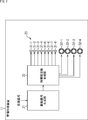
- FIG. 2 is a diagram illustrating a configuration example of an embodiment of a sound field forming device to which the present technology is applied.
- the 2 includes a drive signal generation unit 21, a time-frequency synthesis unit 22, and a global array 23.
- the driving signal generator 21 is supplied with a sound source signal that is a time domain acoustic signal (time signal) for reproducing the sound of the content.
- the drive signal generation unit 21 generates a time frequency spectrum of a speaker drive signal for reproducing sound based on the sound source signal at a desired wavefront based on the supplied sound source signal and supplies the time frequency spectrum to the time frequency synthesis unit 22.
- the time-frequency synthesis unit 22 performs time-frequency synthesis using IDFT (Inverse Discrete Fourier Transform) (Inverse Discrete Fourier Transform) on the time-frequency spectrum supplied from the drive signal generation unit 21 to drive a speaker that is a time signal. A signal is calculated and supplied to the global array 23.
- IDFT Inverse Discrete Fourier Transform
- IFT Inverse Discrete Fourier Transform
- the global array 23 forms a desired sound field (wavefront) by outputting sound based on the speaker drive signal supplied from the time-frequency synthesis unit 22.
- the global array 23 corresponds to the global array AR12 shown in FIG. 1, and includes normal speakers 31-1 to 31-8 and high-order speakers 32-1 to 32-4.
- the normal speakers 31-1 to 31-8 are also simply referred to as normal speakers 31 when it is not necessary to distinguish them.
- the high-order speakers 32-1 to 32-4 are also simply referred to as the high-order speakers 32 when it is not necessary to distinguish them.
- the normal speaker 31 corresponds to the normal speaker LSP12 shown in FIG. 1
- the high-order speaker 32 corresponds to the high-order speaker HSP12 shown in FIG.
- the global array 23 is, for example, a spherical speaker array or an annular speaker array obtained by arranging normal speakers 31 and higher-order speakers 32 in a spherical or annular shape.
- the global array 23 is not limited to the spherical speaker array or the annular speaker array, and may be any other speaker array.
- the number and arrangement positions of the normal speakers 31 and the high-order speakers 32 constituting the global array 23 and the types of the high-order speakers are determined according to the reproducibility of the wavefront in the zero-order control region and the high-order control region. .
- the drive signal generation unit 21 generates a time-frequency spectrum of the speaker drive signal supplied to each speaker unit constituting the higher-order speaker 32 or the normal speaker 31 based on the supplied sound source signal.
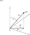
- the position of a point PO11 on a three-dimensional orthogonal coordinate system with a predetermined origin O as a reference and the x axis, the y axis, and the z axis as respective axes is expressed in polar coordinates (spherical coordinates). Think about it.
- the position of the predetermined point PO11 is expressed as polar coordinates (r, ⁇ , ⁇ ) with the origin O as a reference.
- r indicates the distance from the origin O to the point PO11
- ⁇ is the elevation angle indicating the position of the point PO11 viewed from the origin O
- ⁇ indicates the position of the point PO11 viewed from the origin O.
- a straight line connecting the origin O and the point PO11 is a straight line LN
- the length of the straight line LN is a distance r from the origin O to the point PO11.
- a straight line obtained by projecting the straight line LN from the z-axis direction onto the xy plane is a straight line LN ′
- an angle formed by the x-axis and the straight line LN ′ is an orientation indicating the position of the point PO11 viewed from the origin O
- the angle is ⁇ .
- an angle formed by the z axis and the straight line LN is an elevation angle ⁇ indicating the position of the point PO11 viewed from the origin O.
- the predetermined position is described as (r, ⁇ , ⁇ ) using polar coordinates.
- Equation (1) n and m represent orders, and N represents the maximum order. Further, ⁇ represents an angular frequency, and k represents a wave number.
- a global array obtained by arranging high-order speakers in a spherical shape is considered.
- the synthesized sound field P syn (X) by the global array at a predetermined position X viewed from the origin can be expressed by the following expression (3) using expression (2).
- l indicates a speaker index for identifying a speaker unit constituting the global array
- l 1, 2,.
- L indicates the total number of speaker units constituting the global array. Note that the speaker unit indicated by the speaker index l is a speaker unit constituting a high-order speaker of the global array.
- d 1 indicates the speaker drive signal of the speaker unit of the speaker index l, more specifically the time frequency spectrum of the speaker drive signal, and ⁇ (l) n′m ′ indicates the speaker index l.
- the coefficient showing the directivity of the speaker unit is shown.
- h n ′ (kr (l) ) and Y n′m ′ ( ⁇ (l) , ⁇ (l) ) are the positions of the speaker unit of the speaker index l as the reference (origin).
- the Hankel function and spherical harmonics expressed in polar coordinates are shown.
- the Hankel function h n ′ (kr (l) ) and the spherical harmonic function Y n′m ′ ( ⁇ (l) , ⁇ (l) ) are expressed in a polar coordinate system with the position of the speaker unit of the speaker index l as the origin.
- Hankel function and spherical harmonic function for the position X (r (l) , ⁇ (l) , ⁇ (l) ).
- n ′ and m ′ indicate the orders when the position of the speaker unit of the speaker index 1 is the origin.
- the coefficient ⁇ (l) n′m ′ is also a coefficient in the polar coordinate system with the position of the speaker unit of the speaker index l as the origin.
- the coefficient ⁇ (l) n'm ' is set to the coefficient ⁇ (O) nm, l with the center position of the global array as the origin of the polar coordinate system. Need to convert.
- Such conversion from the coefficient ⁇ (l) n′m ′ to the coefficient ⁇ (O) nm, l can be realized by using the Hankel function addition theorem. That is, by calculating the following equation (4), the coefficient ⁇ (l) n′m ′ can be converted into the coefficient ⁇ (O) nm, l .
- i represents an imaginary number
- h l (kr l ) represents a Hankel function for the speaker unit of the speaker index l
- Y * q (m ⁇ m ′) ( ⁇ l , ⁇ l ) represents the complex conjugate of the spherical harmonic function Y q (m ⁇ m ′) ( ⁇ l , ⁇ l ).
- W 1 in the equation (5) is a matrix represented by the following equation (6)
- W 2 is a matrix represented by the following equation (7).
- Equation (4) can also be applied to the conversion from the transfer function coefficient with the center position of each speaker as the origin to the transfer function coefficient with the center position of the global array as the origin.
- the transfer function g l (X) of the speaker unit of the speaker index 1 at a predetermined position X with reference to the global array is based on the above-described equations (1) and (4), and the coefficient ⁇ (O) It is expressed by the following equation (8) using nm, l , Bessel function j n (kr), and spherical harmonic function Y nm ( ⁇ , ⁇ ).
- a spherical speaker array obtained by arranging high-order speakers in a spherical shape has been described as an example of a global array composed of L speaker units.
- the global array composed of L speaker units may be a spherical speaker array obtained by arranging high-order speakers and normal speakers in a spherical shape. That is, the speaker unit of the speaker index 1 may be one speaker unit constituting a higher-order speaker, or may be a normal speaker itself.
- the coefficient ⁇ (l) n'm ' is a parameter that determines the directivity of the speaker unit.
- the coefficient ⁇ (l) n'm' has a value only for the 0th-order component.
- the global array including L speaker units is a spherical speaker array including high-order speakers and normal speakers.
- the sound field ⁇ (X) at a predetermined position X with reference to the global array has a coefficient a (O) nm , a Bessel function j n (kr), and spherical harmonics. It can be expressed by the following equation (9) using the function Y nm ( ⁇ , ⁇ ).
- the coefficient a (O) nm in equation (9) can be obtained by calculation of the following equation (10) with the polar coordinates of the sound source position as (r s , ⁇ s , ⁇ s ) using an analytical solution of spherical waves. it can.
- i represents an imaginary number
- k represents a wave number
- h (2) n (kr s ) represents a second-type ball Hankel function.
- Y * nm ( ⁇ s , ⁇ s ) indicates the complex conjugate of the spherical harmonic function Y nm ( ⁇ s , ⁇ s ).
- g (X) represents a matrix (row vector) composed of the transfer functions g l (X) of the speaker units of L speaker indexes l.
- (psi) in Formula (12) and Formula (13) is a matrix (row vector) represented by the following formula
- C H represents a Hermitian transposed matrix of a matrix C having a coefficient ⁇ (O) nm, l , represented by the following Expression (15).
- a H represents a Hermitian transposed matrix of a matrix (row vector) a composed of a coefficient a (O) nm , represented by the following Expression (16).
- the matrix D in the equation (17) is a matrix composed of the time frequency spectrum d l of the speaker drive signal of the speaker unit of each speaker index l as shown in the following equation (18).
- Equation (19) W is a matrix shown in the following Equation (20), and w nm that is an element of the matrix W is shown by the following Equation (21).
- ⁇ nm represents the Kronecker delta
- W shown in equation (20) is a diagonal matrix
- the drive signal generation unit 21 calculates the equation (19) using the coefficient a (O) nm represented by the above-described equation (11), which is obtained based on the supplied sound source signal S, so that the global array 23 Is obtained and supplied to the time-frequency synthesis unit 22.
- the speaker unit of the speaker index l corresponds to the speaker unit that constitutes the global speaker 23 and that constitutes the normal speaker 31 itself and the higher-order speaker 32.
- the time-frequency synthesis unit 22 performs a time-frequency synthesis by IDFT for the time frequency spectrum d l of the speaker drive signal supplied from the drive signal generation unit 21, a speaker driving of the speaker unit of the speaker index l, which is a time signal Find the signal.
- the time frequency index is n tf
- the time frequency spectrum d l of the speaker unit of the speaker index l is described as the time frequency spectrum D (l, n tf ).
- the time-frequency synthesizer 22 calculates the following equation (22) to obtain the speaker drive signal d (l, nt ) of the speaker unit with the speaker index l.
- n t represents a time index
- M dt represents the number of IDFT samples
- i represents an imaginary number
- the time-frequency synthesis unit 22 the thus obtained speaker drive signal d (l, n t), supplied to the speaker units constituting the global array 23 to output the sound.
- step S ⁇ b> 11 the drive signal generation unit 21 generates a time frequency spectrum of the speaker drive signal of each speaker unit constituting the global array 23 based on the supplied sound source signal and supplies the time frequency spectrum to the time frequency synthesis unit 22.
- the drive signal generation unit 21 calculates the equation (19) using the coefficient a (O) nm obtained by the equation (11) based on the sound source signal, so that each speaker unit constituting the global array 23 is calculated. Generate a time-frequency spectrum.
- step S ⁇ b> 12 the time-frequency synthesis unit 22 performs time-frequency synthesis on the time-frequency spectrum of the speaker drive signal supplied from the drive signal generation unit 21, and the speaker drive signal of each speaker unit constituting the global array 23. Is generated.
- the time-frequency synthesis unit 22 generates a speaker drive signal for each speaker unit by calculating Expression (22), and supplies it to the global array 23.
- step S13 the global array 23 outputs a sound based on the speaker drive signal supplied from the time frequency synthesis unit 22. Thereby, a desired sound field, that is, a desired wavefront is formed, and a sound based on the sound source signal is reproduced.
- the sound field forming device 11 generates the speaker drive signal based on the sound source signal, and reproduces the sound based on the sound source signal by the global array 23.
- the global array 23 a sufficient sound field reproducibility can be obtained even at a low cost by using the normal speaker 31 and the higher order speaker 32 in combination.
- a method of generating a speaker drive signal directly by calculation based on a supplied sound source signal, like the sound field forming device 11, is particularly useful when a sound source signal is predetermined.
- the sound source signal is determined in advance, if the speaker driving signal is generated in advance, the sound of the content or the like can be reproduced immediately when necessary.
- a filter coefficient for forming a desired wavefront may be generated in advance, and the speaker drive signal may be generated by convolution processing of the filter coefficient and the sound source signal.
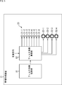
- the sound field forming device is configured, for example, as shown in FIG.
- parts corresponding to those in FIG. 1 are denoted by the same reference numerals, and description thereof will be omitted as appropriate.
- the sound field forming device 71 shown in FIG. 1 has a filter coefficient recording unit 81, a filter coefficient superimposing unit 82, and a global array 23.
- the filter coefficient recording unit 81 records a filter coefficient for reproducing (forming) a predetermined wavefront generated in advance, and supplies the recorded filter coefficient to the filter coefficient superimposing unit 82.
- the filter coefficient superimposing unit 82 convolves the supplied sound source signal with the filter coefficient supplied from the filter coefficient recording unit 81 to generate a speaker drive signal for each speaker unit constituting the global array 23, and 23.
- the speaker drive signal of each speaker unit is generated by the filter processing based on the filter coefficient and the sound source signal.
- the sound field forming device 71 can quickly obtain a speaker drive signal by filtering, the sound field forming device 71 is particularly useful when the sound source signal changes frequently.
- the filter coefficient recording unit 81 records a filter coefficient of an audio filter for reproducing a predetermined wavefront by combining a plurality of normal speakers 31 and higher-order speakers 32, that is, for forming a desired sound field.
- the filter coefficient of the time index n t for the speaker unit of the speaker index l is denoted as h (l, n t ).
- the speaker drive signal d (l, nt ) obtained by calculating Expression (19) and Expression (22) using the coefficient a (O) nm shown in Expression (10) is the filter coefficient h. Used as (l, n t ).
- Filter coefficient recording unit 81 previously generated filter coefficients h (l, n t) are recorded, and supplies the filter coefficients h (l, n t) to the filter coefficient superposed section 82.
- the filter coefficient superimposing unit 82 convolves the filter coefficient h (l, n t ) supplied from the filter coefficient recording unit 81 with the supplied sound source signal, and the speaker drive signal d (l, n t ) of each speaker unit. )
- the filter coefficient superimposing unit 82 supplies the obtained speaker drive signal to each speaker unit constituting the global array 23 and outputs sound.
- the filter coefficient superimposing unit 82 calculates the following equation (23) to obtain the filter coefficient h (l, n t ), the sound source signal x (n t ), and And the speaker drive signal d (l, nt ) is calculated.
- N indicates the filter length of the audio filter composed of the filter coefficient h (l, nt ).
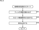
- step S ⁇ b > 51 the filter coefficient superimposing unit 82 reads out the filter coefficient h (l, nt ) from the filter coefficient recording unit 81.
- step S52 the filter coefficient superposed section 82, the filter coefficients h (l, n t) read out in the processing of step S51 and, speaker drive signal d (l, based on the supplied source signal x (n t), n t ) is generated and supplied to the global array 23.
- step S52 the calculation of the above-described equation (23) is performed, and the speaker drive signal d (l, nt ) of each speaker unit constituting the global array 23 is generated.
- step S ⁇ b> 53 the global array 23 outputs sound based on the speaker drive signal d (l, nt ) supplied from the filter coefficient superimposing unit 82. Thereby, a desired sound field, that is, a desired wavefront is formed, and a sound based on the sound source signal is reproduced.
- the sound field forming device 71 generates the speaker drive signal based on the sound source signal, and reproduces the sound based on the sound source signal by the global array 23.
- the sound field forming device 71 as in the case of the sound field forming device 11, by using the normal speaker 31 and the higher order speaker 32 in combination, sufficient sound field reproducibility can be obtained even at a low cost.
- the arrangement of normal speakers and higher-order speakers may be a three-dimensional arrangement such as a spherical arrangement or a two-dimensional arrangement such as an annular arrangement.
- Ordinary speakers and higher-order speakers may be arranged at equal density (equal intervals), or may be arranged at unequal densities (unequal intervals).
- the global array 111 to which the present technology is applied includes normal speakers 121-1 to 121-6 and higher-order speakers 122-1 to 122-3.
- This global array 111 corresponds to the global array 23 of FIG.
- normal speakers 121-1 to 121-6 when it is not necessary to particularly distinguish the normal speakers 121-1 to 121-6, they are also simply referred to as normal speakers 121, and it is necessary to particularly distinguish the high-order speakers 122-1 to 122-3. If not, it is also simply referred to as a higher order speaker 122.
- six normal speakers 121 and three higher-order speakers 122 are annularly arranged at unequal density to form a global array 111.
- more normal speakers 121 and higher-order speakers 122 are arranged in the right part of the diagram in the global array 111, compared to the left part in the diagram of the global array 111.
- the density is high.
- all the high-order speakers 122 are arranged in the right portion of the global array 111 in the drawing.
- the reproducibility of the wavefront propagating from the direction of high speaker density toward the center position of the global array 111 is enhanced.
- the reproducibility of the wavefront propagating from the direction of low speaker density toward the center position of the global array 111 is low.
- the speaker density is high on the right side of the global array 111.
- the wavefront propagating from the right side to the center position of the global array 111 in the diagram of the global array 111 can be reproduced with higher accuracy.
- the sound source AS ⁇ b> 11 is located on the side where the number of normal speakers 121 and higher-order speakers 122 is large in the region outside the global array 111, that is, on the upper right side in the diagram of the global array 111. Then, the wavefront of the sound emitted from the sound source AS11 propagates from the sound source AS11 toward the center of the global array 111.
- the wavefront of the sound from the sound source AS11 can be reproduced with high accuracy in the region inside the global array 111.
- the wavefront propagating from the lower right to the center position of the global array 111 in the diagram of the global array 111 can be reproduced with high accuracy, for example, as indicated by an arrow Q11.
- the arrival direction of the wavefront of the sound is limited depending on the content to be played back, for example, if the speaker arrangement of the global array 111 is determined so as to increase the speaker density on the direction in which the wavefront arrives Good. In this way, not only can the wavefront of the content sound be formed with high reproducibility, but also the number of speakers in the global array 111 can be reduced.
- the arrangement of normal speakers and higher-order speakers constituting the global array is determined according to the shape of the control area, which is the area where the sound field (wavefront) is to be reproduced by the global array, it is efficient at low cost. It is possible to form a sound field.
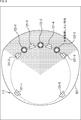
- FIG. 8 When the direction (region) in which the sound field outside the global array is desired to be reproduced is limited, for example, a speaker arrangement as shown in FIG. 8, portions corresponding to those in FIG. 7 are denoted by the same reference numerals, and description thereof will be omitted as appropriate.
- a region R21 including the outside and inside of the global array 111 is a control region (hereinafter also referred to as a control region R21) in which the global array 111 is desired to reproduce a sound field.
- the left region in the diagram of the global array 111 is not the control region R21, so the high-order speaker 122 is arranged on the left side in the diagram of the global array 111.
- the speaker density is low.
- the region on the right side in the diagram of the global array 111 is included in the control region R21.
- Many 122 are arrange
- the high-order speakers 122 are arranged at a high density in the vicinity of the region where the sound field is desired to be reproduced, and the sound field need not be reproduced. In the vicinity of such a region, the speaker density may be lowered.
- the sound field (wavefront) can be reproduced efficiently and sufficiently accurately with a small number of speakers inside and outside the global array 111.
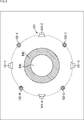
- control area is an area inside the global array.
- the global array 151 includes normal speakers 161-1 to 161-4 and high-order speakers 162-1 to 162-4. This global array 151 corresponds to the global array 23 of FIG.
- normal speaker 161 when it is not necessary to distinguish between the normal speakers 161-1 to 161-4, it is also simply referred to as a normal speaker 161 and it is necessary to particularly distinguish the higher-order speakers 162-1 to 162-4. If not, it is also simply referred to as a higher order speaker 162.
- four normal speakers 161 and four higher-order speakers 162 are annularly arranged with equal density (equal spacing).
- a circular region inside the global array 151 is a control region. That is, the sound field (wavefront) cannot be formed with sufficient reproducibility in the region outside the global array 151.
- a control region of the global array 151 is a region composed of a circular region R41 including the center position of the global array 151 and an annular (ring-shaped) region R42 surrounding the region R41.
- the region R41 is a zero-order control region in which a sound field is mainly formed by the normal speaker 161
- the region R42 is a high-order control region in which a sound field is mainly formed by the high-order speaker 162.
- ⁇ Application example 2 of this technology> ⁇ Combination of high-order speakers> Further, in the above description, an example in which the same type of high-order speakers constituting the global array is used has been described. However, a global array may be configured by combining a plurality of different types of high-order speakers. .
- the types of higher-order speakers are different, for example, the number and size of speaker units constituting the higher-order speakers, the shape of the speaker array as a higher-order speaker such as an annular shape or a spherical shape, and the orientation that can be reproduced by the higher-order speakers. This means that the number of sexes (orders) is different.
- a global array to which the present technology is applied is configured as shown in FIG.
- the global array 191 shown in FIG. 10 includes normal speakers 201-1 through 201-8, higher-order speakers 202-1 through 202-3, and higher-order speakers 203-1 through 203-5. It consists of. This global array 191 corresponds to the global array 23 of FIG.
- the normal speakers 201-1 to 201-8 are also simply referred to as the normal speakers 201, and it is necessary to particularly distinguish the high-order speakers 202-1 to 202-3. If not, it is also simply referred to as a higher order speaker 202.
- the high-order speaker 203-1 to the high-order speaker 203-5 are also simply referred to as a high-order speaker 203 when it is not necessary to distinguish them.
- eight normal speakers 201, three high-order speakers 202, and five high-order speakers 203 are annularly arranged at unequal density (equal intervals).
- the high-order speaker 202 and the high-order speaker 203 are different types of high-order speakers. That is, for example, the high-order speaker 202 is composed of a larger number of speaker units than the high-order speaker 203 and is a high-order speaker that can reproduce even higher directivity than the high-order speaker 203. is there.
- the arrangement position of the normal speakers 201, the high-order speakers 202, and the high-order speakers 203, the number of loudspeakers, the type of high-order speakers, etc. are appropriately determined according to the control area of the global array 191, low cost and sufficient efficiency Sound field can be formed with excellent reproducibility.
- the arrangement of the normal speaker 201, the high-order speaker 202, and the high-order speaker 203 according to the reproducibility of the sound field (wavefront) required in the zero-order control region that can be controlled by the normal speaker 201 in the control region. If the position and the number of arrangements are determined, a sound field can be formed efficiently and with sufficiently high reproducibility in the zero-order control region.
- the arrangement position, the number of arrangements, and the types of the higher-order speakers 202 and 203 are determined. For example, a sound field can be efficiently and sufficiently reproducibly formed in a high-order control region.
- the above-described series of processing can be executed by hardware or can be executed by software.
- a program constituting the software is installed in the computer.
- the computer includes, for example, a general-purpose computer capable of executing various functions by installing a computer incorporated in dedicated hardware and various programs.
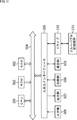
- FIG. 11 is a block diagram showing an example of a hardware configuration of a computer that executes the above-described series of processing by a program.
- a CPU Central Processing Unit
- ROM Read Only Memory
- RAM Random Access Memory
- An input / output interface 505 is further connected to the bus 504.
- An input unit 506, an output unit 507, a recording unit 508, a communication unit 509, and a drive 510 are connected to the input / output interface 505.
- the input unit 506 includes a keyboard, a mouse, a microphone array, an image sensor, and the like.
- the output unit 507 includes a display, a speaker array, and the like.
- the recording unit 508 includes a hard disk, a nonvolatile memory, and the like.
- the communication unit 509 includes a network interface or the like.
- the drive 510 drives a removable recording medium 511 such as a magnetic disk, an optical disk, a magneto-optical disk, or a semiconductor memory.
- the CPU 501 loads the program recorded in the recording unit 508 to the RAM 503 via the input / output interface 505 and the bus 504 and executes the program, for example. Is performed.
- the program executed by the computer (CPU 501) can be provided by being recorded in a removable recording medium 511 as a package medium or the like, for example.
- the program can be provided via a wired or wireless transmission medium such as a local area network, the Internet, or digital satellite broadcasting.
- the program can be installed in the recording unit 508 via the input / output interface 505 by attaching the removable recording medium 511 to the drive 510. Further, the program can be received by the communication unit 509 via a wired or wireless transmission medium and installed in the recording unit 508. In addition, the program can be installed in advance in the ROM 502 or the recording unit 508.
- the program executed by the computer may be a program that is processed in time series in the order described in this specification, or in parallel or at a necessary timing such as when a call is made. It may be a program for processing.
- the present technology can take a cloud computing configuration in which one function is shared by a plurality of devices via a network and is jointly processed.
- each step described in the above flowchart can be executed by one device or can be shared by a plurality of devices.
- the plurality of processes included in the one step can be executed by being shared by a plurality of apparatuses in addition to being executed by one apparatus.
- the present technology can be configured as follows.
- Consists of a plurality of higher-order speakers and a plurality of normal speakers A speaker array in which the type, number, or arrangement position of the higher-order speakers is determined according to the reproducibility of the wavefront in a second region outside the first region that can be controlled by the normal speaker.
- the speaker array according to (1) wherein the number or arrangement position of the high-order speakers and the normal speakers is determined according to the reproducibility of the wavefront in the first region.
- the speaker array according to (1) or (2), wherein the plurality of higher-order speakers and the plurality of normal speakers are arranged at unequal density.
- the signal processing device according to any one of (8) to (10), wherein the plurality of higher-order speakers include different types of higher-order speakers. (12) The signal processing apparatus according to (11), wherein the different types of higher-order speakers are the higher-order speakers having different reproducible directivities. (13) The signal processing device according to any one of (8) to (12), wherein the high-order speaker is a speaker capable of reproducing a plurality of directivities. (14) The signal processing apparatus according to any one of (8) to (13), wherein the normal speaker is a speaker that can reproduce only a single directivity.
- 11 sound field forming device 21 drive signal generator, 22 time frequency synthesizer, 23 global array, 31-1 to 31-8, 31 normal speaker, 32-1 to 32-4, 32 higher order speaker, 81 filter coefficient Recording part, 82 Filter coefficient superposition part
Landscapes
- Health & Medical Sciences (AREA)
- Otolaryngology (AREA)
- Physics & Mathematics (AREA)
- Engineering & Computer Science (AREA)
- Acoustics & Sound (AREA)
- Signal Processing (AREA)
- General Health & Medical Sciences (AREA)
- Circuit For Audible Band Transducer (AREA)
- Obtaining Desirable Characteristics In Audible-Bandwidth Transducers (AREA)
- Stereophonic System (AREA)
Abstract
Description
〈本技術について〉
本技術は、高次スピーカと通常スピーカとを組み合わせてスピーカアレイを構成することで、低コストでも十分な音場再現性を得ることができるようにするものである。
それでは、以下、本技術を適用したより具体的な実施の形態について説明する。
続いて、音場形成装置11を構成する各部についてより詳細に説明する。





















時間周波数合成部22は、駆動信号生成部21から供給されたスピーカ駆動信号の時間周波数スペクトルdlに対してIDFTにより時間周波数合成を行い、時間信号である各スピーカインデクスlのスピーカユニットのスピーカ駆動信号を求める。

続いて、音場形成装置11の動作について説明する。すなわち、以下、図4のフローチャートを参照して、音場形成装置11により行われる音場形成処理について説明する。
〈音場形成装置の構成例〉
なお、スピーカ駆動信号を生成する場合に、予め所望の波面を形成するためのフィルタ係数を生成しておき、フィルタ係数と音源信号との畳み込み処理によりスピーカ駆動信号を生成するようにしてもよい。
ここで、音場形成装置71の各部についてさらに詳細に説明する。
フィルタ係数重畳部82は、フィルタ係数記録部81から供給されたフィルタ係数h(l,nt)と、供給された音源信号とを畳み込んで各スピーカユニットのスピーカ駆動信号d(l,nt)を求める。フィルタ係数重畳部82は、得られたスピーカ駆動信号をグローバルアレイ23を構成する各スピーカユニットに供給し、音を出力させる。

続いて、音場形成装置71の動作について説明する。すなわち、以下、図6のフローチャートを参照して、音場形成装置71により行われる音場形成処理について説明する。
〈スピーカの不等密度配置について〉
ところで、本技術を適用したグローバルアレイでは、通常スピーカや高次スピーカの配置を球状配置などの3次元的な配置としてもよいし、環状配置などの2次元的な配置としてもよい。
〈高次スピーカの組み合わせについて〉
さらに、以上においては、グローバルアレイを構成する高次スピーカは全て同じ種類のものが用いられる例について説明したが、互いに異なる複数種類の高次スピーカを組み合わせてグローバルアレイを構成するようにしてもよい。
ところで、上述した一連の処理は、ハードウェアにより実行することもできるし、ソフトウェアにより実行することもできる。一連の処理をソフトウェアにより実行する場合には、そのソフトウェアを構成するプログラムが、コンピュータにインストールされる。ここで、コンピュータには、専用のハードウェアに組み込まれているコンピュータや、各種のプログラムをインストールすることで、各種の機能を実行することが可能な、例えば汎用のコンピュータなどが含まれる。
複数の高次スピーカと、複数の通常スピーカとから構成され、
前記通常スピーカにより制御可能な第1の領域の外側にある第2の領域における波面の再現性に応じて前記高次スピーカの種類、数、または配置位置が定められた
スピーカアレイ。
(2)
前記第1の領域における波面の再現性に応じて、前記高次スピーカおよび前記通常スピーカの数または配置位置が定められている
(1)に記載のスピーカアレイ。
(3)
前記複数の前記高次スピーカおよび前記複数の前記通常スピーカが不等密度で配置されている
(1)または(2)に記載のスピーカアレイ。
(4)
前記複数の前記高次スピーカのなかには、互いに異なる種類の前記高次スピーカが含まれている
(1)乃至(3)の何れか一項に記載のスピーカアレイ。
(5)
互いに異なる種類の前記高次スピーカは、再現可能な指向性が異なる前記高次スピーカである
(4)に記載のスピーカアレイ。
(6)
前記高次スピーカは、複数の指向性を再現可能なスピーカである
(1)乃至(5)の何れか一項に記載のスピーカアレイ。
(7)
前記通常スピーカは、単一の指向性のみ再現可能なスピーカである
(1)乃至(6)の何れか一項に記載のスピーカアレイ。
(8)
複数の高次スピーカと、複数の通常スピーカとから構成され、前記通常スピーカにより制御可能な第1の領域の外側にある第2の領域における波面の再現性に応じて前記高次スピーカの種類、数、または配置位置が定められたスピーカアレイと、
音源信号に基づいて、前記スピーカアレイの駆動信号を生成する駆動信号生成部と
を備える信号処理装置。
(9)
前記第1の領域における波面の再現性に応じて、前記高次スピーカおよび前記通常スピーカの数または配置位置が定められている
(8)に記載の信号処理装置。
(10)
前記複数の前記高次スピーカおよび前記複数の前記通常スピーカが不等密度で配置されている
(8)または(9)に記載の信号処理装置。
(11)
前記複数の前記高次スピーカのなかには、互いに異なる種類の前記高次スピーカが含まれている
(8)乃至(10)の何れか一項に記載の信号処理装置。
(12)
互いに異なる種類の前記高次スピーカは、再現可能な指向性が異なる前記高次スピーカである
(11)に記載の信号処理装置。
(13)
前記高次スピーカは、複数の指向性を再現可能なスピーカである
(8)乃至(12)の何れか一項に記載の信号処理装置。
(14)
前記通常スピーカは、単一の指向性のみ再現可能なスピーカである
(8)乃至(13)の何れか一項に記載の信号処理装置。
Claims (14)
- 複数の高次スピーカと、複数の通常スピーカとから構成され、
前記通常スピーカにより制御可能な第1の領域の外側にある第2の領域における波面の再現性に応じて前記高次スピーカの種類、数、または配置位置が定められた
スピーカアレイ。 - 前記第1の領域における波面の再現性に応じて、前記高次スピーカおよび前記通常スピーカの数または配置位置が定められている
請求項1に記載のスピーカアレイ。 - 前記複数の前記高次スピーカおよび前記複数の前記通常スピーカが不等密度で配置されている
請求項1に記載のスピーカアレイ。 - 前記複数の前記高次スピーカのなかには、互いに異なる種類の前記高次スピーカが含まれている
請求項1に記載のスピーカアレイ。 - 互いに異なる種類の前記高次スピーカは、再現可能な指向性が異なる前記高次スピーカである
請求項4に記載のスピーカアレイ。 - 前記高次スピーカは、複数の指向性を再現可能なスピーカである
請求項1に記載のスピーカアレイ。 - 前記通常スピーカは、単一の指向性のみ再現可能なスピーカである
請求項1に記載のスピーカアレイ。 - 複数の高次スピーカと、複数の通常スピーカとから構成され、前記通常スピーカにより制御可能な第1の領域の外側にある第2の領域における波面の再現性に応じて前記高次スピーカの種類、数、または配置位置が定められたスピーカアレイと、
音源信号に基づいて、前記スピーカアレイの駆動信号を生成する駆動信号生成部と
を備える信号処理装置。 - 前記第1の領域における波面の再現性に応じて、前記高次スピーカおよび前記通常スピーカの数または配置位置が定められている
請求項8に記載の信号処理装置。 - 前記複数の前記高次スピーカおよび前記複数の前記通常スピーカが不等密度で配置されている
請求項8に記載の信号処理装置。 - 前記複数の前記高次スピーカのなかには、互いに異なる種類の前記高次スピーカが含まれている
請求項8に記載の信号処理装置。 - 互いに異なる種類の前記高次スピーカは、再現可能な指向性が異なる前記高次スピーカである
請求項11に記載の信号処理装置。 - 前記高次スピーカは、複数の指向性を再現可能なスピーカである
請求項8に記載の信号処理装置。 - 前記通常スピーカは、単一の指向性のみ再現可能なスピーカである
請求項8に記載の信号処理装置。
Priority Applications (4)
| Application Number | Priority Date | Filing Date | Title |
|---|---|---|---|
| CN201880030916.8A CN110637466B (zh) | 2017-05-16 | 2018-05-02 | 扬声器阵列与信号处理装置 |
| EP18802522.5A EP3627850A4 (en) | 2017-05-16 | 2018-05-02 | SPEAKER ARRAY AND SIGNAL PROCESSOR |
| JP2019519173A JP7099456B2 (ja) | 2017-05-16 | 2018-05-02 | スピーカアレイ、および信号処理装置 |
| US16/611,582 US11076230B2 (en) | 2017-05-16 | 2018-05-02 | Speaker array, and signal processing apparatus |
Applications Claiming Priority (2)
| Application Number | Priority Date | Filing Date | Title |
|---|---|---|---|
| JP2017097421 | 2017-05-16 | ||
| JP2017-097421 | 2017-05-16 |
Publications (1)
| Publication Number | Publication Date |
|---|---|
| WO2018211984A1 true WO2018211984A1 (ja) | 2018-11-22 |
Family
ID=64274309
Family Applications (1)
| Application Number | Title | Priority Date | Filing Date |
|---|---|---|---|
| PCT/JP2018/017485 Ceased WO2018211984A1 (ja) | 2017-05-16 | 2018-05-02 | スピーカアレイ、および信号処理装置 |
Country Status (5)
| Country | Link |
|---|---|
| US (1) | US11076230B2 (ja) |
| EP (1) | EP3627850A4 (ja) |
| JP (1) | JP7099456B2 (ja) |
| CN (1) | CN110637466B (ja) |
| WO (1) | WO2018211984A1 (ja) |
Cited By (2)
| Publication number | Priority date | Publication date | Assignee | Title |
|---|---|---|---|---|
| JP2023507021A (ja) * | 2019-12-20 | 2023-02-20 | ホアウェイ・テクノロジーズ・カンパニー・リミテッド | 三次元音場を生成するためのオーディオデバイスおよび方法 |
| JP2023121021A (ja) * | 2022-02-18 | 2023-08-30 | 日本放送協会 | 音場再現装置及びプログラム |
Citations (2)
| Publication number | Priority date | Publication date | Assignee | Title |
|---|---|---|---|---|
| JP2016144129A (ja) * | 2015-02-04 | 2016-08-08 | 日本電信電話株式会社 | 音場再生装置、音場再生方法、プログラム |
| JP2017034442A (ja) * | 2015-07-31 | 2017-02-09 | 日本電信電話株式会社 | 音場再生装置およびその方法 |
Family Cites Families (17)
| Publication number | Priority date | Publication date | Assignee | Title |
|---|---|---|---|---|
| US7826622B2 (en) * | 2003-05-27 | 2010-11-02 | Harman International Industries, Incorporated | Constant-beamwidth loudspeaker array |
| JP2006115396A (ja) * | 2004-10-18 | 2006-04-27 | Sony Corp | オーディオ信号の再生方法およびその再生装置 |
| KR101298487B1 (ko) * | 2008-12-10 | 2013-08-22 | 삼성전자주식회사 | 지향성 음향 발생장치 및 방법 |
| US8189822B2 (en) * | 2009-06-18 | 2012-05-29 | Robert Bosch Gmbh | Modular, line-array loudspeaker |
| US8917881B2 (en) * | 2010-01-26 | 2014-12-23 | Cheng Yih Jenq | Enclosure-less loudspeaker system |
| EP2450880A1 (en) | 2010-11-05 | 2012-05-09 | Thomson Licensing | Data structure for Higher Order Ambisonics audio data |
| US9549277B2 (en) * | 2011-05-11 | 2017-01-17 | Sonicemotion Ag | Method for efficient sound field control of a compact loudspeaker array |
| JP5985063B2 (ja) * | 2012-08-31 | 2016-09-06 | ドルビー ラボラトリーズ ライセンシング コーポレイション | レンダラーと個々に指定可能なドライバのアレイとの間の通信のための双方向相互接続 |
| DK2863654T3 (en) * | 2013-10-17 | 2018-10-22 | Oticon As | Method for reproducing an acoustic sound field |
| JP6458738B2 (ja) * | 2013-11-19 | 2019-01-30 | ソニー株式会社 | 音場再現装置および方法、並びにプログラム |
| GB201321325D0 (en) * | 2013-12-03 | 2014-01-15 | Ecole Polytechnique F D Rale De Lausanne | A sound diffusion system for directional sound enhancement |
| US9596544B1 (en) * | 2015-12-30 | 2017-03-14 | Gregory Douglas Brotherton | Head mounted phased focused speakers |
| JP6905824B2 (ja) * | 2016-01-04 | 2021-07-21 | ハーマン ベッカー オートモーティブ システムズ ゲーエムベーハー | 非常に多数のリスナのための音響再生 |
| US10412531B2 (en) * | 2016-01-08 | 2019-09-10 | Sony Corporation | Audio processing apparatus, method, and program |
| WO2018008396A1 (ja) * | 2016-07-05 | 2018-01-11 | ソニー株式会社 | 音場形成装置および方法、並びにプログラム |
| CN206061115U (zh) * | 2016-08-23 | 2017-03-29 | 费迪曼逊多媒体科技(上海)有限公司 | 一种在环形听音空间内应用wfs波场合成的扬声器布局结构 |
| EP3467819B1 (en) * | 2017-10-05 | 2024-06-12 | Harman Becker Automotive Systems GmbH | Apparatus and method using multiple voice command devices |
-
2018
- 2018-05-02 JP JP2019519173A patent/JP7099456B2/ja active Active
- 2018-05-02 EP EP18802522.5A patent/EP3627850A4/en not_active Withdrawn
- 2018-05-02 US US16/611,582 patent/US11076230B2/en active Active
- 2018-05-02 WO PCT/JP2018/017485 patent/WO2018211984A1/ja not_active Ceased
- 2018-05-02 CN CN201880030916.8A patent/CN110637466B/zh active Active
Patent Citations (2)
| Publication number | Priority date | Publication date | Assignee | Title |
|---|---|---|---|---|
| JP2016144129A (ja) * | 2015-02-04 | 2016-08-08 | 日本電信電話株式会社 | 音場再生装置、音場再生方法、プログラム |
| JP2017034442A (ja) * | 2015-07-31 | 2017-02-09 | 日本電信電話株式会社 | 音場再生装置およびその方法 |
Non-Patent Citations (4)
| Title |
|---|
| P. A. MARTIN: "Multiple scattering: interaction of time-harmonic waves with N obstacles", 2006, CAMBRIDGE UNIV PR |
| SAMARASINGHE, PRASANGA N. ET AL.: "2013 IEEE International Conference on Acoustics, Speech and Signal Processing", 2013, IEEE, article "3D sound field reproduction using higher order loudspeakers" |
| See also references of EP3627850A4 |
| UENO ET AL.: "Sound Field Reproduction Using Prior Information about Reception Area: Verification with Linear Array", REPORTS OF THE AUTUMN MEETING OF ACOUSTICAL SOCIETY OF JAPAN, 2016, pages 415 - 418 |
Cited By (5)
| Publication number | Priority date | Publication date | Assignee | Title |
|---|---|---|---|---|
| JP2023507021A (ja) * | 2019-12-20 | 2023-02-20 | ホアウェイ・テクノロジーズ・カンパニー・リミテッド | 三次元音場を生成するためのオーディオデバイスおよび方法 |
| JP7436673B2 (ja) | 2019-12-20 | 2024-02-21 | ホアウェイ・テクノロジーズ・カンパニー・リミテッド | 三次元音場を生成するためのオーディオデバイスおよび方法 |
| US12348950B2 (en) | 2019-12-20 | 2025-07-01 | Huawei Technologies Co., Ltd. | Audio device and method for generating a three-dimensional soundfield |
| JP2023121021A (ja) * | 2022-02-18 | 2023-08-30 | 日本放送協会 | 音場再現装置及びプログラム |
| JP7792263B2 (ja) | 2022-02-18 | 2025-12-25 | 日本放送協会 | 音場再現装置及びプログラム |
Also Published As
| Publication number | Publication date |
|---|---|
| JPWO2018211984A1 (ja) | 2020-03-19 |
| CN110637466B (zh) | 2021-08-06 |
| EP3627850A4 (en) | 2020-05-06 |
| CN110637466A (zh) | 2019-12-31 |
| JP7099456B2 (ja) | 2022-07-12 |
| EP3627850A1 (en) | 2020-03-25 |
| US11076230B2 (en) | 2021-07-27 |
| US20210084412A1 (en) | 2021-03-18 |
Similar Documents
| Publication | Publication Date | Title |
|---|---|---|
| US10382849B2 (en) | Spatial audio processing apparatus | |
| US6444892B1 (en) | Sound system and method for creating a sound event based on a modeled sound field | |
| CN103650540B (zh) | 紧凑扬声器阵列的高效声场控制的方法 | |
| WO2018008395A1 (ja) | 音場形成装置および方法、並びにプログラム | |
| JP5024792B2 (ja) | 全方位周波数指向性音響装置 | |
| CN106105261B (zh) | 声场声音拾取装置和方法、声场再现装置和方法以及程序 | |
| JP2019047478A (ja) | 音響信号処理装置、音響信号処理方法および音響信号処理プログラム | |
| US10321234B2 (en) | Signal processing device and signal processing method | |
| Zotkin et al. | Incident field recovery for an arbitrary-shaped scatterer | |
| JP2019050492A (ja) | フィルタ係数決定装置、フィルタ係数決定方法、プログラム、および音響システム | |
| JP6955186B2 (ja) | 音響信号処理装置、音響信号処理方法および音響信号処理プログラム | |
| JP7099456B2 (ja) | スピーカアレイ、および信号処理装置 | |
| JP5010148B2 (ja) | 3次元パンニング装置 | |
| Ahrens et al. | Rendering of virtual sound sources with arbitrary directivity in higher order ambisonics | |
| JP6970366B2 (ja) | 音像再現装置、音像再現方法及び音像再現プログラム | |
| JP6345634B2 (ja) | 音場再生装置およびその方法 | |
| Morgenstern | Joint design of spherical microphone and loudspeaker arrays for room acoustic analysis | |
| Zea | Binaural In-Ear Monitoring of acoustic instruments in live music performance | |
| Bai et al. | Sound field reproduction based on the Basis Function Method and Equivalent Source Method | |
| JP2021027536A (ja) | スピーカアレイ、信号処理装置、信号処理方法および信号処理プログラム |
Legal Events
| Date | Code | Title | Description |
|---|---|---|---|
| 121 | Ep: the epo has been informed by wipo that ep was designated in this application |
Ref document number: 18802522 Country of ref document: EP Kind code of ref document: A1 |
|
| ENP | Entry into the national phase |
Ref document number: 2019519173 Country of ref document: JP Kind code of ref document: A |
|
| NENP | Non-entry into the national phase |
Ref country code: DE |
|
| ENP | Entry into the national phase |
Ref document number: 2018802522 Country of ref document: EP Effective date: 20191216 |
|
| WWW | Wipo information: withdrawn in national office |
Ref document number: 2018802522 Country of ref document: EP |