WO2018212153A1 - 光測定装置、カテーテルキット及び光測定方法 - Google Patents
光測定装置、カテーテルキット及び光測定方法 Download PDFInfo
- Publication number
- WO2018212153A1 WO2018212153A1 PCT/JP2018/018680 JP2018018680W WO2018212153A1 WO 2018212153 A1 WO2018212153 A1 WO 2018212153A1 JP 2018018680 W JP2018018680 W JP 2018018680W WO 2018212153 A1 WO2018212153 A1 WO 2018212153A1
- Authority
- WO
- WIPO (PCT)
- Prior art keywords
- catheter
- hoop
- tip
- light
- distal end
- Prior art date
- Legal status (The legal status is an assumption and is not a legal conclusion. Google has not performed a legal analysis and makes no representation as to the accuracy of the status listed.)
- Ceased
Links
Images


Classifications
-
- A—HUMAN NECESSITIES
- A61—MEDICAL OR VETERINARY SCIENCE; HYGIENE
- A61B—DIAGNOSIS; SURGERY; IDENTIFICATION
- A61B18/00—Surgical instruments, devices or methods for transferring non-mechanical forms of energy to or from the body
- A61B18/18—Surgical instruments, devices or methods for transferring non-mechanical forms of energy to or from the body by applying electromagnetic radiation, e.g. microwaves
- A61B18/20—Surgical instruments, devices or methods for transferring non-mechanical forms of energy to or from the body by applying electromagnetic radiation, e.g. microwaves using laser
- A61B18/22—Surgical instruments, devices or methods for transferring non-mechanical forms of energy to or from the body by applying electromagnetic radiation, e.g. microwaves using laser the beam being directed along or through a flexible conduit, e.g. an optical fibre; Couplings or hand-pieces therefor
- A61B18/24—Surgical instruments, devices or methods for transferring non-mechanical forms of energy to or from the body by applying electromagnetic radiation, e.g. microwaves using laser the beam being directed along or through a flexible conduit, e.g. an optical fibre; Couplings or hand-pieces therefor with a catheter
-
- G—PHYSICS
- G01—MEASURING; TESTING
- G01M—TESTING STATIC OR DYNAMIC BALANCE OF MACHINES OR STRUCTURES; TESTING OF STRUCTURES OR APPARATUS, NOT OTHERWISE PROVIDED FOR
- G01M11/00—Testing of optical apparatus; Testing structures by optical methods not otherwise provided for
- G01M11/30—Testing of optical devices, constituted by fibre optics or optical waveguides
- G01M11/33—Testing of optical devices, constituted by fibre optics or optical waveguides with a light emitter being disposed at one fibre or waveguide end-face, and a light receiver at the other end-face
-
- G—PHYSICS
- G02—OPTICS
- G02B—OPTICAL ELEMENTS, SYSTEMS OR APPARATUS
- G02B6/00—Light guides; Structural details of arrangements comprising light guides and other optical elements, e.g. couplings
- G02B6/24—Coupling light guides
- G02B6/42—Coupling light guides with opto-electronic elements
-
- A—HUMAN NECESSITIES
- A61—MEDICAL OR VETERINARY SCIENCE; HYGIENE
- A61B—DIAGNOSIS; SURGERY; IDENTIFICATION
- A61B17/00—Surgical instruments, devices or methods
- A61B2017/00681—Aspects not otherwise provided for
- A61B2017/00725—Calibration or performance testing
-
- A—HUMAN NECESSITIES
- A61—MEDICAL OR VETERINARY SCIENCE; HYGIENE
- A61B—DIAGNOSIS; SURGERY; IDENTIFICATION
- A61B18/00—Surgical instruments, devices or methods for transferring non-mechanical forms of energy to or from the body
- A61B18/18—Surgical instruments, devices or methods for transferring non-mechanical forms of energy to or from the body by applying electromagnetic radiation, e.g. microwaves
- A61B18/20—Surgical instruments, devices or methods for transferring non-mechanical forms of energy to or from the body by applying electromagnetic radiation, e.g. microwaves using laser
- A61B18/22—Surgical instruments, devices or methods for transferring non-mechanical forms of energy to or from the body by applying electromagnetic radiation, e.g. microwaves using laser the beam being directed along or through a flexible conduit, e.g. an optical fibre; Couplings or hand-pieces therefor
- A61B2018/2205—Characteristics of fibres
-
- A—HUMAN NECESSITIES
- A61—MEDICAL OR VETERINARY SCIENCE; HYGIENE
- A61B—DIAGNOSIS; SURGERY; IDENTIFICATION
- A61B18/00—Surgical instruments, devices or methods for transferring non-mechanical forms of energy to or from the body
- A61B18/18—Surgical instruments, devices or methods for transferring non-mechanical forms of energy to or from the body by applying electromagnetic radiation, e.g. microwaves
- A61B18/20—Surgical instruments, devices or methods for transferring non-mechanical forms of energy to or from the body by applying electromagnetic radiation, e.g. microwaves using laser
- A61B18/22—Surgical instruments, devices or methods for transferring non-mechanical forms of energy to or from the body by applying electromagnetic radiation, e.g. microwaves using laser the beam being directed along or through a flexible conduit, e.g. an optical fibre; Couplings or hand-pieces therefor
- A61B2018/2255—Optical elements at the distal end of probe tips
- A61B2018/2288—Optical elements at the distal end of probe tips the optical fibre cable having a curved distal end
Definitions
- the present invention relates to a light measurement device, a light measurement method, and a catheter kit applied to these devices and methods for measuring the intensity of light emitted from a catheter containing an optical fiber.
- Patent Document 1 discloses thrombolytic therapy.
- the catheter is inserted into the patient's body. Thereafter, the affected area is irradiated with laser light through the catheter.
- the catheter is inserted into the body during use. Therefore, it must be sufficiently sterilized when inserted into the body. Therefore, at the time of storage and transportation, the catheter is housed in a tubular container called a hoop in order to maintain cleanliness. Therefore, in order to maintain the cleanliness of the catheter, it is desirable to store the catheter in the hoop until immediately before use.
- an object of the present invention is to provide a light measurement device, a catheter kit, and a light measurement method capable of maintaining the cleanliness of the catheter and easily performing the light intensity confirmation operation.
- One aspect of the present invention is a light measurement device that measures the intensity of light emitted from a catheter tip of a catheter incorporating an optical fiber, the light receiving unit receiving light emitted from the catheter tip, A mounting portion disposed at a position facing the mounting portion, wherein the mounting portion defines the position of the tubular hoop containing the catheter with respect to the light receiving portion, and in the state where the position of the hoop is defined by the mounting portion, The light intensity is obtained by making the light incident on the light receiving portion.
- the mounting part defines the position of the hoop relative to the light receiving part. Therefore, it is not necessary to remove the catheter from the hoop to measure the light intensity. As a result, it becomes possible to measure the intensity of light while the catheter is housed in the hoop, so that the cleanliness of the catheter can be maintained. Furthermore, there is no need to remove the catheter from the hoop. As a result, the process required for measurement can be simplified. Therefore, according to this device, the cleanliness of the catheter can be maintained, and the light intensity can be easily checked.
- the optical measurement device further includes a first adapter that disposes the hoop on the attachment portion.
- the hoop has a hoop distal end portion that includes the catheter distal end portion and includes an opening.
- the first adapter includes the hoop.
- the optical measurement device further includes a cap attached to the hoop and a second adapter that arranges the hoop to which the cap is attached at the attachment portion, and the hoop has an opening at which the catheter tip is arranged.
- a cap is attached to the hoop tip, the cap has a cap tip that closes the opening and includes a transmissive window that transmits light emitted from the optical fiber;
- the adapter may have a second butting portion against which the cap tip portion is butted.
- the cap having the transmission window portion is disposed between the catheter distal end portion and the light receiving portion. The transmission window closes the opening at the tip of the hoop. Therefore, the catheter tip can be protected.
- the catheter kit which concerns on another form of this invention is equipped with the catheter which has an optical fiber, and the catheter container which accommodates a catheter,
- the catheter has a catheter front-end
- the container has a tubular hoop, and a catheter holding portion that holds the position of the catheter with respect to the hoop.
- the hoop includes a hoop tip portion in which the catheter tip portion is disposed and includes an opening, and a hoop tip portion. And a catheter holding portion is attached to the hoop base end portion.
- the position of the catheter relative to the hoop is held by the catheter holding portion. According to this configuration, when measuring the intensity of light, it is possible to suppress the occurrence of variations in the distance from the distal end portion of the catheter to the light receiving portion.
- the catheter holding portion may hold the position of the catheter with respect to the position of the hoop so that the catheter tip is aligned with the hoop tip in the extending direction of the hoop. According to this configuration, when the position of the hoop tip is defined, the position of the catheter tip is defined. Therefore, it is possible to further suppress the occurrence of variations in the distance from the distal end portion of the catheter to the light receiving portion.
- the catheter kit according to another embodiment may further include a closing portion that is attached to the hoop tip and closes the opening of the hoop tip. According to this configuration, the catheter tip can be protected.
- the catheter kit according to another embodiment may further include a position adjusting mechanism that is provided at the hoop base end and changes the position of the catheter tip with respect to the hoop tip in the extending direction of the hoop.
- a position adjusting mechanism that is provided at the hoop base end and changes the position of the catheter tip with respect to the hoop tip in the extending direction of the hoop.
- Still another embodiment of the present invention is a light measurement method for measuring the intensity of light emitted from a catheter kit having a catheter containing an optical fiber and a hoop that houses the catheter using a light measurement device
- the light measurement device includes a light receiving portion that receives light emitted from the catheter, a mounting portion that is disposed at a position facing the light receiving portion, and that defines a position of a tubular hoop that accommodates the catheter with respect to the light receiving portion, A step of disposing the hoop on the attachment portion so that light emitted from the catheter enters the light receiving portion, and obtaining intensity of light incident on the light receiving portion by emitting light from the optical fiber And having.
- the position of the hoop relative to the light receiving portion is defined in the step of arranging the hoop on the attachment portion. Therefore, it is not necessary to remove the catheter from the hoop to measure the light intensity. As a result, in the step of obtaining the light intensity, it is possible to measure the light intensity with the catheter housed in the hoop. Therefore, the cleanliness of the catheter can be maintained. Furthermore, there is no need to remove the catheter from the hoop. As a result, the process required for measurement can be simplified. Therefore, according to this method, the cleanliness of the catheter can be maintained, and the light intensity can be easily checked.
- an optical measurement device capable of maintaining the cleanliness of a catheter and easily performing a light intensity confirmation operation.
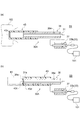
- FIG. 1 is a diagram illustrating a configuration of the light measurement apparatus according to the first embodiment.
- FIG. 2 is an enlarged cross-sectional view showing the configuration of the adapter and catheter kit shown in FIG.
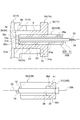
- FIG. 3 is a cross-sectional view for explaining the operation of the position adjusting mechanism.
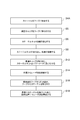
- FIG. 4 is a flowchart showing main steps of the light measurement method according to the first embodiment.
- FIG. 5 is a diagram for explaining the main steps shown in FIG.
- FIG. 6 is a diagram for explaining a main process subsequent to the process shown in FIG.
- FIG. 7 is a diagram for explaining a main process subsequent to the process shown in FIG.
- FIG. 8 is a diagram illustrating a configuration of the light measurement device according to the second embodiment.
- FIG. 9 is a flowchart showing main steps of the light measurement method according to the second embodiment.
- FIG. 10 is a diagram for explaining the main steps shown in FIG.
- FIG. 11 is a diagram for explaining a main process subsequent to the process shown in FIG.
- FIG. 12 is a diagram for explaining a main process subsequent to the process shown in FIG.
- FIG. 13 is a diagram illustrating a configuration of a light measurement apparatus according to the third embodiment.
- 14 is an enlarged cross-sectional view of the configuration of the adapter and catheter kit shown in FIG.
- FIG. 15 is a flowchart showing main steps of the light measurement method according to the third embodiment.
- FIG. 16 is a diagram for explaining the main steps shown in FIG.
- FIG. 17 is a diagram for explaining a main process subsequent to the process shown in FIG. 16.
- FIG. 16 is a diagram for explaining the main steps shown in FIG.
- FIG. 17 is a diagram for explaining a main process subsequent to the process shown in FIG. 16.
- FIG. 16 is
- FIG. 18 is a diagram for explaining a main process subsequent to the process shown in FIG.
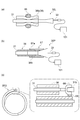
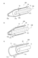
- FIG. 19 is a perspective view showing a cross section of a catheter kit according to Modifications 1, 2, and 3.
- FIG. 20 is a perspective view showing a cross section of a catheter kit according to Modifications 4, 5, and 6.
- FIG. 21 is a side view showing a cross section of a catheter kit according to Modification 7.
- FIG. 22 is a plan view showing a catheter kit according to Modification 8.
- FIG. 23 is a side view showing a cross section of a catheter kit according to Modifications 9, 10, and 11.
- FIG. FIG. 24 is a perspective view showing a cross section of a catheter kit according to Modifications 12 and 13.
- the light measurement device 1 measures the intensity of the laser light L.
- the laser light L is provided from the light source 101 to the catheter kit 30.
- the laser beam L is emitted from the catheter kit 30.
- the light measurement device 1 includes a power meter 2 and an adapter 3 (second adapter).
- the side from which light is emitted in each component is referred to as “tip”.
- the opposite side of the “tip” is the “base end”.
- the end that emits the laser light L is a “tip”.
- the end that receives the laser beam L is a “base end”.
- the power meter 2 includes a housing 4, a light receiving unit 6, a mounting unit 7, and a processing device 8.
- the housing 4 holds a relative positional relationship between the light receiving unit 6 and the mounting unit 7.
- the housing 4 is made of an opaque material.
- the housing 4 forms a closed space together with the adapter 3.
- the light receiving unit 6 is disposed inside the closed space. According to this configuration, stray light can be prevented from entering the light receiving unit 6.
- the light receiving unit 6 receives the laser light L output from the catheter kit 30.
- the light receiving unit 6 includes, for example, a light absorber.
- the light receiving unit 6 converts the absorbed light into heat. Thereafter, the light receiving unit 6 outputs the change in heat as a change in electrical signal. Examples of the light absorber include 3A-P manufactured by Ophir.
- the electrical signal output from the light receiving unit 6 is transmitted to the processing device 8 via a signal cable.
- the processing device 8 obtains the intensity of the light received by the light receiving unit 6 based on the electrical signal. Then, the processing device 8 displays the intensity value.
- the mounting portion 7 is provided at a position facing the light receiving portion 6.
- the attachment portion 7 may be a part of the housing 4.
- the attachment portion 7 defines the position of the catheter kit 30 with respect to the light receiving portion 6.
- the position of the catheter kit 30 with respect to the light receiving unit 6 includes the distance from the distal end of the catheter kit 30 to the light receiving unit 6 in the traveling direction of the laser light L emitted from the catheter kit 30. Furthermore, this position includes the position of the distal end portion of the catheter kit 30 with respect to the light receiving portion 6 in a plane orthogonal to the traveling direction of the laser light L.
- the attachment portion 7 has an upright cylinder portion 7 a protruding from the housing 4. Furthermore, the upright cylinder part 7a has an adapter placement part 7H which is a through hole.
- the catheter kit 30 is disposed on the adapter placement portion 7H via the adapter 3.
- the tip of the adapter placement portion 7H is a tip opening 7Ha provided on the inner wall of the housing 4.
- the proximal end of the adapter placement portion 7 ⁇ / b> H is a proximal end opening 7 ⁇ / b> Hb provided at the end of the attachment portion 7.
- the adapter 3 attaches the catheter kit 30 to the power meter 2.
- the adapter 3 may be made of polyacetal, for example.
- the adapter 3 includes an adapter main body 9 and an adapter flange 11.
- the adapter body 9 and the adapter flange 11 are integrally formed.
- the adapter main body 9 is arranged in the adapter arrangement unit 7H.
- the adapter main body 9 has an adapter front end surface 3a.
- a male screw may be provided on the outer peripheral surface of the adapter body 9.
- the adapter flange 11 is provided on the proximal end side.
- the adapter flange 11 has an adapter base end surface 3b.
- the outer diameter of the adapter flange 11 is larger than the inner diameter of the adapter placement portion 7H.
- the adapter flange 11 may abut against the attachment end surface 7 b of the attachment portion 7.
- the adapter 3 has a hoop placement portion 3H that holds the tip of the catheter kit 30.
- the hoop disposition portion 3H is a hole extending from the adapter base end surface 3b toward the adapter front end surface 3a.
- the base end side of the hoop disposition portion 3H is a base end opening 3Hb provided in the adapter base end surface 3b.
- the base end opening 3Hb may be chamfered (tapered).
- An adapter tip wall 3d is provided on the tip side of the hoop placement portion 3H. When the catheter kit 30 is placed in the hoop placement portion 3H, the tip of the catheter kit 30 hits the adapter tip wall 3d.
- the adapter tip wall 3 d defines the insertion depth of the catheter kit 30 with respect to the adapter 3.
- the adapter tip wall 3d is provided with a light passage portion 3e which is a through hole.
- the light passage part 3 e guides the laser light L emitted from the catheter kit 30 to the light receiving part 6. Therefore, the abutting portion 3c (second butting portion) is configured by the adapter tip wall 3d and the light passage portion 3e.
- the catheter kit 30 includes a catheter 31 and a catheter container 32.
- the catheter 31 contains an optical fiber 33.
- the catheter 31 may have another component 34 required for treatment and examination.
- the optical fiber 33 has an optical fiber distal end portion 33a and an optical fiber proximal end portion 33b.
- the optical fiber tip 33a is inserted into the body. Further, the optical fiber tip 33a emits a laser beam L.
- a light source 101 (see FIG. 1) is connected to the optical fiber base end portion 33b. Then, the laser light L is provided to the optical fiber base end portion 33b.
- the catheter container 32 accommodates the catheter 31.
- the catheter container 32 includes a hoop 36, a holding plug 37 (catheter holding portion), a protective cap 43, and a bellows 46 (see FIG. 1).
- the hoop 36 has a tubular pipe shape.
- the hoop 36 referred to in the present embodiment is used in a medical field.
- the hoop 36 is a resin tube into which the catheter 31 is inserted.
- the hoop 36 may be flexible or not.
- the hoop 36 may have flexibility or may not have flexibility.
- the hoop 36 includes a hoop distal end portion 36a where the catheter distal end portion 31a is disposed, and a hoop proximal end portion 36b where the catheter proximal end portion 31b side is disposed.
- a tip opening 36c is provided in the hoop tip portion 36a. That is, the hoop tip 36a is not closed. In other words, the hoop tip 36a is open.
- the hoop base end portion 36b also has a base end opening 36d. That is, the hoop base end portion 36b is not closed. In other words, the hoop base end portion 36b is open.
- the hoop 36 is provided with a gas introduction hole 36e.
- the gas introduction hole 36 e is provided on the side wall of the hoop 36. The gas introduction hole 36e penetrates from the outer peripheral surface to the inner peripheral surface.
- the relationship between the inner diameter (f) and outer diameter (d) of the hoop 36 and the inner diameter (e) of the light passing portion 3e of the adapter 3 is f ⁇ e ⁇ d. According to the relationship of this dimension, it can suppress that the catheter front-end
- the holding plug 37 is disposed on the hoop base end portion 36b side so as to be press-fit into the base end opening 36d.
- the holding plug 37 includes a catheter placement portion 38, a press-fit portion 39 that is press-fitted into the hoop 36, and a flange portion 41.
- the catheter placement portion 38 is a through hole that holds the catheter 31.
- the holding plug 37 holds the position of the catheter 31 with respect to the hoop 36 when inserted into the hoop 36. That is, the holding plug 37 is fixed to the hoop 36.
- the holding plug 37 holds the catheter 31. Accordingly, the holding plug 37 inserted into the hoop 36 holds the position of the catheter 31 with respect to the hoop 36.
- the catheter placement portion 38 is placed on the catheter proximal end portion 31b side.
- the inner diameter of the catheter placement portion 38 is slightly smaller than the outer diameter of the catheter 31. According to this configuration, the inner peripheral surface of the catheter placement portion 38 is pressed against the outer peripheral surface of the catheter 31. As a result, the position of the catheter 31 with respect to the holding plug 37 is held.
- the press-fitting part 39 is press-fitted into the hoop 36 from the base end opening 36d of the hoop base end part 36b.
- the outer diameter of the press-fit portion 39 is slightly larger than the inner diameter of the hoop 36. According to this configuration, the outer peripheral surface of the press-fit portion 39 is pressed against the inner peripheral surface of the hoop 36.
- the flange portion 41 is provided on the proximal end side of the press-fit portion 39.
- the outer diameter of the flange portion 41 is larger than the inner diameter of the hoop 36.
- the protective cap 43 is attached to the hoop 36.
- the protective cap 43 has a cylindrical shape with one end closed and the other end opened.
- the protective cap 43 may be formed of acrylic, for example.
- the protective cap 43 closes the tip opening 36c of the hoop tip 36a. According to this configuration, the catheter tip 31a is protected.
- the protective cap 43 transmits the laser light L emitted from the catheter tip 31a.
- the protective cap 43 has a cap front end portion 43a and a cap base end portion 43b.
- the cap tip portion 43a has a transmission window portion 43c.
- the transmission window 43c closes the tip opening 36c. Further, the transmission window 43c transmits the laser light L.
- the cap base end portion 43b has a base end opening 43Hb of a hoop arrangement portion 43H into which the hoop 36 can be inserted.
- the bellows 46 is disposed between the hoop 36 and the holding plug 37.
- the bellows 46 which is a so-called bellows, can freely expand and contract in the axial direction.
- the bellows 46 has elasticity to maintain a predetermined length when no external force is applied. For example, when the bellows 46 is pressed in the axial direction, the length of the bellows 46 is reduced. On the other hand, when the pressing is stopped, the length of the bellows 46 returns to the length before the pressing.
- the bellows 46 has a bellows tip end 46a and a bellows base end 46b.
- the bellows tip 46a abuts on the hoop base end 36b.
- the bellows base end portion 46 b abuts on the flange portion 41 of the holding plug 37.
- interval between the base end surface of the hoop base end part 36b and the front end surface of the flange part 41 of the holding plug 37 is maintained constant (refer the space
- the restoring force of the bellows 46 is generated.
- the restoring force is smaller than the frictional force between the press-fit portion 39 and the inner peripheral surface of the hoop 36. Accordingly, the state in which the holding plug 37 is pushed in is maintained (see the interval D2 in the part (b) of FIG. 3).
- the bellows 46 may not generate a restoring force.
- the bellows 46 is in an expanded state (that is, the state of the (a) portion in FIG. 3) and a contracted state (the state of the (b) portion in FIG. 3) without requiring another component. , Can be maintained respectively.
- the bellows 46 and the holding plug 37 constitute a position adjusting mechanism 47.
- the catheter 31 is held in the first position. In this first position, the catheter distal end portion 31a is disposed closer to the proximal end with respect to the hoop distal end portion 36a (see the portion (a) in FIG. 3).
- the distance from the distal end surface of the hoop distal end portion 36a to the distal end surface of the catheter distal end portion 31a is defined as D3.
- the catheter 31 is held at the second position. In the second position, the positions of the hoop tip portion 36a and the catheter tip portion 31a coincide with each other (see the portion (b) in FIG. 3).
- Step S2 is performed (see part (a) of FIG. 5).
- the protective cap 43 is attached to the hoop 36.
- the protective cap 43 is completely covered with the hoop 36.
- the tip surface of the hoop tip 36a is brought into contact with the inner surface of the cap tip 43a.
- a gap may be provided between the tip surface of the hoop tip portion 36a and the inner surface of the cap tip portion 43a.
- This predetermined length corresponds to, for example, the distance from the distal end surface of the hoop distal end portion 36a to the distal end surface of the catheter distal end portion 31a when in the storage state.
- process S4 may be performed after process S2 as mentioned above. Moreover, you may perform process S2 after process S4.
- the catheter 31 is accommodated in the hoop 36.
- the hoop tip 36 a is closed by a protective cap 43.
- the hoop base end portion 36 b is closed by a holding plug 37 and a bellows 46.
- the hoop 36 has a gas introduction hole 36e.
- the sterilizing gas G is introduced into the hoop 36 from the gas introduction hole 36e. Therefore, according to the gas introduction hole 36e, the catheter 31 accommodated in the hoop 36 can be reliably sterilized. After the sterilization gas G is filled, the sterilization gas G is degassed from the chamber.
- step S12 is performed (see part (a) of FIG. 7).
- the catheter kit 30 is attached to the power meter 2. More specifically, the adapter 3 is screwed into the mounting portion 7 of the power meter 2. Then, the distal end side (protective cap 43 side) of the catheter kit 30 is inserted into the adapter 3.
- step S16 is performed (see part (b) of FIG. 7). Specifically, the catheter kit 30 is pulled out from the adapter 3. Next, the holding plug 37 is pulled out from the hoop 36. As a result, the catheter 31 is removed from the hoop 36. In step S18 (not shown), a predetermined treatment or examination is performed using the catheter 31.
- the attachment portion 7 defines the position of the hoop 36 relative to the light receiving portion 6.
- the catheter kit 30 further includes a position adjusting mechanism 47 that is provided at the hoop base end portion 36 b and changes the position of the catheter tip portion 31 a relative to the hoop tip portion 36 a in the extending direction of the hoop 36.
- a position adjusting mechanism 47 that is provided at the hoop base end portion 36 b and changes the position of the catheter tip portion 31 a relative to the hoop tip portion 36 a in the extending direction of the hoop 36.
- the catheter kit 30 further includes a protective cap 42 that is attached to the hoop tip 36a and closes the tip opening 36c of the hoop tip 36a. According to this configuration, the catheter tip 31a can be protected.
- the catheter kit 30 further includes a protective cap 43 attached to the hoop 36 and an adapter 3 that places the hoop 36 attached with the protective cap 43 on the attachment portion 7.
- the hoop 36 has a hoop tip portion 36a including a tip opening 36c and a catheter tip portion 31a.
- the protective cap 43 is attached to the hoop tip portion 36a.
- the protective cap 43 has a cap tip portion 43a including a transmission window portion 43c that closes the tip opening 36c and transmits the laser light L emitted from the optical fiber 33.
- the adapter 3 has a contact portion 3c against which the cap tip portion 43a is abutted.
- the protective cap 43 having the transmission window portion 43 c is disposed between the catheter distal end portion 31 a and the light receiving portion 6.
- the transmission window portion 43c closes the tip opening 36c of the hoop tip portion 36a. Therefore, the catheter tip 31a can be protected.
- the position of the hoop 36 relative to the light receiving unit 6 is defined in step S12 in which the hoop 36 is disposed on the attachment unit 7.
- step S14 for obtaining the intensity of the laser beam L it is possible to measure the intensity of the laser beam L while the catheter 31 is housed in the hoop 36. Therefore, the cleanliness of the catheter 31 can be maintained. Furthermore, there is no need to remove the catheter 31 from the hoop 36. As a result, the process required for measuring the laser beam L can be simplified. Therefore, according to the light measurement method, the cleanliness of the catheter 31 can be maintained and the light intensity can be easily checked.
- Step S2A is performed (part (a) of FIG. 10).
- the protective cap 43 is attached to the hoop 36.
- the protective cap 43 is not completely covered with the hoop 36.
- the tip surface of the hoop tip 36a is not brought into contact with the inner surface of the cap tip wall 43d. That is, a predetermined distance D3 is provided between the inner surface of the cap tip wall 43d and the tip surface of the hoop tip portion 36a.
- Step S4A is performed (see part (b) of FIG. 10).
- the catheter 31 is accommodated in the hoop 36.
- the protective cap 43 is attached to the hoop 36 so as to provide a predetermined distance D ⁇ b> 3 between the protective cap 43 and the hoop 36.
- the catheter tip 31a is disposed so as to coincide with the hoop tip 36a.
- a predetermined distance D3 is also formed between the catheter tip 31a and the cap tip wall 43d. Therefore, since the catheter tip 31a does not hit the inner surface of the cap tip wall 43d, the catheter tip 31a can be protected.
- Step S6 is performed (see part (c) of FIG. 10).
- the specific process is the same as the process S6 according to the first embodiment.
- step S8 is performed (see part (a) of FIG. 11). Specific steps are the same as step S8 according to the first embodiment.
- Step S9 is performed (see part (b) of FIG. 11).
- the protective cap 43 is pushed into the hoop 36 side.
- the inner surface of the cap tip wall 43d comes into contact with the tip surface of the hoop tip portion 36a.
- the position of the catheter tip 31a matches the position of the hoop tip 36a.
- step S12 see the part (a) in FIG. 12
- step S14 see part (a) in FIG. 12
- step S14 the light source 101 is operated.
- step S16 see part (b) of FIG. 12
- step S18 a predetermined treatment or examination is performed using the catheter 31.
- the light measurement method according to the second embodiment can maintain the cleanliness of the catheter 31 and can easily check the light intensity.
- the catheter kit 30 ⁇ / b> B of the third embodiment is different from the catheter kit 30 of the first embodiment in that the catheter container 32 ⁇ / b> B does not have the protective cap 43 and the position adjustment mechanism 47.
- the light measurement apparatus 1A according to the third embodiment will be described with respect to the light measurement apparatus 1A according to the third embodiment, and then the light measurement method according to the third embodiment will be described.
- the light measurement device 1A has an adapter 3A.
- the adapter 3 ⁇ / b> A (first adapter) according to the third embodiment directly holds the hoop 36 without using the protective cap 43. Accordingly, the tip surface of the hoop tip portion 36a comes into contact with the contact portion 3c (first butting portion).
- Step S4A is performed (see part (a) of FIG. 16). Similar to step S4A of the second embodiment, in step S4A, the catheter tip 31a is disposed so as to coincide with the hoop tip 36a.
- Step S5 is performed (see part (b) of FIG. 16).
- the protective cap 42 (closed portion) is attached to the hoop 36.
- the protective cap 42 closes the tip opening 36 c of the hoop 36.
- the protective cap 42 has a hoop holding part 42a.
- the inner diameter of the hoop holding portion 42 a is slightly smaller than the outer diameter of the hoop 36. According to this configuration, the inner peripheral surface of the hoop holding portion 42 a is pressed against the outer peripheral surface of the hoop 36 in a state where the hoop 36 is inserted into the hoop holding portion 42 a. Accordingly, the protective cap 42 can be prevented from falling off.
- the protective cap 42 and the hoop 36 have flexibility due to the material. Therefore, the protective cap 42 can be easily removed.
- Step S6 is performed (see part (c) of FIG. 16).
- the specific process is the same as the process S6 according to the first embodiment.
- Step S8 is performed (see part (a) of FIG. 17). Specific steps are the same as step S8 according to the first embodiment.
- step S12 see part (a) of FIG. 18
- step S14 the light source 101 is operated.
- step S16 the catheter kit 30B is pulled out from the adapter 3A.
- step S18 a predetermined treatment or examination is performed using the catheter 31.
- the light measurement device 1A and the light measurement method according to the third embodiment can easily maintain the cleanliness of the catheter 31 and can easily check the light intensity as in the first embodiment.
- the light measuring device 1A further includes an adapter 3A for arranging the hoop 36 on the attachment portion 7.
- the adapter 3A has a contact portion 3c against which the hoop tip portion 36a is abutted. According to this configuration, the laser beam L is emitted toward the light receiving unit 6 through the tip opening 36c in the hoop tip portion 36a. As a result, the laser beam L emitted from the catheter tip 31a is directly incident on the light receiving unit 6 without being attenuated. Accordingly, it is possible to obtain the intensity of the laser beam L with high accuracy.
- the present invention has been described in detail above based on the embodiments. However, the present invention is not limited to the above embodiment. The present invention can be variously modified without departing from the gist thereof.
- the catheter kit is not limited to the configuration shown in the above embodiments. The catheter kit can take a variety of configurations.
- the catheter kits 30 and 30A according to the first embodiment and the second embodiment had a configuration (protection cap 42) for closing the tip opening 36c of the hoop tip portion 36a.
- the configuration shown in the following modifications 1, 2, and 3 may be used to close the tip opening 36c.
- the catheter kit 30 ⁇ / b> C according to Modification 1 has a protective cap 48.
- the protective cap 48 may be detachable from the hoop 36. Further, the protective cap 48 may be fixed to the hoop 36 with an adhesive or the like so that it cannot be removed from the hoop 36.
- the protective cap 48 is formed of a material that is transparent to the laser light L.
- the protective cap 48 has a cap body portion 48a and a flange portion 48b.
- the cap main body 48a has a cylindrical shape. The cap body 48a is fitted into the hoop tip 36a.
- the flange portion 48b is provided on the distal end side of the cap main body portion 48a.
- the flange portion 48b has a disk shape.
- the flange portion 48b has substantially the same diameter as the diameter of the outer peripheral surface of the hoop 36. That is, the diameter of the flange portion 48b is larger than the inner diameter of the tip opening 36c. According to this configuration, the proximal end surface of the flange portion 48b abuts on the distal end surface of the hoop distal end portion 36a. As a result, the insertion depth of the protective cap 48 can be defined.
- the protective cap 48 has a catheter placement portion 48c that defines the position of the catheter tip portion 31a.
- the catheter placement portion 48 c causes the central axis A 31 of the catheter 31 to be along the central axis A 36 of the hoop 36.
- the catheter placement portion 48 c defines the position of the catheter distal end portion 31 a in the diametrical direction of the hoop 36.
- the catheter placement portion 48c defines the direction of the catheter 31 (that is, the emitting direction of the laser light L) to a predetermined direction. According to such a catheter placement portion 48c, the position and posture of the catheter tip portion 31a with respect to the light receiving portion 6 can be accurately defined. Therefore, it is possible to obtain an accurate light intensity value. In addition, it is possible to suppress the occurrence of variations in light intensity for each measurement.
- the catheter placement portion 48c is a tapered hole and extends from the proximal end surface of the cap body portion 48a toward the flange portion 48b. The diameter of the catheter placement portion 48c gradually decreases toward the flange portion 48b.
- the catheter placement portion 48c has a proximal end opening 48d provided on the proximal end surface and a bottom portion 48e provided on the flange portion 48b side.
- the inner diameter of the proximal end opening 48 d is larger than the outer diameter of the catheter 31.
- the inner diameter of the base end opening 48 d is slightly smaller than the inner diameter of the hoop 36.
- the diameter of the bottom 48e is smaller than the outer diameter of the catheter 31.
- the distal end surface of the catheter distal end portion 31a does not contact the bottom portion 48e.
- the catheter distal end portion 31a can be suitably guided to the catheter arrangement portion 48c.
- the protective cap 48 is used, the distal end surface of the catheter distal end portion 31a does not protrude from the distal end surface of the hoop distal end portion 36a. Therefore, the position of the catheter tip 31a in the emission direction of the laser light L is defined.
- the laser light L passes through the cap main body portion 48a and the flange portion 48b and enters the light receiving portion 6.
- the shape of the catheter placement portion 48c may be configured such that the optical axis of the laser light L intersects the tapered surface of the catheter placement portion 48c (see arrow W1).
- the shape of the catheter placement portion 48c may not be such that the optical axis of the laser light L intersects the tapered surface. That is, the shape of the catheter placement portion 48c may be configured such that the optical axis of the laser light L intersects the bottom portion 48e (see arrow W2).
- the catheter kit 30 ⁇ / b> D according to the modified example 2 can also regulate the position of the catheter tip 31 a like the catheter kit 30 ⁇ / b> C of the modified example 1.
- the catheter kit 30D has a protective cap 49.
- the protective cap 49 may be detachable from the hoop 36.
- the protective cap 49 may be fixed to the hoop 36 with an adhesive or the like so that it cannot be removed.
- the protective cap 49 has a main body cylinder part 49a and a tapered cylinder part 49b.
- the main body cylinder portion 49a is a cylindrical member that covers the hoop tip portion 36a.
- the inner diameter of the main body cylinder portion 49 a is substantially the same as or slightly smaller than the outer diameter of the hoop 36.
- the tapered cylinder portion 49b is provided on the distal end side of the main body cylinder portion 49a.
- the tapered tube portion 49b has a truncated cone shape.
- the outer diameter of the tapered cylindrical portion 49b gradually decreases from the portion continuous with the main body cylindrical portion 49a toward the distal end side.
- the tapered cylinder portion 49b has a tapered hole.
- the inner diameter of the tapered hole gradually decreases toward the tip. This tapered hole is the catheter placement portion 49c.
- the catheter placement portion 49c is a tapered hole.
- the tapered hole extends from the boundary between the main body tube portion 49a and the taper tube portion 49b toward the tip.
- the diameter of the catheter placement portion 49c gradually decreases toward the tip.
- the catheter placement portion 49c has a proximal end opening 49d and a distal end bottom portion 49e.
- the inner diameter of the base end opening 49d is substantially the same as the outer diameter of the hoop 36.
- the diameter of the tip bottom 49e is smaller than the outer diameter of the catheter 31. Therefore, the distal end surface of the catheter distal end portion 31a does not contact the distal end bottom portion 49e.
- the catheter distal end portion 31a when the catheter 31 is inserted into the hoop 36 from the proximal end side toward the distal end side, the catheter distal end portion 31a can be suitably guided to the catheter arrangement portion 49c.
- the protective cap 49 When the protective cap 49 is used, the distal end surface of the catheter distal end portion 31a protrudes from the distal end surface of the hoop distal end portion 36a. According to this configuration, the catheter tip 31a can be brought close to the light receiving unit 6 in a state where the catheter tip 31a is protected.
- the laser light L passes through the tapered tube portion 49b and enters the light receiving portion 6.
- the shape of the catheter placement portion 49c intersects the tip bottom portion 49e without the optical axis of the laser beam L intersecting the tapered surface (see arrow W3).
- the shape of the catheter placement portion 49c may be such that the optical axis of the laser light L intersects the tapered surface.
- the catheter kit 30 ⁇ / b> E according to the modification 3 has a protective lid part 51.
- the protective lid 51 has a disk shape.
- the protective lid 51 has an outer peripheral surface 51a, a distal end surface 51b, and a proximal end surface 51c.
- the outer diameter of the protective lid 51 is substantially equal to the inner diameter of the hoop 36.
- the protective lid 51 is fitted into the tip opening 36c of the hoop tip 36a.
- the front end surface 51b is exposed outside.
- the base end surface 51c faces the inner side of the hoop 36.
- the catheter distal end portion 31a faces the proximal end surface 51c.
- the laser light L emitted from the catheter tip 31 a enters the light receiving unit 6 after passing through the protective lid 51.
- the protective lid 51 is formed of a material that is transparent to the laser light L.
- the protective lid 51 is fixed to the hoop 36 with an adhesive or the like so that it cannot be removed. That is, the protective lid 51 is integrated with the hoop 36. Specifically, the outer peripheral surface 51 a of the protective lid 51 is fixed to the inner peripheral surface of the hoop 36 by adhesion or the like. According to this configuration, the protective lid 51 does not fall off the hoop 36. Therefore, the catheter tip 31a can be reliably protected.
- the distal end of the catheter kit 30B according to the third embodiment was opened.
- the catheter kit having the opened distal end opening 36c may have a configuration shown in the following modifications 4, 5, and 6.
- the catheter kit 30 ⁇ / b> F according to Modification 4 has a hoop 52.
- the hoop 52 has a catheter placement portion 52b provided at the hoop tip 52a.
- the catheter placement portion 52 b causes the central axis A ⁇ b> 31 of the catheter 31 to be along the central axis A ⁇ b> 52 of the hoop 52.
- the catheter placement portion 52b has a through hole 52c and a tapered portion 52d.
- the through holes 52 c are arranged along the central axis A 52 of the hoop 52.
- the tapered portion 52d constitutes the catheter placement portion 52b.
- the through hole 52c includes a distal end opening 52e formed on the distal end surface of the hoop distal end portion 52a and a proximal end opening 52f formed on the proximal end side.
- the tapered portion 52 d includes a distal end portion 52 g that is continuous with the proximal end opening 52 f and a proximal end portion 52 h that is continuous with the inner peripheral surface of the hoop 52.
- the inner diameter of the through hole 52 c is smaller than the inner diameter of the hoop 52. Therefore, the inner diameter of the tapered portion 52d gradually decreases from the proximal end portion 52h toward the distal end portion 52g. Further, the inner diameter of the through hole 52 c is smaller than the outer diameter of the catheter 31. Therefore, the catheter tip 31a is not inserted into the through hole 52c.
- the catheter placement portion 52 b is a part of the hoop 52.
- the catheter placement portion 52b is a portion of the hoop tip portion 52a that gradually increases in thickness toward the tip.
- the catheter tip portion 31a does not protrude from the hoop tip portion 52a. Therefore, the catheter tip 31 a does not protrude from the adapter tip surface 53 a of the adapter 53. Therefore, the position of the catheter tip 31a in the emission direction of the laser light L is defined.
- the laser beam L emitted from the catheter 31 is incident on the light receiving unit 6 through the through hole 52c (see arrow W4). Accordingly, the laser light L emitted from the catheter 31 is directly incident on the light receiving unit 6. As a result, a highly accurate measurement result can be obtained. Further, the laser beam L passes through the through hole 52c. Therefore, the material constituting the hoop 52 may or may not be translucent to the laser light L.
- the hoop 52 may be formed of a light transmissive material. Further, the hoop 52 may be formed of a material that does not have translucency.
- the catheter kit 30G according to the modified example 5 has a hoop 54.
- the hoop 54 has a hoop main body portion 54a and a protruding cylinder portion 54b.
- the hoop body 54a has a hoop tip 54d including a tip surface 54c.
- the central axis of the protruding cylinder part 54b overlaps with the central axis of the hoop body part 54a.
- the protruding cylinder portion 54b protrudes from the distal end surface 54c.
- the outer diameter of the protruding cylinder part 54b is smaller than the outer diameter of the hoop body part 54a. Therefore, the front end surface 54c of the hoop main body 54a and the outer peripheral surface 54e of the protruding cylindrical portion 54b form a stepped portion.
- the protruding cylinder portion 54b protrudes from the tip opening 56b of the adapter tip portion 56a.
- the front end surface 54c of the hoop main body 54a abuts on the inner surface of the adapter front end 56a.
- the front end surface 54 c of the hoop main body 54 a defines the insertion depth of the hoop 54 into the adapter 56.
- the hoop 54 has a catheter placement portion 54f.
- the catheter placement portion 54 f is a part of the hoop 54.
- the catheter placement portion 54f is a hole having a tapered shape.
- the inner diameter of the catheter placement portion 54f gradually decreases from the proximal end side toward the distal end side.
- the proximal end portion 54g of the catheter placement portion 54f is provided in the hoop main body portion 54a.
- the inner diameter of the base end portion 54g is equal to the inner diameter of the hoop main body portion 54a.
- the distal end portion 54h of the catheter placement portion 54f is an opening provided on the distal end surface 54c of the protruding cylinder portion 54b.
- the inner diameter of the tip end portion 54 h is smaller than the inner diameter of the hoop 54. Furthermore, the inner diameter of the distal end portion 54 h is smaller than the outer diameter of the catheter 31. At a position corresponding to the distal end surface 54c of the hoop body 54a, the inner diameter of the catheter placement portion 54f is larger than the outer diameter of the catheter 31.
- the catheter distal end portion 31a when the catheter 31 is inserted into the catheter placement portion 54f, the catheter distal end portion 31a is more distal than the position corresponding to the distal end portion 54h of the hoop main body portion 54a that is larger than the outer diameter of the catheter 31. Be placed. Therefore, the catheter tip 31 a can be brought closer to the light receiving unit 6. As a result, accurate light intensity can be obtained. Further, the opening provided in the protruding cylinder portion 54 b is smaller than the outer diameter of the catheter 31. As a result, the catheter distal end portion 31a does not protrude toward the distal end side from the protruding cylindrical portion 54b. Therefore, the protruding cylinder part 54b protects the catheter tip part 31a.
- the catheter kit 30 ⁇ / b> H according to the modified example 6 has a hoop 57.
- the hoop 57 includes a hoop main body portion 57a and a hoop flange portion 57b.
- the hoop body 57a has a hoop tip surface 57c.
- the central axis of the hoop flange portion 57b overlaps with the central axis of the hoop body portion 57a.
- the hoop flange portion 57b is provided at a position separated from the hoop distal end surface 57c of the hoop main body portion 57a by a predetermined distance toward the base end side.
- the predetermined distance is, for example, larger than the distance from the adapter front end surface 58a of the adapter 58 to the adapter base end surface 58b.
- the outer diameter of the hoop flange portion 57b is larger than the inner diameter of the hoop arrangement portion 58d of the adapter 58. Therefore, when the hoop 57 is inserted into the adapter 58, the front end surface 57 h of the hoop flange portion 57 b comes into contact with the adapter 58. More specifically, the front end surface 57h of the hoop flange portion 57b contacts the adapter base end surface 58b.
- the hoop flange portion 57 b defines the insertion depth of the hoop 57 into the adapter 58.
- the distance from the position where the hoop flange portion 57b is provided to the hoop front end surface 57c is larger than the distance from the adapter front end surface 58a to the adapter base end surface 58c. Therefore, when the hoop flange portion 57b contacts the adapter 58, the hoop tip surface 57c protrudes from the adapter tip surface 58a.
- the hoop 57 has a catheter placement portion 57e.
- the catheter placement portion 57e is a part of the hoop 57.
- the catheter placement portion 57e is a hole having a tapered shape.
- the inner diameter of the catheter placement portion 57e gradually decreases from the proximal end side toward the distal end side. Specifically, the inner diameter of the proximal end portion 57f of the catheter placement portion 57e is equal to the inner diameter of the hoop main body portion 57a.
- the distal end portion 57g of the catheter placement portion 57e is an opening provided in the hoop distal end surface 57c.
- the inner diameter of the tip portion 57 g is smaller than the inner diameter of the hoop 57.
- the inner diameter of the distal end portion 57g is smaller than the outer diameter of the catheter 31.
- the inner diameter of the catheter placement portion 57e is larger than the outer diameter of the catheter 31.
- the catheter tip portion 31a when the catheter 31 is inserted into the catheter placement portion 57e, the catheter tip portion 31a is placed on the tip side of the adapter tip surface 58a. Therefore, the catheter distal end portion 31 a is closer to the light receiving portion 6. As a result, accurate light intensity can be obtained. Further, the opening provided in the protruding cylinder portion 54 b is smaller than the outer diameter of the catheter 31. As a result, the catheter distal end portion 31a does not protrude toward the distal end side from the hoop distal end surface 57c. Therefore, the protruding cylinder part 54b protects the catheter tip part 31a.
- the catheter kit 30 has a position adjusting mechanism 47 that switches the position of the catheter 31 with respect to the hoop 36.
- the specific configuration of the position adjustment mechanism may be the configuration shown in the following modified examples 7 and 8.
- the catheter kit 30J according to the modified example 7 includes a position adjusting mechanism 59 having a configuration different from that of the third embodiment.
- the position adjustment mechanism 59 is a tube 59a formed of silicone rubber or the like.
- the tube 59 a is disposed between the hoop 36 and the holding plug 61.
- the tube 59a maintains and changes the distance between the hoop base end portion 36b and the holding plug distal end surface 61a.
- the hoop base end portion 36b is inserted into the tube distal end portion 59b.
- the press-fit portion 61b of the holding plug 61 is inserted into the tube base end portion 59c.
- the position adjustment mechanism 59 has a double structure including the tube 59a and the hoop 36.
- the tube base end portion 59 c is fixed to the holding plug 61.
- the tube distal end portion 59b is slidable with respect to the hoop base end portion 36b.
- Such a configuration can be realized by setting the inner diameter of the tube distal end portion 59b and the outer diameter of the hoop base end portion 36b to predetermined dimension values.
- the tube 59a maintains the interval between the hoop base end portion 36b and the holding plug distal end surface 61a at a predetermined interval.
- the catheter distal end portion 31a is disposed on the proximal end side with respect to the hoop distal end portion 36a (first position). That is, the catheter tip 31a is protected by the hoop 36.
- the holding plug 61 when measuring the laser beam L using the catheter kit 30J, the holding plug 61 is pushed into the distal end side. Then, slip occurs between the tube distal end portion 59b and the hoop base end portion 36b. As a result, the tube 59a and the holding plug 61 move together toward the distal end side. That is, the space
- the catheter kit 30K according to the modification 8 may include a position adjustment mechanism 62 having still another configuration.
- the position adjusting mechanism 62 includes a guide pin 62a and a guide groove 62b. According to these guide pins 62a and guide grooves 62b, the state in which the catheter tip 31a is protected and the state in which the laser light L is measured using the catheter kit 30K are switched reliably. Furthermore, the position adjustment mechanism 62 can maintain each state reliably.
- the catheter kit 30K includes a tube 63. The tube 63 is disposed between the hoop 64 and the holding plug 65. That is, the position adjustment mechanism 62 according to the modified example 8 has a so-called double structure, similarly to the position adjustment mechanism 62 according to the modified example 7.
- the guide groove 62b is provided on the outer peripheral surface of the hoop base end portion 64a.
- the guide groove 62 b may penetrate the side wall of the hoop 64.
- the shape which has a bottom part may be sufficient as the guide groove 62b.
- the guide groove 62b includes a first restricting portion 62c and a second restricting portion 62d extending in the circumferential direction, and a connecting groove portion 62e extending in the axial direction.
- One end of the first restricting portion 62c and one end of the second restricting portion 62d are connected by a connecting groove portion 62e.
- the connecting groove 62 e extends in the axial direction of the hoop 64.
- the 1st control part 62c is provided in the hoop base end surface side.
- the second restricting portion 62d is provided on the tip side of the first restricting portion 62c.
- the distance from the first restricting portion 62c to the second restricting portion 62d corresponds to the moving distance of the catheter 31.
- the guide pin 62 a is provided on the inner peripheral surface of the tube 63.
- the guide pin 62a is a cylindrical protrusion.
- the guide pin 62a extends along the radial direction of the tube 63 from the inner peripheral surface.
- the diameter of the guide pin 62a is substantially the same as or slightly smaller than the guide groove 62b.
- the guide pin 62a when storing the catheter kit 30K, the guide pin 62a is fitted into the first restricting portion 62c.
- the catheter distal end portion 31a is in a protected state arranged on the back side (first position) of the hoop 64.
- the first restricting portion 62c extends in the circumferential direction. As a result, the guide pin 62a does not move in the axial direction. Therefore, since the catheter tip 31a is disposed at the back of the hoop 64, the protected state can be reliably maintained.
- the tube 63 is rotated in the direction in which the first restricting portion 62c extends. If it does so, the guide pin 62a will move to the base end part of the connection groove part 62e. Then, the guide pin 62a is moved along the connecting groove 62e. That is, the tube 63 and the holding plug 65 are moved to the distal end side. By this movement, the catheter tip 31a coincides with the hoop tip 36a. And after moving the guide pin 62a to the front-end
- the catheter tip 31a is in a measurement state that coincides with the hoop tip 36a (second position).
- the second restricting portion 62d extends in the circumferential direction similarly to the first restricting portion 62c.
- the guide pin 62a does not move in the axial direction. Accordingly, it is possible to reliably maintain the state in which the catheter distal end portion 31a is disposed at the hoop distal end portion 36a.
- the catheter kit 30 has a mechanism for holding the position of the catheter 31 with respect to the hoop 36.
- the specific configuration of this mechanism may be the configuration shown in the following modifications 9, 10, and 11.
- the catheter kit 30 ⁇ / b> L according to Modification 9 may have a clip 66 as a mechanism for holding the position of the catheter 31.
- the clip 66 is attached to the hoop base end portion 36b.
- the clip 66 generates a force that crushes the hoop 36 in the radial direction.
- the inner peripheral surface of the hoop 36 is pressed against the outer peripheral surface of the catheter 31.
- the clip 66 is attached so as to sandwich the hoop 36 from the radial direction. Therefore, the side wall of the hoop 36 crushed by the clip 66 sandwiches the catheter 31.
- the position of the catheter 31 with respect to the hoop 36 is maintained. Further, when moving the hoop 36, the clip 66 is removed. According to the holding mechanism by the clip 66, the state of holding the catheter 31 and the state in which the catheter can be moved can be easily switched.
- the catheter kit 30P according to the modified example 10 may have a tube 67 as a holding mechanism.
- This configuration is similar to the configuration of Modification 7. That is, it has a double structure.
- the tube distal end portion 67a is configured not to slide with respect to the hoop base end portion 36b.
- the inner diameter of the tube 63 is smaller than the outer diameter of the hoop 36.
- the catheter kit 30Q according to the modification 11 may have a clamp 68 as a holding mechanism.
- the clamp 68 is a U-shaped part to which the catheter base end portion 31b can be attached and detached.
- the clamp 68 includes a fixing portion 69 that is fixed to the outer peripheral surface of the hoop 36.
- the catheter proximal end portion 31b is inserted from the opening of the clamp 68 along the radial direction. As a result, the catheter proximal end portion 31 b is fixed to the clamp 68.
- the clamp 68 is fixed to the hoop 36 by a fixing portion 69. Accordingly, the catheter 31 is held against the hoop 36.
- the catheter kit 30B according to the third embodiment had a protective cap 42 attached to the hoop tip 36a during storage.
- the configuration for protecting the catheter distal end portion 31a arranged so as to coincide with the hoop distal end portion 36a may be configured as shown in the following modified examples 12 and 13.
- the catheter kit 30 ⁇ / b> S according to the modified example 12 has a protective cap 72.
- the protective cap 72 has a configuration similar to the protective cap 72 of the second modification.
- the difference with respect to the protective cap 49 of Modification 2 is that the protective cap 72 according to Modification 12 can be moved relative to the hoop 36.
- the protective cap 72 when storing the catheter kit 30S, the protective cap 72 is shallowly placed on the hoop tip 36a. According to this configuration, a gap is provided between the cap tip portion 72a of the protective cap 72 and the catheter tip portion 31a. Accordingly, the catheter tip 31a can be suitably protected.
- the protective cap 72 when measuring the laser beam L using the catheter kit 30S, the protective cap 72 is pushed into the hoop 36 side. By this pushing, the space
- the central axis A31 of the catheter 31 is along the central axis A36 of the hoop 36. Accordingly, variations in the position and posture of the catheter tip 31a from which the laser beam L is emitted are suppressed. As a result, accurate light intensity measurement can be performed.
- the catheter kit 30 ⁇ / b> R according to the modified example 13 has a protective tube 71.
- the protective tube 71 is attached to the hoop tip 36a.
- the protective tube 71 has a tube base end portion 71a that receives the hoop tip end portion 36a and a tube tip end portion 71b.
- the tube base end 71a is attached to the hoop tip 36a, the substantial tip of the hoop 36 is the tube tip 71b.
- the tube tip portion 71b protrudes further to the tip side than the hoop tip portion 36a.
- the catheter distal end portion 31a is disposed on the proximal end side with respect to the tube distal end portion 71b. According to this configuration, the protective tube 71 protects the catheter tip 31a. And when measuring the laser beam L, the protection tube 71 is removed.
- the first to sixth modifications 12, 12, and 13 related to the tip shape, the modified examples 7 and 8 related to the position adjusting mechanism, and the modified examples 9, 10, and 11 related to the holding mechanism are required for the catheter kit. Depending on the, you may combine freely.
- protective cap 42a Hoop holding part, 43 ... Protective cap, 43a ... Cap tip part, 43b ... Cap base end part, 43d ... Cap tip wall, 43c ... Transmission window part, 43H ... Hoop placement part, 43Hb ... Base end opening, 46 ... Bellows 46a ... Bellow tip portion, 46b ... Bellow proximal end portion, 47 ... Position adjustment mechanism, 48 ... Protection cap, 48a ... Cap body portion, 48b ... Flange portion, 48c ... Catheter placement portion, 48d ... Base end opening, 48e ... Bottom, 49 ... Protective cap, 49a ... Main body cylinder, 49b ... Tapered cylinder, 49c ... Catheter placement part, 49d ...
- catheter placement part 54g ... proximal end part, 54h ... tip part, 56 ... adapter, 56a ... adapter tip part, 56b ... tip opening, 57 ... hoop, 57a ... hoop body part, 57b ... hoop flange part, 57c ... Hoop distal end surface, 57e ... catheter placement portion, 57f ... proximal end portion, 57g ... distal end portion, 57h ... distal end surface, 58 ... adapter, 58a ... adapter distal end surface, 58b ... adapter 59d ... tube adjusting portion, 59a ... tube, 59b ... tube tip, 59c ...
Landscapes
- Physics & Mathematics (AREA)
- Health & Medical Sciences (AREA)
- Optics & Photonics (AREA)
- Surgery (AREA)
- Life Sciences & Earth Sciences (AREA)
- General Physics & Mathematics (AREA)
- Molecular Biology (AREA)
- Public Health (AREA)
- Engineering & Computer Science (AREA)
- Biomedical Technology (AREA)
- Heart & Thoracic Surgery (AREA)
- Medical Informatics (AREA)
- Nuclear Medicine, Radiotherapy & Molecular Imaging (AREA)
- Animal Behavior & Ethology (AREA)
- General Health & Medical Sciences (AREA)
- Otolaryngology (AREA)
- Veterinary Medicine (AREA)
- Electromagnetism (AREA)
- Chemical & Material Sciences (AREA)
- Analytical Chemistry (AREA)
- Media Introduction/Drainage Providing Device (AREA)
- Optical Couplings Of Light Guides (AREA)
- Laser Surgery Devices (AREA)
- Investigating Or Analysing Materials By Optical Means (AREA)
- Measuring And Recording Apparatus For Diagnosis (AREA)
- Radiation-Therapy Devices (AREA)
Abstract
Description
図1に示すように、光測定装置1は、レーザ光Lの強度を測定する。レーザ光Lは、光源101からカテーテルキット30に提供される。そしてレーザ光Lは、カテーテルキット30から出射される。光測定装置1は、パワーメータ2と、アダプタ3(第2アダプタ)と、を有する。以下の説明において、各構成要素において光が出射される側を「先端」とする。「先端」の逆側を「基端」とする。例えば、カテーテルキット30において、レーザ光Lを出射する端部は「先端部」である。レーザ光Lを受け入れる端部は「基端部」である。
第2実施形態に係る光測定装置及びカテーテルキットについて説明する。図8に示すように、第2実施形態のカテーテルキット30Aは、位置調整機構47を有しない点で、第1実施形態のカテーテルキット30と相違する。一方、第2実施形態の光測定装置1は、第1実施形態の光測定装置1と同様の構成を有する。以下、図9のフロー図に示す位置調整機構47を有しないカテーテルキット30Aを用いた光測定方法について説明する。
次に、第3実施形態に係る光測定装置及びカテーテルキットについて説明する。図13に示すように、第3実施形態のカテーテルキット30Bは、カテーテル収容具32Bが保護キャップ43と位置調整機構47とを有しない点で、第1実施形態のカテーテルキット30と相違する。以下、第3実施形態に係る光測定装置1Aについて、第1実施形態に係る光測定装置1と相違する点について説明した後に、第3実施形態に係る光測定方法について説明する。
図19の(a)部に示すように、変形例1に係るカテーテルキット30Cは、保護キャップ48を有する。保護キャップ48は、フープ36に対して着脱可能とされてもよい。また、保護キャップ48は、フープ36から取り外しができないように接着剤等によりフープ36に対して固定されてもよい。保護キャップ48は、レーザ光Lに対して透明な材料により形成される。保護キャップ48は、キャップ本体部48aとフランジ部48bとを有する。キャップ本体部48aは、円柱状を呈する。キャップ本体部48aは、フープ先端部36aに嵌め込まれる。フランジ部48bは、キャップ本体部48aの先端側に設けられる。フランジ部48bは、円板状を呈する。フランジ部48bは、フープ36の外周面の直径と略同じ直径を有する。即ち、フランジ部48bの直径は、先端開口36cの内径よりも大きい。この構成によれば、フランジ部48bの基端面がフープ先端部36aの先端面に当接する。その結果、保護キャップ48の挿入深さを規定することができる。
図19の(b)部に示すように、変形例2に係るカテーテルキット30Dも、変形例1のカテーテルキット30Cのように、カテーテル先端部31aの位置を規制することができる。
図19の(c)部に示すように、変形例3に係るカテーテルキット30Eは、保護蓋部51を有する。保護蓋部51は、円板状を呈する。保護蓋部51は、外周面51aと、先端面51bと、基端面51cとを有する。保護蓋部51の外径は、フープ36の内径と略等しい。保護蓋部51は、フープ先端部36aの先端開口36cに嵌め込まれる。保護蓋部51は、先端面51bが外部に露出する。保護蓋部51は、基端面51cがフープ36の内側に向く。つまり、カテーテル先端部31aは、基端面51cと対面する。カテーテル先端部31aから出射されたレーザ光Lは、保護蓋部51を通過した後に受光部6に入射する。従って、保護蓋部51は、レーザ光Lに対して透明な材料により形成される。
図20の(a)部に示すように、変形例4に係るカテーテルキット30Fは、フープ52を有する。フープ52は、フープ先端部52aに設けられたカテーテル配置部52bを有する。カテーテル配置部52bは、カテーテル31の中心軸線A31をフープ52の中心軸線A52に沿わせる。カテーテル配置部52bは、貫通穴52cとテーパ部52dとを有する。貫通穴52cは、フープ52の中心軸線A52に沿って並設されている。テーパ部52dは、カテーテル配置部52bを構成する。貫通穴52cは、フープ先端部52aの先端面に形成された先端開口52eと、基端側に形成された基端開口52fとを含む。テーパ部52dは、基端開口52fに連続する先端部52gと、フープ52の内周面に連続する基端部52hとを含む。貫通穴52cの内径は、フープ52の内径よりも小さい。従って、テーパ部52dの内径は、基端部52hから先端部52gに向かって次第に小さくなる。さらに、貫通穴52cの内径は、カテーテル31の外径よりも小さい。従って、カテーテル先端部31aは、貫通穴52cに挿入されない。
図20の(b)部に示すように、変形例5に係るカテーテルキット30Gは、フープ54を有する。フープ54は、フープ本体部54aと突出筒部54bとを有する。フープ本体部54aは、先端面54cを含むフープ先端部54dを有する。突出筒部54bの中心軸線は、フープ本体部54aの中心軸線と重複する。突出筒部54bは、先端面54cから突出する。突出筒部54bの外径は、フープ本体部54aの外径よりも小さい。従って、フープ本体部54aの先端面54cと突出筒部54bの外周面54eとは、段付き部を形成する。
図20の(c)部に示すように、変形例6に係るカテーテルキット30Hは、フープ57を有する。フープ57は、フープ本体部57aとフープフランジ部57bとを有する。フープ本体部57aは、フープ先端面57cを有する。フープフランジ部57bの中心軸線は、フープ本体部57aの中心軸線と重複する。フープフランジ部57bは、フープ本体部57aのフープ先端面57cから所定の距離だけ基端側に離間した位置に設けられる。所定の距離とは、例えば、アダプタ58のアダプタ先端面58aからアダプタ基端面58bまでの距離よりも大きい。フープフランジ部57bの外径は、アダプタ58のフープ配置部58dの内径よりも大きい。従って、フープ57をアダプタ58に挿入したとき、フープフランジ部57bの先端面57hは、アダプタ58に当接する。より詳細には、フープフランジ部57bの先端面57hは、アダプタ基端面58bに当接する。フープフランジ部57bは、アダプタ58へのフープ57の挿入深さを規定する。フープフランジ部57bが設けられた位置からフープ先端面57cまでの距離は、アダプタ先端面58aからアダプタ基端面58cまでの距離よりも大きい。従って、フープフランジ部57bがアダプタ58に当接すると、フープ先端面57cは、アダプタ先端面58aから突出する。
図21に示すように、変形例7に係るカテーテルキット30Jは、第3実施形態とは別の構成を有する位置調整機構59を有する。位置調整機構59は、シリコーンゴムなどにより形成されたチューブ59aである。チューブ59aは、フープ36と保持栓61との間に配置される。チューブ59aは、フープ基端部36bと保持栓先端面61aとの間の間隔を維持及び変更する。
図22に示すように、変形例8に係るカテーテルキット30Kは、さらに別の構成を有する位置調整機構62を有してもよい。位置調整機構62は、ガイドピン62aとガイド溝62bとにより構成される。これらのガイドピン62a及びガイド溝62bによれば、カテーテル先端部31aを保護する状態と、カテーテルキット30Kを用いたレーザ光Lの測定を行う状態と、を確実に切り替える。さらに、位置調整機構62は、それぞれの状態を確実に維持することができる。カテーテルキット30Kは、チューブ63を有する。チューブ63は、フープ64と保持栓65との間に配置される。すなわち、変形例8に係る位置調整機構62は、変形例7に係る位置調整機構62と同様に、いわゆる二重構造を有する。
図23の(a)部に示すように、変形例9に係るカテーテルキット30Lは、カテーテル31の位置を保持するための機構としてクリップ66を有してもよい。クリップ66は、フープ基端部36bに取り付けられる。クリップ66は、フープ36を径方向に潰すような力を発生させる。フープ36が径方向に潰されると、フープ36の内周面がカテーテル31の外周面に押し当てられる。クリップ66は、フープ36を径方向から挟むように取り付けられる。従って、クリップ66によって潰されたフープ36の側壁がカテーテル31を挟む。この構成により、フープ36に対するカテーテル31の位置が保持される。また、フープ36を移動させるときには、クリップ66を取り外す。このクリップ66による保持機構によれば、カテーテル31を保持する状態と、カテーテルを移動させ得る状態とを容易に切り替えることができる。
図23の(b)部に示すように、変形例10に係るカテーテルキット30Pは、保持機構としてチューブ67を有してもよい。この構成は、変形例7の構成に類似する。つまり、二重構造である。変形例7の構成に対して異なる点は、チューブ先端部67aがフープ基端部36bに対して摺動し難いように構成された点である。変形例10においては、フープ36の外径よりもチューブ63の内径が小さい。その結果、チューブ63にフープ36を挿し込んだとき、圧入状態とされる。
図23の(c)部に示すように、変形例11に係るカテーテルキット30Qは、保持機構としてクランプ68を有してもよい。クランプ68は、カテーテル基端部31bを着脱可能なU字状の部品である。クランプ68は、フープ36の外周面に固定される固定部69を含む。カテーテル基端部31bは、径方向に沿ってクランプ68の開口から挿し込まれる。その結果、カテーテル基端部31bがクランプ68に対して固定される。そして、クランプ68は固定部69によってフープ36に固定される。従って、フープ36に対してカテーテル31が保持される。
図24の(a)部及び(b)部に示すように、変形例12に係るカテーテルキット30Sは、保護キャップ72を有する。この保護キャップ72は、変形例2の保護キャップ72に類似する構成を有する。変形例2の保護キャップ49に対して異なる点は、変形例12に係る保護キャップ72は、フープ36に対して移動させることができる点である。
図24の(c)部に示すように、変形例13に係るカテーテルキット30Rは、保護チューブ71を有する。保護チューブ71は、フープ先端部36aに取り付けられる。その結果、フープ36は、実質的に延長される。保護チューブ71は、フープ先端部36aを受け入れるチューブ基端部71aと、チューブ先端部71bとを有する。チューブ基端部71aがフープ先端部36aに取り付けられると、フープ36の実質的な先端はチューブ先端部71bである。チューブ先端部71bは、フープ先端部36aよりも先端側に突出する。従って、カテーテル先端部31aは、チューブ先端部71bよりも基端側に配置される。この構成によれば、保護チューブ71は、カテーテル先端部31aを保護する。そして、レーザ光Lの測定を行うときには、保護チューブ71は取り外す。
Claims (8)
- 光ファイバを内蔵するカテーテルのカテーテル先端部から出射される光の強度を測定する光測定装置であって、
前記カテーテル先端部から出射された前記光を受ける受光部と、
前記受光部に対面する位置に配置された取付部と、を備え、
前記取付部は、前記カテーテルを収容した管状のフープの位置を前記受光部に対して規定し、
前記フープの位置が前記取付部によって規定された状態において、前記光を前記受光部に入射させることにより前記光の強度を得る、光測定装置。 - 前記フープを前記取付部に配置する第1アダプタをさらに備え、
前記フープは、前記カテーテル先端部が配置されると共に開口を含むフープ先端部を有し、
前記第1アダプタは、前記フープ先端部が突き当てられる第1突き当て部を有する、請求項1に記載の光測定装置。 - 前記フープに取り付けられるキャップと、
前記キャップが取り付けられた前記フープを前記取付部に配置する第2アダプタと、をさらに備え、
前記フープは、前記カテーテル先端部が配置されると共に開口を含むフープ先端部を有し、
前記キャップは、前記フープ先端部に取り付けられ、
前記キャップは、前記開口を閉鎖すると共に前記光ファイバから出射された前記光を透過させる透過窓部を含むキャップ先端部を有し、
前記第2アダプタは、前記キャップ先端部が突き当てられる第2突き当て部を有する、請求項1に記載の光測定装置。 - 光ファイバを有するカテーテルと、
前記カテーテルを収容するカテーテル収容具と、を備え、
前記カテーテルは、前記光ファイバを伝わる光を出射するカテーテル先端部を有し、
前記カテーテル収容具は、管状であるフープと、前記フープに対する前記カテーテルの位置を保持するカテーテル保持部と、を有し、
前記フープは、前記カテーテル先端部が配置されると共に開口を含むフープ先端部と、前記フープ先端部に対して逆側のフープ基端部と、を含み、
前記カテーテル保持部は、前記フープ基端部に取り付けられる、カテーテルキット。 - 前記カテーテル保持部は、前記フープの延在方向において、前記フープ先端部に前記カテーテル先端部を合せるように、前記フープに対する前記カテーテルの位置を保持する、請求項4に記載のカテーテルキット。
- 前記フープ先端部に取り付けられて、前記フープ先端部の前記開口を閉鎖する閉鎖部をさらに備える、請求項4又は5に記載のカテーテルキット。
- 前記フープ基端部に設けられて、前記フープの延在方向における前記フープ先端部に対する前記カテーテル先端部の位置を変更する位置調整機構をさらに備える、請求項4~6の何れか一項に記載のカテーテルキット。
- 光測定装置を用いて、光ファイバを内蔵するカテーテルと前記カテーテルを収容するフープとを有するカテーテルキットから出射される光の強度を測定する光測定方法であって、
前記光測定装置は、前記カテーテルから出射された前記光を受ける受光部と、前記受光部に対面する位置に配置されると共に、前記カテーテルを収容した管状のフープの位置を前記受光部に対して規定する取付部と、を備え、
前記カテーテルから出射される前記光が前記受光部に入射するように、前記フープを前記取付部に配置する工程と、
前記光ファイバから前記光を出射することにより、前記受光部に入射された前記光の強度を得る工程と、を有する、光測定方法。
Priority Applications (4)
| Application Number | Priority Date | Filing Date | Title |
|---|---|---|---|
| US16/613,239 US11389243B2 (en) | 2017-05-15 | 2018-05-15 | Optical measurement device, catheter kit, and optical measurement method |
| JP2019518785A JP7337690B2 (ja) | 2017-05-15 | 2018-05-15 | 光測定装置、カテーテルキット及び光測定方法 |
| EP18802927.6A EP3626197A4 (en) | 2017-05-15 | 2018-05-15 | OPTICAL MEASURING DEVICE, CATHETER SET AND OPTICAL MEASURING METHOD |
| CN201880031976.1A CN110650701B (zh) | 2017-05-15 | 2018-05-15 | 光测定装置、导管套组及光测定方法 |
Applications Claiming Priority (2)
| Application Number | Priority Date | Filing Date | Title |
|---|---|---|---|
| JP2017096527 | 2017-05-15 | ||
| JP2017-096527 | 2017-05-15 |
Publications (1)
| Publication Number | Publication Date |
|---|---|
| WO2018212153A1 true WO2018212153A1 (ja) | 2018-11-22 |
Family
ID=64274392
Family Applications (1)
| Application Number | Title | Priority Date | Filing Date |
|---|---|---|---|
| PCT/JP2018/018680 Ceased WO2018212153A1 (ja) | 2017-05-15 | 2018-05-15 | 光測定装置、カテーテルキット及び光測定方法 |
Country Status (6)
| Country | Link |
|---|---|
| US (1) | US11389243B2 (ja) |
| EP (1) | EP3626197A4 (ja) |
| JP (1) | JP7337690B2 (ja) |
| CN (1) | CN110650701B (ja) |
| TW (1) | TWI813569B (ja) |
| WO (1) | WO2018212153A1 (ja) |
Citations (8)
| Publication number | Priority date | Publication date | Assignee | Title |
|---|---|---|---|---|
| JPH0647056A (ja) * | 1992-08-03 | 1994-02-22 | Morita Mfg Co Ltd | レーザ治療装置 |
| JPH0642182U (ja) | 1992-11-20 | 1994-06-03 | セイコーエプソン株式会社 | プリンタの活字輪保持体 |
| JPH0642182Y2 (ja) * | 1989-06-23 | 1994-11-02 | 株式会社アドバンテスト | 光パワー測定器 |
| JPH08262278A (ja) | 1995-03-24 | 1996-10-11 | Ando Electric Co Ltd | 光コネクタ用アダプタ |
| WO1998004321A1 (en) * | 1996-07-28 | 1998-02-05 | Biosense Inc. | Electromagnetic cardiac biostimulation |
| JP4409499B2 (ja) | 2005-10-25 | 2010-02-03 | 国立大学法人浜松医科大学 | 血栓溶解装置 |
| US20150057648A1 (en) * | 2013-08-20 | 2015-02-26 | Angiodynamics, Inc. | Laser Device and Method of Use |
| US20160184022A1 (en) * | 2013-03-13 | 2016-06-30 | The Spectranetics Corporation | Laser-induced pressure wave emitting catheter sheath |
Family Cites Families (19)
| Publication number | Priority date | Publication date | Assignee | Title |
|---|---|---|---|---|
| US3858577A (en) * | 1974-04-05 | 1975-01-07 | Univ Southern California | Fiber optic laser light delivery system |
| US4326520A (en) * | 1979-03-05 | 1982-04-27 | Alley Ralph D | Brake-actuated catheter feeder |
| AU5522190A (en) * | 1989-04-04 | 1990-11-05 | Intra-Sonix, Inc. | Apparatus for positioning and stabilizing a catheter |
| DE3929562C2 (de) * | 1989-09-06 | 1993-12-09 | Wolf Gmbh Richard | Lichtquellengerät für ein Endoskop |
| US5798518A (en) * | 1995-07-28 | 1998-08-25 | Laserscope | Medical laser calibration system and method |
| JP2001337251A (ja) * | 2000-05-29 | 2001-12-07 | Mitsubishi Electric Corp | 光ファイバー素線の端面保護装置と光ファイバー |
| US7005623B2 (en) * | 2003-05-15 | 2006-02-28 | Ceramoptec Industries, Inc. | Autocalibrating medical diode laser system |
| JP2006271691A (ja) * | 2005-03-29 | 2006-10-12 | Terumo Corp | レーザー誘起液体噴流発生デバイス |
| JP2007333982A (ja) * | 2006-06-14 | 2007-12-27 | Fujifilm Corp | 光ファイバ取付装置、及びキャップ付き光ファイバ |
| EP2150194B1 (en) * | 2007-04-27 | 2012-09-12 | Tyco Healthcare Group LP | System for treating hollow anatomical structures |
| US8100893B2 (en) * | 2007-11-28 | 2012-01-24 | The Spectranetics Corporation | Laser catheter calibrator |
| EP2157462A1 (en) * | 2008-08-22 | 2010-02-24 | Pulsion Medical Systems AG | Fiber-optic probe |
| JP2012101809A (ja) * | 2010-11-08 | 2012-05-31 | Sony Corp | 梱包容器、光プローブの梱包方法、レーザ装置及びチェック方法 |
| US8814832B1 (en) * | 2013-02-15 | 2014-08-26 | Ibrahim Rashid Al-Rashdan | Expandable sheath and system for intravascular insertion of a medical implement using the same |
| US10201387B2 (en) * | 2013-03-13 | 2019-02-12 | The Spectranetics Corporation | Laser-induced fluid filled balloon catheter |
| WO2014188509A1 (ja) * | 2013-05-21 | 2014-11-27 | テルモ株式会社 | カテーテル |
| US10751123B2 (en) * | 2015-10-30 | 2020-08-25 | Washington University | Thermoablation probe |
| CN106037926B (zh) * | 2016-05-16 | 2020-07-24 | 安隽医疗科技(南京)有限公司 | 一种可调式注水消融电极针的针杆伸缩调节系统 |
| JP6833371B2 (ja) * | 2016-07-12 | 2021-02-24 | 浜松ホトニクス株式会社 | 光出力モニタ装置、光出力モニタ方法、保護キャップおよびアダプタ |
-
2018
- 2018-05-15 EP EP18802927.6A patent/EP3626197A4/en not_active Withdrawn
- 2018-05-15 WO PCT/JP2018/018680 patent/WO2018212153A1/ja not_active Ceased
- 2018-05-15 US US16/613,239 patent/US11389243B2/en active Active
- 2018-05-15 JP JP2019518785A patent/JP7337690B2/ja active Active
- 2018-05-15 TW TW107116463A patent/TWI813569B/zh not_active IP Right Cessation
- 2018-05-15 CN CN201880031976.1A patent/CN110650701B/zh active Active
Patent Citations (8)
| Publication number | Priority date | Publication date | Assignee | Title |
|---|---|---|---|---|
| JPH0642182Y2 (ja) * | 1989-06-23 | 1994-11-02 | 株式会社アドバンテスト | 光パワー測定器 |
| JPH0647056A (ja) * | 1992-08-03 | 1994-02-22 | Morita Mfg Co Ltd | レーザ治療装置 |
| JPH0642182U (ja) | 1992-11-20 | 1994-06-03 | セイコーエプソン株式会社 | プリンタの活字輪保持体 |
| JPH08262278A (ja) | 1995-03-24 | 1996-10-11 | Ando Electric Co Ltd | 光コネクタ用アダプタ |
| WO1998004321A1 (en) * | 1996-07-28 | 1998-02-05 | Biosense Inc. | Electromagnetic cardiac biostimulation |
| JP4409499B2 (ja) | 2005-10-25 | 2010-02-03 | 国立大学法人浜松医科大学 | 血栓溶解装置 |
| US20160184022A1 (en) * | 2013-03-13 | 2016-06-30 | The Spectranetics Corporation | Laser-induced pressure wave emitting catheter sheath |
| US20150057648A1 (en) * | 2013-08-20 | 2015-02-26 | Angiodynamics, Inc. | Laser Device and Method of Use |
Also Published As
| Publication number | Publication date |
|---|---|
| JPWO2018212153A1 (ja) | 2020-03-19 |
| US11389243B2 (en) | 2022-07-19 |
| JP7337690B2 (ja) | 2023-09-04 |
| CN110650701A (zh) | 2020-01-03 |
| TWI813569B (zh) | 2023-09-01 |
| EP3626197A4 (en) | 2021-02-24 |
| EP3626197A1 (en) | 2020-03-25 |
| CN110650701B (zh) | 2023-04-18 |
| US20200170706A1 (en) | 2020-06-04 |
| TW201900098A (zh) | 2019-01-01 |
Similar Documents
| Publication | Publication Date | Title |
|---|---|---|
| JP5915543B2 (ja) | 診断用包装物 | |
| US8100893B2 (en) | Laser catheter calibrator | |
| CN111405864B (zh) | 光学连接设备和方法 | |
| US9510786B2 (en) | Optical pressure measurement | |
| KR101742711B1 (ko) | 레이저 조사장치 | |
| JP2009066385A (ja) | 穿刺装置 | |
| JP7267195B2 (ja) | カテーテルキット | |
| JP7267194B2 (ja) | カテーテルキット | |
| JP7337690B2 (ja) | 光測定装置、カテーテルキット及び光測定方法 | |
| JP2013099497A (ja) | プローブ等の係止構造、コネクター及び包装物 | |
| US11653821B2 (en) | Endoscope and handle operation unit | |
| JP7130134B2 (ja) | サーミスタ突出構造を有する深部体温測定器 | |
| US11497384B2 (en) | Optical fibre with a functionalised exploration end | |
| JP2012149902A (ja) | プローブの補正用測定環境構成物及びプローブ包装物 | |
| JPH01218441A (ja) | レーザ装置 | |
| WO2018105165A1 (ja) | Octカテーテル | |
| JPH0230257B2 (ja) | ||
| HK1144242B (en) | Puncture instrument |
Legal Events
| Date | Code | Title | Description |
|---|---|---|---|
| 121 | Ep: the epo has been informed by wipo that ep was designated in this application |
Ref document number: 18802927 Country of ref document: EP Kind code of ref document: A1 |
|
| ENP | Entry into the national phase |
Ref document number: 2019518785 Country of ref document: JP Kind code of ref document: A |
|
| NENP | Non-entry into the national phase |
Ref country code: DE |
|
| ENP | Entry into the national phase |
Ref document number: 2018802927 Country of ref document: EP Effective date: 20191216 |
|
| WWW | Wipo information: withdrawn in national office |
Ref document number: 2018802927 Country of ref document: EP |