WO2018212191A1 - 身飾品 - Google Patents
身飾品 Download PDFInfo
- Publication number
- WO2018212191A1 WO2018212191A1 PCT/JP2018/018782 JP2018018782W WO2018212191A1 WO 2018212191 A1 WO2018212191 A1 WO 2018212191A1 JP 2018018782 W JP2018018782 W JP 2018018782W WO 2018212191 A1 WO2018212191 A1 WO 2018212191A1
- Authority
- WO
- WIPO (PCT)
- Prior art keywords
- frame
- pedestal
- engagement ring
- side engagement
- jewel
- Prior art date
- Legal status (The legal status is an assumption and is not a legal conclusion. Google has not performed a legal analysis and makes no representation as to the accuracy of the status listed.)
- Ceased
Links
Images


Classifications
-
- A—HUMAN NECESSITIES
- A44—HABERDASHERY; JEWELLERY
- A44C—PERSONAL ADORNMENTS, e.g. JEWELLERY; COINS
- A44C17/00—Gems or the like
- A44C17/02—Settings for holding gems or the like, e.g. for ornaments or decorations
- A44C17/0258—Settings for holding gems or the like, e.g. for ornaments or decorations rotatably or pivotably arranged
-
- A—HUMAN NECESSITIES
- A44—HABERDASHERY; JEWELLERY
- A44C—PERSONAL ADORNMENTS, e.g. JEWELLERY; COINS
- A44C17/00—Gems or the like
- A44C17/02—Settings for holding gems or the like, e.g. for ornaments or decorations
-
- A—HUMAN NECESSITIES
- A44—HABERDASHERY; JEWELLERY
- A44C—PERSONAL ADORNMENTS, e.g. JEWELLERY; COINS
- A44C17/00—Gems or the like
- A44C17/02—Settings for holding gems or the like, e.g. for ornaments or decorations
- A44C17/0275—Settings for holding gems or the like, e.g. for ornaments or decorations in an oscillating way
-
- A—HUMAN NECESSITIES
- A44—HABERDASHERY; JEWELLERY
- A44C—PERSONAL ADORNMENTS, e.g. JEWELLERY; COINS
- A44C1/00—Brooches or clips in their decorative or ornamental aspect
-
- A—HUMAN NECESSITIES
- A44—HABERDASHERY; JEWELLERY
- A44C—PERSONAL ADORNMENTS, e.g. JEWELLERY; COINS
- A44C25/00—Miscellaneous fancy ware for personal wear, e.g. pendants, crosses, crucifixes, charms
-
- A—HUMAN NECESSITIES
- A44—HABERDASHERY; JEWELLERY
- A44C—PERSONAL ADORNMENTS, e.g. JEWELLERY; COINS
- A44C25/00—Miscellaneous fancy ware for personal wear, e.g. pendants, crosses, crucifixes, charms
- A44C25/001—Pendants
-
- A—HUMAN NECESSITIES
- A44—HABERDASHERY; JEWELLERY
- A44C—PERSONAL ADORNMENTS, e.g. JEWELLERY; COINS
- A44C7/00—Ear-rings; Devices for piercing the ear-lobes
-
- A—HUMAN NECESSITIES
- A44—HABERDASHERY; JEWELLERY
- A44C—PERSONAL ADORNMENTS, e.g. JEWELLERY; COINS
- A44C9/00—Finger-rings
Definitions
- the present invention relates to jewelry such as pendants and earrings using jewelry, and in particular, the jewelry and the pedestal part that holds and holds the jewelry are arranged so as to be swingable with respect to the frame part. It relates to jewelry that can be shown.
- Patent Document 1 Such an ornament in which a gemstone is swingably arranged is described in, for example, Japanese Patent Application Laid-Open No. 2015-54162 (Patent Document 1).
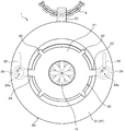
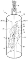
- Patent Document 1 a pendant top attached to a pendant chain is described. Is disclosed. Here, the pendant top of Patent Document 1 will be briefly described with reference to FIGS. 19 and 20.
- the pedestal portion 72 includes a pedestal main body portion 73 that holds a diamond (jewel) 71, left and right arm portions 74 that extend outward in the width direction from the left and right sides of the pedestal main body portion 73, and the tip of the arm portion 74. And left and right annular pedestal side engaging ring portions 75 arranged in the portion.
- the pedestal main body 73 is provided with a plurality of claw portions 76 for fixing the diamond 71.
- the left and right arm parts 74 and the pedestal side engagement ring part 75 are oriented so that the front and back directions of the ring part 75 are in a side view of the pendant top 70 with respect to the table surface of the diamond 71 held by the pedestal part 72. It is arranged so as to incline.
- Patent Document 1 when the front surface and the back surface of the pedestal-side engagement ring portion 75 are parallel to the direction of gravity (when the central opening of the pedestal-side engagement ring portion 75 faces in the horizontal direction), the pedestal portion 72.
- the table surface of the diamond 71 held on the surface is arranged so as to face obliquely upward.
- the pedestal portion 72 of Patent Document 1 is configured so that the pedestal top engaging ring portion 75 of the pendant top 70 is supported when the pedestal side engaging ring portion 75 is connected to a frame side engaging ring portion 82 described later of the frame portion 81 and supported by the frame portion 81.
- the position of the contact point at which the pedestal side engagement ring portion 75 contacts the frame side engagement ring portion 82 is arranged above the gravity center position of the diamond 71 and the pedestal portion 72 as a whole. It is formed as follows.
- the frame portion 81 of Patent Document 1 includes a frame main body portion 83 that has an inverted V shape when viewed from the front, and left and right frame-side engagement ring portions 82 provided on the back surfaces of the left and right lower end portions of the frame main body portion 83. . Further, a chain connecting hole 84 for connecting a pendant chain is provided at the upper end of the frame main body 83 so as to penetrate in the left-right direction (the width direction of the pendant top 70).
- the left and right frame side engagement ring portions 82 are formed integrally with the frame main body portion 83 so that the central opening of the frame side engagement ring portion 82 faces in the left and right direction when the pendant top 70 is suspended from the chain.
- the left and right frame-side engagement ring portions 82 are connected to and engaged with the left and right pedestal-side engagement ring portions 75 in the pedestal portion 72, respectively.
- the frame-side engagement ring portion 82 and the pedestal-side engagement ring portion 75 are engaged with each other so as to penetrate each other's central opening and bring the inner peripheral edges into contact with each other.
- the pedestal portion 72 has the inner peripheral edge portion of the left and right frame side engagement ring portions 82 in the frame portion 81, and the left and right pedestal side engagement ring portions 75 have the inner peripheral edge portion. It is held by the frame portion 81 so as to be brought into contact and caught. Accordingly, for example, when the pendant top 70 is moved or shaken, the pedestal 72 and the diamond 71 held by the pedestal 72 are slightly swung back and forth while being suspended from the frame 81. It becomes possible to make it. Thus, the diamond 71 can be shined more beautifully by swinging the diamond 71 small.
- the pedestal part 72 is supported by the frame part 81 so that the table surface of the diamond 71 faces obliquely upward.
- the diamond 71 can be made to shine more effectively by making the table surface of the diamond 71 easily enter the eyes of others at the chest of the user wearing the pendant.
- one or both of the pedestal side engagement ring portion 75 and the frame side engagement ring portion 82 has a shape in which a cross-sectional shape perpendicular to the circumferential direction becomes narrower toward the inner peripheral edge. It is described that it forms. Thereby, when the base side engagement ring part 75 and the frame side engagement ring part 82 are engaged, the contact area of both members can be reduced, and the frictional resistance when the base part 72 swings can be reduced. The time for which the diamond 71 swings can be extended longer.
- the pedestal portion 72 is supported by the frame portion 81 via the pedestal side engagement ring portion 75 and the frame side engagement ring portion 82.
- the diamond 71 held on the pedestal 72 can be rocked finely.
- the pedestal-side engagement ring portion 75 of the pedestal portion 72 includes the front (front side), the rear (back side), the upper side, the lower side, and the width direction (left and right) of the pendant top 70.
- the frame side engagement ring portion 82 of the frame portion 81 has its front (front) side covered with a frame main body portion 83, but is behind (back side), above and below the frame side engagement ring portion 82. And the outer side in the width direction are exposed.
- the pedestal side engaging ring part 75 and the frame side engaging ring part 82 exposed to the outside collide with or collide with another object (article).
- the base side engaging ring part 75 and the frame side engaging ring part 82 may receive an unexpected load (external force) locally, or may be strongly pressed and receive a large load.
- this pendant top 70 the structure in which the diamond 71 is swung by the pedestal side engagement ring portion 75 and the frame side engagement ring portion 82 is small and delicate, and is therefore susceptible to deformation. Is provided. Therefore, when the pedestal side engagement ring portion 75 and the frame side engagement ring portion 82 receive a force (external force) from the outside locally or strongly as described above, the pedestal side engagement ring portion 75 and the frame side engagement ring portion are engaged. Deformation such as distortion is likely to occur in the ring portion 82, and as a result, the above-described inconvenience that the fine swinging motion of the diamond 71 cannot be performed smoothly or becomes impossible, or the pedestal portion 72 is detached from the frame portion 81. There is a risk of malfunction.
- the pedestal side engagement ring portion 75 and the frame side engagement ring portion 82 of the pendant top 70 are exposed to the outside, the pedestal side engagement ring portion 75 and the frame side engagement ring portion 82 are used. It is conceivable that a person's hair, clothing, or a scarf such as a muffler may get entangled. In this way, if the yarn or the like is left entangled with the pedestal side engaging ring portion 75 or the frame side engaging ring portion 82, the fine swinging motion of the diamond 71 may be hindered.
- the pedestal side engagement ring portion 75 and the frame side engagement ring portion 82 are arranged so as to be exposed to the outside, the design of the pendant top 70 is restricted, and it is difficult to increase design variations.
- a specific object of the present invention is to directly apply external force to the pedestal-side engagement ring portion and the frame-side engagement ring portion that connect the pedestal portion and the frame portion.
- the object is to provide a garment that can stably maintain a state in which a jewel held on a pedestal is finely swingable over a long period of time.
- the ornament according to the first aspect of the present invention includes a pedestal portion for fixing and holding a jewel, and a frame portion for supporting the pedestal portion, and the pedestal portion is disposed at a position facing the jewel.
- a pair of left and right pedestal side engagement ring portions that are connected to and engaged with the left and right pedestal side engagement ring portions are fixed to the frame portion,
- the left and right pedestal side engagement ring portions are connected to the frame side engagement ring portion, respectively, so that the pedestal portion and the jewel are swingably supported in a state of being suspended from the frame portion.
- the left and right frame-side engagement ring portions and the left and right pedestal-side engagement ring portions in a state where the pedestal-side engagement ring portion and the frame-side engagement ring portion are connected to each other.
- the protection member that protects the connecting portion with respect to the frame side engagement ring portion from the outside, and the protection member includes the left and right frame side engagement ring portions and the connection portions of the left and right pedestal side engagement ring portions. Cover the front part of the front side of the frame so that it is not exposed, and cover the back side of the connecting parts of the left and right frame side engagement ring parts and the left and right base side engagement ring parts. It has a rear part that protects and is fixed to the front part.
- the ornament according to the second aspect of the present invention has a pedestal portion for fixing and holding a jewel, and a frame portion for supporting the pedestal portion, and the pedestal portion is arranged at a position facing the jewel.
- a pair of left and right pedestal side engagement ring portions that are connected to and engaged with the left and right pedestal side engagement ring portions are fixed to the frame portion,
- the left and right pedestal side engagement ring portions are connected to the frame side engagement ring portion, respectively, so that the pedestal portion and the jewel are swingably supported in a state of being suspended from the frame portion.
- the frame portion includes at least the left and right frame side engagement ring portions and the left and right pedestal sides in a state where the pedestal side engagement ring portion and the frame side engagement ring portion are connected to each other.
- a front part that covers and protects the front side of the coupling portion with the connecting portion to the frame side engagement ring portion so as not to be exposed, and the left and right frame side engagement ring portions and the left and right pedestal side engagement ring portions.
- a rear part that covers and protects the back side of the connecting part so as not to be exposed and is fixed to the front part; and at least the frame-side engagement ring part between the front part and the rear part And a housing chamber for housing the connecting portion of the pedestal side engaging ring portion inside and protecting it from the outside.
- the portion that connects the pedestal portion that fixes and holds the gemstone and the frame portion that supports the pedestal portion from receiving external force directly, and the gemstone held on the pedestal portion can be finely swung.
- the jewelry which can be maintained stably over a long period of time can be provided.
- FIG. 1 It is a front view which shows the pendant top which concerns on Example 1 of this invention. It is a rear view of a pendant top. It is a side view of a pendant top. It is a schematic diagram when the base part distribute
- FIG. 6 is a cross-sectional view showing a frame part (protective member) of a pendant top according to a modification of Example 1.
- 6 is a front view showing a pendant top according to another modification of Example 1.
- FIG. FIG. 10 is a front view showing a pendant top according to still another modified example of the first embodiment. It is a front view which shows the pendant top which concerns on Example 2 of this invention. It is a side view of a pendant top. It is a front view which shows the pendant top which concerns on Example 3 of this invention. It is a side view of a pendant top. It is an enlarged schematic diagram when the part by which the protection member is being fixed to the frame part of the pendant top is seen from the inner side of the width direction.
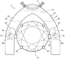
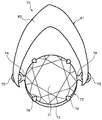
- FIG. 1 is a front view illustrating the pendant top according to the first embodiment.
- 2 and 3 are a rear view and a side view of the pendant top.
- three directions orthogonal to each other in the accessory (pendant) are defined as a vertical direction, a width direction (also referred to as a horizontal direction), and a front-back direction. That is, the direction in which a pair of pedestal side engagement ring portions 24 are arranged with respect to the gemstone 10 described later is the width direction, and the front side and the back side of the gemstone 10 (for example, the table surface of the gemstone 10 and the culet portion 11) are mainly oriented.
- the direction is the front-rear direction, and the direction perpendicular to the width direction and the front-rear direction is the up-down direction.
- the up-down direction and the left-right direction are the up-down direction and the left-right direction when the pendant top is attached to the pendant chain and lifted, and the front-rear direction is the front of the pendant top when the pendant is worn.
- the pendant top 1 according to the first embodiment is attached to a string-like member such as a chain 5 to form a pendant (or necklace) as an ornament.
- the pendant top 1 according to the first embodiment includes a pedestal portion 20 that fixes and holds diamond as a jewel 10, and a frame portion 30 that supports the pedestal portion 20 and the jewel (diamond) 10 so as to be swingable.
- a part of the frame portion 30 of the first embodiment (a frame main body portion 31 described later) is also formed as a protective member as described below.
- the jewel 10 held on the pedestal 20 may be a natural gem (natural mineral) such as sapphire other than diamond, a synthetic gem (artificial gem) using a synthesized mineral, or a counterfeit gem using glass or the like. Etc.
- the pedestal 20 and the jewel 10 are supported so as to be swingable while being suspended from the frame 30 so that the front side (for example, the table surface) of the jewel 10 can be seen from the front.
- the pedestal portion 20 of the first embodiment includes a pedestal main body portion 21 on which the jewel 10 is placed, and a plurality of claw portions 22 that protrude from the pedestal main body portion 21 and fix the jewel 10.
- the left and right arm portions 23 extending from the left and right side edge portions (side end portions) of the pedestal main body portion 21 toward the outer side in the width direction of the pedestal portion 20, and the distal ends of the left and right arm portions 23.
- the left and right pedestal side engagement ring portions 24 are arranged at positions opposite to each other across the jewel 10.
- the pedestal portion 20 of the first embodiment is integrally formed as a single member by performing press processing (press punching processing) or the like on a plate made of noble metal such as gold, platinum, or silver.
- the material and production method of the base part 20 are not specifically limited.
- the shapes of the pedestal main body 21 and the claw portions 22 and the number of the claw portions 22 disposed are not limited and can be arbitrarily changed.
- a circular opening 21 a is formed at the center of the pedestal main body 21, and the jewel 10 protrudes from the opening 21 a of the pedestal main body 21 rearward and is fixedly held on the pedestal 20.
- the left and right arm portions 23 in the pedestal portion 20 are portions that connect the pedestal main body portion 21 and the left and right pedestal side engagement ring portions 24.
- the left and right arm portions 23 have symmetrical shapes with each other, extend from the pedestal main body portion 21 to the outside in the left-right direction, and are inclined to the front.
- the left and right arm portions 23 can be changed in length according to the design of the pendant top 1 and the pedestal portion 20 is formed without providing the left and right arm portions 23 if necessary. It is also possible to do.
- the left and right pedestal side engagement ring portions 24 in the pedestal portion 20 are formed in an annular shape, and a circular central opening 24a is provided at the center thereof.
- the left and right pedestal side engagement ring portions 24 are provided at positions corresponding to each other on the left and right sides of the pedestal main body portion 21.
- the jewel 10 is disposed between the left and right pedestal side engagement ring portions 24.
- the left and right pedestal side engagement ring portions 24 are integrally formed with the pedestal main body portion 21 via the left and right arm portions 23.
- the left and right pedestal side engagement ring portions 24 may be formed as separate members from the pedestal main body portion 21 and connected via the left and right arm portions 23.
- the pedestal side engagement ring portion 24 is formed so that the cross-sectional shape orthogonal to the circumferential direction of the pedestal side engagement ring portion 24 exhibits an irregular cross-sectional shape that is not circular.
- the pedestal side engagement ring portion 24 of the first embodiment shown in FIG. 6 is formed so that the tip on the inner peripheral side of the pedestal side engagement ring portion 24 is pointed.
- the pedestal side engagement ring portion 24 has a tapered shape in which the shape of the cross section perpendicular to the circumferential direction becomes gradually narrower toward the inner peripheral edge.
- the base side engaging ring part 24 when the base side engaging ring part 24 is connected to the frame side engaging ring part 32 of the frame part 30, the base side engaging ring part 24 and the frame side engaging ring part 32 cross each other and contact each other.
- the contact area of the pedestal side engagement ring portion 24 in the contact portion O to be reduced can be reduced.
- the frictional resistance of the pedestal side engagement ring portion 24 against the frame side engagement ring portion 32 can be suppressed to a low level.
- 20 and the jewel 10 can be swung finely and smoothly with respect to the frame portion 30.
- the rocking motion of the pedestal 20 and the jewel 10 can be continued for a relatively long time without stopping, and the rocking time can be extended longer.
- the cross-sectional shape of the pedestal side engagement ring portion 24 is not limited to the example of FIG. 6, and the cross section of the pedestal side engagement ring portion 24 is formed in a circular shape or other shapes. It is also possible to do.
- the pedestal portion 20 of the first embodiment is configured so that the jewel 10 and the pedestal portion 20 are supported by the frame portion 30 via the pedestal side engagement ring portion 24 and the frame side engagement ring portion 32, and the table surface of the jewel 10 is. And the position of the contact portion O between the pedestal side engaging ring portion 24 and the frame side engaging ring portion 32 in the side view of the pendant top 1 is the position of the center of gravity of the pedestal portion 20 and the jewel 10 as a whole.
- the position and orientation of the pedestal-side engagement ring portion 24 with respect to the pedestal main body portion 21 are set so as to be disposed above the pedestal. At this time, the pedestal portion 20 is supported by the frame portion 30 in a posture in which the central opening 24a of the pedestal side engagement ring portion 24 faces in the front-rear direction.
- the entire pedestal 20 and the jewel 10 are seen in the side view of the pendant top 1.
- the pedestal portion 20 is formed such that the center of gravity is disposed on the back side (rear side) with respect to the position of the contact portion O between the pedestal side engagement ring portion 24 and the frame side engagement ring portion 32.
- the left and right pedestal side engagement ring portions 24 are held so that the central opening 24a faces obliquely downward when the jewel 10 is directed to the front so that the table surface of the jewel 10 is parallel to the vertical direction.
- the table surface of the jewel 10 is obliquely upward when the jewel 10 and the pedestal 20 are suspended from the frame 30 held along the direction of gravity. It is preferable that the pedestal 20 is formed so as to be inclined. In this case, the pedestal 20 is formed so that the inclination angle ⁇ of the table surface of the jewel 10 with respect to the direction of gravity is an angle of 5 ° to 45 °, preferably an angle of 10 ° to 20 °.
- the frame portion 30 of the first embodiment includes a frame main body portion 31 provided as a protection member, left and right frame-side engagement ring portions 32 fixed to the inner surface of the frame main body portion 31, and a frame It has a chain connecting portion 33 (annular clasp) that is provided at the upper end portion of the main body portion 31 so as to protrude upward and is connected to the pendant chain 5.
- the chain connecting portion 33 is fixed to the frame main body portion 31 by brazing (welding) with a laser or the like, for example.
- the frame main body 31 of the first embodiment has a donut shape that surrounds the pedestal 20 and the jewel 10 from the outside in a front view of the pendant top 1.
- the frame main body 31 is spaced outward from the jewel 10 held by the pedestal 20 in the front view of the pendant top 1 so that the pedestal 20 and the jewel 10 do not come into contact with each other.
- a gap is formed between the frame body portion 31 and the frame body portion 31.
- the frame main body 31 has a front and back symmetrical shape that exhibits the same donut shape when viewed from the front side and the back side.
- the frame body portion 31 of the first embodiment has a back-side front end portion (that is, the curette portion 11) arranged on the most back side of the jewelry 10 in the side view of the pendant top 1. It has a thickness in the front-rear direction so as to be located on the front surface side of the back surface position of the main body portion 31.
- the back surface of the frame main body portion 31 is arranged at a position on the back side with respect to the front and back direction of the pendant top 1 with respect to the position of the curette portion 11 of the jewel 10.
- the jewel 10 is stably placed at a position away from the clothing or the like on the surface side of the pendant top 1. Can be held. For this reason, it can prevent effectively that the fine rocking
- FIG. 5 is a cross-sectional view of the center portion in the left-right direction of the frame main body 31 taken along a plane orthogonal to the left-right direction.
- the frame main body 31 of the first embodiment is formed with a predetermined thickness.
- the frame main body 31 has an appropriate strength.
- the frame main body 31 of the first embodiment has a hollow shape in which an internal space (accommodating chamber) 34 is formed in the frame main body 31.
- the frame main body 31 is a part that constitutes a part of the frame part 30 and is also a protective member that surrounds and protects the frame side engagement ring part 32 and the base side engagement ring part 24 from the outside.
- the protective member that protects the frame-side engagement ring portion 32 and the pedestal-side engagement ring portion 24 is formed as the frame main body portion 31 that supports the pedestal portion 20 and the jewel 10.
- the frame main body (protective member) 31 includes one frame-side engagement ring portion 32 and a base-side engagement ring portion 24 that are mutually connected on the left side, and the other that is mutually connected on the right side.
- the frame side engagement ring part 32 and the base side engagement ring part 24 are formed as a single member capable of protecting the frame side engagement ring part 32 and the base side engagement ring part 24 at the same time.
- the internal space 34 of the frame main body (protective member) 31 can be accommodated in a state where the left and right frame side engagement ring portions 32 and the pedestal side engagement ring portion 24 are engaged with each other.
- the frame-side engagement ring portion 32 and the base-side engagement ring portion 24 have a size that does not interfere (do not collide) even when the portion 20 and the jewel 10 swing.
- the internal space 34 of the frame main body portion (protective member) 31 is a storage chamber that accommodates the pair of left and right frame side engagement ring portions 32 and the pedestal side engagement ring portion 24 in a mutually engaged state. It is formed as.
- the frame body portion (protective member) 31 of the first embodiment includes left and right annular frame side engagement ring portions 32 fixed to the inner surface of the frame body portion 31 and left and right annular body portions provided on the pedestal body portion 21. In a state where the pedestal side engaging ring portion 24 is connected to each other, these engaging ring portions 32 and 24 are arranged in the internal space 34 (accommodating chamber) and accommodated inside the frame main body portion (protective member) 31. To do. Thereby, the frame main body part (protective member) 31 has at least the front surface (front surface), the back surface (rear surface), the upper surface, the lower surface, and the width of the frame side engagement ring portion 32 and the base side engagement ring portion 24 in the connected state. The outer side surface of the direction is continuously covered from the outside so as not to be exposed, and the frame side engaging ring part 32 and the base side engaging ring part 24 are protected as a whole.
- the frame main body 31 of the first embodiment has a constant shape in which a cross section orthogonal to the circumferential direction has a substantially C-shape that is long in the front-rear direction in the entire circumference.
- an inner peripheral side gap 35 that opens toward the pedestal 20 and the jewel 10 is formed at the inner peripheral edge of the frame main body 31.
- the inner circumferential gap 35 is formed on the inner peripheral edge of the ring-shaped frame main body 31 over the entire circumferential direction of the frame main body 31 (over the entire circumference).
- a part of the inner circumferential side gap 35 of the frame main body portion 31 serves as an insertion opening through which the left and right arm portions 23 of the pedestal portion 20 are inserted.
- the frame-side engagement ring portion 32 is fixed in a state of being in contact with a part of the curved inner surface of the frame main body portion 31.
- the left and right arm portions 23 only in a predetermined range in which the swinging of the pedestal portion 20 and the jewel 10 is ensured, such as the inner peripheral side gap 35b of the frame main body portion 31b shown as a modified example in FIG. May be formed so as to open toward the pedestal 20 and the jewel 10.
- the inner circumferential side gap 35 of the frame main body 31 is such that, in normal use of the pendant, the pedestal 20 and the jewel 10 swing with respect to the frame 30 in an angle range of about 20 ° in the front-rear direction (ie, 3) Even if the pedestal 20 and the jewel 10 are swung in an angle range of about 10 ° from the state of FIG. 3 toward the front and the rear, respectively, the left and right arm portions 23 hardly interfere (or do not interfere). It is formed with a size (interval).
- the inner circumferential side gap 35 of the frame main body portion 31 regulates the swing range of the pedestal portion 20 and the jewel 10 so that the pedestal portion 20 and the jewel 10 swing appropriately at a predetermined angle with respect to the frame portion 30. It is formed in size. That is, when the swing of the pedestal part 20 and the jewel 10 becomes larger than a certain degree, the pedestal part 20 and the jewel 10 come into contact with the frame main body part 31 (a front part 36 or a rear part 37 to be described later). And the rocking
- the inner peripheral side gap 35 of the frame main body 31 is provided such that the center position in the front-rear direction of the inner peripheral side gap 35 coincides with the center position in the front-rear direction of the frame main body 31.
- the inner circumferential gap 35 is provided such that the center position in the front-rear direction of the inner circumferential gap 35 is shifted forward or rearward with respect to the center position in the front-rear direction of the frame body 31. May be.
- the donut-shaped frame main body 31 of the first embodiment includes a front part 36 that covers and protects the front side of the frame side engagement ring portion 32 and the base side engagement ring portion 24 so as not to be exposed, and frame side engagement.
- a rear part 37 that covers and protects the ring part 32 and the back side of the pedestal side engagement ring part 24 so as not to be exposed.
- the front part 36 and the rear part 37 of the frame main body 31 have symmetrical shapes.
- Such a front part 36 and a rear part 37 are fixed to each other by brazing using a laser or the like, for example.
- the means for fixing the front part 36 and the rear part 37 to each other is not particularly limited.
- the front part 36 and the rear part 37 of the frame main body 31 are subjected to press processing (press punching processing) on a precious metal plate material such as gold, platinum, silver, etc., for example, 0.5 mm. It is manufactured to have a thickness of the following (preferably 0.1 mm or less).
- the left and right pedestal side engaging ring parts 24 are connected to the left and right frame side engaging ring parts 32.
- the front part 36 and the rear part 37 are combined and fixed so as to wrap the connected left and right frame side engagement ring portions 32 and the pedestal side engagement ring portion 24. Therefore, the frame main body 31 can be easily assembled, and the left and right frame side engagement ring portions 32 and the pedestal side engagement ring portion 24 can be assembled in the frame main body portion (protective member) 31. In particular, it can be stably accommodated in the above-described accommodation chamber (internal space 34) of the frame main body 31.
- the front part 36 and the rear part 37 have symmetrical shapes, the same parts having a fixed donut shape can be used as the front part 36 and the rear part 37. Thereby, the front part 36 and the rear part 37 can be produced at low cost. Further, since the front part 36 and the rear part 37 are not mistaken, the work of fixing the front part 36 and the rear part 37 in combination can be prevented and the work efficiency can be improved.
- the shape and material of the front part 36 and the rear part 37 of the frame main body 31 serving as a protective member are not limited to the shape and material of the first embodiment.
- the shape and material of the first embodiment For example, in the second embodiment described later. As will be described, any change is possible.
- the left and right frame side engagement ring portions 32 in the first embodiment are formed by cutting a metal linear member having a circular cross section into a predetermined length and bending the cut linear member into a ring shape.
- the frame-side engagement ring portion 32 before the pedestal-side engagement ring portion 24 is connected has a round can shape having a gap into which the pedestal-side engagement ring portion 24 can be inserted.
- the left and right annular pedestal side engagement ring portions 24 can be easily connected and engaged with the left and right frame side engagement ring portions 32, respectively.
- the base side engaging ring part 24 and the frame side engaging ring part 32 are joined together so that the inner peripheral edge parts are in contact with each other.
- the abutted ends of the frame side engagement ring portion 32 are brazed or the like as necessary. It is also possible to fix.
- the frame-side engagement ring portion 32 of the first embodiment is formed so that the cross-sectional shape orthogonal to the circumferential direction has a circular shape.
- the cross-sectional shape of the frame-side engagement ring portion 32 is not particularly limited, and the cross-sectional shape of the frame-side engagement ring portion 32 is, for example, a pedestal-side engagement ring portion 24 shown in FIG. It is also possible to adopt a tapered shape or other shapes.
- the left and right frame-side engagement ring portions 32 of the first embodiment are arranged at predetermined positions on the inner surface (inner wall surface) of the front part 36 of the frame main body 31, and the central opening of the frame-side engagement ring portion 32 is in the left-right direction.
- the pendant top 1 is fixed by brazing with a laser or the like in a posture parallel to the vertical direction when viewed from the front (FIG. 1). Since the left and right frame side engagement ring portions 32 are fixed to the front part 36 of the frame main body portion 31, the pedestal portion 20 and the jewelry 10 can be stably held at a position on the front side of the pendant top 1.
- the jewel 10 can be made more conspicuous.
- means for fixing the frame side engagement ring portion 32 to the frame main body portion 31 is not limited, and fixing means other than brazing can be adopted.
- the frame side engagement ring portion 32 of the first embodiment is fixed to the frame main body portion 31 in a posture parallel to the vertical direction as described above, but in the present invention, the frame fixed to the frame main body portion 31 is used.
- the direction and orientation of the side engagement ring portion 32 are not particularly limited.
- the frame side engaging ring portion 32c is fixed to the frame main body portion 31 in a posture inclined with respect to the vertical direction. It is also possible.
- the frame-side engagement ring portion 32 of the first embodiment is formed as a separate member from the frame main body portion 31 and is fixed to the frame main body portion 31 using a fixing means. It is also possible to integrally form the engagement ring portion 32 and the frame main body portion 31 as a single member.
- the left and right frame side engagement ring portions 32 may be fixed to the inner surface of the rear part 37 instead of the front part 36 of the frame main body 31. Further, for example, the size of the frame side engagement ring portion 32 is increased, and the frame side engagement ring portion 32 is fixed to the inner surfaces of both the front part 36 and the rear part 37, or for example, the frame side engagement ring portion 32. It is also possible to adjust the fixed position with respect to the front part 36 by providing a fixed piece adjusting protrusion piece or the like. Further, the operation of connecting the pedestal side engaging ring portion 24 to the frame side engaging ring portion 32 as described above is performed after the frame side engaging ring portion 32 is fixed to the frame main body portion 31 (the front part 36 and the rear part). 37 may be performed before the frame side engagement ring portion 32 is fixed to the frame main body portion 31.
- the pedestal portion 20 is a frame.
- the part 30 is supported via a pedestal side engaging ring part 24 and a frame side engaging ring part 32.
- the pedestal 20 In addition, the jewel 10 can be swayed and moved continuously in a small direction in the front-rear direction while being suspended from the frame portion 30. Thereby, a diamond can be made to shine more beautifully.
- the pedestal portion 20 and the jewelry 10 swing slightly in the front-rear direction around the position of the contact portion O between the pedestal side engagement ring portion 24 and the frame side engagement ring portion 32. . Further, when the pedestal portion 20 and the jewel 10 swing, the position of the contact portion O may also move back and forth along the inner peripheral edge of the frame side engagement ring portion 32.
- the pedestal 20 and the jewel 10 are swung at substantially the center of the circular central opening formed in the frame 30.
- the frame part 30 having a simple donut-like shape looks clean and beautiful.
- the jewel 10 appears to be floating in the air with respect to the frame portion 30, the swing of the pedestal portion 20 and the jewel 10 can be effectively shown to stand out with respect to the surrounding frame portion 30. it can. Accordingly, the shine of the jewel 10 fixed to the pedestal portion 20 can be made more beautiful, and an unprecedented image (aesthetics) can be given to the pendant top 1.
- the pedestal 20 and the jewel 10 can be swung to prevent the pedestal 20 and the jewel 10 from coming into direct contact with clothes or mufflers worn by the user 6 when the pendant is used. Stable state is ensured.
- the back surface disposed on the most back surface side of the frame main body portion 31 is located further rearward (back side) than the curette portion 11 of the jewel 10.
- the curette part 11 of the jewel 10 does not protrude further rearward than the back surface of the frame main body part 31 not only in the state shown in FIG. 3 but also in the state shown in FIG.
- the pedestal 20 and the jewel 10 are held at a position distant from the surface side of the pendant top 1 from clothes or a muffler worn by the user 6. For this reason, when the pedestal 20 and the jewel 10 swing within the swing range of the inner circumferential side gap 35 of the frame main body 31, the pedestal 20 and the jewel 10 are slightly swung to clothes, a muffler, and the like. It is possible to effectively prevent the pedestal 20 and the jewel 10 from swinging stably.
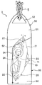
- the frame main body 31 is held along the vertical direction as shown in FIG. 3, for example, the frame main body 31 is provided at the chest of the user 6 as shown in FIG.
- the jewel 10 is held slightly inclined with respect to the vertical direction
- the jewel 10 and the pedestal 20 are supported by the frame 30 so that the table surface of the jewel 10 faces obliquely upward.
- the pendant top 1 of the first embodiment can make the jewel 10 shine more effectively at the chest of the user 6 wearing the pendant so that the table surface of the jewel 10 can easily enter the eyes of others. it can.
- the left and right frame side engagement ring portions 32 and the pedestal side engagement ring portion 24 are small and delicately formed, so that they have a property of being weak against deformation.
- the left and right frame-side engagement ring portions 32 and the left and right pedestal-side engagement ring portions 24 are all covered and protected by the frame main body portion 31 serving as a protection member (in other words, All of the left and right frame side engagement ring portions 32 and all of the left and right pedestal side engagement ring portions 24 are accommodated and protected in the accommodation chamber (internal space 34) of the frame main body 31).
- the pedestal-side engagement ring portion 24 and the frame-side engagement ring portion 32 are not exposed to the outside, so that the pedestal-side engagement ring portion 24 and the frame-side engagement ring portion 32 are not exposed to normal use as a pendant. It is possible to prevent a direct collision with another object or an accidental direct strong press.
- the pedestal side engagement ring portion 24 and the frame side engagement ring portion 32 do not directly receive an unintended external force (load) from the outside. As a result, it is possible to effectively prevent the base side engagement ring portion 24 and the frame side engagement ring portion 32 from being deformed or damaged. Therefore, the state in which the jewel 10 can swing finely and smoothly can be stably maintained over a long period of time.
- the pedestal side engagement ring portion 24 and the frame side engagement ring portion 32 are protected by the frame main body portion (protective member) 31, so that hair, thread, and the like can be attached to the pedestal side engagement ring portion 24 and the frame side engagement. It is also possible to prevent entanglement with the mating ring portion 32. Thereby, the handleability of the pendant can be improved, and it is also possible to prevent the minute rocking of the jewel 10 from being hindered by the entanglement of the thread or the like.
- the pedestal side engagement ring portion 24 and the frame side engagement ring portion 32 are covered with the frame main body portion 31 and cannot be seen from the outside, so that the frame quality of the pendant top 1 is not impaired. It is also possible to make the side engagement ring portion 32 thicker. Thereby, it is possible to increase the fixing strength of the frame side engagement ring portion 32 with respect to the frame main body portion 31, increase the durability of the pendant top 1, and the like.
- the pedestal side engagement ring portion 24 and the frame side engagement ring portion 32 are covered and hidden by the protective member (frame main body portion 31), and are covered and protected.
- the protective member is formed as a noble metal frame main body 31 of the frame portion 30. This improves the overall texture of the pendant top 1 and improves the appearance quality, despite the fact that a member for protecting the ring portion that was not present in the conventional pendant top is newly provided in the first embodiment. Can be increased.
- the frame main body 31 serving as a protective member is formed in a hollow shape with a reduced thickness as described above, the amount of raw materials used for the frame main body 31 is reduced, and the frame The manufacturing cost of the part 30 can be significantly reduced. In particular, in the case of the first embodiment, for example, the manufacturing cost of the frame main body 31 can be reduced to less than half compared to the case where the frame main body is formed solid.
- the pedestal side engagement ring portion 24 and the frame side engagement ring portion 32 are covered with the frame main body portion (protective member) 31, the pedestal side engagement ring portion 24 and the frame side engagement ring portion 32 It is possible to reduce the influence of the presence on the design of the pendant top 1 and increase the degree of freedom of design. Further, various designs can be adopted for the frame main body portion (protective member) 31.
- the frame main body (protective member) can be formed in a heart-shaped frame shape like the frame main body (protective member) 31a in the pendant top 1a of the modification shown in FIG. 9, for example.
- the size and thickness of the frame main body (protective member), the size of the frame-side engagement ring portion, and the like can be arbitrarily changed.
- the pendant top 1a of FIG. 9 is formed in the same manner as the pendant top 1 of Example 1 described above, except for the shape of the frame main body (protective member) 31a.
- the part or member which has the same structure as the above-mentioned Example 1 is represented using the same code
- the entire frame main body 31 that serves as a protection member includes the entire left and right frame side engagement ring portions 32 of the frame portion 30 and the entire left and right pedestal side engagement ring portions 24 of the pedestal portion 20. It is covered and protected by.
- at least the entire left and right frame-side engagement ring portions 32 of the frame portion 30 and the connecting portion between the left and right pedestal-side engagement ring portions 24 and the frame-side engagement ring portion 32 are the frame body. What is necessary is just to be protected by the part 31.
- the connecting portion of the pedestal side engaging ring portion 24 with the frame side engaging ring portion 32 is an arc-shaped portion of the pedestal side engaging ring portion 24 that is connected to and in contact with the frame side engaging ring portion 32.
- This connecting portion includes a range (region) in which the inner peripheral edge of the frame-side engagement ring portion 32 is in sliding contact when the jewel 10 is slightly swung.
- the pedestal side engagement ring part 24 is connected to the frame side engagement ring part 32 by connecting the arc-shaped part of the pedestal side engagement ring part 24 to the inner peripheral edge of the frame side engagement ring part 32. It has a connecting part that is in sliding contact.
- the left and right pedestal side engagement ring portions 24c are formed larger than the first embodiment, and the left and right pedestal side engagement ring portions 24c A portion of the ring other than the portion connected to the frame side engagement ring portion 32c is exposed. At the same time, the entire frame-side engagement ring portion 32 c and at least the connecting portion of the base-side engagement ring portion 24 c are covered and protected by the frame body portion 31.
- the base side engagement ring portion 24c and the frame side engagement ring portion 32c can be deformed or damaged due to an unintended external force (load).
- the minute swingable state of the jewel 10 can be stably maintained over a long period of time.
- hair, thread, and the like can be prevented from being entangled with the pedestal side engaging ring portion 24c and the frame side engaging ring portion 32c.
- FIG. 11 is a front view illustrating the pendant top according to the second embodiment.
- FIG. 12 is a side view of the pendant top.
- the pendant top 2 according to the second embodiment includes a pedestal portion 20 on which a jewel (diamond) 10 is fixed and held, and a frame portion 40 that supports the pedestal portion 20 and the jewel (diamond) 10 and is formed as a protective member.
- the pendant top 2 according to the second embodiment is different from the pendant top 1 according to the first embodiment described above in, for example, the form of the frame portion 40, but the pedestal portion 20 and the jewelry 10 are different from the pendant top 1 according to the first embodiment described above. It is formed similarly to the case of. Accordingly, in the description and drawings related to the second embodiment, and further in the description and drawings related to the third and fourth embodiments described later, the parts or members having substantially the same configuration as the pendant top 1 of the first embodiment described above. Are denoted by the same reference numerals, and detailed description thereof will be omitted.
- the frame part 40 of the second embodiment is arranged so as to surround the pedestal part 20 and the jewel 10 in the front view of the pendant top 2, and is provided with a frame main body part 41 provided as a protective member, and the frame main body part 41 It has left and right frame-side engagement ring portions 42 fixed to the inner surface, and a chain connecting portion 43 provided to protrude upward at the upper end portion of the frame main body portion 41.
- the chain connecting portion 43 forms a small mounting hole (not shown) in the frame main body portion 41 (particularly the rear part 47 of the frame main body portion 41), and inserts and fixes a fastener (not shown) of the chain connecting portion 43 into the mounting hole. By doing so, it is attached to the frame main body 41.
- the method and means for attaching the chain connecting portion 43 to the frame main body portion 41 are not particularly limited.
- the frame body 41 of the second embodiment has a donut shape that surrounds the entire base 20 and the jewel 10 from the outside in the front view of the pendant top 2.
- the frame body 41 is spaced outward from the pedestal 20 and the jewel 10 in a front view of the pendant top 2 so that the pedestal 20 and the jewel 10 do not come into contact with each other.
- a gap is formed between the terminal 41 and the terminal 41.
- the frame body 41 includes a front part 46 that covers and protects the front side of the frame side engagement ring portion 42 and the base side engagement ring portion 24 so as not to be exposed, and the frame side engagement ring portion 42 and the base side engagement. And a rear part 47 that covers and protects the rear side of the coupling portion 24 so as not to be exposed.
- the front part 46 of the frame main body 41 has substantially the same shape as the front part 36 of the frame main body 31 used in the first embodiment, and is smaller in size than the front part 36 as a whole. Is formed.
- the left and right frame-side engagement ring portions 42 are formed in a ring shape that is smaller in size than the frame-side engagement ring portion 32 used in the first embodiment.
- the rear part 47 of the second embodiment does not have a front / back symmetrical shape as in the first embodiment described above with respect to the front part 46, but is formed of a ceramic member having a donut shape. Yes.
- a circular central opening penetrating in the front-back direction is provided in the central portion of the rear part 47 of the second embodiment in front view.
- the inner diameter of the rear part 47 (the diameter of the central opening of the rear part 47) is set smaller than the outer diameter of the front part 46, and the pedestal The size is set such that the back side of the side engagement ring portion 24 and the frame side engagement ring portion 42 can be protected.
- the rear part 47 is fixed to the front part 46 by brazing using laser or the like or other fixing means.
- the shapes of the front part 46 and the rear part 47 can be arbitrarily changed.
- the rear part 47 it is possible to use a ceramic member that is not provided with a circular central opening.
- the rear part according to the modified example is arranged so that the central opening is closed at the position of the rear side end part of the rear part and at the position where it does not interfere with the pedestal part 20 and the jewel 10 that swing back and forth.
- the rear wall portion is formed integrally.
- the left and right frame side engagement ring portions 42 and the pedestal side engagement ring portion 24 are engaged with each other between the front part 46 and the rear part 47. It has a hollow shape in which an internal space that can be accommodated is formed. Therefore, the frame main body 41 is a part that constitutes a part of the frame part 40 and is also a protective member that surrounds and protects the frame side engagement ring part 42 and the base side engagement ring part 24 from the outside. .
- the internal space of the frame main body portion (protective member) 41 connects the frame side engagement ring portion 42 and the base side engagement ring portion 24 to each other. It is formed as a storage chamber that is housed inside in a state of being engaged with each other.
- the frame body part (protective member) 41 of the second embodiment includes left and right annular frame side engagement ring parts 42 fixed to the inner surface of the frame body part 41 and left and right annular body parts provided on the base body part 21. With the pedestal side engaging ring portion 24 connected to each other, these engaging ring portions 42 and 24 are arranged in the above-described accommodation chamber and accommodated inside the frame main body portion (protective member) 41. Thereby, the frame main body part (protective member) 41 has at least the front surface (front surface), the back surface (rear surface), the upper surface, the lower surface, and the width of the frame side engagement ring portion 42 and the pedestal side engagement ring portion 24 in the connected state. The outer side surface in the direction is continuously covered from the outside so as not to be exposed, so that the frame side engagement ring part 42 and the base side engagement ring part 24 are entirely protected.
- the frame main body portion (protective member) 41 includes the above-described accommodation of the frame main body portion 41 in a state where the frame-side engagement ring portion 42 and the pedestal-side engagement ring portion 24 in a connected state are connected.
- these engagement ring portions 42 and 24 are protected so as to cover at least the front (front) side, the back (rear) side, the upper surface, the lower surface, and the outer side in the width direction. be able to.
- an inner peripheral side gap (insertion opening) through which the left and right arm parts 23 of the pedestal part 20 are inserted is formed between the front part 46 and the rear part 47 at the inner peripheral edge of the frame body part 41. Yes.
- the left and right frame side engagement ring portions 42 of the second embodiment are formed in the same manner as in the first embodiment, and the laser is disposed at a predetermined position on the inner surface of the front part 46 of the frame main body portion 41. It is fixed by brazing with etc.
- the shape and material of the frame main body 41 serving as a protective member is different from the pendant top 1 of the first embodiment, but the jewel 10 can be finely and smoothly swung. Can be stably maintained over a long period of time, and the same effect as in the case of the above-described first embodiment can be obtained in which the fine rocking of the diamond can be prevented from being hindered by the entanglement of the yarn or the like.
- FIG. 13 is a front view showing the pendant top according to the third embodiment.
- FIG. 14 is a side view of the pendant top.
- FIG. 15 is an enlarged view showing a state in which the protective member is fixed to the frame portion of the pendant top.
- the pendant top 3 includes a pedestal portion 20 on which a jewel (diamond) 10 is fixed and held, and a pedestal portion 20 and a frame portion 50 that supports the jewel (diamond) 10.
- the frame unit 50 includes a frame main body 51 that has an inverted V shape in a front view of the pendant top 3 and left and right frame-side engagement ring units provided on the back surfaces of the left and right lower ends of the frame main body 51. 52 and a pair of left and right protective members 60 fixed to the back side of the left and right lower ends of the frame main body 51.
- the frame main body 51 and the protective member 60 are formed separately, and the protective member 60 itself is not directly formed as a member that supports the pedestal 20 and the jewel 10 (functions). Not) On the other hand, the pedestal 20 and the jewel 10 are formed in the same manner as in the case of the pendant top 1 of the first embodiment.
- a chain connecting hole 53 for connecting the pendant chain 5 is provided at the upper end of the frame main body part 51 so as to penetrate in the left-right direction. Further, the left and right lower end portions of the frame main body portion 51 are formed to extend further downward than the lower end positions of the pedestal portion 20 and the jewel 10 in the front view of the pendant top 3. By forming the left and right lower end portions of the frame main body 51 in this way, when the pendant top 3 of the third embodiment is worn, clothes or the like worn by the user are displayed below the pendant top 3. It can be made difficult to contact the jewel 10 and the base 20 from the side.
- left and right ring accommodating portions 54 for accommodating the frame side engaging ring portions 52 are provided on the back surfaces (back surfaces) of the left and right lower end portions.
- the ring housing portion 54 is formed by partially reducing the thickness of the frame body portion 51 in the front and back direction.
- Frame-side engagement ring portions 52 are integrally formed on the rear surfaces of the left and right ring housing portions 54, respectively.
- the frame side engagement ring portion 52 may be formed separately from the frame main body portion 51 and then fixed to a predetermined position of the frame main body portion 51 by brazing or the like.
- the left and right protective members 60 of Example 3 are formed as separate bodies.
- the left and right protection members 60 are brazed to the left and right lower ends of the frame main body 51 so as to cover the frame-side engagement ring portion 52 and the base-side engagement ring portion 24 in the connected state from the outside. It is fixed by.
- Each protection member 60 includes a rear wall portion 61 that covers the back side of the frame side engagement ring portion 52 and the pedestal side engagement ring portion 24, and the horizontal direction of the frame side engagement ring portion 52 and the pedestal side engagement ring portion 24.
- the outer side wall 62 covers the outer side and the bottom wall 63 covers the lower side of the frame side engagement ring 52 and the base side engagement ring 24.
- Inner side gaps (insertion openings) through which the left and right arm portions 23 of the pedestal portion 20 are inserted are formed on the inner side surfaces of the left and right lower end portions of the frame portion 50, and the left and right lower end portions of the frame main body portion 51 and the protective member 60. Between.
- the front side and the upper side of the frame-side engagement ring portion 52 and the pedestal-side engagement ring portion 24 in the connected state are connected to the frame main body portion 51 (front parts).
- the frame side engagement ring portion 52 and the base side engagement ring portion 24 in the connected state are protected by the protection member 60 (rear parts). Covered and protected.
- the internal space formed so as to be sandwiched between the left and right lower end portions of the frame main body portion 51 (front part) and the protective member 60 (rear part) is a frame.
- the side engagement ring portion 52 and the pedestal side engagement ring portion 24 are formed as a storage chamber that is housed and protected in the state of being engaged with each other.
- the state in which the jewel 10 can be finely and smoothly rocked can be stably maintained for a long period of time, and the jewel 10 can be entangled by entanglement with a thread or the like.
- the same effect as that of the first embodiment can be obtained, in which it is possible to prevent the fine swinging of the lens from being hindered.
- the frame main body 51 and the left and right protection members 60 of the third embodiment are configured so that the curette part 11 of the jewel 10 is closer to the back surface position of the frame main body part 51 and the back surface position of the protection member 60 in the side view of the pendant top 3 Is also formed so as to be located on the surface side.
- the back surface of the frame main body 51 and the back surfaces of the left and right protection members 60 are located on the back side of the pendant top 3 in the state shown in FIG. Is arranged.
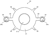
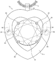
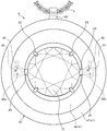
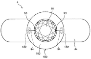
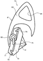
- FIG. 16 is a front view showing a ring according to the fourth embodiment.
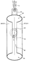
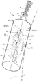
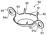
- FIG. 17 is a schematic perspective view showing a pedestal portion used for a ring.
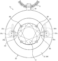
- FIG. 18 is a schematic diagram schematically showing the main part of the ring.
- the three directions orthogonal to each other are defined as the vertical direction, the width direction (left-right direction), and the front-back direction. That is, the direction in which a pair of pedestal side engagement ring portions 94 to be described later is arranged with respect to the jewel 10 is the width direction (left-right direction), and the front side and the back side of the jewel 10 (for example, the table surface and culet portion of the jewel 10)
- the direction in which the head is mainly directed is the front-rear direction
- the direction perpendicular to the width direction and the front-rear direction is the up-down direction.
- the up and down direction is a direction in which a finger is inserted into the ring, and corresponds to the up and down direction of the paper surface in FIG.
- the left-right direction is a direction in which the ring main body 4a extends from the frame portion 100 described later when the ring is viewed with the jewel 10 in the center while being orthogonal to the direction in which the finger is inserted into the ring. This corresponds to the horizontal direction of the paper surface in FIG.
- the front-rear direction is a direction orthogonal to the above-described up-down direction and left-right direction, and corresponds to the front-back direction of the paper surface in FIG.
- the direction in which the jewel can be seen is the front, and the opposite side is the rear.
- the ring 4 according to the fourth embodiment includes an annular ring main body 4a, a pedestal 90 on which diamond is fixed and held as a jewel 10, and a pedestal 90 and a jewel 10 formed integrally with the ring main body 4a. And a frame portion 100 that supports the frame. In this case, a part of the frame part 100 becomes a protective member 103 as described later.
- the pedestal portion 90 of the fourth embodiment includes a pedestal main body portion 91 on which the jewel 10 is placed, and a plurality of claw portions 92 that protrude from the pedestal main body portion 91 and fix the jewel 10.
- the left and right arm portions 93 extending from the left and right side edge portions of the pedestal main body portion 91 toward the outer side in the width direction of the pedestal portion 90, and the left and right pedestal side members disposed at the distal ends of the left and right arm portions 93 And a mating ring portion 94.
- the left and right arm portions 93 extend from the pedestal main body portion 91 to the outside in the left-right direction, and have a twisted shape so that the pedestal side engagement ring portion 94 is arranged in a posture orthogonal to the pedestal main body portion 91.
- a circular center opening 94 a is formed at the center of the left and right pedestal side engagement ring portions 94.
- the table surface of the jewel (diamond) 10 to be fixed and held is in front.
- the center opening 94a of the pedestal side engagement ring portion 94 is formed so as to face in the vertical direction.
- the frame part 100 of the fourth embodiment is formed integrally with the frame main body part 101, the left and right frame side engagement ring parts 102 fixed to the inner peripheral wall surface of the frame main body part 101, and the frame main body part 101. And an annular protective member 103 extending inward from the upper end of the frame main body 101.
- the frame main body portion 101 is formed in a bowl-like shape including a pedestal portion 90 and a storage area (space) for storing the jewel 10 inside, and a bottom surface portion 101 a disposed so as to face the curette of the jewel 10. And an inner peripheral wall surface portion 101b arranged to rise from the outer peripheral edge portion of the bottom surface portion 101a.
- the inner peripheral wall surface portion 101 b and the bottom surface portion 101 a of the frame main body portion 101 are arranged apart from the pedestal portion 90 and the jewel 10 so as to form a gap between the jewel 10.
- the left and right frame side engagement ring portions 102 have a circular center opening.
- Each frame-side engagement ring portion 102 is inclined at an angle of approximately 45 ° with respect to the front-rear direction, and the frame main body portion 101 and the protective member 103 are positioned so that the central opening portion is inclined. It is fixed at or near the boundary.
- the frame side engagement ring portion 102 only needs to be fixed to at least one of the frame main body portion 101 and the protection member 103, but the frame side engagement ring portion 102 is fixed to both the frame main body portion 101 and the protection member 103, thereby The fixing strength of the ring part 102 can be increased.
- the direction and orientation of the frame side engagement ring portion 102 and the fixing means for the frame side engagement ring portion 102 to the frame main body portion 101 are not particularly limited.
- the frame side engagement ring portion 102 is It is also possible to fix to the frame main body 101 or the protection member 103 in a posture parallel to the frame.
- the protective member 103 is arranged so as to extend inward from the upper end portion of the frame main body portion 101 toward the center portion and to incline toward the bottom surface portion 101 a of the frame main body portion 101.
- the left and right frame side engagement ring portions 102 and the pedestal side engagement ring portion 94 are engaged with each other between the protective member 103 and the inner peripheral wall surface portion 101b and the bottom surface portion 101a of the frame main body portion 101.
- a storage chamber (internal space) 104 that stores the state is provided.
- the outer surface side in the direction is covered and hidden by the protection member 103 and the bowl-shaped frame main body 101, and the entire frame-side engagement ring portion 102 and the entire pedestal-side engagement ring portion 94 are protected. That is, the frame-side engagement ring portion 102 and the pedestal-side engagement ring portion 94 according to the fourth embodiment are hidden behind the protection member 103 and cannot be seen in the front view of the ring 4 as shown in FIG. It is also possible to prevent unintentional external force (load) from being directly received from the outside.
- load unintentional external force
- the state in which the jewel 10 can be finely and smoothly swung can be stably maintained over a long period of time. It is also possible to prevent the fine swing of the hindering. As a result, the shine of the jewelry looks more beautiful, and the decoration effect and luxury of the ring 4 can be enhanced more effectively.
- At least the entire left and right frame side engagement ring portions 102 of the frame portion 100 and the connecting portion of the left and right pedestal side engagement ring portions 94 with the frame side engagement ring portion 102 are protected members.
- 103 and the frame main body 101 are only required to be protected.
- a ring is manufactured by exposing a part of the ring on the pedestal side engagement ring portion 94 other than the connection portion with the frame side engagement ring portion 102. Is also possible.
- the accessory is a pendant having the pendant tops 1, 2, and 3
- the accessory is a ring
- the present invention is not limited to a pendant or a ring, as long as it supports the jewelry fixedly held on the pedestal part so as to be swingable with respect to the frame part, and other pierced earrings, earrings, brooches, tie stoppers, etc. The same applies to jewelry.
- the frame-side engagement ring portion and the pedestal-side engagement ring portion have a circular arc (ring-like) shape in which a part of the frame-side engagement ring portion and the pedestal-side engagement ring portion are in contact with each other.
- Other portions may be formed so as to have a non-arc shape. That is, at least a part of each of the frame-side engagement ring portion and the pedestal-side engagement ring portion may be formed in an arc shape (ring shape).
- Appendix A1 It has a pedestal portion that holds and holds a jewel, and a frame portion that supports the pedestal portion, and the pedestal portion includes a pair of left and right pedestal side engagement ring portions arranged at positions facing each other with the jewel interposed therebetween.
- a pair of left and right frame side engagement ring portions that are engaged with the left and right pedestal side engagement ring portions are fixed to the frame portion, and the left and right pedestals are fixed to the left and right frame side engagement ring portions.
- the jewelry In the jewelry that is supported so as to be swingable in a state in which the pedestal part and the jewel are suspended from the frame part by connecting the side engagement ring parts, In a state where the pedestal side engaging ring portion and the frame side engaging ring portion are connected to each other, at least the left and right frame side engaging ring portions and the left and right pedestal side engaging ring portions are connected to the frame side.
- the protection member includes a front part that covers and protects the front side of the left and right frame-side engagement ring portions and the connection portion of the left and right pedestal-side engagement ring portions so as not to be exposed; and the left and right frame sides
- the rear part of the engagement ring part and the left and right of the pedestal side engagement ring part is covered and protected so as not to be exposed, and the rear part is fixed to the front part.
- the pedestal portion and the jewel are supported so as to be swingable in a suspended state with respect to the frame portion so that the front side (for example, the table surface) of the jewel can be seen from the front (described later).
- the front side for example, the table surface
- the gemstone may be a natural gemstone (natural mineral) such as diamond or sapphire, a synthetic gemstone (artificial gemstone) using a synthesized mineral, a counterfeit gemstone using glass or the like (Appendix A8, B1 to be described later) , B11, C1, and C9).
- natural gemstone natural mineral
- synthetic gemstone artificial gemstone
- a counterfeit gemstone using glass or the like Appendix A8, B1 to be described later
- each of the pair of left and right pedestal side engaging ring portions and the pair of left and right frame side engaging ring portions is formed in an arc shape (preferably annular).
- the left and right pedestal-side engagement ring portions and the left and right frame-side engagement ring portions are connected to each other so that the respective arc-shaped inner peripheral edge portions are in contact with each other (Appendixes A8, B1, and B11 described later) The same applies to C1, C9).
- the left and right frame-side engagement ring portions and the connecting portions of the left and right pedestal-side engagement ring portions to the frame-side engagement ring portion are protected from the outside by the protection member.
- the front sides of the left and right frame-side engagement ring portions and the connecting portions of the left and right pedestal-side engagement ring portions are covered and protected so as not to be exposed by the front parts of the protection member.
- the back sides of the left and right frame-side engagement ring portions and the connecting portions of the left and right pedestal-side engagement ring portions are covered and protected so as not to be exposed by the rear parts of the protection member.
- front parts and rear parts specifically, the front side, the back side, the top side, the bottom side, and the connection part of the left and right frame side engagement ring portions and the left and right pedestal side engagement ring portions, And it is covered and protected from the outside so that the outer surface side in the width direction is not exposed.
- connection part of the base side engagement ring part with respect to a frame side engagement ring part is a ring part of the base side engagement ring part connected and contacted with a frame side engagement ring part.
- the connecting portion (ring portion) includes a range (region) in which the inner peripheral edge of the frame side engaging ring portion is in sliding contact when the jewel is slightly swung.
- the pedestal side engaging ring portion is a connecting portion in which the arc-shaped portion of the pedestal side engaging ring portion is connected to the frame side engaging ring portion and slidably contacts the inner peripheral edge of the frame side engaging ring portion. (The same applies to A8, B1, B11, C1, and C9 described later).
- the protection member is disposed outside the base-side engagement ring portion and the frame-side engagement ring portion in the connected state except for the swingable range of the base portion so as not to interfere with the swinging base portion ( The same applies to supplementary notes B1 and C1 described later).
- the protection member may protect the pedestal side engagement ring portion and the frame side engagement ring portion only with the protection member, or may be formed separately from the protection member and the protection member.
- the pedestal-side engagement ring portion and the frame-side engagement ring portion may be protected by a part of the frame portion (the same applies to additional notes B1 and C1 described later).
- the pedestal portion is stably supported with respect to the frame portion so as to be swingable via the pedestal side engagement ring portion and the frame side engagement ring portion. Further, at least the above-described connecting portion of the pedestal side engagement ring portion and the frame side engagement ring are protected by the protective member so as not to be exposed to the outside. For this reason, the connecting structure portion that allows the jewel base side engagement ring portion and the frame side engagement ring portion to be connected to each other to allow minute swinging of the gemstone is not intended by directly colliding with another object. Receiving external force can be prevented with a simple structure (the same applies to additional notes B1 and C1 described later).
- the pedestal side engagement ring portion and the frame side engagement ring portion are protected by the protection member, it is possible to make it difficult to entangle hair, yarn, and the like with the pedestal side engagement ring portion and the frame side engagement ring portion. . Thereby, the handleability of the jewelry can be improved, and the swinging movement of the pedestal and the jewel can be prevented from being entangled with the thread or the like (the same applies to the appendices B1 and C1 described later).
- the protective member can be formed with a simple structure. After connecting the left and right pedestal side engaging ring parts arranged on the pedestal part to the left and right frame side engaging ring parts arranged on the frame part respectively, the front parts and The protective member can be formed by fixing the rear parts to each other. Thereby, it is possible to easily and stably manufacture a garment in which the pedestal part and the jewelry are swingably arranged and the pedestal side engagement ring part and the frame side engagement ring part are protected by the protective member. Yes (the same applies to Appendices B6 and C4 described later).
- Appendix A2 The ornament according to Appendix A1, wherein the frame-side engagement ring portion and the pedestal-side engagement ring portion are protected by the protection member.
- At least the front side, the back side, the upper side, the lower side, and the outer side in the width direction of the entire pedestal side engaging ring part and the frame side engaging ring part in the connected state Can be covered with a protective member so as not to be exposed to the outside, and can be stably protected. For this reason, the pedestal side engagement ring part and the frame side engagement ring part in a connected state are reliably prevented from receiving an unintended external force by directly colliding with another object, etc.
- the swingable state can be maintained more stably over a long period of time (the same applies to additional notes B3 and C2 described later).
- Appendix A3 The ornament according to appendix A1, wherein at least a part of the pedestal side engagement ring portion other than the connection portion is exposed.
- the frame-side engagement ring portion and the pedestal-side engagement ring portion are protected by the protection member so that at least a portion other than the connection portion in the pedestal-side engagement ring portion is exposed. It is also possible. This also makes it possible to stably maintain a minute swingable state of the pedestal and the gemstone over a long period of time (the same applies to additional notes B5 and C3 described later).
- Appendix A4 The accessory according to any one of Appendix A1 to Appendix A3, wherein the front part and the rear part have a symmetrical shape.
- parts (parts) having the same shape and the same material can be used as the front part and the rear part.
- the front part and the rear part of the protection member can be manufactured at low cost.
- the front part and the rear part are not mistaken, so the work of attaching the protective member is prevented from becoming complicated, and the attachment work is efficiently performed. Can be done.
- parts with completely different shapes or parts with completely different materials for the front part and the rear part are also possible to use parts with completely different shapes or parts with completely different materials for the front part and the rear part (the same applies to the appendices B7 and C5 described later).
- the protective member simultaneously connects one of the pedestal side engaging ring part and the frame side engaging ring part, and the other connected pedestal side engaging ring part and the frame side engaging ring part at the same time.
- the protective member can be formed with a simple structure. Further, the protection member can be easily and stably attached to the outside of the left and right pedestal side engagement ring portions and the frame side engagement ring portion, whereby the pedestal side engagement ring portion and the frame side engagement ring. The portion is stably protected (the same applies to additional notes B8 and C6 described later).
- the protective member constitutes at least a part of the frame part, The ornament according to any one of appendices A1 to A5, wherein the frame-side engagement ring portion is fixed to an inner surface of the protection member.
- the protection member is formed so as to constitute at least a part of the frame portion (frame main body portion), and the frame-side engagement ring portion is fixed to the inner surface of the protection member.
- the frame portion can be formed with a simple structure, and the pedestal-side engagement ring portion and the frame-side engagement ring portion in the connected state can be reliably protected by the protective member that constitutes the frame portion.
- the protective member is not formed as a part of the frame portion, and the frame portion may be formed separately from the protective member as a member having the frame main body portion and the frame side engagement ring portion (the above points are The same applies to supplementary notes B9 and C7 described later).
- the protective member has a hollow shape, so that the pedestal side engagement ring portion and the frame side engagement ring portion in a connected state are stably accommodated inside the protective member.
- the hollow protective member can be stably formed by, for example, pressing a metal thin plate material, and the raw material cost is lower than, for example, a solid protective member in which the interior is buried. It can be kept low (the same applies to additional notes B10 and C8 described later).
- Appendix A8 It has a pedestal portion that holds and holds a jewel, and a frame portion that supports the pedestal portion, and the pedestal portion includes a pair of left and right pedestal side engagement ring portions arranged at positions facing each other with the jewel interposed therebetween.
- a pair of left and right frame side engagement ring portions that are engaged with the left and right pedestal side engagement ring portions are fixed to the frame portion, and the left and right pedestals are fixed to the left and right frame side engagement ring portions.
- the frame portion includes at least the left and right frame-side engagement ring portions and the left and right pedestal-side engagement ring portions in a state where the pedestal-side engagement ring portion and the frame-side engagement ring portion are connected to each other.
- a front part that covers and protects the front side of the connecting part to the frame side engaging ring part so as not to be exposed, and the connecting part of the left and right frame side engaging ring parts and the left and right base side engaging ring parts And the rear part fixed to the front part while covering and protecting the back side so as not to be exposed,
- a storage chamber is provided between the front part and the rear part to house at least the frame-side engagement ring portion and the connection portion of the pedestal-side engagement ring portion to protect them from the outside.
- the front sides of the left and right frame-side engagement ring portions and the connecting portions of the left and right pedestal-side engagement ring portions are covered and protected so as not to be exposed by the front parts of the frame portion.
- the back sides of the left and right frame-side engagement ring portions and the connecting portions of the left and right pedestal-side engagement ring portions are covered and protected so as not to be exposed by the rear parts of the frame portion.
- the front part and the rear part are fixed to each other, and a storage chamber is arranged between them.
- the frame-side engagement ring portion and the connecting portion of the pedestal-side engagement ring portion with respect to the frame-side engagement ring portion are accommodated inside the accommodation chamber and are protected from the outside by the front parts and the rear parts.
- the front and back surfaces of the left and right frame-side engagement ring portions and the connecting portions of the left and right pedestal-side engagement ring portions are determined by the frame portions (front parts and rear parts) having such a storage chamber.
- the outer side, the upper side, the lower side and the outer side in the width direction are covered and protected from the outside so as not to be exposed.
- the frame portion having the storage chamber is outside the pedestal side engagement ring portion and the frame side engagement ring portion in a connected state, except for the swingable range of the pedestal portion, so as not to interfere with the swinging pedestal portion. (The same applies to additional notes B11 and C9 described later).
- the pedestal portion is stably supported so as to be swingable with respect to the frame portion via the pedestal side engagement ring portion and the frame side engagement ring portion.
- the connecting portion of the base side engaging ring part and the frame side engaging ring part are accommodated in the accommodating chamber of the frame part and are protected from being exposed to the outside.
- the connecting structure portion that allows the jewel base side engagement ring portion and the frame side engagement ring portion to be connected to each other to allow minute swinging of the gemstone is not intended by directly colliding with another object. Receiving external force can be prevented with a simple structure (the same applies to additional notes B11 and C9 described later).
- the pedestal side engagement ring portion and the frame side engagement ring portion are accommodated and protected in the accommodation chamber of the frame portion, so that hair and yarn can be transferred to the pedestal side engagement ring portion and the frame side engagement ring portion. It can be difficult to get tangled. Thereby, it is possible to improve the handleability of the jewelry, and it is also possible to prevent the swinging movement of the pedestal part and the jewel due to the entanglement of the yarn or the like (the same applies to the supplementary notes B11 and C9 described later).
- the pedestal side engagement ring part and the frame side engagement ring part are held in the housing chamber of the frame part so that they can be hidden from view or difficult to see from outside, thereby reducing restrictions on the design of accessories. Therefore, the degree of freedom in design is expanded, and design variations can be easily increased (the same applies to additional notes B11 and C9 described later).
- the frame part By using a frame part (frame body part) having front parts and rear parts, the frame part can be formed with a simple structure.
- the left and right pedestal side engagement ring portions arranged on the pedestal portion are respectively connected to the left and right frame side engagement ring portions arranged on the front part or rear part, and then these ring portions are protected.
- the front part and the rear part can be fixed to each other to form a frame part (frame body part).
- the pedestal part and the jewel are swingably arranged and the pedestal side engagement ring part and the frame side engagement ring part are protected by the frame part. Yes (the same applies to additional notes B16 and C12 described later).
- Appendix A9 The ornament according to appendix A8, wherein the housing chamber accommodates the entire frame-side engagement ring portion and the pedestal-side engagement ring portion.
- the entire frame-side engagement ring portion and the pedestal-side engagement ring portion are accommodated in the housing chamber of the frame portion, so that the entire frame-side engagement ring portion and the pedestal-side engagement can be obtained.
- the entire coupling part is protected by the frame part.
- the front side, the back side, the top side, the bottom side, and the outer side in the width direction of the left and right frame side engagement ring portions and the connecting portions of the left and right pedestal side engagement ring portions are exposed to the outside. It can be hidden and protected stably.
- the pedestal side engagement ring part and the frame side engagement ring part in a connected state are reliably prevented from receiving an unintended external force by directly colliding with another object, etc.
- the swingable state can be maintained more stably over a long period of time (the same applies to additional notes B13 and C10 described later).
- Appendix A10 The ornament according to appendix A8, wherein at least a part of the pedestal side engagement ring portion other than the connection portion is exposed.
- the frame-side engagement ring portion and the pedestal-side engagement ring portion are disposed in the housing chamber of the frame portion so that at least a part other than the connection portion in the pedestal-side engagement ring portion is exposed. Even if it accommodates, a pedestal part and the minute rockable state of a jewel can be stably maintained over a long period of time (the same applies to Appendices B15 and C11 described later).
- parts (parts) having the same shape and the same material can be used as the front part and the rear part.
- a front part and a rear part can be produced at low cost.
- the hollow frame main body can be formed stably by, for example, pressing a metal thin plate material, and the raw material cost is lower than that of a solid frame main body in which the interior is buried. Can be kept low (the same applies to B16 and C12 described later).
- the frame part has an insertion opening for inserting a part of the base part,
- the insertion opening has a size that allows swinging of the pedestal and the jewel, and at the same time restricts a swing range of the pedestal and the jewel.
- the frame portion has a shape surrounding the outer periphery of the jewel held on the pedestal portion and having a gap between the jewel and the jewelry when viewed from the front side.
- the ornament according to any one of Appendix A12.
- the frame portion can protect the entire pedestal portion and the surroundings of the jewelry.
- the jewel appears to be floating in the air with respect to the pedestal and the frame disposed near the outer periphery of the jewel, and the sway of the jewel is easily emphasized by the fine swing of the pedestal and the jewel. .
- the shine of the jewelry held on the pedestal can be seen more beautifully, and the decoration effect and luxury of the jewelry can be enhanced more effectively.
- the frame part around the pedestal part and the jewel it is difficult for the pedestal part and the jewel to come into contact with the user's clothing, etc. Can stop the swinging of the pedestal and the jewel (the above points are the same in the appendices B19 and C14 described later).
- Appendix A14 In the side view of the accessory, with respect to the front and back direction of the accessory, the back side end surface of the frame part is arranged at a position on the back side further than the position of the tip side of the back side of the rockable gemstone.
- Appendix B1 It has a pedestal portion that holds and holds a jewel, and a frame portion that supports the pedestal portion, and the pedestal portion includes a pair of left and right pedestal side engagement ring portions arranged at positions facing each other with the jewel interposed therebetween.
- the frame portion includes a pair of left and right frame side engagement ring portions to which the left and right pedestal side engagement ring portions are coupled and engaged, and the left and right frame side engagement ring portions are provided with the left and right frame side engagement ring portions.
- the jewelry In the jewelry that is supported so as to be swingable in a state where the pedestal part and the jewel are suspended from the frame part by connecting the pedestal side engagement ring parts, In a state where the pedestal side engaging ring portion and the frame side engaging ring portion are connected to each other, at least the left and right frame side engaging ring portions and the left and right pedestal side engaging ring portions are connected to the frame side. It has a protective member that covers and protects from the outside so as not to expose the front side, the back side, the top side, the bottom side, and the outer side in the width direction of the connecting part to the coupling ring part. Jewelry.
- the front side, the back side, the top side, the bottom side, and the left and right frame side engagement ring portions and the connecting portions of the left and right pedestal side engagement ring portions to the frame side engagement ring portion is covered and protected from the outside by the protective member so that the outer surface side in the width direction is not exposed.
- At least a part of the pedestal side engagement ring portion is formed in an arc shape
- At least a part of the frame side engagement ring portion is formed in an arc shape
- the pedestal part and the jewel are supported so as to be swingable in a state of being suspended from the frame part so that the table surface of the jewel is visible from the front.
- the left and right pedestal side engagement ring portions are slid onto the inner peripheral edge of the frame side engagement ring portion by connecting the arcuate portion of the pedestal side engagement ring portion to the frame side engagement ring portion.
- the protective member includes at least a front front side, a rear back side, an upper surface side, a lower surface side, and a front side of the left and right frame side engagement ring portions and the connection portion of the left and right base side engagement ring portions; Cover and protect continuously from the outside so as not to expose the outer surface side in the width direction, Apparel as described in Appendix B1.
- Appendix B3 The protection member protects the entire frame side engagement ring portion and the pedestal side engagement ring portion, The jewelry according to Appendix B1 or Appendix B2.
- the pedestal side engagement ring part and the frame side engagement ring part are each formed in an annular shape
- the protective member includes a front front side and a rear side of the frame side engagement ring part and the base side engagement ring part. Cover and protect continuously from the outside so that the back side, top side, bottom side, and outside side in the width direction are not exposed. Apparel described in Appendix B3.
- the protection member includes a front part that protects a front side of the pedestal side engagement ring portion and the connection portion of the frame side engagement ring portion, the pedestal side engagement ring portion, and the frame side engagement ring portion.
- the accessory according to any one of Supplementary Note B1 to Supplementary Note B5, comprising a rear part that protects a back side of the connection part and a rear part that is fixed to the front part.
- Appendix B7 The accessory according to Appendix B6, wherein the front part and the rear part have symmetrical shapes.
- Appendix B8 The protective member simultaneously connects one of the pedestal side engaging ring part and the frame side engaging ring part, and the other connected pedestal side engaging ring part and the frame side engaging ring part at the same time.
- the protective member constitutes at least a part of the frame part, The ornament according to any one of Appendix B1 to Appendix B8, wherein the frame-side engagement ring portion is fixed to an inner surface of the protection member.
- Appendix B10 The accessory according to any one of Appendix B1 to Appendix B9, wherein the protective member has a hollow shape.
- Appendix B11 It has a pedestal portion that holds and holds a jewel, and a frame portion that supports the pedestal portion, and the pedestal portion includes a pair of left and right pedestal side engagement ring portions arranged at positions facing each other with the jewel interposed therebetween.
- the frame portion includes a pair of left and right frame side engagement ring portions to which the left and right pedestal side engagement ring portions are coupled and engaged, and the left and right frame side engagement ring portions are provided with the left and right frame side engagement ring portions.
- the frame portion includes at least the frame side engagement ring portion and the frame side of the pedestal side engagement ring portion in a state where the pedestal side engagement ring portion and the frame side engagement ring portion are connected to each other.
- a connecting portion with respect to the engaging ring portion is housed therein, and the front side, the back side, and the upper surface side of the left and right frame side engaging ring portions and the connecting portion of the left and right pedestal side engaging ring portions;
- a garment characterized by having a storage chamber that covers and protects the lower surface side and the outer surface side in the width direction from the outside so as not to be exposed.
- the frame-side engagement ring portion and the connecting portion of the pedestal-side engagement ring portion to the frame-side engagement ring portion are housed inside the housing portion of the frame portion.
- the frame portion is covered and protected from the outside so that the side surface is not exposed.
- At least a part of the pedestal side engagement ring portion is formed in an arc shape
- At least a part of the frame side engagement ring portion is formed in an arc shape
- the pedestal part and the jewel are supported so as to be swingable in a state of being suspended from the frame part so that the table surface of the jewel is visible from the front.
- the left and right pedestal side engagement ring portions are slid onto the inner peripheral edge of the frame side engagement ring portion by connecting the arcuate portion of the pedestal side engagement ring portion to the frame side engagement ring portion.
- the direction in which the pair of pedestal side engagement ring portions are arranged with respect to the gemstone is the width direction
- the direction in which the table surface and the curette portion of the gemstone mainly faces is Direction
- the housing chamber accommodates the frame-side engagement ring portion and the connecting portion of the pedestal-side engagement ring portion inside, and includes at least the left and right frame-side engagement ring portions and the left and right pedestal-side engagements.
- the front side, the rear side, the upper side, the lower side, and the outer side in the width direction are continuously covered and protected from the outside so as not to be exposed in the coupling portion of the coupling part. Apparel described in appendix B11.
- the pedestal side engagement ring part and the frame side engagement ring part are each formed in an annular shape
- the storage chamber includes a front front side and a rear side of the frame side engagement ring part and the base side engagement ring part.
- the back side, the upper side, the lower side, and the outer side in the width direction are continuously covered from the outside so as not to be exposed. Apparel described in appendix B13.
- the frame main body portion of the frame portion includes a front part that protects a front side of the pedestal side engaging ring portion and the connecting portion of the frame side engaging ring portion, and the pedestal side engaging ring portion and the frame side.
- a rear part that protects the back side of the engagement ring part and the connection part and is fixed to the front part,
- the front part and the rear part have symmetrical shapes,
- the jewelry according to any one of Supplementary Note B11 to Supplementary Note B15, wherein the frame main body portion has a hollow shape forming the storage chamber.
- the frame part has an insertion opening for inserting a part of the base part,
- the insertion opening has a size that allows swinging of the pedestal and the jewel, and at the same time restricts a swinging range of the pedestal and the jewel.
- the pedestal portion includes a pedestal main body on which the jewel is placed and fixedly held, and left and right arm portions that connect the pedestal main body portion and the left and right pedestal side engagement ring portions, The insertion opening allows the arm portion of the pedestal portion to be inserted; Apparel described in Appendix B17.
- the frame portion has a shape surrounding the outer periphery of the jewel held on the pedestal portion and having a gap between the jewel when the accessory is viewed from the front side.
- the ornament according to any one of Appendix B18.
- Appendix B20 In the side view of the accessory, with respect to the front and back direction of the accessory, the back side end surface of the frame part is arranged at a position on the back side further than the position of the back side tip part of the rockable gemstone.
- the accessory according to any one of Appendix B19.
- Appendix C1 It has a pedestal portion that holds and holds a jewel, and a frame portion that supports the pedestal portion, and the pedestal portion includes a pair of left and right pedestal side engagement ring portions arranged at positions facing each other with the jewel interposed therebetween.
- the frame portion includes a pair of left and right frame side engagement ring portions to which the left and right pedestal side engagement ring portions are coupled and engaged, and the left and right frame side engagement ring portions are provided with the left and right frame side engagement ring portions.
- a decorative product comprising a protective member that protects the connecting portion from the outside.
- the left and right frame-side engagement ring portions and the connecting portions of the left and right pedestal-side engagement ring portions to the frame-side engagement ring portion are protected from the outside by the protection member.
- the front side, the back side, the top side, the bottom side, and the outside in the width direction of the left and right frame side engagement ring portions and the connecting portion of the left and right base side engagement ring portions It is covered and protected from the outside so that the side face is not exposed.
- Appendix C2 The jewelry according to Appendix C1, wherein the frame-side engagement ring portion and the pedestal-side engagement ring portion are protected by the protection member.
- Appendix C3 The ornament according to appendix C1, wherein at least a part of the pedestal side engagement ring portion other than the connection portion is exposed.
- the protection member protects the front parts that protect the front surfaces of the pedestal side engagement ring portion and the frame side engagement ring portion, and the back surface of the pedestal side engagement ring portion and the frame side engagement ring portion.
- the accessory according to any one of Appendix C1 to Appendix C3, comprising a rear part fixed to the front part.
- Appendix C5 The accessory according to Appendix C4, wherein the front part and the rear part have symmetrical shapes.
- Appendix C6 The protective member simultaneously connects one of the pedestal side engaging ring part and the frame side engaging ring part, and the other connected pedestal side engaging ring part and the frame side engaging ring part at the same time.
- the protective member constitutes at least a part of the frame part, The ornament according to any one of Supplementary Notes C1 to C6, wherein the frame-side engagement ring portion is fixed to an inner surface of the protection member.
- Appendix C8 The accessory according to any one of Appendix C1 to Appendix C7, wherein the protective member has a hollow shape.
- Appendix C9 It has a pedestal portion that holds and holds a jewel, and a frame portion that supports the pedestal portion, and the pedestal portion includes a pair of left and right pedestal side engagement ring portions arranged at positions facing each other with the jewel interposed therebetween.
- the frame portion includes a pair of left and right frame side engagement ring portions to which the left and right pedestal side engagement ring portions are coupled and engaged, and the left and right frame side engagement ring portions are provided with the left and right frame side engagement ring portions.
- the frame portion includes at least the frame side engagement ring portion and the frame side of the pedestal side engagement ring portion in a state where the pedestal side engagement ring portion and the frame side engagement ring portion are connected to each other.
- a decorative article characterized by comprising a storage chamber for storing a connecting portion with respect to the engagement ring portion inside and protecting it from the outside.
- the frame side engagement ring portion and the connecting portion of the pedestal side engagement ring portion with respect to the frame side engagement ring portion are accommodated inside the accommodation chamber of the frame portion and protected from the outside.
- the front side, the back side, the top side, the bottom side, and the left and right frame side engagement ring portions and the connecting portions of the left and right pedestal side engagement ring portions to the frame side engagement ring portion And it is covered and protected from the outside by the frame portion so that the outer surface side in the width direction is not exposed.
- Appendix C10 The ornament according to appendix C9, wherein the housing chamber accommodates the entire frame-side engagement ring portion and the pedestal-side engagement ring portion.
- Appendix C11 The ornament according to appendix C9, wherein at least a part of the pedestal side engagement ring portion other than the connection portion is exposed.
- the frame main body portion of the frame portion includes a front part that protects a front surface of the pedestal side engagement ring portion and the frame side engagement ring portion, and a back surface of the pedestal side engagement ring portion and the frame side engagement ring portion. And rear parts that are fixed to the front parts, The front part and the rear part have symmetrical shapes,
- the frame part has an insertion opening for inserting a part of the base part,
- the insertion opening has a size that allows swinging of the pedestal portion and the jewel, and at the same time restricts a swing range of the pedestal portion and the jewel.
- the frame portion surrounds the outer periphery of the jewel held on the pedestal portion when the accessory is viewed from the front side, and has a shape with a gap between the jewel and the appendix C1-
Landscapes
- Adornments (AREA)
Abstract
Description
以下の説明では、身飾品(ペンダント)において互いに直交する3つの方向を、上下方向、幅方向(左右方向とも呼ぶ)及び前後方向とする。すなわち、後述する宝石10に対して一対の台座側係合リング部24が配される方向を幅方向とし、宝石10の表側と裏側(例えば宝石10のテーブル面とキューレット部11)が主として向く方向を前後方向とし、幅方向及び前後方向に直交する方向を上下方向とする。具体的には、上下方向及び左右方向は、ペンダントトップをペンダントのチェーンに取り付けて持ち上げた状態における上下方向及び左右方向のことであり、前後方向は、ペンダントが着用されたときのペンダントトップの正面側の方向(前方)及び背面側の方向(後方)のことである。
本実施例2に係るペンダントトップ2は、宝石(ダイヤモンド)10が固定保持される台座部20と、その台座部20及び宝石(ダイヤモンド)10を支持するとともに保護部材として形成されるフレーム部40とを有する。
宝石を固定保持する台座部と、前記台座部を支持するフレーム部とを有し、前記台座部は、前記宝石を挟んで相対する位置に配される左右一対の台座側係合リング部を備え、前記フレーム部に、左右の前記台座側係合リング部がそれぞれ連結されて係合する左右一対のフレーム側係合リング部が固定され、左右の前記フレーム側係合リング部に左右の前記台座側係合リング部がそれぞれ連結されることにより前記台座部及び前記宝石が前記フレーム部に対して吊り下げられた状態で揺動可能に支持される身飾品において、
前記台座側係合リング部及び前記フレーム側係合リング部が相互に連結された状態で、少なくとも左右の前記フレーム側係合リング部と、左右の前記台座側係合リング部の前記フレーム側係合リング部に対する連結部分とを外側から保護する保護部材を有し、
前記保護部材は、左右の前記フレーム側係合リング部と左右の前記台座側係合リング部の前記連結部分との正面側を露出しないように覆って保護するフロントパーツと、左右の前記フレーム側係合リング部と左右の前記台座側係合リング部の前記連結部分との背面側を露出しないように覆って保護するとともに前記フロントパーツに固定されるリアパーツとを有してなる、
ことを特徴とする身飾品。
前記保護部材により、前記フレーム側係合リング部及び前記台座側係合リング部の全体が保護されてなる
付記A1に記載の身飾品。
前記台座側係合リング部における前記連結部分以外の少なくとも一部が露出してなる
付記A1に記載の身飾品。
前記フロントパーツと前記リアパーツとは表裏対称的な形状を有してなる
付記A1~付記A3のいずれか1つに記載の身飾品。
前記保護部材は、連結された一方の前記台座側係合リング部及び前記フレーム側係合リング部と、連結された他方の前記台座側係合リング部及び前記フレーム側係合リング部とを同時に保護する単一の一体的な形状を有してなる
付記A1~付記A4のいずれか1つに記載の身飾品。
前記保護部材は、前記フレーム部の少なくとも一部を構成し、
前記保護部材の内面に、前記フレーム側係合リング部が固定されてなる
付記A1~付記A5のいずれか1つに記載の身飾品。
[付記A7]
前記保護部材は、中空形状を有してなる
付記A1~付記A6のいずれか1つに記載の身飾品。
宝石を固定保持する台座部と、前記台座部を支持するフレーム部とを有し、前記台座部は、前記宝石を挟んで相対する位置に配される左右一対の台座側係合リング部を備え、前記フレーム部に、左右の前記台座側係合リング部がそれぞれ連結されて係合する左右一対のフレーム側係合リング部が固定され、左右の前記フレーム側係合リング部に左右の前記台座側係合リング部がそれぞれ連結されることにより前記台座部及び前記宝石が前記フレーム部に対して吊り下げられた状態で揺動可能に支持される身飾品において、
前記フレーム部は、前記台座側係合リング部及び前記フレーム側係合リング部が相互に連結された状態で、少なくとも左右の前記フレーム側係合リング部と左右の前記台座側係合リング部の前記フレーム側係合リング部に対する連結部分との正面側を露出しないように覆って保護するフロントパーツと、左右の前記フレーム側係合リング部と左右の前記台座側係合リング部の前記連結部分との背面側を露出しないように覆って保護するとともに前記フロントパーツに固定されるリアパーツとを有し、
前記フロントパーツと前記リアパーツの間に、少なくとも前記フレーム側係合リング部と、前記台座側係合リング部の前記連結部分とを内部に収容して外側から保護する収容室が配されてなる
ことを特徴とする身飾品。
前記収容室に、前記フレーム側係合リング部及び前記台座側係合リング部の全体が収容されてなる
付記A8に記載の身飾品。
前記台座側係合リング部における前記連結部分以外の少なくとも一部が露出してなる
付記A8に記載の身飾品。
前記フロントパーツと前記リアパーツとは表裏対称的な形状を有し、
前記フレーム部のフレーム本体部は、前記収容室を形成する中空の形状を有してなる
付記A8~付記A10のいずれか1つに記載の身飾品。
前記フレーム部は、前記台座部の一部を挿通させる挿通開口部を有し、
前記挿通開口部は、前記台座部及び前記宝石の揺動を許容すると同時に、前記台座部及び前記宝石の揺動範囲を規制する大きさを有してなる
付記A1~付記A11のいずれか1つに記載の身飾品。
前記フレーム部は、前記身飾品を正面側から見たとき、前記台座部に保持された前記宝石の外周を取り囲み、且つ、前記宝石との間に隙間のある形状を有してなる
付記A1~付記A12のいずれか1つに記載の身飾品。
前記身飾品の側面視において、前記身飾品の表裏方向に関し、前記フレーム部の裏側端面は、揺動可能な前記宝石の裏面側先端部の位置よりも更に裏側の位置に配されてなる
付記A1~付記A13のいずれか1つに記載の身飾品。
宝石を固定保持する台座部と、前記台座部を支持するフレーム部とを有し、前記台座部は、前記宝石を挟んで相対する位置に配される左右一対の台座側係合リング部を備え、前記フレーム部は、左右の前記台座側係合リング部がそれぞれ連結されて係合する左右一対のフレーム側係合リング部を備え、且つ、左右の前記フレーム側係合リング部に左右の前記台座側係合リング部がそれぞれ連結されることにより前記台座部及び前記宝石が前記フレーム部に対して吊り下げられた状態で揺動可能に支持される身飾品において、
前記台座側係合リング部及び前記フレーム側係合リング部が相互に連結された状態で、少なくとも左右の前記フレーム側係合リング部と、左右の前記台座側係合リング部の前記フレーム側係合リング部に対する連結部分とにおける正面側、背面側、上面側、下面側、及び幅方向の外側面側を露出しないように外側から覆って保護する保護部材を有してなる
ことを特徴とする身飾品。
前記台座側係合リング部の少なくとも一部が円弧状に形成され、
前記フレーム側係合リング部の少なくとも一部が円弧状に形成され、
前記台座部及び前記宝石は、前記宝石のテーブル面が正面から見えるようにして、前記フレーム部に対して吊り下げられた状態で揺動可能に支持され、
左右の前記台座側係合リング部は、当該台座側係合リング部の円弧状の部分が前記フレーム側係合リング部に連結して前記フレーム側係合リング部の内周端縁部に摺接する連結部分を有し、
前記身飾品において互いに直交する3方向として、前記宝石に対して一対の前記台座側係合リング部が配される方向を幅方向とし、前記宝石のテーブル面及びキューレット部が主として向く方向を前後方向とし、前記幅方向及び前記前後方向に直交する方向を上下方向とした場合、
前記保護部材は、少なくとも左右の前記フレーム側係合リング部と、左右の前記台座側係合リング部の前記連結部分とにおける前方の正面側、後方の背面側、上面側、下面側、及び前記幅方向の外側面側を露出しないように外側から連続的に覆って保護する、
付記B1に記載の身飾品。
前記保護部材は、前記フレーム側係合リング部及び前記台座側係合リング部の全体を保護する、
付記B1又は付記B2に記載の身飾品。
前記台座側係合リング部及び前記フレーム側係合リング部が、それぞれ環状に形成され、
前記保護部材は、前記フレーム側係合リング部の全体と前記台座側係合リング部の全体とを、前記フレーム側係合リング部及び前記台座側係合リング部における前方の正面側、後方の背面側、上面側、下面側、及び幅方向の外側面側を露出しないように、外側から連続的に覆って保護する、
付記B3に記載の身飾品。
前記台座側係合リング部における前記連結部分以外の少なくとも一部が露出してなる
付記B1又は付記B2に記載の身飾品。
前記保護部材は、前記台座側係合リング部と前記フレーム側係合リング部の前記連結部分との正面側を保護するフロントパーツと、前記台座側係合リング部と前記フレーム側係合リング部の前記連結部分との背面側を保護するとともに前記フロントパーツに固定されるリアパーツとを有してなる
付記B1~付記B5のいずれか1つに記載の身飾品。
前記フロントパーツと前記リアパーツとは表裏対称的な形状を有してなる
付記B6に記載の身飾品。
前記保護部材は、連結された一方の前記台座側係合リング部及び前記フレーム側係合リング部と、連結された他方の前記台座側係合リング部及び前記フレーム側係合リング部とを同時に保護する単一の一体的な形状を有してなる
付記B1~付記B7のいずれか1つに記載の身飾品。
前記保護部材は、前記フレーム部の少なくとも一部を構成し、
前記保護部材の内面に、前記フレーム側係合リング部が固定されてなる
付記B1~付記B8のいずれか1つに記載の身飾品。
前記保護部材は、中空形状を有してなる
付記B1~付記B9のいずれか1つに記載の身飾品。
宝石を固定保持する台座部と、前記台座部を支持するフレーム部とを有し、前記台座部は、前記宝石を挟んで相対する位置に配される左右一対の台座側係合リング部を備え、前記フレーム部は、左右の前記台座側係合リング部がそれぞれ連結されて係合する左右一対のフレーム側係合リング部を備え、且つ、左右の前記フレーム側係合リング部に左右の前記台座側係合リング部がそれぞれ連結されることにより前記台座部及び前記宝石が前記フレーム部に対して吊り下げられた状態で揺動可能に支持される身飾品において、
前記フレーム部は、前記台座側係合リング部及び前記フレーム側係合リング部が相互に連結された状態で、少なくとも前記フレーム側係合リング部と、前記台座側係合リング部の前記フレーム側係合リング部に対する連結部分とを内部に収容して、左右の前記フレーム側係合リング部と、左右の前記台座側係合リング部の前記連結部分とにおける正面側、背面側、上面側、下面側、及び幅方向の外側面側を露出しないように外側から覆って保護する収容室を有してなる
ことを特徴とする身飾品。
前記台座側係合リング部の少なくとも一部が円弧状に形成され、
前記フレーム側係合リング部の少なくとも一部が円弧状に形成され、
前記台座部及び前記宝石は、前記宝石のテーブル面が正面から見えるようにして、前記フレーム部に対して吊り下げられた状態で揺動可能に支持され、
左右の前記台座側係合リング部は、当該台座側係合リング部の円弧状の部分が前記フレーム側係合リング部に連結して前記フレーム側係合リング部の内周端縁部に摺接する連結部分を有し、
前記身飾品において互いに直交する3方向として、前記宝石に対して一対の前記台座側係合リング部が配される方向を幅方向とし、前記宝石のテーブル面及びキューレット部が主として向く方向を前後方向とし、前記幅方向及び前記前後方向に直交する方向を上下方向とした場合、
前記収容室は、前記フレーム側係合リング部と、前記台座側係合リング部の前記連結部分とを内部に収容し、少なくとも左右の前記フレーム側係合リング部と、左右の前記台座側係合リング部の前記連結部分とにおける前方の正面側、後方の背面側、上面側、下面側、及び前記幅方向の外側面側を露出しないように外側から連続的に覆って保護する、
付記B11に記載の身飾品。
前記収容室は、前記フレーム側係合リング部及び前記台座側係合リング部の全体を収容する、
付記B11又は付記B12に記載の身飾品。
前記台座側係合リング部及び前記フレーム側係合リング部が、それぞれ環状に形成され、
前記収容室は、前記フレーム側係合リング部の全体と前記台座側係合リング部の全体とを、前記フレーム側係合リング部及び前記台座側係合リング部における前方の正面側、後方の背面側、上面側、下面側、及び幅方向の外側面側を露出しないように、外側から連続的に覆って収容する、
付記B13に記載の身飾品。
前記台座側係合リング部における前記連結部分以外の少なくとも一部が露出してなる
付記B11又は付記B12に記載の身飾品。
前記フレーム部のフレーム本体部は、前記台座側係合リング部と前記フレーム側係合リング部の前記連結部分との正面側を保護するフロントパーツと、前記台座側係合リング部と前記フレーム側係合リング部の前記連結部分との背面側を保護するとともに前記フロントパーツに固定されるリアパーツとを有し、
前記フロントパーツと前記リアパーツとは表裏対称的な形状を有し、
前記フレーム本体部は、前記収容室を形成する中空の形状を有してなる
付記B11~付記B15のいずれか1つに記載の身飾品。
前記フレーム部は、前記台座部の一部を挿通させる挿通開口部を有し、
前記挿通開口部は、前記台座部及び前記宝石の揺動を許容すると同時に、前記台座部及び前記宝石の揺動範囲を規制する大きさを有してなる
付記B1~付記B16のいずれか1つに記載の身飾品。
前記台座部は、前記宝石を載置するとともに固定保持する台座本体と、前記台座本体部と左右の台座側係合リング部とを連結する左右のアーム部とを有し、
前記挿通開口部は、前記台座部の前記アーム部を挿通させる、
付記B17に記載の身飾品。
前記フレーム部は、前記身飾品を正面側から見たとき、前記台座部に保持された前記宝石の外周を取り囲み、且つ、前記宝石との間に隙間のある形状を有してなる
付記B1~付記B18のいずれか1つに記載の身飾品。
前記身飾品の側面視において、前記身飾品の表裏方向に関し、前記フレーム部の裏側端面は、揺動可能な前記宝石の裏面側先端部の位置よりも更に裏側の位置に配されてなる
付記B1~付記B19のいずれか1つに記載の身飾品。
宝石を固定保持する台座部と、前記台座部を支持するフレーム部とを有し、前記台座部は、前記宝石を挟んで相対する位置に配される左右一対の台座側係合リング部を備え、前記フレーム部は、左右の前記台座側係合リング部がそれぞれ連結されて係合する左右一対のフレーム側係合リング部を備え、且つ、左右の前記フレーム側係合リング部に左右の前記台座側係合リング部がそれぞれ連結されることにより前記台座部及び前記宝石が前記フレーム部に対して揺動可能に支持される身飾品において、
前記台座側係合リング部及び前記フレーム側係合リング部が相互に連結された状態で、少なくとも前記フレーム側係合リング部と、前記台座側係合リング部の前記フレーム側係合リング部に対する連結部分とを外側から保護する保護部材を有してなる
ことを特徴とする身飾品。
前記保護部材により、前記フレーム側係合リング部及び前記台座側係合リング部の全体が保護されてなる
付記C1に記載の身飾品。
前記台座側係合リング部における前記連結部分以外の少なくとも一部が露出してなる
付記C1に記載の身飾品。
前記保護部材は、前記台座側係合リング部及び前記フレーム側係合リング部の正面を保護するフロントパーツと、前記台座側係合リング部及び前記フレーム側係合リング部の背面を保護するとともに前記フロントパーツに固定されるリアパーツとを有してなる
付記C1~付記C3のいずれか1つに記載の身飾品。
前記フロントパーツと前記リアパーツとは表裏対称的な形状を有してなる
付記C4に記載の身飾品。
前記保護部材は、連結された一方の前記台座側係合リング部及び前記フレーム側係合リング部と、連結された他方の前記台座側係合リング部及び前記フレーム側係合リング部とを同時に保護する単一の一体的な形状を有してなる
付記C1~付記C5のいずれか1つに記載の身飾品。
前記保護部材は、前記フレーム部の少なくとも一部を構成し、
前記保護部材の内面に、前記フレーム側係合リング部が固定されてなる
付記C1~付記C6のいずれか1つに記載の身飾品。
前記保護部材は、中空形状を有してなる
付記C1~付記C7のいずれか1つに記載の身飾品。
宝石を固定保持する台座部と、前記台座部を支持するフレーム部とを有し、前記台座部は、前記宝石を挟んで相対する位置に配される左右一対の台座側係合リング部を備え、前記フレーム部は、左右の前記台座側係合リング部がそれぞれ連結されて係合する左右一対のフレーム側係合リング部を備え、且つ、左右の前記フレーム側係合リング部に左右の前記台座側係合リング部がそれぞれ連結されることにより前記台座部及び前記宝石が前記フレーム部に対して揺動可能に支持される身飾品において、
前記フレーム部は、前記台座側係合リング部及び前記フレーム側係合リング部が相互に連結された状態で、少なくとも前記フレーム側係合リング部と、前記台座側係合リング部の前記フレーム側係合リング部に対する連結部分とを内部に収容して外側から保護する収容室を有してなる
ことを特徴とする身飾品。
前記収容室に、前記フレーム側係合リング部及び前記台座側係合リング部の全体が収容されてなる
付記C9に記載の身飾品。
前記台座側係合リング部における前記連結部分以外の少なくとも一部が露出してなる
付記C9に記載の身飾品。
前記フレーム部のフレーム本体部は、前記台座側係合リング部及び前記フレーム側係合リング部の正面を保護するフロントパーツと、前記台座側係合リング部及び前記フレーム側係合リング部の背面を保護するとともに前記フロントパーツに固定されるリアパーツとを有し、
前記フロントパーツと前記リアパーツとは表裏対称的な形状を有し、
前記フレーム本体部は、前記収容室を形成する中空の形状を有してなる
付記C9~付記C11のいずれか1つに記載の身飾品。
前記フレーム部は、前記台座部の一部を挿通させる挿通開口部を有し、
前記挿通開口部は、前記台座部及び前記宝石の揺動を許容すると同時に、前記台座部及び前記宝石の揺動範囲を規制する大きさを有してなる
付記C1~付記C12のいずれか1つに記載の身飾品。
前記フレーム部は、前記身飾品を正面側から見たとき、前記台座部に保持された前記宝石の外周を取り囲み、且つ、前記宝石との間に隙間のある形状を有してなる
付記C1~付記C13のいずれか1つに記載の身飾品。
前記身飾品の側面視において、前記身飾品の表裏方向に関し、前記フレーム部の裏側端面は、揺動可能な前記宝石の裏面側先端部の位置よりも更に裏側の位置に配されてなる
付記C1~付記C14のいずれか1つに記載の身飾品。
2,3 ペンダントトップ
4 指輪
4a 指輪本体部
5 チェーン
6 使用者
10 宝石(ダイヤモンド)
11 裏面側先端部(キューレット部)
20 台座部
21 台座本体部
21a 開口部
22 爪部
23 アーム部
24,24c 台座側係合リング部
24a 中央開口部
30 フレーム部
31,31a フレーム本体部(保護部材)
31b フレーム本体部
32,32c フレーム側係合リング部
33 チェーン連結部
34 内部空間(収容室)
35,35b 内周側間隙
36 フロントパーツ
37 リアパーツ
40 フレーム部
41 フレーム本体部(保護部材)
42 フレーム側係合リング部
43 チェーン連結部
46 フロントパーツ
47 リアパーツ
50 フレーム部
51 フレーム本体部
52 フレーム側係合リング部
53 チェーン連結孔部
54 リング収容部
60 保護部材
61 後壁部
62 外側側壁部
63 底壁部
90 台座部
91 台座本体部
92 爪部
93 アーム部
94 台座側係合リング部
94a 中央開口部
100 フレーム部
101 フレーム本体部
101a 底面部
101b 内周壁面部
102 フレーム側係合リング部
103 保護部材
104 収容室(内部空間)
O 接触部
α 傾斜角度
Claims (14)
- 宝石(10)を固定保持する台座部(20)と、前記台座部(20)を支持するフレーム部(30,40,50)とを有し、前記台座部(20)は、前記宝石(10)を挟んで相対する位置に配される左右一対の台座側係合リング部(24,24c)を備え、前記フレーム部(30,40,50)に、左右の前記台座側係合リング部(24,24c)がそれぞれ連結されて係合する左右一対のフレーム側係合リング部(32,32c,42,52)が固定され、左右の前記フレーム側係合リング部(32,32c,42,52)に左右の前記台座側係合リング部(24,24c)がそれぞれ連結されることにより前記台座部(20)及び前記宝石(10)が前記フレーム部(30,40,50)に対して吊り下げられた状態で揺動可能に支持される身飾品において、
前記台座側係合リング部(24,24c)及び前記フレーム側係合リング部(32,32c,42,52)が相互に連結された状態で、少なくとも左右の前記フレーム側係合リング部(32,32c,42,52)と、左右の前記台座側係合リング部(24,24c)の前記フレーム側係合リング部(32,32c,42,52)に対する連結部分とを外側から保護する保護部材(31,31a,31b,41,51,60) を有し、
前記保護部材(31,31a,31b,41,51,60) は、左右の前記フレーム側係合リング部(32,32c,42,52)と左右の前記台座側係合リング部(24,24c)の前記連結部分との正面側を露出しないように覆って保護するフロントパーツ(36,46,51)と、左右の前記フレーム側係合リング部(32,32c,42,52)と左右の前記台座側係合リング部(24,24c)の前記連結部分との背面側を露出しないように覆って保護するとともに前記フロントパーツ(36,46,51)に固定されるリアパーツ(37,47,60)とを有してなる
ことを特徴とする身飾品。 - 前記保護部材(31,31a,31b,41,51,60)により、前記フレーム側係合リング部(32,42,52)及び前記台座側係合リング部(24)の全体が保護されてなる
請求項1記載の身飾品。 - 前記台座側係合リング部(24c) における前記連結部分以外の少なくとも一部が露出してなる
請求項1記載の身飾品。 - 前記フロントパーツ(36)と前記リアパーツ(37)とは表裏対称的な形状を有してなる
請求項1~3のいずれかに記載の身飾品。 - 前記保護部材(31,31a,31b,41) は、連結された一方の前記台座側係合リング部(24,24c)及び前記フレーム側係合リング部(32,32c,42)と、連結された他方の前記台座側係合リング部(24,24c)及び前記フレーム側係合リング部(32,32c,42) とを同時に保護する単一の一体的な形状を有してなる
請求項1~4のいずれかに記載の身飾品。 - 前記保護部材(31,31a,31b,41,51)は、前記フレーム部(30,40,50)の少なくとも一部を構成し、
前記保護部材(31,31a,31b,41,51)の内面に、前記フレーム側係合リング部(32,32c,42,52)が固定されてなる
請求項1~5のいずれかに記載の身飾品。 - 前記保護部材(31,31a,31b,41) は、中空形状を有してなる
請求項1~6のいずれかに記載の身飾品。 - 宝石(10)を固定保持する台座部(20)と、前記台座部(20)を支持するフレーム部(30,40,50)とを有し、前記台座部(20)は、前記宝石(10)を挟んで相対する位置に配される左右一対の台座側係合リング部(24,24c)を備え、前記フレーム部(30,40,50)に、左右の前記台座側係合リング部(24,24c)がそれぞれ連結されて係合する左右一対のフレーム側係合リング部(32,32c,42,52)が固定され、左右の前記フレーム側係合リング部(32,32c,42,52)に左右の前記台座側係合リング部(24,24c)がそれぞれ連結されることにより前記台座部(20)及び前記宝石(10)が前記フレーム部(30,40,50)に対して吊り下げられた状態で揺動可能に支持される身飾品において、
前記フレーム部(30,40,50)は、前記台座側係合リング部(24,24c)及び前記フレーム側係合リング部(32,32c,42,52)が相互に連結された状態で、少なくとも左右の前記フレーム側係合リング部(32,32c,42,52)と左右の前記台座側係合リング部(24,24c)の前記フレーム側係合リング部(32,32c,42,52)に対する連結部分との正面側を露出しないように覆って保護するフロントパーツ(36,46,51)と、左右の前記フレーム側係合リング部(32,32c,42,52)と左右の前記台座側係合リング部(24,24c)の前記連結部分との背面側を露出しないように覆って保護するとともに前記フロントパーツ(36,46,51)に固定されるリアパーツ(37,47,60)とを有し、
前記フロントパーツ(36,46,51)と前記リアパーツ(37,47,60)の間に、少なくとも前記フレーム側係合リング部(32,32c,42,52)と、前記台座側係合リング部(24,24c)の前記連結部分とを内部に収容して外側から保護する収容室(34)が配されてなる
ことを特徴とする身飾品。 - 前記収容室(34)に、前記フレーム側係合リング部(32,42,52)及び前記台座側係合リング部(24)の全体が収容されてなる
請求項8記載の身飾品。 - 前記台座側係合リング部(24c) における前記連結部分以外の少なくとも一部が露出してなる
請求項8記載の身飾品。 - 前記フロントパーツ(36,46) と前記リアパーツ(37,47) とは表裏対称的な形状を有し、
前記フレーム部(30,40)のフレーム本体部(31,31a,31b,41) は、前記収容室(34)を形成する中空の形状を有してなる
請求項8~10のいずれかに記載の身飾品。 - 前記フレーム部(30,40,50)は、前記台座部(20)の一部を挿通させる挿通開口部(35,35b)を有し、
前記挿通開口部(35,35b)は、前記台座部(20)及び前記宝石(10)の揺動を許容すると同時に、前記台座部(20)及び前記宝石(10)の揺動範囲を規制する大きさを有してなる
請求項1~11のいずれかに記載の身飾品。 - 前記フレーム部(30,40) は、前記身飾品を正面側から見たとき、前記台座部(20)に保持された前記宝石(10)の外周を取り囲み、且つ、前記宝石(10)との間に隙間のある形状を有してなる
請求項1~12のいずれかに記載の身飾品。 - 前記身飾品の側面視において、前記身飾品の表裏方向に関し、前記フレーム部(30,40,50)の裏側端面は、揺動可能な前記宝石(10)の裏面側先端部の位置よりも更に裏側の位置に配されてなる
請求項1~13のいずれかに記載の身飾品。
Priority Applications (5)
| Application Number | Priority Date | Filing Date | Title |
|---|---|---|---|
| KR1020187025816A KR101961361B1 (ko) | 2017-05-19 | 2018-05-15 | 장신구 |
| KR1020197007787A KR102421993B1 (ko) | 2017-05-19 | 2018-05-15 | 장신구 |
| SG11201808499PA SG11201808499PA (en) | 2017-05-19 | 2018-05-15 | Personal ornament |
| EP18769579.6A EP3446589A4 (en) | 2017-05-19 | 2018-05-15 | ORNAMENT |
| US16/086,424 US11284688B2 (en) | 2017-05-19 | 2018-05-15 | Ornaments |
Applications Claiming Priority (2)
| Application Number | Priority Date | Filing Date | Title |
|---|---|---|---|
| JP2017099839A JP6285595B1 (ja) | 2017-05-19 | 2017-05-19 | 身飾品 |
| JP2017-099839 | 2017-05-19 |
Publications (1)
| Publication Number | Publication Date |
|---|---|
| WO2018212191A1 true WO2018212191A1 (ja) | 2018-11-22 |
Family
ID=61282651
Family Applications (1)
| Application Number | Title | Priority Date | Filing Date |
|---|---|---|---|
| PCT/JP2018/018782 Ceased WO2018212191A1 (ja) | 2017-05-19 | 2018-05-15 | 身飾品 |
Country Status (8)
| Country | Link |
|---|---|
| US (1) | US11284688B2 (ja) |
| EP (1) | EP3446589A4 (ja) |
| JP (1) | JP6285595B1 (ja) |
| KR (2) | KR101961361B1 (ja) |
| CN (4) | CN109805526A (ja) |
| SG (1) | SG11201808499PA (ja) |
| TW (2) | TWI655917B (ja) |
| WO (1) | WO2018212191A1 (ja) |
Families Citing this family (12)
| Publication number | Priority date | Publication date | Assignee | Title |
|---|---|---|---|---|
| JP6285595B1 (ja) * | 2017-05-19 | 2018-02-28 | 株式会社クロスフォー | 身飾品 |
| JP6431170B1 (ja) * | 2017-12-19 | 2018-11-28 | 株式会社クロスフォー | 装飾用部品及びこれを備えた物品 |
| CN110477540B (zh) * | 2019-07-19 | 2020-12-22 | 湖州浪佩智能科技有限公司 | 一种儿童颈部防自然摆动撞击的智能穿戴设备 |
| CN110477539B (zh) * | 2019-09-05 | 2024-08-09 | 深圳市缘与美实业有限公司 | 一种部件式首饰装置单元 |
| JP2023052715A (ja) * | 2020-03-12 | 2023-04-12 | 株式会社クロスフォー | 装身具用被連結留め部材、並びに、それを用いた装身具用留め具及び装身具 |
| KR102210833B1 (ko) * | 2020-06-29 | 2021-02-01 | 최정호 | 장신구용 장식구의 카멜레온 세팅방법 |
| JP7527635B2 (ja) * | 2020-10-26 | 2024-08-05 | 株式会社クロスフォー | 身飾品の製造方法および身飾品フレーム部材の製造方法 |
| JP7503306B2 (ja) * | 2020-10-26 | 2024-06-20 | 株式会社クロスフォー | 身飾品およびその製造方法 |
| JP7813024B2 (ja) * | 2021-09-27 | 2026-02-12 | 株式会社クロスフォー | 装身具 |
| JP7158082B1 (ja) * | 2022-01-14 | 2022-10-21 | 株式会社クロスフォー | 身飾品 |
| US12053063B2 (en) * | 2022-02-09 | 2024-08-06 | Complitime Sa | Mobile support mechanism for an object |
| US20240365937A1 (en) * | 2023-05-01 | 2024-11-07 | Love Random Life | Multi-purpose jewelry with variable appearance |
Citations (2)
| Publication number | Priority date | Publication date | Assignee | Title |
|---|---|---|---|---|
| JP3175111U (ja) * | 2012-02-09 | 2012-04-19 | 株式会社ラ・ベル エキップ | 揺動装身具 |
| JP2015054162A (ja) | 2013-09-13 | 2015-03-23 | 株式会社クロスフォー | 身飾品 |
Family Cites Families (26)
| Publication number | Priority date | Publication date | Assignee | Title |
|---|---|---|---|---|
| US6532766B1 (en) * | 1999-08-26 | 2003-03-18 | Meang K. Chia | Decorative jewelry item |
| JP4199129B2 (ja) * | 2002-03-15 | 2008-12-17 | 俊彦 木村 | 身飾品 |
| US6857289B1 (en) * | 2003-07-31 | 2005-02-22 | Yuan-I Cheng | Precious stone setting |
| JP2006192054A (ja) * | 2005-01-13 | 2006-07-27 | Alpha 21:Kk | 宝石類付き装身具 |
| JP2009268573A (ja) * | 2008-05-01 | 2009-11-19 | Sosakukan:Kk | 装飾具 |
| US20120151963A1 (en) * | 2010-12-20 | 2012-06-21 | Hidetaka Dobashi | Personal ornament |
| EP2656744A4 (en) * | 2010-12-20 | 2014-07-09 | Crossfor Co Ltd | Ornament |
| JP5867915B2 (ja) * | 2011-07-21 | 2016-02-24 | 株式会社クロスフォー | 身飾品 |
| US20130239613A1 (en) * | 2012-03-15 | 2013-09-19 | The Jewlery Co. | Jewelry article with a brilliance enhancing diamond setting |
| CN102742985B (zh) * | 2012-07-11 | 2015-04-01 | 深圳市缘与美实业有限公司 | 一种自摆首饰装置 |
| CN202959084U (zh) | 2012-11-09 | 2013-06-05 | 广东钻石世家国际珠宝有限公司 | 一种宝石镶嵌首饰 |
| CN204763786U (zh) * | 2015-06-16 | 2015-11-18 | 夏仁达 | 灵动闪耀吊坠 |
| TWM512323U (zh) * | 2015-08-11 | 2015-11-21 | Glory Diamond Co Ltd | 擺盪式首飾 |
| CN205250575U (zh) * | 2015-12-08 | 2016-05-25 | 吴建兵 | 一种吊坠 |
| JP2016041381A (ja) * | 2015-12-28 | 2016-03-31 | 株式会社クロスフォー | 身飾品 |
| CN205512800U (zh) * | 2016-03-17 | 2016-08-31 | 温州卡诗蒂雅名钻坊有限公司 | 珠宝首饰 |
| CN205728455U (zh) | 2016-05-27 | 2016-11-30 | 深圳市华乐珠宝首饰有限公司 | 一种车花镶口晃动的首饰 |
| CN205963155U (zh) | 2016-08-25 | 2017-02-22 | 深圳市爱迪尔珠宝股份有限公司 | 一种可晃动的双镶口吊坠 |
| CN206079328U (zh) | 2016-10-12 | 2017-04-12 | 深圳市爱迪尔珠宝股份有限公司 | 一种可晃动首饰 |
| US9888749B1 (en) * | 2017-03-08 | 2018-02-13 | Top Jewelry Co., Ltd. | Accessory |
| CN206675125U (zh) * | 2017-04-07 | 2017-11-28 | 深圳市星光达珠宝首饰实业有限公司 | 一种镶口可摇晃的宝石饰品 |
| KR101745303B1 (ko) * | 2017-05-18 | 2017-06-09 | 송문섭 | 장신구 |
| JP6285595B1 (ja) * | 2017-05-19 | 2018-02-28 | 株式会社クロスフォー | 身飾品 |
| CN106983249A (zh) * | 2017-05-24 | 2017-07-28 | 深圳市缘与美实业有限公司 | 一种部件式自摆首饰装置、配件及其实现方法 |
| JP3212476U (ja) * | 2017-06-26 | 2017-09-14 | 株式会社 オサダ工房 | 装身具 |
| JP6431170B1 (ja) | 2017-12-19 | 2018-11-28 | 株式会社クロスフォー | 装飾用部品及びこれを備えた物品 |
-
2017
- 2017-05-19 JP JP2017099839A patent/JP6285595B1/ja active Active
-
2018
- 2018-04-30 TW TW107114665A patent/TWI655917B/zh active
- 2018-04-30 TW TW107146019A patent/TW201919507A/zh unknown
- 2018-05-15 KR KR1020187025816A patent/KR101961361B1/ko active Active
- 2018-05-15 KR KR1020197007787A patent/KR102421993B1/ko active Active
- 2018-05-15 US US16/086,424 patent/US11284688B2/en active Active
- 2018-05-15 EP EP18769579.6A patent/EP3446589A4/en active Pending
- 2018-05-15 WO PCT/JP2018/018782 patent/WO2018212191A1/ja not_active Ceased
- 2018-05-15 SG SG11201808499PA patent/SG11201808499PA/en unknown
- 2018-05-18 CN CN201910099976.1A patent/CN109805526A/zh active Pending
- 2018-05-18 CN CN201810478818.2A patent/CN108937000A/zh active Pending
- 2018-05-18 CN CN201820743025.4U patent/CN208658084U/zh active Active
- 2018-05-18 CN CN201820743174.0U patent/CN208658082U/zh active Active
Patent Citations (2)
| Publication number | Priority date | Publication date | Assignee | Title |
|---|---|---|---|---|
| JP3175111U (ja) * | 2012-02-09 | 2012-04-19 | 株式会社ラ・ベル エキップ | 揺動装身具 |
| JP2015054162A (ja) | 2013-09-13 | 2015-03-23 | 株式会社クロスフォー | 身飾品 |
Non-Patent Citations (1)
| Title |
|---|
| See also references of EP3446589A4 |
Also Published As
| Publication number | Publication date |
|---|---|
| US11284688B2 (en) | 2022-03-29 |
| TW201900063A (zh) | 2019-01-01 |
| CN208658082U (zh) | 2019-03-29 |
| KR102421993B1 (ko) | 2022-07-15 |
| JP2018192098A (ja) | 2018-12-06 |
| EP3446589A4 (en) | 2019-11-20 |
| JP6285595B1 (ja) | 2018-02-28 |
| KR101961361B1 (ko) | 2019-03-22 |
| SG11201808499PA (en) | 2018-12-28 |
| EP3446589A1 (en) | 2019-02-27 |
| CN208658084U (zh) | 2019-03-29 |
| CN108937000A (zh) | 2018-12-07 |
| TWI655917B (zh) | 2019-04-11 |
| CN109805526A (zh) | 2019-05-28 |
| US20210120921A1 (en) | 2021-04-29 |
| TW201919507A (zh) | 2019-06-01 |
| KR20190143447A (ko) | 2019-12-30 |
Similar Documents
| Publication | Publication Date | Title |
|---|---|---|
| JP6285595B1 (ja) | 身飾品 | |
| KR102151446B1 (ko) | 장식용 부품 및 이를 구비한 물품 | |
| KR101745303B1 (ko) | 장신구 | |
| JP5536482B2 (ja) | 揺動装身具 | |
| JP2010046218A (ja) | 揺動装身具 | |
| JP2012161564A (ja) | 装身具 | |
| JP6335382B1 (ja) | 身飾品 | |
| JP3219794U (ja) | 装飾用部品及びこれを備えた物品 | |
| CN115054035B (zh) | 一种饰品和首饰 | |
| HK40007527A (en) | Ornaments | |
| HK1260328A1 (en) | Ornament device | |
| JP3242390U (ja) | リング状装身具 | |
| JP2007195637A (ja) | 装身具用ペンダント | |
| KR102509320B1 (ko) | 장신구 | |
| JP3101066U (ja) | 装身具 | |
| CN109452737A (zh) | 一种拥有多种佩戴方式的可灵活晃动首饰 | |
| JP3114545U (ja) | 芳香ネックレス | |
| JP3206019U (ja) | 装飾具 | |
| KR200348877Y1 (ko) | 장신구 | |
| KR20090033769A (ko) | 장신구 | |
| JP2006175056A (ja) | 頭飾品 | |
| JP2005319324A (ja) | 装身具用ペンダント |
Legal Events
| Date | Code | Title | Description |
|---|---|---|---|
| ENP | Entry into the national phase |
Ref document number: 20187025816 Country of ref document: KR Kind code of ref document: A |
|
| WWE | Wipo information: entry into national phase |
Ref document number: 2018769579 Country of ref document: EP |
|
| ENP | Entry into the national phase |
Ref document number: 2018769579 Country of ref document: EP Effective date: 20180925 |
|
| 121 | Ep: the epo has been informed by wipo that ep was designated in this application |
Ref document number: 18769579 Country of ref document: EP Kind code of ref document: A1 |
|
| NENP | Non-entry into the national phase |
Ref country code: DE |