WO2018212197A1 - 操作装置 - Google Patents
操作装置 Download PDFInfo
- Publication number
- WO2018212197A1 WO2018212197A1 PCT/JP2018/018800 JP2018018800W WO2018212197A1 WO 2018212197 A1 WO2018212197 A1 WO 2018212197A1 JP 2018018800 W JP2018018800 W JP 2018018800W WO 2018212197 A1 WO2018212197 A1 WO 2018212197A1
- Authority
- WO
- WIPO (PCT)
- Prior art keywords
- arm
- operating device
- pair
- portions
- arm portion
- Prior art date
- Legal status (The legal status is an assumption and is not a legal conclusion. Google has not performed a legal analysis and makes no representation as to the accuracy of the status listed.)
- Ceased
Links
Images


Classifications
-
- B—PERFORMING OPERATIONS; TRANSPORTING
- B25—HAND TOOLS; PORTABLE POWER-DRIVEN TOOLS; MANIPULATORS
- B25J—MANIPULATORS; CHAMBERS PROVIDED WITH MANIPULATION DEVICES
- B25J9/00—Program-controlled manipulators
- B25J9/003—Program-controlled manipulators having parallel kinematics
- B25J9/0045—Program-controlled manipulators having parallel kinematics with kinematics chains having a rotary joint at the base
- B25J9/0051—Program-controlled manipulators having parallel kinematics with kinematics chains having a rotary joint at the base with kinematics chains of the type rotary-universal-universal or rotary-spherical-spherical, e.g. Delta type manipulators
-
- G—PHYSICS
- G05—CONTROLLING; REGULATING
- G05G—CONTROL DEVICES OR SYSTEMS INSOFAR AS CHARACTERISED BY MECHANICAL FEATURES ONLY
- G05G9/00—Manually-actuated control mechanisms provided with one single controlling member co-operating with two or more controlled members, e.g. selectively, simultaneously
- G05G9/02—Manually-actuated control mechanisms provided with one single controlling member co-operating with two or more controlled members, e.g. selectively, simultaneously the controlling member being movable in different independent ways, movement in each individual way actuating one controlled member only
- G05G9/04—Manually-actuated control mechanisms provided with one single controlling member co-operating with two or more controlled members, e.g. selectively, simultaneously the controlling member being movable in different independent ways, movement in each individual way actuating one controlled member only in which movement in two or more ways can occur simultaneously
- G05G9/047—Manually-actuated control mechanisms provided with one single controlling member co-operating with two or more controlled members, e.g. selectively, simultaneously the controlling member being movable in different independent ways, movement in each individual way actuating one controlled member only in which movement in two or more ways can occur simultaneously the controlling member being movable by hand about orthogonal axes, e.g. joysticks
- G05G9/04737—Manually-actuated control mechanisms provided with one single controlling member co-operating with two or more controlled members, e.g. selectively, simultaneously the controlling member being movable in different independent ways, movement in each individual way actuating one controlled member only in which movement in two or more ways can occur simultaneously the controlling member being movable by hand about orthogonal axes, e.g. joysticks with six degrees of freedom
-
- B—PERFORMING OPERATIONS; TRANSPORTING
- B25—HAND TOOLS; PORTABLE POWER-DRIVEN TOOLS; MANIPULATORS
- B25J—MANIPULATORS; CHAMBERS PROVIDED WITH MANIPULATION DEVICES
- B25J13/00—Controls for manipulators
- B25J13/02—Hand grip control means
-
- F—MECHANICAL ENGINEERING; LIGHTING; HEATING; WEAPONS; BLASTING
- F16—ENGINEERING ELEMENTS AND UNITS; GENERAL MEASURES FOR PRODUCING AND MAINTAINING EFFECTIVE FUNCTIONING OF MACHINES OR INSTALLATIONS; THERMAL INSULATION IN GENERAL
- F16H—GEARING
- F16H21/00—Gearings comprising primarily only links or levers, with or without slides
- F16H21/46—Gearings comprising primarily only links or levers, with or without slides with movements in three dimensions [3D]
-
- G—PHYSICS
- G05—CONTROLLING; REGULATING
- G05G—CONTROL DEVICES OR SYSTEMS INSOFAR AS CHARACTERISED BY MECHANICAL FEATURES ONLY
- G05G9/00—Manually-actuated control mechanisms provided with one single controlling member co-operating with two or more controlled members, e.g. selectively, simultaneously
- G05G9/02—Manually-actuated control mechanisms provided with one single controlling member co-operating with two or more controlled members, e.g. selectively, simultaneously the controlling member being movable in different independent ways, movement in each individual way actuating one controlled member only
- G05G9/04—Manually-actuated control mechanisms provided with one single controlling member co-operating with two or more controlled members, e.g. selectively, simultaneously the controlling member being movable in different independent ways, movement in each individual way actuating one controlled member only in which movement in two or more ways can occur simultaneously
- G05G9/047—Manually-actuated control mechanisms provided with one single controlling member co-operating with two or more controlled members, e.g. selectively, simultaneously the controlling member being movable in different independent ways, movement in each individual way actuating one controlled member only in which movement in two or more ways can occur simultaneously the controlling member being movable by hand about orthogonal axes, e.g. joysticks
- G05G2009/04774—Manually-actuated control mechanisms provided with one single controlling member co-operating with two or more controlled members, e.g. selectively, simultaneously the controlling member being movable in different independent ways, movement in each individual way actuating one controlled member only in which movement in two or more ways can occur simultaneously the controlling member being movable by hand about orthogonal axes, e.g. joysticks with additional switches or sensors on the handle
Definitions
- the present invention relates to an operating device.
- a parallel manipulator that can operate with six degrees of freedom is known (for example, see Patent Document 1).
- an end platform for supporting an object to be operated and an intermediate platform arranged apart from the end platform and connected to the end platform by a connecting element are provided.
- An intermediate platform arranged apart from the end platform and connected to the end platform by a connecting element.
- a plurality of first links are connected to the end platform and a plurality of second links are connected to the intermediate platform.
- the first link is connected to the end platform, and the second link is connected to the intermediate platform. That is, since the first link and the second link are connected to different platforms, there is a problem that the apparatus is increased in size.
- This invention solves the said conventional subject, and aims at providing the operating device which can be made compact compared with the conventional operating device.
- an operating device includes a base portion, an operating portion disposed above the base portion and having a movable portion and a gripped portion, a pair of arm portions, and a pair A link mechanism, a position sensor that detects the position of the base end of the arm, and a controller that controls the position and / or posture of the robot based on the position detected by the position sensor.
- the base of the arm part is pivotally connected to the base part
- the base of the link part is pivotally connected to the arm part
- the tip part is
- the base portion and the movable portion are coupled by the three sets of the parallel link mechanisms so as to be pivotally connected to the movable portion and to have six degrees of freedom.
- the operating device of the present invention it can be made more compact than the conventional operating device.
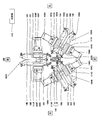
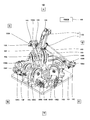
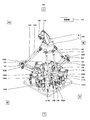
- FIG. 1 is a perspective view showing a schematic configuration of the operating device according to the first embodiment.
- FIG. 2 is a top view of the operating device shown in FIG.
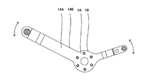
- FIG. 3 is a perspective view illustrating a schematic configuration of a pair of arm portions of the operating device illustrated in FIG. 1.
- FIG. 4 is a block diagram illustrating a schematic configuration of a robot system including the operation device according to the first embodiment.
- FIG. 5A is a schematic diagram illustrating a schematic configuration of a pair of arm portions of the operating device illustrated in FIG. 1.
- FIG. 5B is a schematic diagram illustrating a schematic configuration of a pair of arm portions of the operating device illustrated in FIG. 1.
- FIG. 6 is a perspective view illustrating a schematic configuration of the operating device according to the second modification of the first embodiment.
- FIG. 7 is a perspective view showing a schematic configuration of a main part of the parallel link mechanism in the operating device shown in FIG.
- FIG. 8 is a perspective view illustrating a schematic configuration of the operating device according to the third modification of the first embodiment.
- FIG. 9 is a perspective view showing a schematic configuration of a main part of the parallel link mechanism in the operating device shown in FIG.
- FIG. 10 is a top view showing a schematic configuration of a main part of the parallel link mechanism in the operating device shown in FIG.
- FIG. 11 is a side view showing a schematic configuration of a main part of the parallel link mechanism in the operating device shown in FIG.
- FIG. 12 is a schematic diagram showing a schematic configuration of a main part of the parallel link mechanism in the operating device shown in FIG. FIG.
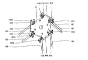
- FIG. 13 is a perspective view showing a schematic configuration of the operating device according to the second embodiment.
- 14 is a side view of the operating device shown in FIG.
- FIG. 15 is a perspective view showing a schematic configuration of a main part of the parallel link mechanism in the operating device shown in FIG.
- FIG. 16 is a perspective view illustrating a schematic configuration of a main part of the parallel link mechanism in the operating device illustrated in FIG. 13.
- FIG. 17 is a side view showing a schematic configuration of a main part of the parallel link mechanism in the operating device shown in FIG.
- FIG. 18 is a side view showing a schematic configuration in the vicinity of the movable portion in the operating device shown in FIG.
- FIG. 19 is a perspective view showing a schematic configuration in the vicinity of the movable portion in the operating device shown in FIG.
- FIG. 20 is a schematic diagram illustrating a schematic configuration of a main part of the operating device according to the third embodiment.
- the operating device includes a base portion, an operating portion that is disposed above the base portion, includes a movable portion and a gripped portion, a pair of arm portions, and a pair of link portions.
- a link mechanism ; a position sensor that detects the position of the base end of the arm unit; and a controller that controls the position and / or posture of the robot based on the position detected by the position sensor.
- the end portion is pivotally connected to the base portion, and the link portion has a base end portion pivotally connected to the arm portion and a distal end portion pivotally connected to the movable portion.
- the base portion and the movable portion are connected to each other by three sets of parallel link mechanisms.
- the pair of arm portions may be connected to each other by a first connection member having a predetermined first holding force set in advance.
- the pair of arm units when a load less than the first holding force is applied to the first connecting member by the operator operating the operating unit, the pair of arm units is one arm unit.
- the other arm portion is configured to move so as to follow the movement of the first arm.
- the pair of arm portions operate independently. It may be configured as follows.
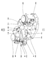
- FIG. 1 is a perspective view showing a schematic configuration of the operating device according to the first embodiment.
- FIG. 2 is a top view of the operating device shown in FIG.
- the vertical direction, the front-rear direction, and the left-right direction in the operating device are represented as the vertical direction, front-rear direction, and the left-right direction in the drawing. In FIG. It represents as the front-back direction and the left-right direction.
- the operating device 100 includes a base unit 101, an operating unit 102, parallel link mechanisms 103A to 103C, position sensors 104A to 104F, and a controller 110.
- the operator controls the position and / or posture of the robot 200 described later by operating the operation unit 102.
- the base unit 101 is formed in a substantially rectangular shape, and an operation unit 102 is disposed above the base unit 101.
- the base unit 101 and the operation unit 102 are connected by three sets of parallel link mechanisms 103A to 103C so as to have six degrees of freedom.
- the operation unit 102 includes a movable unit 11 and a gripped unit 12.
- the movable portion 11 is composed of a plate-like portion to which the upper ends of the parallel link mechanisms 103A to 103C are connected, and a columnar portion standing on the upper surface of the plate-like portion.
- the gripped portion 12 is a portion gripped by an operator, and is provided with various buttons 12A and 12B for operating the robot 200.
- the button 12A and / or the button 12B may function as a switch (trigger; switch) for switching between position control and posture control of the robot 200, for example.
- the gripped portion 12 is arranged so that its axis is inclined forward in the initial state (origin position). Thereby, when an operator hold
- the parallel link mechanisms 103A to 103C are arranged at equiangular intervals (120 ° intervals) when viewed from above.
- the parallel link mechanism 103A has a pair of arm portions 14A and 14B and a pair of link portions 15A and 15B.
- the parallel link mechanism 103B includes a pair of arm portions 14C and 14D and a pair of link portions 15C and 15D.
- the parallel link mechanism 103C includes a pair of arm portions 14E and 14F and a pair of link portions 15C and 15D. Link portions 15E and 15F.
- the link portion 15A has an upper end portion (tip portion) rotatably connected to the movable portion 11 of the operation portion 102 via the first joint 107A. Further, the lower end (base end portion) of the link portion 15A is rotatably connected to the outer side end portion 3A (tip end portion) of the arm portion 14A via the second joint 108A (see FIG. 3). ).
- the link portion 15B has an upper end portion (tip portion) that is rotatably connected to the movable portion 11 of the operation portion 102 via the first joint 107B.
- the link portion 15B has a lower end (base end portion) rotatably connected to an outer side end portion 3B (tip end portion) of the arm portion 14B via the second joint 108B (see FIG. 3). ).
- the first joints 107A and 107B and the second joints 108A and 108B may be various joints such as a universal joint or a ball joint, respectively.
- link portions 15C to 15F are configured in the same manner as the link portions 15A and 15B, and thus detailed description thereof is omitted.
- the base portion of the arm portion 14A is pivotally connected to the base portion 101 by an appropriate means via a substantially L-shaped support member 111A.
- the arm portion 14B has a base end portion rotatably connected to the base portion 101 by an appropriate means via a substantially L-shaped support member 111B.
- the base portions of the arm portions 14C to 14F are pivotally connected to the base portion 101 by appropriate means via substantially L-shaped support members 111C to 111F, respectively.
- the pair of arm portions 14A and 14B will be described in detail with reference to FIG. Since the arm portion 14B is configured in the same manner as the arm portion 14A, detailed description thereof is omitted. Further, the other pair of arm portions 14C to 14F are configured in the same manner as the arm portion 14A, and thus detailed description thereof is omitted.
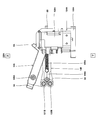
- FIG. 3 is a perspective view showing a schematic configuration of a pair of arm portions of the operating device shown in FIG.
- the arm portion 14A is formed in a substantially V shape, and the bent portion 1A constitutes the base end portion of the arm portion 14A.
- the bent portion 1A is provided with a through hole 2A.
- An output shaft of a driver (here, a servo motor) 106A is directly or indirectly fixed to the through hole 2A by an appropriate means (not shown).
- the output shaft of the driver 106A may be supported by a bearing member (for example, a bearing or the like) provided on the support member 111A.
- the driver 106A may be configured to drive the operation unit 102 so that the operation unit 102 is not pushed down from the origin position by the weight of the operation unit 102 or the like.
- the outer side end portion 3A of the arm portion 14A constitutes the tip portion of the arm portion 14A.
- the base end portion of the link portion 15A is rotatably connected to the outer side distal end 3A via the second joint 108A (see FIGS. 1 and 2).
- first connecting member 105A is rotatably connected to the inner side end 4A of the arm portion 14A by the first fastening member 5A.
- the other end of the first connecting member 105A is rotatably connected to the inner end 4B of the arm portion 14B by the first fastening member 5B.
- the first connecting member 105A connects the arm part 14A and the arm part 14B so as to be orthogonal to the extending direction of the arm part 14A when the operation part 102 is at the origin position. It is configured.
- the first fastening member 5A and the first fastening member 5B are composed of bolts and nuts here.
- the first connecting member 105A When a load less than a predetermined first holding force set in advance is applied, the first connecting member 105A operates such that one of the arm portions 14A and 14B follows the operation of the other arm portion. When a load greater than or equal to the first holding force is applied to the first connecting member 105A, the arm portion 14A and the arm portion 14B are configured to operate independently.
- the first connecting member 105A may be constituted by, for example, a tension spring. Further, the first connecting member 105A may be configured by, for example, drivers 106A and 106B. In this case, the arm part 14A and the arm part 14B are electrically connected.
- a torque sensor or the like is provided on the output shaft of the drivers 106A and 106B, and the controller 110 detects the torque value detected by the torque sensor. Then, it is determined whether or not a load greater than or equal to the first holding force is applied, and the drivers 106A and 106B are controlled based on the determination.
- the first holding force can be set in advance by experiments or the like.
- the first holding force may be 0.1 N ⁇ m to 1.0 N ⁇ m.
- a spring constant or the like may be set as appropriate so that the tension spring has a first holding force.
- the motor may be selected based on the weight of the operation unit 102, the load applied to the joint such as the first joint 107A, and the like.
- the support member 111A is provided with a position sensor 104A that detects the position of the base end portion (here, the bent portion 1A) of the arm portion 14A.
- the support member 111B is provided with a position sensor 104B that detects the position of the base end portion (here, the bent portion 1B) of the arm portion 14B.
- the support member 111C is provided with a position sensor 104C that detects the position of the base end portion of the arm portion 14C
- the support member 111D is a position sensor that detects the position of the base end portion of the arm portion 14D.
- 104D is provided.
- the support member 111E is provided with a position sensor 104E that detects the position of the base end portion of the arm portion 14E
- the support member 111F is a position sensor 104F that detects the position of the base end portion of the arm portion 14F. Is provided.
- the position sensors 104A to 104F are configured to detect the positions of the base end portions of the arm portions 14A to 14F, respectively, and output the detected position information to the controller 110.
- the position sensors 104A to 104F may be rotation sensors that detect the rotational positions of the base end portions of the arm portions 14A to 14F, for example. Examples of the rotation sensor include a rotary encoder, a potentiometer, or a laser sensor.
- the position sensors 104A to 104F may directly detect the rotational positions of the base end portions of the arm portions 14A to 14F, or may indirectly detect them.
- the position sensors 104A to 104F may detect the rotational positions of the output shafts of the drivers 106A to 106F as the respective rotational positions of the base end portions of the arm portions 14A to 14F.
- the position sensors 104A to 104F are converted into linear motions using, for example, a mechanism (ball screw or the like) that converts the rotational motions (rotational motions) of the arm portions 14A to 14F into linear motions (linear motions).
- a mechanism ball screw or the like
- the linear sensor include a linear encoder or a laser sensor.
- the controller 110 includes a calculation unit such as a microprocessor and a CPU, and a storage unit such as a ROM and a RAM (not shown). Information such as basic programs and various fixed data is stored in the storage unit.
- the calculation unit controls various operations of the robot 200 by reading and executing software such as a basic program stored in the storage unit.
- the controller 110 may be configured by a single controller 110 that performs centralized control, or may be configured by a plurality of controllers 110 that perform distributed control in cooperation with each other.
- the controller 110 may be configured by a microcomputer, and may be configured by an MPU, a PLC (Programmable Logic Controller), a logic circuit, or the like.
- FIG. 4 is a block diagram illustrating a schematic configuration of a robot system including the operation device according to the first embodiment.
- the robot system 300 including the operation device according to the first embodiment includes the operation device 100 and the robot 200.
- the robot 200 may be a horizontal articulated double-arm robot, or may be another robot such as a horizontal articulated type or a vertical articulated type.
- the robot 200 has a driver 201 for relatively driving each joint.
- the driver 201 is configured to drive based on the position and / or orientation command value of the robot 200 output from the controller 110.
- the driver 201 may be a servo motor, for example.
- the robot 200 may have a force sensor 202.
- the force sensor 202 is configured to detect a reaction force acting on the end effector or the like from the outside, or a force acting on the outside of the end effector or the like, and output the detected force information to the controller 110. Then, the controller 110 may execute haptic control in which force information detected by the force sensor 202 is fed back to the drivers 106A to 106F. Further, the controller 110 may control the operation device 100 and the robot 200 bilaterally.
- FIG. 5A and 5B are schematic views showing a schematic configuration of a pair of arm portions of the operating device shown in FIG. 1, and FIG. 5A shows a state in which a load less than the first holding force is applied to the first connecting member. FIG. 5B shows a state in which a load greater than or equal to the first holding force is applied to the first connection member.
- the movable unit 11 moves up and down, back and forth, and left and right. Along with this, the link portions 15A to 15F and the arm portions 14A to 14F rotate (swing).
- the arm portions 14A and 14B are moved by the elastic force of the first connecting member 105A.
- the other arm portion operates (swings) so as to follow the operation (swing).
- the arm portions 14C and 14D follow the operation (swing) of one arm portion by the elastic force of the first connecting member 105B.
- the other arm portion operates.
- the arm portions 14E and 14F follow the operation (swing) of one arm portion by the elastic force of the first connecting member 105C.
- the other arm part operates (swings).
- the movable unit 11 of the operation unit 102 moves in the vertical direction, the front-rear direction, and the horizontal direction while maintaining a horizontal state. Therefore, the control command value output from the controller 110 is a command value for changing the position information of the robot 200, and the robot 200 can maintain the posture state immediately before the operator operates the operation unit 102. That is, the operator operates the operation unit 102 so that a load less than the first holding force is applied to the first connection members 105A to 105C (so that the movable unit 11 maintains a horizontal state). Can be manipulated to change position.
- the arm portions 14A and 14B operate (swing) independently.
- the arm portions 14C and 14D each operate (swing) independently.
- the arm portions 14E and 14F operate (swing) independently.
- the movable unit 11 of the operation unit 102 is inclined in an arbitrary direction, and is moved in the vertical direction, the front-rear direction, and the horizontal direction while being inclined.
- the control command value output from the controller 110 becomes the posture information of the robot 200 or the posture information and position information of the robot 200, and the posture of the robot 200 or the posture and position of the robot 200 can be changed.
- the operator operates the operation unit 102 so that at least one of the first connection members 105A to 105C is loaded with a load greater than or equal to the first holding force, so that the robot 200 The position or the position and posture of the robot 200 can be changed.
- each of the link portions 15A to 15F constituting the parallel link mechanisms 103A to 103C is rotatably connected to one movable portion 11. Yes. For this reason, compared with the parallel manipulator currently disclosed by the said patent document 1, compactization can be achieved.
- the axis is disposed so as to tilt forward.
- the first connecting member is disposed on the pair of arm portions.
- the operator can operate to change the position of the robot 200 by operating the operation unit 102 so that a load less than the first holding force is applied to the first connection members 105A to 105C. .
- the operator operates the operation unit 102 so that at least one of the first connection members 105A to 105C is loaded with a load greater than or equal to the first holding force.
- the position or the position and posture of the robot 200 can be changed.
- the operator can switch between position control and posture control of the robot 200 by changing the load applied to the first connecting member.
- the configuration in which the drivers 106A to 106F are provided is adopted, but the present invention is not limited to this.
- the drivers 106A to 106F a mode in which one or more drivers are not provided may be adopted.
- the operating device is further provided with a driver that is provided at the base end portion of the arm unit and drives the arm unit, and the controller performs the position control of the robot.
- a driver for driving the other arm portion is driven so as to follow the operation of the one arm portion.
- the operating device of the first modification may further include a switch for switching between position control and posture control of the robot.
- the operating device 100 according to the first modification has the same configuration as the operating device 100 according to the first embodiment, and thus detailed description thereof is omitted.
- the button 12A and / or the button 12B function as a switch for switching between position control and posture control of the robot 200.
- the position control of the robot 200 is executed when the operator operates (presses) the button 12A, and the posture control (posture control) of the robot 200 is performed by operating (pressing) the button 12B. And position control) are executed.
- At least one or more first connection members among the first connection members 105A to 105C may not be provided.
- the controller 110 operates (swings) one arm unit in the pair of arm units.
- the driver that drives the other arm is controlled so as to follow the movement).
- the controller 110 acquires position information (for example, rotation angle) of the base end portion of one arm portion from the position sensor, and drives to drive the other arm portion based on the position information. Control the instrument.
- the controller 110 when the operator operates (presses) the button 12B and operates the operation unit 102 in order to execute the posture control of the robot 200, the controller 110 includes a pair of arm units, and each arm unit is independent. Thus, the driver is controlled so as to operate (oscillate). At this time, the controller 110 may control the driver so that the operator does not feel a load. The controller 110 may perform haptic control in which force information detected by the force sensor 202 is fed back to the drivers 106A to 106F. Further, the controller 110 may control the operation device 100 and the robot 200 bilaterally.
- the position control and the posture control of the robot 200 can be switched by the button 12A and the button 12B, so that the robot 200 can be easily operated.
- the position control and the posture control of the robot 200 are switched using the button 12A and the button 12B.
- the present invention is not limited to this.
- a mode in which the position control and posture control of the robot 200 are switched by the button 12A may be employed, or a mode in which the switching is performed by the button 12B may be employed.
- the position control and the posture control of the robot 200 may be switched between when the button is pressed once and when the button is pressed twice continuously.
- FIG. 6 is a perspective view illustrating a schematic configuration of the operating device according to the second modification of the first embodiment.
- FIG. 7 is a perspective view showing a schematic configuration of a main part of the parallel link mechanism in the operating device shown in FIG.
- the operating device 100 according to the second modification of the first embodiment has the same basic configuration as that of the operating device 100 according to the first embodiment.
- the difference is that the pivot shaft of the proximal end portion and the output shaft of the driver are connected by a belt drive and the first connecting member is provided at the distal end portion of the arm portion.
- the configuration of the parallel link mechanism 103A will be described with reference to FIG. Since the parallel link mechanisms 103B and 103C are configured in the same manner as the parallel link mechanism 103A, detailed description thereof is omitted. Moreover, since the arm part 14B is comprised similarly to 14A of arm parts, the detailed description is abbreviate
- the arm portion 14A is formed in a rod shape, and one end of the first connection member 105A is connected to the outer side end portion (tip portion) 3A via the first fastening member 5A.
- the other end of the first connecting member 105A is rotatably connected to the outer side end portion (tip portion) 3B of the arm portion 14B by the first fastening member 5B. More specifically, the first connecting member 105A connects the arm part 14A and the arm part 14B so as to be orthogonal to the extending direction of the arm part 14A when the operation part 102 is at the origin position. It is configured.
- first pulley 141A is fitted in the middle of the bolt 131A, and the tip thereof is rotatably provided at the upper end of the support member 112A via the bearing member 132A. That is, the bolt 131A constitutes the rotation shaft of the base end portion of the arm portion 14A, and the arm portion 14A and the first pulley 141A are connected so that the first pulley 141A rotates as the arm portion 14A rotates. Connected.
- the support member 111A and the support member 112A are erected on the upper surface of the substrate 120A disposed on the upper surface of the base portion 101.
- the first pulley 141A is disposed so as to be sandwiched between the support member 111A and the support member 112A.
- a second pulley having a smaller radius than the first pulley 141A is disposed below the first pulley 141A (not shown).
- the output shaft of the driver 106A is connected to the second pulley via appropriate means (for example, a bearing or the like).
- a belt 143A is hung on the outer peripheral surfaces of the first pulley 141A and the second pulley.
- the rotation operation of the arm portion 14A is transmitted to the output shaft of the driver 106A by the belt drive 140A including the first pulley 141A, the belt 143A, and the second pulley.
- FIG. 8 is a perspective view illustrating a schematic configuration of the operating device according to the third modification of the first embodiment.
- FIG. 9 is a perspective view showing a schematic configuration of a main part of the parallel link mechanism in the operating device shown in FIG.
- FIG. 10 is a top view showing a schematic configuration of a main part of the parallel link mechanism in the operating device shown in FIG.
- FIG. 11 is a side view showing a schematic configuration of a main part of the parallel link mechanism in the operating device shown in FIG.
- FIG. 12 is a schematic diagram showing a schematic configuration of a main part of the parallel link mechanism in the operating device shown in FIG.
- the vertical direction, the front-rear direction, and the left-right direction in the operating device are represented as the vertical direction, the front-rear direction, and the left-right direction in the drawing, and in FIGS. It represents as the up-down direction in a figure.
- the operating device 100 according to the third modification of the first embodiment has the same basic configuration as the operating device 100 according to the first embodiment, but forms a parallel link mechanism.
- the pivot shaft of the base end portion of the arm portion and the output shaft of the driver are connected by the hypoid gear and the belt drive, and the first connecting member is arranged in the extending direction of the arm portion, Is different.
- the configuration of the parallel link mechanism 103A will be described with reference to FIGS. Since the parallel link mechanisms 103B and 103C are configured in the same manner as the parallel link mechanism 103A, detailed description thereof is omitted.
- the arm portion 14A is formed in a rod shape, and the inner side end portion (base end portion) 4A has a substantially L-shaped support member 111A via a bearing member 130A. Is pivotably connected to the upper end of the.
- the arm portion 14B is formed in a rod shape, and the inner side end portion (base end portion) 4B is rotatable to the upper end portion of the substantially L-shaped support member 111B via the bearing member 130B. It is connected to the.
- a through hole is provided in the inner side end portion 4A of the arm portion 14A, and a base end portion of a bolt 131A into which the bearing member 130A is inserted is fitted in the through hole.
- a hypoid gear 151A is fitted to the tip of the bolt 131A.
- the hypoid gear 151A is formed in a substantially disc shape, and teeth are arranged in an annular shape.
- a bearing member 130A is disposed on the outer peripheral surface of the hypoid gear 151A and supports the hypoid gear 151A.
- a hypoid opinion 152A is meshed with the hypoid gear 151A.
- the hypoid opinion 152A has a shaft portion pivotally supported by the bearing member 132A, and a base end portion of the hypoid opinion 152A is fitted to the first pulley 141A.
- a second pulley 142A is disposed outside the first pulley 141A.
- the output shaft 26A of the driver 106A is connected to the second pulley 142A via appropriate means (for example, a bearing or the like).
- a belt 143A is hung on the outer peripheral surfaces of the first pulley 141A and the second pulley. Thereby, the rotation operation of the arm portion 14A is transmitted to the output shaft 26A of the driver 106A.
- the driver 106A has a housing 36A, a driver main body 16A, and an output shaft 26A, and the driver main body 16A and the output shaft 26A are arranged in the housing 36A.
- the driver main body 16A may be, for example, a rotor and a stator of a servo motor.
- a position sensor 104A is disposed in the housing 36A.
- the position sensor 104A detects the rotational position of the output shaft 26A of the driver 106A, and outputs the detected rotational position information to the controller 110. Yes.
- connection aspect of the inner side edge part 4B of the arm part 14B and the output shaft of the driver 106B is comprised similarly to the inner side edge part 4A of the arm part 14A, and the output shaft 26A of the driver 106A. Therefore, the detailed description is abbreviate
- a stopper 6A is provided on the upper part of the inner side end portion 4A of the arm portion 14A.
- the stopper 6A is configured to regulate the swing range of the arm portion 14B when the arm portion 14A and the arm portion 14B swing independently.
- first connecting member 105A is connected to the base end 7B of the arm portion 14B via the first fastening member 5B.
- a wire 109A is connected to the other end of the first connecting member 105A.
- the wire 109A is disposed so as to pass between a pair of pulleys 121B and 122B provided at the outer side end (tip portion) 3B of the arm portion 14B. Further, the distal end portion of the wire 109A is fixed to the outer end portion 3A of the arm portion 14A. That is, in the third modification, the first connecting member 105A is arranged along the extending direction of the arm portion 14A.
- the arm portion 14A and the arm portion 14B are configured so that the other arm portion follows the operation (swing) of the one arm portion. Operates (oscillates). Further, when a load greater than or equal to the first holding force is applied to the first connecting member 105A, the arm portion 14A and the arm portion 14B operate (swing) independently of each other.
- the first connecting member 105A is arranged along the extending direction of the arm portion 14A. Therefore, the first connecting member 105A is disposed between the arm portion 14A and the arm portion 14B as compared with the operating device 100 according to Embodiment 1 in which the first connecting member 105A is arranged to bridge the arm portion 14A and the arm portion 14B. A distance can be made small and the operating device 100 can be made more compact.
- the displacement amount (angle difference) is transmitted via the pulleys 121B and 122B.
- the amount of change on a straight line is converted.
- the expansion / contraction direction of the first connection member 105A matches the linear direction (the direction of stress applied to the first connection member 105A) converted by the pulleys 121B and 122B.
- the first connecting member 105A is arranged.
- the arm part 14A and the arm part 14B can be operated more sensitively to the load applied to the first connecting member 105A.
- the operating device according to the second embodiment is the operating device according to the first embodiment (including the modified example), and the reversal suppression member configured to suppress the reversal of the link portion is provided in the movable portion. ing.
- one arm portion of the pair of arm portions is provided with a roller portion, and the other arm portion is configured such that the roller portion moves.
- a roller guide portion may be provided.
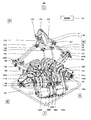
- FIG. 13 is a perspective view showing a schematic configuration of the operating device according to the second embodiment.
- 14 is a side view of the operating device shown in FIG.
- FIG. 15 is a perspective view showing a schematic configuration of a main part of the parallel link mechanism in the operating device shown in FIG.
- FIG. 16 is a perspective view illustrating a schematic configuration of a main part of the parallel link mechanism in the operating device illustrated in FIG. 13.
- FIG. 17 is a side view showing a schematic configuration of a main part of the parallel link mechanism in the operating device shown in FIG.
- the vertical direction, the front-rear direction, and the left-right direction in the operating device are represented as the vertical direction, the front-rear direction, and the left-right direction in the drawing.
- FIG. It represents as the up-down direction and the front-back direction.
- FIG. 17 a part of the front arm portion in the drawing is omitted.
- the operating device 100 according to the second embodiment has the same basic configuration as the operating device 100 according to the first embodiment, but a reversal suppression member is provided in the movable portion 11.
- the difference is that the rotation shaft of the base end portion of the arm portion constituting the parallel link mechanism and the output shaft of the driver are connected by a belt drive.
- the first connecting member is arranged in the extending direction of the arm portion, and one arm of the pair of arm portions.
- the part is provided with a roller part
- the other arm part is provided with a roller guide part configured to move the roller part.
- the configuration of the parallel link mechanism 103A will be described with reference to FIGS. Since the parallel link mechanisms 103B and 103C are configured in the same manner as the parallel link mechanism 103A, detailed description thereof is omitted.
- the rotation shaft of the inner side end (base end) 4A of the arm portion 14A, the output shaft of the driver 106A, and are connected by a belt drive 140A.
- the arm portion 14A and the belt drive 140A are arranged so as to be sandwiched between the support member 111A and the support member 112A, whereas in the second embodiment, the arm The difference is that the portion 14A and the belt drive 140A are arranged so as to sandwich the support member 111A and the support member 112A.
- the arm portion 14A is connected to the first pulley 141A by a first shaft member 161A.
- one end of the first shaft member 161A is fitted into a through hole 2A (see FIGS. 15 to 17) provided in the inner side end 4A of the arm portion 14A by an appropriate means.
- the other end of the first shaft member 161A is fitted to the first pulley 141A by an appropriate means.
- the first shaft member 161A is disposed so as to be fitted with a bearing member provided at each upper end portion of the support member 111A and the support member 112A.
- the first pulley 141A can rotate as the arm portion 14A rotates. That is, the first shaft member 161A constitutes the rotation shaft of the arm portion 14A.
- a second pulley 142A having a smaller radius than the first pulley 141A is disposed below the first pulley 141A.
- the output shaft of the driver 106A is connected to the second pulley 142A via the second shaft member 162A.
- a belt 143A is hung on the outer peripheral surfaces of the first pulley 141A and the second pulley 142A.
- the rotation operation of the arm portion 14A is transmitted to the output shaft of the driver 106A by the belt drive 140A including the first pulley 141A, the belt 143A, and the second pulley.
- the pair of arm portions 14C and 14D constituting the parallel link mechanism 103B and the pair of arm portions 14E and 14F constituting the parallel link mechanism 103C are configured similarly to the pair of arm portions 14A and 14B. Therefore, the detailed description is abbreviate
- the arm portion 14A is formed in a substantially T-shape, and the inner side end portion (base end portion) 4A is connected to the outer side end portion (tip end portion) 3A.
- a counterweight 9A for balancing the weight is provided.
- a through hole 2A is provided at an appropriate position on the tip side of the counterweight 9A of the inner side end 4A. As described above, one end of the first shaft member 161A (not shown in FIGS. 15 to 17) is fitted into the through hole 2A.
- the arm portion 14B is formed in a substantially T shape, and the inner side end portion (base end portion) 4B has a weight balance with respect to the outer side end portion (tip end portion) 3B.
- Counterweight 9B is provided.
- a through hole 2B is provided at an appropriate position on the tip end side of the counterweight 9B of the inner end 4B.
- One end of a first shaft member (not shown) is fitted in the through hole 2B.
- a stopper 6A is provided on the upper end side of the arm portion 14A from the through hole 2A.
- the stopper 6A is configured to regulate the swing range of the arm portion 14B when the arm portion 14A and the arm portion 14B swing independently.
- one end of the first connecting member 105A is connected to the inner side end 4B of the arm portion 14B via the first fastening member 5B.
- a wire 109A is connected to the other end of the first connecting member 105A.
- the wire 109A is disposed so as to pass between a pair of pulleys 121B and 122B provided at the outer side end (tip portion) 3B of the arm portion 14B. Further, the distal end portion of the wire 109A is fixed to the outer end portion 3A of the arm portion 14A. That is, in the second embodiment, the first connecting member 105A is arranged along the extending direction of the arm portion 14A.
- roller portions 171B and 172B are arranged at appropriate positions on the proximal end side with respect to the pulley 121B of the inner side end portion 4B of the arm portion 14B. More specifically, the roller portions 171B and 172B are disposed on the side surface of the arm portion 14B facing the arm portion 14A.
- a roller guide portion 173A is provided at a portion facing the roller portions 171B and 172B of the arm portion 14A so as to extend in the vertical direction.
- the roller guide portion 173A may be provided with step portions 174A and 175A.
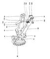
- FIG. 18 is a side view showing a schematic configuration in the vicinity of the movable part in the operating device shown in FIG.
- FIG. 19 is a perspective view showing a schematic configuration in the vicinity of the movable portion in the operating device shown in FIG. In FIG. 18 and FIG. 19, the description of the gripped portion of the operation unit is omitted.
- the movable portion 11 is formed in a substantially disc shape, and plate-like projections 41A to 41C are provided on the side surfaces thereof so as to protrude in three directions, respectively. It has been.
- a link portion 15A is rotatably connected to the central portion of one side wall of the protruding portion 41A via a first joint 107A. Further, a link portion 15B is rotatably connected to the central portion of the other side wall of the protruding portion 41A via the first joint 107B.
- a rod-like reversal suppression member 51A is provided at the tip of one side wall of the protrusion 41A, and a rod-like reversal suppression member 51B is provided at the tip of the other side wall of the protrusion 41A. Yes.
- the reversal suppressing member 51A is configured to suppress the reversal of the link portion 15A by coming into contact with the link portion 15A.
- the inversion suppression member 51B is configured to suppress inversion of the link portion 15B by coming into contact with the link portion 15B.
- the fact that the link portion is reversed means that the angle formed between the link portion and the movable portion 11 is larger than 180 ° by the rotation of the link portion.
- the to-be-gripped part 12 exists in an initial state (origin position), suppose that the angle which a link part and the movable part 11 make is 180 degrees or less.
- link portions 15C and 15D are rotatably connected to the center portions of both side walls of the protrusion portion 41B via first joints 107C and 107D, respectively.
- Bar-shaped reversal suppression members 51C and 51D are provided at the front ends of both side walls of the protrusion 41B.
- link portions 15E and 15F are rotatably connected to the central portions of both side walls of the protruding portion 41C via first joints 107E and 107F, respectively.
- Bar-shaped inversion suppression members 51E and 51F are provided at the tip portions of both side walls of the protrusion 41C.
- the form in which the reversal suppression members 51A to 51F are provided for the link portions 15A to 15F is adopted, but the present invention is not limited to this.
- the link portions 15A to 15F at least one link portion may be provided with an inversion suppression member, and any of the link portions may not be provided with an inversion suppression member. .
- the arm portion 14B is provided with roller portions 171B and 172B, and the arm portion 14A is configured such that the roller portions 171B and 172B move.
- a guide portion 173A is provided.
- roller guide portion 173A is provided with step portions 174A and 175A
- the roller portions 171B and 172B have the step portions 174A and 174A so that the arm portion 14B swings independently of the arm portion 14A. You have to get over 175A. For this reason, compared with the case where step part 174A, 175A is not provided, a 1st holding force can be made small.
- the movable portion 11 is provided with reversal suppression members 51A to 51F for the link portions 15A to 15F, respectively.
- the operating device according to the third embodiment further includes a second connecting member that connects the arm portion and the base portion in the operating device according to the first embodiment (including the modification) or the second embodiment.
- FIG. 20 is a schematic diagram illustrating a schematic configuration of a main part of the operating device according to the third embodiment.
- the operating device 100 according to the third embodiment has the same basic configuration as the operating device 100 according to the first embodiment, but the second connecting the arm unit and the base unit 101. The difference is that a connecting member is provided.
- one end of the second connection member 113A is pivotally connected to the inner side end 4A of the arm portion 14A via the first fastening member 5A, and the other end is connected to the base. It is pivotally connected to an appropriate position of the portion 101 via the second fastening member 8A.
- connection member 113B has one end rotatably connected to the inner side end 4B of the arm portion 14B via the first fastening member 5B, and the other end connected to the base portion 101. Is pivotally connected to the appropriate position via the second fastening member 8B.
- the second connection member is provided similarly to the arm portions 14A and 14B.
- the second connecting member is configured so that the operation unit 102 is not pushed down from the origin position due to the weight of the operation unit 102 or the like.
- the second connection member may be constituted by a tension spring.
- a spring constant or the like is appropriately set so that the operation unit 102 is not pushed down from the origin position due to the weight of the operation unit 102 or the like.
- the tension spring may be configured to be elastically deformed when a load greater than or equal to the first holding force is applied. If comprised in this way, the said tension
- the second connecting member may be constituted by a driver.
- the driver is driven by the controller 110 so that the operation unit 102 is not pushed down from the origin position by the weight of the operation unit 102 or the like.
- a torque sensor or the like may be provided on the output shaft of the driver.
- the controller 110 determines that a load less than the first holding force is applied based on the torque value detected by the torque sensor, the controller 110 follows the operation of one arm portion in the pair of arm portions. Then, the driver is driven so that the other arm portion operates.
- the controller 110 determines that a load equal to or greater than the first holding force is applied, the controller 110 drives the driver so that the pair of arm portions operate independently.
- the driver can also function as the first connecting member.
- the operating device of the present invention can be made more compact than a conventional operating device, and thus is useful in the field of industrial robots.
Landscapes
- Engineering & Computer Science (AREA)
- Physics & Mathematics (AREA)
- General Physics & Mathematics (AREA)
- Automation & Control Theory (AREA)
- Mechanical Engineering (AREA)
- Robotics (AREA)
- General Engineering & Computer Science (AREA)
- Manipulator (AREA)
- Transmission Devices (AREA)
- Mechanical Control Devices (AREA)
Abstract
ベース部(101)と、ベース部(101)の上方に配置され、可動部(11)と被把持部(12)を有する操作部(102)と、一対のアーム部と、一対のリンク部と、を有するパラレルリンク機構と、アーム部の基端部の位置を検知する位置センサと、位置センサが検知した位置に基づき、ロボットの位置及び/又は姿勢を制御する制御器(110)と、を備え、アーム部は、基端部がベース部(101)に回動自在に接続されていて、リンク部は、基端部がアーム部に回動自在に接続され、先端部が可動部(11)に回動自在に接続されていて、6自由度を有するように、3組のパラレルリンク機構(103A~103C)により、ベース部(101)と可動部(11)との間が連結されている、操作装置。
Description
本発明は、操作装置に関する。
6自由度で動作できるパラレルマニピュレータが知られている(例えば、特許文献1参照)。特許文献1に開示されているパラレルマニピュレータでは、操作しようとする対象物を支持するための端部プラットフォームと端部プラットフォームから離隔して配置され、連結要素によって端部プラットフォームに連結された中間プラットフォームを含む。複数の第1リンクが端部プラットフォームに連結され、複数の第2リンクが中間プラットフォームに連結されている。
そして、特許文献1に開示されているパラレルマニピュレータでは、端部プラットフォームに取り付けられたハンドルを使用者が握ることができ、使用者は端部プラットフォームをジョイスティックのように操作すると記載されている。
しかしながら、上記特許文献1に開示されているパラレルマニピュレータでは、第1リンクが端部プラットフォームに連結され、第2リンクが中間プラットフォームに連結されている。すなわち、第1リンクと第2リンクが異なるプラットフォームに連結されているため、装置が大型化するという課題があった。
本発明は、上記従来の課題を解決するもので、従来の操作装置に比して、コンパクトにすることができる、操作装置を提供することを目的とする。
上記従来の課題を解決するために、本発明に係る操作装置は、ベース部と、前記ベース部の上方に配置され、可動部と被把持部を有する操作部と、一対のアーム部と、一対のリンク部と、を有するパラレルリンク機構と、前記アーム部の基端部の位置を検知する位置センサと、前記位置センサが検知した位置に基づき、ロボットの位置及び/又は姿勢を制御する制御器と、を備え、前記アーム部は、基端部が前記ベース部に回動自在に接続されていて、前記リンク部は、基端部が前記アーム部に回動自在に接続され、先端部が前記可動部に回動自在に接続されていて、6自由度を有するように、3組の前記パラレルリンク機構により、前記ベース部と前記可動部との間が連結されている。
これにより、従来の操作装置に比して、コンパクトにすることができる。
本発明の操作装置によれば、従来の操作装置に比して、コンパクトにすることができる。
以下、本発明の実施の形態を、図面を参照しながら説明する。なお、全ての図面において、同一又は相当部分には同一符号を付し、重複する説明は省略する。また、全ての図面において、本発明を説明するための構成要素を抜粋して図示しており、その他の構成要素については図示を省略している場合がある。さらに、本発明は以下の実施の形態に限定されない。
(実施の形態1)
本実施の形態1に係る操作装置は、ベース部と、ベース部の上方に配置され、可動部と被把持部を有する操作部と、一対のアーム部と、一対のリンク部と、を有するパラレルリンク機構と、アーム部の基端部の位置を検知する位置センサと、位置センサが検知した位置に基づき、ロボットの位置及び/又は姿勢を制御する制御器と、を備え、アーム部は、基端部がベース部に回動自在に接続されていて、リンク部は、基端部がアーム部に回動自在に接続され、先端部が可動部に回動自在に接続されていて、6自由度を有するように、3組のパラレルリンク機構により、ベース部と可動部との間が連結されている。
本実施の形態1に係る操作装置は、ベース部と、ベース部の上方に配置され、可動部と被把持部を有する操作部と、一対のアーム部と、一対のリンク部と、を有するパラレルリンク機構と、アーム部の基端部の位置を検知する位置センサと、位置センサが検知した位置に基づき、ロボットの位置及び/又は姿勢を制御する制御器と、を備え、アーム部は、基端部がベース部に回動自在に接続されていて、リンク部は、基端部がアーム部に回動自在に接続され、先端部が可動部に回動自在に接続されていて、6自由度を有するように、3組のパラレルリンク機構により、ベース部と可動部との間が連結されている。
また、本実施の形態1に係る操作装置では、一対のアーム部は、予め設定されている所定の第1保持力を有する第1接続部材により、互いに接続されていてもよい。
また、本実施の形態1に係る操作装置では、操作者が操作部を操作することにより、第1接続部材に第1保持力未満の荷重がかかると、一対のアーム部は、一方のアーム部の動作に追随するように他方のアーム部が動作するように構成されていて、第1接続部材に第1保持力以上の荷重がかかると、一対のアーム部は、それぞれ、独立して動作するように構成されていてもよい。
以下、本実施の形態1に係る操作装置の一例について、図1~図5Bを参照しながら説明する。
[操作装置の構成]
図1は、本実施の形態1に係る操作装置の概略構成を示す斜視図である。図2は、図1に示す操作装置の上面図である。なお、図1においては、操作装置における上下方向、前後方向、及び左右方向を図における上下方向、前後方向、及び左右方向として表し、図2においては、操作装置における前後方向及び左右方向を図における前後方向及び左右方向として表している。
図1は、本実施の形態1に係る操作装置の概略構成を示す斜視図である。図2は、図1に示す操作装置の上面図である。なお、図1においては、操作装置における上下方向、前後方向、及び左右方向を図における上下方向、前後方向、及び左右方向として表し、図2においては、操作装置における前後方向及び左右方向を図における前後方向及び左右方向として表している。
図1及び図2に示すように、本実施の形態1に係る操作装置100は、ベース部101、操作部102、パラレルリンク機構103A~103C、位置センサ104A~104F、及び制御器110を備えていて、操作者が、操作部102を操作することにより、後述するロボット200の位置及び/又は姿勢を制御する。
ベース部101は、略矩形に形成されていて、その上方には、操作部102が配置されている。ベース部101と操作部102は、6自由度を有するように、3組のパラレルリンク機構103A~103Cにより連結されている。
操作部102は、可動部11と被把持部12を有している。可動部11は、パラレルリンク機構103A~103Cの上端が接続されている板状部と、当該板状部の上面に立設されている円柱部と、から構成されている。可動部11の円柱部の上面には、略円柱状の被把持部12が立設されている。被把持部12は、操作者が把持する部分であり、ロボット200を操作するための各種のボタン12A、12Bが設けられている。ボタン12A及び/又はボタン12Bは、例えば、ロボット200の位置制御と姿勢制御とを切り替えるためのスイッチ(トリガー;切替器)として機能してもよい。
なお、本実施の形態1においては、被把持部12は、初期状態(原点位置)において、その軸心が、前方に傾くように、配置されている。これにより、操作者が被把持部12を把持したときに、操作者の手首に余計な力がかかることを抑制することができる。
パラレルリンク機構103A~103Cは、上方から見て、等角度間隔(120°間隔)で配置されている。パラレルリンク機構103Aは、一対のアーム部14A、14Bと、一対のリンク部15A、15Bと、を有している。同様に、パラレルリンク機構103Bは、一対のアーム部14C、14Dと、一対のリンク部15C、15Dと、を有していて、パラレルリンク機構103Cは、一対のアーム部14E、14Fと、一対のリンク部15E、15Fと、を有している。
リンク部15Aは、上端部(先端部)が、第1ジョイント107Aを介して、操作部102の可動部11に回動自在に接続されている。また、リンク部15Aは、下端(基端部)が、第2ジョイント108Aを介して、アーム部14Aの外方側端部3A(先端部)に回動自在に接続されている(図3参照)。
同様に、リンク部15Bは、上端部(先端部)が、第1ジョイント107Bを介して、操作部102の可動部11に回動自在に接続されている。また、リンク部15Bは、下端(基端部)が、第2ジョイント108Bを介して、アーム部14Bの外方側端部3B(先端部)に回動自在に接続されている(図3参照)。
第1ジョイント107A、107B、及び第2ジョイント108A、108Bは、それぞれ、ユニバーサルジョイント又はボールジョイント等の各種のジョイントを用いてもよい。
なお、リンク部15C~15Fについては、リンク部15A、15Bと同様に、構成されているため、その詳細な説明は省略する。
アーム部14Aは、基端部が、略L字状の支持部材111Aを介して、適宜な手段により、ベース部101に回動自在に接続されている。また、アーム部14Bは、基端部が、略L字状の支持部材111Bを介して、適宜な手段により、ベース部101に回動自在に接続されている。同様に、アーム部14C~14Fは、それぞれ、基端部が、略L字状の支持部材111C~111Fを介して、適宜な手段により、ベース部101に回動自在に接続されている。
ここで、図3を参照しながら、一対のアーム部14A、14Bについて、詳細に説明する。なお、アーム部14Bについては、アーム部14Aと同様に構成されているため、その詳細な説明を省略する。また、他の一対のアーム部14C~14Fについても、アーム部14Aと同様に構成されているため、その詳細な説明を省略する。
図3は、図1に示す操作装置の一対のアーム部の概略構成を示す斜視図である。
図3に示すように、アーム部14Aは、略V字状に形成されていて、その屈曲部分1Aがアーム部14Aの基端部を構成する。また、屈曲部分1Aには、貫通孔2Aが設けられている。貫通孔2Aには、駆動器(ここでは、サーボモータ)106Aの出力軸が、適宜な手段により、直接又は間接的に固定されている(図示せず)。
なお、駆動器106Aの出力軸は、支持部材111Aに設けられた軸受部材(例えば、ベアリング等)により、支持されていてもよい。また、駆動器106Aは、操作部102等の重量により、操作部102が原点位置から押し下がらないように駆動するように構成されていてもよい。
また、アーム部14Aの外方側端部3Aが、アーム部14Aの先端部を構成する。外方側先端3Aには、上述したように第2ジョイント108Aを介して、リンク部15Aの基端部が回動自在に接続されている(図1及び図2参照)。
さらに、アーム部14Aの内方側端部4Aには、第1接続部材105Aの一端が、第1締結部材5Aにより、回動自在に接続されている。第1接続部材105Aの他端は、第1締結部材5Bにより、アーム部14Bの内方側端部4Bに、回動自在に接続されている。より詳細には、第1接続部材105Aは、操作部102が原点位置にあるときに、アーム部14Aの延伸方向に対して、直交するように、アーム部14Aとアーム部14Bを接続するように構成されている。なお、第1締結部材5A及び第1締結部材5Bは、ここでは、ボルトとナットで構成されている。
第1接続部材105Aは、予め設定されている所定の第1保持力未満の荷重がかかるとアーム部14A、14Bのうち、一方のアーム部の動作に他方のアーム部が追随するように動作し、第1接続部材105Aに第1保持力以上の荷重がかかると、アーム部14Aとアーム部14Bは、それぞれ、独立して動作するように構成されている。
第1接続部材105Aとしては、例えば、引っ張りばねで構成されていてもよい。また、第1接続部材105Aとしては、例えば、駆動器106A、106Bで構成されていてもよい。この場合、アーム部14Aとアーム部14Bは、電気的に接続されていることになる。そして、第1接続部材105Aを駆動器106A、106Bで構成する場合には、駆動器106A、106Bの出力軸にトルクセンサ等を設けて、制御器110が、トルクセンサが検知したトルク値等により、第1保持力以上の荷重がかかったか否かを判断し、当該判断に基づき、駆動器106A、106Bを制御する。
また、第1保持力は、予め実験等により設定することができる。具体的には、第1保持力は、0.1N・m~1.0N・mであってもよい。そして、第1接続部材105Aを引っ張りばねで構成する場合には、引っ張りばねが第1保持力を有するように、ばね定数等を適宜設定すればよい。また、第1接続部材105Aを駆動器106A、106Bで構成する場合には、操作部102の重量、第1ジョイント107A等のジョイントにかかる荷重等から、モータを選定すればよい。
また、図1及び図2に示すように、支持部材111Aには、アーム部14Aの基端部(ここでは、屈曲部分1A)の位置を検知する位置センサ104Aが設けられている。また、支持部材111Bには、アーム部14Bの基端部(ここでは、屈曲部分1B)の位置を検知する位置センサ104Bが設けられている。
同様に、支持部材111Cには、アーム部14Cの基端部の位置を検知する位置センサ104Cが設けられていて、支持部材111Dには、アーム部14Dの基端部の位置を検知する位置センサ104Dが設けられている。また、支持部材111Eには、アーム部14Eの基端部の位置を検知する位置センサ104Eが設けられていて、支持部材111Fには、アーム部14Fの基端部の位置を検知する位置センサ104Fが設けられている。
位置センサ104A~104Fは、それぞれ、アーム部14A~14Fの基端部の位置を検知し、検知した位置情報を制御器110に出力するように構成されている。位置センサ104A~104Fは、例えば、アーム部14A~14Fの基端部のそれぞれの回転位置を検知する回転センサであってもよい。回転センサとしては、例えば、ロータリーエンコーダ、ポテンショメータ、又はレーザセンサ等が挙げられる。なお、位置センサ104A~104Fは、アーム部14A~14Fの基端部の回転位置を直接検知してもよく、間接的に検知してもよい。例えば、位置センサ104A~104Fは、駆動器106A~106Fの出力軸の回転位置を、アーム部14A~14Fの基端部のそれぞれの回転位置として検知してもよい。
また、位置センサ104A~104Fは、例えば、アーム部14A~14Fの回転運動(回転動作)を直線運動(直線動作)に変換する機構(ボールネジ等)を用いて、直線運動に変換し、リニアセンサにより、その変位量を検知してもよい。リニアセンサとしては、例えば、リニアエンコーダ、又はレーザセンサ等が挙げられる。
制御器110は、マイクロプロセッサ、CPU等の演算部と、ROM、RAM等の記憶部と、を備えている(図示せず)。記憶部には、基本プログラム、各種固定データ等の情報が記憶されている。演算部は、記憶部に記憶された基本プログラム等のソフトウェアを読み出して実行することにより、ロボット200の各種動作を制御する。
なお、制御器110は、集中制御する単独の制御器110によって構成されていてもよいし、互いに協働して分散制御する複数の制御器110によって構成されていてもよい。また、制御器110は、マイクロコンピュータで構成されていてもよく、MPU、PLC(Programmable Logic Controller)、論理回路等によって構成されていてもよい。
[ロボットシステムの構成]
次に、本実施の形態1に係る操作装置を備えるロボットシステムの一例について、図4を参照しながら説明する。
次に、本実施の形態1に係る操作装置を備えるロボットシステムの一例について、図4を参照しながら説明する。
図4は、本実施の形態1に係る操作装置を備えるロボットシステムの概略構成を示すブロック図である。
図4に示すように、本実施の形態1に係る操作装置を備えるロボットシステム300は、操作装置100とロボット200を備えている。ロボット200は、水平多関節型の双腕ロボットであってもよく、水平多関節型・垂直多関節型等の他のロボットであってもよい。
ロボット200は、各関節を相対的に駆動させるための駆動器201を有している。駆動器201は、制御器110から出力されたロボット200の位置及び/又は姿勢の指令値に基づいて、駆動するように構成されている。駆動器201としては、例えば、サーボモータであってもよい。
また、ロボット200は、力覚センサ202を有していてもよい。力覚センサ202は、エンドエフェクタ等に外部から作用する反力、又はエンドエフェクタ等が外部に作用する力を検出し、検出した力覚情報を制御器110に出力するように構成されている。そして、制御器110は、力覚センサ202が検知した力覚情報を駆動器106A~106Fにフィードバックする、ハプティクス制御を実行してもよい。また、制御器110は、操作装置100とロボット200をバイラテラルに制御してもよい。
[操作装置及びそれを備えるロボットシステムの動作及び作用効果]
次に、本実施の形態1に係る操作装置の動作及び作用効果について、図1~図5Bを参照しながら説明する。
次に、本実施の形態1に係る操作装置の動作及び作用効果について、図1~図5Bを参照しながら説明する。
図5A及び図5Bは、図1に示す操作装置の一対のアーム部の概略構成を示す模式図であり、図5Aは、第1接続部材に第1保持力未満の荷重がかかった状態を示し、図5Bは、第1接続部材に第1保持力以上の荷重がかかった状態を示す。
操作者が、操作部102の被把持部12を把持して、操作部102を操作することにより、可動部11が上下、前後、左右方向に移動する。これに伴い、リンク部15A~15F及びアーム部14A~14Fが回動(揺動)する。
このとき、図5Aに示すように、第1接続部材105Aに第1保持力未満の荷重がかかったとすると、アーム部14A、14Bは、第1接続部材105Aの弾性力により、一方のアーム部の動作(揺動)に追随するように、他方のアーム部が動作(揺動)する。
同様に、第1接続部材105Bに第1保持力未満の荷重がかかったとすると、アーム部14C、14Dは、第1接続部材105Bの弾性力により、一方のアーム部の動作(揺動)に追随するように、他方のアーム部が動作する。また、第1接続部材105Cに第1保持力未満の荷重がかかったとすると、アーム部14E、14Fは、第1接続部材105Cの弾性力により、一方のアーム部の動作(揺動)に追随するように、他方のアーム部が動作(揺動)する。
これにより、操作部102の可動部11は、水平状態を保って、上下、前後、左右方向に移動する。このため、制御器110から出力される制御指令値は、ロボット200の位置情報を変更する指令値となり、ロボット200は、操作者が操作部102を操作する直前の姿勢状態を保つことができる。すなわち、操作者が、第1接続部材105A~105Cに第1保持力未満の荷重がかかるように(可動部11が水平状態を保つように)、操作部102を操作することで、ロボット200の位置を変更するように操作することができる。
一方、図5Bに示すように、第1接続部材105Aに第1保持力以上の荷重がかかったとすると、アーム部14A、14Bは、それぞれ、独立して動作(揺動)する。同様に、第1接続部材105Bに第1保持力以上の荷重がかかったとすると、アーム部14C、14Dは、それぞれ、独立して動作(揺動)する。また、第1接続部材105Cに第1保持力以上の荷重がかかったとすると、アーム部14E、14Fは、それぞれ、独立して動作(揺動)する。
これにより、操作部102の可動部11は、任意の方向に傾斜し、また、傾斜しながら上下、前後、左右方向に移動する。このため、制御器110から出力される制御指令値は、ロボット200の姿勢情報、又はロボット200の姿勢情報と位置情報となり、ロボット200の姿勢、又はロボット200の姿勢と位置を変更することができる。すなわち、操作者が、第1接続部材105A~105Cのうち、少なくとも1つ以上の第1接続部材に第1保持力以上の荷重がかかるように、操作部102を操作することで、ロボット200の位置、又はロボット200の位置と姿勢を変更するように操作することができる。
このように構成された、本実施の形態1に係る操作装置100では、パラレルリンク機構103A~103Cを構成するリンク部15A~15Fのそれぞれが、1つの可動部11に回動自在に接続されている。このため、上記特許文献1に開示されているパラレルマニピュレータに比して、コンパクト化を図ることができる。
また、本実施の形態1に係る操作装置100では、被把持部12が、初期状態(原点位置)にあるとき、その軸心が、前方に傾くように配置されている。これにより、操作者が被把持部12を把持したときに、操作者の手首に余計な力がかかることを抑制することができる。このため、操作者の疲労を軽減することができる。
また、本実施の形態1に係る操作装置100では、一対のアーム部に第1接続部材が配置されている。
これにより、操作者が、第1接続部材105A~105Cに第1保持力未満の荷重がかかるように、操作部102を操作することで、ロボット200の位置を変更するように操作することができる。
一方、操作者が、第1接続部材105A~105Cのうち、少なくとも1つ以上の第1接続部材に第1保持力以上の荷重がかかるように、操作部102を操作することで、ロボット200の位置、又はロボット200の位置と姿勢を変更するように操作することができる。
すなわち、操作者が、第1接続部材にかかる荷重を変動することで、ロボット200の位置制御と、姿勢制御と、を切り替えることができる。
なお、本実施の形態1に係る操作装置100では、駆動器106A~106Fが設けられている形態を採用したが、これに限定されない。駆動器106A~106Fのうち、1つ以上の駆動器が設けられていない形態を採用してもよい。
[変形例1]
次に、本実施の形態1に係る操作装置100の変形例について、説明する。
次に、本実施の形態1に係る操作装置100の変形例について、説明する。
本実施の形態1における変形例1の操作装置は、アーム部の基端部に設けられ、当該アーム部を駆動する駆動器をさらに備え、制御器は、ロボットの位置制御を実行する場合には、一対のアーム部において、一方のアーム部の動作に追随するように、他方のアーム部を駆動する駆動器を駆動させる。
また、本変形例1の操作装置では、ロボットの位置制御と姿勢制御とを切り替える切替器をさらに備えていてもよい。
以下、本変形例1の操作装置の一例について、説明する。
[操作装置の構成]
本変形例1の操作装置100は、実施の形態1に係る操作装置100と同様の構成であるため、その詳細な説明は省略する。
本変形例1の操作装置100は、実施の形態1に係る操作装置100と同様の構成であるため、その詳細な説明は省略する。
なお、本変形例1においては、ボタン12A及び/又はボタン12Bが、ロボット200の位置制御と姿勢制御とを切り替えるための切替器として機能する。具体的には、例えば、操作者が、ボタン12Aを操作(押圧)することにより、ロボット200の位置制御が実行され、ボタン12Bを操作(押圧)することにより、ロボット200の姿勢制御(姿勢制御と位置制御の両方を含む)が実行される。
また、本変形例1の操作装置100では、第1接続部材105A~105Cのうち、少なくとも1つ以上の第1接続部材が設けられていなくてもよい。
[操作装置の動作及び作用効果]
操作者が、ロボット200の位置制御を実行するために、ボタン12Aを操作(押圧)し、操作部102を操作すると、制御器110は、一対のアーム部において、一方のアーム部の動作(揺動)に追随するように、他方のアーム部を駆動する駆動器を制御する。具体的には、制御器110は、一方のアーム部の基端部の位置情報(例えば、回転角度)を位置センサから取得し、当該位置情報を基にして、他方のアーム部を駆動する駆動器を制御する。
操作者が、ロボット200の位置制御を実行するために、ボタン12Aを操作(押圧)し、操作部102を操作すると、制御器110は、一対のアーム部において、一方のアーム部の動作(揺動)に追随するように、他方のアーム部を駆動する駆動器を制御する。具体的には、制御器110は、一方のアーム部の基端部の位置情報(例えば、回転角度)を位置センサから取得し、当該位置情報を基にして、他方のアーム部を駆動する駆動器を制御する。
一方、操作者が、ロボット200の姿勢制御を実行するために、ボタン12Bを操作(押圧)し、操作部102を操作すると、制御器110は、一対のアーム部において、それぞれのアーム部が独立して動作(揺動)するように、駆動器を制御する。このとき、制御器110は、操作者が負荷を感じないように、駆動器を制御してもよい。また、制御器110は、力覚センサ202が検知した力覚情報を駆動器106A~106Fにフィードバックする、ハプティクス制御を実行してもよい。また、制御器110は、操作装置100とロボット200をバイラテラルに制御してもよい。
このように構成された、本変形例1の操作装置100であっても、実施の形態1に係る操作装置100と同様の作用効果を奏する。
また、本変形例1の操作装置100では、ボタン12Aとボタン12Bにより、ロボット200の位置制御と姿勢制御とを切り替えることができるため、容易に、ロボット200を操作することができる。
なお、本変形例1においては、ロボット200の位置制御と姿勢制御の切替を、ボタン12Aとボタン12Bにより実行する形態を採用したが、これに限定されない。ロボット200の位置制御と姿勢制御の切替を、ボタン12Aにより実行する形態を採用してもよく、ボタン12Bにより実行する形態を採用してもよい。この場合、ボタンを1度押圧した場合と、2度連続で押圧した場合と、により、ロボット200の位置制御と姿勢制御と、を切り替えるようにしてもよい。
[変形例2]
[操作装置の構成]
図6は、本実施の形態1における変形例2の操作装置の概略構成を示す斜視図である。図7は、図6に示す操作装置におけるパラレルリンク機構の要部の概略構成を示す斜視図である。
[操作装置の構成]
図6は、本実施の形態1における変形例2の操作装置の概略構成を示す斜視図である。図7は、図6に示す操作装置におけるパラレルリンク機構の要部の概略構成を示す斜視図である。
なお、図6においては、操作装置における上下方向、前後方向、及び左右方向を図における上下方向、前後方向、及び左右方向として表し、図7においては、操作装置における上下方向を図における上下方向として表している。
図6に示すように、本実施の形態1における変形例2の操作装置100は、実施の形態1に係る操作装置100と基本的構成は同じであるが、パラレルリンク機構を構成するアーム部の基端部の回動軸と、駆動器の出力軸とが、ベルトドライブにより、接続されている点と、アーム部の先端部に第1接続部材が設けられている点と、が異なる。
以下、図7を参照しながら、パラレルリンク機構103Aの構成について、説明する。なお、パラレルリンク機構103B、103Cは、パラレルリンク機構103Aと同様に構成されているため、その詳細な説明は省略する。また、アーム部14Bは、アーム部14Aと同様に構成されているため、その詳細な説明は省略する。
図7に示すように、アーム部14Aは、棒状に形成されていて、外方側端部(先端部)3Aには、第1締結部材5Aを介して、第1接続部材105Aの一端が接続されている。第1接続部材105Aの他端は、第1締結部材5Bにより、アーム部14Bの外方側端部(先端部)3Bに、回動自在に接続されている。より詳細には、第1接続部材105Aは、操作部102が原点位置にあるときに、アーム部14Aの延伸方向に対して、直交するように、アーム部14Aとアーム部14Bを接続するように構成されている。
アーム部14Aの内方側端部(基端部)4Aは、軸受部材130Aを介して、板状の支持部材111Aの上端部に回動自在に接続されている。具体的には、内方側端部4Aには、貫通孔が設けられていて、当該貫通孔には、軸受部材130Aを嵌挿するボルト131Aの基端部が嵌合されている。
また、ボルト131Aは、その途中に第1プーリー141Aが嵌合されていて、その先端部は、軸受部材132Aを介して、支持部材112Aの上端部に回動自在に設けられている。すなわち、ボルト131Aは、アーム部14Aの基端部の回転軸を構成し、アーム部14Aの回動に伴って、第1プーリー141Aが回動するように、アーム部14Aと第1プーリー141Aを接続している。
なお、支持部材111Aと支持部材112Aは、ベース部101の上面に配置されている基板120Aの上面に立設されている。
第1プーリー141Aは、支持部材111Aと支持部材112Aに挟まれるように配置されている。また、第1プーリー141Aの下方には、第1プーリー141Aよりも半径が小さい第2プーリーが配置されている(図示せず)。第2プーリーには、適宜な手段(例えば、ベアリング等)を介して、駆動器106Aの出力軸が接続されている。また、第1プーリー141Aと第2プーリーの外周面には、ベルト143Aが掛けられている。
これにより、アーム部14Aの回動動作が、第1プーリー141A、ベルト143A、及び第2プーリーから構成されるベルトドライブ140Aにより、駆動器106Aの出力軸に伝達される。
このように構成された、本変形例2の操作装置100であっても、実施の形態1に係る操作装置100と同様の作用効果を奏する。
[変形例3]
[操作装置の構成]
図8は、本実施の形態1における変形例3の操作装置の概略構成を示す斜視図である。図9は、図8に示す操作装置におけるパラレルリンク機構の要部の概略構成を示す斜視図である。図10は、図8に示す操作装置におけるパラレルリンク機構の要部の概略構成を示す上面図である。図11は、図8に示す操作装置におけるパラレルリンク機構の要部の概略構成を示す側面図である。図12は、図8に示す操作装置におけるパラレルリンク機構の要部の概略構成を示す模式図である。
[操作装置の構成]
図8は、本実施の形態1における変形例3の操作装置の概略構成を示す斜視図である。図9は、図8に示す操作装置におけるパラレルリンク機構の要部の概略構成を示す斜視図である。図10は、図8に示す操作装置におけるパラレルリンク機構の要部の概略構成を示す上面図である。図11は、図8に示す操作装置におけるパラレルリンク機構の要部の概略構成を示す側面図である。図12は、図8に示す操作装置におけるパラレルリンク機構の要部の概略構成を示す模式図である。
なお、図8においては、操作装置における上下方向、前後方向、及び左右方向を図における上下方向、前後方向、及び左右方向として表し、図9、11、及び12においては、操作装置における上下方向を図における上下方向として表している。
図8~図12に示すように、本実施の形態1における変形例3の操作装置100は、実施の形態1に係る操作装置100と基本的構成は同じであるが、パラレルリンク機構を構成するアーム部の基端部の回動軸と、駆動器の出力軸とが、ハイポイドギヤとベルトドライブにより、接続されている点と、第1接続部材がアーム部の延伸方向に配置されている点と、が異なる。
以下、図9~図12を参照しながら、パラレルリンク機構103Aの構成について、説明する。なお、パラレルリンク機構103B、103Cは、パラレルリンク機構103Aと同様に構成されているため、その詳細な説明は省略する。
図9~図12に示すように、アーム部14Aは、棒状に形成されていて、内方側端部(基端部)4Aは、軸受部材130Aを介して、略L字状の支持部材111Aの上端部に回動自在に接続されている。同様に、アーム部14Bは、棒状に形成されていて、内方側端部(基端部)4Bは、軸受部材130Bを介して、略L字状の支持部材111Bの上端部に回動自在に接続されている。
ここで、図12を参照しながら、アーム部14Aの内方側端部4Aと、駆動器106Aの出力軸26Aと、の接続態様を詳細に説明する。
アーム部14Aの内方側端部4Aには、貫通孔が設けられていて、当該貫通孔には、軸受部材130Aを嵌挿するボルト131Aの基端部が嵌合されている。また、ボルト131Aの先端部には、ハイポイドギヤ151Aが嵌合されている。ハイポイドギヤ151Aは、略円板状に形成されていて、円環状に歯が配置されている。ハイポイドギヤ151Aの外周面には、軸受部材130Aが配置されていて、ハイポイドギヤ151Aを軸支している。
また、ハイポイドギヤ151Aには、ハイポイドオピニオン152Aが歯合されている。ハイポイドオピニオン152Aは、その軸部が軸受部材132Aにより軸支されていて、その基端部が、第1プーリー141Aに嵌合されている。第1プーリー141Aの外方には、第2プーリー142Aが配置されている。
第2プーリー142Aには、適宜な手段(例えば、ベアリング等)を介して、駆動器106Aの出力軸26Aが接続されている。また、第1プーリー141Aと第2プーリーの外周面には、ベルト143Aが掛けられている。これにより、アーム部14Aの回動動作が、駆動器106Aの出力軸26Aに伝達される。
駆動器106Aは、筐体36A、駆動器本体16A、及び出力軸26Aを有していて、駆動器本体16A及び出力軸26Aが筐体36A内に配置されている。駆動器本体16Aは、例えば、サーボモータのロータとステータであってもよい。
また、筐体36A内には、位置センサ104Aが配置されていて、位置センサ104Aは、駆動器106Aの出力軸26Aの回転位置を検知し、検知した回転位置情報を制御器110に出力している。
なお、アーム部14Bの内方側端部4Bと駆動器106Bの出力軸との接続態様は、アーム部14Aの内方側端部4Aと駆動器106Aの出力軸26Aと同様に構成されているため、その詳細な説明は省略する。
また、図10~図11に示すように、アーム部14Aの内方側端部4Aの上部には、ストッパ6Aが設けられている。ストッパ6Aは、アーム部14Aとアーム部14Bが、それぞれ、独立して揺動する場合には、アーム部14Bの揺動範囲を規制するように構成されている。
また、アーム部14Bの基端7Bには、第1締結部材5Bを介して、第1接続部材105Aの一端が接続されている。第1接続部材105Aの他端は、ワイヤ109Aが接続されている。ワイヤ109Aは、アーム部14Bの外方側端部(先端部)3Bに設けられている、一対のプーリー121B、122Bの間を通るように配置されている。また、ワイヤ109Aの先端部は、アーム部14Aの外方側端部3Aに固定されている。すなわち、本変形例3においては、第1接続部材105Aが、アーム部14Aの延伸方向に沿うように配置されている。
これにより、第1接続部材105Aに第1保持力未満の荷重がかかると、アーム部14Aとアーム部14Bは、一方のアーム部の動作(揺動)に追随するように、他方のアーム部が動作(揺動)する。また、第1接続部材105Aに第1保持力以上の荷重がかかると、アーム部14Aとアーム部14Bは、互いに独立して動作(揺動)する。
このように構成された、本変形例3の操作装置100であっても、実施の形態1に係る操作装置100と同様の作用効果を奏する。
また、本変形例3の操作装置100では、第1接続部材105Aが、アーム部14Aの延伸方向に沿うように配置されている。このため、第1接続部材105Aが、アーム部14Aとアーム部14Bを架橋するように配置されている、実施の形態1に係る操作装置100に比して、アーム部14Aとアーム部14B間の距離を小さくすることができ、操作装置100をよりコンパクトにすることができる。
さらに、本変形例3の操作装置100では、アーム部14Aとアーム部14Bが、それぞれ、独立して動作(揺動)するときに、その変位量(角度差)をプーリー121B、122Bを介して、直線上の変化量に変換している。そして、本変形例3の操作装置100では、第1接続部材105Aの伸縮方向と、プーリー121B、122Bにより変換される直線方向(第1接続部材105Aにかかる応力の方向)と、が一致するように、第1接続部材105Aが配置されている。
このため、アーム部14Aとアーム部14Bを独立して動作させるときに、第1接続部材105Aにかかる荷重に対して、より鋭敏にアーム部14Aとアーム部14Bを動作させることができる。
(実施の形態2)
本実施の形態2に係る操作装置は、実施の形態1(変形例を含む)に係る操作装置において、可動部に、リンク部の反転を抑制するように構成されている反転抑制部材が設けられている。
本実施の形態2に係る操作装置は、実施の形態1(変形例を含む)に係る操作装置において、可動部に、リンク部の反転を抑制するように構成されている反転抑制部材が設けられている。
また、本実施の形態2に係る操作装置では、一対のアーム部のうち、一方のアーム部には、ローラ部が設けられ、他方のアーム部には、ローラ部が移動するように構成されているローラガイド部が設けられていてもよい。
以下、本実施の形態2に係る操作装置の一例について、図13~図19を参照しながら説明する。
[操作装置の構成]
図13は、本実施の形態2に係る操作装置の概略構成を示す斜視図である。図14は、図13に示す操作装置の側面図である。また、図15は、図13に示す操作装置におけるパラレルリンク機構の要部の概略構成を示す斜視図である。図16は、図13に示す操作装置におけるパラレルリンク機構の要部の概略構成を示す斜視図である。図17は、図13に示す操作装置におけるパラレルリンク機構の要部の概略構成を示す側面図である。
図13は、本実施の形態2に係る操作装置の概略構成を示す斜視図である。図14は、図13に示す操作装置の側面図である。また、図15は、図13に示す操作装置におけるパラレルリンク機構の要部の概略構成を示す斜視図である。図16は、図13に示す操作装置におけるパラレルリンク機構の要部の概略構成を示す斜視図である。図17は、図13に示す操作装置におけるパラレルリンク機構の要部の概略構成を示す側面図である。
なお、図13においては、操作装置における上下方向、前後方向、及び左右方向を図における上下方向、前後方向、及び左右方向として表し、図14においては、操作装置における上下方向及び前後方向を図における上下方向及び前後方向として表している。また、図17においては、図における手前側のアーム部の一部記載を省略している。
図13及び図14に示すように、本実施の形態2に係る操作装置100は、実施の形態1に係る操作装置100と基本的構成は同じであるが、可動部11に反転抑制部材が設けられている点と、パラレルリンク機構を構成するアーム部の基端部の回動軸と、駆動器の出力軸とが、ベルトドライブにより、接続されている点と、が異なる。
また、図15~図17に示すように、本実施の形態2に係る操作装置100では、第1接続部材がアーム部の延伸方向に配置されていて、一対のアーム部のうち、一方のアーム部には、ローラ部が設けられ、他方のアーム部には、ローラ部が移動するように構成されているローラガイド部が設けられている。
以下、図13~図17を参照しながら、パラレルリンク機構103Aの構成について、説明する。なお、パラレルリンク機構103B、103Cは、パラレルリンク機構103Aと同様に構成されているため、その詳細な説明は省略する。
図13及び図14に示すように、実施の形態1の変形例2と同様に、アーム部14Aの内方側端部(基端部)4Aの回動軸と、駆動器106Aの出力軸とが、ベルトドライブ140Aにより、接続されている。なお、実施の形態1の変形例2では、アーム部14Aとベルトドライブ140Aが、支持部材111Aと支持部材112Aに挟まれるように配置されているのに対して、本実施の形態2では、アーム部14Aとベルトドライブ140Aが、支持部材111Aと支持部材112Aを挟むように配置されている点が異なる。
アーム部14Aは、第1軸部材161Aにより、第1プーリー141Aと接続されている。具体的には、アーム部14Aの内方側端部4Aに設けられている貫通孔2A(図15~図17参照)に、第1軸部材161Aの一端が、適宜な手段により、嵌合されていて、第1軸部材161Aの他端は、適宜な手段により、第1プーリー141Aに嵌合されている。また、第1軸部材161Aは、支持部材111A及び支持部材112Aのそれぞれの上端部に設けられている軸受部材を嵌挿するように配置されている。
これにより、アーム部14Aの回動に伴って、第1プーリー141Aが回動することができる。すなわち、第1軸部材161Aが、アーム部14Aの回転軸を構成する。
また、第1プーリー141Aの下方には、第1プーリー141Aよりも半径が小さい第2プーリー142Aが配置されている。第2プーリー142Aには、第2軸部材162Aを介して、駆動器106Aの出力軸が接続されている。また、第1プーリー141Aと第2プーリー142Aの外周面には、ベルト143Aが掛けられている。
これにより、アーム部14Aの回動動作が、第1プーリー141A、ベルト143A、及び第2プーリーから構成されるベルトドライブ140Aにより、駆動器106Aの出力軸に伝達される。
次に、パラレルリンク機構103Aを構成する一対のアーム部14A、14Bの構成について、図15~図17を参照しながら説明する。なお、パラレルリンク機構103Bを構成する一対のアーム部14C、14Dと、パラレルリンク機構103Cを構成する一対のアーム部14E、14Fと、は、一対のアーム部14A、14Bと同様に構成されているので、その詳細な説明は省略する。
図15~図17に示すように、アーム部14Aは、略T字状に形成されていて、内方側端部(基端部)4Aには、外方側端部(先端部)3Aに対して、重量バランスをとるためのカウンターウエイト9Aが設けられている。内方側端部4Aのカウンターウエイト9Aよりも先端側の適所には、貫通孔2Aが設けられている。貫通孔2Aには、上述したように、第1軸部材161A(図15~図17では、図示せず)の一端が嵌合されている。
同様に、アーム部14Bは、略T字状に形成されていて、内方側端部(基端部)4Bには、外方側端部(先端部)3Bに対して、重量バランスをとるためのカウンターウエイト9Bが設けられている。内方側端部4Bのカウンターウエイト9Bよりも先端側の適所には、貫通孔2Bが設けられている。貫通孔2Bには、第1軸部材(図示せず)の一端が嵌合されている。
また、図15~図17に示すように、アーム部14Aの貫通孔2Aよりも先端側の上部には、ストッパ6Aが設けられている。ストッパ6Aは、アーム部14Aとアーム部14Bが、それぞれ、独立して揺動する場合には、アーム部14Bの揺動範囲を規制するように構成されている。
一方、アーム部14Bの内方側端部4Bには、第1締結部材5Bを介して、第1接続部材105Aの一端が接続されている。第1接続部材105Aの他端は、ワイヤ109Aが接続されている。ワイヤ109Aは、アーム部14Bの外方側端部(先端部)3Bに設けられている、一対のプーリー121B、122Bの間を通るように配置されている。また、ワイヤ109Aの先端部は、アーム部14Aの外方側端部3Aに固定されている。すなわち、本実施の形態2においては、第1接続部材105Aが、アーム部14Aの延伸方向に沿うように配置されている。
また、アーム部14Bの内方側端部4Bのプーリー121Bよりも基端側の適所には、ローラ部171B、172Bが配置されている。より詳細には、ローラ部171B、172Bは、アーム部14Bにおけるアーム部14Aと対向する側面に配置されている。一方、アーム部14Aのローラ部171B、172Bと対向する部分には、上下方向に延びるように、ローラガイド部173Aが設けられている。なお、ローラガイド部173Aには、段部174A、175Aが設けられていてもよい。
次に、図18及び図19を参照しながら、反転抑制部材の構成について、説明する。
図18は、図13に示す操作装置における可動部近傍の概略構成を示す側面図である。図19は、図13に示す操作装置における可動部近傍の概略構成を示す斜視図である。なお、図18及び図19においては、操作部の被把持部等の記載を省略している。
図18及び図19に示すように、可動部11は、略円板状に形成されていて、その側面には、それぞれ、3方向に突出するように、板状の突起部41A~41Cが設けられている。
突起部41Aの一方の側壁の中央部には、リンク部15Aが、第1ジョイント107Aを介して、回動自在に接続されている。また、突起部41Aの他方の側壁の中央部には、リンク部15Bが、第1ジョイント107Bを介して、回動自在に接続されている。
そして、突起部41Aの一方の側壁の先端部には、棒状の反転抑制部材51Aが設けられていて、突起部41Aの他方の側壁の先端部には、棒状の反転抑制部材51Bが設けられている。
反転抑制部材51Aは、リンク部15Aと当接することにより、リンク部15Aが反転することを抑制するように構成されている。同様に、反転抑制部材51Bは、リンク部15Bと当接することにより、リンク部15Bが反転することを抑制するように構成されている。
ここで、リンク部が反転するとは、リンク部が回動することにより、当該リンク部と可動部11とのなす角度が180°よりも大きくなることをいう。なお、被把持部12が、初期状態(原点位置)にあるときに、リンク部と可動部11とのなす角度が180°以下であるとする。
同様に、突起部41Bの両側壁の中央部には、リンク部15C、15Dが、それぞれ、第1ジョイント107C、107Dを介して、回動自在に接続されている。突起部41Bの両側壁の先端部には、棒状の反転抑制部材51C、51Dが設けられている。また、突起部41Cの両側壁の中央部には、リンク部15E、15Fが、それぞれ、第1ジョイント107E、107Fを介して、回動自在に接続されている。突起部41Cの両側壁の先端部には、棒状の反転抑制部材51E、51Fが設けられている。
なお、本実施の形態2においては、リンク部15A~15Fのそれぞれに対して、反転抑制部材51A~51Fを設ける形態を採用したが、これに限定されない。リンク部15A~15Fのうち、少なくとも1つのリンク部に対して、反転抑制部材を設けていればよく、いずれかのリンク部に対して、反転抑制部材を設けていない形態を採用してもよい。
このように構成された、本実施の形態2に係る操作装置100であっても、実施の形態1に係る操作装置100と同様の作用効果を奏する。
また、本実施の形態2に係る操作装置100では、アーム部14Bには、ローラ部171B、172Bが設けられ、アーム部14Aには、ローラ部171B、172Bが移動するように構成されているローラガイド部173Aが設けられている。
これにより、第1接続部材105Aの第1保持力により、アーム部14A又はアーム部14Bが撓んだとしても、ローラ部171B、172Bが、ローラガイド部173Aに沿って、移動することにより、アーム部14Aとアーム部14Bが当接して、摺動することを抑制できる。
また、ローラガイド部173Aに段部174A、175Aが設けられている場合には、アーム部14Bが、アーム部14Aと独立して揺動するには、ローラ部171B、172Bが、段部174A、175Aを乗り越えなければならない。このため、段部174A、175Aが設けられていない場合に比して、第1保持力を小さくすることができる。
さらに、本実施の形態2に係る操作装置100では、可動部11に、リンク部15A~15Fのそれぞれに対して、反転抑制部材51A~51Fが設けられている。
これにより、各リンク部が反転することを抑制することができる。また、操作者は、リンク部が反転抑制部材と当接することにより、操作部102の操作範囲を容易に理解することができる。このため、操作者は、ロボット200の操作に集中することができ、作業の効率化を図ることができる。
(実施の形態3)
本実施の形態3に係る操作装置は、実施の形態1(変形例を含む)又は実施の形態2に係る操作装置において、アーム部とベース部とを接続する第2接続部材をさらに備える。
本実施の形態3に係る操作装置は、実施の形態1(変形例を含む)又は実施の形態2に係る操作装置において、アーム部とベース部とを接続する第2接続部材をさらに備える。
以下、本実施の形態3に係る操作装置の一例について、図20を参照しながら説明する。
[操作装置の構成]
図20は、本実施の形態3に係る操作装置の要部の概略構成を示す模式図である。
図20は、本実施の形態3に係る操作装置の要部の概略構成を示す模式図である。
図20に示すように、本実施の形態3に係る操作装置100は、実施の形態1に係る操作装置100と基本的構成は同じであるが、アーム部とベース部101とを接続する第2接続部材が設けられている点が異なる。
具体的には、第2接続部材113Aは、その一端が、第1締結部材5Aを介して、アーム部14Aの内方側端部4Aに回動自在に接続されていて、その他端が、ベース部101の適所に、第2締結部材8Aを介して、回動自在に接続されている。
同様に、第2接続部材113Bは、その一端が、第1締結部材5Bを介して、アーム部14Bの内方側端部4Bに回動自在に接続されていて、その他端が、ベース部101の適所に、第2締結部材8Bを介して、回動自在に接続されている。
なお、アーム部14C~14Fにおいても、アーム部14A、14Bと同様に、第2接続部材が設けられている。
第2接続部材は、操作部102等の重量により、操作部102が原点位置から押し下がらないように構成されている。第2接続部材としては、例えば、引っ張りばねで構成されていてもよい。この場合、操作部102等の重量により、操作部102が原点位置から押し下がらないように、ばね定数等が適宜設定される。また、当該引っ張りばねは、第1保持力以上の荷重がかかると弾性変形するように構成されていてもよい。このように構成すると、当該引っ張りばねが、第1接続部材の機能を兼ねることができる。
また、第2接続部材は、駆動器で構成されていてもよい。この場合、駆動器は、制御器110により、操作部102等の重量により、操作部102が原点位置から押し下がらないように駆動する。
また、駆動器の出力軸にトルクセンサ等を設けてもよい。この場合、制御器110は、トルクセンサが検知したトルク値等により、第1保持力未満の荷重がかかったと判定した場合には、一対のアーム部において、一方のアーム部の動作に追随するように、他方のアーム部が動作するように、駆動器を駆動させる。また、制御器110は、第1保持力以上の荷重がかかったと判定した場合には、一対のアーム部をそれぞれ、独立して動作するように、駆動器を駆動させる。
これにより、駆動器が、第1接続部材の機能を兼ねることができる。
このように構成された、本実施の形態3に係る操作装置100であっても、実施の形態1に係る操作装置100と同様の作用効果を奏する。
上記説明から、当業者にとっては、本発明の多くの改良又は他の実施形態が明らかである。従って、上記説明は、例示としてのみ解釈されるべきであり、本発明を実行する最良の態様を当業者に教示する目的で提供されたものである。本発明の精神を逸脱することなく、その構造及び/又は機能の詳細を実質的に変更できる。
本発明の操作装置は、従来の操作装置に比して、コンパクトにすることができるため、産業ロボットの分野において有用である。
1A 屈曲部分
1B 屈曲部分
2A 貫通孔
3A 外方側端部
3B 外方側端部
4A 内方側端部
4B 内方側端部
5A 第1締結部材
5B 第1締結部材
6A ストッパ
7B 基端
8A 第2締結部材
8B 第2締結部材
9A カウンターウエイト
9B カウンターウエイト
11 可動部
12 被把持部
12A ボタン
12B ボタン
14A アーム部
14B アーム部
14C アーム部
14D アーム部
14E アーム部
14F アーム部
15A リンク部
15B リンク部
15C リンク部
15D リンク部
15E リンク部
15F リンク部
16A 駆動器本体
26A 出力軸
36A 筐体
41A 突起部
41B 突起部
41C 突起部
51A 反転抑制部材
51B 反転抑制部材
51C 反転抑制部材
51D 反転抑制部材
51E 反転抑制部材
51F 反転抑制部材
100 操作装置
101 ベース部
102 操作部
103A パラレルリンク機構
103B パラレルリンク機構
103C パラレルリンク機構
104A 位置センサ
104B 位置センサ
104C 位置センサ
104D 位置センサ
104E 位置センサ
104F 位置センサ
105A 第1接続部材
105B 第1接続部材
105C 第1接続部材
106A 駆動器
106B 駆動器
106C 駆動器
106D 駆動器
106E 駆動器
106F 駆動器
107A 第1ジョイント
107B 第1ジョイント
107C 第1ジョイント
107D 第1ジョイント
107E 第1ジョイント
107F 第1ジョイント
108A 第2ジョイント
108B 第2ジョイント
109A ワイヤ
110 制御器
111A 支持部材
111B 支持部材
111C 支持部材
111D 支持部材
111E 支持部材
111F 支持部材
112A 支持部材
113A 第2接続部材
113B 第2接続部材
120A 基板
121B プーリー
130A 軸受部材
130B 軸受部材
131A ボルト
132A 軸受部材
140A ベルトドライブ
141A 第1プーリー
142A 第2プーリー
143A ベルト
151A ハイポイドギヤ
152A ハイポイドオピニオン
161A 第1軸部材
162A 第2軸部材
171B ローラ部
172B ローラ部
173A ローラガイド部
174A 段部
175A 段部
200 ロボット
201 駆動器
202 力覚センサ
300 ロボットシステム
Claims (8)
- ベース部と、
前記ベース部の上方に配置され、可動部と被把持部を有する操作部と、
一対のアーム部と、一対のリンク部と、を有するパラレルリンク機構と、
前記アーム部の基端部の位置を検知する位置センサと、
前記位置センサが検知した位置に基づき、ロボットの位置及び/又は姿勢を制御する制御器と、を備え、
前記アーム部は、基端部が前記ベース部に回動自在に接続されていて、
前記リンク部は、基端部が前記アーム部に回動自在に接続され、先端部が前記可動部に回動自在に接続されていて、
6自由度を有するように、3組の前記パラレルリンク機構により、前記ベース部と前記可動部との間が連結されている、操作装置。 - 一対の前記アーム部は、予め設定されている所定の第1保持力を有する第1接続部材により、互いに接続されている、請求項1に記載の操作装置。
- 操作者が前記操作部を操作することにより、前記第1接続部材に前記第1保持力未満の荷重がかかると、一対の前記アーム部は、一方の前記アーム部の動作に追随するように他方の前記アーム部が動作するように構成されていて、前記第1接続部材に前記第1保持力以上の荷重がかかると、一対の前記アーム部は、それぞれ、独立して動作するように構成されている、請求項2に記載の操作装置。
- 前記アーム部の基端部に設けられ、当該アーム部を駆動する駆動器をさらに備え、
前記制御器は、前記ロボットの位置制御を実行する場合には、一対の前記アーム部における一方の前記アーム部の動作に追随するように、他方の前記アーム部を駆動する前記駆動器を駆動させる、請求項1~3のいずれか1項に記載の操作装置。 - 前記ロボットの位置制御と姿勢制御とを切り替える切替器をさらに備える、請求項4に記載の操作装置。
- 前記可動部には、前記リンク部の反転を抑制するように構成されている反転抑制部材が設けられている、請求項1~5のいずれか1項に記載の操作装置。
- 一対の前記アーム部のうち、一方のアーム部にはローラ部が設けられ、他方のアーム部にはローラガイド部が設けられている、請求項1~6のいずれか1項に記載の操作装置。
- 前記アーム部と前記ベース部とを接続する第2接続部材をさらに備える、請求項1~7のいずれか1項に記載の操作装置。
Priority Applications (3)
| Application Number | Priority Date | Filing Date | Title |
|---|---|---|---|
| CN201880033120.8A CN110678301B (zh) | 2017-05-19 | 2018-05-15 | 操作装置 |
| US16/614,045 US11221642B2 (en) | 2017-05-19 | 2018-05-15 | Manipulating device |
| EP18802432.7A EP3626410B1 (en) | 2017-05-19 | 2018-05-15 | Manipulating device |
Applications Claiming Priority (2)
| Application Number | Priority Date | Filing Date | Title |
|---|---|---|---|
| JP2017100369A JP6898774B2 (ja) | 2017-05-19 | 2017-05-19 | 操作装置 |
| JP2017-100369 | 2017-05-19 |
Publications (1)
| Publication Number | Publication Date |
|---|---|
| WO2018212197A1 true WO2018212197A1 (ja) | 2018-11-22 |
Family
ID=64273804
Family Applications (1)
| Application Number | Title | Priority Date | Filing Date |
|---|---|---|---|
| PCT/JP2018/018800 Ceased WO2018212197A1 (ja) | 2017-05-19 | 2018-05-15 | 操作装置 |
Country Status (5)
| Country | Link |
|---|---|
| US (1) | US11221642B2 (ja) |
| EP (1) | EP3626410B1 (ja) |
| JP (1) | JP6898774B2 (ja) |
| CN (1) | CN110678301B (ja) |
| WO (1) | WO2018212197A1 (ja) |
Cited By (1)
| Publication number | Priority date | Publication date | Assignee | Title |
|---|---|---|---|---|
| CN111745616A (zh) * | 2020-06-19 | 2020-10-09 | 北京理工大学 | 一种力反馈主从操作控制器 |
Families Citing this family (5)
| Publication number | Priority date | Publication date | Assignee | Title |
|---|---|---|---|---|
| US11181442B2 (en) * | 2019-04-18 | 2021-11-23 | Dalian University Of Technology | Six-DOF motion testing and motion parameter decoupling method for rotors based on shaft-disk |
| CN114052930B (zh) * | 2021-11-25 | 2023-08-22 | 天津大学医疗机器人与智能系统研究院 | 主操作手 |
| EP4530023A4 (en) * | 2022-06-29 | 2025-12-10 | Yinuoda Medical Tech Chengdu Co Ltd | CONSOLE AND ROBOT |
| US20260016849A1 (en) * | 2022-09-16 | 2026-01-15 | Force Dimension | Adjustable mechanical motion range limitation apparatus |
| CN117182862B (zh) * | 2023-09-25 | 2026-04-14 | 天津大学 | 一种并联式力反馈主操作手 |
Citations (7)
| Publication number | Priority date | Publication date | Assignee | Title |
|---|---|---|---|---|
| US6047610A (en) * | 1997-04-18 | 2000-04-11 | Stocco; Leo J | Hybrid serial/parallel manipulator |
| JP2000148382A (ja) * | 1998-11-11 | 2000-05-26 | Mitsubishi Precision Co Ltd | 6軸のフォースフィードバックを有する力覚インタフェース装置 |
| JP2005536703A (ja) | 2001-07-05 | 2005-12-02 | マイクロデクステラティー・システムズ・インコーポレーテッド | パラレルマニピュレータ |
| JP2008279527A (ja) * | 2007-05-08 | 2008-11-20 | Fanuc Ltd | パラレルリンク型作業装置 |
| JP2009255193A (ja) * | 2008-04-14 | 2009-11-05 | Murata Mach Ltd | パラレルメカニズム、およびその原点復帰方法 |
| JP2010146307A (ja) * | 2008-12-19 | 2010-07-01 | Nagoya Institute Of Technology | 多自由度の力覚提示マニピュレータ |
| WO2012103648A1 (en) * | 2011-02-01 | 2012-08-09 | Leslie Ryan David | Haptic device |
Family Cites Families (9)
| Publication number | Priority date | Publication date | Assignee | Title |
|---|---|---|---|---|
| CN1256220C (zh) * | 2003-11-10 | 2006-05-17 | 哈尔滨工业大学 | 六自由度—三支链缩放式混合并联机器人 |
| CN100376363C (zh) * | 2005-12-30 | 2008-03-26 | 哈尔滨工业大学 | 双环三支链缩放式并联机构 |
| CN100431809C (zh) * | 2007-01-22 | 2008-11-12 | 北京航空航天大学 | 六自由度力觉人机交互装置 |
| JP5408211B2 (ja) * | 2011-09-06 | 2014-02-05 | 株式会社安川電機 | パラレルリンクロボット、パラレルリンクロボットシステムおよびパラレルリンクロボットの制御方法 |
| JP5475747B2 (ja) * | 2011-12-07 | 2014-04-16 | Thk株式会社 | パラレルリンクロボット |
| CN104245243B (zh) * | 2012-04-25 | 2016-05-25 | 松下知识产权经营株式会社 | 多关节机器人的机构误差的校正方法 |
| MX341585B (es) * | 2013-02-14 | 2016-08-25 | Automatische Technik México S A De C V * | Robot industrial tipo delta. |
| CN105700783A (zh) * | 2014-11-26 | 2016-06-22 | 中国科学院沈阳自动化研究所 | 基于力反馈的安全远程力觉书写系统及其控制方法 |
| JP6572439B2 (ja) * | 2015-12-17 | 2019-09-11 | パナソニックIpマネジメント株式会社 | 作業装置および作業装置における作業方法 |
-
2017
- 2017-05-19 JP JP2017100369A patent/JP6898774B2/ja active Active
-
2018
- 2018-05-15 WO PCT/JP2018/018800 patent/WO2018212197A1/ja not_active Ceased
- 2018-05-15 EP EP18802432.7A patent/EP3626410B1/en active Active
- 2018-05-15 CN CN201880033120.8A patent/CN110678301B/zh active Active
- 2018-05-15 US US16/614,045 patent/US11221642B2/en active Active
Patent Citations (7)
| Publication number | Priority date | Publication date | Assignee | Title |
|---|---|---|---|---|
| US6047610A (en) * | 1997-04-18 | 2000-04-11 | Stocco; Leo J | Hybrid serial/parallel manipulator |
| JP2000148382A (ja) * | 1998-11-11 | 2000-05-26 | Mitsubishi Precision Co Ltd | 6軸のフォースフィードバックを有する力覚インタフェース装置 |
| JP2005536703A (ja) | 2001-07-05 | 2005-12-02 | マイクロデクステラティー・システムズ・インコーポレーテッド | パラレルマニピュレータ |
| JP2008279527A (ja) * | 2007-05-08 | 2008-11-20 | Fanuc Ltd | パラレルリンク型作業装置 |
| JP2009255193A (ja) * | 2008-04-14 | 2009-11-05 | Murata Mach Ltd | パラレルメカニズム、およびその原点復帰方法 |
| JP2010146307A (ja) * | 2008-12-19 | 2010-07-01 | Nagoya Institute Of Technology | 多自由度の力覚提示マニピュレータ |
| WO2012103648A1 (en) * | 2011-02-01 | 2012-08-09 | Leslie Ryan David | Haptic device |
Non-Patent Citations (2)
| Title |
|---|
| ARATA, JUMPEI ET AL.: "Development of haptic device ''DELTA-4'' using parallel mechanism", JOURNAL OF THE ROBOTICS SOCIETY OF JAPAN, vol. 27, no. 8, October 2009 (2009-10-01), pages 93 - 101, XP055549558 * |
| See also references of EP3626410A4 |
Cited By (2)
| Publication number | Priority date | Publication date | Assignee | Title |
|---|---|---|---|---|
| CN111745616A (zh) * | 2020-06-19 | 2020-10-09 | 北京理工大学 | 一种力反馈主从操作控制器 |
| CN111745616B (zh) * | 2020-06-19 | 2021-06-11 | 北京理工大学 | 一种力反馈主从操作控制器 |
Also Published As
| Publication number | Publication date |
|---|---|
| JP6898774B2 (ja) | 2021-07-07 |
| JP2018195213A (ja) | 2018-12-06 |
| EP3626410A1 (en) | 2020-03-25 |
| US11221642B2 (en) | 2022-01-11 |
| US20200073432A1 (en) | 2020-03-05 |
| CN110678301A (zh) | 2020-01-10 |
| EP3626410A4 (en) | 2021-02-24 |
| EP3626410B1 (en) | 2024-12-04 |
| CN110678301B (zh) | 2022-12-20 |
Similar Documents
| Publication | Publication Date | Title |
|---|---|---|
| JP6898774B2 (ja) | 操作装置 | |
| CN111356560B (zh) | 操作装置 | |
| KR101898092B1 (ko) | 다자유도 로봇의 말단 제어를 위한 콘트롤러, 상기 콘트롤러를 이용한 다자유도 로봇 제어방법 및 이에 의해 동작하는 로봇 | |
| JPWO2012124342A1 (ja) | ロボット、ロボットの制御装置、制御方法、及び制御プログラム | |
| JP2018058181A (ja) | 外乱オブザーバ及びロボット制御装置 | |
| WO2018212198A1 (ja) | 操作装置 | |
| JP2011062788A (ja) | マニピュレータ装置およびマニピュレータの制御方法 | |
| JP3585419B2 (ja) | マスターアーム装置 | |
| JP7149208B2 (ja) | ロボットの関節構造体 | |
| JP7420543B2 (ja) | 遠隔操縦装置 | |
| KR20180095171A (ko) | 직병렬 혼합형 매니퓰레이터 | |
| JP2018192594A (ja) | 操作装置 | |
| KR20130075922A (ko) | 로봇 팔 구조 | |
| JP3573731B2 (ja) | マスタアーム用手首機構 | |
| JP6000032B2 (ja) | マルチジョイント機構及びマルチジョイント機構による配置パターン生成方法 | |
| JP5013476B2 (ja) | ロボットハンド装置 | |
| KR101792566B1 (ko) | 병렬 링크 구조체 및 이를 구비한 역감 제시 인터페이스 시스템 | |
| WO2018212199A1 (ja) | 操作装置及びその運転方法 | |
| JP7352267B1 (ja) | 多関節ロボット、多関節ロボットの制御方法、ロボットシステム、及び、物品の製造方法 | |
| JP6924129B2 (ja) | 人型ロボット | |
| JP3996702B2 (ja) | 組立テーブルとこれを用いた組立方法 | |
| WO2024048285A1 (ja) | 多関節ロボット、多関節ロボットの制御方法、ロボットシステム、及び、物品の製造方法 | |
| JP2018015821A (ja) | パラレルリンクロボットの直接教示装置 | |
| JPH0445305B2 (ja) | ||
| JP2022181337A (ja) | ロボットの制御方法及び制御装置 |
Legal Events
| Date | Code | Title | Description |
|---|---|---|---|
| 121 | Ep: the epo has been informed by wipo that ep was designated in this application |
Ref document number: 18802432 Country of ref document: EP Kind code of ref document: A1 |
|
| NENP | Non-entry into the national phase |
Ref country code: DE |
|
| WWE | Wipo information: entry into national phase |
Ref document number: 2018802432 Country of ref document: EP |
|
| ENP | Entry into the national phase |
Ref document number: 2018802432 Country of ref document: EP Effective date: 20191219 |