WO2018214219A1 - 托槽包装盒及托槽夹取方法 - Google Patents
托槽包装盒及托槽夹取方法 Download PDFInfo
- Publication number
- WO2018214219A1 WO2018214219A1 PCT/CN2017/089868 CN2017089868W WO2018214219A1 WO 2018214219 A1 WO2018214219 A1 WO 2018214219A1 CN 2017089868 W CN2017089868 W CN 2017089868W WO 2018214219 A1 WO2018214219 A1 WO 2018214219A1
- Authority
- WO
- WIPO (PCT)
- Prior art keywords
- bracket
- placement
- slot
- side portion
- clamping
- Prior art date
- Legal status (The legal status is an assumption and is not a legal conclusion. Google has not performed a legal analysis and makes no representation as to the accuracy of the status listed.)
- Ceased
Links
Images




Classifications
-
- B—PERFORMING OPERATIONS; TRANSPORTING
- B65—CONVEYING; PACKING; STORING; HANDLING THIN OR FILAMENTARY MATERIAL
- B65D—CONTAINERS FOR STORAGE OR TRANSPORT OF ARTICLES OR MATERIALS, e.g. BAGS, BARRELS, BOTTLES, BOXES, CANS, CARTONS, CRATES, DRUMS, JARS, TANKS, HOPPERS, FORWARDING CONTAINERS; ACCESSORIES, CLOSURES, OR FITTINGS THEREFOR; PACKAGING ELEMENTS; PACKAGES
- B65D25/00—Details of other kinds or types of rigid or semi-rigid containers
- B65D25/02—Internal fittings
-
- A—HUMAN NECESSITIES
- A61—MEDICAL OR VETERINARY SCIENCE; HYGIENE
- A61C—DENTISTRY; APPARATUS OR METHODS FOR ORAL OR DENTAL HYGIENE
- A61C19/00—Dental auxiliary appliances
- A61C19/02—Protective casings, e.g. boxes for instruments; Bags
-
- A—HUMAN NECESSITIES
- A61—MEDICAL OR VETERINARY SCIENCE; HYGIENE
- A61C—DENTISTRY; APPARATUS OR METHODS FOR ORAL OR DENTAL HYGIENE
- A61C7/00—Orthodontics, i.e. obtaining or maintaining the desired position of teeth, e.g. by straightening, evening, regulating, separating, or by correcting malocclusions
- A61C7/12—Brackets; Arch wires; Combinations thereof; Accessories therefor
- A61C7/14—Brackets; Fixing brackets to teeth
- A61C7/146—Positioning or placement of brackets; Tools therefor
-
- B—PERFORMING OPERATIONS; TRANSPORTING
- B65—CONVEYING; PACKING; STORING; HANDLING THIN OR FILAMENTARY MATERIAL
- B65D—CONTAINERS FOR STORAGE OR TRANSPORT OF ARTICLES OR MATERIALS, e.g. BAGS, BARRELS, BOTTLES, BOXES, CANS, CARTONS, CRATES, DRUMS, JARS, TANKS, HOPPERS, FORWARDING CONTAINERS; ACCESSORIES, CLOSURES, OR FITTINGS THEREFOR; PACKAGING ELEMENTS; PACKAGES
- B65D43/00—Lids or covers for rigid or semi-rigid containers
- B65D43/14—Non-removable lids or covers
- B65D43/16—Non-removable lids or covers hinged for upward or downward movement
- B65D43/163—Non-removable lids or covers hinged for upward or downward movement the container and the lid being made separately
-
- B—PERFORMING OPERATIONS; TRANSPORTING
- B65—CONVEYING; PACKING; STORING; HANDLING THIN OR FILAMENTARY MATERIAL
- B65D—CONTAINERS FOR STORAGE OR TRANSPORT OF ARTICLES OR MATERIALS, e.g. BAGS, BARRELS, BOTTLES, BOXES, CANS, CARTONS, CRATES, DRUMS, JARS, TANKS, HOPPERS, FORWARDING CONTAINERS; ACCESSORIES, CLOSURES, OR FITTINGS THEREFOR; PACKAGING ELEMENTS; PACKAGES
- B65D51/00—Closures not otherwise provided for
- B65D51/24—Closures not otherwise provided for combined or co-operating with auxiliary devices for non-closing purposes
-
- A—HUMAN NECESSITIES
- A61—MEDICAL OR VETERINARY SCIENCE; HYGIENE
- A61B—DIAGNOSIS; SURGERY; IDENTIFICATION
- A61B50/00—Containers, covers, furniture or holders specially adapted for surgical or diagnostic appliances or instruments, e.g. sterile covers
- A61B50/20—Holders specially adapted for surgical or diagnostic appliances or instruments
-
- A—HUMAN NECESSITIES
- A61—MEDICAL OR VETERINARY SCIENCE; HYGIENE
- A61C—DENTISTRY; APPARATUS OR METHODS FOR ORAL OR DENTAL HYGIENE
- A61C19/00—Dental auxiliary appliances
-
- A—HUMAN NECESSITIES
- A61—MEDICAL OR VETERINARY SCIENCE; HYGIENE
- A61C—DENTISTRY; APPARATUS OR METHODS FOR ORAL OR DENTAL HYGIENE
- A61C2202/00—Packaging for dental appliances
-
- A—HUMAN NECESSITIES
- A61—MEDICAL OR VETERINARY SCIENCE; HYGIENE
- A61C—DENTISTRY; APPARATUS OR METHODS FOR ORAL OR DENTAL HYGIENE
- A61C7/00—Orthodontics, i.e. obtaining or maintaining the desired position of teeth, e.g. by straightening, evening, regulating, separating, or by correcting malocclusions
- A61C7/12—Brackets; Arch wires; Combinations thereof; Accessories therefor
- A61C7/14—Brackets; Fixing brackets to teeth
-
- B—PERFORMING OPERATIONS; TRANSPORTING
- B65—CONVEYING; PACKING; STORING; HANDLING THIN OR FILAMENTARY MATERIAL
- B65D—CONTAINERS FOR STORAGE OR TRANSPORT OF ARTICLES OR MATERIALS, e.g. BAGS, BARRELS, BOTTLES, BOXES, CANS, CARTONS, CRATES, DRUMS, JARS, TANKS, HOPPERS, FORWARDING CONTAINERS; ACCESSORIES, CLOSURES, OR FITTINGS THEREFOR; PACKAGING ELEMENTS; PACKAGES
- B65D25/00—Details of other kinds or types of rigid or semi-rigid containers
- B65D25/02—Internal fittings
- B65D25/10—Devices to locate articles in containers
-
- B—PERFORMING OPERATIONS; TRANSPORTING
- B65—CONVEYING; PACKING; STORING; HANDLING THIN OR FILAMENTARY MATERIAL
- B65D—CONTAINERS FOR STORAGE OR TRANSPORT OF ARTICLES OR MATERIALS, e.g. BAGS, BARRELS, BOTTLES, BOXES, CANS, CARTONS, CRATES, DRUMS, JARS, TANKS, HOPPERS, FORWARDING CONTAINERS; ACCESSORIES, CLOSURES, OR FITTINGS THEREFOR; PACKAGING ELEMENTS; PACKAGES
- B65D25/00—Details of other kinds or types of rigid or semi-rigid containers
- B65D25/02—Internal fittings
- B65D25/10—Devices to locate articles in containers
- B65D25/107—Grooves, ribs, or the like, situated on opposed walls and between which the articles are located
Definitions
- the invention relates to the technical field of orthodontic brackets, in particular to a bracket packaging box and a bracket clamping method.
- the bracket is an important component of the fixed orthodontic technique.
- the archwire applies various types of orthodontic force to the tooth through the bracket.
- the main function of the bracket is to fix the archwire, so that the archwire can play a better role and transmit the corrective force.
- the purpose of orthodontic treatment is achieved.
- the bracket box is a box for packaging the bracket, which can ensure the safety of the products in the transportation and improve the grade of the product.
- the existing bracket packaging box mainly comprises a box body, a cover body and an inner tray.
- the inner tray is arranged in the box body, the bracket is provided with a bracket placement slot, the bracket slot is used for placing the bracket, and the doctor is performing the tooth.
- the bracket needs to be taken out from the bracket placement slot by the clamping tool. Since the teeth and the brackets are inclined, the bracket clamping angle needs to be greatly adjusted after the bracket is taken out, and then the bracket is required to be adjusted.
- the groove is bonded to the teeth.
- the adjustment of the bracket clamping angle brings great inconvenience to the doctor's dental treatment.
- bracket clamping angle complicates the doctor's dental treatment, increases the doctor's working time, and, because The clamping angle of the bracket needs to be adjusted greatly. When the doctor operates, the bracket may fall or even the bracket may be lost. Because there is no limit during transportation or handling, it is easy to fall off, resulting in different tooth positions. Confused.
- the object of the present invention is to provide a bracket packaging box and a bracket clamping method, the bracket packaging box and The bracket clamping method can facilitate the doctor's dental treatment when the doctor performs the orthodontic work, and the doctor's dental treatment is simplified.
- Bracket box including box body, inner tray and cover body,
- the box body is provided with a placement cavity, the inner tray is disposed in the placement cavity of the box body; the inner tray is provided with a plurality of bracket placement slots, and the bracket placement slot is used for placing the bracket;
- the cover body is matched with the box body;
- the bracket placement slot has a placement opening portion, a placement side portion, and a placement bottom portion.
- the placement side portion of the bracket placement slot has a top edge and a bottom edge, and the bracket placement slot defines a top edge of the slot portion and a bracket placement slot.
- the placement mouths are connected, and the bottom edge of the bracket placement groove placement side is in contact with the placement bottom of the bracket placement slot.
- the placement side portion of the bracket placement slot includes a first placement side portion and a second placement side portion, the first placement side portion being opposite to the second placement side portion;
- the first placement side portion is provided with a first latching protrusion at a bottom edge thereof, and the first latching protrusion protrudes from the first placement side portion toward the second placement side portion, and the first latching protrusion is There is a card gap between the bottom of the bracket placement slot;
- the second placement side portion is provided with a second latching protrusion at a bottom edge thereof, and the second latching protrusion protrudes toward the first placement side portion with respect to the second placement side portion, and the second latching protrusion is A latching gap is left at the bottom of the bracket placement slot; the second latching projection is opposite to the first latching projection.
- first placement side portion is provided with a first side recess between the first latching protrusion and the placement bottom of the bracket placement slot, the first side recess and the first latching protrusion and the bracket placing slot Place the bottom rounded connection;
- the second placement side portion is provided with a second side recess between the second latching protrusion and the bottom of the bracket placement slot, the second side recess and the second latching protrusion and the bottom of the bracket placement slot Sleek connection
- the first side recess and the second side recess have a curved curved surface.
- the first placement side portion is provided with a first relief portion above the first latching protrusion, a escaping portion is connected to the first latching protrusion, and the first escaping portion is avoided in an opposite direction of the protruding direction of the first latching protrusion;
- the second placement side portion is provided with a second relief portion above the second latching protrusion, the second relief portion is connected to the second latching protrusion, and the second relief portion is protruded along the second latching protrusion Avoid the opposite direction of direction.
- the placement side portion of the bracket placement slot further includes a third placement side portion and a fourth placement side portion, the third placement side portion being opposite to the fourth placement side portion;
- the top edge of the third placement side portion and the fourth placement side portion are gradually inclined toward the bottom direction, and the angle between the third placement side portion, the fourth placement side portion and the placement bottom portion of the bracket placement groove can be The gripping tool is smoothly introduced into the bracket placement slot.
- the third placement side portion and the fourth placement side portion have a curved curved surface, and the top edges of the third placement side portion and the fourth placement side portion are curved, and the third placement side portion and the fourth placement side portion are The bottom edge of the third placement side portion and the fourth placement side portion gradually become smaller toward the bottom edge.
- a plane where the placement slot of the bracket placement slot is located is parallel to the bottom support surface of the bracket package, and a placement bottom of the bracket placement slot is a slope, which is supported relative to the bottom of the bracket package. The face is tilted.
- one end of the cover body is rotatably connected to one end of the box body, the cover body is turned over with respect to the box body, and the bottom of the cover body is formed as a bottom support surface of the bracket box, and the cover is turned over.
- the body and the casing are at an angle suitable for gripping, and the bottom of the bracket placement groove is at an angle suitable for gripping the bottom support surface of the bracket package.
- At least one of the two sides of the cover body is provided with a fixing convex portion, a limiting convex portion and a supporting member, wherein the fixing convex portion and the limiting convex portion are separated by a distance, and the fixing convex end portion is provided with a convex portion.
- the supporting member is provided with a rotating hole and a limiting card slot, and the supporting member is connected to the fixing convex through the rotating hole, and the limiting card slot is matched with the limiting convex;
- At least one of the two sides of the box body is provided with a positioning protrusion, and the positioning protrusion corresponds to the limiting protrusion and cooperates with the limiting card slot.
- the support member is further provided with a positioning card slot, the positioning card slot is matched with the positioning protrusion, and the positioning card slot is disposed between the rotating hole of the supporting member and the limiting card slot, and the orientation of the positioning card slot is The orientation of the limit card slots is the same or opposite.
- the bottom support surface can be adsorbed or adhered to the work surface.
- a step is provided at a lower surface of the other end of the box body; when the bracket box is placed on the work surface, the bottom support surface of the step is a bottom support surface of the bracket box, and the box body
- the other end is inclined toward one end of the casing, and the bottom of the bracket placement slot is inclined, and the bottom of the bracket placement slot is at an angle suitable for gripping the bottom support surface of the bracket package.
- the inner bracket is provided with at least one inclined portion, the surface of the inclined portion is at an angle suitable for gripping the bottom support surface of the bracket package; and the plurality of bracket placement slots are disposed on the inner tray At the upper inclined portion, the bottom of the bracket placement groove is inclined, and the bottom portion of the bracket placement groove is at an angle suitable for the bottom support surface of the bracket package, and is parallel to the surface of the inclined portion on the inner tray .
- a bracket is arranged in the bracket placement slot of the bracket package, and the bracket placed in the bracket placement slot is in the near and far direction and the occlusal direction is closely spaced from the bracket on the tooth surface.
- the middle direction and the occlusion direction are the same.
- the bracket clamping method includes the following steps,
- a bracket is disposed in the bracket placement slot of the bracket package, and the bottom edge of the bracket is at an angle suitable for gripping the bottom support surface of the bracket package; the clamping end of the clamping tool is extended into the bracket The bracket groove of the bracket box is inserted into the groove, and the bottom edge of the clamping end of the clamping tool forms an angle suitable for the bottom support surface of the bracket package;
- the clamping end of the clamping tool extends from the placement opening of the bracket placement slot along the placement side of the bracket placement slot to the placement bottom of the bracket placement slot until the clamping end of the clamping tool extends into the holder The clamping position of the slot;
- the clamping end of the clamping tool is located on both sides of the bracket, and a clamping force is applied to the clamping tool, and the clamping end of the clamping tool clamps the bracket, and when clamping, the clamping tool grips the end
- the bottom edge is at an angle suitable for gripping the bottom support surface of the bracket package
- the bracket is taken out from the bracket placing slot, and the bottom edge of the clamping end of the clamping tool forms an appropriate angle with the bottom edge of the bracket.
- the aforementioned “near-distal direction” includes a near-middle direction and a far-in-direction
- the “near-middle direction” may indicate a direction on the tooth that is closer to the midline of the face
- the “distal direction” may indicate a direction on the tooth that is farther from the midline of the face
- biting direction may indicate the direction in which the teeth are engaged.
- the bracket packaging box comprises a box body, an inner tray and a cover body, wherein the inner tray is arranged in the box body, the inner tray is provided with a plurality of bracket groove, the bracket slot is used for placing the bracket, and the bracket is placed
- the groove has a mouth portion, a side portion and a bottom portion, and the bottom portion of the bracket groove is inclined.
- the angle at which the bottom portion of the bracket groove is placed and the bottom support surface of the bracket box is an angle suitable for clamping. Since the bottom of the bracket placement slot is inclined, when the bracket is placed in the bracket placement slot, the bracket is inclined as a whole, and the angle between the bottom edge of the bracket and the bottom support surface of the bracket box is suitable for clamping. angle;
- the clamping end of the clamping tool is inserted into the bracket placement groove of the bracket package, and the clamping end of the clamping tool is placed from the placement opening of the bracket placement slot.
- the placement side of the slot placement slot extends into the bottom of the bracket placement slot until the clamping end of the clamping tool projects into the clamping position of the bracket; a clamping force is applied to the clamping tool to hold the tool.
- the clamping end clamps the bracket, and when clamping, the angle of the bottom edge of the clamping end of the clamping tool and the bottom supporting surface of the bracket box is a suitable angle of clamping;
- the bracket is placed in the slot, and the bottom edge of the clamping end of the clamping tool and the bottom edge of the bracket are at an angle suitable for clamping;
- the bracket packaging box when the doctor picks up the bracket, can use the clamping tool to hold the bracket at a suitable clamping angle according to requirements, and then take out the bracket, and the doctor can remove the bracket after the bracket is taken out.
- the angle is adjusted to directly bond the bracket to the tooth, or the bracket can be slightly adjusted to the bracket, and the bracket can be attached to the tooth, which brings the doctor's dental treatment work.
- the dental treatment work has been simplified, which can effectively reduce the doctor's working time and improve the efficiency of the doctor's dental treatment.
- the bracket is placed in the slot, the first placement side is opposite to the second placement side, the first placement side is provided with a first card protrusion at a bottom edge thereof, and the second placement side is at a bottom edge thereof
- the second latching protrusion is disposed, and the first latching protrusion is opposite to the second latching protrusion, and the first latching protrusion and the second latching protrusion are disposed when the bracket is placed in the bracket placing slot It can play the role of the bracket, avoiding the movement of the bracket in the bracket placement slot, or even falling out of the bracket placement slot, which can effectively ensure the safety in the bracket transportation and improve the protection of the bracket.
- the first placement side portion is provided with a first side concave portion between the first card position protrusion and the placement bottom portion of the bracket placement groove, and the second placement side portion is placed in the second card position protrusion and the bracket placement groove.
- a second side recess is disposed between the bottom, the first side recess and the second side recess have a curved curved surface, and the first side recess and the second side recess are arranged to facilitate the bracket when the bracket is placed in the bracket slot
- the groove is placed in the groove, and at the same time, the removal of the bracket can be facilitated.
- the first placement side portion is provided with a first relief portion above the first card position protrusion
- the second placement side portion is provided with a second relief portion above the second card position protrusion, the first avoidance portion and the first
- the arrangement of the two relief portions can play a role in avoiding the insertion or removal of the brackets in the bracket placement slots, and is convenient for loading or unloading the brackets.
- the bracket is placed in the slot, the third placement side is opposite to the fourth placement side, and the top edge of the third placement side and the fourth placement side is gradually inclined toward the bottom direction, and the third placement side, the third
- the angle between the four placement side portions and the bottom portion of the bracket placement groove enables the clamping tool to smoothly enter the bracket placement slot, and the third placement side portion and the fourth placement side portion can be arranged to facilitate the access of the bracket In particular, it brings great convenience to the doctor when holding the bracket, which can effectively improve the rate at which the doctor can pick up the bracket.
- the top edge of the third placement side portion and the fourth placement side portion are curved, and the bottom edges of the third placement side portion and the fourth placement side portion are straight lines, and the top portions of the third placement side portion and the fourth placement side portion are The edge along the bottom edge gradually becomes smaller, and the placement mouth of the bracket placement groove becomes smaller toward the bottom of the placement, which facilitates the access of the bracket and plays an auxiliary role in the engagement of the bracket, which embodies the bracket placement.
- the rationality of the space design of the trough are curved, and the bottom edges of the third placement side portion and the fourth placement side portion are straight lines, and the top portions of the third placement side portion and the fourth placement side portion are The edge along the bottom edge gradually becomes smaller, and the placement mouth of the bracket placement groove becomes smaller toward the bottom of the placement, which facilitates the access of the bracket and plays an auxiliary role in the engagement of the bracket, which embodies the bracket placement.
- the bottom end surface of the box body is the bottom support surface of the bracket box, the plane where the bracket is placed in the slot is parallel to the bottom support surface of the bracket box, and the bottom of the bracket placement slot is a slope,
- the angle of the placement mouth of the bracket placement slot is inclined, and the angle formed by the plane of the placement slot of the bracket placement slot is an angle suitable for clamping.
- the cover body and the box body are flipped and connected, and the cover body can be turned over a certain angle with respect to the box body.
- the angle formed by the cover body after being turned over and the box body is an angle suitable for clamping, and the bottom support surface of the cover body is the bracket package.
- the bottom support surface of the box, the bottom of the bracket placement slot and the bottom support surface of the bracket box are at an angle suitable for clamping.
- the tray is turned over.
- the cover body is located below the box body, the bottom support surface of the cover body is in contact with the work surface, the box body is inclined with respect to the cover body and the work surface, and the bottom support surface of the box body and the cover body is formed.
- the angle is a suitable angle of gripping, and the angle between the bottom of the bracket placement slot and the bottom support surface of the bracket box is an angle suitable for gripping.
- the side of the cover body is provided with a fixing convex portion, a limiting convex portion and a supporting member.
- the fixing convex portion and the limiting convex portion are spaced apart, and the supporting member is provided with a rotating hole and a limiting card slot, and the supporting member and the fixed convex portion are rotated.
- the connection, the limit card slot and the limit protrusion cooperate, and the side of the box body is correspondingly provided with a positioning protrusion, and the positioning protrusion cooperates with the limit protrusion.
- the cover body of the bracket box When the cover body of the bracket box is turned over and placed on the work surface, the cover body is located below the box body, and the cover body is located at the bottom of the box body.
- the bottom support surface of the body is in contact with the work surface, the box body is inclined with respect to the cover body and the work surface, and the angle formed by the bottom support surface of the box body and the cover body is a suitable angle for clamping, and the bottom of the bracket placement slot is The angle formed by the bottom support surface of the cover body is an angle suitable for clamping;
- the limiting slot of the support member can be convexly engaged with the limit on the side of the cover body to fix the support member.
- the setting of the positioning card slot on the support member can be used to change the relative position of the box body and the cover body, and adjust the angle between the box body and the cover body.
- the bottom support surface can be adsorbed or adhered to the work surface, and the tray can be placed after being turned over.
- the bottom support surface can have a good anti-slip effect, and it is non-slip connection with the work surface, which has a large friction coefficient, so the friction with the work surface is large during use, and the effect is generally Underneath, the package is basically not displaced, thus playing a non-slip effect.
- a step is provided at the lower surface of the other end of the box body.
- the bottom support surface of the step is the bottom support surface of the bracket box, and the other end of the box body faces the end of the box body. Tilt, the bottom of the bracket placement slot is inclined, and the angle at which the bracket placement slot bottom is placed with the bottom support surface of the bracket package is an angle suitable for gripping.
- the inner bracket is provided with an inclined portion, and the bottom end surface of the box body is the bottom support surface of the bracket box, and the angle formed by the surface of the inclined portion and the bottom support surface of the bracket box is a suitable angle for clamping.
- the plurality of bracket placement slots are disposed at the inclined portion on the inner tray, and the bottom of the bracket placement slot is inclined, and the angle between the bottom of the bracket placement slot and the bottom support surface of the bracket package is suitable for clamping.
- the angle is parallel to the surface of the inclined portion on the inner tray. When the bracket package is placed on the work surface, the angle between the bottom of the bracket placement slot and the bottom support surface of the bracket package is suitable for clamping. Angle.
- the bracket placed in the bracket placement slot is in the near-distal direction and the occlusal direction in the near-distal direction and the occlusion direction of the bracket, and the doctor does not need to adjust the bracket after the bracket is removed.
- the position allows the doctor to accurately and quickly grasp the bracket to adhere to the corresponding tooth.
- FIG. 1 is a perspective view showing a three-dimensional structure when a tray package is closed according to an embodiment of the present invention
- FIG. 2 is a schematic exploded view showing the structure of a bracket package according to an embodiment of the present invention.
- FIG. 3 is a schematic perspective view showing the structure of a tray package when the tray is opened according to an embodiment of the present invention
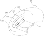
- FIG. 4 is a schematic perspective structural view of a bracket placement slot according to an embodiment of the present invention.
- FIG. 5 is a partial perspective structural view of a bracket placement slot according to an embodiment of the present invention.
- FIG. 6 is a schematic view showing a bracket placed in a bracket placement slot according to an embodiment of the present invention.
- FIG. 7 is a schematic view showing a bracket placement groove in a near-distal direction and a nip direction according to an embodiment of the present invention
- Figure 8 is a schematic view of the tooth in the near and far direction and the occlusal direction according to the embodiment of the present invention.
- Figure 9 is a perspective view showing the structure of the bracket package when the second embodiment of the present invention is closed.
- Figure 10 is a perspective view showing the three-dimensional structure of the bracket package after the embodiment of the present invention is turned over;
- Figure 11 is a perspective view showing the structure of a support member according to a second embodiment of the present invention.
- Figure 12 is a perspective view showing the three-way structure of the third tray packaging box in the embodiment of the present invention.
- Figure 13 is a side view showing the structure of a fourth inner bracket according to an embodiment of the present invention.
- Figure 14 is a partial enlarged view of Figure 13;
- the bracket package includes a box body 10 , an inner tray 12 and a cover body 20 .
- the box body 10 is provided with a placement cavity, and the inner tray 12 is disposed in the placement cavity of the box body 10;
- the tray 12 is provided with a plurality of bracket placement slots 13 for placing the brackets 30;
- the cover 20 is matched with the box body 10, and the cover body is One end of 20 is rotatably connected to one end of the casing 10, and the cover 20 is turned over with respect to the casing 10;
- the bracket placement slot 13 has a placement opening portion 131, a placement side portion 132, and a placement bottom portion 133.
- the placement side portion 132 of the bracket placement slot 13 has a top edge and a bottom edge, and the bracket placement slot 13 places the top edge of the side portion 132 and
- the placement opening portion 131 of the bracket placement slot 13 is in contact with each other, and the bottom edge of the bracket placement slot 13 placement side portion 132 is in contact with the placement bottom portion 133 of the bracket placement slot 13;
- the placement opening portion 131 of the bracket placement slot 13 is along the placement side portion 132 of the bracket placement slot 13 to the placement bottom portion 133 of the bracket placement slot 13; the placement bottom portion 133 of the bracket placement slot 13 is inclined, and the bracket placement slot 13 is placed.
- the bottom 133 is at an angle suitable for gripping the bottom support surface of the bracket package, such as between 0 and 90 degrees.
- the placement bottom 133 of the bracket placement slot 13 forms an angle of 10 to 30 degrees with the bottom support surface of the bracket package; the placement bottom 133 of the bracket placement slot 13 and the bottom of the bracket package The angle formed by the support surface depends on the different tooth positions.
- the placement bottom 133 of the bracket placement slot 13 forms an angle with the bottom support surface of the bracket package between 12 and 25 degrees; the placement bottom 133 of the bracket placement slot 13 and the bracket package The angle formed by the bottom support surface depends on the different tooth positions.
- the plane of the placement opening 131 of the bracket placement slot 13 is parallel to the bottom support surface of the bracket package, and the placement bottom 133 of the bracket placement slot 13 is a sloped surface, and the placement opening 131 of the slot 13 is placed opposite to the bracket.
- the placement side portion 132 of the bracket placement slot 13 includes a first placement side portion 1321 and a second placement side portion 1322, the first placement side portion 1321 being opposite to the second placement side portion 1322;
- the first placement side portion 1321 is provided with a first latching protrusion 1321a at a bottom edge thereof, and the first latching protrusion 1321a protrudes from the first placement side portion 1321 toward the second placement side portion 1322, and the first card position
- the protrusion 1321a and the placement bottom 133 of the bracket placement slot 13 have a card gap;
- the second placement side portion 1322 is provided with a second latching protrusion 1322a at a bottom edge thereof, and the second latching protrusion 1322a protrudes from the second placement side portion 1322 toward the first placement side portion 1321, and the second latching position
- the protrusion 1322a and the placement bottom 133 of the bracket placement slot 13 have a card gap; the second card protrusion 1322a Opposite the first card position projection 1321a;
- the first placement side portion 1321 is provided with a first side recess 1321b between the first latching projection 1321a and the placement bottom 133 of the bracket placement slot 13, the first side recess 1321b and the first latching projection 1321a and the bracket
- the placement bottom 133 of the placement slot 13 is smoothly connected;
- the second placement side portion 1322 is provided with a second side recess portion 1322b between the second latching projection 1322a and the placement bottom portion 133 of the bracket placement slot 13, the second side recess portion 1322b and the second latching projection 1322a and the bracket
- the placement bottom 133 of the placement slot 13 is smoothly connected;
- the first side recess 1321b and the second side recess 1322b have a curved curved surface
- the first placement side portion 1321 is provided with a first relief portion 1321c above the first latching projection 1321a, the first relief portion 1321c is coupled to the first latching projection 1321a, and the first relief portion 1321c is along the first latching portion.
- the opposite direction of the convex direction of the protrusion 1321a is avoided;
- the second placement side portion 1322 is provided with a second relief portion 1322c above the second latching protrusion 1322a, the second relief portion 1322c is connected to the second latching protrusion 1322a, and the second avoiding portion 1322c is along the second latching portion. The opposite direction of the convex direction of the protrusion 1322a is avoided;
- the placement side portion 132 of the bracket placement slot 13 further includes a third placement side portion 1323 and a fourth placement side portion 1324, the third placement side portion 1323 being opposite to the fourth placement side portion 1324;
- the top edges of the third placement side portion 1323 and the fourth placement side portion 1324 are gradually inclined toward the bottom direction, and the third placement side portion 1323, the fourth placement side portion 1324, and the placement bottom portion 133 of the bracket placement groove 13 are formed.
- the angle enables the gripping tool to smoothly enter the bracket placement slot 13, such as between 120 and 150 degrees;
- the third placement side portion 1323 and the fourth placement side portion 1324 have curved curved surfaces, and the top edges of the third placement side portion 1323 and the fourth placement side portion 1324 are curved, and the third placement side portion 1323 and the fourth placement side portion
- the bottom edge of the 1324 is a straight line or an arc.
- the bottom edge of the fourth placement side portion 1324 is a straight line, and the top edge of the third placement side portion 1323 and the fourth placement side portion 1324 gradually becomes smaller toward the bottom edge. ;
- the bracket is placed in the bracket placement slot of the bracket box, and the bracket placed in the bracket placement slot is in the near and far direction and the occlusion direction of the bracket in the near and far direction and the occlusion direction and the bracket is attached to the tooth surface.
- the bracket clamping method includes the following steps,
- a bracket 30 is disposed in the bracket placement slot 13 of the bracket package, and the bottom edge of the bracket 30 is at an angle suitable for gripping the bottom support surface of the bracket package, such as between 0 and 90 degrees;
- the clamping end of the holding tool extends into the bracket placement slot 13 of the bracket package. When extending, the bottom edge of the clamping end of the clamping tool is properly gripped with the bottom support surface of the bracket package. Angle, such as between 0 and 90 degrees;
- the gripping end of the gripping tool extends from the placement opening portion 131 of the bracket placement groove 13 along the placement side portion 132 of the bracket placement slot 13 to the placement bottom portion 133 of the bracket placement slot 13 until the clamping of the gripping tool The end portion projects into the clamping position of the bracket 30;
- the clamping end of the clamping tool is located on both sides of the bracket 30, and a clamping force is applied to the clamping tool, and the clamping end of the clamping tool clamps the bracket 30, and the clamping tool clamps when clamping
- the bottom edge of the end portion is at an angle suitable for gripping the bottom support surface of the bracket package, such as between 0 and 90 degrees;
- the bracket 30 is taken out from the bracket placing slot 13, and the bottom edge of the clamping end of the clamping tool is at an angle suitable for the bottom edge of the bracket 30. , such as between 0 and 90 degrees.
- the bracket packaging box comprises a box body 10, an inner tray 12 and a cover body 20.
- the inner tray 12 is disposed in the box body 10.
- the inner tray 12 is provided with a plurality of bracket placement slots 13, and the bracket slots 13 are provided.
- the bracket placement slot 13 has a placement opening 131, a placement side portion 132, and a placement bottom portion 133.
- the placement bottom portion 133 of the bracket placement slot 13 is inclined, and the placement bottom portion 133 of the bracket placement slot 13 and the bracket package
- the angle formed by the bottom support surface of the box is an angle suitable for clamping (this angle is set according to the angle of the bracket itself and the doctor's habit, such as between 0 and 90 degrees), due to the bracket placement slot
- the placement bottom 133 of the 13 is inclined, and when the bracket 30 is placed in the bracket placement slot 13, the bracket 30 is inclined as a whole, and the bottom edge of the bracket 30 is at an angle to the bottom support surface of the bracket package. Angle (this angle is set according to the angle of the bracket itself and the doctor's habits, such as between 0 and 90 degrees);
- the clamping end of the gripping tool is inserted into the bracket box.
- the clamping end portion of the holding tool protrudes from the placement opening portion 131 of the bracket placement groove 13 along the placement side portion 132 of the bracket placement groove 13 toward the placement bottom portion 133 of the bracket placement groove 13.
- the clamping end of the clamping tool Until the clamping end of the clamping tool protrudes into the clamping position of the bracket 30; a clamping force is applied to the clamping tool, and the clamping end of the clamping tool clamps the bracket 30, and when clamped, the clamp
- the angle between the bottom edge of the tool holding end and the bottom support surface of the bracket box is an angle suitable for clamping (the angle is set according to the angle of the bracket itself and the doctor's habit, such as 0 to 90 degrees); the bracket 30 is taken out from the bracket placement slot 13, and the bottom edge of the clamping end of the clamping tool and the bottom edge of the bracket 30 are at an angle suitable for clamping. (The angle is set according to the angle of the bracket itself and the doctor's habits, such as between 0 and 90 degrees);
- the bracket packaging box allows the doctor to hold the bracket 30 at a suitable clamping angle according to requirements when the bracket 30 is gripped, and then the bracket 30 is taken out, and the bracket 30 can be removed after the bracket 30 is removed.
- the clamping angle of the groove 30 is adjusted to directly bond the bracket 30 to the tooth, or the bracket 30 can be bonded to the tooth only by slightly adjusting the clamping angle of the bracket 30, which gives
- the doctor's dental treatment brings great convenience, which makes the doctor's dental correction work simple, can effectively reduce the doctor's working time, improve the efficiency of the doctor's dental correction work, and at the same time, can avoid the bracket 30
- the clamping angle requires a large adjustment, so that the bracket 30 is dropped, and even the bracket 30 is lost, thereby affecting the doctor's dental treatment.
- the placement bottom 133 of the bracket placement slot 13 and the bottom support surface of the bracket package are at an angle of between 10 and 30 degrees, the angle range being a suitable angle range; the bracket placement slot 13
- the angle between the placement bottom 133 and the bottom support surface of the bracket package depends on the different tooth positions.
- the placement bottom 133 of the bracket placement slot 13 and the bottom support surface of the bracket package are at an angle of between 12 and 25 degrees, the angle range being a more suitable angular range; The angle at which the placement bottom 133 of the trough 13 and the bottom support surface of the bracket package are dependent on the different tooth positions.
- the bottom end surface of the casing 10 is the bottom support surface of the bracket package, and the plane where the placement opening 131 of the bracket placement slot 13 is located is parallel to the bottom support surface of the bracket package, and the bracket is placed at the bottom of the slot 13 133 is a slope which is inclined with respect to a plane in which the placement opening 131 of the bracket placement slot 13 is located, and
- the angle formed by the plane of the placement opening 131 of the bracket placement slot 13 is an angle suitable for clamping (the angle is set according to the angle of the bracket itself and the usage habit of the doctor, such as at 0 to 90 degrees.
- the bracket 30 placed in the bracket placement slot 13 is inclined with respect to the bottom support surface of the bracket package, and the bottom edge of the bracket 30 and the bottom of the bracket box
- the angle formed by the support surface is an angle suitable for gripping (this angle is set according to the angle of the bracket itself and the doctor's habit, such as between 0 and 90 degrees).
- the bracket placement slot 13 has a first placement side portion 1321 opposite to the second placement side portion 1322.
- the first placement side portion 1321 is provided with a first latching protrusion 1321a at a bottom edge thereof, and a second placement side portion 1322 is provided with a second latching protrusion 1322a at a bottom edge thereof.
- the first latching protrusion 1321a is opposite to the second latching protrusion 1322a, and the first latching protrusion 1321a and the second latching protrusion 1322a are disposed.
- the first placement side portion 1321 is provided with a first side recess 1321b between the first latching projection 1321a and the placement bottom 133 of the bracket placement slot 13, and the second placement side portion 1322 is at the second latching projection 1322a.
- a second side recess 1322b is disposed between the placement bottom 133 of the bracket placement slot 13, and the first side recess 1321b and the second side recess 1322b have a curved curved surface, and the first side recess 1321b and the second side recess 1322b are disposed.
- the first placement side portion 1321 is provided with a first relief portion 1321c above the first latching protrusion 1321a
- the second placement side portion 1322 is provided with a second relief portion 1322c above the second latching projection 1322a.
- the arrangement of the first relief portion 1321c and the second relief portion 1322c can be used to avoid the bracket 30 when it is placed in or taken out of the bracket placement slot 13, and is convenient for loading or unloading the bracket 30.
- the bracket placement slot 13 is opposite to the fourth placement side portion 1324, and the top edges of the third placement side portion 1323 and the fourth placement side portion 1324 are gradually inclined toward the bottom direction, and the third The angle between the placement side portion 1323, the fourth placement side portion 1324 and the placement bottom portion 133 of the bracket placement groove 13 enables the gripping tool to smoothly enter the bracket placement groove (this angle is based on the angle of the bracket itself and the doctor Use the habit to set, such as between 120 and 150 degrees), the third placement side 1323, the fourth release
- the arrangement of the side portions 1324 can facilitate the access of the brackets 30, especially for the doctor to grasp the brackets 30, which can greatly improve the rate at which the doctor can grip the brackets 30.
- the top edges of the third placement side portion 1323 and the fourth placement side portion 1324 are curved, and the bottom edges of the third placement side portion 1323 and the fourth placement side portion 1324 are straight lines, and the third placement side portions 1323 and 4
- the top edge of the placement side portion 1324 gradually becomes smaller toward the bottom edge, and the placement opening portion 131 of the bracket placement groove 13 becomes smaller toward the placement bottom portion 133, and the engagement of the bracket 30 can be facilitated while facilitating the access of the bracket 30.
- the auxiliary function reflects the rationality of the space design of the bracket placement slot 13.
- the bracket placed in the bracket placement slot is in the near-distal direction and the occlusal direction in the near-distal direction and the occlusion direction of the bracket, and the doctor does not need to adjust the bracket after the bracket is removed.
- the position allows the doctor to accurately and quickly grasp the bracket to adhere to the corresponding tooth.
- At least one of the two sides of the cover body 20 is provided with a fixing protrusion 23, a limiting protrusion 24 and a supporting member 25.
- the fixing protrusion 23 is spaced apart from the limiting protrusion 24, and the end of the fixing protrusion 23 is provided with a card protrusion 231.
- the support member 25 is provided with a rotating hole 251 and a limiting card slot 252.
- the supporting member 25 is rotatably connected to the fixing protrusion 23 through the rotating hole 251, and the limiting card slot 252 is matched with the limiting protrusion 24;
- a positioning protrusion 11 is disposed on at least one of the two sides of the box body 10, and the positioning protrusion 11 corresponds to the limiting protrusion 24, and cooperates with the limiting card slot 252;
- the cover body 20 can be turned 360 degrees with respect to the casing 10, and the bottom of the cover body 20 is formed as the bottom support surface of the bracket package, and the bottom support surface can be adsorbed or adhered to the work surface, and the cover body 20 is suitable for clamping the angle of the box body 10, such as between 0 and 90 degrees, the bottom portion 133 of the bracket placement slot 13 and the bottom support surface of the bracket box are at an appropriate angle, such as at 0 ⁇ Between 90 degrees;
- a positioning slot 253 is further disposed on the supporting member 25, and the positioning slot 253 is matched with the positioning protrusion 11.
- the positioning slot 253 is disposed between the rotating hole 251 of the supporting member 25 and the limiting slot 252, and the positioning slot 253 is disposed.
- the orientation is the same as or opposite to the orientation of the limit card slot 252.
- a fixing protrusion 23, a limiting protrusion 24 and a supporting member 25 are disposed on the side of the cover body 20.
- the fixing protrusion 23 is spaced apart from the limiting protrusion 24, and the supporting member 25 is provided with a rotating hole 251 and a limiting card slot 252.
- the support member 25 is rotatably connected to the fixing protrusion 23, and the limiting card slot 252 is matched with the limiting protrusion 24, and the positioning portion 11 is correspondingly disposed on the side portion of the box body 10.
- the positioning protrusion 11 cooperates with the limiting protrusion 24, After the cover 20 of the bracket is turned over, the positioning protrusion 11 on the side of the box 10 is locked to the limiting slot 252 of the support member 25.
- the box 10 is fixed and is at an angle with the cover 20, and the bracket When the cover 20 of the packaging box is turned over and placed on the work surface, the cover 20 is located below the casing 10.
- the bottom support surface of the cover 20 is in contact with the work surface, and the casing 10 is inclined with respect to the cover 20 and the work surface.
- the angle formed by the body 10 and the bottom support surface of the cover is an angle suitable for clamping (the angle is set according to the angle of the bracket itself and the doctor's habit, such as between 0 and 90 degrees).
- the angle at which the bottom portion 133 of the groove placement groove 13 and the bottom support surface of the cover body are at an angle suitable for clamping (the angle is based on the bracket And angle setting of the doctor habits, such as between 0 to 90 degrees);
- the limiting slot 252 of the support member 25 can cooperate with the limiting protrusion 24 on the side of the cover 20, thereby fixing the support member 25;
- the positioning of the positioning slot 253 on the support member 25 can be used to change the relative position of the box body 10 and the cover body 20, and adjust the angle between the box body 10 and the cover body 20;
- the bottom support surface can be adsorbed or adhered to the work surface, and the inverted bracket box is placed on the work surface, and the bottom support surface can have a good anti-slip effect, and the anti-slip connection with the work surface is relatively large.
- the friction coefficient is so great that the friction between the working surface and the work surface is large. Under the action of the general force, the package is basically not displaced, thereby preventing the anti-slip effect.
- a step 14 is disposed at a lower surface of the other end of the casing 10.
- the bottom support surface of the step 14 is the bottom support surface of the bracket package, and the other end of the casing 10 faces the casing 10.
- One end of the bracket is inclined, and the bottom 133 of the bracket placement slot 13 is inclined.
- the placement bottom 133 of the bracket placement slot 13 is at an angle suitable for gripping the bottom support surface of the bracket package, such as between 0 and 90 degrees.
- a step 14 is disposed at a lower surface of the other end of the casing 10.
- the bottom support surface of the step 14 is the bottom support surface of the bracket package, and the other end of the casing 10 is directed to the casing.
- One end of 10 is inclined, and the bottom portion 133 of the bracket placing groove 13 is inclined, and the angle between the bottom portion 133 of the bracket placing groove 13 and the bottom supporting surface of the bracket box is an angle suitable for clamping (this angle is based on
- the brackets are set by themselves and the doctor's habits, such as between 0 and 90 degrees.
- the inner tray 12 is provided with at least one inclined portion 121.
- the surface of the inclined portion 121 is at an angle suitable for gripping the bottom supporting surface of the bracket package, such as between 0 and 90 degrees; and the plurality of brackets are disposed in the slot 13
- the bottom portion 133 of the bracket placement slot 13 is inclined at an inclined portion 121 of the bracket 12, and the placement bottom portion 133 of the bracket placement slot 13 is at an angle suitable for gripping the bottom support surface of the bracket package, as in It is between 0 and 90 degrees and is parallel to the surface of the inclined portion 121 on the inner tray 12.
- the inner support 12 is provided with an inclined portion 121.
- the bottom end surface of the casing 10 is the bottom support surface of the bracket package, and the angle between the surface of the inclined portion 121 and the bottom support surface of the bracket package is suitable for clamping.
- Angle (the angle is set according to the angle of the bracket itself and the doctor's usage habit, such as between 0 and 90 degrees), and a plurality of bracket placement slots 13 are provided at the inclined portion 121 on the inner tray 12,
- the placement bottom 133 of the slot placement slot 13 is inclined, and the angle between the placement bottom 133 of the bracket placement slot 13 and the bottom support surface of the bracket package is an angle suitable for clamping (this angle is based on the angle of the bracket itself)
- the setting of the doctor's use habits such as between 0 and 90 degrees, and parallel to the surface of the inclined portion 121 of the inner tray 12, when the bracket package is placed on the work surface, the bottom of the bracket placement slot 13 is placed
- the angle formed by the 133 and the bottom support surface of the bracket package is
Landscapes
- Health & Medical Sciences (AREA)
- Life Sciences & Earth Sciences (AREA)
- General Health & Medical Sciences (AREA)
- Oral & Maxillofacial Surgery (AREA)
- Dentistry (AREA)
- Epidemiology (AREA)
- Veterinary Medicine (AREA)
- Animal Behavior & Ethology (AREA)
- Public Health (AREA)
- Mechanical Engineering (AREA)
- Engineering & Computer Science (AREA)
- Packaging Of Annular Or Rod-Shaped Articles, Wearing Apparel, Cassettes, Or The Like (AREA)
- Auxiliary Apparatuses For Manual Packaging Operations (AREA)
- Dental Tools And Instruments Or Auxiliary Dental Instruments (AREA)
- Details Of Rigid Or Semi-Rigid Containers (AREA)
Abstract
一种托槽包装盒及托槽夹取方法,托槽包装盒包括盒体(10)、内托(12)及盖体(20),盒体(10)上设有放置腔,内托(12)设于盒体(10)的放置腔中;内托(12)上设有多个托槽放置槽(13),托槽放置槽(13)用于放置托槽(30);盖体(20)与盒体(10)相匹配;托槽放置槽(13)具有放置口部(131)、放置侧部(132)及放置底部(133),放置侧部(132)设有卡位凸起(1321a,1322a),托槽放置槽(13)的放置底部(133)倾斜;托槽夹取方法包括以下步骤,将夹持工具的夹持端部伸入至托槽放置槽(13),将托槽(30)从托槽放置槽(13)中取出,夹持工具夹持端部的底沿与托槽底沿成一适宜夹取的角度。上述托槽包装盒及托槽夹取方法能在医生进行牙齿矫治工作时带来便利,使工作简单化。
Description
本发明涉及牙齿正畸托槽技术领域,具体涉及一种托槽包装盒及托槽夹取方法。
托槽是固定矫治技术的重要部件,弓丝通过托槽而对牙施以各种类型的矫治力,托槽的主要作用在于固定弓丝,从而使弓丝更好的发挥作用,传递矫治力,以此控制牙齿三维的移动,达到正畸矫治的目的。
托槽包装盒是用来包装托槽的盒子,其能够保证运输中产品的安全,提升产品的档次等。
现有的托槽包装盒主要包括盒体、盖体及内托,内托设于盒体中,内托上设有托槽放置槽,托槽放置槽用于放置托槽,医生在进行牙齿矫治工作时,需要用夹持工具将托槽从托槽放置槽中取出,由于牙齿及托槽都存在倾斜,托槽取出后需要对托槽的夹持角度进行较大的调整,再将托槽粘结于牙齿上。然而,托槽夹持角度的调整给医生的牙齿矫治工作带来了极大的不便,托槽夹持角度的调整使医生的牙齿矫治工作变得复杂,增加了医生的工作时长,并且,由于托槽的夹持角度需要进行较大的调整,医生在操作时,可能会导致托槽掉落,甚至丢失托槽,在运输时或者搬运时由于没有限位,容易脱落,导致不同牙位之间混淆。
发明内容
本发明的目的在于提供一种托槽包装盒及托槽夹取方法,该托槽包装盒及
托槽夹取方法能在医生进行牙齿矫治工作时,给医生的牙齿矫治工作带来便利,使医生的牙齿矫治工作变得简单化。
其技术方案如下:
托槽包装盒,包括盒体、内托及盖体,
所述盒体上设有放置腔,所述内托设于盒体的放置腔中;所述内托上设有多个托槽放置槽,所述托槽放置槽用于放置托槽;所述盖体与盒体相匹配;
所述托槽放置槽具有放置口部、放置侧部及放置底部,所述托槽放置槽的放置侧部具有顶沿及底沿,托槽放置槽放置侧部的顶沿与托槽放置槽的放置口部相接,托槽放置槽放置侧部的底沿与托槽放置槽的放置底部相接。
进一步地,所述托槽放置槽的放置侧部包括第一放置侧部及第二放置侧部,所述第一放置侧部与第二放置侧部相对;
所述第一放置侧部在其底沿处设有第一卡位凸起,第一卡位凸起相对第一放置侧部向第二放置侧部凸出,且第一卡位凸起与托槽放置槽的放置底部留有卡位间隙;
所述第二放置侧部在其底沿处设有第二卡位凸起,第二卡位凸起相对第二放置侧部向第一放置侧部凸出,且第二卡位凸起与托槽放置槽的放置底部留有卡位间隙;所述第二卡位凸起与第一卡位凸起相对。
进一步地,所述第一放置侧部在第一卡位凸起与托槽放置槽的放置底部之间设有第一侧凹部,第一侧凹部与第一卡位凸起及托槽放置槽的放置底部圆滑连接;
所述第二放置侧部在第二卡位凸起与托槽放置槽的放置底部之间设有第二侧凹部,第二侧凹部与第二卡位凸起及托槽放置槽的放置底部圆滑连接;
所述第一侧凹部及第二侧凹部呈弧形曲面。
进一步地,所述第一放置侧部在第一卡位凸起的上方设有第一避让部,第
一避让部与第一卡位凸起连接,且第一避让部沿第一卡位凸起凸出方向的相反方向避让;
所述第二放置侧部在第二卡位凸起的上方设有第二避让部,第二避让部与第二卡位凸起连接,且第二避让部沿第二卡位凸起凸出方向的相反方向避让。
进一步地,所述托槽放置槽的放置侧部还包括第三放置侧部及第四放置侧部,所述第三放置侧部与第四放置侧部相对;
所述第三放置侧部、第四放置侧部的顶沿向底沿方向逐渐倾斜,且第三放置侧部、第四放置侧部与所述托槽放置槽的放置底部所成的角度能使夹持工具顺畅地进入所述托槽放置槽。
进一步地,所述第三放置侧部、第四放置侧部呈弧形曲面,第三放置侧部、第四放置侧部的顶沿为弧形,第三放置侧部、第四放置侧部的底沿为直线或弧形,第三放置侧部、第四放置侧部的顶沿向底沿逐渐变小。
进一步地,所述托槽放置槽的放置口部所在的平面与所述托槽包装盒的底部支撑面平行,托槽放置槽的放置底部为斜面,其相对所述托槽包装盒的底部支撑面倾斜。
进一步地,所述盖体的一端与盒体的一端转动连接,所述盖体相对于盒体翻转,所述盖体翻转后盖体的底部形成为托槽包装盒的底部支撑面,且盖体与所述盒体成一适宜夹取的角度,所述托槽放置槽的放置底部与托槽包装盒的底部支撑面成一适宜夹取的角度。
进一步地,所述盖体两侧的至少其中一侧上设有固定凸、限位凸及支撑件,所述固定凸与限位凸留有距离,固定凸的端部设有卡凸,所述支撑件上设有转孔及限位卡槽,支撑件通过转孔与固定凸的转动连接,所述限位卡槽与限位凸相配合;
所述盒体两侧的至少其中一侧上设有定位凸,所述定位凸与限位凸相对应,并与所述限位卡槽相配合。
进一步地,所述支撑件上还设有定位卡槽,所述定位卡槽与定位凸相配合,定位卡槽设于支撑件的转孔与限位卡槽之间,定位卡槽的朝向与限位卡槽的朝向相同或相反。
进一步地,所述底部支撑面能吸附或粘附于工作台面上。
进一步地,所述盒体另一端的下表面处设有一台阶;所述托槽包装盒置于工作台面时,所述台阶的底部支撑面为托槽包装盒的底部支撑面,所述盒体的另一端向盒体的一端倾斜,所述托槽放置槽的放置底部倾斜,托槽放置槽的放置底部与托槽包装盒的底部支撑面成一适宜夹取的角度。
进一步地,所述内托上设有至少一处倾斜部,所述倾斜部的表面与托槽包装盒的底部支撑面成一适宜夹取的角度;多个所述托槽放置槽设于内托上的倾斜部处,托槽放置槽的放置底部倾斜,托槽放置槽的放置底部与托槽包装盒的底部支撑面成一适宜夹取的角度,且与所述内托上倾斜部的表面平行。
进一步地,所述托槽包装盒的托槽放置槽中放置有托槽,放置于托槽放置槽中的托槽其在近远中方向及咬合方向与托槽粘贴于牙齿表面上的近远中方向及咬合方向一致。
托槽夹取方法,包括以下步骤,
托槽包装盒的托槽放置槽中放置有托槽,托槽的底沿与托槽包装盒的底部支撑面成一适宜夹取的角度;将夹持工具的夹持端部伸入至所述托槽包装盒的托槽放置槽中,伸入时,夹持工具夹持端部的底沿与托槽包装盒的底部支撑面成一适宜夹取的角度;
夹持工具的夹持端部从托槽放置槽的放置口部沿托槽放置槽的放置侧部向托槽放置槽的放置底部伸入,直至夹持工具的夹持端部伸入至托槽的夹持位置;
夹持工具的夹持端部位于托槽的两侧,向夹持工具施加夹持力,夹持工具的夹持端部对托槽进行夹持,夹持时,夹持工具夹持端部的底沿与托槽包装盒的底部支撑面成一适宜夹取的角度;
夹持工具的夹持端部夹持托槽后,将托槽从托槽放置槽中取出,夹持工具夹持端部的底沿与托槽底沿成一适宜夹取的角度。
需要说明的是:
前述“第一、第二…”不代表具体的数量及顺序,仅仅是用于对名称的区分;
前述“近远中方向”包括近中方向及远中方向,“近中方向”可表示牙齿上离面部中线较近的方向,“远中方向”可表示牙齿上离面部中线较远的方向;
前述“咬合方向”可表示牙齿的咬合方向。
下面对本发明的优点或原理进行说明:
1、托槽包装盒,包括盒体、内托及盖体,内托设于盒体中,内托上设有多个托槽放置槽,托槽放置槽用于放置托槽,托槽放置槽具有放置口部、放置侧部及放置底部,托槽放置槽的放置底部倾斜,托槽放置槽的放置底部与托槽包装盒的底部支撑面所成的角度为一适宜夹取的角度,由于托槽放置槽的放置底部倾斜,托槽放置于托槽放置槽时,托槽整体会倾斜,托槽的底沿与托槽包装盒的底部支撑面所成的角度为一适宜夹取的角度;
医生在进行牙齿矫治工作时,将夹持工具的夹持端部伸入至托槽包装盒的托槽放置槽中,夹持工具的夹持端部从托槽放置槽的放置口部沿托槽放置槽的放置侧部向托槽放置槽的放置底部伸入,直至夹持工具的夹持端部伸入至托槽的夹持位置;向夹持工具施加夹持力,夹持工具的夹持端部对托槽进行夹持,夹持时,夹持工具夹持端部的底沿与托槽包装盒的底部支撑面所成的角度为一适宜夹取的角度;将托槽从托槽放置槽中取出,夹持工具夹持端部的底沿与托槽底沿所成的夹持角度为一适宜夹取的角度;
该托槽包装盒,医生在夹取托槽时,可用夹持工具根据需求按适宜的夹持角度夹持托槽,进而将托槽取出,托槽取出后医生可无需对托槽的夹持角度做调整,直接将托槽粘结于牙齿上,或仅需对托槽的夹持角度做轻微的调整,便可将托槽粘结于牙齿上,其给医生的牙齿矫治工作带来了极大的方便,使医生
的牙齿矫治工作变得简单化,能有效减少医生的工作时长,提高医生牙齿矫治工作的效率;同时,能够尽量避免因托槽的夹持角度需要进行较大的调整,使得托槽掉落,甚至丢失托槽,进而影响医生的牙齿矫治工作。
2、托槽放置槽中,第一放置侧部与第二放置侧部相对,第一放置侧部在其底沿处设有第一卡位凸起,第二放置侧部在其底沿处设有第二卡位凸起,第一卡位凸起与第二卡位凸起相对,第一卡位凸起及第二卡位凸起的设置能在托槽放置于托槽放置槽时,对托槽起到卡合的作用,避免托槽在托槽放置槽中移动,甚至掉出到托槽放置槽外,能够有效保证托槽运输中的安全,提高对托槽的保护。
3、第一放置侧部在第一卡位凸起与托槽放置槽的放置底部之间设有第一侧凹部,第二放置侧部在第二卡位凸起与托槽放置槽的放置底部之间设有第二侧凹部,第一侧凹部及第二侧凹部呈弧形曲面,第一侧凹部及第二侧凹部的设置能便于托槽放入托槽放置槽时,托槽卡于托槽放置槽中,同时,能便于托槽的取出。
4、第一放置侧部在第一卡位凸起的上方设有第一避让部,第二放置侧部在第二卡位凸起的上方设有第二避让部,第一避让部及第二避让部的设置能为托槽放入或取出于托槽放置槽时起到避让的作用,为托槽的放入或取出带来的方便。
5、托槽放置槽中,第三放置侧部与第四放置侧部相对,第三放置侧部、第四放置侧部的顶沿向底沿方向逐渐倾斜,且第三放置侧部、第四放置侧部与托槽放置槽的放置底部所成的角度能使夹持工具顺畅地进入托槽放置槽,第三放置侧部、第四放置侧部的设置方式能便于托槽的存取,尤其给医生夹取托槽时带来了极大的方便,能有效提高医生夹取托槽的速率。
6、第三放置侧部、第四放置侧部的顶沿为弧形,第三放置侧部、第四放置侧部的底沿为直线,第三放置侧部、第四放置侧部的顶沿向底沿逐渐变小,托槽放置槽的放置口部向放置底部变小,在便于托槽存取的同时,能对托槽的卡合起到辅助性的作用,体现了托槽放置槽的空间设计的合理性。
7、盒体的底端面为托槽包装盒的底部支撑面,托槽放置槽的放置口部所在的平面与托槽包装盒的底部支撑面平行,托槽放置槽的放置底部为斜面,其相对托槽放置槽的放置口部所在的平面倾斜,且与托槽放置槽的放置口部所在平面所成的角度为一适宜夹取的角度,该托槽包装盒置于工作台面时,放置于托槽放置槽中的托槽相对托槽包装盒的底部支撑面倾斜,托槽的底沿与托槽包装盒的底部支撑面所成的角度为一适宜夹取的角度。
8、盖体与盒体翻转连接,盖体能相对于盒体翻转一定的角度,盖体翻转后与盒体所成的角度为一适宜夹取的角度,盖体的底部支撑面为托槽包装盒的底部支撑面,托槽放置槽的放置底部与托槽包装盒的底部支撑面所成的角度为一适宜夹取的角度,该托槽包装盒的盖体翻转后,将翻转后的托槽包装盒置于工作台面时,盖体位于盒体的下方,盖体的底部支撑面与工作台面接触,盒体相对于盖体及工作台面倾斜,盒体与盖体的底部支撑面所成的角度为一适宜夹取的角度,托槽放置槽的放置底部与托槽包装盒的底部支撑面所成的角度为一适宜夹取的角度。
9、盖体的侧部上设有固定凸、限位凸及支撑件,固定凸与限位凸留有距离,支撑件上设有转孔及限位卡槽,支撑件与固定凸的转动连接,限位卡槽与限位凸相配合,盒体的侧部上对应设有定位凸,定位凸与与限位凸相配合,该托槽包装盒的盖体翻转后,盒体侧部上的定位凸卡于支撑件的限位卡槽,盒体固定,并与盖体成一夹角,托槽包装盒的盖体翻转后置于工作台面时,盖体位于盒体的下方,盖体的底部支撑面与工作台面接触,盒体相对于盖体及工作台面倾斜,盒体与盖体的底部支撑面所成的角度为一适宜夹取的角度,托槽放置槽的放置底部与盖体的底部支撑面所成的角度为一适宜夹取的角度;
当托槽包装盒合上时,支撑件的限位卡槽可与盖体侧部上的限位凸配合,从而固定支撑件。
10、支撑件上定位卡槽的设置,能用于改变盒体与盖体的相对位置,调节盒体与盖体所成夹角的角度。
11、底部支撑面能吸附或粘附于工作台面上,经过翻转后的托槽包装盒置
于工作台面上,底部支撑面能起到很好地防滑效果,其与工作台面防滑连接,其具有较大的摩擦系数,所以在使用时与工作台面的摩擦力较大,在一般力度的作用下,包装盒基本不会发生移位,从而起到防滑作用。
12、盒体另一端的下表面处设有一台阶,该托槽包装盒置于工作台面时,台阶的底部支撑面为托槽包装盒的底部支撑面,盒体的另一端向盒体的一端倾斜,托槽放置槽的放置底部倾斜,托槽放置槽的放置底部与托槽包装盒的底部支撑面所成的角度为一适宜夹取的角度。
13、内托上设有倾斜部,盒体的底端面为托槽包装盒的底部支撑面,倾斜部的表面与托槽包装盒的底部支撑面所成的角度为一适宜夹取的角度,多个托槽放置槽设于内托上的倾斜部处,托槽放置槽的放置底部倾斜,托槽放置槽的放置底部与托槽包装盒的底部支撑面所成的角度为一适宜夹取的角度,且与内托上倾斜部的表面平行,该托槽包装盒置于工作台面时,托槽放置槽的放置底部与托槽包装盒的底部支撑面所成的角度为一适宜夹取的角度。
14、放置于托槽放置槽中的托槽其在近远中方向及咬合方向与托槽粘贴于牙齿表面上的近远中方向及咬合方向一致,医生夹取出托槽后无需再调整托槽的位置,能便于医生准确、快速地夹取出托槽粘附于对应的牙齿上。
图1是本发明实施例一托槽包装盒闭合时的立体结构示意图;
图2是本发明实施例一托槽包装盒的结构分解示意图;
图3是本发明实施例一托槽包装盒打开时的立体结构示意图;
图4是本发明实施例一托槽放置槽的立体结构示意图;
图5是本发明实施例一托槽放置槽的局部立体结构示意图;
图6是本发明实施例一托槽放置于托槽放置槽的示意图;
图7是本发明实施例一托槽放置槽在近远中方向及咬合方向的示意图;
图8是本发明实施例一牙齿在近远中方向及咬合方向的示意图;
图9是本发明实施例二托槽包装盒闭合时的立体结构示意图;
图10是本发明实施例二托槽包装盒翻转后的立体结构示意图;
图11是本发明实施例二支撑件的立体结构示意图;
图12是本发明实施例三托槽包装盒闭合时的立体结构示意图;
图13是本发明实施例四内托的侧视结构示意图;
图14是图13的局部放大图;
附图标记说明:
10、盒体,11、定位凸,12、内托,121、倾斜部,13、托槽放置槽,131、放置口部,132、放置侧部,1321、第一放置侧部,1321a、第一卡位凸起,1321b、第一侧凹部,1321c、第一避让部,1322、第二放置侧部,1322a、第二卡位凸起,1322b、第二侧凹部,1322c、第二避让部,1323、第三放置侧部,1324、第四放置侧部,133、放置底部,14、台阶,20、盖体,23、固定凸,231、卡凸,24、限位凸,25、支撑件,251、转孔,252、限位卡槽,253、定位卡槽,30、托槽。
下面对本发明的实施例进行详细说明。
实施例一
如图1至图8所示,托槽包装盒,包括盒体10、内托12及盖体20,盒体10上设有放置腔,内托12设于盒体10的放置腔中;内托12上设有多个托槽放置槽13,托槽放置槽13用于放置托槽30;盖体20与盒体10相匹配,盖体
20的一端与盒体10的一端转动连接,盖体20相对于盒体10翻转;
托槽放置槽13具有放置口部131、放置侧部132及放置底部133,托槽放置槽13的放置侧部132具有顶沿及底沿,托槽放置槽13放置侧部132的顶沿与托槽放置槽13的放置口部131相接,托槽放置槽13放置侧部132的底沿与托槽放置槽13的放置底部133相接;
托槽放置槽13的放置口部131沿托槽放置槽13的放置侧部132到托槽放置槽13的放置底部133;托槽放置槽13的放置底部133倾斜,托槽放置槽13的放置底部133与托槽包装盒的底部支撑面成一适宜夹取的角度,如在0~90度之间。
作为优选的,托槽放置槽13的放置底部133与托槽包装盒的底部支撑面所成的角度在10~30度之间;托槽放置槽13的放置底部133与托槽包装盒的底部支撑面所成的角度根据不同的牙位而定。
作为更优选的,托槽放置槽13的放置底部133与托槽包装盒的底部支撑面所成的角度在12~25度之间;托槽放置槽13的放置底部133与托槽包装盒的底部支撑面所成的角度根据不同的牙位而定。
其中,托槽放置槽13的放置口部131所在的平面与托槽包装盒的底部支撑面平行,托槽放置槽13的放置底部133为斜面,其相对托槽放置槽13的放置口部131所在的平面倾斜;
托槽放置槽13的放置侧部132包括第一放置侧部1321及第二放置侧部1322,第一放置侧部1321与第二放置侧部1322相对;
第一放置侧部1321在其底沿处设有第一卡位凸起1321a,第一卡位凸起1321a相对第一放置侧部1321向第二放置侧部1322凸出,且第一卡位凸起1321a与托槽放置槽13的放置底部133留有卡位间隙;
第二放置侧部1322在其底沿处设有第二卡位凸起1322a,第二卡位凸起1322a相对第二放置侧部1322向第一放置侧部1321凸出,且第二卡位凸起1322a与托槽放置槽13的放置底部133留有卡位间隙;第二卡位凸起1322a
与第一卡位凸起1321a相对;
第一放置侧部1321在第一卡位凸起1321a与托槽放置槽13的放置底部133之间设有第一侧凹部1321b,第一侧凹部1321b与第一卡位凸起1321a及托槽放置槽13的放置底部133圆滑连接;
第二放置侧部1322在第二卡位凸起1322a与托槽放置槽13的放置底部133之间设有第二侧凹部1322b,第二侧凹部1322b与第二卡位凸起1322a及托槽放置槽13的放置底部133圆滑连接;
第一侧凹部1321b及第二侧凹部1322b呈弧形曲面;
第一放置侧部1321在第一卡位凸起1321a的上方设有第一避让部1321c,第一避让部1321c与第一卡位凸起1321a连接,且第一避让部1321c沿第一卡位凸起1321a凸出方向的相反方向避让;
第二放置侧部1322在第二卡位凸起1322a的上方设有第二避让部1322c,第二避让部1322c与第二卡位凸起1322a连接,且第二避让部1322c沿第二卡位凸起1322a凸出方向的相反方向避让;
托槽放置槽13的放置侧部132还包括第三放置侧部1323及第四放置侧部1324,第三放置侧部1323与第四放置侧部1324相对;
第三放置侧部1323、第四放置侧部1324的顶沿向底沿方向逐渐倾斜,且第三放置侧部1323、第四放置侧部1324与托槽放置槽13的放置底部133所成的角度能使夹持工具顺畅地进入托槽放置槽13,如在120~150度之间;
第三放置侧部1323、第四放置侧部1324呈弧形曲面,第三放置侧部1323、第四放置侧部1324的顶沿为弧形,第三放置侧部1323、第四放置侧部1324的底沿为直线或弧形,在本实施例中,第四放置侧部1324的底沿为直线,第三放置侧部1323、第四放置侧部1324的顶沿向底沿逐渐变小;
托槽包装盒的托槽放置槽中放置有托槽,放置于托槽放置槽中的托槽其在近远中方向及咬合方向与托槽粘贴于牙齿表面上的近远中方向及咬合方向一
致。
托槽夹取方法,包括以下步骤,
托槽包装盒的托槽放置槽13中放置有托槽30,托槽30的底沿与托槽包装盒的底部支撑面成一适宜夹取的角度,如在0~90度之间;将夹持工具的夹持端部伸入至托槽包装盒的托槽放置槽13中,伸入时,夹持工具夹持端部的底沿与托槽包装盒的底部支撑面成一适宜夹取的角度,如在0~90度之间;
夹持工具的夹持端部从托槽放置槽13的放置口部131沿托槽放置槽13的放置侧部132向托槽放置槽13的放置底部133伸入,直至夹持工具的夹持端部伸入至托槽30的夹持位置;
夹持工具的夹持端部位于托槽30的两侧,向夹持工具施加夹持力,夹持工具的夹持端部对托槽30进行夹持,夹持时,夹持工具夹持端部的底沿与托槽包装盒的底部支撑面成一适宜夹取的角度,如在0~90度之间;
夹持工具的夹持端部夹持托槽30后,将托槽30从托槽放置槽13中取出,夹持工具夹持端部的底沿与托槽30底沿成一适宜夹取的角度,如在0~90度之间。
本实施例的优点:
1、托槽包装盒,包括盒体10、内托12及盖体20,内托12设于盒体10中,内托12上设有多个托槽放置槽13,托槽放置槽13用于放置托槽30,托槽放置槽13具有放置口部131、放置侧部132及放置底部133,托槽放置槽13的放置底部133倾斜,托槽放置槽13的放置底部133与托槽包装盒的底部支撑面所成的角度为一适宜夹取的角度(该角度是根据托槽镊自身的角度以及医生使用习惯进行设置的,如在0~90度之间),由于托槽放置槽13的放置底部133倾斜,托槽30放置于托槽放置槽13时,托槽30整体会倾斜,托槽30的底沿与托槽包装盒的底部支撑面所成的角度为一适宜夹取的角度(该角度是根据托槽镊自身的角度以及医生使用习惯进行设置的,如在0~90度之间);
医生在进行牙齿矫治工作时,将夹持工具的夹持端部伸入至托槽包装盒的
托槽放置槽13中,夹持工具的夹持端部从托槽放置槽13的放置口部131沿托槽放置槽13的放置侧部132向托槽放置槽13的放置底部133伸入,直至夹持工具的夹持端部伸入至托槽30的夹持位置;向夹持工具施加夹持力,夹持工具的夹持端部对托槽30进行夹持,夹持时,夹持工具夹持端部的底沿与托槽包装盒的底部支撑面所成的角度为一适宜夹取的角度(该角度是根据托槽镊自身的角度以及医生使用习惯进行设置的,如在0~90度之间);将托槽30从托槽放置槽13中取出,夹持工具夹持端部的底沿与托槽30底沿所成的夹持角度为一适宜夹取的角度(该角度是根据托槽镊自身的角度以及医生使用习惯进行设置的,如在0~90度之间);
该托槽包装盒,医生在夹取托槽30时,可用夹持工具根据需求按适宜的夹持角度夹持托槽30,进而将托槽30取出,托槽30取出后医生可无需对托槽30的夹持角度做调整,直接将托槽30粘结于牙齿上,或仅需对托槽30的夹持角度做轻微的调整,便可将托槽30粘结于牙齿上,其给医生的牙齿矫治工作带来了极大的方便,使医生的牙齿矫治工作变得简单化,能有效减少医生的工作时长,提高医生牙齿矫治工作的效率;同时,能够尽量避免因托槽30的夹持角度需要进行较大的调整,使得托槽30掉落,甚至丢失托槽30,进而影响医生的牙齿矫治工作。
2、优选的,托槽放置槽13的放置底部133与托槽包装盒的底部支撑面所成的角度在10~30度之间,该角度范围为较为适宜的角度范围;托槽放置槽13的放置底部133与托槽包装盒的底部支撑面所成的角度根据不同的牙位而定。
3、更优选的,托槽放置槽13的放置底部133与托槽包装盒的底部支撑面所成的角度在12~25度之间,该角度范围为更为适宜的角度范围;托槽放置槽13的放置底部133与托槽包装盒的底部支撑面所成的角度根据不同的牙位而定。
4、盒体10的底端面为托槽包装盒的底部支撑面,托槽放置槽13的放置口部131所在的平面与托槽包装盒的底部支撑面平行,托槽放置槽13的放置底部133为斜面,其相对托槽放置槽13的放置口部131所在的平面倾斜,且
与托槽放置槽13的放置口部131所在平面所成的角度为一适宜夹取的角度(该角度是根据托槽镊自身的角度以及医生使用习惯进行设置的,如在0~90度之间),该托槽包装盒置于工作台面时,放置于托槽放置槽13中的托槽30相对托槽包装盒的底部支撑面倾斜,托槽30的底沿与托槽包装盒的底部支撑面所成的角度为一适宜夹取的角度(该角度是根据托槽镊自身的角度以及医生使用习惯进行设置的,如在0~90度之间)。
5、托槽放置槽13中,第一放置侧部1321与第二放置侧部1322相对,第一放置侧部1321在其底沿处设有第一卡位凸起1321a,第二放置侧部1322在其底沿处设有第二卡位凸起1322a,第一卡位凸起1321a与第二卡位凸起1322a相对,第一卡位凸起1321a及第二卡位凸起1322a的设置能在托槽30放置于托槽放置槽13时,对托槽30起到卡合的作用,避免托槽30在托槽放置槽13中移动,甚至掉出到托槽放置槽13外,能够有效保证托槽30运输中的安全,提高对托槽30的保护。
6、第一放置侧部1321在第一卡位凸起1321a与托槽放置槽13的放置底部133之间设有第一侧凹部1321b,第二放置侧部1322在第二卡位凸起1322a与托槽放置槽13的放置底部133之间设有第二侧凹部1322b,第一侧凹部1321b及第二侧凹部1322b呈弧形曲面,第一侧凹部1321b及第二侧凹部1322b的设置能便于托槽30放入托槽放置槽13时,托槽30卡于托槽放置槽13中,同时,能便于托槽30的取出。
7、第一放置侧部1321在第一卡位凸起1321a的上方设有第一避让部1321c,第二放置侧部1322在第二卡位凸起1322a的上方设有第二避让部1322c,第一避让部1321c及第二避让部1322c的设置能为托槽30放入或取出于托槽放置槽13时起到避让的作用,为托槽30的放入或取出带来的方便。
8、托槽放置槽13中,第三放置侧部1323与第四放置侧部1324相对,第三放置侧部1323、第四放置侧部1324的顶沿向底沿方向逐渐倾斜,且第三放置侧部1323、第四放置侧部1324与托槽放置槽13的放置底部133所成的角度能使夹持工具顺畅地进入托槽放置槽(该角度是根据托槽镊自身的角度以及医生使用习惯进行设置的,如在120~150度之间),第三放置侧部1323、第四放
置侧部1324的设置方式能便于托槽30的存取,尤其给医生夹取托槽30时带来了极大的方便,能有效提高医生夹取托槽30的速率。
9、第三放置侧部1323、第四放置侧部1324的顶沿为弧形,第三放置侧部1323、第四放置侧部1324的底沿为直线,第三放置侧部1323、第四放置侧部1324的顶沿向底沿逐渐变小,托槽放置槽13的放置口部131向放置底部133变小,在便于托槽30存取的同时,能对托槽30的卡合起到辅助性的作用,体现了托槽放置槽13的空间设计的合理性。
10、放置于托槽放置槽中的托槽其在近远中方向及咬合方向与托槽粘贴于牙齿表面上的近远中方向及咬合方向一致,医生夹取出托槽后无需再调整托槽的位置,能便于医生准确、快速地夹取出托槽粘附于对应的牙齿上。
实施例二
如图1至图6、图9至图11所示,本实施例与实施例一的区别在于:
盖体20两侧的至少其中一侧上设有固定凸23、限位凸24及支撑件25,固定凸23与限位凸24留有距离,固定凸23的端部设有卡凸231,支撑件25上设有转孔251及限位卡槽252,支撑件25通过转孔251与固定凸23的转动连接,限位卡槽252与限位凸24相配合;
盒体10两侧的至少其中一侧上设有定位凸11,定位凸11与限位凸24相对应,并与限位卡槽252相配合;
盖体20能相对于盒体10翻转360度,盖体20翻转后盖体20的底部形成为托槽包装盒的底部支撑面,底部支撑面能吸附或粘附于工作台面上,且盖体20与盒体10成一适宜夹取的角度,如在0~90度之间,托槽放置槽13的放置底部133与托槽包装盒的底部支撑面成一适宜夹取的角度,如在0~90度之间;
支撑件25上还设有定位卡槽253,定位卡槽253与定位凸11相配合,定位卡槽253设于支撑件25的转孔251与限位卡槽252之间,定位卡槽253的朝向与限位卡槽252的朝向相同或相反。
本实施例的优点:
盖体20的侧部上设有固定凸23、限位凸24及支撑件25,固定凸23与限位凸24留有距离,支撑件25上设有转孔251及限位卡槽252,支撑件25与固定凸23的转动连接,限位卡槽252与限位凸24相配合,盒体10的侧部上对应设有定位凸11,定位凸11与与限位凸24相配合,该托槽包装盒的盖体20翻转后,盒体10侧部上的定位凸11卡于支撑件25的限位卡槽252,盒体10固定,并与盖体20成一夹角,托槽包装盒的盖体20翻转后置于工作台面时,盖体20位于盒体10的下方,盖体20的底部支撑面与工作台面接触,盒体10相对于盖体20及工作台面倾斜,盒体10与盖体的底部支撑面所成的角度为一适宜夹取的角度(该角度是根据托槽镊自身的角度以及医生使用习惯进行设置的,如在0~90度之间),托槽放置槽13的放置底部133与盖体的底部支撑面所成的角度为一适宜夹取的角度(该角度是根据托槽镊自身的角度以及医生使用习惯进行设置的,如在0~90度之间);
当托槽包装盒合上时,支撑件25的限位卡槽252可与盖体20侧部上的限位凸24配合,从而固定支撑件25;
支撑件25上定位卡槽253的设置,能用于改变盒体10与盖体20的相对位置,调节盒体10与盖体20所成夹角的角度;
底部支撑面能吸附或粘附于工作台面上,经过翻转后的托槽包装盒置于工作台面上,底部支撑面能起到很好地防滑效果,其与工作台面防滑连接,其具有较大的摩擦系数,所以在使用时与工作台面的摩擦力较大,在一般力度的作用下,包装盒基本不会发生移位,从而起到防滑作用。
本实施例的其余内容可参照实施例一,此处不再进行赘述。
实施例三
如图1至图6、图12所示,本实施例与实施例一的区别在于:
盒体10另一端的下表面处设有一台阶14;托槽包装盒置于工作台面时,台阶14的底部支撑面为托槽包装盒的底部支撑面,盒体10的另一端向盒体10
的一端倾斜,托槽放置槽13的放置底部133倾斜,托槽放置槽13的放置底部133与托槽包装盒的底部支撑面成一适宜夹取的角度,如在0~90度之间。
本实施例的优点:
盒体10另一端的下表面处设有一台阶14,该托槽包装盒置于工作台面时,台阶14的底部支撑面为托槽包装盒的底部支撑面,盒体10的另一端向盒体10的一端倾斜,托槽放置槽13的放置底部133倾斜,托槽放置槽13的放置底部133与托槽包装盒的底部支撑面所成的角度为一适宜夹取的角度(该角度是根据托槽镊自身的角度以及医生使用习惯进行设置的,如在0~90度之间)。
本实施例的其余内容可参照实施例一,此处不再进行赘述。
实施例四
如图1至图6、图13及图14所示,本实施例与实施例一的区别在于:
内托12上设有至少一处倾斜部121,倾斜部121的表面与托槽包装盒的底部支撑面成一适宜夹取的角度,如在0~90度之间;多个托槽放置槽13设于内托12上的倾斜部121处,托槽放置槽13的放置底部133倾斜,托槽放置槽13的放置底部133与托槽包装盒的底部支撑面成一适宜夹取的角度,如在0~90度之间,且与内托12上倾斜部121的表面平行。
本实施例的优点:
内托12上设有倾斜部121,盒体10的底端面为托槽包装盒的底部支撑面,倾斜部121的表面与托槽包装盒的底部支撑面所成的角度为一适宜夹取的角度(该角度是根据托槽镊自身的角度以及医生使用习惯进行设置的,如在0~90度之间),多个托槽放置槽13设于内托12上的倾斜部121处,托槽放置槽13的放置底部133倾斜,托槽放置槽13的放置底部133与托槽包装盒的底部支撑面所成的角度为一适宜夹取的角度(该角度是根据托槽镊自身的角度以及医生使用习惯进行设置的,如在0~90度之间),且与内托12上倾斜部121的表面平行,该托槽包装盒置于工作台面时,托槽放置槽13的放置底部133与托槽包装盒的底部支撑面所成的角度为一适宜夹取的角度(该角度是根据托槽镊
自身的角度以及医生使用习惯进行设置的,如在0~90度之间)。
本实施例的其余内容可参照实施例一,此处不再进行赘述。
以上仅为本发明的具体实施例,并不以此限定本发明的保护范围;在不违反本发明构思的基础上所作的任何替换与改进,均属本发明的保护范围。
Claims (15)
- 托槽包装盒,其特征在于,包括盒体、内托及盖体,所述盒体上设有放置腔,所述内托设于盒体的放置腔中;所述内托上设有多个托槽放置槽,所述托槽放置槽用于放置托槽;所述盖体与盒体相匹配;所述托槽放置槽具有放置口部、放置侧部及放置底部,所述托槽放置槽的放置侧部具有顶沿及底沿,托槽放置槽放置侧部的顶沿与托槽放置槽的放置口部相接,托槽放置槽放置侧部的底沿与托槽放置槽的放置底部相接。
- 如权利要求1所述托槽包装盒,其特征在于,所述托槽放置槽的放置侧部包括第一放置侧部及第二放置侧部,所述第一放置侧部与第二放置侧部相对;所述第一放置侧部在其底沿处设有第一卡位凸起,第一卡位凸起相对第一放置侧部向第二放置侧部凸出,且第一卡位凸起与托槽放置槽的放置底部留有卡位间隙;所述第二放置侧部在其底沿处设有第二卡位凸起,第二卡位凸起相对第二放置侧部向第一放置侧部凸出,且第二卡位凸起与托槽放置槽的放置底部留有卡位间隙;所述第二卡位凸起与第一卡位凸起相对。
- 如权利要求2所述托槽包装盒,其特征在于,所述第一放置侧部在第一卡位凸起与托槽放置槽的放置底部之间设有第一侧凹部,第一侧凹部与第一卡位凸起及托槽放置槽的放置底部圆滑连接;所述第二放置侧部在第二卡位凸起与托槽放置槽的放置底部之间设有第二侧凹部,第二侧凹部与第二卡位凸起及托槽放置槽的放置底部圆滑连接;所述第一侧凹部及第二侧凹部呈弧形曲面。
- 如权利要求2所述托槽包装盒,其特征在于,所述第一放置侧部在第一卡位凸起的上方设有第一避让部,第一避让部与第一卡位凸起连接,且第一避让部沿第一卡位凸起凸出方向的相反方向避让;所述第二放置侧部在第二卡位凸起的上方设有第二避让部,第二避让部与 第二卡位凸起连接,且第二避让部沿第二卡位凸起凸出方向的相反方向避让。
- 如权利要求2-4任一项所述托槽包装盒,其特征在于,所述托槽放置槽的放置侧部还包括第三放置侧部及第四放置侧部,所述第三放置侧部与第四放置侧部相对;所述第三放置侧部、第四放置侧部的顶沿向底沿方向逐渐倾斜,且第三放置侧部、第四放置侧部与所述托槽放置槽的放置底部所成的角度能使夹持工具顺畅地进入所述托槽放置槽。
- 如权利要求5所述托槽包装盒,其特征在于,所述第三放置侧部、第四放置侧部呈弧形曲面,第三放置侧部、第四放置侧部的顶沿为弧形,第三放置侧部、第四放置侧部的底沿为直线或弧形,第三放置侧部、第四放置侧部的顶沿向底沿逐渐变小。
- 如权利要求1所述托槽包装盒,其特征在于,所述托槽放置槽的放置口部所在的平面与所述托槽包装盒的底部支撑面平行,托槽放置槽的放置底部为斜面,其相对所述托槽包装盒的底部支撑面倾斜。
- 如权利要求1所述托槽包装盒,其特征在于,所述盖体的一端与盒体的一端转动连接,所述盖体相对于盒体翻转,所述盖体翻转后盖体的底部形成为托槽包装盒的底部支撑面,且盖体与所述盒体成一适宜夹取的角度,所述托槽放置槽的放置底部与托槽包装盒的底部支撑面成一适宜夹取的角度。
- 如权利要求8所述托槽包装盒,其特征在于,所述盖体两侧的至少其中一侧上设有固定凸、限位凸及支撑件,所述固定凸与限位凸留有距离,固定凸的端部设有卡凸,所述支撑件上设有转孔及限位卡槽,支撑件通过转孔与固定凸的转动连接,所述限位卡槽与限位凸相配合;所述盒体两侧的至少其中一侧上设有定位凸,所述定位凸与限位凸相对应,并与所述限位卡槽相配合。
- 如权利要求9所述托槽包装盒,其特征在于,所述支撑件上还设有定位卡槽,所述定位卡槽与定位凸相配合,定位卡槽设于支撑件的转孔与限位卡 槽之间,定位卡槽的朝向与限位卡槽的朝向相同或相反。
- 如权利要求8至10任一项所述托槽包装盒,其特征在于,所述底部支撑面能吸附或粘附于工作台面上。
- 如权利要求1所述托槽包装盒,其特征在于,所述盒体另一端的下表面处设有一台阶;所述托槽包装盒置于工作台面时,所述台阶的底部支撑面为托槽包装盒的底部支撑面,所述盒体的另一端向盒体的一端倾斜,所述托槽放置槽的放置底部倾斜,托槽放置槽的放置底部与托槽包装盒的底部支撑面成一适宜夹取的角度。
- 如权利要求1所述托槽包装盒,其特征在于,所述内托上设有至少一处倾斜部,所述倾斜部的表面与托槽包装盒的底部支撑面成一适宜夹取的角度;多个所述托槽放置槽设于内托上的倾斜部处,托槽放置槽的放置底部倾斜,托槽放置槽的放置底部与托槽包装盒的底部支撑面成一适宜夹取的角度,且与所述内托上倾斜部的表面平行。
- 如权利要求1所述托槽包装盒,其特征在于,所述托槽包装盒的托槽放置槽中放置有托槽,放置于托槽放置槽中的托槽其在近远中方向及咬合方向与托槽粘贴于牙齿表面上的近远中方向及咬合方向一致。
- 托槽夹取方法,其特征在于,包括以下步骤,托槽包装盒的托槽放置槽中放置有托槽,托槽的底沿与托槽包装盒的底部支撑面成一适宜夹取的角度;将夹持工具的夹持端部伸入至所述托槽包装盒的托槽放置槽中,伸入时,夹持工具夹持端部的底沿与托槽包装盒的底部支撑面成一适宜夹取的角度;夹持工具的夹持端部从托槽放置槽的放置口部沿托槽放置槽的放置侧部向托槽放置槽的放置底部伸入,直至夹持工具的夹持端部伸入至托槽的夹持位置;夹持工具的夹持端部位于托槽的两侧,向夹持工具施加夹持力,夹持工具的夹持端部对托槽进行夹持,夹持时,夹持工具夹持端部的底沿与托槽包装盒 的底部支撑面成一适宜夹取的角度;夹持工具的夹持端部夹持托槽后,将托槽从托槽放置槽中取出,夹持工具夹持端部的底沿与托槽底沿成一适宜夹取的角度。
Priority Applications (2)
| Application Number | Priority Date | Filing Date | Title |
|---|---|---|---|
| EP17911304.8A EP3626203B8 (en) | 2017-05-23 | 2017-06-23 | Bracket packaging cartridge |
| ES17911304T ES2899198T3 (es) | 2017-05-23 | 2017-06-23 | Cartucho de embalaje de apliques |
Applications Claiming Priority (2)
| Application Number | Priority Date | Filing Date | Title |
|---|---|---|---|
| CN201710369770.7A CN107021281B (zh) | 2017-05-23 | 2017-05-23 | 托槽包装盒及托槽夹取方法 |
| CN201710369770.7 | 2017-05-23 |
Publications (1)
| Publication Number | Publication Date |
|---|---|
| WO2018214219A1 true WO2018214219A1 (zh) | 2018-11-29 |
Family
ID=59530179
Family Applications (1)
| Application Number | Title | Priority Date | Filing Date |
|---|---|---|---|
| PCT/CN2017/089868 Ceased WO2018214219A1 (zh) | 2017-05-23 | 2017-06-23 | 托槽包装盒及托槽夹取方法 |
Country Status (6)
| Country | Link |
|---|---|
| US (1) | US10702362B2 (zh) |
| EP (1) | EP3626203B8 (zh) |
| CN (2) | CN107021281B (zh) |
| ES (1) | ES2899198T3 (zh) |
| HU (1) | HUE056515T2 (zh) |
| WO (1) | WO2018214219A1 (zh) |
Families Citing this family (7)
| Publication number | Priority date | Publication date | Assignee | Title |
|---|---|---|---|---|
| CN106986089B (zh) * | 2017-05-23 | 2020-05-12 | 广州欧欧医疗科技有限责任公司 | 包装盒及其使用方法 |
| CN107021281B (zh) * | 2017-05-23 | 2020-02-14 | 吉利 | 托槽包装盒及托槽夹取方法 |
| CN108725983B (zh) * | 2018-07-03 | 2024-01-23 | 有研医疗器械(北京)有限公司 | 一种口腔正畸产品包装装置及使用方法 |
| CN109649830A (zh) * | 2018-12-29 | 2019-04-19 | 广州欧欧医疗科技有限责任公司 | 包装装置和牵引包装装置及其使用方法 |
| CN109649790A (zh) * | 2018-12-29 | 2019-04-19 | 广州欧欧医疗科技有限责任公司 | 托槽收纳盒及托槽收集系统及托槽包装盒 |
| CN110575211B (zh) * | 2019-08-19 | 2025-01-21 | 上海市肺科医院 | 一种手术中整理收集器 |
| CN113184339A (zh) * | 2020-01-14 | 2021-07-30 | 广州欧欧医疗科技有限责任公司 | 一种紧凑型的托槽容纳装置 |
Citations (10)
| Publication number | Priority date | Publication date | Assignee | Title |
|---|---|---|---|---|
| US5810582A (en) * | 1996-07-02 | 1998-09-22 | Doyle; Walter A. | Orthodontic bracket holding and placement apparatus |
| US20080044787A1 (en) * | 2006-06-21 | 2008-02-21 | 3M Innovative Properties Company | Packaged orthodontic appliance with user-applied adhesive |
| KR20100004404U (ko) * | 2008-10-21 | 2010-04-29 | 고영석 | 치과용 교정브라켓 보관 케이스 |
| CN203283689U (zh) * | 2013-06-06 | 2013-11-13 | 南通中集罐式储运设备制造有限公司 | 溢流盒及罐式集装箱 |
| CN203779475U (zh) * | 2014-02-26 | 2014-08-20 | 谕成有限公司 | 工具盒展示结构 |
| US20150021210A1 (en) * | 2013-07-18 | 2015-01-22 | Tp Orthodontics, Inc. | Pod for shipping prepasted orthodontic appliances |
| CN204399758U (zh) * | 2015-01-26 | 2015-06-17 | 秦皇岛市科瑞特防腐工业电气有限公司 | 仪表保温保护箱 |
| WO2017018979A1 (en) * | 2015-07-24 | 2017-02-02 | Dentsply International Inc. | Package for orthodontic brackets |
| CN206857262U (zh) * | 2017-05-23 | 2018-01-09 | 吉利 | 包装盒 |
| CN206857261U (zh) * | 2017-05-23 | 2018-01-09 | 吉利 | 托槽包装盒 |
Family Cites Families (44)
| Publication number | Priority date | Publication date | Assignee | Title |
|---|---|---|---|---|
| US860648A (en) * | 1906-06-14 | 1907-07-23 | Harry E Feldman | Box-lid holder. |
| US883906A (en) * | 1907-02-14 | 1908-04-07 | James Swan | Tool-box. |
| US1989159A (en) * | 1934-01-20 | 1935-01-29 | Shiffman Jerome | Display box |
| US2200404A (en) * | 1939-02-17 | 1940-05-14 | Farrington Mfg Co | Display case |
| US4244632A (en) * | 1979-09-17 | 1981-01-13 | Molinari Gloria G | Calligrapher's portable desk |
| US4577788A (en) * | 1984-09-24 | 1986-03-25 | Richardson Jennings R | Portable multipurpose desk container |
| US5348154A (en) * | 1989-05-10 | 1994-09-20 | Minnesota Mining And Manufacturing Company | Packaging curable materials |
| US5221202A (en) * | 1991-04-12 | 1993-06-22 | James Jack L | Packaging and adhesive for predispensed orthodontic brackets |
| WO1993002631A1 (en) * | 1991-08-02 | 1993-02-18 | Minnesota Mining And Manufacturing Company | Packaged dental article |
| US5692896A (en) * | 1995-03-15 | 1997-12-02 | Minnesota Mining And Manufacturing Co. | Light-transmissive orthodontic bracket wth alignment and indentification marking |
| US5697780A (en) * | 1995-10-12 | 1997-12-16 | American Orthodontics Corporation | Orthodontic appliance kit and components |
| US5692609A (en) * | 1996-12-03 | 1997-12-02 | Lin; Jyh-Sheng | Store box for dental equipment |
| US5827058A (en) * | 1997-10-08 | 1998-10-27 | Minnesota Mining & Manufacturing Co. | Carrier for supporting orthodontic brackets |
| JP4154794B2 (ja) * | 1999-03-29 | 2008-09-24 | ソニー株式会社 | 電池パッケージ |
| US6450328B1 (en) * | 2000-05-15 | 2002-09-17 | Bisco, Inc. | Dental equipment and material storage and multi-positional display apparatus |
| JP2003034359A (ja) * | 2001-07-24 | 2003-02-04 | Toshiba Battery Co Ltd | 薄板状製品用封装ケース |
| US7090073B2 (en) * | 2003-05-07 | 2006-08-15 | Dick Barnes Group | Dental tray assembly |
| US20050016884A1 (en) * | 2003-07-25 | 2005-01-27 | Gary Stout | Orthodontic bracket packaging kits and systems |
| US7137812B2 (en) * | 2003-10-03 | 2006-11-21 | 3M Innovative Properties Company | Apparatus for indirect bonding of orthodontic appliances and method of making the same |
| US20050133384A1 (en) * | 2003-12-19 | 2005-06-23 | 3M Innovative Properties Company | Packaged orthodontic assembly with adhesive precoated appliances |
| US7527147B2 (en) * | 2004-02-18 | 2009-05-05 | Ormco Corporation | Packaging and organizing orthodontic appliances for loading of set-up trays therewith |
| US20060068351A1 (en) * | 2004-09-10 | 2006-03-30 | Daniel Castner | Apparatus and method for providing a prescription orthodontic bracket kit |
| DE202004015300U1 (de) * | 2004-10-01 | 2004-12-02 | Ernst Mühlbauer Gmbh & Co. Kg | Transferschale für dentale Werkstoffe |
| US20060127834A1 (en) * | 2004-12-09 | 2006-06-15 | 3M Innovative Properties Company | Orthodontic kits and methods |
| SE0403199L (sv) * | 2004-12-30 | 2006-07-01 | Nobel Biocare Ab | Enhet för uppbärning av instrument och komponenter för dental behandling |
| US20070009848A1 (en) * | 2005-06-15 | 2007-01-11 | Tuneberg Lee H | Packaging system for pre-pasted orthodontic bracket |
| US8887913B2 (en) * | 2005-12-19 | 2014-11-18 | Symmetry Medical Manufacturing, Inc. | Grommet matrix |
| CN201287863Y (zh) * | 2008-10-27 | 2009-08-12 | 杭州奥杰医疗器材有限公司 | 一种口腔正畸产品包装盒 |
| CN201361133Y (zh) * | 2008-12-20 | 2009-12-16 | 李刚 | 托槽储存盒 |
| KR101144652B1 (ko) * | 2010-01-12 | 2012-05-14 | (주)덴토스 | 치아형상의 요입홈이 형성된 치열교정용 브라켓 케이스 |
| US20120273371A1 (en) * | 2011-04-28 | 2012-11-01 | Juergen Bathen | Packaging for Orthodontic Appliances |
| BR112014026798B1 (pt) * | 2012-04-27 | 2020-12-15 | 3M Innovative Properties Company | Conjunto ortodôntico embalado e método de fabricação de um conjunto ortodôntico embalado |
| CN202987714U (zh) * | 2012-08-08 | 2013-06-12 | 福建新代实业有限公司 | 一种收纳盒 |
| EP2698123B1 (en) * | 2012-08-15 | 2016-10-05 | Dentsply IH AB | Tray system and method of preparing a customized information sheet |
| CN203736341U (zh) * | 2013-12-10 | 2014-07-30 | 中国人民解放军第307医院 | 一种用于脱落托槽存放及处理的托槽盒 |
| CN203738341U (zh) | 2014-03-18 | 2014-07-30 | 郑祥模 | 自动装配机的卡簧装配及上油模块 |
| US9539074B2 (en) * | 2014-10-07 | 2017-01-10 | PDB, Patent & Business Development AG | Package for an orthodontic bracket |
| CN204521027U (zh) * | 2015-01-25 | 2015-08-05 | 华北石油管理局总医院 | 口腔正畸材料器皿盒 |
| CN107427351B (zh) * | 2015-03-10 | 2020-08-18 | 3M创新有限公司 | 具有成角度支撑结构的封装正畸组件 |
| KR20150115692A (ko) * | 2015-09-03 | 2015-10-14 | 주식회사 바이오세텍 | 치열교정용 브래킷 및 리테이너 겸용 보관함 |
| CN107019569A (zh) * | 2017-05-19 | 2017-08-08 | 吉利 | 自锁托槽及其开启方法 |
| CN107021281B (zh) * | 2017-05-23 | 2020-02-14 | 吉利 | 托槽包装盒及托槽夹取方法 |
| CN106986089B (zh) * | 2017-05-23 | 2020-05-12 | 广州欧欧医疗科技有限责任公司 | 包装盒及其使用方法 |
| US20190069980A1 (en) * | 2017-09-07 | 2019-03-07 | Ormco Corporation | Orthodontic storage and dispensing systems, packages, and methods of making and using same |
-
2017
- 2017-05-23 CN CN201710369770.7A patent/CN107021281B/zh active Active
- 2017-05-23 CN CN202010034587.3A patent/CN111114967A/zh active Pending
- 2017-06-23 HU HUE17911304A patent/HUE056515T2/hu unknown
- 2017-06-23 WO PCT/CN2017/089868 patent/WO2018214219A1/zh not_active Ceased
- 2017-06-23 ES ES17911304T patent/ES2899198T3/es active Active
- 2017-06-23 EP EP17911304.8A patent/EP3626203B8/en active Active
- 2017-10-31 US US15/798,398 patent/US10702362B2/en active Active
Patent Citations (10)
| Publication number | Priority date | Publication date | Assignee | Title |
|---|---|---|---|---|
| US5810582A (en) * | 1996-07-02 | 1998-09-22 | Doyle; Walter A. | Orthodontic bracket holding and placement apparatus |
| US20080044787A1 (en) * | 2006-06-21 | 2008-02-21 | 3M Innovative Properties Company | Packaged orthodontic appliance with user-applied adhesive |
| KR20100004404U (ko) * | 2008-10-21 | 2010-04-29 | 고영석 | 치과용 교정브라켓 보관 케이스 |
| CN203283689U (zh) * | 2013-06-06 | 2013-11-13 | 南通中集罐式储运设备制造有限公司 | 溢流盒及罐式集装箱 |
| US20150021210A1 (en) * | 2013-07-18 | 2015-01-22 | Tp Orthodontics, Inc. | Pod for shipping prepasted orthodontic appliances |
| CN203779475U (zh) * | 2014-02-26 | 2014-08-20 | 谕成有限公司 | 工具盒展示结构 |
| CN204399758U (zh) * | 2015-01-26 | 2015-06-17 | 秦皇岛市科瑞特防腐工业电气有限公司 | 仪表保温保护箱 |
| WO2017018979A1 (en) * | 2015-07-24 | 2017-02-02 | Dentsply International Inc. | Package for orthodontic brackets |
| CN206857262U (zh) * | 2017-05-23 | 2018-01-09 | 吉利 | 包装盒 |
| CN206857261U (zh) * | 2017-05-23 | 2018-01-09 | 吉利 | 托槽包装盒 |
Also Published As
| Publication number | Publication date |
|---|---|
| EP3626203B8 (en) | 2021-10-06 |
| EP3626203A4 (en) | 2020-07-01 |
| EP3626203B1 (en) | 2021-09-01 |
| US20180338823A1 (en) | 2018-11-29 |
| EP3626203A1 (en) | 2020-03-25 |
| US10702362B2 (en) | 2020-07-07 |
| CN107021281A (zh) | 2017-08-08 |
| CN111114967A (zh) | 2020-05-08 |
| HUE056515T2 (hu) | 2022-02-28 |
| ES2899198T3 (es) | 2022-03-10 |
| CN107021281B (zh) | 2020-02-14 |
Similar Documents
| Publication | Publication Date | Title |
|---|---|---|
| CN107021281B (zh) | 托槽包装盒及托槽夹取方法 | |
| US10271926B2 (en) | Pocket orthodontic bonding pad | |
| TW473383B (en) | Implant delivery system | |
| JP5422081B2 (ja) | 保持部材を有する包装された歯科矯正用アセンブリ | |
| US9113984B2 (en) | Pod for shipping prepasted orthodontic appliances | |
| KR100918997B1 (ko) | 어버트먼트 체결장치 | |
| CN103876844B (zh) | 用于牙科植入物的包装装置 | |
| CN104684503B (zh) | 正畸器具的容器 | |
| JP2013035584A5 (zh) | ||
| US20080305450A1 (en) | Placement jig for an orthodontic device | |
| WO2018214220A1 (zh) | 包装盒及其使用方法 | |
| KR102623011B1 (ko) | 브라켓을 치아표면에 직접 접착하기 위한 장착 장치 | |
| JP2004243127A (ja) | 歯科用インプラントのためのパッケージ | |
| US20100021857A1 (en) | Orthodontic bracket and use thereof | |
| US20130193154A1 (en) | Retraction cord dispenser | |
| US20140374282A1 (en) | Packaged orthodontic assembly with retaining member | |
| CN206857261U (zh) | 托槽包装盒 | |
| JP3158540U (ja) | 飲料用紙容器フラップ部の引き剥がし具及び該引き剥がし具を用いた飲料用紙容器フラップ部の接着強度測定用具 | |
| JP3155882U (ja) | 歯科矯正装置用取付けジグ | |
| JP7068325B2 (ja) | 単回投与材料およびアプリケータパッケージ | |
| FR2870714A1 (fr) | Outillage pour la pose d'implants dentaires | |
| FR3151194A1 (fr) | Bracket orthodontique | |
| JP2005200669A (ja) | 吊下具 | |
| GB2462578A (en) | Device with finger clip for holding dental material | |
| TW201521689A (zh) | 齒顎矯正器 |
Legal Events
| Date | Code | Title | Description |
|---|---|---|---|
| 121 | Ep: the epo has been informed by wipo that ep was designated in this application |
Ref document number: 17911304 Country of ref document: EP Kind code of ref document: A1 |
|
| NENP | Non-entry into the national phase |
Ref country code: DE |
|
| ENP | Entry into the national phase |
Ref document number: 2017911304 Country of ref document: EP Effective date: 20191218 |