WO2018216065A1 - 高密度コイルの製造方法 - Google Patents
高密度コイルの製造方法 Download PDFInfo
- Publication number
- WO2018216065A1 WO2018216065A1 PCT/JP2017/019026 JP2017019026W WO2018216065A1 WO 2018216065 A1 WO2018216065 A1 WO 2018216065A1 JP 2017019026 W JP2017019026 W JP 2017019026W WO 2018216065 A1 WO2018216065 A1 WO 2018216065A1
- Authority
- WO
- WIPO (PCT)
- Prior art keywords
- coil
- pressing
- axis direction
- press
- density
- Prior art date
- Legal status (The legal status is an assumption and is not a legal conclusion. Google has not performed a legal analysis and makes no representation as to the accuracy of the status listed.)
- Ceased
Links
Images





Classifications
-
- H—ELECTRICITY
- H01—ELECTRIC ELEMENTS
- H01F—MAGNETS; INDUCTANCES; TRANSFORMERS; SELECTION OF MATERIALS FOR THEIR MAGNETIC PROPERTIES
- H01F41/00—Apparatus or processes specially adapted for manufacturing or assembling magnets, inductances or transformers; Apparatus or processes specially adapted for manufacturing materials characterised by their magnetic properties
- H01F41/02—Apparatus or processes specially adapted for manufacturing or assembling magnets, inductances or transformers; Apparatus or processes specially adapted for manufacturing materials characterised by their magnetic properties for manufacturing cores, coils, or magnets
- H01F41/04—Apparatus or processes specially adapted for manufacturing or assembling magnets, inductances or transformers; Apparatus or processes specially adapted for manufacturing materials characterised by their magnetic properties for manufacturing cores, coils, or magnets for manufacturing coils
-
- H—ELECTRICITY
- H01—ELECTRIC ELEMENTS
- H01F—MAGNETS; INDUCTANCES; TRANSFORMERS; SELECTION OF MATERIALS FOR THEIR MAGNETIC PROPERTIES
- H01F27/00—Details of transformers or inductances, in general
- H01F27/28—Coils; Windings; Conductive connections
-
- H—ELECTRICITY
- H01—ELECTRIC ELEMENTS
- H01F—MAGNETS; INDUCTANCES; TRANSFORMERS; SELECTION OF MATERIALS FOR THEIR MAGNETIC PROPERTIES
- H01F41/00—Apparatus or processes specially adapted for manufacturing or assembling magnets, inductances or transformers; Apparatus or processes specially adapted for manufacturing materials characterised by their magnetic properties
- H01F41/02—Apparatus or processes specially adapted for manufacturing or assembling magnets, inductances or transformers; Apparatus or processes specially adapted for manufacturing materials characterised by their magnetic properties for manufacturing cores, coils, or magnets
- H01F41/04—Apparatus or processes specially adapted for manufacturing or assembling magnets, inductances or transformers; Apparatus or processes specially adapted for manufacturing materials characterised by their magnetic properties for manufacturing cores, coils, or magnets for manufacturing coils
- H01F41/06—Coil winding
- H01F41/071—Winding coils of special form
-
- H—ELECTRICITY
- H01—ELECTRIC ELEMENTS
- H01F—MAGNETS; INDUCTANCES; TRANSFORMERS; SELECTION OF MATERIALS FOR THEIR MAGNETIC PROPERTIES
- H01F41/00—Apparatus or processes specially adapted for manufacturing or assembling magnets, inductances or transformers; Apparatus or processes specially adapted for manufacturing materials characterised by their magnetic properties
- H01F41/02—Apparatus or processes specially adapted for manufacturing or assembling magnets, inductances or transformers; Apparatus or processes specially adapted for manufacturing materials characterised by their magnetic properties for manufacturing cores, coils, or magnets
- H01F41/04—Apparatus or processes specially adapted for manufacturing or assembling magnets, inductances or transformers; Apparatus or processes specially adapted for manufacturing materials characterised by their magnetic properties for manufacturing cores, coils, or magnets for manufacturing coils
- H01F41/06—Coil winding
- H01F41/077—Deforming the cross section or shape of the winding material while winding
-
- H—ELECTRICITY
- H02—GENERATION; CONVERSION OR DISTRIBUTION OF ELECTRIC POWER
- H02K—DYNAMO-ELECTRIC MACHINES
- H02K15/00—Processes or apparatus specially adapted for manufacturing, assembling, maintaining or repairing of dynamo-electric machines
- H02K15/04—Processes or apparatus specially adapted for manufacturing, assembling, maintaining or repairing of dynamo-electric machines of windings prior to their mounting into the machines
Definitions
- the present invention relates to a method for manufacturing a high-density coil.
- Patent Document 1 A method of manufacturing a high-density coil that can achieve a high space factor without damaging the round copper wire in completely aligned winding of the round copper wire is disclosed (see Patent Document 1).
- a round copper wire having an elongation of 30 to 40% is completely aligned and heated and pressed at 150 ° C. to 230 ° C. to fill the gap between the round copper wires and increase the space factor. ing.
- Patent Document 1 since the coil is pressed under the same conditions from two directions, vertical and horizontal, only a high-density coil having a rectangular parallelepiped cross section can be manufactured. On the other hand, there is a demand for high-density coils having various cross-sectional shapes such as a tapered cross-section. The manufacturing method of Patent Document 1 cannot cope with the manufacture of a high-density coil whose cross section is not a rectangular parallelepiped shape.
- the present invention has been made under such a background, and an object of the present invention is to provide a method for manufacturing a high-density coil that can be used for manufacturing high-density coils having various cross-sectional shapes.
- the present invention relates to a method of manufacturing a high-density coil that is formed by pressing a coil, and the step of setting the coil at a predetermined processing position of a press machine, and the coil in a state set at the predetermined processing position, And sequentially pressing from a plurality of directions with a time difference.
- the step of sequentially pressing is orthogonal to the first step of pressing from the direction orthogonal to the winding direction of the coil and the direction of pressing in the first step.
- a second step of performing press working from one direction and a third step of performing press working from a direction orthogonal to the direction of press working in the first and second steps can be provided.
- the first step or the second and third steps may be performed a plurality of times while changing the press moving dimension.
- FIG. 5 is a cross-sectional view taken along the line AA ′ showing a state before the coil of FIG. 4 is pressed.
- FIG. 5 is a cross-sectional view taken along the line AA ′ showing a state after pressing in the Z-axis direction of the coil of FIG. 4.
- FIG. 5 is a cross-sectional view taken along line AA ′ showing a state after press working in the X-axis direction (or Y-axis direction) of the coil of FIG. 4. It is a figure for comparing the shape before press processing of the coil of Drawing 4, and the shape after press processing. It is a figure for demonstrating the problem in the case of performing the press of a Z-axis direction and the press of an X-axis direction (or Y-axis direction) simultaneously, and has shown typically the condition where a press machine performs a press work. . It is a figure for demonstrating the problem in the case of performing the press of a Z-axis direction and the press of an X-axis direction (or Y-axis direction) simultaneously, and is a figure for demonstrating a different problem from FIG.
- the method for manufacturing a high-density coil includes a step of setting the coil 1 at a predetermined processing position of the press machine 10 and a state where the coil 1 is set at a predetermined processing position.
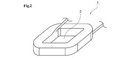
- the coil 1 has an air core part 2 as shown in FIG.
- the press machine 10 has a fixing member 11 that penetrates the air core 2 of the coil 1 at a predetermined processing position. That is, the coil 1 is set at a predetermined processing position of the press machine 10 so that the fixing member 11 penetrates the air core part 2.
- the press machine 10 includes a fixing member 11, an upper pressing portion 12, a lower pressing portion 13, a front pressing portion 14, a rear pressing portion 15, a left pressing portion 16, and a right pressing portion 17. Consists of.
- the upper pressing part 12 and the lower pressing part 13 press the coil 1 in the Z-axis direction (vertical direction).
- the front pressing part 14 and the rear pressing part 15 press the coil 1 in the Y-axis direction (front-rear direction).
- the left part pressing part 16 and the right part pressing part 17 press the coil 1 in the X direction (left and right direction).
- FIG. 10 As shown in FIG.
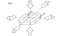
- the direction of each pressing with respect to the coil 1 is the Z-axis direction in the direction orthogonal to the winding direction of the coil 1, and one direction orthogonal to the Z-axis direction is the X-axis direction (or Y-axis).
- the direction perpendicular to the Z-axis direction and the X-axis direction (or Y-axis direction) is the Y-axis direction (or X-axis direction).
- the pressing portions of the X, Y, and Z axes are driven independently.
- various drive mechanisms such as a hydraulic type and a pneumatic type, can be used.
- the step of sequentially pressing is a first step of pressing from the direction orthogonal to the winding direction of the coil 1 (that is, the Z-axis direction).
- a third step of performing press working from a direction orthogonal to the processing direction that is, the Y-axis direction (or X-axis direction)
- a step of performing the first step or the second and third steps a plurality of times while changing the press movement dimension may be provided.
- Patent Document 1 In the method for manufacturing a high-density coil disclosed in Patent Document 1, the vertical and horizontal two directions are pressed. Patent Document 1 does not describe changing pressing conditions such as pressing force and pressing time in the vertical direction and the horizontal direction. For this reason, in the manufacturing method of patent document 1, it presumes that a coil is pressed simultaneously on the same conditions from two directions, vertical and horizontal.
- the cross-section of the coil to be manufactured is a rectangular parallelepiped shape, even if the vertical direction and the horizontal direction are pressed simultaneously under substantially the same conditions, the shape of the object to be pressed is approximately the same, and thus it can be manufactured.
- the cross section of the coil to be manufactured has a tapered shape, the pressed condition needs to be changed because the shape of the pressed object is different in the vertical direction and the horizontal direction.
- FIG. 4 shows a coil 1a having a tapered cross section.
- FIG. 5 is a cross-sectional view of the coil 1a taken along the line AA 'before being pressed in the coil 1a shown in FIG.
- the cross section of the coil 1a before the press work includes gap portions 20, 21, and 22 where no round copper wire exists with respect to a predetermined taper angle ( ⁇ °).
- the main purpose of pressing in the Z-axis direction (vertical direction), which is the first step, is to deform the round copper wire by pressing to place the copper wire in the X-axis direction (left-right direction) or the Y-axis direction (front-rear direction).
- the gaps 20, 21, and 22 are filled out.
- the gap portions 20, 21, and 22 shown in FIG. 5 are filled with the deformed round copper wire as shown in FIG.
- the coil 1a is pressed from the X-axis direction (left-right direction) (or Y-axis direction (front-back direction)), which is the second step.
- the main purpose of pressing in the X-axis direction (left-right direction) (or Y-axis direction (front-rear direction)), which is the second step, is to deform the round copper wire by pressing in the X-axis direction (or Y-axis direction).
- it is to be formed into a taper shape which is a final target.
- the coil 1a is formed into a taper shape that is the final target in the X-axis direction (or Y-axis direction).
- the coil 1a is pressed from the Y-axis direction (front-rear direction) (or X-axis direction (left-right direction)), which is the third step.
- the main purpose of pressing in the Y-axis direction (front-rear direction) (or X-axis direction (left-right direction)), which is the third step, is to deform the round copper wire by pressing in the Y-axis direction (or X-axis direction).
- it is to be formed into a taper shape which is a final target.
- the coil 1a is shape
- the pressing force and pressing time from each axial direction are inevitably different.
- the pressing force from the Z-axis direction is applied to all of the many round copper wires laminated in the Z-axis direction.
- the pressing force from the X-axis direction and the Y-axis direction only needs to be enough to push the round copper wire protruding from the target taper angle range into the X-axis direction and the Y-axis direction. . Therefore, the pressing force from the Z-axis direction may be larger than the pressing force from the X-axis direction and the Y-axis direction.
- the pressing force from the Z-axis direction may be larger than the pressing force from the X-axis direction and the Y-axis direction, the degree of deformation of the round copper wire due to pressing may also increase. At this time, if the deformation of the round copper wire proceeds rapidly, the round copper wire may be damaged. Therefore, it is preferable that the time required to perform pressing from the Z-axis direction is longer than the time required to perform pressing from the X-axis direction and the Y-axis direction. Thereby, rapid deformation of the round copper wire can be avoided.
- (1) Reason 1 The shape drawn by the solid line in FIG. 8 is the shape before the coil 1a is pressed, and the shape drawn by the broken line is the shape after the coil 1a is pressed. Moreover, in the example of FIG. 9, the thickness d1 of the left part pressing part 16 and the right part pressing part 17 (or the front part pressing part 14 and the rear part pressing part 15) is higher than the height d2 of the shape after the coil 1a is pressed. large.
- the pressing from the Z-axis direction and the pressing from the X-axis direction are advanced at the same time, before the upper pressing portion 12 completes the pressing of the coil 1a, the left-side pressing The part 16 and the right part pressing part 17 (or the front part pressing part 14 and the rear part pressing part 15) enter between the upper pressing part 12 and the lower pressing part 13 and prevent the pressing. For this reason, after finishing pressing from one axial direction, it is necessary to provide a time difference so as to perform pressing from the other axial direction.
- the step of setting the coils 1 and 1a at a predetermined processing position of the press machine 10 and the setting at the predetermined processing position are included, so that it is possible to cope with the manufacture of high-density coils having various cross-sectional shapes.
- the above-described embodiment can be variously modified without departing from the gist thereof.
- the coil 1a having a tapered cross section is exemplified.
- the high-density coil manufacturing method according to the embodiment of the present invention can cope with various other cross-sectional shapes.
- R can be provided at the corners of the tapered shape in the cross section of the coil 1a.
- it may be a donut-shaped coil whose cross-sectional shape is a circle or an ellipse.
- the order of the pressing process from the X-axis direction and the pressing process from the Y-axis direction in the above-described embodiment may be appropriately switched.
Landscapes
- Engineering & Computer Science (AREA)
- Power Engineering (AREA)
- Manufacturing & Machinery (AREA)
- Manufacture Of Motors, Generators (AREA)
Abstract
様々な断面形状の高密度コイルの製造に対応すること。 本発明は、コイル1をプレス加工して形成する高密度コイルの製造方法において、コイル1をプレス加工機10の所定の加工位置にセットするステップと、所定の加工位置にセットされた状態のコイル1に対し、時間差をおいて複数の方向から順次プレス加工を施すステップと、を有するものである。
Description
本発明は、高密度コイルの製造方法に関する。
丸銅線の完全整列巻きにおいて、丸銅線にダメージを与えずに高い占積率にすることができる高密度コイルの製造方法が開示されている(特許文献1参照)。特許文献1の製造方法では、伸び率30~40%の丸銅線を完全整列巻きし、150℃~230℃で加熱押圧することで丸銅線間の空隙部分を埋めて占積率を高めている。
特許文献1の製造方法では、垂直および水平の二方向から同じ条件でコイルを押圧するため、断面が直方体形状である高密度コイルしか製造できなかった。一方、断面がテーパー形状であるなど、様々な断面形状の高密度コイルの需要がある。このような断面が直方体形状ではない高密度コイルの製造については特許文献1の製造方法では対応できない。
本発明は、このような背景の下に行われたものであって、様々な断面形状の高密度コイルの製造に対応することができる高密度コイルの製造方法を提供することを目的とする。
本発明は、コイルをプレス加工して形成する高密度コイルの製造方法において、コイルをプレス加工機の所定の加工位置にセットするステップと、所定の加工位置にセットされた状態のコイルに対し、時間差をおいて複数の方向から順次プレス加工を施すステップと、を有するものである。
上述の高密度コイルの製造方法において、順次プレス加工を施すステップは、コイルの巻線方向に直交する方向からプレス加工を施す第一のステップと、第一のステップにおけるプレス加工の方向に直交する1つの方向からプレス加工を施す第二のステップと、第一および第二のステップにおけるプレス加工の方向に直交する方向からプレス加工を施す第三のステップと、を有することができる。
このとき、第一のステップまたは第二および第三のステップを複数回、プレス移動寸法を変えながら行うステップを有することができる。
本発明によれば、様々な断面形状の高密度コイルの製造に対応することができる。
(概要について)
本発明の実施の形態に係る高密度コイルの製造方法は、図1に示すように、コイル1をプレス加工機10の所定の加工位置にセットするステップと、所定の加工位置にセットされた状態のコイル1に対し、時間差をおいて複数の方向X,Y,Zから順次プレス加工を施すステップと、を有する。
本発明の実施の形態に係る高密度コイルの製造方法は、図1に示すように、コイル1をプレス加工機10の所定の加工位置にセットするステップと、所定の加工位置にセットされた状態のコイル1に対し、時間差をおいて複数の方向X,Y,Zから順次プレス加工を施すステップと、を有する。
(プレス加工機10の所定の加工位置について)
コイル1は、図2に示すように、空芯部2を有する。プレス加工機10の所定の加工位置には、図1に示すように、コイル1の空芯部2を貫通する固定部材11を有する。すなわち、コイル1は、固定部材11が空芯部2を貫通するようにしてプレス加工機10の所定の加工位置にセットされる。
コイル1は、図2に示すように、空芯部2を有する。プレス加工機10の所定の加工位置には、図1に示すように、コイル1の空芯部2を貫通する固定部材11を有する。すなわち、コイル1は、固定部材11が空芯部2を貫通するようにしてプレス加工機10の所定の加工位置にセットされる。
(プレス加工機10について)
プレス加工機10は、図1に示すように、固定部材11、上部押圧部12、下部押圧部13、前部押圧部14、後部押圧部15、左部押圧部16、および右部押圧部17により構成される。上部押圧部12および下部押圧部13は、コイル1をZ軸方向(上下方向)に押圧する。前部押圧部14および後部押圧部15は、コイル1をY軸方向(前後方向)に押圧する。左部押圧部16および右部押圧部17は、コイル1をX方向(左右方向)に押圧する。コイル1に対する各押圧の方向は、図3に示すように、コイル1の巻線方向に直交する方向がZ軸方向であり、Z軸方向に直交する1つの方向がX軸方向(またはY軸方向)であり、Z軸方向およびX軸方向(またはY軸方向)に直交する方向がY軸方向(またはX軸方向)である。このとき、X,Y,Zの各軸の押圧部は、それぞれ独立して駆動される。なお、各押圧部の駆動機構についてはどのようなものであってもよいので、図示および説明は省略するが、油圧式や空圧式など、様々な駆動機構を用いることができる。
プレス加工機10は、図1に示すように、固定部材11、上部押圧部12、下部押圧部13、前部押圧部14、後部押圧部15、左部押圧部16、および右部押圧部17により構成される。上部押圧部12および下部押圧部13は、コイル1をZ軸方向(上下方向)に押圧する。前部押圧部14および後部押圧部15は、コイル1をY軸方向(前後方向)に押圧する。左部押圧部16および右部押圧部17は、コイル1をX方向(左右方向)に押圧する。コイル1に対する各押圧の方向は、図3に示すように、コイル1の巻線方向に直交する方向がZ軸方向であり、Z軸方向に直交する1つの方向がX軸方向(またはY軸方向)であり、Z軸方向およびX軸方向(またはY軸方向)に直交する方向がY軸方向(またはX軸方向)である。このとき、X,Y,Zの各軸の押圧部は、それぞれ独立して駆動される。なお、各押圧部の駆動機構についてはどのようなものであってもよいので、図示および説明は省略するが、油圧式や空圧式など、様々な駆動機構を用いることができる。
(押圧順序について)
本発明の実施の形態に係る高密度コイルの製造方法において、順次プレス加工を施すステップは、コイル1の巻線方向に直交する方向(すなわち、Z軸方向)からプレス加工を施す第一のステップと、第一のステップにおけるプレス加工の方向に直交する1つの方向(すなわち、X軸方向(またはY軸方向))からプレス加工を施す第二のステップと、第一および第二のステップにおけるプレス加工の方向に直交する方向(すなわち、Y軸方向(またはX軸方向))からプレス加工を施す第三のステップと、を有する。このとき、第一のステップまたは第二および第三のステップを複数回、プレス移動寸法を変えながら行うステップを有するようにしてもよい。
本発明の実施の形態に係る高密度コイルの製造方法において、順次プレス加工を施すステップは、コイル1の巻線方向に直交する方向(すなわち、Z軸方向)からプレス加工を施す第一のステップと、第一のステップにおけるプレス加工の方向に直交する1つの方向(すなわち、X軸方向(またはY軸方向))からプレス加工を施す第二のステップと、第一および第二のステップにおけるプレス加工の方向に直交する方向(すなわち、Y軸方向(またはX軸方向))からプレス加工を施す第三のステップと、を有する。このとき、第一のステップまたは第二および第三のステップを複数回、プレス移動寸法を変えながら行うステップを有するようにしてもよい。
(従来例との比較)
特許文献1に開示された高密度コイルの製造方法では、垂直、水平二方向を押圧する。特許文献1には、垂直方向と水平方向とで押圧力や押圧時間などの押圧条件を変更することについては記載されていない。このため、特許文献1の製造方法では、垂直および水平の二方向から同じ条件で同時にコイルを押圧すると類推する。
特許文献1に開示された高密度コイルの製造方法では、垂直、水平二方向を押圧する。特許文献1には、垂直方向と水平方向とで押圧力や押圧時間などの押圧条件を変更することについては記載されていない。このため、特許文献1の製造方法では、垂直および水平の二方向から同じ条件で同時にコイルを押圧すると類推する。
製造するコイルの断面が直方体形状であれば、垂直方向と水平方向とでほぼ同じ条件で同時に押圧しても、被押圧対象の形状がほぼ同じであるので製造可能である。しかしながら、製造するコイルの断面がテーパー形状を有するような場合、垂直方向と水平方向とでは被押圧対象の形状が異なるため、押圧する条件を変更する必要がある。
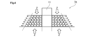
断面がテーパー形状を有するコイル1aを図4に示す。図4に示すコイル1aにおいて、プレス加工を施す前のコイル1aのA-A′線断面図を図5に示す。プレス加工を施す前のコイル1aの断面には、所定のテーパー角度(α°)に対し、丸銅線が存在しない隙間部分20,21,22が含まれる。第一のステップであるZ軸方向(上下方向)の押圧の主な目的は、押圧によって丸銅線を変形させてX軸方向(左右方向)またはY軸方向(前後方向)に丸銅線をはみ出させ、隙間部分20,21,22を埋めることにある。これにより、図5に示す隙間部分20,21,22は、図6に示すように、変形した丸銅線によって埋まることとなる。
続いて、図7に示すように、第二のステップであるX軸方向(左右方向)(またはY軸方向(前後方向))からコイル1aを押圧する。第二のステップであるX軸方向(左右方向)(またはY軸方向(前後方向))の押圧の主な目的は、押圧によって丸銅線を変形させてX軸方向(またはY軸方向)に対して最終的な目標とされるテーパー形状に成形することにある。これにより、コイル1aは、X軸方向(またはY軸方向)に対して最終的な目標とされるテーパー形状に成形される。
最後に、第三のステップであるY軸方向(前後方向)(またはX軸方向(左右方向))からコイル1aを押圧する。第三のステップであるY軸方向(前後方向)(またはX軸方向(左右方向))の押圧の主な目的は、押圧によって丸銅線を変形させてY軸方向(またはX軸方向)に対して最終的な目標とされるテーパー形状に成形することにある。これにより、コイル1aは、Z軸方向、X軸方向、およびY軸方向の全てに対して最終的な目標とされる形状に成形される。
以上説明したような工程では、各軸方向からの押圧の目的が異なる。また、各軸方向からみた被押圧対象の形状も異なる。したがって、各軸方向からの押圧力および押圧時間についても必然的に異なる。たとえば、Z軸方向からの押圧力は、Z軸方向に積層された多数の丸銅線の全てに対して均等な押圧力がかかることが好ましい。これに対し、X軸方向およびY軸方向からの押圧力は、目標とするテーパー角度の範囲からはみ出した分の丸銅線をX軸方向およびY軸方向に押し込めるだけの押圧力があれば良い。したがって、Z軸方向からの押圧力はX軸方向およびY軸方向からの押圧力に比べて大きくする場合がある。
また、Z軸方向からの押圧力はX軸方向およびY軸方向からの押圧力に比べて大きくする場合があるので、押圧による丸銅線の変形の度合も大きくなる場合がある。このとき、丸銅線の変形が急激に進行すると、丸銅線に損傷が生じることもある。よって、Z軸方向からの押圧を行うのに要する時間は、X軸方向およびY軸方向からの押圧を行うのに要する時間よりも長くすることが好ましい。これにより、丸銅線の急激な変形を避けることができる。
以上説明したように、特許文献1に開示されている高密度コイルの製造方法のように、垂直および水平の二方向から同じ押圧条件によって同時に押圧を行うことによっては、テーパー形状などの立方体形状ではない断面を有するコイル1aを製造することは難しい。
(各軸方向からの押圧に時間差を設けることについて)
上述の工程において、一つの軸方向からの押圧を終えた後に、他の軸方向からの押圧を行うように時間差を設けている。その理由については、以下の二つの理由がある。
上述の工程において、一つの軸方向からの押圧を終えた後に、他の軸方向からの押圧を行うように時間差を設けている。その理由については、以下の二つの理由がある。
(1)理由その1
図8の実線で描いた形状がコイル1aのプレス加工前の形状であり、破線で描いた形状がコイル1aのプレス加工後の形状である。また、図9の例では、左部押圧部16および右部押圧部17(または前部押圧部14および後部押圧部15)の厚みd1がコイル1aのプレス加工後の形状の高さd2よりも大きい。このような状況下では、Z軸方向からの押圧とX軸方向(またはY軸方向)からの押圧を同時に進行させると、上部押圧部12がコイル1aの押圧を完了する以前に、左部押圧部16および右部押圧部17(または前部押圧部14および後部押圧部15)が上部押圧部12と下部押圧部13との間に入り込み押圧を阻止してしまう。このため、一つの軸方向からの押圧を終えた後に、他の軸方向からの押圧を行うように時間差を設けることが必要になる。
図8の実線で描いた形状がコイル1aのプレス加工前の形状であり、破線で描いた形状がコイル1aのプレス加工後の形状である。また、図9の例では、左部押圧部16および右部押圧部17(または前部押圧部14および後部押圧部15)の厚みd1がコイル1aのプレス加工後の形状の高さd2よりも大きい。このような状況下では、Z軸方向からの押圧とX軸方向(またはY軸方向)からの押圧を同時に進行させると、上部押圧部12がコイル1aの押圧を完了する以前に、左部押圧部16および右部押圧部17(または前部押圧部14および後部押圧部15)が上部押圧部12と下部押圧部13との間に入り込み押圧を阻止してしまう。このため、一つの軸方向からの押圧を終えた後に、他の軸方向からの押圧を行うように時間差を設けることが必要になる。
(2)理由その2
図10の例では、左部押圧部16および右部押圧部17(または前部押圧部14および後部押圧部15)の厚みd3がコイル1aのプレス加工後の形状の高さd4と等しく設定されている。このため、図9の例で説明したような問題は発生しない。しかしながら、図10の例では、Z軸方向からの押圧によって、コイル1aの丸銅線が変形し、X軸方向(またはY軸方向)にはみ出した部分3がX軸方向(またはY軸方向)から進行して来る左部押圧部16および右部押圧部17(または前部押圧部14および後部押圧部15)の先端部に乗り上げてしまい、断線などの損傷が発生する問題がある。このため、一つの軸方向からの押圧を終えた後に、他の軸方向からの押圧を行うように時間差を設けることが必要になる。
図10の例では、左部押圧部16および右部押圧部17(または前部押圧部14および後部押圧部15)の厚みd3がコイル1aのプレス加工後の形状の高さd4と等しく設定されている。このため、図9の例で説明したような問題は発生しない。しかしながら、図10の例では、Z軸方向からの押圧によって、コイル1aの丸銅線が変形し、X軸方向(またはY軸方向)にはみ出した部分3がX軸方向(またはY軸方向)から進行して来る左部押圧部16および右部押圧部17(または前部押圧部14および後部押圧部15)の先端部に乗り上げてしまい、断線などの損傷が発生する問題がある。このため、一つの軸方向からの押圧を終えた後に、他の軸方向からの押圧を行うように時間差を設けることが必要になる。
(本発明の実施の形態に係る効果について)
以上説明したように、本発明の実施の形態に係る高密度コイルの製造方法によれば、コイル1,1aをプレス加工機10の所定の加工位置にセットするステップと、所定の加工位置にセットされた状態のコイル1,1aに対し、時間差をおいて複数の方向から順次プレス加工を施すステップと、を有するので、様々な断面形状の高密度コイルの製造に対応することができる。
以上説明したように、本発明の実施の形態に係る高密度コイルの製造方法によれば、コイル1,1aをプレス加工機10の所定の加工位置にセットするステップと、所定の加工位置にセットされた状態のコイル1,1aに対し、時間差をおいて複数の方向から順次プレス加工を施すステップと、を有するので、様々な断面形状の高密度コイルの製造に対応することができる。
(その他の実施の形態)
上述した実施の形態は、その要旨を逸脱しない限り、様々に変更が可能である。上述の実施の形態では、断面がテーパー形状のコイル1aを例示したが、本発明の実施の形態に係る高密度コイルの製造方法は、その他にも様々な断面形状に対応が可能である。たとえば、コイル1aの断面におけるテーパー形状の角部にRを設けることもできる。または、断面形状が円または楕円のドーナツ型のコイルであってもよい。
上述した実施の形態は、その要旨を逸脱しない限り、様々に変更が可能である。上述の実施の形態では、断面がテーパー形状のコイル1aを例示したが、本発明の実施の形態に係る高密度コイルの製造方法は、その他にも様々な断面形状に対応が可能である。たとえば、コイル1aの断面におけるテーパー形状の角部にRを設けることもできる。または、断面形状が円または楕円のドーナツ型のコイルであってもよい。
また、上述の実施の形態におけるX軸方向からの押圧工程とY軸方向からの押圧工程とは適宜順番を入れ替えてもよい。
1,1a…コイル、2…空芯部、10…プレス加工機、11…固定部材、12…上部押圧部、13…下部押圧部、14…前部押圧部、15…後部押圧部、16…左部押圧部、17…右部押圧部
Claims (3)
- コイルをプレス加工して形成する高密度コイルの製造方法において、
前記コイルをプレス加工機の所定の加工位置にセットするステップと、
前記所定の加工位置にセットされた状態の前記コイルに対し、時間差をおいて複数の方向から順次プレス加工を施すステップと、
を有する、
ことを特徴とする高密度コイルの製造方法。 - 請求項1記載の高密度コイルの製造方法において、
前記順次プレス加工を施すステップは、
前記コイルの巻線方向に直交する方向からプレス加工を施す第一のステップと、
前記第一のステップにおけるプレス加工の方向に直交する1つの方向からプレス加工を施す第二のステップと、
前記第一および第二のステップにおけるプレス加工の方向に直交する方向からプレス加工を施す第三のステップと、
を有する、
ことを特徴とする高密度コイルの製造方法。 - 請求項2記載の高密度コイルの製造方法において、
前記第一のステップまたは前記第二および第三のステップを複数回、プレス移動寸法を変えながら行うステップを有する、
ことを特徴とする高密度コイルの製造方法。
Priority Applications (4)
| Application Number | Priority Date | Filing Date | Title |
|---|---|---|---|
| EP17777147.4A EP3432329B1 (en) | 2017-05-22 | 2017-05-22 | Production method for high-density coil |
| CN201780001166.7A CN109313980B (zh) | 2017-05-22 | 2017-05-22 | 高密度线圈的制造方法 |
| PCT/JP2017/019026 WO2018216065A1 (ja) | 2017-05-22 | 2017-05-22 | 高密度コイルの製造方法 |
| US15/567,278 US10679789B2 (en) | 2017-05-22 | 2017-05-22 | Method of manufacturing high-density coil |
Applications Claiming Priority (1)
| Application Number | Priority Date | Filing Date | Title |
|---|---|---|---|
| PCT/JP2017/019026 WO2018216065A1 (ja) | 2017-05-22 | 2017-05-22 | 高密度コイルの製造方法 |
Publications (1)
| Publication Number | Publication Date |
|---|---|
| WO2018216065A1 true WO2018216065A1 (ja) | 2018-11-29 |
Family
ID=64272629
Family Applications (1)
| Application Number | Title | Priority Date | Filing Date |
|---|---|---|---|
| PCT/JP2017/019026 Ceased WO2018216065A1 (ja) | 2017-05-22 | 2017-05-22 | 高密度コイルの製造方法 |
Country Status (4)
| Country | Link |
|---|---|
| US (1) | US10679789B2 (ja) |
| EP (1) | EP3432329B1 (ja) |
| CN (1) | CN109313980B (ja) |
| WO (1) | WO2018216065A1 (ja) |
Cited By (1)
| Publication number | Priority date | Publication date | Assignee | Title |
|---|---|---|---|---|
| JP2024011498A (ja) * | 2022-07-14 | 2024-01-25 | 株式会社デンソー | 回転電機 |
Families Citing this family (2)
| Publication number | Priority date | Publication date | Assignee | Title |
|---|---|---|---|---|
| CN112563019B (zh) * | 2020-12-08 | 2022-05-13 | 湖南承运机电有限公司 | 一种带脱卷功能的绕卷装置 |
| DE102021127189A1 (de) | 2021-10-20 | 2023-04-20 | Schaeffler Technologies AG & Co. KG | Verfahren und Vorrichtung zur Verdichtung von Spulenwindungen von segmentierten Statoren |
Citations (4)
| Publication number | Priority date | Publication date | Assignee | Title |
|---|---|---|---|---|
| JPS5617006A (en) * | 1979-07-21 | 1981-02-18 | Meiji Natl Ind Co Ltd | Manufacture of stabilizer for discharge lamp |
| JP2004193395A (ja) * | 2002-12-12 | 2004-07-08 | Okayama Giken:Kk | 高密度コイル |
| JP2005072428A (ja) | 2003-08-27 | 2005-03-17 | Selco Co Ltd | 高密度コイルの製造方法 |
| JP2014093492A (ja) * | 2012-11-06 | 2014-05-19 | Toshiba Corp | 超電導コイルの製造装置および製造方法ならびに超電導コイル |
Family Cites Families (9)
| Publication number | Priority date | Publication date | Assignee | Title |
|---|---|---|---|---|
| GB1079815A (en) * | 1964-02-03 | 1967-08-16 | Gen Electric | Improvements in electrical coils and methods for producing same |
| TW355868B (en) * | 1995-01-30 | 1999-04-11 | Seikosha Kk | Line binding structure for coil winding terminals along the winding axis |
| JP2007267463A (ja) * | 2006-03-28 | 2007-10-11 | Hitachi Ltd | 回転電機及び回転電機の製造方法 |
| JP4234749B2 (ja) * | 2006-10-19 | 2009-03-04 | 株式会社日立製作所 | 回転電機、クランク形状の連続巻きコイル、分布巻き固定子及びそれらの形成方法 |
| JP4613918B2 (ja) | 2007-03-12 | 2011-01-19 | トヨタ自動車株式会社 | コイルの製造方法 |
| US7472468B2 (en) * | 2007-04-03 | 2009-01-06 | Yeadon Energy Systems, Inc. | Method for winding brushless DC motors |
| CN201498327U (zh) * | 2009-04-29 | 2010-06-02 | 陈骏逸 | 供磁性组件使用的微型线圈 |
| CN204633497U (zh) * | 2012-09-28 | 2015-09-09 | 株式会社安川电机 | 线圈、旋转电机及直线电机 |
| GB201417355D0 (en) * | 2014-10-01 | 2014-11-12 | Univ Newcastle | Method and system for manufacture of a compressed coil |
-
2017
- 2017-05-22 EP EP17777147.4A patent/EP3432329B1/en not_active Not-in-force
- 2017-05-22 CN CN201780001166.7A patent/CN109313980B/zh not_active Expired - Fee Related
- 2017-05-22 US US15/567,278 patent/US10679789B2/en active Active
- 2017-05-22 WO PCT/JP2017/019026 patent/WO2018216065A1/ja not_active Ceased
Patent Citations (4)
| Publication number | Priority date | Publication date | Assignee | Title |
|---|---|---|---|---|
| JPS5617006A (en) * | 1979-07-21 | 1981-02-18 | Meiji Natl Ind Co Ltd | Manufacture of stabilizer for discharge lamp |
| JP2004193395A (ja) * | 2002-12-12 | 2004-07-08 | Okayama Giken:Kk | 高密度コイル |
| JP2005072428A (ja) | 2003-08-27 | 2005-03-17 | Selco Co Ltd | 高密度コイルの製造方法 |
| JP2014093492A (ja) * | 2012-11-06 | 2014-05-19 | Toshiba Corp | 超電導コイルの製造装置および製造方法ならびに超電導コイル |
Non-Patent Citations (1)
| Title |
|---|
| See also references of EP3432329A4 |
Cited By (2)
| Publication number | Priority date | Publication date | Assignee | Title |
|---|---|---|---|---|
| JP2024011498A (ja) * | 2022-07-14 | 2024-01-25 | 株式会社デンソー | 回転電機 |
| JP7841375B2 (ja) | 2022-07-14 | 2026-04-07 | 株式会社デンソー | 回転電機の製造方法 |
Also Published As
| Publication number | Publication date |
|---|---|
| CN109313980B (zh) | 2020-12-01 |
| CN109313980A (zh) | 2019-02-05 |
| EP3432329B1 (en) | 2022-04-27 |
| US20180336997A1 (en) | 2018-11-22 |
| US10679789B2 (en) | 2020-06-09 |
| EP3432329A1 (en) | 2019-01-23 |
| EP3432329A4 (en) | 2020-01-08 |
Similar Documents
| Publication | Publication Date | Title |
|---|---|---|
| KR102069972B1 (ko) | 적층 코어 제조 장치 | |
| JP5255648B2 (ja) | 曲り部材の製造方法、バンパーリインフォースメントの製造方法、曲げ加工装置およびバンパーリインフォースメントの製造装置 | |
| US10679789B2 (en) | Method of manufacturing high-density coil | |
| JP2017183626A (ja) | 高密度コイルの製造方法 | |
| JP6860947B1 (ja) | 段付き中空シャフトの製造方法、及びモータシャフトの製造方法 | |
| US9362808B2 (en) | Method of manufacturing rotor core of electric rotating machine | |
| CN105290301B (zh) | 一种多向异形轴颈锻造方法 | |
| JP5863270B2 (ja) | リング状素形材の製造方法 | |
| JP2011235323A (ja) | 車両用のスタビライザ製造装置と製造方法 | |
| CN108011477A (zh) | 定子的制造方法和马达 | |
| US20190115811A1 (en) | Method of manufacturing laminated core | |
| JP2016128189A (ja) | 自然時効する合金からなるワークの成形方法 | |
| KR101473230B1 (ko) | 사각용기의 딥 드로잉방법 | |
| KR102067706B1 (ko) | 전기모터의 베어링 쉴드 제조방법 | |
| KR102797762B1 (ko) | 와이어 성형 장치 및 방법 | |
| JP6572866B2 (ja) | コイル成形装置 | |
| JP2005199338A (ja) | Cvjインナーレースの鍛造方法、鍛造装置およびcvjインナーレース | |
| CN207782622U (zh) | 发电机转子绕线工装 | |
| KR102365295B1 (ko) | 금속을 반복하여 가공하는 방법 | |
| JP2015229189A (ja) | ワッシャ製造方法 | |
| US8037731B2 (en) | Forging method and forging apparatus | |
| JP2018023204A (ja) | 電機子巻線の型取り用治具及びその作製方法 | |
| KR101294160B1 (ko) | 폐단면을 구비한 보강재 성형장치 및 이를 이용한 보강재 제작방법 | |
| CN102357817A (zh) | 蝶阀板的新型加工胎具及其加工工艺 | |
| JP2017192244A (ja) | 回転電機の積層鉄心、および回転電機の積層鉄心の製造方法 |
Legal Events
| Date | Code | Title | Description |
|---|---|---|---|
| WWE | Wipo information: entry into national phase |
Ref document number: 15567278 Country of ref document: US |
|
| 121 | Ep: the epo has been informed by wipo that ep was designated in this application |
Ref document number: 17777147 Country of ref document: EP Kind code of ref document: A1 |
|
| NENP | Non-entry into the national phase |
Ref country code: DE |
|
| NENP | Non-entry into the national phase |
Ref country code: JP |