WO2018216159A1 - 燃料電池セル - Google Patents
燃料電池セル Download PDFInfo
- Publication number
- WO2018216159A1 WO2018216159A1 PCT/JP2017/019496 JP2017019496W WO2018216159A1 WO 2018216159 A1 WO2018216159 A1 WO 2018216159A1 JP 2017019496 W JP2017019496 W JP 2017019496W WO 2018216159 A1 WO2018216159 A1 WO 2018216159A1
- Authority
- WO
- WIPO (PCT)
- Prior art keywords
- modification
- peripheral edge
- outer peripheral
- electrode layer
- boundary
- Prior art date
- Legal status (The legal status is an assumption and is not a legal conclusion. Google has not performed a legal analysis and makes no representation as to the accuracy of the status listed.)
- Ceased
Links
Images









Classifications
-
- H—ELECTRICITY
- H01—ELECTRIC ELEMENTS
- H01M—PROCESSES OR MEANS, e.g. BATTERIES, FOR THE DIRECT CONVERSION OF CHEMICAL ENERGY INTO ELECTRICAL ENERGY
- H01M8/00—Fuel cells; Manufacture thereof
- H01M8/24—Grouping of fuel cells, e.g. stacking of fuel cells
- H01M8/241—Grouping of fuel cells, e.g. stacking of fuel cells with solid or matrix-supported electrolytes
- H01M8/2425—High-temperature cells with solid electrolytes
-
- H—ELECTRICITY
- H01—ELECTRIC ELEMENTS
- H01M—PROCESSES OR MEANS, e.g. BATTERIES, FOR THE DIRECT CONVERSION OF CHEMICAL ENERGY INTO ELECTRICAL ENERGY
- H01M4/00—Electrodes
- H01M4/86—Inert electrodes with catalytic activity, e.g. for fuel cells
- H01M4/8605—Porous electrodes
- H01M4/8626—Porous electrodes characterised by the form
-
- H—ELECTRICITY
- H01—ELECTRIC ELEMENTS
- H01M—PROCESSES OR MEANS, e.g. BATTERIES, FOR THE DIRECT CONVERSION OF CHEMICAL ENERGY INTO ELECTRICAL ENERGY
- H01M4/00—Electrodes
- H01M4/86—Inert electrodes with catalytic activity, e.g. for fuel cells
- H01M4/8636—Inert electrodes with catalytic activity, e.g. for fuel cells with a gradient in another property than porosity
-
- H—ELECTRICITY
- H01—ELECTRIC ELEMENTS
- H01M—PROCESSES OR MEANS, e.g. BATTERIES, FOR THE DIRECT CONVERSION OF CHEMICAL ENERGY INTO ELECTRICAL ENERGY
- H01M4/00—Electrodes
- H01M4/86—Inert electrodes with catalytic activity, e.g. for fuel cells
- H01M4/8636—Inert electrodes with catalytic activity, e.g. for fuel cells with a gradient in another property than porosity
- H01M4/8642—Gradient in composition
-
- H—ELECTRICITY
- H01—ELECTRIC ELEMENTS
- H01M—PROCESSES OR MEANS, e.g. BATTERIES, FOR THE DIRECT CONVERSION OF CHEMICAL ENERGY INTO ELECTRICAL ENERGY
- H01M8/00—Fuel cells; Manufacture thereof
- H01M8/02—Details
- H01M8/0202—Collectors; Separators, e.g. bipolar separators; Interconnectors
- H01M8/023—Porous and characterised by the material
- H01M8/0232—Metals or alloys
-
- H—ELECTRICITY
- H01—ELECTRIC ELEMENTS
- H01M—PROCESSES OR MEANS, e.g. BATTERIES, FOR THE DIRECT CONVERSION OF CHEMICAL ENERGY INTO ELECTRICAL ENERGY
- H01M8/00—Fuel cells; Manufacture thereof
- H01M8/02—Details
- H01M8/0271—Sealing or supporting means around electrodes, matrices or membranes
- H01M8/028—Sealing means characterised by their material
- H01M8/0282—Inorganic material
-
- H—ELECTRICITY
- H01—ELECTRIC ELEMENTS
- H01M—PROCESSES OR MEANS, e.g. BATTERIES, FOR THE DIRECT CONVERSION OF CHEMICAL ENERGY INTO ELECTRICAL ENERGY
- H01M8/00—Fuel cells; Manufacture thereof
- H01M8/10—Fuel cells with solid electrolytes
- H01M8/12—Fuel cells with solid electrolytes operating at high temperature, e.g. with stabilised ZrO2 electrolyte
- H01M8/1213—Fuel cells with solid electrolytes operating at high temperature, e.g. with stabilised ZrO2 electrolyte characterised by the electrode/electrolyte combination or the supporting material
-
- H—ELECTRICITY
- H01—ELECTRIC ELEMENTS
- H01M—PROCESSES OR MEANS, e.g. BATTERIES, FOR THE DIRECT CONVERSION OF CHEMICAL ENERGY INTO ELECTRICAL ENERGY
- H01M8/00—Fuel cells; Manufacture thereof
- H01M8/10—Fuel cells with solid electrolytes
- H01M8/12—Fuel cells with solid electrolytes operating at high temperature, e.g. with stabilised ZrO2 electrolyte
- H01M8/1213—Fuel cells with solid electrolytes operating at high temperature, e.g. with stabilised ZrO2 electrolyte characterised by the electrode/electrolyte combination or the supporting material
- H01M8/1226—Fuel cells with solid electrolytes operating at high temperature, e.g. with stabilised ZrO2 electrolyte characterised by the electrode/electrolyte combination or the supporting material characterised by the supporting layer
-
- H—ELECTRICITY
- H01—ELECTRIC ELEMENTS
- H01M—PROCESSES OR MEANS, e.g. BATTERIES, FOR THE DIRECT CONVERSION OF CHEMICAL ENERGY INTO ELECTRICAL ENERGY
- H01M4/00—Electrodes
- H01M4/86—Inert electrodes with catalytic activity, e.g. for fuel cells
- H01M2004/8678—Inert electrodes with catalytic activity, e.g. for fuel cells characterised by the polarity
- H01M2004/8684—Negative electrodes
-
- H—ELECTRICITY
- H01—ELECTRIC ELEMENTS
- H01M—PROCESSES OR MEANS, e.g. BATTERIES, FOR THE DIRECT CONVERSION OF CHEMICAL ENERGY INTO ELECTRICAL ENERGY
- H01M8/00—Fuel cells; Manufacture thereof
- H01M8/10—Fuel cells with solid electrolytes
- H01M8/12—Fuel cells with solid electrolytes operating at high temperature, e.g. with stabilised ZrO2 electrolyte
- H01M2008/1293—Fuel cells with solid oxide electrolytes
-
- Y—GENERAL TAGGING OF NEW TECHNOLOGICAL DEVELOPMENTS; GENERAL TAGGING OF CROSS-SECTIONAL TECHNOLOGIES SPANNING OVER SEVERAL SECTIONS OF THE IPC; TECHNICAL SUBJECTS COVERED BY FORMER USPC CROSS-REFERENCE ART COLLECTIONS [XRACs] AND DIGESTS
- Y02—TECHNOLOGIES OR APPLICATIONS FOR MITIGATION OR ADAPTATION AGAINST CLIMATE CHANGE
- Y02E—REDUCTION OF GREENHOUSE GAS [GHG] EMISSIONS, RELATED TO ENERGY GENERATION, TRANSMISSION OR DISTRIBUTION
- Y02E60/00—Enabling technologies; Technologies with a potential or indirect contribution to GHG emissions mitigation
- Y02E60/30—Hydrogen technology
- Y02E60/50—Fuel cells
Definitions
- the present invention relates to a fuel battery cell.
- This unit for fuel cell stack has a porous metal support.
- the support includes a seal having a seal depth extending from an upper surface thereof to at least a bottom surface thereof.
- the seal is also disposed along the periphery of the porous metal support and is impermeable to gas moving in the plane of the porous metal support. Furthermore, the seal is made by local melting.
- the present invention has been made in view of such problems of the conventional technology. And an object of this invention is to provide the fuel cell which can maintain gas-barrier property favorably.
- the present inventor has intensively studied to achieve the above object. As a result, the inventors have found that the above object can be achieved by providing an anode electrode layer having a predetermined electrode reaction portion and an outer peripheral edge portion, and have completed the present invention.
- FIG. 1 is an exploded perspective view of a fuel battery cell for explaining the first embodiment.
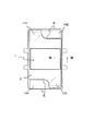
- FIG. 2 is a plan view of the fuel cell.
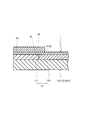
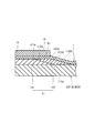
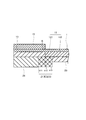
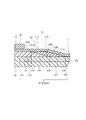
- FIG. 3 is a cross-sectional view taken along line III-III of an example of the fuel cell shown in FIG.
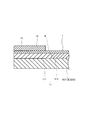
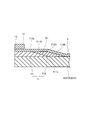
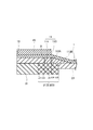
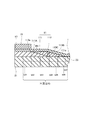
- FIG. 4 is a cross-sectional view of a main part of a first modified example of the fuel battery cell illustrating the first embodiment.
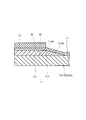
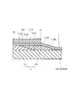
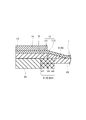
- FIG. 5 is a cross-sectional view of a main part of a second modified example of the fuel battery cell illustrating the first embodiment.
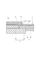
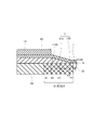
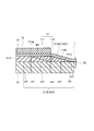
- FIG. 6 is a cross-sectional view of a main part of an example of a fuel battery cell for explaining the second embodiment.
- FIG. 7 is a cross-sectional view of a main part of a first modified example of the fuel battery cell illustrating the second embodiment.
- FIG. 8 is a cross-sectional view of a main part of a second modified example of the fuel battery cell illustrating the second embodiment.
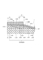
- FIG. 9 is a cross-sectional view of a main part of an example of a fuel battery cell for explaining the third embodiment.
- FIG. 10 is a cross-sectional view of a main part of a first modified example of the fuel battery cell illustrating the third embodiment.
- FIG. 11 is a cross-sectional view of a main part of a second modified example of the fuel battery cell illustrating the third embodiment.
- FIG. 12 is a cross-sectional view of a main part of a third modified example of the fuel battery cell illustrating the third embodiment.
- FIG. 13 is sectional drawing of the principal part of the 4th modification of the fuel cell explaining 3rd Embodiment.
- FIG. 14 is a cross-sectional view of a main part of an example of a fuel battery cell for explaining the fourth embodiment.
- FIG. 15 is a cross-sectional view of a main part of first to fifth modifications of the fuel battery cell illustrating the fourth embodiment.
- FIG. 16 is a cross-sectional view of a main part of sixth to eighth modifications of the fuel battery cell for explaining the fourth embodiment.
- FIG. 17 is a cross-sectional view of a main part of the ninth to thirteenth modified examples of the fuel battery cell illustrating the fourth embodiment.
- FIG. 14 is a cross-sectional view of a main part of an example of a fuel battery cell for explaining the fourth embodiment.
- FIG. 15 is a cross-sectional view of a main part of first to fifth modifications of the fuel battery cell illustrating the fourth embodiment.
- FIG. 16 is a cross-sectional view of a main part of sixth
- FIG. 18 is a cross-sectional view of the main parts of the fourteenth to eighteenth modified examples of the fuel battery cell illustrating the fourth embodiment.
- FIG. 19 is a cross-sectional view of the main part of the nineteenth to twenty-first modifications of the fuel cell, explaining the fourth embodiment.
- FIG. 20 is a cross-sectional view of a main part of the twenty-second to twenty-sixth modified examples of the fuel battery cell illustrating the fourth embodiment.
- FIG. 21 is a cross-sectional view of the main part of the twenty-seventh to thirty-fifth modified examples of the fuel battery cell illustrating the fourth embodiment.
- FIG. 22 is a cross-sectional view of a main part of 36th to 44th modified examples of the fuel battery cell illustrating the fourth embodiment.
- FIG. 23 is a cross-sectional view of a main part of the 45th to 51st modifications of the fuel cell illustrating the fourth embodiment.
- FIG. 24 is a cross-sectional view of a main part of the 52nd to 58th modified examples of the fuel battery cell for explaining the fourth embodiment.
- FIG. 25 is a cross-sectional view of a main part of the 59th to 67th modified examples of the fuel battery cell for explaining the fourth embodiment.
- FIG. 1 is an exploded perspective view of a fuel battery cell for explaining the first embodiment.
- FIG. 2 is a plan view of the fuel battery cell. In addition, in FIG. 2, the separator is not shown.
- the fuel battery cell FC of the present embodiment includes a battery structure 1, a metal support plate 2 that supports the battery structure 1, and the battery structure 1 and the support plate 2.
- a pair of separators 3 and 3 forming a gas flow path is provided.
- the fuel cell FC is a preferred form in which the metal support plate 2 is used to increase the mechanical strength while ensuring gas permeability, and is sometimes referred to as a metal support cell.
- a solid oxide fuel cell can be mentioned as a suitable example.
- the support plate 2 provided with the battery structure 1 and the pair of separators 3 and 3 have a rectangular shape having equivalent vertical and horizontal dimensions. Is preferred.
- the fuel battery cell FC of the present embodiment has a gas that circulates a cathode gas (air) between one separator 3 and a cathode electrode layer, which will be described in detail later, on the battery structure 1. It is preferable to have a flow path. Further, as shown in FIGS. 1 and 2, the fuel battery cell FC of the present embodiment includes an anode gas between the other separator 3 and an anode electrode layer and a support plate 2, which will be described in detail later. It is preferable to have a gas flow path for circulating (fuel gas).
- the fuel cell FC of the present embodiment includes an anode gas supply manifold hole H ⁇ b> 1 on one short side of the support plate 2 and the pair of separators 3 and 3, and It is preferable that each has a cathode gas discharge manifold hole H2. Further, as shown in FIGS. 1 and 2, the fuel cell FC of the present embodiment includes an anode gas discharge manifold hole H3 on the other short side of the support plate 2 and the pair of separators 3 and 3, and It is preferable that each has a manifold hole H4 for supplying cathode gas.
- manifold holes H1 to H4 form manifolds that communicate with each other when the cell structure 1 and the separator 3 are stacked to form a fuel cell stack.
- the cell structures 1 adjacent to each other in the stacking direction share one separator 3 therebetween.
- the fuel cell FC of this embodiment preferably has a seal member S between the outer peripheral portions of the support plate 2 and each separator 3 or around the manifold holes H1 to H4 (FIG. 1). And FIG. 2). Thereby, the airtightness of the gas flow path is ensured.
- the seal member S is not arranged or an open portion is provided in a part of the seal member S so that the gas corresponding to each gas flow path can flow (FIG. 1). And FIG. 2).
- the fuel cell FC described above supplies anode gas to an anode electrode layer, which will be described later in detail, and supplies cathode gas to a cathode electrode layer, which will be described later, in detail. Then, electric energy is generated by an electrochemical reaction in each electrode layer. At this time, the anode gas is supplied to the anode electrode layer, which will be described later in detail, from the battery structure 1 through the main body, which will be described later, in detail.
- FIG. 3 is a cross-sectional view taken along line III-III of an example of the fuel cell shown in FIG.
- the battery structure 1 includes an anode electrode layer (fuel electrode layer) 11, an electrolyte layer 13 made of a solid electrolyte,
- the cathode electrode layer (air electrode layer) 15 has a structure in which the layers are sequentially laminated.
- the anode electrode layer 11 is disposed in the center and has an electrode reaction part 111 having a thermal expansion coefficient larger than that of the electrolyte layer, and is adjacent to the electrode reaction part 111 on the outer periphery of the electrode reaction part 111.
- an outer peripheral edge portion 113 that is disposed and has a thermal expansion coefficient smaller than that of the electrode reaction section 111.
- thermal expansion coefficient for example, an average linear expansion coefficient measured by a method based on JIS Z 2285 or JIS R 1618 can be applied.
- the operating temperature of the fuel cell is about 600 ° C. to 900 ° C. Therefore, although not particularly limited, for example, as the thermal expansion coefficient, it is preferable to apply an average linear expansion coefficient at 800 ° C.
- the metal support plate 2 supplements the strength of the battery structure 1 and the support plate itself.
- the battery structure 1 is disposed on the anode electrode layer 11 side.
- the support plate may be disposed on the cathode electrode layer side.
- fuel cells not provided with a support plate are included in the scope of the present invention.
- the metal support plate 2 at the illustrated position may be any of a main body portion 21 and a frame portion 23 described later in detail. Further, the metal support plate at the illustrated position may be a main body portion and a frame portion having a not-shown boundary between a main body portion and a frame portion, which will be described in detail later.
- a battery structure having a structure in which an anode electrode layer, an electrolyte layer, and a cathode electrode layer are laminated, the anode electrode layer is disposed in the center, and the electrolyte layer
- An electrode reaction part having a larger thermal expansion coefficient than the thermal expansion coefficient, and an outer peripheral edge part disposed adjacent to the electrode reaction part on the outer periphery of the electrode reaction part and having a smaller thermal expansion coefficient than the electrode reaction part It was set as the structure which has.
- the tensile breakage of the electrolyte layer that may occur with the thermal expansion of the electrode reaction part that is relatively easy to thermally expand, the outer peripheral edge part that is relatively difficult to thermally expand the outer periphery of the electrode reaction part and the electrode reaction part By arranging them adjacent to each other, they can be effectively suppressed or prevented. As a result, the gas barrier property in the fuel battery cell can be maintained well.
- the battery structure further includes a metal support plate that is disposed on the anode electrode layer side and supports the battery structure.
- the outer peripheral edge portion and the electrolyte layer have different one or both of the component components and the component content.
- the thickness of the outer peripheral edge portion 113 is the same as the thickness of the electrode reaction portion 111 at least in the vicinity of the boundary B between the outer peripheral edge portion 113 and the electrode reaction portion 111. It is preferable that
- “in the vicinity of the boundary between the outer peripheral edge and the electrode reaction part” in this specification is a range from the boundary between the outer peripheral edge and the electrode reaction part to a position where the influence of thermal expansion of the electrode reaction part can be almost ignored. Can be mentioned. This range can be appropriately set by, for example, preliminary experiments.
- a flat electrolyte layer can be provided particularly in a portion where a thermal stress difference is likely to occur.
- the gas barrier property in the fuel battery cell can be maintained well.
- At least a part of the inner edge side of the outer peripheral edge portion 113 has a structure in which a flat surface is formed on the electrolyte layer 13 side together with the electrode reaction portion 111. It is preferable that In addition, what is necessary is just to make at least one part of the inner edge side of the outer periphery part 113 the boundary B vicinity of the outer periphery part and electrode reaction part mentioned above, for example. Moreover, it is preferable that at least a part of the inner edge side of the outer peripheral edge 113 is a part where the cathode electrode layers are partially overlapped when viewed in a plan view, for example.
- the inner edge side of the outer peripheral edge 113 is a part where a part of the main body part is overlapped when viewed in a plan view.
- the whole outer peripheral part may have the structure which formed the flat surface on the electrolyte layer side with the electrode reaction part.
- a flat electrolyte layer can be provided particularly in a region where a thermal stress difference is likely to occur.
- the gas barrier property in the fuel battery cell can be maintained well.
- the outer peripheral edge portion and the electrode reaction portion each include an anode catalyst and a solid electrolyte, and the content ratio of the anode catalyst in the outer peripheral edge portion is less than the content ratio of the anode catalyst in the electrode reaction portion.
- a configuration is preferable.
- the outer peripheral edge portion 113 preferably has a structure having a portion 113 ⁇ / b> A that is disposed so as to overlap the cathode electrode layer 15 when viewed in plan.
- the boundary between the members of the anode electrode layer and the boundary between the members of the cathode electrode layer and the space are shifted, and stress concentration due to the thermal stress difference can be suppressed or prevented.
- the gas barrier property in the fuel battery cell can be maintained well.
- This also causes the boundary between the anode electrode layer member and the cathode electrode layer member and the space to deviate and cause bending deformation of the electrolyte layer that may occur due to thermal expansion of the electrode reaction portion. Can be effectively suppressed or prevented physically compared to a case where the electrode layer does not have a portion that overlaps with the cathode electrode layer when viewed in plan. As a result, the gas barrier property in the fuel battery cell can be maintained well.
- the component of the electrode reaction part 111 in the anode electrode layer 11 is not particularly limited as long as the thermal expansion coefficient of the electrode reaction part is larger than the thermal expansion coefficient of the electrolyte layer.
- a cermet composed of nickel (Ni) and yttria stabilized zirconia (YSZ) can be used.
- the component of the outer peripheral edge 113 in the anode electrode layer 11 is not particularly limited as long as the outer peripheral edge has a smaller thermal expansion coefficient than the electrode reaction section. That is, in the outer peripheral edge, for example, the electrode reaction may proceed or the electrode reaction may not proceed. In addition, for example, it is preferable to apply an outer peripheral edge portion that is different from an electrolyte layer, which will be described later, and a component component and a component content ratio. Furthermore, when an outer peripheral part contains the same anode catalyst and solid electrolyte as an electrode reaction part, what has a smaller content ratio of the anode catalyst of an outer peripheral part than an anode catalyst content rate of an electrode reaction part is mentioned as a suitable example. be able to.
- the outer peripheral edge is a cermet made of nickel and yttria-stabilized zirconia
- a preferable example is one in which the nickel content in the outer peripheral edge is smaller than the nickel content in the electrode reaction part.
- nickel (Ni) which is an example of an outer periphery part and yttria stabilized zirconia (YSZ) is 11.0. ⁇ 10 ⁇ 6 / K.
- the constituent components of the electrolyte layer 13 are not particularly limited, and examples thereof include solid electrolytes such as 8 mol% yttria stabilized zirconia (8 mol% YSZ).
- YSZ yttria-stabilized zirconia
- the constituent component of the electrolyte layer preferably has oxide ion conductivity.
- the electrolyte layer preferably covers the entire anode electrode layer.
- the component of the component of the cathode electrode layer 15 is not particularly limited.
- the fuel cell is a solid oxide fuel cell, for example, lanthanum strontium cobalt iron oxide (LSCF) or the like. Can be mentioned.
- LSCF lanthanum strontium cobalt iron oxide
- yttria stabilized zirconia YSZ
- LSCF lanthanum strontium cobalt iron oxide
- a ceria-based material is interposed between the electrolyte layer and the cathode electrode layer. It is preferable to provide a diffusion prevention layer containing an oxide.
- the metal support plate 2 is not particularly limited, and for example, a porous metal member such as a sintered metal body or a foam metal body can be applied.
- the metal support plate is not particularly limited, but is made of a porous metal member such as a sintered metal body or a foamed metal body.
- a part of the porous metal member is crushed in the thickness direction by pressing to be densely formed.
- the metal support plate is not particularly limited, but a preferable example is one having a flat surface on the anode electrode layer side.
- FIG. 4 is a cross-sectional view of a main part of a first modified example of the fuel battery cell illustrating the first embodiment.
- FIG. 5 is a cross-sectional view of a main part of a second modified example of the fuel battery cell illustrating the first embodiment.
- the same components as those in the first embodiment are denoted by the same reference numerals, and detailed description thereof is omitted.
- the first modification shown in FIG. 4 and the second modification shown in FIG. 5 are different from the example shown in FIG. 3 in the position of the boundary B between the outer peripheral edge 113 and the electrode reaction part 111. That is, in the first modification shown in FIG. 4, the outer end of the cathode electrode layer 15 and the boundary B overlap each other when viewed in plan. Further, in the second modification shown in FIG. 5, the boundary B is arranged outside the outer end of the cathode electrode layer 15 when viewed in plan.
- the example shown in FIG. 3 and the second modification shown in FIG. 5 are preferable to the first modification shown in FIG. . Further, as described above, from the viewpoint of suppressing the bending deformation of the electrolyte layer that may be caused by the thermal expansion of the electrode reaction part, the example shown in FIG. 3 is more preferable than the second modification shown in FIG. Is preferred.
- FIG. 6 is a cross-sectional view of a main part of an example of a fuel battery cell for explaining the second embodiment. That is, FIG. 6 is a cross-sectional view of the fuel battery cell at substantially the same position as the position along the line III-III shown in FIG.
- the same components as those in the first embodiment are denoted by the same reference numerals, and detailed description thereof is omitted.
- the configuration in which the outer peripheral edge portion 113 has a portion 113B whose thickness gradually decreases toward the outer end side is different from the above-described embodiment.
- a metal support plate that is disposed on the anode electrode layer side of the battery structure and supports the battery structure.
- the outer peripheral edge portion and the electrolyte layer have different constituent elements and constituent contents or one or both of them.
- the thickness of the outer peripheral edge 113 is the same as the thickness of the electrode reaction part 111 at least in the vicinity of the boundary B between the outer peripheral edge 113 and the electrode reaction part 111. It is preferable that
- a flat electrolyte layer can be provided particularly in a portion where a thermal stress difference is likely to occur.
- the gas barrier property in the fuel battery cell can be maintained well.
- At least a part of the inner edge side of the outer peripheral edge portion 113 has a structure in which a flat surface is formed on the electrolyte layer 13 side together with the electrode reaction portion 111. It is preferable that In addition, what is necessary is just to make at least one part of the inner edge side of the outer periphery part 113 the boundary B vicinity of the outer periphery part and electrode reaction part mentioned above, for example. Moreover, it is preferable that at least a part of the inner edge side of the outer peripheral edge 113 is a part where the cathode electrode layers are partially overlapped when viewed in a plan view, for example. Furthermore, it is preferable that at least a part of the inner edge side of the outer peripheral edge 113 is a part where a part of the main body part is overlapped when viewed in a plan view.
- a flat electrolyte layer can be provided particularly in a region where a thermal stress difference is likely to occur.
- the gas barrier property in the fuel battery cell can be maintained well.
- the outer peripheral edge part and the electrode reaction part each include an anode catalyst and a solid electrolyte, and the content ratio of the anode catalyst in the outer peripheral edge part is smaller than the content ratio of the anode catalyst in the electrode reaction part.
- a configuration is preferable.
- the outer peripheral edge portion 113 has a portion 113 ⁇ / b> A that is disposed so as to overlap the cathode electrode layer 15 when viewed in plan.
- the boundary between the members of the anode electrode layer and the boundary between the members of the cathode electrode layer and the space are shifted, and stress concentration due to the thermal stress difference can be suppressed or prevented.
- the gas barrier property in the fuel battery cell can be maintained well.
- This also causes the boundary between the anode electrode layer member and the cathode electrode layer member and the space to deviate and cause bending deformation of the electrolyte layer that may occur due to thermal expansion of the electrode reaction portion. Can be effectively suppressed or prevented physically compared to a case where the electrode layer does not have a portion that overlaps with the cathode electrode layer when viewed in plan. As a result, the gas barrier property in the fuel battery cell can be maintained well.
- FIG. 7 is a cross-sectional view of a main part of a first modified example of the fuel battery cell illustrating the second embodiment.
- FIG. 8 is a cross-sectional view of a main part of a second modified example of the fuel battery cell illustrating the second embodiment.
- the boundary B between the outer peripheral edge portion 113 and the electrode reaction portion 111 are different from the example shown in FIG. 6 in the position of the boundary B between the outer peripheral edge portion 113 and the electrode reaction portion 111. That is, in the first modification shown in FIG. 7, the outer end of the cathode electrode layer 15 and the boundary B overlap each other when viewed in plan. Further, in the second modification shown in FIG. 8, the boundary B is arranged outside the outer end of the cathode electrode layer 15 when viewed in plan. Further, in the second modified example shown in FIG. 8, a part 113B of the outer peripheral edge portion whose thickness gradually decreases toward the outer end side in the example shown in FIG. 6 is directed toward the outer end side described in detail later.
- the thickness is gradually reduced and the tip is replaced with a part 111A of the electrode reaction part 111 arranged on the support plate 2 side, and a part 113B of the outer peripheral edge part is arranged outside thereof.
- the outer peripheral edge 113 in the second modified example does not necessarily have to gradually decrease in thickness toward the outer end side.
- the example shown in FIG. 6 and the second modification shown in FIG. 8 are preferable to the first modification shown in FIG. . Further, as described above, from the viewpoint of suppressing the bending deformation of the electrolyte layer that may occur with the thermal expansion of the electrode reaction part, the example shown in FIG. 6 is more preferable than the second modification shown in FIG. Is preferred.
- FIG. 9 is a cross-sectional view of a main part of an example of a fuel battery cell for explaining the third embodiment. That is, FIG. 9 is a cross-sectional view of the fuel battery cell at substantially the same position as the position along the line III-III shown in FIG.
- the outer peripheral edge portion 113 is gradually thinned toward the inner end side, and the tip 113a is disposed on the electrolyte layer 13 side.
- the electrode reaction portion 111 gradually decreases in thickness toward the outer end side, and the tip 111a has a portion 111A disposed on the side opposite to the electrolyte layer 13, in other words, on the support plate 2 side.
- the configuration it has is different from the embodiment described above.
- the boundary B1 between the outer peripheral edge portion 113 and the electrode reaction portion 111 is inclined with respect to the thickness direction of the anode electrode layer 11.
- the outer peripheral edge portion that is relatively difficult to thermally expand is disposed on the electrolyte layer side, thereby suppressing or preventing thermal expansion on the electrolyte side.
- the gas barrier property in the fuel battery cell can be maintained well.
- the electrode reaction part that is relatively easily thermally expanded is arranged on the support plate side, so that the difference in thermal expansion between the support plate and the anode electrode layer is alleviated, and microscopic peeling is suppressed or prevented. The As a result, the gas barrier property in the fuel battery cell can be maintained well.
- a metal support plate that is disposed on the anode electrode layer side of the battery structure and supports the battery structure.
- the outer peripheral edge portion and the electrolyte layer have different constituent elements and constituent contents or one or both of them.
- At least a part of the inner edge side of the outer peripheral edge portion 113 has a structure in which a flat surface is formed on the electrolyte layer 13 side together with the electrode reaction portion 111. It is preferable that
- a flat electrolyte layer can be provided particularly in a region where a thermal stress difference is likely to occur.
- the gas barrier property in the fuel battery cell can be maintained well.
- the outer peripheral edge portion and the electrode reaction portion each include an anode catalyst and a solid electrolyte, and the content ratio of the anode catalyst in the outer peripheral edge portion is smaller than the content ratio of the anode catalyst in the electrode reaction portion.
- a configuration is preferable.
- the outer peripheral edge portion 113 has a portion 113 ⁇ / b> A that is disposed so as to overlap the cathode electrode layer 15 when viewed in plan.
- the boundary between the members of the anode electrode layer and the boundary between the members of the cathode electrode layer and the space are shifted, and stress concentration due to the thermal stress difference can be suppressed or prevented.
- the gas barrier property in the fuel battery cell can be maintained well.
- This also causes the boundary between the anode electrode layer member and the cathode electrode layer member and the space to deviate and cause bending deformation of the electrolyte layer that may occur due to thermal expansion of the electrode reaction portion. Can be effectively suppressed or prevented physically compared to a case where the electrode layer does not have a portion that overlaps with the cathode electrode layer when viewed in plan. As a result, the gas barrier property in the fuel battery cell can be maintained well.
- the outer peripheral edge portion 113 has a portion 113 ⁇ / b> B whose thickness gradually decreases toward the outer end side.
- FIG. 10 is a cross-sectional view of a main part of a first modified example of the fuel battery cell illustrating the third embodiment.
- FIG. 11 is a cross-sectional view of a main part of a second modified example of the fuel battery cell illustrating the third embodiment.
- FIG. 12 is a cross-sectional view of a main part of a third modified example of the fuel battery cell illustrating the third embodiment.
- FIG. 13 is sectional drawing of the principal part of the 4th modification of the fuel cell explaining 3rd Embodiment.
- the first modification shown in FIG. 10 to the fourth modification shown in FIG. 13 are different from the example shown in FIG. 9 in the position of the boundary B1 between the outer peripheral edge 113 and the electrode reaction part 111. That is, in the first modification shown in FIG. 10, the outer end of the cathode electrode layer 15 is disposed on the inner side of the inner end 113 a of the outer peripheral edge 113 when viewed in plan. In the second modification shown in FIG. 11, the outer end of the cathode electrode layer 15 and the inner tip 113 a of the outer peripheral edge portion 113 overlap each other when viewed in plan. Furthermore, in the third modification shown in FIG.
- the outer end of the cathode electrode layer 15 and the outer end 111a of the electrode reaction part 111 are arranged so as to overlap each other when viewed in plan. Furthermore, in the fourth modified example shown in FIG. 13, the outer end of the cathode electrode layer 15 is disposed outside the tip 111 a outside the electrode reaction part 111 when viewed in plan.
- the first modification shown in FIG. 10 and the second modification shown in FIG. As described above, from the viewpoint of suppressing the bending deformation of the electrolyte layer that may occur due to the thermal expansion of the electrode reaction part, the first modification shown in FIG. 10 and the second modification shown in FIG. Also, the example shown in FIG. 9, the third modification shown in FIG. 12, and the fourth modification shown in FIG. 13 are considered suitable. Further, from the viewpoint of suppressing the stress concentration due to the thermal stress difference, the example shown in FIG. 9 and the fourth modification shown in FIG. 13 are considered preferable to the third modification shown in FIG. . Note that it is preferable that the example shown in FIG. 9 and the fourth modification shown in FIG. 13 are appropriately selected depending on the difference in the constituent materials of the anode electrode layer.
- FIG. 14 is a cross-sectional view of a main part of an example of a fuel battery cell for explaining the fourth embodiment. That is, FIG. 14 is a cross-sectional view of the fuel battery cell at substantially the same position as the position along the line III-III shown in FIG.
- the metal support plate 2 is gas permeable and has a central main body 21 in contact with the electrode reaction part 111 of the anode electrode layer 11. And the structure which has the flame
- the frame portion 23 is thinner than the main body portion 21.
- a support plate is not particularly limited, but for example, by pressing a porous metal plate portion such as a sintered metal body or a foam metal body having a constant thickness, a portion to be a frame portion is formed. It can be obtained by crushing in the thickness direction to form a dense material.
- the outer peripheral edge portion 113 has a portion 113D that is disposed so as to overlap the main body portion 21 when viewed in plan. .
- the boundary between the parts of the support and the boundary between the members of the anode layer are shifted, and the stress concentration due to the thermal stress difference can be suppressed or prevented.
- the gas barrier property in the fuel battery cell can be maintained well.
- the outer peripheral edge portion and the electrolyte layer have different constituent elements and constituent contents or one or both of them.
- the thickness of the outer peripheral edge portion 113 is the same as the thickness of the electrode reaction portion 111 at least near the boundary B between the outer peripheral edge portion 113 and the electrode reaction portion 111. It is preferable that
- a flat electrolyte layer can be provided particularly in a portion where a thermal stress difference is likely to occur.
- the gas barrier property in the fuel battery cell can be maintained well.
- At least a part of the inner edge side of the outer peripheral edge portion 113 has a structure in which a flat surface is formed on the electrolyte layer 13 side together with the electrode reaction portion 111. It is preferable that In addition, what is necessary is just to make at least one part of the inner edge side of the outer periphery part 113 the boundary B vicinity of the outer periphery part and electrode reaction part mentioned above, for example. Moreover, it is preferable that at least a part of the inner edge side of the outer peripheral edge 113 is a part where the cathode electrode layers are partially overlapped when viewed in a plan view, for example. Furthermore, it is preferable that at least a part of the inner edge side of the outer peripheral edge 113 is a part where a part of the main body part is overlapped when viewed in a plan view.
- a flat electrolyte layer can be provided particularly in a region where a thermal stress difference is likely to occur.
- the gas barrier property in the fuel battery cell can be maintained well.
- the outer peripheral edge part and the electrode reaction part each include an anode catalyst and a solid electrolyte, and the content ratio of the anode catalyst in the outer peripheral edge part is smaller than the content ratio of the anode catalyst in the electrode reaction part.
- a configuration is preferable.
- the outer peripheral edge portion 113 has a portion 113 ⁇ / b> A that is disposed so as to overlap the cathode electrode layer 15 when viewed in plan.
- the boundary between the members of the anode electrode layer and the boundary between the members of the cathode electrode layer and the space are shifted, and stress concentration due to the thermal stress difference can be suppressed or prevented.
- the gas barrier property in the fuel battery cell can be maintained well.
- This also causes the boundary between the anode electrode layer member and the cathode electrode layer member and the space to deviate and cause bending deformation of the electrolyte layer that may occur due to thermal expansion of the electrode reaction portion. Can be effectively suppressed or prevented physically compared to a case where the electrode layer does not have a portion that overlaps with the cathode electrode layer when viewed in plan. As a result, the gas barrier property in the fuel battery cell can be maintained well.
- the outer peripheral edge has a portion that gradually decreases in thickness toward the outer end side.
- the outer peripheral edge portion has a portion where the thickness gradually decreases toward the inner end side and the tip is disposed on the electrolyte layer side, and the electrode reaction portion has the outer end portion. It is preferable to have a configuration in which the thickness gradually decreases toward the side, and the tip has a portion disposed on the support plate side.
- the outer peripheral edge portion that is relatively difficult to thermally expand is disposed on the electrolyte layer side, thereby suppressing or preventing thermal expansion on the electrolyte side.
- the gas barrier property in the fuel battery cell can be maintained well.
- the electrode reaction portion that is relatively easy to thermally expand on the support plate side the difference in thermal expansion between the support plate and the anode electrode layer is alleviated, and microscopic peeling is suppressed or prevented. As a result, the gas barrier property in the fuel battery cell can be maintained well.
- FIG. 15 is a cross-sectional view of a main part of first to fifth modifications of the fuel battery cell illustrating the fourth embodiment.
- the first to fourth modified examples shown in FIG. 15 are different from the example shown in FIG. 14 in the position of the boundary between the main body part 21 and the frame part 23.
- the fifth modified example in which the boundary between the main body 21 and the frame part 23 is the boundary b5 corresponds to the example shown in FIG.
- the boundary b1 between the main body 21 and the frame part 23 is arranged on the inner side of the boundary B when viewed in plan.
- the boundary b ⁇ b> 2 between the main body portion 21 and the frame 23 overlaps the boundary B when viewed in plan.
- the boundary b ⁇ b> 3 between the main body 21 and the frame 23 is disposed between the boundary B and the outer end of the cathode electrode layer 15 when viewed in plan.
- the boundary line b ⁇ b> 4 between the main body portion 21 and the frame portion 23 overlaps with the outer end of the cathode electrode layer 15 when viewed in plan.
- the boundary b ⁇ b> 5 between the main body 21 and the frame 23 is disposed outside the outer end of the cathode electrode layer 15 when viewed in plan.
- the first modification, the third modification, and the fifth modification (shown in FIG. 14) than the second modification and the fourth modification.
- the main body 21 is relatively close to the electrode reaction part 111 where the electrochemical reaction proceeds more than the frame part. Therefore, the temperature environment to which the main body portion and the frame portion are exposed may be different.
- the fifth modification (one example shown in FIG. 14) is more preferable than the first and third modifications. It is considered preferable.
- FIG. 16 is a cross-sectional view of a main part of sixth to eighth modified examples of the fuel battery cell illustrating the fourth embodiment.
- the position of the boundary B between the outer peripheral edge portion 113 and the electrode reaction portion 111 is the same as the example shown in FIG. Is different from the example shown in FIG.
- the boundary b11 between the main body portion 21 and the frame portion 23 is disposed inside the boundary B when viewed in plan.
- the boundary b ⁇ b> 12 between the main body 21 and the frame 23 is disposed so as to overlap the boundary B when viewed in plan.
- the boundary b ⁇ b> 13 between the main body portion 21 and the frame 23 is disposed outside the outer end of the cathode electrode layer 15 when viewed in plan.
- the sixth modification example and the eighth modification example are preferable to the seventh modification example from the viewpoint of suppressing the stress concentration due to the thermal stress difference.
- the main body 21 is relatively close to the electrode reaction part 111 where the electrochemical reaction proceeds more than the frame part. Therefore, the temperature environment to which the main body portion and the frame portion are exposed may be different. In such a case, it is considered that the eighth modification is more preferable than the sixth modification from the viewpoint of suppressing stress concentration due to different exposure temperature environments.
- FIG. 17 is a cross-sectional view of the main part of the ninth to thirteenth modified examples of the fuel battery cell for explaining the fourth embodiment.
- the position of the boundary B between the outer peripheral edge part 113 and the electrode reaction part 111 is the same as the example shown in FIG. Is different from the example shown in FIG.
- the boundary b ⁇ b> 21 between the main body portion 21 and the frame portion 23 is disposed on the inner side of the outer end of the cathode electrode layer 15 when viewed in plan.
- the boundary b ⁇ b> 22 between the main body portion 21 and the frame portion 23 is disposed so as to overlap the outer end of the cathode electrode layer 15 when viewed in plan.
- the boundary b ⁇ b> 23 between the main body portion 21 and the frame portion 23 is disposed between the outer end of the cathode electrode layer 15 and the boundary B when viewed in plan.
- the boundary b ⁇ b> 21 between the main body portion 21 and the frame portion 23 is disposed on the inner side of the outer end of the cathode electrode layer 15 when viewed in plan.
- the boundary b ⁇ b> 22 between the main body portion 21 and the frame portion 23 is disposed so as to overlap the outer end of the cathode electrode layer 15 when viewed in plan.
- the boundary b24 between the main body 21 and the frame 23 is arranged so as to overlap the boundary B when viewed in plan. Further, in the thirteenth modification shown in FIG. 17, the boundary b25 between the main body 21 and the frame 23 is disposed outside the boundary B when viewed in plan.
- the ninth modification example, the eleventh modification example, and the thirteenth modification example are more preferable than the tenth modification example and the twelfth modification example from the viewpoint of suppressing the stress concentration due to the thermal stress difference.
- the main body 21 is relatively close to the electrode reaction part 111 where the electrochemical reaction proceeds more than the frame part. Therefore, the temperature environment to which the main body portion and the frame portion are exposed may be different. In such a case, it is considered that the thirteenth modification is more suitable than the ninth modification and the eleventh modification from the viewpoint of suppressing stress concentration due to different exposure temperature environments.
- FIG. 18 is a cross-sectional view of the main part of the fourteenth to eighteenth modified examples of the fuel battery cell illustrating the fourth embodiment.
- the position of the boundary B between the outer peripheral edge portion 113 and the electrode reaction portion 111 is the same as that in the example shown in FIG. Is different from the example shown in FIG.
- the boundary b31 between the main body 21 and the frame part 23 is disposed on the inner side of the boundary B when viewed in plan.
- the boundary b32 between the main body portion 21 and the frame portion 23 is arranged so as to overlap the boundary B when viewed in plan.
- the boundary b33 between the main body portion 21 and the frame portion 23 is disposed between the boundary B and the outer end of the cathode electrode layer 15 when viewed in plan.
- the boundary b ⁇ b> 34 between the main body portion 21 and the frame portion 23 overlaps with the outer end of the cathode electrode layer 15 when viewed in plan. Further, in the eighteenth modification shown in FIG. 18, the boundary b ⁇ b> 35 between the main body portion 21 and the frame portion 23 is disposed outside the outer end of the cathode electrode layer 15 when viewed in plan.
- the fourteenth modification, the sixteenth modification, and the eighteenth modification are more preferable than the fifteenth modification and the seventeenth modification from the viewpoint of suppressing stress concentration due to the thermal stress difference.
- the main body 21 is relatively close to the electrode reaction part 111 where the electrochemical reaction proceeds more than the frame part. Therefore, the temperature environment to which the main body portion and the frame portion are exposed may be different.
- the 18th modification is more preferable than the 14th modification and the 16th modification from the viewpoint of suppressing stress concentration due to different exposure temperature environments.
- the boundary is located at a portion where the anode electrode layer is relatively thick. It is considered that the 14th modification and the 16th modification are suitable.
- FIG. 19 is a cross-sectional view of the main parts of the nineteenth to twenty-first modifications of the fuel battery cell illustrating the fourth embodiment.
- the position of the boundary B between the outer peripheral edge portion 113 and the electrode reaction portion 111 is the same as the example shown in FIG. Is different from the example shown in FIG.
- the boundary b41 between the main body portion 21 and the frame portion 23 is disposed inside the boundary B when viewed in plan.
- the boundary b ⁇ b> 42 between the main body portion 21 and the frame portion 23 is disposed so as to overlap the boundary B when viewed in plan.
- the boundary b43 between the main body 21 and the frame part 23 is disposed outside the boundary B when viewed in plan.
- the nineteenth modification and the twentieth modification are more preferable than the twentieth modification from the viewpoint of suppressing the stress concentration due to the thermal stress difference.
- the main body 21 is relatively close to the electrode reaction part 111 where the electrochemical reaction proceeds more than the frame part. Therefore, the temperature environment to which the main body portion and the frame portion are exposed may be different.
- the twenty-first modification is more preferable than the nineteenth modification from the viewpoint of suppressing stress concentration due to different exposure temperature environments.
- the boundary is located at a portion where the anode electrode layer is relatively thick.
- the 19th variant is also considered suitable.
- FIG. 20 is a cross-sectional view of the main part of the 22nd to 26th modified examples of the fuel battery cell for explaining the fourth embodiment.
- the position of the boundary B between the outer peripheral edge part 113 and the electrode reaction part 111 is the same as the example shown in FIG. Is different from the example shown in FIG.
- the boundary b51 between the main body portion 21 and the frame portion 23 is disposed inside the outer end of the cathode electrode layer 15 when viewed in plan.
- the boundary b ⁇ b> 52 between the main body portion 21 and the frame portion 23 is disposed so as to overlap the outer end of the cathode electrode layer 15 when viewed in plan.
- the boundary b53 between the main body 21 and the frame 23 is disposed between the outer end of the cathode electrode layer 15 and the boundary B when viewed in plan.
- the boundary b54 between the main body portion 21 and the frame portion 23 is disposed so as to overlap the boundary B when viewed in plan. Furthermore, in the twenty-sixth modified example shown in FIG. 20, the boundary b55 between the main body 21 and the frame part 23 is disposed outside the boundary B when viewed in plan.
- the twenty-second, twenty-fourth, and twenty-sixth modified examples are more preferable than the twenty-third and twenty-fifth modified examples from the viewpoint of suppressing stress concentration due to the thermal stress difference.
- the main body 21 is relatively close to the electrode reaction part 111 where the electrochemical reaction proceeds more than the frame part. Therefore, the temperature environment to which the main body portion and the frame portion are exposed may be different.
- the twenty-fourth modification and the twenty-sixth modification are considered preferable to the twenty-second modification from the viewpoint of suppressing stress concentration due to different exposure temperature environments.
- the boundary is located at a portion where the anode electrode layer is relatively thick. It can be considered that the twenty-second modification is more preferable than the example.
- FIG. 21 is a cross-sectional view of a main part of the 27th to 35th modified examples of the fuel battery cell for explaining the fourth embodiment.
- the position of the boundary B1 between the outer peripheral edge part 113 and the electrode reaction part 111 is the same as in the example shown in FIG. Is different from the example shown in FIG.
- the boundary b61 between the main body portion 21 and the frame portion 23 is disposed on the inner side of the tip 113a when viewed in plan.
- the boundary b62 between the main body portion 21 and the frame portion 23 is disposed so as to overlap the tip 113a when viewed in plan.
- the boundary b ⁇ b> 63 between the main body 21 and the frame 23 is disposed between the tip 113 a and the outer end of the cathode electrode layer 15 when viewed in plan.
- the boundary b ⁇ b> 64 between the main body portion 21 and the frame portion 23 overlaps with the outer end of the cathode electrode layer 15 when viewed in plan.
- the boundary b65 between the main body portion 21 and the frame portion 23 is disposed between the outer end of the cathode electrode layer 15 and the tip 111a when viewed in plan.
- the boundary b66 between the main body 21 and the frame 23 is arranged so as to overlap the tip 111a when viewed in plan.
- the boundary b ⁇ b> 67 between the main body portion 21 and the frame portion 23 is disposed between the tip 111 a and the outer end of the anode electrode layer 11 when viewed in plan.
- the boundary b ⁇ b> 68 between the main body portion 21 and the frame portion 23 is disposed so as to overlap the outer end of the anode electrode layer 11 when viewed in plan.
- the boundary b ⁇ b> 69 between the main body portion 21 and the frame portion 23 is disposed outside the outer end of the anode electrode layer 11 when viewed in plan.
- the 27th modification, the 29th modification, the 28th modification, the 30th modification, the 32nd modification, and the 34th modification are suitable.
- the main body 21 is relatively close to the electrode reaction part 111 where the electrochemical reaction proceeds more than the frame part. Therefore, the temperature environment to which the main body portion and the frame portion are exposed may be different.
- the 33rd modification and the 35th modification are more preferable than the 27th modification, the 29th modification, and the 31st modification. Examples are considered suitable.
- the boundary is located at a portion where the anode electrode layer is relatively thick. It is considered that the 27th modification, the 29th modification, and the 31st modification are more suitable than the examples.
- the position of the boundary B1 between the outer peripheral edge part 113 and the electrode reaction part 111 is the same as the example shown in FIG. Is different from the example shown in FIG.
- the boundary b71 between the main body 21 and the frame part 23 is disposed on the inner side of the outer end of the cathode electrode layer 15 when viewed in plan.
- the boundary b ⁇ b> 72 between the main body portion 21 and the frame portion 23 overlaps with the outer end of the cathode electrode layer 15 when viewed in plan.
- the boundary b73 between the main body portion 21 and the frame portion 23 is disposed between the outer end of the cathode electrode layer 15 and the tip 113a when viewed in plan.
- the boundary b74 between the main body portion 21 and the frame portion 23 is arranged so as to overlap with the tip 113a when viewed in plan. Furthermore, in the 40th modification shown in FIG. 22, the boundary b75 between the main body portion 21 and the frame portion 23 is disposed between the tip 113a and the tip 111a when viewed in plan. In the 41st modification shown in FIG. 22, the boundary b76 between the main body portion 21 and the frame portion 23 is disposed so as to overlap the tip 111a when viewed in plan. Further, in the forty-second modification shown in FIG. 22, the boundary b77 between the main body portion 21 and the frame portion 23 is disposed between the tip 111a and the outer end of the anode electrode layer 11 when viewed in plan.
- the boundary b ⁇ b> 78 between the main body portion 21 and the frame portion 23 overlaps with the outer end of the anode electrode layer 11 when viewed in plan. Further, in the forty-fourth modification shown in FIG. 22, the boundary b ⁇ b> 79 between the main body portion 21 and the frame portion 23 is disposed outside the outer end of the anode electrode layer 11 when viewed in plan.
- the 40th modification, the 42nd modification, and the 44th modification are suitable.
- the main body 21 is relatively close to the electrode reaction part 111 where the electrochemical reaction proceeds more than the frame part. Therefore, the temperature environment to which the main body portion and the frame portion are exposed may be different.
- the 42nd modification and the 44th modification are more preferable than the 36th modification, the 38th modification, and the 40th modification. Examples are considered suitable.
- the boundary is located at a portion where the anode electrode layer is relatively thick. It is considered that the 36th modification, the 38th modification, and the 40th modification are more preferable than the examples.
- the position of the boundary B1 between the outer peripheral edge portion 113 and the electrode reaction portion 111 is the same as in the example shown in FIG. Is different from the example shown in FIG.
- the boundary b81 between the main body portion 21 and the frame portion 23 is disposed inside the outer end of the cathode electrode layer 15 when viewed in plan. Further, in the forty-sixth modification example shown in FIG. 23, the boundary b82 between the main body portion 21 and the frame portion 23 is disposed so as to overlap the outer end of the cathode electrode layer 15 when viewed in plan. Further, in the forty-seventh modification example shown in FIG. 23, the boundary b83 between the main body portion 21 and the frame portion 23 is disposed between the outer end of the cathode electrode layer 15 and the tip 111a when viewed in plan. In the forty-eighth modification shown in FIG.
- the boundary b84 between the main body portion 21 and the frame portion 23 is disposed so as to overlap the tip 111a when viewed in plan. Furthermore, in the 49th modification shown in FIG. 23, the boundary b85 between the main body portion 21 and the frame portion 23 is disposed between the tip 111a and the outer end of the anode electrode layer 11 when viewed in plan. In the 50th modification shown in FIG. 23, the boundary b ⁇ b> 86 between the main body portion 21 and the frame portion 23 is disposed so as to overlap the outer end of the anode electrode layer 11 when viewed in plan. Furthermore, in the 51st modification shown in FIG. 23, the boundary b87 between the main body portion 21 and the frame portion 23 is disposed outside the outer end of the anode electrode layer 11 when viewed in plan.
- the 45th modification, the 47th modification, the 49th modification, rather than the 46th modification, the 48th modification, and the 50th modification The 51st modification is suitable.
- the main body 21 is relatively close to the electrode reaction part 111 where the electrochemical reaction proceeds more than the frame part. Therefore, the temperature environment to which the main body portion and the frame portion are exposed may be different.
- the 49th modification and the 51st modification are preferable to the 45th modification and the 47th modification from the viewpoint of suppressing stress concentration due to different exposure temperature environments. it is conceivable that.
- the boundary is located at a portion where the anode electrode layer is relatively thick. It is considered that the 45th and 47th modifications are more suitable than the examples.
- the position of the boundary B1 between the outer peripheral edge portion 113 and the electrode reaction portion 111 is the same as the example shown in FIG. Is different from the example shown in FIG.
- the boundary b91 between the main body portion 21 and the frame portion 23 is arranged on the inner side of the tip 113a when viewed in plan.
- the boundary b92 between the main body portion 21 and the frame portion 23 is arranged so as to overlap the tip 113a when viewed in plan.
- the boundary b93 between the main body 21 and the frame 23 is disposed between the tip 113a and the tip 111a when viewed in plan.
- the boundary b94 between the main body portion 21 and the frame portion 23 is arranged so as to overlap the tip 111a when viewed in plan.
- the boundary b95 between the main body portion 21 and the frame portion 23 is disposed between the tip 111a and the outer end of the anode electrode layer 11 when viewed in plan.
- the boundary b ⁇ b> 96 between the main body portion 21 and the frame portion 23 is disposed so as to overlap the outer end of the anode electrode layer 11 when viewed in plan.
- the boundary b97 between the main body portion 21 and the frame portion 23 is disposed outside the outer end of the anode electrode layer 11 when viewed in plan.
- the 58th modification is suitable.
- the main body 21 is relatively close to the electrode reaction part 111 where the electrochemical reaction proceeds more than the frame part. Therefore, the temperature environment to which the main body portion and the frame portion are exposed may be different.
- the 56th modification and the 58th modification are preferable to the 52nd modification and the 54th modification from the viewpoint of suppressing the stress concentration due to different exposure temperature environments. it is conceivable that.
- the 56th modification and the 58th modification are used from the viewpoint that the boundary is located at a portion where the anode electrode layer is relatively thick. It is considered that the 52nd modification and the 54th modification are preferable to the example.
- the position of the boundary B1 between the outer peripheral edge portion 113 and the electrode reaction portion 111 is the same as the example shown in FIG. Is different from the example shown in FIG.
- the boundary b101 between the main body portion 21 and the frame portion 23 is disposed on the inner side of the tip 113a when viewed in plan.
- the boundary b102 between the main body portion 21 and the frame portion 23 is arranged so as to overlap the tip 113a when viewed in plan.
- the boundary b103 between the main body portion 21 and the frame portion 23 is disposed between the tip 113a and the tip 111a when viewed in plan.
- the boundary b104 between the main body portion 21 and the frame portion 23 is arranged so as to overlap the tip 111a when viewed in plan.
- the boundary b105 between the main body 21 and the frame part 23 is disposed between the tip 111a and the outer end of the anode electrode layer 11 when viewed in plan.
- the boundary b ⁇ b> 106 between the main body portion 21 and the frame portion 23 is disposed so as to overlap the outer end of the anode electrode layer 11 when viewed in plan.
- the boundary b107 between the main body portion 21 and the frame portion 23 is between the outer end of the cathode electrode layer 15 and the outer end of the anode electrode layer 11 when viewed in plan. Has been placed.
- the boundary b108 between the main body portion 21 and the frame portion 23 is disposed so as to overlap the outer end of the anode electrode layer 11 when viewed in plan. Further, in the 67th modification shown in FIG. 25, the boundary b109 between the main body portion 21 and the frame portion 23 is arranged outside the outer end of the anode electrode layer 11 when viewed in plan.
- the 63rd modification, the 65th modification, and the 67th modification are suitable.
- the main body 21 is relatively close to the electrode reaction part 111 where the electrochemical reaction proceeds more than the frame part. Therefore, the temperature environment to which the main body portion and the frame portion are exposed may be different.
- the 65th modification and the 67th modification rather than the 59th modification, the 61st modification, and the 63rd modification. Examples are considered suitable.
- the boundary is located at a portion where the anode electrode layer is relatively thick. It is considered that the 59th modification, the 61st modification, and the 63rd modification are more suitable than the examples.
- the fuel battery cell of each embodiment described above can be manufactured by the following method, for example.
- the manufacturing method of the following fuel cell is an example, and the fuel cell of the present invention is not limited to the one obtained by the following manufacturing method.
- an anode electrode layer forming slurry containing a Ni particle / YSZ particle mixture or the like is applied by screen printing on a porous metal substrate such as a chromium-5 mass% iron alloy as a metal support plate, A coating layer is formed.
- the electrode reaction part is formed by using an anode electrode layer forming slurry having a higher Ni particle content ratio than that of the outer peripheral edge part.
- YSZ yttria-stabilized zirconia
- an electrolyte layer forming slurry containing 8 mol% YSZ particles and the like is applied onto the anode coating layer to form an electrolyte coating layer.
- an anode electrode layer having a predetermined electrode reaction portion and an outer peripheral edge portion and an electrolyte layer are formed on the porous substrate by firing at 1000 ° C. in a reducing atmosphere such as a hydrogen atmosphere.
- a slurry for forming a diffusion prevention layer containing ceria-based oxide particles and the like is applied by screen printing and fired at 1000 ° C. in a reducing atmosphere such as a hydrogen atmosphere. A diffusion prevention layer is formed.
- a cathode electrode layer forming slurry containing lanthanum strontium cobalt iron oxide (LSCF) or the like is applied on the diffusion prevention layer by screen printing, and is fired at 1000 ° C. in a reducing atmosphere such as a hydrogen atmosphere.
- a cathode electrode layer is formed on the diffusion preventing layer.
- the average thermal expansion coefficient at 800 ° C. of the electrode reaction part is 12.5 ⁇ 10 ⁇ 6 / K
- the average thermal expansion coefficient at 800 ° C. of the outer peripheral edge part is 11.0 ⁇ 10 ⁇ 6 / K.
- the average thermal expansion coefficient at 800 ° C. of the electrolyte layer is 10.0 ⁇ 10 ⁇ 6 / K, and a desired fuel cell can be obtained. Note that a cold spray method, a slip cast method, or the like can be applied instead of or together with the screen printing method.
- the configuration described in each of the above-described embodiments is not limited to each embodiment.
- the details of the specifications of various configurations are changed, or the configuration of each embodiment is other than the above-described embodiments. Can be combined.
- FC fuel cell 1 battery structure 2 support plate 11 anode electrode layer 13 electrolyte layer 15 cathode electrode layer 21 body part 23 frame part 111 electrode reaction part 113 outer peripheral edge part
Landscapes
- Chemical & Material Sciences (AREA)
- Chemical Kinetics & Catalysis (AREA)
- Electrochemistry (AREA)
- General Chemical & Material Sciences (AREA)
- Life Sciences & Earth Sciences (AREA)
- Engineering & Computer Science (AREA)
- Manufacturing & Machinery (AREA)
- Sustainable Development (AREA)
- Sustainable Energy (AREA)
- Inorganic Chemistry (AREA)
- Fuel Cell (AREA)
- Inert Electrodes (AREA)
Abstract
燃料電池セルFCは、アノード電極層11、電解質層13及びカソード電極層15が積層された構造を有する電池構造体1を備える。アノード電極層11は、中央に配置され、かつ、電解質層の熱膨張率よりも熱膨張率が大きい電極反応部111と、電極反応部111の外周に電極反応部111と隣接して配置され、かつ、電極反応部111の熱膨張率よりも熱膨張率が小さい外周縁部113と、を有する。燃料電池セルFCは、電池構造体1のアノード電極層11側に配置され、電池構造体1を支持する金属製の支持板2をさらに備える。
Description
本発明は、燃料電池セルに関する。
従来、周囲へのガス漏れが防止されている燃料電池スタック用ユニットが提案されている(特許文献1参照。)。この燃料電池スタック用ユニットは、多孔質の金属支持体を有している。そして、支持体は、それの上方面から少なくともそれの底面まで延在するシール深さを有するシールを備えている。また、シールは、多孔質の金属支持体の周囲に沿って配置され、多孔質の金属支持体の平面において移動するガスに対して不透過性である。さらに、シールは、局部溶融によって作製されている。
しかしながら、特許文献1に記載された燃料電池スタック用ユニットであっても、電解質層が割れるおそれがあり、ガスバリア性を向上させるための改善が必要であった。
本発明は、このような従来技術の有する課題に鑑みてなされたものである。そして、本発明は、ガスバリア性を良好に維持し得る燃料電池セルを提供することを目的とする。
本発明者は、上記目的を達成するため鋭意検討を重ねた。その結果、所定の電極反応部と外周縁部とを有するアノード電極層を備えた構成とすることなどにより、上記目的が達成できることを見出し、本発明を完成するに至った。
本発明によれば、ガスバリア性を良好に維持し得る燃料電池セルを提供することができる。
以下、本発明の一実施形態に係る燃料電池セルについて図面を参照しながら詳細に説明する。なお、以下の実施形態で引用する図面の寸法比率は、説明の都合上誇張されており、実際の比率とは異なる場合がある。
(第1の実施形態)
まず、第1の実施形態に係る燃料電池セルについて図面を参照しながら詳細に説明する。図1は、第1の実施形態を説明する燃料電池セルの分解斜視図である。また、図2は、燃料電池セルの平面図である。なお、図2においては、セパレータを示していない。
まず、第1の実施形態に係る燃料電池セルについて図面を参照しながら詳細に説明する。図1は、第1の実施形態を説明する燃料電池セルの分解斜視図である。また、図2は、燃料電池セルの平面図である。なお、図2においては、セパレータを示していない。
図1に示すように、本実施形態の燃料電池セルFCは、電池構造体1と、電池構造体1を支持する金属製の支持板2と、電池構造体1及び支持板2との間にガス流路を形成する一対のセパレータ3,3とを備えている。なお、この燃料電池セルFCは、金属製の支持板2により、ガス透過性を確保しつつ機械的強度を高めた好適形態であって、メタルサポートセルと称されることがある。また、特に限定されるものではないが、燃料電池としては、固体酸化物形燃料電池を好適例として挙げることができる。
そして、図1に示すように、本実施形態の燃料電池セルFCは、電池構造体1を備えた支持板2、及び一対のセパレータ3,3が、同等の縦横寸法を有する矩形状であることが好ましい。
また、図1に示すように、本実施形態の燃料電池セルFCは、一方のセパレータ3と電池構造体1の詳しくは後述するカソード電極層との間に、カソードガス(空気)を流通させるガス流路を有していることが好ましい。さらに、図1及び図2に示すように、本実施形態の燃料電池セルFCは、他方のセパレータ3と電池構造体1の詳しくは後述するアノード電極層及び支持板2との間に、アノードガス(燃料ガス)を流通させるガス流路を有していることが好ましい。
さらに、図1及び図2に示すように、本実施形態の燃料電池セルFCは、支持板2及び一対のセパレータ3,3の一方の短辺側に、アノードガスの供給用マニホールド穴H1、及びカソードガス排出用マニホールド穴H2をそれぞれ有していることが好ましい。また、図1及び図2に示すように、本実施形態の燃料電池セルFCは、支持板2及び一対のセパレータ3,3の他方の短辺側に、アノードガスの排出用マニホールド穴H3、及びカソードガスの供給用マニホールド穴H4をそれぞれ有していることが好ましい。
なお、これらのマニホールド穴H1~H4は、電池構造体1及びセパレータ3を積層して燃料電池スタックを構成した際に、互いに連通してそれぞれのガスを流通させるマニホールドを形成する。また、燃料電池スタックを構成した場合、積層方向に隣接する電池構造体1同士は、双方の間で1枚のセパレータ3を共有する。
さらに、本実施形態の燃料電池セルFCは、支持板2及び各セパレータ3の外周部同士の間や、マニホールド穴H1~H4の周囲に、シール部材Sを有していることが好ましい(図1及び図2参照。)。これにより、ガス流路の気密性を確保している。なお、マニホールド穴H1~H4の周囲に関しては、各ガス流路に該当するガスが流通し得るように、シール部材Sを配置しないか、又はシール部材Sの一部に開放部分を設ける(図1及び図2参照。)。
そして、上述した燃料電池セルFCは、電池構造体1の詳しくは後述するアノード電極層にアノードガスを供給するとともに、電池構造体1の詳しくは後述するカソード電極層にカソードガスを供給することによって、各電極層における電気化学反応により電気エネルギーを発生する。この際、電池構造体1の詳しくは後述するアノード電極層には、支持板2の詳しくは後述する本体部を通してアノードガスの供給が行われる。
次に、第1の実施形態に係る燃料電池セルの要部について図面を参照しながらさらに詳細に説明する。図3は、図2に示した燃料電池セルの一例のIII-III線に沿った断面図である。
図3に示すように、本実施形態の燃料電池セルFCにおいては、電池構造体1は、図中で下側から、アノード電極層(燃料極層)11、固体電解質からなる電解質層13、及びカソード電極層(空気極層)15が順に積層された構造を有するものである。そして、アノード電極層11は、中央に配置され、かつ、前記電解質層の熱膨張率よりも熱膨張率が大きい電極反応部111と、電極反応部111の外周に電極反応部111と隣接して配置され、かつ、電極反応部111の熱膨張率よりも熱膨張率が小さい外周縁部113とを有している。
ここで、本発明における「熱膨張率」としては、例えば、JIS Z 2285やJIS R 1618に準拠した方法で計測した平均線膨張係数を適用することができる。また、特に限定されるものではないが、例えば、燃料電池セルの運転温度における平均線膨張係数を適用することが好ましい。さらに、例えば、燃料電池セルの運転温度は、600℃~900℃程度である。そのため、特に限定されるものではないが、例えば、熱膨張率としては、800℃における平均線膨張係数を適用することが好ましい。
また、特に限定されるものではないが、図3に示すように、本実施形態の燃料電池セルFCにおいては、金属製の支持板2は、電池構造体1の強度を補うとともに、支持板自体の酸化を防ぐため、電池構造体1のアノード電極層11側に配置されている。なお、本発明においては、図示しないが、電池構造体の強度を補うという支持板の目的だけを考慮すれば、例えば、カソード電極層側に支持板を配置しても構わない。また、図示しないが、支持板を備えない燃料電池セルが、本発明の範囲に含まれることは言うまでもない。さらに、図示した位置における金属製の支持板2は、詳しくは後述する本体部21又はフレーム部23のいずれであってもよい。また、図示した位置における金属製の支持板は、詳しくは後述する本体部とフレーム部との図示しない境界を有する本体部とフレーム部であってもよい。
本実施形態においては、上述したように、アノード電極層、電解質層及びカソード電極層が積層された構造を有する電池構造体を備え、アノード電極層が、中央に配置され、かつ、前記電解質層の熱膨張率よりも熱膨張率が大きい電極反応部と、電極反応部の外周に電極反応部と隣接して配置され、かつ、電極反応部の熱膨張率よりも熱膨張率が小さい外周縁部と、を有する構成とした。
そのため、相対的に熱膨張し易い電極反応部の熱膨張に伴って生じることがある電解質層の引っ張り破断を、相対的に熱膨張し難い外周縁部を電極反応部の外周に電極反応部と隣接して配置することによって、効果的に抑制ないし防止することができる。その結果、燃料電池セルにおけるガスバリア性を良好に維持することができる。
また、本実施形態においては、上述したように、電池構造体のアノード電極層側に配置され、電池構造体を支持する金属製の支持板をさらに備える構成とすることが好ましい。
これにより、電極反応部の熱膨張に伴って生じることがある電解質層の曲げ変形を、セラミック製の支持板を配置する場合と比較して、効果的に抑制ないし防止することができる。その結果、燃料電池セルにおけるガスバリア性を良好に維持することができる。
さらに、本実施形態においては、上述したように、外周縁部と電解質層とが、構成要素の成分及び構成要素の含有割合のいずれか一方又は双方が異なる構成とすることが好ましい。
これにより、種々の構成要素の成分や含有割合の外周縁部を適宜選択することができる。その結果、燃料電池セルにおけるガスバリア性を良好に維持することができる。
また、図3に示すように、本実施形態においては、外周縁部113の厚みが、少なくとも外周縁部113と電極反応部111の境界B近傍で、電極反応部111の厚みと同じである構成とすることが好ましい。
ここで、本明細書における「外周縁部と電極反応部の境界近傍」としては、外周縁部と電極反応部との境界から電極反応部の熱膨張の影響が殆ど無視し得る位置までの範囲を挙げることができる。この範囲は、例えば、予備実験などによって適宜設定することができる。
これにより、例えば、支持板のアノード電極層側の表面が平坦である場合、特に熱応力差が発生し易い部位に、平坦な電解質層を設けることができる。その結果、燃料電池セルにおけるガスバリア性を良好に維持することができる。なお、外周縁部の全体の厚みが電極反応部の厚みと同じである構成としてもよい。
さらに、図3に示すように、本実施形態においては、外周縁部113の内端側の少なくとも一部が、電極反応部111とともに、電解質層13側に平坦な表面を形成した構造を有する構成とすることが好ましい。なお、外周縁部113の内端側の少なくとも一部を、例えば、上述した外周縁部と電極反応部の境界B近傍とすればよい。また、外周縁部113の内端側の少なくとも一部は、例えば、平面視したときにカソード電極層の一部が重なって配置されている部分とすることが好ましい。さらに、外周縁部113の内端側の少なくとも一部は、例えば、平面視したときに本体部の一部が重なって配置されている部分とすることが好ましい。なお、外周縁部の全体が、電極反応部とともに、電解質層側に平坦な表面を形成した構成を有していてもよい。
これにより、特に熱応力差が発生し易い部位に、平坦な電解質層を設けることができる。その結果、燃料電池セルにおけるガスバリア性を良好に維持することができる。
また、本実施形態においては、外周縁部及び電極反応部が、それぞれアノード触媒と固体電解質とを含み、外周縁部のアノード触媒の含有割合が、電極反応部のアノード触媒の含有割合よりも少ない構成とすることが好ましい。
これにより、詳しくは後述するが簡便な製造方法や簡便な材料選択で適切な外周縁部を作製することができる。その結果、燃料電池セルにおけるガスバリア性を良好に維持することができる。また、外周縁部で電極反応を進行させることも可能であるという副次的な利点もある。
さらに、図3に示すように、本実施形態においては、外周縁部113は、平面視したときにカソード電極層15と重なって配置されている部分113Aを有する構成とすることが好ましい。
これにより、アノード電極層の部材間の境界とカソード電極層の部材と空間との境界がずれ、熱応力差による応力集中を抑制ないし防止することができる。その結果、燃料電池セルにおけるガスバリア性を良好に維持することができる。
また、これにより、アノード電極層の部材間の境界とカソード電極層の部材と空間との境界がずれ、電極反応部の熱膨張に伴って生じることがある電解質層の曲げ変形を、外周縁部が平面視したときにカソード電極層と重なって配置されている部分を有しない場合と比較して、物理的に効果的に抑制ないし防止することができる。その結果、燃料電池セルにおけるガスバリア性を良好に維持することができる。
ここで、各構成についてさらに詳細に説明する。
上記アノード電極層11における電極反応部111の構成要素の成分としては、電極反応部の熱膨張率が電解質層の熱膨張率よりも大きいものであれば特に限定されるものではないが、燃料電池が固体酸化物形燃料電池の場合には、例えば、ニッケル(Ni)とイットリア安定化ジルコニア(YSZ)とからなるサーメットなどを挙げることができる。なお、電極反応部の一例であるニッケル(Ni)とイットリア安定化ジルコニア(YSZ)とからなるサーメット(Ni:YSZ=50:50(質量比))の800℃における平均熱膨張係数は12.5×10⁻⁶/Kである。また、これらはあくまで一例であり、例えば、形成方法によっても制御可能である。
また、上記アノード電極層11における外周縁部113の構成要素の成分としては、外周縁部の熱膨張率が電極反応部の熱膨張率よりも小さいものであれば特に限定されるものではない。すなわち、外周縁部においては、例えば、電極反応が進行してもよく、電極反応が進行しなくてもよい。また、例えば、外周縁部は、後述する電解質層と構成要素の成分や構成要素の含有割合が異なるものを適用することが好ましい。さらに、外周縁部が電極反応部と同じアノード触媒と固体電解質とを含む場合に、外周縁部のアノード触媒の含有割合が電極反応部のアノード触媒の含有割合よりも少ないものを好適例として挙げることができる。具体的には、外周縁部が、ニッケルとイットリア安定化ジルコニアとからなるサーメットである場合に、外周縁部のニッケルの含有割合が電極反応部のニッケルの含有割合よりも少ないものを好適例として挙げることができる。なお、外周縁部の一例であるニッケル(Ni)とイットリア安定化ジルコニア(YSZ)とからなるサーメット(Ni:YSZ=20:80(質量比))の800℃における平均熱膨張係数は11.0×10⁻⁶/Kである。また、これらはあくまで一例であり、形成方法で制御可能である。
さらに、上記電解質層13の構成要素の成分としては、特に限定されるものではないが、例えば、8mol%イットリア安定化ジルコニア(8mol%YSZ)などの固体電解質を挙げることができる。なお、電解質層の一例であるイットリア安定化ジルコニア(YSZ)の800℃における平均熱膨張係数は10.0×10⁻⁶/Kである。また、これらはあくまで一例であり、形成方法で制御可能である。また、電解質層の構成要素の成分は、燃料電池が固体酸化物形燃料電池の場合には、酸化物イオン伝導性を有することが好ましい。さらに、図示しないが、電解質層は、アノード電極層全体を被覆していることが好ましい。
また、上記カソード電極層15の構成要素の成分としては、特に限定されるものではないが、燃料電池が固体酸化物形燃料電池の場合には、例えば、ランタンストロンチウムコバルト鉄酸化物(LSCF)などを挙げることができる。
なお、電解質層としてイットリア安定化ジルコニア(YSZ)、カソード電極層としてランタンストロンチウムコバルト鉄酸化物(LSCF)を適用する場合には、図示しないが、電解質層とカソード電極層との間に、セリア系酸化物を含む拡散防止層を設けることが好ましい。
そして、上記金属製の支持板2としては、特に限定されるものではないが、例えば、焼結金属体や発泡金属体などの多孔質金属部材などを適用することができる。
また、上記金属製の支持板としては、特に限定されるものではないが、焼結金属体や発泡金属体などの多孔質金属部材からなるものであって、詳しくは後述するフレーム部が、例えば、プレス加工により、多孔質金属部材の一部を厚さ方向に圧潰して緻密質に形成してあるものを好適例として挙げることができる。
また、上記金属製の支持板としては、特に限定されるものではないが、アノード電極層側の表面が平坦であるものを好適例として挙げることができる。
次に、第1の実施形態に係る燃料電池セルの変形例について図面を参照しながら詳細に説明する。図4は、第1の実施形態を説明する燃料電池セルの第1変形例の要部の断面図である。図5は、第1の実施形態を説明する燃料電池セルの第2変形例の要部の断面図である。なお、以下の変形例において、第1の実施形態の一例と同一の構成部位は、同一符号を付して詳細な説明を省略する。
図4に示した第1変形例や図5に示した第2変形例は、外周縁部113と電極反応部111との境界Bの位置が、図3に示した一例と相違している。つまり、図4に示した第1変形例においては、平面視したときにカソード電極層15の外端と上記境界Bとが重なって配置されている。また、図5に示した第2変形例においては、平面視したときにカソード電極層15の外端より外側に上記境界Bが配置されている。
上述したように、熱応力差による応力集中の抑制という観点からは、図4に示した第1変形例よりも、図3に示した一例や図5に示した第2変形例が好適である。また、上述したように、電極反応部の熱膨張に伴って生じることがある電解質層の曲げ変形の抑制という観点からは、図5に示した第2変形例よりも、図3に示した一例が好適である。
(第2の実施形態)
次に、第2の実施形態に係る燃料電池セルについて図面を参照しながら詳細に説明する。図6は、第2の実施形態を説明する燃料電池セルの一例の要部の断面図である。つまり、図6は、燃料電池セルの図2に示したIII-III線に沿った位置とほぼ同じ位置の断面図である。なお、以下の実施形態において、第1の実施形態と同一の構成部位は、同一符号を付して詳細な説明を省略する。
次に、第2の実施形態に係る燃料電池セルについて図面を参照しながら詳細に説明する。図6は、第2の実施形態を説明する燃料電池セルの一例の要部の断面図である。つまり、図6は、燃料電池セルの図2に示したIII-III線に沿った位置とほぼ同じ位置の断面図である。なお、以下の実施形態において、第1の実施形態と同一の構成部位は、同一符号を付して詳細な説明を省略する。
図6に示すように、本実施形態の燃料電池セルにおいては、外周縁部113が、外端側に向かって漸次厚みが薄くなる部分113Bを有する構成が、上述した実施形態と異なっている。
これにより、電解質層に段差などの応力がかかる方向が狭い範囲で顕著に変わる部位が形成されない。その結果、燃料電池セルにおけるガスバリア性を良好に維持することができる。
また、本実施形態においても、上述したように、電池構造体のアノード電極層側に配置され、電池構造体を支持する金属製の支持板をさらに備える構成とすることが好ましい。
これにより、電極反応部の熱膨張に伴って生じることがある電解質層の曲げ変形を、セラミック製の支持板を配置する場合と比較して、効果的に抑制ないし防止することができる。その結果、燃料電池セルにおけるガスバリア性を良好に維持することができる。
さらに、本実施形態においても、上述したように、外周縁部と電解質層とが、構成要素の成分及び構成要素の含有割合のいずれか一方又は双方が異なる構成とすることが好ましい。
これにより、種々の構成要素の成分や含有割合の外周縁部を適宜選択することができる。その結果、燃料電池セルにおけるガスバリア性を良好に維持することができる。
また、図6に示すように、本実施形態においても、外周縁部113の厚みが、少なくとも外周縁部113と電極反応部111の境界B近傍で、電極反応部111の厚みと同じである構成とすることが好ましい。
これにより、例えば、支持板のアノード電極層側の表面が平坦である場合、特に熱応力差が発生し易い部位に、平坦な電解質層を設けることができる。その結果、燃料電池セルにおけるガスバリア性を良好に維持することができる。
さらに、図6に示すように、本実施形態においても、外周縁部113の内端側の少なくとも一部が、電極反応部111とともに、電解質層13側に平坦な表面を形成した構造を有する構成とすることが好ましい。なお、外周縁部113の内端側の少なくとも一部を、例えば、上述した外周縁部と電極反応部の境界B近傍とすればよい。また、外周縁部113の内端側の少なくとも一部は、例えば、平面視したときにカソード電極層の一部が重なって配置されている部分とすることが好ましい。さらに、外周縁部113の内端側の少なくとも一部は、例えば、平面視したときに本体部の一部が重なって配置されている部分とすることが好ましい。
これにより、特に熱応力差が発生し易い部位に、平坦な電解質層を設けることができる。その結果、燃料電池セルにおけるガスバリア性を良好に維持することができる。
また、本実施形態においても、外周縁部及び電極反応部が、それぞれアノード触媒と固体電解質とを含み、外周縁部のアノード触媒の含有割合が、電極反応部のアノード触媒の含有割合よりも少ない構成とすることが好ましい。
これにより、詳しくは後述するが簡便な製造方法や簡便な材料選択で適切な外周縁部を作製することができる。その結果、燃料電池セルにおけるガスバリア性を良好に維持することができる。また、外周縁部で電極反応を進行させることも可能であるという副次的な利点もある。
さらに、図6に示すように、本実施形態においても、外周縁部113は、平面視したときにカソード電極層15と重なって配置されている部分113Aを有する構成とすることが好ましい。
これにより、アノード電極層の部材間の境界とカソード電極層の部材と空間との境界がずれ、熱応力差による応力集中を抑制ないし防止することができる。その結果、燃料電池セルにおけるガスバリア性を良好に維持することができる。
また、これにより、アノード電極層の部材間の境界とカソード電極層の部材と空間との境界がずれ、電極反応部の熱膨張に伴って生じることがある電解質層の曲げ変形を、外周縁部が平面視したときにカソード電極層と重なって配置されている部分を有しない場合と比較して、物理的に効果的に抑制ないし防止することができる。その結果、燃料電池セルにおけるガスバリア性を良好に維持することができる。
次に、第2の実施形態に係る燃料電池セルの変形例について図面を参照しながら詳細に説明する。図7は、第2の実施形態を説明する燃料電池セルの第1変形例の要部の断面図である。図8は、第2の実施形態を説明する燃料電池セルの第2変形例の要部の断面図である。
図7に示した第1変形例や図8に示した第2変形例は、外周縁部113と電極反応部111との境界Bの位置が、図6に示した一例と相違している。つまり、図7に示した第1変形例においては、平面視したときにカソード電極層15の外端と上記境界Bとが重なって配置されている。また、図8に示した第2変形例においては、平面視したときにカソード電極層15の外端より外側に上記境界Bが配置されている。さらに、図8に示した第2変形例においては、図6に示した一例における外端側に向かって漸次厚みが薄くなる外周縁部の一部113Bが、詳しくは後述する外端側に向かって漸次厚みが薄くなり、かつ、先端が支持板2側に配置された電極反応部111の一部111Aに置き換わっており、その外側に外周縁部の一部113Bが配置されている。なお、図示しないが、第2変形例における外周縁部113は、必ずしも外端側に向かって漸次厚みが薄くなるものでなくてもよい。
上述したように、熱応力差による応力集中の抑制という観点からは、図7に示した第1変形例よりも、図6に示した一例や図8に示した第2変形例が好適である。また、上述したように、電極反応部の熱膨張に伴って生じることがある電解質層の曲げ変形の抑制という観点からは、図8に示した第2変形例よりも、図6に示した一例が好適である。
(第3の実施形態)
次に、第3の実施形態に係る燃料電池セルについて図面を参照しながら詳細に説明する。図9は、第3の実施形態を説明する燃料電池セルの一例の要部の断面図である。つまり、図9は、燃料電池セルの図2に示したIII-III線に沿った位置とほぼ同じ位置の断面図である。
次に、第3の実施形態に係る燃料電池セルについて図面を参照しながら詳細に説明する。図9は、第3の実施形態を説明する燃料電池セルの一例の要部の断面図である。つまり、図9は、燃料電池セルの図2に示したIII-III線に沿った位置とほぼ同じ位置の断面図である。
図9に示すように、本実施形態の燃料電池セルにおいては、外周縁部113が、その内端側に向かって漸次厚みが薄くなり、かつ、先端113aが電解質層13側に配置された部分113Cを有し、電極反応部111が、その外端側に向かって漸次厚みが薄くなり、かつ、先端111aが電解質層13と反対側、換言すれば支持板2側に配置された部分111Aを有する構成が、上述した実施形態と異なっている。なお、外周縁部113と電極反応部111との境界B1はアノード電極層11の厚み方向に対して傾斜している。
相対的に熱膨張し難い外周縁部が電解質層側に配置されることにより、電解質側おける熱膨張が抑制ないし防止される。その結果、燃料電池セルにおけるガスバリア性を良好に維持することができる。また、例えば、相対的に熱膨張し易い電極反応部が支持板側に配置されることにより、支持板とアノード電極層との熱膨張差が緩和され、微視的な剥離が抑制ないし防止される。その結果、燃料電池セルにおけるガスバリア性を良好に維持することができる。
また、本実施形態においても、上述したように、電池構造体のアノード電極層側に配置され、電池構造体を支持する金属製の支持板をさらに備える構成とすることが好ましい。
これにより、電極反応部の熱膨張に伴って生じることがある電解質層の曲げ変形を、セラミック製の支持板を配置する場合と比較して、効果的に抑制ないし防止することができる。その結果、燃料電池セルにおけるガスバリア性を良好に維持することができる。
さらに、本実施形態においても、上述したように、外周縁部と電解質層とが、構成要素の成分及び構成要素の含有割合のいずれか一方又は双方が異なる構成とすることが好ましい。
これにより、種々の構成要素の成分や含有割合の外周縁部を適宜選択することができる。その結果、燃料電池セルにおけるガスバリア性を良好に維持することができる。
また、図9に示すように、本実施形態においても、外周縁部113の内端側の少なくとも一部が、電極反応部111とともに、電解質層13側に平坦な表面を形成した構造を有する構成とすることが好ましい。
これにより、特に熱応力差が発生し易い部位に、平坦な電解質層を設けることができる。その結果、燃料電池セルにおけるガスバリア性を良好に維持することができる。
さらに、本実施形態においても、外周縁部及び電極反応部が、それぞれアノード触媒と固体電解質とを含み、外周縁部のアノード触媒の含有割合が、電極反応部のアノード触媒の含有割合よりも少ない構成とすることが好ましい。
これにより、詳しくは後述するが簡便な製造方法や簡便な材料選択で適切な外周縁部を作製することができる。その結果、燃料電池セルにおけるガスバリア性を良好に維持することができる。また、外周縁部で電極反応を進行させることも可能であるという副次的な利点もある。
また、図9に示すように、本実施形態においても、外周縁部113は、平面視したときにカソード電極層15と重なって配置されている部分113Aを有する構成とすることが好ましい。
これにより、アノード電極層の部材間の境界とカソード電極層の部材と空間との境界がずれ、熱応力差による応力集中を抑制ないし防止することができる。その結果、燃料電池セルにおけるガスバリア性を良好に維持することができる。
また、これにより、アノード電極層の部材間の境界とカソード電極層の部材と空間との境界がずれ、電極反応部の熱膨張に伴って生じることがある電解質層の曲げ変形を、外周縁部が平面視したときにカソード電極層と重なって配置されている部分を有しない場合と比較して、物理的に効果的に抑制ないし防止することができる。その結果、燃料電池セルにおけるガスバリア性を良好に維持することができる。
さらに、図9に示すように、本実施形態においても、外周縁部113が、外端側に向かって漸次厚みが薄くなる部分113Bを有する構成とすることが好ましい。
これにより、電解質層に段差などの応力がかかる方向が狭い範囲で顕著に変わる部位が形成されない。その結果、燃料電池セルにおけるガスバリア性を良好に維持することができる。
次に、第3の実施形態に係る燃料電池セルの変形例について図面を参照しながら詳細に説明する。図10は、第3の実施形態を説明する燃料電池セルの第1変形例の要部の断面図である。図11は、第3の実施形態を説明する燃料電池セルの第2変形例の要部の断面図である。図12は、第3の実施形態を説明する燃料電池セルの第3変形例の要部の断面図である。図13は、第3の実施形態を説明する燃料電池セルの第4変形例の要部の断面図である。
図10に示した第1変形例~図13に示した第4変形例は、外周縁部113と電極反応部111との境界B1の位置が、図9に示した一例と相違している。つまり、図10に示した第1変形例においては、平面視したときにカソード電極層15の外端が、外周縁部113の内側の先端113aより内側に配置されている。また、図11に示した第2変形例においては、平面視したときにカソード電極層15の外端と外周縁部113の内側の先端113aとが重なって配置されている。さらに、図12に示した第3変形例においては、平面視したときにカソード電極層15の外端と電極反応部111の外側の先端111aとが重なって配置されている。さらにまた、図13に示した第4変形例においては、平面視したときにカソード電極層15の外端が、電極反応部111の外側の先端111aより外側に配置されている。
上述したように、電極反応部の熱膨張に伴って生じることがある電解質層の曲げ変形の抑制という観点からは、図10に示した第1変形例や図11に示した第2変形例よりも、図9に示した一例や図12に示した第3変形例、図13に示した第4変形例が好適であると考えられる。また、熱応力差による応力集中の抑制という観点からは、図12に示した第3変形例よりも、図9に示した一例や図13に示した第4変形例が好適であると考えられる。なお、図9に示した一例と図13に示した第4変形例とでは、アノード電極層の構成材料の違いによって適宜選択することが好ましい。
(第4の実施形態)
次に、第4の実施形態に係る燃料電池セルについて図面を参照しながら詳細に説明する。図14は、第4の実施形態を説明する燃料電池セルの一例の要部の断面図である。つまり、図14は、燃料電池セルの図2に示したIII-III線に沿った位置とほぼ同じ位置の断面図である。
次に、第4の実施形態に係る燃料電池セルについて図面を参照しながら詳細に説明する。図14は、第4の実施形態を説明する燃料電池セルの一例の要部の断面図である。つまり、図14は、燃料電池セルの図2に示したIII-III線に沿った位置とほぼ同じ位置の断面図である。
図14に示すように、本実施形態の燃料電池セルにおいては、金属製の支持板2が、ガス透過性を有し、かつ、アノード電極層11の電極反応部111に接する中央の本体部21と、本体部21の外周に配置され、かつ、ガス非透過性を有するフレーム部23とを有する構成が、上述した実施形態と異なっている。なお、本実施形態における金属製の支持板2においては、フレーム部23の厚みが本体部21の厚みより薄くなっている。このような支持板は、特に限定されるものではないが、例えば、厚みが一定である焼結金属体や発泡金属体などの多孔質金属板部をプレス加工して、フレーム部となる部位を厚さ方向に圧潰して緻密質に形成することによって得ることができる。
これにより、金属製の支持板自体によるガスバリア性を利用することができる。その結果、燃料電池セルにおけるガスバリア性を良好に維持することができる。また、上述したように、電極反応部の熱膨張に伴って生じることがある電解質層の曲げ変形を、セラミック製の支持板を配置する場合と比較して、効果的に抑制ないし防止することができる。その結果、燃料電池セルにおけるガスバリア性を良好に維持することができる。
また、図14に示すように、本実施形態の燃料電池セルにおいては、外周縁部113が、平面視したときに本体部21と重なって配置されている部分113Dを有する構成とすることが好ましい。
これにより、支持体の部位間の境界とアノード層の部材間の境界がずれ、熱応力差による応力集中を抑制ないし防止することができる。その結果、燃料電池セルにおけるガスバリア性を良好に維持することができる。
さらに、本実施形態においても、上述したように、外周縁部と電解質層とが、構成要素の成分及び構成要素の含有割合のいずれか一方又は双方が異なる構成とすることが好ましい。
これにより、種々の構成要素の成分や含有割合の外周縁部を適宜選択することができる。その結果、燃料電池セルにおけるガスバリア性を良好に維持することができる。
また、図14に示すように、本実施形態においても、外周縁部113の厚みが、少なくとも外周縁部113と電極反応部111の境界B近傍で、電極反応部111の厚みと同じである構成とすることが好ましい。
これにより、例えば、支持板のアノード電極層側の表面が平坦である場合、特に熱応力差が発生し易い部位に、平坦な電解質層を設けることができる。その結果、燃料電池セルにおけるガスバリア性を良好に維持することができる。
さらに、図14に示すように、本実施形態においても、外周縁部113の内端側の少なくとも一部が、電極反応部111とともに、電解質層13側に平坦な表面を形成した構造を有する構成とすることが好ましい。なお、外周縁部113の内端側の少なくとも一部を、例えば、上述した外周縁部と電極反応部の境界B近傍とすればよい。また、外周縁部113の内端側の少なくとも一部は、例えば、平面視したときにカソード電極層の一部が重なって配置されている部分とすることが好ましい。さらに、外周縁部113の内端側の少なくとも一部は、例えば、平面視したときに本体部の一部が重なって配置されている部分とすることが好ましい。
これにより、特に熱応力差が発生し易い部位に、平坦な電解質層を設けることができる。その結果、燃料電池セルにおけるガスバリア性を良好に維持することができる。
また、本実施形態においても、外周縁部及び電極反応部が、それぞれアノード触媒と固体電解質とを含み、外周縁部のアノード触媒の含有割合が、電極反応部のアノード触媒の含有割合よりも少ない構成とすることが好ましい。
これにより、詳しくは後述するが簡便な製造方法や簡便な材料選択で適切な外周縁部を作製することができる。その結果、燃料電池セルにおけるガスバリア性を良好に維持することができる。また、外周縁部で電極反応を進行させることも可能であるという副次的な利点もある。
さらに、図14に示すように、本実施形態においても、外周縁部113は、平面視したときにカソード電極層15と重なって配置されている部分113Aを有する構成とすることが好ましい。
これにより、アノード電極層の部材間の境界とカソード電極層の部材と空間との境界がずれ、熱応力差による応力集中を抑制ないし防止することができる。その結果、燃料電池セルにおけるガスバリア性を良好に維持することができる。
また、これにより、アノード電極層の部材間の境界とカソード電極層の部材と空間との境界がずれ、電極反応部の熱膨張に伴って生じることがある電解質層の曲げ変形を、外周縁部が平面視したときにカソード電極層と重なって配置されている部分を有しない場合と比較して、物理的に効果的に抑制ないし防止することができる。その結果、燃料電池セルにおけるガスバリア性を良好に維持することができる。
また、本実施形態においても、外周縁部が、外端側に向かって漸次厚みが薄くなる部分を有する構成とすることが好ましい。
これにより、電解質層に段差などの応力がかかる方向が狭い範囲で顕著に変わる部位が形成されない。その結果、燃料電池セルにおけるガスバリア性を良好に維持することができる。
さらに、本実施形態においても、外周縁部が、その内端側に向かって漸次厚みが薄くなり、かつ、先端が電解質層側に配置された部分を有し、電極反応部が、その外端側に向かって漸次厚みが薄くなり、かつ、先端が支持板側に配置された部分を有する構成とすることが好ましい。
相対的に熱膨張し難い外周縁部が電解質層側に配置されることにより、電解質側おける熱膨張が抑制ないし防止される。その結果、燃料電池セルにおけるガスバリア性を良好に維持することができる。また、相対的に熱膨張し易い電極反応部が支持板側に配置されることにより、支持板とアノード電極層との熱膨張差が緩和され、微視的な剥離が抑制ないし防止される。その結果、燃料電池セルにおけるガスバリア性を良好に維持することができる。
次に、第4の実施形態に係る燃料電池セルの変形例について図面を参照しながら詳細に説明する。図15は、第4の実施形態を説明する燃料電池セルの第1~第5変形例の要部の断面図である。
図15に示した第1~第4変形例は、本体部21とフレーム部23との境界の位置が、図14に示した一例と相違している。なお、図15において、本体部21とフレーム部23との境界が境界b5である第5変形例は、図14に示した一例に相当する。
つまり、図15に示した第1変形例は、平面視したときに本体部21とフレーム部23との境界b1が、上記境界Bより内側に配置されている。また、図15に示した第2変形例は、平面視したときに本体部21とフレーム23との境界b2が、上記境界Bと重なって配置されている。さらに、図15に示した第3変形例は、平面視したときに本体部21とフレーム23との境界b3が、上記境界Bとカソード電極層15の外端との間に配置されている。また、図15に示した第4変形例は、平面視したときに本体部21とフレーム部23との境界線b4が、カソード電極層15の外端と重なって配置されている。さらに、図15に示した第5変形例は、平面視したときに本体部21とフレーム23との境界b5が、カソード電極層15の外端より外側に配置されている。
上述したように、熱応力差による応力集中の抑制という観点からは、第2変形例や第4変形例よりも、第1変形例、第3変形例、第5変形例(図14に示した一例)が好適である。また、本体部21は、フレーム部と比較して電気化学反応がより進行する電極反応部111に相対的に近い。そのため、本体部とフレーム部とは、曝される温度環境が異なることがある。このような場合には、曝される温度環境が異なることによる応力集中を抑制するという観点から、第1変形例や第3変形例よりも、第5変形例(図14に示した一例)が好適であると考えられる。
図16は、第4の実施形態を説明する燃料電池セルの第6~第8変形例の要部の断面図である。
図16に示した第6~第8変形例は、外周縁部113と電極反応部111との境界Bの位置が、図4に示した一例と同一であり、本体部21とフレーム部23との境界の位置が、図14に示した一例と相違している。
つまり、図16に示した第6変形例は、平面視したときに本体部21とフレーム部23との境界b11が、上記境界Bより内側に配置されている。また、図16に示した第7変形例は、平面視したときに本体部21とフレーム23との境界b12が、上記境界Bと重なって配置されている。さらに、図16に示した第8変形例は、平面視したときに本体部21とフレーム23との境界b13が、カソード電極層15の外端より外側に配置されている。
上述したように、熱応力差による応力集中の抑制という観点からは、第7変形例よりも、第6変形例、第8変形例が好適である。また、本体部21は、フレーム部と比較して電気化学反応がより進行する電極反応部111に相対的に近い。そのため、本体部とフレーム部とは、曝される温度環境が異なることがある。このような場合には、曝される温度環境が異なることによる応力集中を抑制するという観点から、第6変形例よりも、第8変形例が好適であると考えられる。
図17は、第4の実施形態を説明する燃料電池セルの第9~第13変形例の要部の断面図である。
図17に示した第9~第13変形例は、外周縁部113と電極反応部111との境界Bの位置が、図5に示した一例と同一であり、本体部21とフレーム部23との境界の位置が、図14に示した一例と相違している。
つまり、図17に示した第9変形例は、平面視したときに本体部21とフレーム部23との境界b21が、カソード電極層15の外端より内側に配置されている。また、図17に示した第10変形例は、平面視したときに本体部21とフレーム部23との境界b22が、カソード電極層15の外端と重なって配置されている。さらに、図17に示した第11変形例は、平面視したときに本体部21とフレーム部23との境界b23が、カソード電極層15の外端と上記境界Bとの間に配置されている。また、図17に示した第12変形例は、平面視したときに本体部21とフレーム23との境界b24が、上記境界Bと重なって配置されている。さらに、図17に示した第13変形例は、平面視したときに本体部21とフレーム23との境界b25が、上記境界Bより外側に配置されている。
上述したように、熱応力差による応力集中の抑制という観点からは、第10変形例や第12変形例よりも、第9変形例、第11変形例、第13変形例が好適である。また、本体部21は、フレーム部と比較して電気化学反応がより進行する電極反応部111に相対的に近い。そのため、本体部とフレーム部とは、曝される温度環境が異なることがある。このような場合には、曝される温度環境が異なることによる応力集中を抑制するという観点から、第9変形例や第11変形例よりも、第13変形例が好適であると考えられる。
図18は、第4の実施形態を説明する燃料電池セルの第14~第18変形例の要部の断面図である。
図18に示した第14~第18変形例は、外周縁部113と電極反応部111との境界Bの位置が、図6に示した一例と同一であり、本体部21とフレーム部23との境界の位置が、図14に示した一例と相違している。
つまり、図18に示した第14変形例は、平面視したときに本体部21とフレーム部23との境界b31が、上記境界Bより内側に配置されている。また、図18に示した第15変形例は、平面視したときに本体部21とフレーム部23との境界b32が、上記境界Bと重なって配置されている。さらに、図18に示した第16変形例は、平面視したときに本体部21とフレーム部23との境界b33が、上記境界Bとカソード電極層15の外端との間に配置されている。また、図18に示した第17変形例は、平面視したときに本体部21とフレーム部23との境界b34が、カソード電極層15の外端と重なって配置されている。さらに、図18に示した第18変形例は、平面視したときに本体部21とフレーム部23との境界b35が、カソード電極層15の外端より外側に配置されている。
上述したように、熱応力差による応力集中の抑制という観点からは、第15変形例や第17変形例よりも、第14変形例、第16変形例、第18変形例が好適である。また、本体部21は、フレーム部と比較して電気化学反応がより進行する電極反応部111に相対的に近い。そのため、本体部とフレーム部とは、曝される温度環境が異なることがある。このような場合には、曝される温度環境が異なることによる応力集中を抑制するという観点から、第14変形例や第16変形例よりも、第18変形例が好適であると考えられる。但し、曝される温度環境が異なることによる応力集中が発生することを考慮して、アノード電極層が相対的に厚い部分に境界を位置させたがという観点から、第18変形例よりも、第14変形例や第16変形例が好適であるとも考えられる。
図19は、第4の実施形態を説明する燃料電池セルの第19~第21変形例の要部の断面図である。
図19に示した第19~第21変形例は、外周縁部113と電極反応部111との境界Bの位置が、図7に示した一例と同一であり、本体部21とフレーム部23との境界の位置が、図14に示した一例と相違している。
つまり、図19に示した第19変形例は、平面視したときに本体部21とフレーム部23との境界b41が、上記境界Bより内側に配置されている。また、図19に示した第20変形例は、平面視したときに本体部21とフレーム部23との境界b42が、上記境界Bと重なって配置されている。さらに、図19に示した第21変形例は、平面視したときに本体部21とフレーム部23との境界b43が、上記境界Bより外側に配置されている。
上述したように、熱応力差による応力集中の抑制という観点からは、第20変形例よりも、第19変形例、第20変形例が好適である。また、本体部21は、フレーム部と比較して電気化学反応がより進行する電極反応部111に相対的に近い。そのため、本体部とフレーム部とは、曝される温度環境が異なることがある。このような場合には、曝される温度環境が異なることによる応力集中を抑制するという観点から、第19変形例よりも、第21変形例が好適であると考えられる。但し、曝される温度環境が異なることによる応力集中が発生することを考慮して、アノード電極層が相対的に厚い部分に境界を位置させたがという観点から、第21変形例よりも、第19変形例が好適であるとも考えられる。
図20は、第4の実施形態を説明する燃料電池セルの第22~第26変形例の要部の断面図である。
図20に示した第22~第26変形例は、外周縁部113と電極反応部111との境界Bの位置が、図8に示した一例と同一であり、本体部21とフレーム部23との境界の位置が、図14に示した一例と相違している。
つまり、図20に示した第22変形例は、平面視したときに本体部21とフレーム部23との境界b51が、カソード電極層15の外端より内側に配置されている。また、図20に示した第23変形例は、平面視したときに本体部21とフレーム部23との境界b52が、カソード電極層15の外端と重なって配置されている。さらに、図20に示した第24変形例は、平面視したときに本体部21とフレーム23との境界b53が、カソード電極層15の外端と上記境界Bとの間に配置されている。また、図20に示した第25変形例は、平面視したときに本体部21とフレーム部23との境界b54が、上記境界Bと重なって配置されている。さらに、図20に示した第26変形例は、平面視したときに本体部21とフレーム部23との境界b55が、上記境界Bより外側に配置されている。
上述したように、熱応力差による応力集中の抑制という観点からは、第23変形例や第25変形例よりも、第22変形例、第24変形例、第26変形例が好適である。また、本体部21は、フレーム部と比較して電気化学反応がより進行する電極反応部111に相対的に近い。そのため、本体部とフレーム部とは、曝される温度環境が異なることがある。このような場合には、曝される温度環境が異なることによる応力集中を抑制するという観点から、第22変形例よりも、第24変形例や第26変形例が好適であると考えられる。但し、曝される温度環境が異なることによる応力集中が発生することを考慮して、アノード電極層が相対的に厚い部分に境界を位置させたがという観点から、第24変形例や第26変形例よりも、第22変形例が好適であるとも考えられる。
図21は、第4の実施形態を説明する燃料電池セルの第27~第35変形例の要部の断面図である。
図21に示した第27~第35変形例は、外周縁部113と電極反応部111との境界B1の位置が、図9に示した一例と同一であり、本体部21とフレーム部23との境界の位置が、図14に示した一例と相違している。
つまり、図21に示した第27変形例は、平面視したときに本体部21とフレーム部23との境界b61が、先端113aより内側に配置されている。また、図21に示した第28変形例は、平面視したときに本体部21とフレーム部23との境界b62が、先端113aと重なって配置されている。さらに、図21に示した第29変形例は、平面視したときに本体部21とフレーム23との境界b63が、先端113aとカソード電極層15の外端との間に配置されている。また、図21に示した第30変形例は、平面視したときに本体部21とフレーム部23との境界b64が、カソード電極層15の外端と重なって配置されている。さらに、図21に示した第31変形例は、平面視したときに本体部21とフレーム部23との境界b65が、カソード電極層15の外端と先端111aとの間に配置されている。また、図21に示した第32変形例は、平面視したときに本体部21とフレーム部23との境界b66が、先端111aと重なって配置されている。さらに、図21に示した第33変形例は、平面視したときに本体部21とフレーム部23との境界b67が、先端111aとアノード電極層11の外端との間に配置されている。また、図21に示した第34変形例は、平面視したときに本体部21とフレーム部23との境界b68が、アノード電極層11の外端と重なって配置されている。さらに、図21に示した第35変形例は、平面視したときに本体部21とフレーム部23との境界b69が、アノード電極層11の外端より外側に配置されている。
上述したように、熱応力差による応力集中の抑制という観点からは、第28変形例や第30変形例、第32変形例、第34変形例よりも、第27変形例、第29変形例、第31変形例、第33変形例、第35変形例が好適である。また、本体部21は、フレーム部と比較して電気化学反応がより進行する電極反応部111に相対的に近い。そのため、本体部とフレーム部とは、曝される温度環境が異なることがある。このような場合には、曝される温度環境が異なることによる応力集中を抑制するという観点から、第27変形例、第29変形例、第31変形例よりも、第33変形例や第35変形例が好適であると考えられる。但し、曝される温度環境が異なることによる応力集中が発生することを考慮して、アノード電極層が相対的に厚い部分に境界を位置させたがという観点から、第33変形例や第35変形例よりも、第27変形例、第29変形例、第31変形例が好適であるとも考えられる。
図22に示した第36~第44変形例は、外周縁部113と電極反応部111との境界B1の位置が、図10に示した一例と同一であり、本体部21とフレーム部23との境界の位置が、図14に示した一例と相違している。
つまり、図22に示した第36変形例は、平面視したときに本体部21とフレーム部23との境界b71が、カソード電極層15の外端より内側に配置されている。また、図22に示した第37変形例は、平面視したときに本体部21とフレーム部23との境界b72が、カソード電極層15の外端と重なって配置されている。さらに、図22に示した第38変形例は、平面視したときに本体部21とフレーム部23との境界b73が、カソード電極層15の外端と先端113aとの間に配置されている。また、図22に示した第39変形例は、平面視したときに本体部21とフレーム部23との境界b74が、先端113aと重なって配置されている。さらに、図22に示した第40変形例は、平面視したときに本体部21とフレーム部23との境界b75が、先端113aと先端111aとの間に配置されている。また、図22に示した第41変形例は、平面視したときに本体部21とフレーム部23との境界b76が、先端111aに重なって配置されている。さらに、図22に示した第42変形例は、平面視したときに本体部21とフレーム部23との境界b77が、先端111aとアノード電極層11の外端との間に配置されている。また、図22に示した第43変形例は、平面視したときに本体部21とフレーム部23との境界b78が、アノード電極層11の外端と重なって配置されている。さらに、図22に示した第44変形例は、平面視したときに本体部21とフレーム部23との境界b79が、アノード電極層11の外端より外側に配置されている。
上述したように、熱応力差による応力集中の抑制という観点からは、第37変形例や第39変形例、第41変形例、第43変形例よりも、第36変形例、第38変形例、第40変形例、第42変形例、第44変形例が好適である。また、本体部21は、フレーム部と比較して電気化学反応がより進行する電極反応部111に相対的に近い。そのため、本体部とフレーム部とは、曝される温度環境が異なることがある。このような場合には、曝される温度環境が異なることによる応力集中を抑制するという観点から、第36変形例、第38変形例、第40変形例よりも、第42変形例や第44変形例が好適であると考えられる。但し、曝される温度環境が異なることによる応力集中が発生することを考慮して、アノード電極層が相対的に厚い部分に境界を位置させたがという観点から、第42変形例や第44変形例よりも、第36変形例、第38変形例、第40変形例が好適であるとも考えられる。
図23に示した第45~第51変形例は、外周縁部113と電極反応部111との境界B1の位置が、図11に示した一例と同一であり、本体部21とフレーム部23との境界の位置が、図14に示した一例と相違している。
つまり、図23に示した第45変形例は、平面視したときに本体部21とフレーム部23との境界b81が、カソード電極層15の外端より内側に配置されている。また、図23に示した第46変形例は、平面視したときに本体部21とフレーム部23との境界b82が、カソード電極層15の外端と重なって配置されている。さらに、図23に示した第47変形例は、平面視したときに本体部21とフレーム部23との境界b83が、カソード電極層15の外端と先端111aとの間に配置されている。また、図23に示した第48変形例は、平面視したときに本体部21とフレーム部23との境界b84が、先端111aと重なって配置されている。さらに、図23に示した第49変形例は、平面視したときに本体部21とフレーム部23との境界b85が、先端111aとアノード電極層11の外端との間に配置されている。また、図23に示した第50変形例は、平面視したときに本体部21とフレーム部23との境界b86が、アノード電極層11の外端と重なって配置されている。さらに、図23に示した第51変形例は、平面視したときに本体部21とフレーム部23との境界b87が、アノード電極層11の外端より外側に配置されている。
上述したように、熱応力差による応力集中の抑制という観点からは、第46変形例や第48変形例、第50変形例よりも、第45変形例、第47変形例、第49変形例、第51変形例が好適である。また、本体部21は、フレーム部と比較して電気化学反応がより進行する電極反応部111に相対的に近い。そのため、本体部とフレーム部とは、曝される温度環境が異なることがある。このような場合には、曝される温度環境が異なることによる応力集中を抑制するという観点から、第45変形例、第47変形例よりも、第49変形例や第51変形例が好適であると考えられる。但し、曝される温度環境が異なることによる応力集中が発生することを考慮して、アノード電極層が相対的に厚い部分に境界を位置させたがという観点から、第49変形例や第51変形例よりも、第45変形例、第47変形例が好適であるとも考えられる。
図24に示した第52~第58変形例は、外周縁部113と電極反応部111との境界B1の位置が、図12に示した一例と同一であり、本体部21とフレーム部23との境界の位置が、図14に示した一例と相違している。
つまり、図24に示した第52変形例は、平面視したときに本体部21とフレーム部23との境界b91が、先端113aより内側に配置されている。また、図24に示した第53変形例は、平面視したときに本体部21とフレーム部23との境界b92が、先端113aと重なって配置されている。さらに、図24に示した第54変形例は、平面視したときに本体部21とフレーム部23との境界b93が、先端113aと先端111aとの間に配置されている。また、図24に示した第55変形例は、平面視したときに本体部21とフレーム部23との境界b94が、先端111aと重なって配置されている。さらに、図24に示した第56変形例は、平面視したときに本体部21とフレーム部23との境界b95が、先端111aとアノード電極層11の外端との間に配置されている。また、図24に示した第57変形例は、平面視したときに本体部21とフレーム部23との境界b96が、アノード電極層11の外端と重なって配置されている。さらに、図24に示した第58変形例は、平面視したときに本体部21とフレーム部23との境界b97が、アノード電極層11の外端より外側に配置されている。
上述したように、熱応力差による応力集中の抑制という観点からは、第53変形例や第55変形例、第57変形例よりも、第52変形例、第54変形例、第56変形例、第58変形例が好適である。また、本体部21は、フレーム部と比較して電気化学反応がより進行する電極反応部111に相対的に近い。そのため、本体部とフレーム部とは、曝される温度環境が異なることがある。このような場合には、曝される温度環境が異なることによる応力集中を抑制するという観点から、第52変形例、第54変形例よりも、第56変形例や第58変形例が好適であると考えられる。但し、曝される温度環境が異なることによる応力集中が発生することを考慮して、アノード電極層が相対的に厚い部分に境界を位置させたがという観点から、第56変形例や第58変形例よりも、第52変形例、第54変形例が好適であるとも考えられる。
図25に示した第59~第67変形例は、外周縁部113と電極反応部111との境界B1の位置が、図13に示した一例と同一であり、本体部21とフレーム部23との境界の位置が、図14に示した一例と相違している。
つまり、図25に示した第59変形例は、平面視したときに本体部21とフレーム部23との境界b101が、先端113aより内側に配置されている。また、図25に示した第60変形例は、平面視したときに本体部21とフレーム部23との境界b102が、先端113aと重なって配置されている。さらに、図25に示した第61変形例は、平面視したときに本体部21とフレーム部23との境界b103が、先端113aと先端111aとの間に配置されている。また、図25に示した第62変形例は、平面視したときに本体部21とフレーム部23との境界b104が、先端111aと重なって配置されている。さらに、図25に示した第63変形例は、平面視したときに本体部21とフレーム部23との境界b105が、先端111aとアノード電極層11の外端との間に配置されている。また、図25に示した第64変形例は、平面視したときに本体部21とフレーム部23との境界b106が、アノード電極層11の外端と重なって配置されている。さらに、図25に示した第65変形例は、平面視したときに本体部21とフレーム部23との境界b107が、カソード電極層15の外端とアノード電極層11の外端との間に配置されている。また、図25に示した第66変形例は、平面視したときに本体部21とフレーム部23との境界b108が、アノード電極層11の外端と重なって配置されている。さらに、図25に示した第67変形例は、平面視したときに本体部21とフレーム部23との境界b109が、アノード電極層11の外端より外側に配置されている。
上述したように、熱応力差による応力集中の抑制という観点からは、第60変形例や第62変形例、第64変形例、第66変形例よりも、第59変形例、第61変形例、第63変形例、第65変形例、第67変形例が好適である。また、本体部21は、フレーム部と比較して電気化学反応がより進行する電極反応部111に相対的に近い。そのため、本体部とフレーム部とは、曝される温度環境が異なることがある。このような場合には、曝される温度環境が異なることによる応力集中を抑制するという観点から、第59変形例、第61変形例、第63変形例よりも、第65変形例や第67変形例が好適であると考えられる。但し、曝される温度環境が異なることによる応力集中が発生することを考慮して、アノード電極層が相対的に厚い部分に境界を位置させたがという観点から、第65変形例や第67変形例よりも、第59変形例、第61変形例、第63変形例が好適であるとも考えられる。
上述した各実施形態の燃料電池セルは、例えば、以下の方法により製造することができる。なお、以下の燃料電池セルの製造方法は一例であり、本発明の燃料電池セルは、以下の製造方法により得られたものに限定されるものではない。
例えば、まず、金属製の支持板としてのクロム-5質量%鉄合金など多孔質金属基板上に、Ni粒子/YSZ粒子混合物などを含むアノード電極層形成用スラリーをスクリーン印刷で塗布して、アノード塗布層を形成する。このとき、電極反応部の形成には、外周縁部の形成と比較して、Ni粒子の含有割合の多いアノード電極層形成用スラリーを用いる。具体的には、電極反応部の形成には、ニッケル(Ni)とイットリア安定化ジルコニア(YSZ)とからなるサーメット(Ni:YSZ=50:50(質量比))を用い、外周縁部の形成には、ニッケル(Ni)とイットリア安定化ジルコニア(YSZ)とからなるサーメット(Ni:YSZ=20:80(質量比))を用いることができる。
次に、アノード塗布層上に、8mol%YSZ粒子などを含む電解質層形成スラリーを塗布して、電解質塗布層を形成する。
さらに、水素雰囲気などの還元雰囲気下、1000℃で焼成することにより、多孔質基板上に、所定の電極反応部と外周縁部とを有するアノード電極層と、電解質層とを形成する。
さらに、電解質層上に、セリア系酸化物粒子などを含む拡散防止層形成用スラリーをスクリーン印刷で塗布して、水素雰囲気などの還元雰囲気下、1000℃で焼成することにより、電解質層上に、拡散防止層を形成する。
しかる後、拡散防止層上に、ランタンストロンチウムコバルト鉄酸化物(LSCF)などを含むカソード電極層形成用スラリーをスクリーン印刷で塗布して、水素雰囲気などの還元雰囲気下、1000℃で焼成することにより、拡散防止層上に、カソード電極層を形成する。
これにより、電極反応部の800℃における平均熱膨張係数が12.5×10⁻⁶/Kであり、外周縁部の800℃における平均熱膨張係数が11.0×10-6/Kであり、電解質層の800℃における平均熱膨張係数が10.0×10-6/Kとなって、所望の燃料電池セルを得ることができる。なお、スクリーン印刷法に替えて又はスクリーン印刷法とともに、コールドスプレー法やスリップキャスト法などを適用することもできる。
以上、本発明を若干の実施形態によって説明したが、本発明はこれらに限定されるものではなく、本発明の要旨の範囲内で種々の変形が可能である。
例えば、上述した各実施形態に記載した構成は、実施形態毎に限定されるものではなく、例えば、各種構成の仕様の細部を変更したり、各実施形態の構成を上述した各実施形態以外の組み合わせにしたりすることができる。
FC 燃料電池セル
1 電池構造体
2 支持板
11 アノード電極層
13 電解質層
15 カソード電極層
21 本体部
23 フレーム部
111 電極反応部
113 外周縁部
1 電池構造体
2 支持板
11 アノード電極層
13 電解質層
15 カソード電極層
21 本体部
23 フレーム部
111 電極反応部
113 外周縁部
Claims (11)
- アノード電極層、電解質層及びカソード電極層が積層された構造を有する電池構造体を備えた燃料電池セルであって、
前記アノード電極層は、中央に配置され、かつ、前記電解質層の熱膨張率よりも熱膨張率が大きい電極反応部と、前記電極反応部の外周に前記電極反応部と隣接して配置され、かつ、前記電極反応部の熱膨張率よりも熱膨張率が小さい外周縁部と、を有する
ことを特徴とする燃料電池セル。 - 前記外周縁部は、構成要素の成分及び構成要素の含有割合の少なくとも一方が前記電解質層と異なることを特徴とする請求項1に記載の燃料電池セル。
- 前記外周縁部の厚みが、少なくとも前記外周縁部と前記電極反応部の境界近傍で、前記電極反応部の厚みと同じであることを特徴とする請求項1又は2に記載の燃料電池セル。
- 前記外周縁部及び前記電極反応部は、それぞれアノード触媒と固体電解質とを含み、
前記外周縁部の前記アノード触媒の含有割合が、前記電極反応部の前記アノード触媒の含有割合よりも少ない
ことを特徴とする請求項1~3のいずれか1つの項に記載の燃料電池セル。 - 前記外周縁部は、平面視したときに前記カソード電極層と重なって配置されている部分を有することを特徴とする請求項1~4のいずれか1つの項に記載の燃料電池セル。
- 前記外周縁部は、外端側に向かって漸次厚みが薄くなる部分を有することを特徴とする請求項1~5のいずれか1つの項に記載の燃料電池セル。
- 前記外周縁部は、内端側に向かって漸次厚みが薄くなり、かつ、先端が前記電解質層側に配置された部分を有し、
前記電極反応部は、外端側に向かって漸次厚みが薄くなり、かつ、先端が前記電解質層と反対側に配置された部分を有する
ことを特徴とする請求項1又は2のいずれか1つの項に記載の燃料電池セル。 - 前記電池構造体の前記アノード電極層側に配置され、前記電池構造体を支持する金属製の支持板をさらに備えたことを特徴とする請求項1~7のいずれか1つの項に記載の燃料電池セル。
- 前記支持板は、ガス透過性を有し、かつ、前記アノード電極層の前記電極反応部に接する中央の本体部と、前記本体部の外周に配置され、かつ、ガス非透過性を有するフレーム部と、を有することを特徴とする請求項8に記載の燃料電池セル。
- 前記外周縁部は、平面視したときに前記カソード電極層及び前記本体部の少なくとも一方と重なって配置されている部分を有することを特徴とする請求項9に記載の燃料電池セル。
- 前記外周縁部は、平面視したときに前記本体部と重なって配置されている部分を有することを特徴とする請求項9又は10に記載の燃料電池セル。
Priority Applications (5)
| Application Number | Priority Date | Filing Date | Title |
|---|---|---|---|
| CN201780091188.7A CN110663130B (zh) | 2017-05-25 | 2017-05-25 | 燃料电池单元 |
| JP2019519897A JP6924391B2 (ja) | 2017-05-25 | 2017-05-25 | 燃料電池セル |
| EP17910792.5A EP3633776B1 (en) | 2017-05-25 | 2017-05-25 | Fuel cell |
| US16/615,962 US10868326B2 (en) | 2017-05-25 | 2017-05-25 | Fuel cell |
| PCT/JP2017/019496 WO2018216159A1 (ja) | 2017-05-25 | 2017-05-25 | 燃料電池セル |
Applications Claiming Priority (1)
| Application Number | Priority Date | Filing Date | Title |
|---|---|---|---|
| PCT/JP2017/019496 WO2018216159A1 (ja) | 2017-05-25 | 2017-05-25 | 燃料電池セル |
Publications (1)
| Publication Number | Publication Date |
|---|---|
| WO2018216159A1 true WO2018216159A1 (ja) | 2018-11-29 |
Family
ID=64395402
Family Applications (1)
| Application Number | Title | Priority Date | Filing Date |
|---|---|---|---|
| PCT/JP2017/019496 Ceased WO2018216159A1 (ja) | 2017-05-25 | 2017-05-25 | 燃料電池セル |
Country Status (5)
| Country | Link |
|---|---|
| US (1) | US10868326B2 (ja) |
| EP (1) | EP3633776B1 (ja) |
| JP (1) | JP6924391B2 (ja) |
| CN (1) | CN110663130B (ja) |
| WO (1) | WO2018216159A1 (ja) |
Cited By (1)
| Publication number | Priority date | Publication date | Assignee | Title |
|---|---|---|---|---|
| WO2024201575A1 (ja) * | 2023-03-24 | 2024-10-03 | 日本碍子株式会社 | 電気化学セル |
Families Citing this family (1)
| Publication number | Priority date | Publication date | Assignee | Title |
|---|---|---|---|---|
| DE102020216475A1 (de) * | 2020-12-22 | 2022-06-23 | Robert Bosch Gesellschaft mit beschränkter Haftung | Elektrodeneinheit und Verfahren zur Herstellung einer Elektrodeneinheit |
Citations (4)
| Publication number | Priority date | Publication date | Assignee | Title |
|---|---|---|---|---|
| JPH06349506A (ja) * | 1993-06-03 | 1994-12-22 | Sanyo Electric Co Ltd | 固体電解質燃料電池 |
| JPH0745295A (ja) * | 1993-07-30 | 1995-02-14 | Sanyo Electric Co Ltd | 固体電解質燃料電池用ガスシール材 |
| JP2009146882A (ja) | 2007-10-05 | 2009-07-02 | Topsoee Fuel Cell As | 燃料電池支持体用シール |
| JP2011124148A (ja) * | 2009-12-11 | 2011-06-23 | Tdk Corp | 固体酸化物形燃料電池用発電セルおよび固体酸化物形燃料電池 |
Family Cites Families (9)
| Publication number | Priority date | Publication date | Assignee | Title |
|---|---|---|---|---|
| US4937152A (en) * | 1988-09-26 | 1990-06-26 | Nkk Corporation | Fuel cell |
| JP4160328B2 (ja) * | 2002-07-03 | 2008-10-01 | 本田技研工業株式会社 | 燃料電池用セパレータの製造方法 |
| US7713644B2 (en) * | 2002-10-08 | 2010-05-11 | Gm Global Technology Operations, Inc. | Catalyst layer edge protection for enhanced MEA durability in PEM fuel cells |
| EP1928049A1 (en) * | 2006-11-23 | 2008-06-04 | Technical University of Denmark | Thin solid oxide cell |
| CN101790810A (zh) * | 2007-11-28 | 2010-07-28 | 丰田自动车株式会社 | 燃料电池的单电池 |
| JP5080951B2 (ja) * | 2007-11-30 | 2012-11-21 | 京セラ株式会社 | 横縞型燃料電池セルスタックおよび燃料電池 |
| FR2950635B1 (fr) * | 2009-09-28 | 2011-09-09 | Areva | Dispositif d'electrolyse |
| KR101731963B1 (ko) * | 2009-12-04 | 2017-05-04 | 주식회사 미코 | 평판형 고체 산화물 연료전지 |
| JP5393918B2 (ja) * | 2012-05-30 | 2014-01-22 | 株式会社リケン | 燃料電池 |
-
2017
- 2017-05-25 US US16/615,962 patent/US10868326B2/en active Active
- 2017-05-25 CN CN201780091188.7A patent/CN110663130B/zh active Active
- 2017-05-25 EP EP17910792.5A patent/EP3633776B1/en active Active
- 2017-05-25 WO PCT/JP2017/019496 patent/WO2018216159A1/ja not_active Ceased
- 2017-05-25 JP JP2019519897A patent/JP6924391B2/ja active Active
Patent Citations (4)
| Publication number | Priority date | Publication date | Assignee | Title |
|---|---|---|---|---|
| JPH06349506A (ja) * | 1993-06-03 | 1994-12-22 | Sanyo Electric Co Ltd | 固体電解質燃料電池 |
| JPH0745295A (ja) * | 1993-07-30 | 1995-02-14 | Sanyo Electric Co Ltd | 固体電解質燃料電池用ガスシール材 |
| JP2009146882A (ja) | 2007-10-05 | 2009-07-02 | Topsoee Fuel Cell As | 燃料電池支持体用シール |
| JP2011124148A (ja) * | 2009-12-11 | 2011-06-23 | Tdk Corp | 固体酸化物形燃料電池用発電セルおよび固体酸化物形燃料電池 |
Non-Patent Citations (1)
| Title |
|---|
| See also references of EP3633776A4 |
Cited By (3)
| Publication number | Priority date | Publication date | Assignee | Title |
|---|---|---|---|---|
| WO2024201575A1 (ja) * | 2023-03-24 | 2024-10-03 | 日本碍子株式会社 | 電気化学セル |
| JPWO2024201575A1 (ja) * | 2023-03-24 | 2024-10-03 | ||
| JP7696497B2 (ja) | 2023-03-24 | 2025-06-20 | 日本碍子株式会社 | 電気化学セル |
Also Published As
| Publication number | Publication date |
|---|---|
| US10868326B2 (en) | 2020-12-15 |
| JPWO2018216159A1 (ja) | 2020-03-12 |
| EP3633776A4 (en) | 2020-06-24 |
| JP6924391B2 (ja) | 2021-08-25 |
| CN110663130A (zh) | 2020-01-07 |
| US20200176804A1 (en) | 2020-06-04 |
| EP3633776B1 (en) | 2022-01-12 |
| CN110663130B (zh) | 2022-04-08 |
| EP3633776A1 (en) | 2020-04-08 |
Similar Documents
| Publication | Publication Date | Title |
|---|---|---|
| JP7687134B2 (ja) | 固体酸化物形燃料電池、及び固体酸化物形燃料電池の製造方法 | |
| JP5780440B2 (ja) | 固体酸化物形燃料電池装置 | |
| KR20240019866A (ko) | 금속 지지형 전기 화학 소자, 고체 산화물형 연료 전지 및 금속 지지형 전기 화학 소자의 제조 방법 | |
| JP2019185883A (ja) | 燃料電池 | |
| KR20210018421A (ko) | 누출이 감소된 단위 셀을 가진 고체 산화물 연료 전지 스택 | |
| WO2018216159A1 (ja) | 燃料電池セル | |
| JP2010238432A (ja) | 燃料電池の発電セル | |
| US7255952B2 (en) | Solid oxide fuel cells having gas channel | |
| CN110431698B (zh) | 电化学元件的制造方法和电化学元件 | |
| JP6856125B2 (ja) | 燃料電池セル | |
| US12381232B2 (en) | Methods and devices for preventing thermally-induced stress cracks in large footprint solid oxide fuel cell columns | |
| JP6637156B2 (ja) | 平板型電気化学セル | |
| JP4984802B2 (ja) | 固体電解質形燃料電池用セパレータ | |
| JP6965041B2 (ja) | 電気化学反応単セルおよび電気化学反応セルスタック | |
| JP7625134B2 (ja) | 電気化学セル | |
| JP6260695B2 (ja) | 燃料電池ユニット | |
| KR20100079998A (ko) | 고체산화물 연료전지의 복합 전해질 박막 제조방법 | |
| JP2021182524A (ja) | 固体酸化物形燃料電池 | |
| KR20110059376A (ko) | 고체산화물 연료전지 및 그 제조방법 | |
| JP2019216001A (ja) | セルユニット |
Legal Events
| Date | Code | Title | Description |
|---|---|---|---|
| 121 | Ep: the epo has been informed by wipo that ep was designated in this application |
Ref document number: 17910792 Country of ref document: EP Kind code of ref document: A1 |
|
| ENP | Entry into the national phase |
Ref document number: 2019519897 Country of ref document: JP Kind code of ref document: A |
|
| NENP | Non-entry into the national phase |
Ref country code: DE |
|
| ENP | Entry into the national phase |
Ref document number: 2017910792 Country of ref document: EP Effective date: 20200102 |