WO2018216255A1 - ファン及び圧縮機の翼 - Google Patents
ファン及び圧縮機の翼 Download PDFInfo
- Publication number
- WO2018216255A1 WO2018216255A1 PCT/JP2017/045802 JP2017045802W WO2018216255A1 WO 2018216255 A1 WO2018216255 A1 WO 2018216255A1 JP 2017045802 W JP2017045802 W JP 2017045802W WO 2018216255 A1 WO2018216255 A1 WO 2018216255A1
- Authority
- WO
- WIPO (PCT)
- Prior art keywords
- blade
- change rate
- region
- angle change
- surface angle
- Prior art date
- Legal status (The legal status is an assumption and is not a legal conclusion. Google has not performed a legal analysis and makes no representation as to the accuracy of the status listed.)
- Ceased
Links
Images


Classifications
-
- F—MECHANICAL ENGINEERING; LIGHTING; HEATING; WEAPONS; BLASTING
- F01—MACHINES OR ENGINES IN GENERAL; ENGINE PLANTS IN GENERAL; STEAM ENGINES
- F01D—NON-POSITIVE DISPLACEMENT MACHINES OR ENGINES, e.g. STEAM TURBINES
- F01D5/00—Blades; Blade-carrying members; Heating, heat-insulating, cooling or antivibration means on the blades or the members
- F01D5/12—Blades
- F01D5/14—Form or construction
- F01D5/141—Shape, i.e. outer, aerodynamic form
-
- F—MECHANICAL ENGINEERING; LIGHTING; HEATING; WEAPONS; BLASTING
- F04—POSITIVE - DISPLACEMENT MACHINES FOR LIQUIDS; PUMPS FOR LIQUIDS OR ELASTIC FLUIDS
- F04D—NON-POSITIVE-DISPLACEMENT PUMPS
- F04D29/00—Details, component parts, or accessories
- F04D29/26—Rotors specially for elastic fluids
- F04D29/32—Rotors specially for elastic fluids for axial flow pumps
- F04D29/321—Rotors specially for elastic fluids for axial flow pumps for axial flow compressors
- F04D29/324—Blades
-
- F—MECHANICAL ENGINEERING; LIGHTING; HEATING; WEAPONS; BLASTING
- F01—MACHINES OR ENGINES IN GENERAL; ENGINE PLANTS IN GENERAL; STEAM ENGINES
- F01D—NON-POSITIVE DISPLACEMENT MACHINES OR ENGINES, e.g. STEAM TURBINES
- F01D5/00—Blades; Blade-carrying members; Heating, heat-insulating, cooling or antivibration means on the blades or the members
- F01D5/12—Blades
- F01D5/14—Form or construction
- F01D5/141—Shape, i.e. outer, aerodynamic form
- F01D5/145—Means for influencing boundary layers or secondary circulations
-
- F—MECHANICAL ENGINEERING; LIGHTING; HEATING; WEAPONS; BLASTING
- F02—COMBUSTION ENGINES; HOT-GAS OR COMBUSTION-PRODUCT ENGINE PLANTS
- F02K—JET-PROPULSION PLANTS
- F02K3/00—Plants including a gas turbine driving a compressor or a ducted fan
- F02K3/02—Plants including a gas turbine driving a compressor or a ducted fan in which part of the working fluid by-passes the turbine and combustion chamber
- F02K3/04—Plants including a gas turbine driving a compressor or a ducted fan in which part of the working fluid by-passes the turbine and combustion chamber the plant including ducted fans, i.e. fans with high volume, low pressure outputs, for augmenting the jet thrust, e.g. of double-flow type
-
- F—MECHANICAL ENGINEERING; LIGHTING; HEATING; WEAPONS; BLASTING
- F04—POSITIVE - DISPLACEMENT MACHINES FOR LIQUIDS; PUMPS FOR LIQUIDS OR ELASTIC FLUIDS
- F04D—NON-POSITIVE-DISPLACEMENT PUMPS
- F04D19/00—Axial-flow pumps
-
- F—MECHANICAL ENGINEERING; LIGHTING; HEATING; WEAPONS; BLASTING
- F04—POSITIVE - DISPLACEMENT MACHINES FOR LIQUIDS; PUMPS FOR LIQUIDS OR ELASTIC FLUIDS
- F04D—NON-POSITIVE-DISPLACEMENT PUMPS
- F04D19/00—Axial-flow pumps
- F04D19/02—Multi-stage pumps
-
- F—MECHANICAL ENGINEERING; LIGHTING; HEATING; WEAPONS; BLASTING
- F04—POSITIVE - DISPLACEMENT MACHINES FOR LIQUIDS; PUMPS FOR LIQUIDS OR ELASTIC FLUIDS
- F04D—NON-POSITIVE-DISPLACEMENT PUMPS
- F04D29/00—Details, component parts, or accessories
- F04D29/66—Combating cavitation, whirls, noise, vibration or the like; Balancing
- F04D29/68—Combating cavitation, whirls, noise, vibration or the like; Balancing by influencing boundary layers
- F04D29/681—Combating cavitation, whirls, noise, vibration or the like; Balancing by influencing boundary layers especially adapted for elastic fluid pumps
-
- F—MECHANICAL ENGINEERING; LIGHTING; HEATING; WEAPONS; BLASTING
- F05—INDEXING SCHEMES RELATING TO ENGINES OR PUMPS IN VARIOUS SUBCLASSES OF CLASSES F01-F04
- F05D—INDEXING SCHEME FOR ASPECTS RELATING TO NON-POSITIVE-DISPLACEMENT MACHINES OR ENGINES, GAS-TURBINES OR JET-PROPULSION PLANTS
- F05D2210/00—Working fluids
- F05D2210/30—Flow characteristics
- F05D2210/34—Laminar flow
-
- F—MECHANICAL ENGINEERING; LIGHTING; HEATING; WEAPONS; BLASTING
- F05—INDEXING SCHEMES RELATING TO ENGINES OR PUMPS IN VARIOUS SUBCLASSES OF CLASSES F01-F04
- F05D—INDEXING SCHEME FOR ASPECTS RELATING TO NON-POSITIVE-DISPLACEMENT MACHINES OR ENGINES, GAS-TURBINES OR JET-PROPULSION PLANTS
- F05D2240/00—Components
- F05D2240/20—Rotors
- F05D2240/30—Characteristics of rotor blades, i.e. of any element transforming dynamic fluid energy to or from rotational energy and being attached to a rotor
- F05D2240/301—Cross-sectional characteristics
-
- F—MECHANICAL ENGINEERING; LIGHTING; HEATING; WEAPONS; BLASTING
- F05—INDEXING SCHEMES RELATING TO ENGINES OR PUMPS IN VARIOUS SUBCLASSES OF CLASSES F01-F04
- F05D—INDEXING SCHEME FOR ASPECTS RELATING TO NON-POSITIVE-DISPLACEMENT MACHINES OR ENGINES, GAS-TURBINES OR JET-PROPULSION PLANTS
- F05D2240/00—Components
- F05D2240/20—Rotors
- F05D2240/30—Characteristics of rotor blades, i.e. of any element transforming dynamic fluid energy to or from rotational energy and being attached to a rotor
- F05D2240/302—Characteristics of rotor blades, i.e. of any element transforming dynamic fluid energy to or from rotational energy and being attached to a rotor characteristics related to shock waves, transonic or supersonic flow
-
- F—MECHANICAL ENGINEERING; LIGHTING; HEATING; WEAPONS; BLASTING
- F05—INDEXING SCHEMES RELATING TO ENGINES OR PUMPS IN VARIOUS SUBCLASSES OF CLASSES F01-F04
- F05D—INDEXING SCHEME FOR ASPECTS RELATING TO NON-POSITIVE-DISPLACEMENT MACHINES OR ENGINES, GAS-TURBINES OR JET-PROPULSION PLANTS
- F05D2240/00—Components
- F05D2240/20—Rotors
- F05D2240/30—Characteristics of rotor blades, i.e. of any element transforming dynamic fluid energy to or from rotational energy and being attached to a rotor
- F05D2240/305—Characteristics of rotor blades, i.e. of any element transforming dynamic fluid energy to or from rotational energy and being attached to a rotor related to the pressure side of a rotor blade
-
- F—MECHANICAL ENGINEERING; LIGHTING; HEATING; WEAPONS; BLASTING
- F05—INDEXING SCHEMES RELATING TO ENGINES OR PUMPS IN VARIOUS SUBCLASSES OF CLASSES F01-F04
- F05D—INDEXING SCHEME FOR ASPECTS RELATING TO NON-POSITIVE-DISPLACEMENT MACHINES OR ENGINES, GAS-TURBINES OR JET-PROPULSION PLANTS
- F05D2240/00—Components
- F05D2240/20—Rotors
- F05D2240/30—Characteristics of rotor blades, i.e. of any element transforming dynamic fluid energy to or from rotational energy and being attached to a rotor
- F05D2240/306—Characteristics of rotor blades, i.e. of any element transforming dynamic fluid energy to or from rotational energy and being attached to a rotor related to the suction side of a rotor blade
-
- F—MECHANICAL ENGINEERING; LIGHTING; HEATING; WEAPONS; BLASTING
- F05—INDEXING SCHEMES RELATING TO ENGINES OR PUMPS IN VARIOUS SUBCLASSES OF CLASSES F01-F04
- F05D—INDEXING SCHEME FOR ASPECTS RELATING TO NON-POSITIVE-DISPLACEMENT MACHINES OR ENGINES, GAS-TURBINES OR JET-PROPULSION PLANTS
- F05D2250/00—Geometry
- F05D2250/70—Shape
- F05D2250/71—Shape curved
-
- F—MECHANICAL ENGINEERING; LIGHTING; HEATING; WEAPONS; BLASTING
- F05—INDEXING SCHEMES RELATING TO ENGINES OR PUMPS IN VARIOUS SUBCLASSES OF CLASSES F01-F04
- F05D—INDEXING SCHEME FOR ASPECTS RELATING TO NON-POSITIVE-DISPLACEMENT MACHINES OR ENGINES, GAS-TURBINES OR JET-PROPULSION PLANTS
- F05D2270/00—Control
- F05D2270/01—Purpose of the control system
- F05D2270/17—Purpose of the control system to control boundary layer
Definitions
- the present disclosure relates to fan and compressor blades that are components of a turbofan engine, and in particular, fan and compressor blades that expand laminar flow areas on the blade surface and reduce loss by controlling flow deceleration around the blades. About.
- the fan and compressor which are components of the turbofan engine, are each provided with a moving blade and a stationary blade.
- a fan rotor blade is shown in FIG.
- the “radial direction”, “circumferential direction”, and “axial direction” used in the following description are directions that coincide with the radial direction, circumferential direction, and axial direction of the turbofan engine in which the fan rotor blade is incorporated, respectively. .
- FIG. 4 is a schematic perspective view of the fan rotor blade RB.
- the fan blade RB includes a blade portion AF and a blade root portion RT.
- the wing portion AF is a portion extending in the radial direction in an annular flow path through which air as a working fluid flows.
- the wing portions AF are arranged at equal intervals in the circumferential direction, thereby forming a blade row.
- the blade root portion RT is a portion configured to be fitted into a groove formed on the outer peripheral surface of the disk when the fan rotor blade RB is attached to a disk (not shown) connected to the rotating shaft.
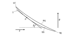
- FIG. 5 is a cross-sectional view taken along the line II in FIG. 4, and shows the cross-sectional shape of the wing part AF at a certain span direction position (position in the height direction of the wing part AF), that is, the wing shape.
- arrows Z and ⁇ indicate the axial direction and the circumferential direction, respectively.
- the airfoil is composed of a concave pressure surface PS and a convex suction surface SS extending between the leading edge LE and the trailing edge TE, respectively.
- a line segment connecting the leading edge LE and the trailing edge TE is called a chord.
- the chord length is called the chord length, and the direction along the chord is called the chord direction.
- the terms “positive pressure surface” and “negative pressure surface” originally represent the curved surface that constitutes the surface of the wing, but in this specification, the term “curve” constitutes the curve that constitutes the profile of the airfoil. Used.
- the airfoil is curved, but this curvature can be grasped as a change in blade surface angle ( ⁇ ) from the leading edge LE to the trailing edge TE.
- the blade surface angle ( ⁇ ) is an angle formed by a tangent (T) at a certain point (P) on the blade surface and the axial direction (Z), and of these, the blade surface at the leading edge LE
- the face angle is called the inlet blade face angle ( ⁇ in)
- the blade face angle at the trailing edge TE is called the outlet blade face angle ( ⁇ ex).
- the blade surface angle ⁇ is defined on each of the pressure surface PS and the suction surface SS, but in FIG. 5, the blade surface at the point P on the suction surface SS is shown in order to avoid complicated drawing. Only the face angle ⁇ is illustrated.
- the inlet blade surface angle ⁇ in is larger than the outlet blade surface angle ⁇ ex, and the blade surface angle ⁇ gradually decreases from the leading edge LE toward the trailing edge TE.
- the blade surface angle ⁇ of the positive pressure surface PS is once larger than the inlet blade surface angle ⁇ in in the region near the front edge LE, it gradually decreases toward the rear edge TE. This is because the positive pressure surface PS has a locally swollen portion in the region near the front edge LE.
- the blade surface angle change rate is introduced as a parameter for objectively grasping the aspect of the blade surface angle change (that is, the degree of reduction from the leading edge LE to the trailing edge TE).
- the blade surface angle change rate ⁇ represents the amount of decrease from the blade surface angle (inlet blade surface angle ⁇ in) at the leading edge LE of the blade surface angle ⁇ at a certain point on the blade surface.
- This parameter is normalized by the total reduction amount of the blade angle from the edge LE to the trailing edge TE (the angle obtained by subtracting the outlet blade angle ⁇ ex from the inlet blade angle ⁇ in), 0 at the leading edge LE, trailing edge Takes a value of 1 in TE.
- the increase in the blade surface angle change rate from the leading edge LE to the trailing edge TE corresponds to the decrease in the blade surface angle on a one-to-one basis.
- the magnitude of the curvature of () can be considered as a gradual increase in the blade angle change rate. Further, by using the blade surface angle change rate, it is possible to compare the degree of decrease in blade surface angle between different blades.
- Patent Document 1 discloses a compressor blade whose loss has been reduced by adjusting the airfoil curvature.
- the angle between the tangent line at the point on the wing-shaped camber line (center line) and the axial direction is ⁇ ′, and the angles at the leading and trailing edges are ⁇ in ′ and ⁇ ex ′, respectively.
- the point on the camber line where the parameter ( ⁇ ′) defined by (Equation 2) is equal to 0.5 is arranged in a predetermined range in the chord direction.
- ⁇ ′ ( ⁇ in′ ⁇ ′) / ( ⁇ in′ ⁇ ex ′) (Formula 2)
- the inter-blade channel formed between two blades adjacent in the circumferential direction is a diffusion flow whose channel area increases from the inlet side (upstream side) to the outlet side (downstream side) of the blade. It is a road. Therefore, when the flow velocity of the air flowing into the inter-blade flow path is subsonic (Mach number ⁇ 0.8), the flow velocity decreases, that is, decelerates as the flow passage area increases as the flow path area increases from the wing inlet side to the outlet side. Arise.
- the transition position from the laminar flow state to the turbulent flow state of the boundary layer is located as downstream as possible in order to make the laminar flow region as wide as possible.
- the transition position is located relatively upstream on the tip side (tip side in the span direction) especially on the pressure side, and especially on the tip side in the midspan on the suction side.
- the upper boundary layer transitioned from a laminar flow state to a turbulent flow state early (that is, upstream), and the laminar flow region was reduced, resulting in an increase in friction loss of the flow between the blades.
- both the pressure surface and the suction surface have a sudden deceleration in the relatively upstream region, and in this region the boundary layer It was found that this transition occurred.
- the portion where the rapid deceleration occurs is considered to be a portion where the flow passage area of the inter-blade flow passage increases suddenly.
- the gradual decrease in angle corresponds to the gradual decrease in angle
- the flow area of the inter-blade flow path suddenly expands on the downstream side, causing a rapid deceleration of the flow, resulting in a laminar state of the boundary layer
- an object of the present invention is to provide a fan and a compressor blade having a reduced laminar flow area on the blade surface to reduce loss.
- the blade of the present disclosure is applied to a fan or a compressor that is a component of a turbofan engine, and is divided into a subsonic region and a transonic region in the height direction.
- the relative Mach number of the airflow flowing into the blades during rated operation of the turbofan engine is less than 0.8 in the subsonic region, 0.8 or more in the transonic region, and each of the height directions
- the cross section at the position comprises a concave pressure surface and a convex suction surface extending between the front edge and the rear edge, respectively, and in the cross section, a tangent at a point above the pressure surface and the suction surface and the turbofan engine
- the blade surface angle ( ⁇ ) is the angle formed with the axial direction of the blade, the blade surface angle at the leading edge is the inlet blade surface angle ( ⁇ in), and the blade surface angle at the trailing edge is the outlet blade surface angle ( ⁇ ex).
- the parameter ( ⁇ ) is referred to as the blade surface angle change rate, and the line segment connecting the leading edge and the trailing edge is measured in the axial direction from the point on the chord, the pressure surface and the suction surface to the leading edge in the axial direction.
- the blade surface angle change rate at the pressure surface of the blade in the subsonic speed region The blade surface angle change rate at a position where the minimum value of -0.90 or more and a cord ratio of 0.39 is 0.43 or less, and the suction surface of the blade in the subsonic region is a blade surface angle at a position of a cord ratio of 0.05.
- the blade surface angle change rate at a position where the change rate is 0.26 or more and the code ratio is 0.36 is 0.58 or less, and on the pressure surface of the blade in the transonic region, the minimum value of the blade surface angle change rate is ⁇ 0.48.
- the blade angle change rate at the cord ratio of 0.35 is 0.12 or less.
- Ri in the negative pressure surface of the blade in the transonic region, wing angle rate of change in position of the code ratio 0.10 0.29 or higher, and the blade surface angle rate of change in position of the code ratio 0.43 is 0.47 or less.
- ⁇ ( ⁇ in ⁇ ) / ( ⁇ in ⁇ ex) (Formula 1)
- the laminar flow region is expanded and the friction loss is reduced by delaying the transition from the laminar flow state to the turbulent flow state of the boundary layer on the blade surface (that is, the transition position is located on the downstream side). An excellent effect can be obtained.
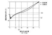
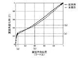
- FIG. 1 It is a schematic explanatory drawing which shows the cross-sectional shape (blade shape) in the certain span direction position of the fan rotor blade of embodiment of this indication compared with the airfoil of the fan rotor blade of a prior art example. It is a figure which shows the chord direction distribution of the blade surface angle change rate of the pressure side in the subsonic region of the fan rotor blade of embodiment of this indication compared with the fan rotor blade of a prior art example. It is a figure which shows the chord direction distribution of the blade surface angle change rate of the suction side in the subsonic region of the fan rotor blade of embodiment of this indication compared with the fan rotor blade of a prior art example.
- FIG. 5 is a cross-sectional view taken along the line II in FIG. 4 and shows a cross-sectional shape (wing shape) of the fan rotor blade.
- chord ratio (x / c) is a dimensionless value obtained by dividing the distance (x) measured in the axial direction from the leading edge by the axial length (c) of the chord.
- the airfoil is changed from the conventional fan blade in accordance with the following policy.
- (1) In order to suppress deceleration in the region of the pressure surface cord ratio of about 0.05, the peak of the blade surface angle change rate that appears in this region is kept small. In other words, the absolute value of the minimum value in this region where the blade surface angle change rate is negative is kept small.
- (2) In the region near the suction side cord ratio of about 0.15, the change in the blade angle is kept small in order to suppress deceleration. Therefore, the change in blade angle is increased in the region near the cord ratio of about 0.05 upstream from this.
- FIG. 1 shows a sectional shape (airfoil shape) of the fan rotor blade of the embodiment of the present disclosure thus obtained in a certain span direction position as compared with the airfoil of the conventional fan rotor blade.
- the chord direction distribution of the blade surface angle change rate of the fan blade according to the embodiment of the present disclosure is shown in FIGS. 2A to 3B in comparison with the blade shape of the conventional fan blade.
- 2A shows the distribution of the pressure surface in the subsonic region
- FIG. 2B shows the distribution of the suction surface in the subsonic region
- FIG. 3A shows the distribution of the pressure surface in the transonic region
- FIG. 3B shows the negative surface in the transonic region.
- the distribution of the pressure surface is shown respectively.
- the vertical axis represents the blade surface angle change rate
- the horizontal axis represents the chord direction position.
- the chord direction position is represented using a chord ratio. Yes.
- the subsonic region and the transonic region are the span direction in which the relative Mach number of the air flow flowing into the blades is less than 0.8 and 0.8 or more, respectively, at the rated operation of the turbofan engine in which the fan blades are incorporated. Point to the area.
- the subsonic region is the region on the inner diameter side where the circumferential velocity component added to the flow by rotation is small, and the transonic region is the outer diameter side where the circumferential velocity component added to the flow by rotation is large. It becomes an area.
- the flow deceleration around the blade is appropriately controlled through the adjustment of the change mode of the blade surface angle change rate as compared with the fan blade of the conventional example.
- the transition position of the boundary layer formed on the blade surface from the laminar flow state to the turbulent flow state moves further downstream.
- the transition position (code ratio) of the fan blade of the conventional example is shown in parentheses following the transition position (code ratio) of the fan blade of the embodiment of the present disclosure.
- the blade surface angle change rate at the transition position of the fan rotor blade of the embodiment of the present disclosure is as follows. ⁇ Pressure surface in subsonic region: 0.43 ⁇ Suction surface in subsonic region: 0.58 ⁇ Pressure surface in the transonic region: 0.12 -Transonic region suction surface: 0.47
- the laminar flow region on the blade surface can be made larger than that of the fan rotor blade of the embodiment of the present disclosure. It can be expanded. This condition is specifically as follows (see (b) in each graph of FIGS. 2A to 3B). -On the pressure surface in the subsonic speed region, the blade angle change rate at a cord ratio of 0.39 should be 0.43 or less. -On the suction surface in the subsonic speed range, the blade surface angle change rate at a cord ratio of 0.36 should be 0.58 or less.
- the blade angle change rate at a cord ratio of 0.35 should be 0.12 or less.
- the blade angle change rate at the code ratio of 0.43 should be 0.47 or less.
- blade shape change policy (2) by making the blade surface angle change rate in the region near the leading edge of the suction surface the same or larger than that of the fan blade of the embodiment of the present disclosure, It is considered that the rapid increase in the blade angle change rate in the downstream region can be suppressed and the rapid deceleration can be prevented.
- This condition is specifically as follows (see (a) in each graph of FIGS. 2B and 3B).
- ⁇ The blade angle change rate at a code ratio of 0.05 in the subsonic speed region is 0.26 or more.
- the blade angle change rate at a transonic region code ratio of 0.10 is 0.29 or more.
- the fan rotor blade of the embodiment of the present disclosure shall satisfy the following conditions.
- ⁇ At the pressure surface in the subsonic region, the minimum value of the blade surface angle change rate is -0.90 or more, and the blade surface angle change rate at a position where the code ratio is 0.39 is 0.43 or less ⁇
- the code ratio is 0.05
- the blade surface angle change rate at the position of 0.26 or more, and the blade surface angle change rate of the code ratio of 0.36 is 0.58 or less.
- the minimum value of the blade surface angle change rate is -0.48 or more,
- the blade surface angle change rate at a cord ratio of 0.35 is 0.12 or less.
- the blade surface angle change rate at a chord ratio of 0.10 is 0.29 or more and the blade surface is at a code ratio of 0.43 at a transonic region suction surface.
- Angle change rate is 0.47 or less
- the blade of the present disclosure is applied to a moving blade of a fan that is a constituent element of a turbofan engine.
- the blade of the present disclosure is not limited to a compressor of a gas turbine other than a turbofan engine.
- the present invention can be widely applied to a moving blade and a stationary blade of a fan or a compressor as one device.
Landscapes
- Engineering & Computer Science (AREA)
- Mechanical Engineering (AREA)
- General Engineering & Computer Science (AREA)
- Physics & Mathematics (AREA)
- Fluid Mechanics (AREA)
- Chemical & Material Sciences (AREA)
- Combustion & Propulsion (AREA)
- Structures Of Non-Positive Displacement Pumps (AREA)
Abstract
Description
翼面角変化率(δ)は、(式1)により定義される。
δ=(βin-β)/(βin-βex) (式1)
δ’=(βin’-β’)/(βin’-βex’) (式2)
δ=(βin-β)/(βin-βex) (式1)
(1)正圧面のコード比約0.05の領域における減速を抑えるため、この領域に出現する翼面角変化率のピークを小さく抑える。換言すれば、翼面角変化率が負となるこの領域における最小値の絶対値を小さく抑える。
(2)負圧面のコード比約0.15近傍の領域においては、減速を抑えるため、翼面角の変化を小さく抑える。そのために、これよりも上流のコード比約0.05近傍の領域において、翼面角の変化を大きくする。
・亜音速領域の負圧面における遷移位置:0.36(0.17)
・遷音速領域の正圧面における遷移位置:0.35(0.03)
・遷音速領域の負圧面における遷移位置:0.43(0.11)
・亜音速領域の正圧面:0.43
・亜音速領域の負圧面:0.58
・遷音速領域の正圧面:0.12
・遷音速領域の負圧面:0.47
・亜音速領域の正圧面においては、コード比0.39の位置における翼面角変化率を0.43以下とする。
・亜音速領域の負圧面においては、コード比0.36の位置における翼面角変化率を0.58以下とする。
・遷音速領域の正圧面においては、コード比0.35の位置における翼面角変化率を0.12以下とする。
・遷音速領域の負圧面においては、コード比0.43の位置における翼面角変化率を0.47以下とする。
・亜音速領域における翼面角変化率の最小値を-0.90以上とする。
・遷音速領域における翼面角変化率の最小値を-0.48以上とする。
・亜音速領域のコード比0.05の位置における翼面角変化率を0.26以上とする。
・遷音速領域のコード比0.10の位置における翼面角変化率を0.29以上とする。
・亜音速領域の正圧面において、翼面角変化率の最小値が-0.90以上、かつ、コード比0.39の位置における翼面角変化率が0.43以下
・亜音速領域の負圧面において、コード比0.05の位置における翼面角変化率が0.26以上、かつ、コード比0.36の位置における翼面角変化率が0.58以下
・遷音速領域の正圧面において、翼面角変化率の最小値が-0.48以上、かつ、コード比0.35の位置における翼面角変化率が0.12以下
・遷音速領域の負圧面において、コード比0.10の位置における翼面角変化率が0.29以上、かつ、コード比0.43の位置における翼面角変化率が0.47以下
AF 翼部
RT 翼根部
PS 正圧面
SS 負圧面
LE 前縁
TE 後縁
β 翼面角
δ 翼面角変化率
Claims (1)
- ターボファンエンジンの構成要素であるファンまたは圧縮機の翼であって、
前記翼は、高さ方向において亜音速領域と遷音速領域とに区分され、前記ターボファンエンジンの定格運転時における前記翼への流入空気流の相対マッハ数が、前記亜音速領域においては0.8未満、前記遷音速領域においては0.8以上であり、
前記翼は、高さ方向の各位置における断面が、前縁と後縁の間をそれぞれ延びる凹状の正圧面と凸状の負圧面から成り、
前記断面において、
前記正圧面及び前記負圧面の上の点における接線と前記ターボファンエンジンの軸方向とのなす角を翼面角(β)、前記前縁における翼面角を入口翼面角(βin)、前記後縁における翼面角を出口翼面角(βex)として、(式1)により定義されるパラメータ(δ)を翼面角変化率と称し、
δ=(βin-β)/(βin-βex) (式1)
前記前縁と前記後縁を結ぶ線分を翼弦、前記正圧面及び前記負圧面の上の点から前記前縁まで軸方向に計った距離(x)を前記翼弦の軸方向長さ(c)により除したパラメータ(x/c)をコード比と称するとき、
前記亜音速領域における前記翼の前記正圧面においては、翼面角変化率の最小値が-0.90以上、かつ、コード比0.39の位置における翼面角変化率が0.43以下であり、
前記亜音速領域における前記翼の前記負圧面においては、コード比0.05の位置における翼面角変化率が0.26以上、かつ、コード比0.36の位置における翼面角変化率が0.58以下であり、
前記遷音速領域における前記翼の前記正圧面においては、翼面角変化率の最小値が-0.48以上、かつ、コード比0.35の位置における翼面角変化率が0.12以下であり、
前記遷音速領域における前記翼の前記負圧面においては、コード比0.10の位置における翼面角変化率が0.29以上、かつ、コード比0.43の位置における翼面角変化率が0.47以下である、翼。
Priority Applications (3)
| Application Number | Priority Date | Filing Date | Title |
|---|---|---|---|
| EP17910748.7A EP3633207A4 (en) | 2017-05-24 | 2017-12-20 | BLADE FOR BLOWER AND COMPRESSOR |
| JP2019519453A JP6734576B2 (ja) | 2017-05-24 | 2017-12-20 | ファン及び圧縮機の翼 |
| US16/690,187 US11125085B2 (en) | 2017-05-24 | 2019-11-21 | Blade of fan or compressor |
Applications Claiming Priority (2)
| Application Number | Priority Date | Filing Date | Title |
|---|---|---|---|
| JP2017-102826 | 2017-05-24 | ||
| JP2017102826 | 2017-05-24 |
Related Child Applications (1)
| Application Number | Title | Priority Date | Filing Date |
|---|---|---|---|
| US16/690,187 Continuation US11125085B2 (en) | 2017-05-24 | 2019-11-21 | Blade of fan or compressor |
Publications (1)
| Publication Number | Publication Date |
|---|---|
| WO2018216255A1 true WO2018216255A1 (ja) | 2018-11-29 |
Family
ID=64396301
Family Applications (1)
| Application Number | Title | Priority Date | Filing Date |
|---|---|---|---|
| PCT/JP2017/045802 Ceased WO2018216255A1 (ja) | 2017-05-24 | 2017-12-20 | ファン及び圧縮機の翼 |
Country Status (4)
| Country | Link |
|---|---|
| US (1) | US11125085B2 (ja) |
| EP (1) | EP3633207A4 (ja) |
| JP (1) | JP6734576B2 (ja) |
| WO (1) | WO2018216255A1 (ja) |
Cited By (2)
| Publication number | Priority date | Publication date | Assignee | Title |
|---|---|---|---|---|
| CN113153815A (zh) * | 2020-11-22 | 2021-07-23 | 西北工业大学 | 一种基于多孔的超声速吸附式压气机叶片 |
| CN120117213A (zh) * | 2025-05-14 | 2025-06-10 | 西北工业大学 | 适应多燃气源的无人机分布式混合动力系统及控制方法 |
Families Citing this family (2)
| Publication number | Priority date | Publication date | Assignee | Title |
|---|---|---|---|---|
| JP6774044B2 (ja) * | 2017-12-20 | 2020-10-21 | 株式会社Ihi | ファン及び圧縮機の静翼 |
| US11873730B1 (en) | 2022-11-28 | 2024-01-16 | Rtx Corporation | Gas turbine engine airfoil with extended laminar flow |
Citations (6)
| Publication number | Priority date | Publication date | Assignee | Title |
|---|---|---|---|---|
| JPH1113692A (ja) * | 1997-06-23 | 1999-01-19 | Hitachi Ltd | 軸流圧縮機翼列 |
| JP2002508043A (ja) * | 1997-06-24 | 2002-03-12 | シーメンス アクチエンゲゼルシヤフト | 圧縮機翼とその用途 |
| JP2006291955A (ja) * | 2005-04-07 | 2006-10-26 | General Electric Co <Ge> | 低ソリディティターボファン |
| US20110206527A1 (en) * | 2010-02-24 | 2011-08-25 | Rolls-Royce Plc | Compressor aerofoil |
| JP2014111941A (ja) * | 2014-03-13 | 2014-06-19 | Hitachi Ltd | 軸流圧縮機 |
| WO2016024461A1 (ja) | 2014-08-12 | 2016-02-18 | 株式会社Ihi | 圧縮機静翼、軸流圧縮機、及びガスタービン |
Family Cites Families (9)
| Publication number | Priority date | Publication date | Assignee | Title |
|---|---|---|---|---|
| US3989406A (en) * | 1974-11-26 | 1976-11-02 | Bolt Beranek And Newman, Inc. | Method of and apparatus for preventing leading edge shocks and shock-related noise in transonic and supersonic rotor blades and the like |
| JP4563653B2 (ja) * | 2003-03-25 | 2010-10-13 | 本田技研工業株式会社 | 高転向・高遷音速翼 |
| US7175393B2 (en) * | 2004-03-31 | 2007-02-13 | Bharat Heavy Electricals Limited | Transonic blade profiles |
| DE502004009528D1 (de) * | 2004-06-02 | 2009-07-09 | Rolls Royce Deutschland | Verdichterschaufel mit verminderter aerodynamischer Schaufelanregung |
| DE102006019946B4 (de) | 2006-04-28 | 2016-12-22 | Honda Motor Co., Ltd. | Flügelprofil für einen Axialströmungskompressor, das die Verluste im Bereich niedriger Reynolds-Zahlen verringern kann |
| DE102006055869A1 (de) * | 2006-11-23 | 2008-05-29 | Rolls-Royce Deutschland Ltd & Co Kg | Schaufelblattdesign für die Lauf- und Leitschaufeln einer Turbomaschine |
| JP4944979B2 (ja) | 2010-06-21 | 2012-06-06 | 本田技研工業株式会社 | 高転向・高遷音速翼 |
| US9790797B2 (en) * | 2011-07-05 | 2017-10-17 | United Technologies Corporation | Subsonic swept fan blade |
| US10184340B2 (en) * | 2013-03-15 | 2019-01-22 | United Technologies Corporation | Geared turbofan engine having a reduced number of fan blades and improved acoustics |
-
2017
- 2017-12-20 EP EP17910748.7A patent/EP3633207A4/en not_active Withdrawn
- 2017-12-20 JP JP2019519453A patent/JP6734576B2/ja active Active
- 2017-12-20 WO PCT/JP2017/045802 patent/WO2018216255A1/ja not_active Ceased
-
2019
- 2019-11-21 US US16/690,187 patent/US11125085B2/en active Active
Patent Citations (6)
| Publication number | Priority date | Publication date | Assignee | Title |
|---|---|---|---|---|
| JPH1113692A (ja) * | 1997-06-23 | 1999-01-19 | Hitachi Ltd | 軸流圧縮機翼列 |
| JP2002508043A (ja) * | 1997-06-24 | 2002-03-12 | シーメンス アクチエンゲゼルシヤフト | 圧縮機翼とその用途 |
| JP2006291955A (ja) * | 2005-04-07 | 2006-10-26 | General Electric Co <Ge> | 低ソリディティターボファン |
| US20110206527A1 (en) * | 2010-02-24 | 2011-08-25 | Rolls-Royce Plc | Compressor aerofoil |
| JP2014111941A (ja) * | 2014-03-13 | 2014-06-19 | Hitachi Ltd | 軸流圧縮機 |
| WO2016024461A1 (ja) | 2014-08-12 | 2016-02-18 | 株式会社Ihi | 圧縮機静翼、軸流圧縮機、及びガスタービン |
Non-Patent Citations (1)
| Title |
|---|
| See also references of EP3633207A4 * |
Cited By (2)
| Publication number | Priority date | Publication date | Assignee | Title |
|---|---|---|---|---|
| CN113153815A (zh) * | 2020-11-22 | 2021-07-23 | 西北工业大学 | 一种基于多孔的超声速吸附式压气机叶片 |
| CN120117213A (zh) * | 2025-05-14 | 2025-06-10 | 西北工业大学 | 适应多燃气源的无人机分布式混合动力系统及控制方法 |
Also Published As
| Publication number | Publication date |
|---|---|
| JP6734576B2 (ja) | 2020-08-05 |
| US20200088039A1 (en) | 2020-03-19 |
| US11125085B2 (en) | 2021-09-21 |
| EP3633207A1 (en) | 2020-04-08 |
| EP3633207A4 (en) | 2021-06-23 |
| JPWO2018216255A1 (ja) | 2019-11-07 |
Similar Documents
| Publication | Publication Date | Title |
|---|---|---|
| EP1798377B1 (en) | Airfoil embodying mixed loading conventions | |
| US7354243B2 (en) | Axial compressor blading | |
| JP6559138B2 (ja) | ターボ機械の構成要素または一群の構成要素、および関連するターボ機械 | |
| US11125085B2 (en) | Blade of fan or compressor | |
| CN106133277B (zh) | 可变导向叶片延伸的可变筋条 | |
| JP2007120494A (ja) | 可変幾何学形状インレットガイドベーン | |
| US8721273B2 (en) | Ring diffuser for an axial turbomachine | |
| US20100129224A1 (en) | Centrifugal compressor | |
| EA028485B1 (ru) | Центробежная машина | |
| JP2009057959A (ja) | 遠心圧縮機とその羽根車およびその運転方法 | |
| JP2022515453A (ja) | 航空エンジンのファンアセンブリのためのモデリング方法 | |
| CN104100305A (zh) | 一种具有正交型可调静叶片的大子午扩张变几何涡轮 | |
| CN104153820A (zh) | 一种具有台阶型球面端壁的大子午扩张变几何涡轮 | |
| US11203945B2 (en) | Stator vane of fan or compressor | |
| US20180030835A1 (en) | Turbine and gas turbine | |
| US10301970B2 (en) | Axial turbine | |
| US10208619B2 (en) | Variable low turbine vane with aft rotation axis | |
| JPH07332007A (ja) | タービン静翼 | |
| JP2000297789A (ja) | 軸流圧縮機 | |
| US6986639B2 (en) | Stator blade for an axial flow compressor | |
| JPH04292502A (ja) | 軸流タービンの静翼 | |
| US10570743B2 (en) | Turbomachine having an annulus enlargment and airfoil | |
| JP2011252431A (ja) | タービンインペラ | |
| JP2007297939A (ja) | タービン翼およびこれを備える蒸気タービン |
Legal Events
| Date | Code | Title | Description |
|---|---|---|---|
| 121 | Ep: the epo has been informed by wipo that ep was designated in this application |
Ref document number: 17910748 Country of ref document: EP Kind code of ref document: A1 |
|
| ENP | Entry into the national phase |
Ref document number: 2019519453 Country of ref document: JP Kind code of ref document: A |
|
| NENP | Non-entry into the national phase |
Ref country code: DE |
|
| WWE | Wipo information: entry into national phase |
Ref document number: 2017910748 Country of ref document: EP |
|
| ENP | Entry into the national phase |
Ref document number: 2017910748 Country of ref document: EP Effective date: 20200102 |