WO2018220774A1 - 運転支援装置、運転支援システムおよび運転支援方法 - Google Patents
運転支援装置、運転支援システムおよび運転支援方法 Download PDFInfo
- Publication number
- WO2018220774A1 WO2018220774A1 PCT/JP2017/020364 JP2017020364W WO2018220774A1 WO 2018220774 A1 WO2018220774 A1 WO 2018220774A1 JP 2017020364 W JP2017020364 W JP 2017020364W WO 2018220774 A1 WO2018220774 A1 WO 2018220774A1
- Authority
- WO
- WIPO (PCT)
- Prior art keywords
- driver
- driving support
- sight
- risk
- vehicle
- Prior art date
- Legal status (The legal status is an assumption and is not a legal conclusion. Google has not performed a legal analysis and makes no representation as to the accuracy of the status listed.)
- Ceased
Links
Images







Classifications
-
- G—PHYSICS
- G08—SIGNALLING
- G08G—TRAFFIC CONTROL SYSTEMS
- G08G1/00—Traffic control systems for road vehicles
- G08G1/16—Anti-collision systems
- G08G1/166—Anti-collision systems for active traffic, e.g. moving vehicles, pedestrians, bikes
-
- G—PHYSICS
- G08—SIGNALLING
- G08G—TRAFFIC CONTROL SYSTEMS
- G08G1/00—Traffic control systems for road vehicles
- G08G1/09—Arrangements for giving variable traffic instructions
- G08G1/0962—Arrangements for giving variable traffic instructions having an indicator mounted inside the vehicle, e.g. giving voice messages
-
- A—HUMAN NECESSITIES
- A61—MEDICAL OR VETERINARY SCIENCE; HYGIENE
- A61B—DIAGNOSIS; SURGERY; IDENTIFICATION
- A61B5/00—Measuring for diagnostic purposes; Identification of persons
- A61B5/16—Devices for psychotechnics; Testing reaction times ; Devices for evaluating the psychological state
- A61B5/163—Devices for psychotechnics; Testing reaction times ; Devices for evaluating the psychological state by tracking eye movement, gaze, or pupil change
-
- A—HUMAN NECESSITIES
- A61—MEDICAL OR VETERINARY SCIENCE; HYGIENE
- A61B—DIAGNOSIS; SURGERY; IDENTIFICATION
- A61B5/00—Measuring for diagnostic purposes; Identification of persons
- A61B5/16—Devices for psychotechnics; Testing reaction times ; Devices for evaluating the psychological state
- A61B5/18—Devices for psychotechnics; Testing reaction times ; Devices for evaluating the psychological state for vehicle drivers or machine operators
-
- B—PERFORMING OPERATIONS; TRANSPORTING
- B60—VEHICLES IN GENERAL
- B60R—VEHICLES, VEHICLE FITTINGS, OR VEHICLE PARTS, NOT OTHERWISE PROVIDED FOR
- B60R1/00—Optical viewing arrangements; Real-time viewing arrangements for drivers or passengers using optical image capturing systems, e.g. cameras or video systems specially adapted for use in or on vehicles
- B60R1/02—Rear-view mirror arrangements
- B60R1/06—Rear-view mirror arrangements mounted on vehicle exterior
-
- B—PERFORMING OPERATIONS; TRANSPORTING
- B60—VEHICLES IN GENERAL
- B60R—VEHICLES, VEHICLE FITTINGS, OR VEHICLE PARTS, NOT OTHERWISE PROVIDED FOR
- B60R21/00—Arrangements or fittings on vehicles for protecting or preventing injuries to occupants or pedestrians in case of accidents or other traffic risks
-
- B—PERFORMING OPERATIONS; TRANSPORTING
- B60—VEHICLES IN GENERAL
- B60R—VEHICLES, VEHICLE FITTINGS, OR VEHICLE PARTS, NOT OTHERWISE PROVIDED FOR
- B60R21/00—Arrangements or fittings on vehicles for protecting or preventing injuries to occupants or pedestrians in case of accidents or other traffic risks
- B60R21/01—Electrical circuits for triggering passive safety arrangements, e.g. airbags, safety belt tighteners, in case of vehicle accidents or impending vehicle accidents
- B60R21/013—Electrical circuits for triggering passive safety arrangements, e.g. airbags, safety belt tighteners, in case of vehicle accidents or impending vehicle accidents including means for detecting collisions, impending collisions or roll-over
-
- G—PHYSICS
- G08—SIGNALLING
- G08G—TRAFFIC CONTROL SYSTEMS
- G08G1/00—Traffic control systems for road vehicles
- G08G1/01—Detecting movement of traffic to be counted or controlled
- G08G1/0104—Measuring and analyzing of parameters relative to traffic conditions
- G08G1/0125—Traffic data processing
-
- G—PHYSICS
- G08—SIGNALLING
- G08G—TRAFFIC CONTROL SYSTEMS
- G08G1/00—Traffic control systems for road vehicles
- G08G1/16—Anti-collision systems
-
- G—PHYSICS
- G08—SIGNALLING
- G08G—TRAFFIC CONTROL SYSTEMS
- G08G1/00—Traffic control systems for road vehicles
- G08G1/16—Anti-collision systems
- G08G1/164—Centralised systems, e.g. external to vehicles
Definitions
- Embodiments described herein relate generally to a driving support device, a driving support system, and a driving support method.
- a driving support device that alerts the driver by notifying the driver of the presence of a dangerous location, an obstacle, or the like (hazard target) is known.
- the name, code, etc., for identifying the dangerous spot etc. are displayed in the line of sight when the driver views the dangerous spot etc., and the voice pattern, such as the name, sign, etc., displayed by the driver's voice, It is determined whether or not they match. Then, if the voice pattern does not match within a predetermined time after displaying the name, code, etc. for identifying the dangerous place etc., a warning is issued to the driver.
- an excessive warning may be issued for the driver's cognitive activity, and driving assistance may be excessively performed.
- driving assistance when driving assistance is excessive, such as issuing a warning to the driver, even though the driver is fully aware of dangerous places, etc., the tendency to depend on the driving assistance of the driver Becomes stronger.
- a driver who is highly dependent on driving assistance has less cognitive activity on the dangerous spot, and for example, the improvement of the prediction ability on the dangerous spot cannot be seen.
- excessive driving assistance may not lead to assistance for the driver's cognitive activities.
- an object is to provide a driving support device, a driving support system, and a driving support method that can realize appropriate driving support for a driver.
- the driving support apparatus includes an environment detection unit, a list generation unit, a line-of-sight detection unit, a risk evaluation unit, and an output control unit.
- the environment detection unit detects an environment around a vehicle driven by the driver.
- the list generation unit generates a hazard list of objects to be hazards based on the detected environment.
- the line-of-sight detection unit detects the driver's line of sight.
- the risk evaluation unit evaluates the driver's driving risk for each target included in the hazard list based on the frequency of the target included in the hazard list within the driver's field of view based on the detected line of sight To do.
- the output control unit outputs driving support information corresponding to an object whose estimated risk is equal to or higher than a threshold value.
- moderate driving assistance can be realized for the driver.
- FIG. 1 is a block diagram illustrating a configuration example of the driving support apparatus according to the first embodiment.
- FIG. 2 is an explanatory diagram illustrating a driver's cognitive structure model.
- FIG. 3 is a block diagram illustrating an example of a hardware configuration of the driving support ECU.
- FIG. 4 is an explanatory diagram illustrating an example of the operation information storage unit.
- FIG. 5 is an explanatory diagram illustrating an example of a hazard list storage unit and a risk table storage unit.
- FIG. 6 is a flowchart illustrating an example of the driving support process.
- FIG. 7 is a flowchart illustrating an example of the situation determination process.
- FIG. 8 is a flowchart illustrating an example of the confirmation operation determination process.
- FIG. 1 is a block diagram illustrating a configuration example of the driving support apparatus according to the first embodiment.
- FIG. 2 is an explanatory diagram illustrating a driver's cognitive structure model.
- FIG. 3 is a block diagram illustrating an example
- FIG. 9 is a flowchart illustrating an example of the hazard list generation process.
- FIG. 10 is a flowchart illustrating an example of the risk evaluation process.
- FIG. 11 is an explanatory diagram for explaining risk calculation.
- FIG. 12 is an explanatory diagram illustrating an example of a hazard map and a risk map.
- FIG. 13 is an explanatory diagram illustrating an example of the confirmation operation.
- FIG. 14 is an explanatory diagram illustrating an example of a driver's forgetting degree with respect to an object.
- FIG. 15 is a flowchart illustrating a modification of the risk evaluation process.
- FIG. 16 is an explanatory diagram for explaining an example of notification outside the vehicle.
- FIG. 17 is a block diagram illustrating a configuration example of the driving support system according to the second embodiment.
- a driving support device a driving support system, and a driving support method according to an embodiment will be described with reference to the drawings.
- configurations having the same functions are denoted by the same reference numerals, and redundant description is omitted.
- the driving support device, the driving support system, and the driving support method described in the following embodiments are merely examples, and do not limit the embodiments.
- the following embodiments may be appropriately combined within a consistent range.
- the “attention message” refers to driving support information for prompting the driver to pay attention to driving operations in a vehicle such as a vehicle (hereinafter referred to as a vehicle).
- the “driver” refers to a target person who supports driving by outputting a warning message, and in each of the following embodiments, the target person is positioned at a driver's seat for driving the vehicle. The case will be described. However, even if the driver is not at the position of the driver's seat, the driver is also included in the driver at a position where the driving operation is possible.
- “virtual output person” refers to a virtual sound source that outputs various types of audio information including alert messages.
- the virtual sound source controls volume (sound pressure) and phase when outputting sound information via a plurality of sound output units (sound output devices such as speakers) arranged around the driver who is driving. Thus, it can be arranged in any direction around the driver. For example, by changing the voice color for each virtual sound source, the driver may be recognized as if there is a person having a predetermined attribute in each direction in which the virtual sound source is arranged.
- a virtual sound source arranged at a position corresponding to the position of the seat around the driver among the virtual output persons is referred to as a “virtual passenger”.
- the “confirmation operation” is an operation performed by the driver for confirmation according to the situation of the vehicle operated by the driver (for example, turning left and right, overtaking, etc.) Movement to grasp the driving environment and situation, such as confirmation of the operation panel and back mirror).
- the “name” refers to a confirmation operation performed by speaking out of the driver's confirmation operations.
- the confirmation operation includes a pointing operation, a line-of-sight movement, and the like in addition to the designation.
- the “name” includes provision of information from a “virtual passenger” by a surrounding monitoring function by a vehicle sensor.
- “repeating” means that virtual passengers simultaneously output information corresponding to the content of the designation (repeated information) after the designation (however, it may not be completely simultaneous, virtual There may be some deviation in the timing of audio output between passengers).
- “continuous call” means that the virtual passengers sequentially output information corresponding to the content of the name after the name.
- “return” of the driver who responds to the preceding “name” from the virtual passenger, and “repetitive call” to “return” all at once from the “virtual passenger” are included. In the following embodiment, the case of “repeating” will be mainly described, but the same processing is performed when “repeating”.
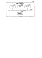
- FIG. 1 is a block diagram illustrating a configuration example of the driving support apparatus according to the first embodiment.
- the driving support device 100 includes a navigation device 111, a vehicle control ECU 112 (ECU: Electronic Control Unit), a gesture detection unit 113, an audio detection unit 114, a gaze detection unit 115, and a surrounding environment detection unit 116.
- the driving support device 100 includes a driving support ECU 120, a sound output unit 131, a display output unit 132, and a communication unit 133.
- the driving assistance device 100 is installed in a vehicle driven by the driver, and provides driving assistance information to the driver by voice output by the voice output unit 131 or display output by the display output unit 132, so that the driver's driving at the time of driving is provided. It is a device that supports cognitive activities.
- FIG. 2 is an explanatory diagram for explaining a driver's cognitive structure model.
- the driver recognizes the surrounding situation as in the cognitive structure model illustrated in FIG. 2, for example, and performs a driving operation.
- the driver recognizes a dangerous area such as a vehicle such as a pedestrian, a preceding vehicle, a succeeding vehicle, an oncoming vehicle or the like in the surrounding environment of the vehicle and the situation (S1). Then, the driver monitors the own vehicle (lanes, speed, etc.) and monitors the surrounding hazard targets (such as between the front, rear, left and right vehicles) (S2).
- a dangerous area such as a vehicle such as a pedestrian, a preceding vehicle, a succeeding vehicle, an oncoming vehicle or the like in the surrounding environment of the vehicle and the situation (S1).
- the driver monitors the own vehicle (lanes, speed, etc.) and monitors the surrounding hazard targets (such as between the front, rear, left and right vehicles) (S2).
- the driver searches for the hazard target by searching for the peripheral visual field within the field of view (S3) (S4), and confirms the change in the situation of the hazard target (S5).
- the driver searches for the hazard target with the central visual field (S6), and supplements the hazard target with the central visual field (S7), thereby updating the recognition of the hazard target (S8).
- the driver does not supplement the hazard target within the central visual field, and the hazard target is forgotten (S9).
- the driver makes a safety judgment based on the recognized hazard object (S10). For example, if the driver does not recall the lane change (S11: NO) depending on the presence or absence of recall of the lane change (change from the driving lane to the overtaking lane) based on the safety judgment (S11: NO) (Accelerator, handle) is performed (S12).
- the driver When recalling a lane change (S11: YES), the driver performs risk prediction for the hazard target (S13), and performs safety check for risk avoidance (S14). Specifically, according to the driving procedure, the safety confirmation of the front hazard, the safety confirmation of the right rear hazard, and the absence of the right blind spot hazard are performed.
- the driver makes a safety confirmation judgment and decides to change lanes (S15).
- the driver who has decided to change the lane presents the blinker (S16), reconfirms the absence of the right blind spot hazard (S17), and then performs a lane change operation (accelerator, steering wheel) (S18).
- the driver confirms safety (S19) and completes the lane change (S20).
- the driving support device 100 For such a driver's cognitive structure model at the time of driving, the driving support device 100 detects the environment around the vehicle that the driver is driving, and the hazard of the target object as a hazard based on the detected environment Generate a list. Then, the driving support device 100 detects the driver's line of sight, and the object included in the hazard list is based on the frequency that the object included in the hazard list is included in the driver's field of view based on the detected line of sight. Assess the risk (low interest) in driving each driver. Then, the driving assistance apparatus 100 outputs driving assistance information corresponding to an object whose estimated risk is equal to or higher than a threshold value by voice output by the voice output unit 131 or display output by the display output unit 132.
- the driving support device 100 evaluates the risk of the target object included in the hazard list detected by the surrounding monitoring sensor based on the frequency included in the driver's field of view, and corresponds to the target object whose risk is equal to or higher than the threshold value.
- driving support information By providing driving support information, excessive driving support can be suppressed, and appropriate driving support for the driver can be realized.
- the driving assistance device 100 is included in the driver's field of view, and the object that the driver recognizes as an object of sufficiently high interest is provided for the object without providing driving assistance information. Do not interfere with the driver's cognitive activities.
- the driving support device 100 provides driving support information for an object that is less frequently included in the driver's field of view and has a low interest, and is insufficiently recognized by the driver, and the driver forgets the object. Suppress it.
- the navigation device 111 detects the current position of the running vehicle using GPS (Global Positioning System), and transmits it to the driving support ECU 120 as position information. In addition, the navigation device 111 detects that the current position of the vehicle has reached a specific position such as an intersection, a branch point, or a junction, and includes a detection result (position detection result) in the position information to drive the ECU 120 for driving assistance. Send to.
- GPS Global Positioning System
- the navigation device 111 determines whether the host vehicle goes straight, turns right, or turns left when it reaches the intersection based on the route search result to the destination and the vehicle status (such as driving history and vehicle speed). Detect whether to do. Similarly, the navigation device 111 detects whether to branch to the left side or to the right side when reaching the branch point based on the route search result to the destination. Furthermore, the navigation device 111 detects whether to join from the right side or from the left side when reaching the joining point based on the route search result to the destination. The navigation device 111 includes these detection results (track detection results) in the position information and transmits them to the driving support ECU 120.
- the vehicle control ECU 112 includes driving operation information (for example, a steering angle of an steering wheel, an opening degree of an accelerator pedal, a depression amount of a brake pedal, etc.) indicating a driving operation performed by the driver on the vehicle, and a vehicle indicating a vehicle state. Information (for example, vehicle speed) is acquired.
- the vehicle control ECU 112 transmits the acquired driving operation information and vehicle information to the driving support ECU 120.
- the gesture detection unit 113 detects a driver's gesture based on an in-vehicle image taken by an in-vehicle camera (not shown). Further, when detecting that the driver has performed the pointing operation, the gesture detection unit 113 determines the pointing direction and transmits the pointing direction information to the driving support ECU 120.
- the voice detection unit 114 detects the name of the driver based on the in-vehicle voice collected by the in-vehicle microphone (not shown) and transmits the name information to the driving support ECU 120.
- the line-of-sight detection unit 115 detects the driver's line-of-sight direction based on the driver's face image captured by an in-vehicle camera (not shown) and transmits the line-of-sight direction information to the driving support ECU 120.
- the surrounding environment detection unit 116 detects obstacles such as pedestrians and other vehicles around the vehicle driven by the driver based on detection information obtained by an in-vehicle sensor (not shown) or an in-vehicle camera (not shown), for example. Then, the surrounding environment information is transmitted to the driving support ECU 120. Specifically, the surrounding environment detection unit 116 includes the identification information that identifies the detected obstacle (for example, a pedestrian, a vehicle, etc.), the position information and speed information of the obstacle with respect to the vehicle driven by the driver, and the like. Information is transmitted to the driving support ECU 120. That is, the surrounding environment detection unit 116 is an example of an environment detection unit. In the example of FIG.
- the detection result is directly transmitted to the driving support ECU 120. May be input to the navigation device 111 or the vehicle control ECU 112. In this case, the navigation device 111 or the vehicle control ECU 112 analyzes the detection result and transmits the surrounding environment information to the driving support ECU 120.
- the surrounding environment information may be acquired via road-to-vehicle communication or vehicle-to-vehicle communication and transmitted to the driving support ECU 120.
- the surrounding environment detection unit 116 functions as a communication unit.
- the driving support ECU 120 performs control for outputting a warning message by voice or display.
- the driving support ECU 120 stores programs for realizing various functions.
- the driving support ECU 120 functions as a situation determination unit 121, an information identification unit 122, an operation determination unit 123, a hazard list generation unit 124, a risk evaluation unit 125, and an output control unit 126 by executing this program.
- the driving support ECU 120 includes an operation information storage unit 127 that stores various information such as operation information, a hazard list, and a risk table, a hazard list storage unit 128, and a risk table storage unit 129.
- FIG. 3 is a block diagram illustrating an example of a hardware configuration of the driving support ECU 120.
- the driving support ECU 120 includes a CPU 201 (CPU: Central Processing Unit), a ROM 202 (ROM: Read Only Memory), a RAM 203 (RAM: Random Access Memory), and a connection device 204.
- each part of ECU120 for driving assistance is mutually connected via the bus
- the CPU 201 is a computer that executes various programs stored in the ROM 202.
- the ROM 202 is a non-volatile memory, and stores various programs executed by the CPU 201 and information (operation information, hazard list, risk table, etc.) used when executing the various programs.
- the RAM 203 is a volatile memory, and provides a work area that is expanded when various programs stored in the ROM 202 are executed by the CPU 201.
- the connection device 204 connects the driving support ECU 120 and an external device, and transmits / receives various information to / from the external device.
- the external device include a navigation device 111, a vehicle control ECU 112, a gesture detection unit 113, a voice detection unit 114, a gaze detection unit 115, a surrounding environment detection unit 116, a voice output unit 131, a display output unit 132, and a communication unit 133. There is.
- the situation determination unit 121 determines the current vehicle situation to the vehicle driver based on the positional information received from the navigation device 111 and the operation information stored in the risk evaluation unit 125. It is determined whether or not a warning message is to be output. When it is determined that the situation determination unit 121 is in a situation where a warning message should be output to the driver of the vehicle, the situation determination unit 121 notifies the information specifying unit 122 of information related to the current vehicle situation. The situation determination unit 121 may further determine the current vehicle situation in accordance with the surrounding environment information received from the surrounding environment detection unit 116.
- the information specifying unit 122 When the information specifying unit 122 acquires information on the current vehicle situation from the situation determining unit 121, the information specifying unit 122 refers to the operation information in the operation information storage unit 127 and is used when outputting a voice alert message to the driver. Information is specified and notified to the output control unit 126. That is, the information specifying unit 122 is an example of a message specifying unit.
- the information specifying unit 122 acquires a warning message and its ID based on information on the current vehicle status. Further, the information specifying unit 122 specifies a direction to be confirmed by the driver based on the acquired alert message, and specifies a virtual output person defined in association with the specified direction. Moreover, the information specific
- the information specifying unit 122 acquires information on the current vehicle situation from the situation determining unit 121, the information specifying unit 122 refers to the operation information of the risk evaluation unit 125, and is used when determining whether the driver's confirmation operation is appropriate. Is identified and notified to the operation determination unit 123.
- the information specifying unit 122 acquires a warning message and its ID based on information on the current vehicle status. In addition, the information specifying unit 122 specifies the order, the pointing direction, the name content, and the line-of-sight direction defined in association with the acquired alert message. And the information specific
- movement
- the operation determining unit 123 When the operation determining unit 123 acquires information used when determining whether the driver's confirmation operation is appropriate from the information specifying unit 122, the operation determining unit 123 receives the pointing direction information from the gesture detecting unit 113, and receives the name information from the voice detecting unit 114. And gaze direction information is received from the gaze detection unit 115.
- the operation determination unit 123 determines whether the driver's confirmation operation is appropriate. At least one of the received pointing direction information, name information, and line-of-sight direction information is acquired by the operation determination unit 123. It is determined whether it corresponds to the information to be used. The operation determination unit 123 determines that the driver of the vehicle has performed an appropriate confirmation operation when it is determined to be applicable.
- the operation determination unit 123 sets in advance a determination result message according to the determination result and a virtual output person of the determination result message based on the determination result of whether or not the driver of the vehicle has performed an appropriate confirmation operation. Is obtained from the set information and the like. Next, the operation determination unit 123 notifies the output control unit 126 of the acquired determination result message and the virtual output person.
- the hazard list generation unit 124 generates a hazard list of objects to be hazards around the vehicle based on the surrounding environment information detected by the surrounding environment detection unit 116. Specifically, the hazard list generation unit 124 sets the obstacle detected by the surrounding environment detection unit 116 as a hazard, assigns a target ID for identifying the target, and includes it in the surrounding environment information A hazard list in which information (identification information, position information, speed information, etc.) for each target object is listed is stored in the hazard list storage unit 128.
- the risk evaluation unit 125 refers to the hazard list in the hazard list storage unit 128, and based on the line-of-sight direction information detected by the line-of-sight detection unit 115, the risk associated with the driving of the driver for each object included in the hazard list To evaluate. Next, the risk evaluation unit 125 outputs the risk evaluation result for each object included in the hazard list to the output control unit 126.
- the risk evaluation unit 125 obtains the frequency included in the driver's field of view indicated by the line-of-sight direction information for each object included in the hazard list. Then, the risk evaluation unit 125 calculates a degree of forgetting that indicates the degree of forgetting of the driver for the object according to the obtained frequency. For example, the risk evaluation unit 125 calculates a higher forgetting degree for an object that is less frequently included in the driver's field of view.
- the risk evaluation unit 125 obtains hazard information that objectively indicates the degree of danger of the object with respect to the vehicle, based on the position information and speed information for each object included in the hazard list.
- the hazard information includes, for example, TTC (Time-To-Collision) that is a collision time to the vehicle for each object.
- TTC is calculated by dividing the distance between the vehicle and the object by the speed difference (relative speed) based on the position information and speed information for each object.
- the risk evaluation unit 125 multiplies hazard information such as TTC by the degree of forgetting for each target object included in the hazard list, thereby evaluating the risk value (hereinafter referred to as risk value) for the driver's driving for each target object. Called). For example, an object having a higher degree of forgetting and a risk has a higher risk value.
- the risk evaluation unit 125 outputs the risk value for each object included in the hazard list to the output control unit 126.
- the output control unit 126 acquires the alert message and its ID, virtual output person, timing, and order notified from the information specifying unit 122.
- the output control unit 126 outputs the acquired alert message via the audio output unit 131 at the acquired timing.
- the output control unit 126 notifies the alert message regarding an object whose risk value is equal to or higher than a preset threshold value based on the risk value for each object included in the hazard list notified from the risk evaluation unit 125. Is output through the audio output unit 131.
- the output control unit 126 refers to the hazard list storage unit 128 to acquire position information of an object whose risk value is equal to or higher than a preset threshold value, and alerts based on the acquired position information.
- the alert message in which the direction to be confirmed in the message matches the position of the object is specified.
- the output control unit 126 outputs the specified alert message via the audio output unit 131 as an alert message relating to the object.
- the driving assistance device 100 can provide a warning message to the driver for an object that is included in the driver's field of view and is not sufficiently recognized by the driver.
- the operation information storage unit 127 is a data table, for example, and stores operation information for each piece of identification information such as an ID.
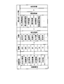
- FIG. 4 is an explanatory diagram illustrating an example of the operation information storage unit 127.
- the motion information storage unit 127 includes “position”, “situation”, “ID”, “attention message”, “direction to be confirmed”, and “virtual output person” as the items of motion information. , “Timing”, “order”, “pointing direction”, “name content”, and “gaze direction”.
- “Position” defines a position where a warning message should be output to the driver.
- the example of FIG. 4 indicates that a warning message is output by voice when the vehicle reaches any of an intersection, a branch point, and a junction.
- “Situation” defines the situation when the vehicle reaches any of an intersection, a junction, or a junction. This is because the direction to be confirmed by the driver differs depending on the situation. For example, when the situation when the intersection is reached is “straight ahead”, the driving support apparatus 100 causes the driver to check the left side and the right side, and the situation when the intersection is reached is “right turn”. If there is, make the driver check the right front and the right turn. In addition, when the situation when the intersection is reached is “left turn”, the driving support device 100 causes the driver to check the left turn destination and the left rear.
- ID stores an identifier for identifying each “attention message” output as a voice in response to “position” and “situation”.
- a virtual output person arranged at a position corresponding to a direction to be confirmed by the driver is defined by outputting a warning message.
- “virtual output person” defines a virtual output person arranged at a position in front of the vehicle.
- the direction to be confirmed “left side”
- the “virtual output person” is defined as a virtual passenger arranged at the position of the passenger seat.
- the direction to be confirmed “right side”
- the “virtual output person” defines a virtual output person arranged at a position on the right side outside the vehicle.
- Timing defines the timing for outputting the alert message
- Order defines the sequence for outputting the alert message
- the alert message “Intersection attention. Pause, confirmation.” Is output as a voice (L / V + 10) seconds before reaching the intersection.
- the alert message “Check right” is output as a voice (L / V + 5) seconds before reaching the intersection.
- the “warning confirmation message for the left confirmation is output by voice (L / V) seconds before the intersection is reached. That is, in the case of the operation information stored in the operation information storage unit 127, the timing of the audio output of the alert message is Each alert message is output as a voice at a predetermined interval, in this case every 5 seconds, depending on the situation. It may be scaled.
- the “pointing direction” stores the direction of the pointing operation that the driver should perform in response to the voice output of the alert message.
- name content the name content to be given by the driver in response to the voice output of the alert message is stored.
- line-of-sight direction stores the line-of-sight direction that the driver should turn in response to the voice output of the alert message.
- the hazard list storage unit 128 is a data table, for example, and stores the hazard list generated by the hazard list generation unit 124.
- the risk table storage unit 129 is, for example, a data table, and stores information related to risk evaluation for each target object included in the hazard list (for example, confirmation frequency, forgetting degree, risk value, flag information, etc.).
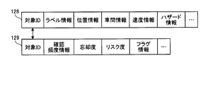
- FIG. 5 is an explanatory diagram for explaining an example of the hazard list storage unit 128 and the risk table storage unit 129. As shown in FIG. 5, in the hazard list storage unit 128 and the risk table storage unit 129, information about the same target object is associated with the target ID.
- the hazard list storage unit 128 stores, for each target ID, label information, position information, inter-vehicle information, speed information, and hazard information of the target object.
- the label information is information that is labeled based on the identification contents of the object (for example, pedestrians, vehicles, etc.), the positional relationship (front and rear), and the relative speed. For example, label information such as “preceding vehicle” is given to vehicles traveling in the same direction ahead, and “following vehicle” is given to vehicles traveling in the same direction behind.
- the position information, the inter-vehicle information, and the speed information are the position of the driver with respect to the vehicle, the inter-vehicle distance, the relative speed, and the like based on the position information and the speed information of the object detected by the surrounding environment detection unit 116.
- Hazard information is TTC etc. concerning the target object calculated based on position information, distance between vehicles, and relative speed.
- the risk table storage unit 129 stores the confirmation frequency information, forgetting degree, risk value, and flag information of each object for each object ID.
- the confirmation frequency information is information indicating the frequency with which the object is captured within the driver's field of view, and is, for example, the time (time) when the object is confirmed to be within the field of view.
- the degree of forgetting is a value calculated by the risk evaluation unit 125 and indicating the degree of forgetting of the driver with respect to the object.
- the risk value is an evaluation value of a risk related to driving of the driver of the target object calculated by the risk evaluation unit 125.
- the flag information is a flag given to the object.
- the flag information includes a risk prediction flag indicating that the driver is predicting (recognizing) a risk for the object by performing a driving operation (accelerator reduction or the like) on the object.
- the audio output unit 131 is an audio output device such as a speaker that performs audio output of information under the control of the output control unit 126.
- the audio output unit 131 outputs the audio information (attention message, determination result message, etc.) transmitted from the output control unit 126 as audio.
- the display output unit 132 is a display or a display lamp that performs display output of information under the control of the output control unit 126.
- the display output unit 132 may be a projection device that projects on an LCD (Liquid Crystal Display) provided on a dashboard or the like, a windshield, or the like.
- the display output unit 132 may include an indicator lamp 132a (LED: Light Emitting Diode, see FIG. 16) provided on a side mirror or the like outside the vehicle in order to perform display output outside the vehicle.
- LED Light Emitting Diode
- the communication unit 133 is a communication device that communicates with an external device by wireless communication under the control of the driving support ECU 120. Specifically, the communication unit 133 performs road-to-vehicle communication, vehicle-to-vehicle communication, communication with the server device 501 (see FIG. 17) via a wireless LAN (Local Area Network), and the like.
- a wireless LAN Local Area Network
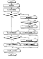
- FIG. 6 is a flowchart illustrating an example of the driving support process.
- the situation determination unit 121 executes a situation determination process (S21).
- FIG. 7 is a flowchart illustrating an example of the situation determination process. As shown in FIG. 7, when the situation determination process is started, the situation determination unit 121 receives the current position information of the vehicle from the navigation device 111 (S30).
- the situation determination unit 121 extracts a position detection result and a course detection result included in the received position information.
- the position detection results include any of intersections, branch points, and junctions.
- the route detection results include straight, right turn, left turn, branch to the right, branch to the left, branch to the left, merge from the right, and merge from the left. Either is included.
- the situation determination unit 121 determines whether the current vehicle situation corresponds to the situation defined in the operation information of the operation information storage unit 127 based on the position detection result and the course detection result (S31). ).
- the situation determination unit 121 If it is determined that the situation defined in the operation information is not applicable (S31: NO), the situation determination unit 121 returns the process to S30. On the other hand, when it is determined that the situation defined in the motion information is applicable (S31: YES), the information specifying unit 122 acquires the ID corresponding to the situation determined by the situation determination unit 121 from the motion information of the motion information storage unit 127. (S32).
- the information specifying unit 122 acquires a warning message corresponding to the acquired ID (S33). For example, when the acquired IDs are “1”, “2”, “3”, the information specifying unit 122 displays “intersection, attention, pause, confirmation”, “left, confirmation” as the corresponding alert message. ",” Right, confirmation. "Is acquired (see FIG. 4).
- the information specifying unit 122 refers to the operation information in the operation information storage unit 127, specifies the direction to be confirmed by the driver based on the acquired alert message, and the virtual output defined in association with the specified direction. Identify the person. Further, the information specifying unit 122 refers to the operation information, and specifies the timing and order specified in association with the acquired alert message (S34).
- the information specifying unit 122 sets “forward” as the direction to be confirmed by the driver.
- the information specifying unit 122 notifies the output control unit 126 of the acquired ID and alert message and the specified virtual output person, timing, and order as information used when outputting the alert message by voice ( S35).
- the information specifying unit 122 refers to the operation information, and is defined in association with the acquired alert message, the order, the pointing direction of the driver, the name content, the line of sight A direction is specified (S36).
- the information specifying unit 122 uses the acquired ID, the specified order, the pointing direction, the name content, and the line-of-sight direction as information used when determining the suitability of the driver's confirmation operation. Notification is made (S37). Thereafter, the information specifying unit 122 returns the process.
- the information specifying unit 122 executes a confirmation operation determination process (S22).
- FIG. 8 is a flowchart illustrating an example of the confirmation operation determination process. As shown in FIG. 8, when the confirmation motion determination process is started, the motion determination unit 123 receives the pointing direction information from the gesture detection unit 113 (S40).
- the operation determination unit 123 determines whether or not the driver's gesture is appropriate (S42). Specifically, the operation determination unit 123 determines whether or not the pointing direction information acquired in S40 matches the “pointing direction” read in S41. If it is determined that they match (S42: YES), the operation determination unit 123 advances the process to S49.
- the motion determination unit 123 determines that the driver's gesture (pointing motion) is not appropriate, and advances the processing to S43.
- the operation determination unit 123 receives the name information from the voice detection unit 114.
- the operation determination unit 123 determines whether or not the driver's name is appropriate (S45). Specifically, the operation determination unit 123 determines whether or not the name information received in S43 matches the “name content” read in S44. When it is determined that they match (S45: YES), the operation determination unit 123 determines that the name of the driver is appropriate, and advances the process to S49.
- the operation determination unit 123 determines that the name of the driver is not appropriate, and proceeds to S46.
- the motion determination unit 123 receives the gaze direction information from the gaze detection unit 115.
- the operation determination unit 123 determines whether or not the driver's line-of-sight direction is appropriate (S48). Specifically, the operation determination unit 123 determines whether or not the line-of-sight direction information received in S46 matches the “line-of-sight direction” read in S47. When it determines with matching (S48: YES), the operation
- the motion determination unit 123 determines that the driver's line-of-sight direction is not appropriate, and proceeds to S52.
- the operation determination unit 123 determines that an appropriate confirmation operation has been performed by the driver.
- the operation determination unit 123 reads out a determination result message and a virtual output person corresponding to a case where an appropriate confirmation operation has been performed from the setting information set in advance, and notifies the output control unit 126 (S50).
- the determination result message includes a sound such as “good” and “confirmation” giving up an appropriate confirmation operation, and a clear sound.
- the virtual output person may be “all virtual passengers”. Further, it may be “repeated” by the virtual passenger again (“continuous call”) in accordance with the timing of the last call “Yoshi” so as not to disturb the driver's continuous call.
- the output control unit 126 outputs the determination result message notified from the operation determination unit 123 via the audio output unit 131 (S51). Accordingly, it is possible to notify the driver that an appropriate confirmation operation is being performed with a sound such as “good” or “confirmation” or a clear sound. Thereafter, the output control unit 126 returns the processing.
- the operation determination unit 123 determines that an appropriate confirmation operation has not been performed by the driver.
- the operation determination unit 123 reads out a determination result message and a virtual output person corresponding to a case where an appropriate confirmation operation has not been performed from preset setting information and notifies the output control unit 126 (S53).
- the determination result message includes a voice such as “not confirmed” indicating that an appropriate confirmation operation has not been performed, a beep sound, and the like.
- the virtual output person may be “all virtual passengers”.
- the output control unit 126 outputs the determination result message notified from the operation determination unit 123 via the audio output unit 131 (S54). Accordingly, it is possible to notify the driver that the confirmation operation is not properly performed with a sound such as “not confirmed” or a beep sound. Thereafter, the output control unit 126 returns the processing.
- the hazard list generation unit 124 updates (generates) a hazard list of an object to be a hazard around the vehicle based on the surrounding environment information detected by the surrounding environment detection unit 116. (S23).
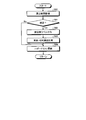
- FIG. 9 is a flowchart illustrating an example of the hazard list generation process.
- the hazard list generation unit 124 monitors vehicles around the vehicle driven by the driver based on the surrounding environment information (S60). Next, the hazard list generation unit 124 determines whether or not changes in surrounding vehicles (for example, detection of a new vehicle, position of a vehicle that has already been detected, change in speed, etc.) have been supplemented as a result of monitoring. (S61).
- the hazard list generation unit 124 labels “preceding vehicle”, “following vehicle”, etc. based on the surrounding environment information for the vehicle (peripheral vehicle) supplemented with the change. (S62), and the inter-vehicle / relative speed is measured (S63).
- the hazard list generation unit 124 applies the hazard list storage unit 128 applied to the vehicle (target object) supplemented with changes based on the label given in S62 and the inter-vehicle distance and relative speed measured in S63.
- the hazard list is updated (S64).
- generation part 124 skips S62 and S63 and advances a process to S64. In this case, since there is no vehicle in which the change is supplemented, the contents of the hazard list in the hazard list storage unit 128 are not updated and remain as they are. After S64, the hazard list generator 124 returns the process.
- the risk evaluation unit 125 refers to the hazard list in the hazard list storage unit 128, and targets included in the hazard list based on the line-of-sight direction information detected by the line-of-sight detection unit 115.
- the risk of driving for each driver is evaluated (S24).
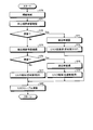
- FIG. 10 is a flowchart illustrating an example of the risk evaluation process.
- the risk evaluation unit 125 detects the driver's line of sight based on the line-of-sight direction information from the line-of-sight detection unit 115, and the driver's field of view (center field of view and peripheral field of view). ) Direction is detected (S70). For example, when the driver's line of sight is ahead, the central visual field is “front”, and the peripheral visual fields are “right front”, “left front”, and the like.
- the risk evaluation unit 125 confirms whether or not the line of sight remains for a predetermined period in the central visual field (S71), and determines whether or not there is a stop (S72).
- the risk evaluation unit 125 based on the position information stored in the hazard list storage unit 128, the target in the central visual field from among the objects of the hazard list An object (peripheral car) is confirmed (S73).
- the risk evaluation unit 125 evaluates the risk of the object confirmed to be within the central field of view. Specifically, the risk evaluation unit 125 obtains hazard information such as TTC from the position information and speed information related to the object included in the hazard list of the hazard list storage unit 128. Next, the risk evaluation unit 125 clears the forgetting degree (reset to a value indicating no forgetting) as the object most recently confirmed in the central visual field, and then multiplies the forgetting degree by the hazard information to obtain the risk value. Estimate (S74).
- the risk evaluation unit 125 confirms whether there is a stop that stays for a predetermined period in the peripheral visual field (S75), and determines whether there is a stop (S76).
- the risk evaluation unit 125 evaluates the risk for the object outside the visual field. Specifically, the risk evaluation unit 125 obtains hazard information such as TTC from the position information and speed information related to the object included in the hazard list of the hazard list storage unit 128. Next, the risk evaluation unit 125 reads the previous risk value from the risk table storage unit 129, increases the forgetting degree from the previous time as an object outside the field of view, and then multiplies the forgetting degree by the hazard information to obtain the risk value. Is estimated (S77).
- hazard information such as TTC from the position information and speed information related to the object included in the hazard list of the hazard list storage unit 128.
- the risk evaluation unit 125 When there is a stop in the peripheral visual field (S76: YES), the risk evaluation unit 125, based on the position information stored in the hazard list storage unit 128, the target in the peripheral visual field from among the objects of the hazard list The object (peripheral car) is confirmed (S78).
- the risk evaluation unit 125 evaluates the risk of the object confirmed to be within the peripheral vision. Specifically, the risk evaluation unit 125 obtains hazard information such as TTC from the position information and speed information related to the object included in the hazard list of the hazard list storage unit 128. Next, the risk evaluation unit 125 reads the previous risk value from the risk table storage unit 129, maintains the forgetting degree as the object most recently confirmed in the peripheral visual field (the same value as the previous time), and then sets the forgetting degree. The risk value is estimated by multiplying the hazard information (S79).
- FIG. 11 is an explanatory diagram for explaining risk calculation.
- the forgetting degree corresponding to the confirmation frequency is multiplied by the TTC calculated based on the positional relationship, distance, relative speed, and the like.
- the risk value is calculated by combining them. Therefore, an object included in the hazard list is evaluated with a lower risk as an object having a higher frequency in the driver's central vision or peripheral vision. Conversely, more frequent objects that are outside the driver's field of view are more highly assessed for risk.
- the risk evaluation unit 125 updates the risk table in the risk table storage unit 129 based on the risk value estimated for the object (S80), and returns the process.
- the output control unit 126 has a risk value equal to or higher than a preset threshold value based on the risk value for each object included in the hazard list notified from the risk evaluation unit 125. It is determined whether there is an object (S25).
- the output control unit 126 When there is an object whose risk value is equal to or greater than a preset threshold value (S25: YES), the output control unit 126 outputs a warning message relating to the determined object via the audio output unit 131 and outputs the message. The name is guided to the person (S26). When there is no object whose risk value is equal to or greater than the preset threshold value (S25: NO), the output control unit 126 returns the process.
- the output control unit 126 refers to the hazard list storage unit 128 to acquire position information of an object whose risk value is equal to or higher than a preset threshold value, and alerts based on the acquired position information.
- the alert message in which the “direction to be confirmed” in the message matches the position of the object is specified.
- FIG. 12 is an explanatory diagram illustrating an example of a hazard map and a risk map.
- a hazard map 301 in FIG. 12 illustrates the hazard list in the hazard list storage unit 128 in a map format.
- the risk map 302 illustrates the contents of the risk table storage unit 129 (the objects 311 to 314 for the host vehicle 310) in a map format.
- the risk values of the objects 311 to 314 are evaluated as 311 ⁇ 312 ⁇ 313 ⁇ 314, and the risk value of the object 314 is equal to or higher than the threshold because the degree of forgetting is high.
- the output control unit 126 calls attention in the alert message notified from the information specifying unit 122.
- a message whose “direction to be confirmed” in the message is “right” is specified.
- the output control unit 126 specifies the alert message “right, attention”.
- the output control unit 126 outputs the specified alert message via the audio output unit 131 as an alert message relating to the object.
- the driving assistance apparatus 100 can provide the driver with a warning message relating to an object that is not included in the driver's field of view and is not sufficiently recognized by the driver.
- a warning message such as “right, attention” can be provided to guide the driver to confirm the right side.
- word meaning can be emphasized by emphasizing punctuation marks.
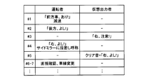
- FIG. 13 is an explanatory diagram for explaining an example of the confirmation operation.
- a warning message such as “right, attention!” Is provided to the driver as “# 3” in FIG. Is done.
- the driver can re-recognize the object 314 having a high degree of forgetting, and can guide name confirmation such as “Right, Good!” In “# 4”.
- the output control unit 126 outputs a determination result message such as a clear sound as in “5” for an appropriate confirmation operation in “# 4”. Thereby, the driving assistance apparatus 100 can notify the driver that an appropriate confirmation operation is being performed.
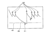
- FIG. 14 is an explanatory diagram for explaining an example of a driver's forgetting degree with respect to an object.
- FIG. 14 shows a graph 400 of the degree of object recognition (the higher the degree of forgetting, the lower the degree of forgetting and the opposite of the degree of forgetting).
- the vertical axis is the degree of recognition and the horizontal axis is the time axis.
- the driving support device 100 provides a warning message to the driver by the notification 411 when the cognitive activity 410 is spaced and the graph 400 falls below the threshold 401 (the forgetting degree exceeds the threshold 401). As a result, the driver can re-recognize the object whose degree of recognition is low.
- the risk assessment process is based not only on the driver's line of sight but also on whether the driver predicts (recognizes) the risk to the object as driving operations (accelerator reduction etc.) are performed. May be.
- FIG. 15 is a flowchart showing a modified example of the risk evaluation process.
- the risk evaluation unit 125 determines whether or not there is a driving operation (accelerator reduction) for a peripheral vehicle within the central visual field based on the driving operation information from the vehicle control ECU 112 (S81).
- the risk prediction flag is stored in the flag information of the surrounding vehicles in the risk table storage unit 129 (S82).
- the risk evaluation unit 125 calculates a risk value in S74, S77, and S79 according to the presence or absence of the risk prediction flag. Specifically, when there is a risk prediction flag, the driver predicts (recognizes) the risk for the object, so the risk value is calculated lower than when there is no risk prediction flag.
- the output control unit 126 may display the presence / absence of the confirmation operation on a display device provided outside the vehicle based on the result of the confirmation operation determination process (S40 to S54).
- FIG. 16 is an explanatory diagram for explaining an example of notification outside the vehicle.
- the output control unit 126 sets the indicator lamp 132a provided on the side mirror to a lighting display (for example, yellow display) indicating alerting (S90) before confirmation.
- the output control unit 126 sets the indicator lamp 132a to a lighting display (for example, blue display) indicating safety confirmation (S91). .
- the output control unit 126 changes the indicator lamp 132a to a lighting display (for example, red display) indicating no confirmation ( S92).
- a lighting display for example, red display
- mutual safety confirmation can be performed between vehicles.
- the risk evaluation unit 125 sets a threshold value for evaluating the risk value according to the operation mode (automatic operation mode, high-speed operation mode, preceding vehicle follow-up mode, manual operation mode, etc.) set by the driver D or the like. May be. For example, immediately after switching from the automatic operation mode to the manual operation mode, there may be a slow cognitive activity accustomed to the automatic operation mode. Therefore, immediately after switching from the automatic operation mode to the manual operation mode, the threshold value may be set low to increase the frequency at which the alert message is output. Further, in the automatic driving mode, the cognitive activity as in the manual driving mode is not necessary, so the threshold value may be set higher and the frequency of outputting the alert message may be lowered.
- the operation mode automated operation mode, high-speed operation mode, preceding vehicle follow-up mode, manual operation mode, etc.
- the configuration of the driving support device 100 alone is illustrated.
- a server device having the same function as the driving support ECU 120 is prepared separately from the driving support device 100 and connected to each other via a communication network.
- the driving support device 100 and the server device that cooperate may implement the above functions.
- FIG. 17 is a block diagram illustrating a configuration example of the driving support system according to the second embodiment.
- driving support devices 100A and 100B and a server device 501 are connected to be communicable with each other via a communication network N such as a wireless LAN.
- the server device 501 is a driving that connects functions such as the situation determination unit 121, the information identification unit 122, the operation determination unit 123, the hazard list generation unit 124, and the risk evaluation unit 125 in the driving support ECU 120 via the communication network N.
- the server device 501 includes a hazard list for each driving support device 100A, 100B,..., A hazard list storage unit 128 for storing a risk table, and a risk table storage unit 129.
- the configuration of such a driving support system 500 has an advantage that the server device 501 can interpolate a part of information for each of the driving support devices 100A, 100B,. For example, in a hazard list between vehicles that are close to each other, an object that is lacking in one hazard list can be interpolated from the contents of the other hazard list.
- the driving support device 100 includes the surrounding environment detection unit 116, the hazard list generation unit 124, the line-of-sight detection unit 115, the risk evaluation unit 125, and the output control unit 126.
- the surrounding environment detection unit 116 detects the environment around the vehicle that the driver drives.
- the hazard list generation unit 124 generates a hazard list of objects to be hazards based on the detected environment.
- the line-of-sight detection unit 115 detects the driver's line of sight.
- the risk evaluation unit 125 determines the risk of driving the driver for each target included in the hazard list based on the frequency that the target included in the hazard list is included in the driver's field of view based on the detected line of sight. evaluate.
- the output control unit 126 outputs driving support information corresponding to an object whose estimated risk is equal to or higher than a threshold value.
- the driving support device 100 can suppress excessive driving support and can realize appropriate driving support for the driver.
- the driving assistance device 100 is frequently included in the driver's field of view, and the driver's cognitive activity on the object without providing driving assistance information for the object that the driver sufficiently recognizes. Do not disturb.
- the driving assistance device 100 provides driving assistance information for an object whose frequency of being included in the driver's field of view is low and the driver's recognition is insufficient, and prevents the driver from forgetting the object. To do.
- the risk evaluation unit 125 calculates a degree of forgetting that indicates the degree of forgetting of the driver with respect to the object based on whether or not the object included in the hazard list is included in the driver's field of view based on the detected line of sight. To do. Then, the risk evaluation unit 125 evaluates the risk based on the calculated degree of forgetting and the collision time to the vehicle for each object included in the hazard list. As described above, the hazard list is obtained by performing the risk evaluation based on the driver's forgetting degree with respect to the object, that is, the degree of recognition of the object and the collision time when the object collides with the vehicle, that is, the objective risk of the object. It is possible to appropriately evaluate the risk of the objects included in.
- the risk evaluation unit 125 resets the value of the forgetting degree of the object when the object is included in the driver's central visual field based on the driver's line of sight. Further, when the object is included in the driver's peripheral vision based on the driver's line of sight, the value of the forgetting degree of the object is maintained. Further, when the object is not included in the central visual field and the peripheral visual field of the driver based on the driver's line of sight, the value of the degree of forgetting of the object is increased. In this way, the risk assessment of each object can be appropriately performed by changing the evaluation of the driver's forgetting degree with respect to the object when the object is not included in either the driver's central vision or peripheral vision. It can be carried out.
- each component of each illustrated apparatus does not necessarily need to be physically configured as illustrated.
- the specific form of distribution / integration of each device is not limited to that shown in the figure, and all or a part thereof may be functionally or physically distributed or arbitrarily distributed in arbitrary units according to various loads or usage conditions. Can be integrated and configured.
- various processing functions performed by the driving support devices 100, 100A, 100B, and the server device 501 are all or any part of them on a CPU (or a microcomputer such as an MPU or MCU (Micro Controller Unit)). You may make it perform.
- various processing functions may be executed in whole or in any part on a program that is analyzed and executed by a CPU (or a microcomputer such as an MPU or MCU) or hardware based on wired logic. Needless to say, it is good.
- various processing functions performed in the server device 501 may be executed by a plurality of computers in cooperation with each other by cloud computing.
- the various processing functions described in the above embodiments can be realized by executing a prepared program on a computer.
- This program may not be stored in a computer memory or the like.
- a program stored in a computer-readable storage medium may be read and executed.
- the computer-readable storage medium corresponds to, for example, a CD-ROM, a DVD disk, a portable recording medium such as a USB (Universal Serial Bus) memory, a semiconductor memory such as a flash memory, and a hard disk drive.
- the program may be stored in a device connected to a public line, the Internet, a LAN, or the like, and the computer may read and execute the program from these.
- Bus 301 Hazard map 310 ... Own vehicle 311 to 314 ... Object 302 ... Risk map 400 ... Graph 401 ... Threshold 410 ... Cognitive activity 411 ... Notification 500 ... Driving support system 501 ... Server device D ... Driving N ... Communication network
Landscapes
- Health & Medical Sciences (AREA)
- Engineering & Computer Science (AREA)
- Life Sciences & Earth Sciences (AREA)
- Physics & Mathematics (AREA)
- General Physics & Mathematics (AREA)
- Pathology (AREA)
- Heart & Thoracic Surgery (AREA)
- Educational Technology (AREA)
- Hospice & Palliative Care (AREA)
- Psychiatry (AREA)
- Psychology (AREA)
- Social Psychology (AREA)
- Child & Adolescent Psychology (AREA)
- Biophysics (AREA)
- Mechanical Engineering (AREA)
- Biomedical Technology (AREA)
- Developmental Disabilities (AREA)
- Medical Informatics (AREA)
- Molecular Biology (AREA)
- Surgery (AREA)
- Animal Behavior & Ethology (AREA)
- General Health & Medical Sciences (AREA)
- Public Health (AREA)
- Veterinary Medicine (AREA)
- Multimedia (AREA)
- Chemical & Material Sciences (AREA)
- Analytical Chemistry (AREA)
- Traffic Control Systems (AREA)
- Measurement Of The Respiration, Hearing Ability, Form, And Blood Characteristics Of Living Organisms (AREA)
Abstract
Description
図1は、第1の実施形態にかかる運転支援装置の構成例を示すブロック図である。
リスク評価処理については、運転者の視線だけでなく、対象物に対する運転操作(アクセル減など)が行われ、対象物に対するリスクを運転者が予測(認知)しているか否かをもとに行ってもよい。
上記の第1の実施形態では運転支援装置100単体の構成を例示したが、運転支援装置100とは別に運転支援用ECU120と同様の機能を有するサーバ装置を用意し、通信ネットワークを介して互いに接続する運転支援装置100とサーバ装置とが協働して上記の機能を実現してもよい。
111…ナビゲーション装置
112…車両制御ECU
113…ジェスチャ検出部
114…音声検出部
115…視線検出部
116…周辺環境検出部
120…運転支援用ECU
121…状況判定部
122…情報特定部
123…動作判定部
124…ハザードリスト生成部
125…リスク評価部
126…出力制御部
127…動作情報格納部
128…ハザードリスト格納部
129…リスクテーブル格納部
131…音声出力部
132…表示出力部
132a…表示灯
133…通信部
201…CPU
202…ROM
203…RAM
204…接続装置
205…バス
301…ハザードマップ
310…自車
311~314…対象物
302…リスクマップ
400…グラフ
401…閾値
410…認知活動
411…報知
500…運転支援システム
501…サーバ装置
D…運転者
N…通信ネットワーク
Claims (21)
- 運転者が運転する乗り物の周囲の環境を検出する環境検出部と、
検出された前記環境に基づいてハザードとする対象物のハザードリストを生成するリスト生成部と、
前記運転者の視線を検出する視線検出部と、
検出された前記視線に基づく前記運転者の視野内に前記ハザードリストに含まれる対象物が含まれる頻度に基いて、前記ハザードリストに含まれる対象物ごとの前記運転者の運転にかかるリスクを評価するリスク評価部と、
評価された前記リスクが閾値以上の対象物に対応する運転支援情報を出力させる出力制御部と、
を有することを特徴とする運転支援装置。 - 前記リスク評価部は、検出された前記視線に基づく前記運転者の視野内に前記ハザードリストに含まれる対象物が含まれるか否かに基いて前記対象物に対する運転者の忘却度合いを示す忘却度を算出し、当該算出した忘却度と、前記ハザードリストに含まれる対象物ごとの前記乗り物までの衝突時間とに基いて前記リスクを評価する、
ことを特徴とする請求項1に記載の運転支援装置。 - 前記リスク評価部は、前記視線に基づく前記運転者の中心視野内に前記対象物が含まれる場合、当該対象物の忘却度の値をリセットし、前記視線に基づく前記運転者の周辺視野内に前記対象物が含まれる場合、当該対象物の忘却度の値を維持し、前記視線に基づく前記運転者の中心視野および周辺視野内に前記対象物が含まれない場合、当該対象物の忘却度の値を増加する、
ことを特徴とする請求項2に記載の運転支援装置。 - 前記運転者が操作する乗り物の状況を判定する状況判定部と、
判定された前記状況に基いて前記運転者に対して注意喚起を行うメッセージを特定するメッセージ特定部と、を更に有し、
前記出力制御部は、特定された前記メッセージの中で、評価された前記リスクが閾値以上の対象物に対応するメッセージを前記運転支援情報として出力させる、
ことを特徴とする請求項1乃至3のいずれか一項に記載の運転支援装置。 - 判定された前記状況に対応する確認動作を運転者が行ったか否かを判定する動作判定部を更に有し、
前記出力制御部は、前記確認動作を行ったと判定した場合、当該確認動作に対応するメッセージを出力させる、
ことを特徴とする請求項4に記載の運転支援装置。 - 前記出力制御部は、前記確認動作の有無を前記乗り物の外側に設けられた表示装置に表示させる、
ことを特徴とする請求項5に記載の運転支援装置。 - 前記出力制御部は、前記乗り物の運転モードに基づく閾値を設定する、
ことを特徴とする請求項1に記載の運転支援装置。 - 運転支援装置と、サーバ装置とが通信ネットワークを介して通信可能に接続される運転支援システムであって、
前記運転支援装置は、
運転者が運転する乗り物の周囲の環境を検出する環境検出部と、
前記運転者の視線を検出する視線検出部と、を有する運転支援装置と、を有し、
前記サーバ装置は、
検出された前記環境に基づいてハザードとする対象物のハザードリストを生成するリスト生成部と、
検出された前記視線に基づく前記運転者の視野内に前記ハザードリストに含まれる対象物が含まれる頻度に基いて、前記ハザードリストに含まれる対象物ごとの前記運転者の運転にかかるリスクを評価するリスク評価部と、
評価された前記リスクが閾値以上の対象物に対応する運転支援情報を前記運転支援装置より出力させる出力制御部と、
を有することを特徴とする運転支援システム。 - 前記リスク評価部は、検出された前記視線に基づく前記運転者の視野内に前記ハザードリストに含まれる対象物が含まれるか否かに基いて前記対象物に対する運転者の忘却度合いを示す忘却度を算出し、当該算出した忘却度と、前記ハザードリストに含まれる対象物ごとの前記乗り物までの衝突時間とに基いて前記リスクを評価する、
ことを特徴とする請求項8に記載の運転支援システム。 - 前記リスク評価部は、前記視線に基づく前記運転者の中心視野内に前記対象物が含まれる場合、当該対象物の忘却度の値をリセットし、前記視線に基づく前記運転者の周辺視野内に前記対象物が含まれる場合、当該対象物の忘却度の値を維持し、前記視線に基づく前記運転者の中心視野および周辺視野内に前記対象物が含まれない場合、当該対象物の忘却度の値を増加する、
ことを特徴とする請求項9に記載の運転支援システム。 - 前記サーバ装置は、
前記運転者が操作する乗り物の状況を判定する状況判定部と、
判定された前記状況に基いて前記運転者に対して注意喚起を行うメッセージを特定するメッセージ特定部と、を更に有し、
前記出力制御部は、特定された前記メッセージの中で、評価された前記リスクが閾値以上の対象物に対応するメッセージを前記運転支援情報として出力させる、
ことを特徴とする請求項8乃至10のいずれか一項に記載の運転支援システム。 - 前記サーバ装置は、
判定された前記状況に対応する確認動作を運転者が行ったか否かを判定する動作判定部を更に有し、
前記出力制御部は、前記確認動作を行ったと判定した場合、当該確認動作に対応するメッセージを出力させる、
ことを特徴とする請求項11に記載の運転支援システム。 - 前記出力制御部は、前記確認動作の有無を前記運転支援装置により前記乗り物の外側に設けられた表示装置に表示させる、
ことを特徴とする請求項12に記載の運転支援システム。 - 前記出力制御部は、前記乗り物の運転モードに基づく閾値を設定する、
ことを特徴とする請求項8に記載の運転支援システム。 - 運転者が運転する乗り物の周囲の環境を検出する環境検出部より検出された前記環境に基づいてハザードとする対象物のハザードリストを生成し、
前記運転者の視線を検出する視線検出部より検出された前記視線に基づく前記運転者の視野内に前記ハザードリストに含まれる対象物が含まれる頻度に基いて、前記ハザードリストに含まれる対象物ごとの前記運転者の運転にかかるリスクを評価し、
評価された前記リスクが閾値以上の対象物に対応する運転支援情報を出力させる
処理をコンピュータが実行することを特徴とする運転支援方法。 - 前記リスクを評価する処理は、検出された前記視線に基づく前記運転者の視野内に前記ハザードリストに含まれる対象物が含まれるか否かに基いて前記対象物に対する運転者の忘却度合いを示す忘却度を算出し、当該算出した忘却度と、前記ハザードリストに含まれる対象物ごとの前記乗り物までの衝突時間とに基いて前記リスクを評価する、
ことを特徴とする請求項15に記載の運転支援方法。 - 前記リスクを評価する処理は、前記視線に基づく前記運転者の中心視野内に前記対象物が含まれる場合、当該対象物の忘却度の値をリセットし、前記視線に基づく前記運転者の周辺視野内に前記対象物が含まれる場合、当該対象物の忘却度の値を維持し、前記視線に基づく前記運転者の中心視野および周辺視野内に前記対象物が含まれない場合、当該対象物の忘却度の値を増加する、
ことを特徴とする請求項16に記載の運転支援方法。 - 前記運転者が操作する乗り物の状況を判定し、
判定された前記状況に基いて前記運転者に対して注意喚起を行うメッセージを特定する処理を更にコンピュータが実行し、
前記出力させる処理は、特定された前記メッセージの中で、評価された前記リスクが閾値以上の対象物に対応するメッセージを前記運転支援情報として出力させる、
ことを特徴とする請求項15乃至17のいずれか一項に記載の運転支援方法。 - 判定された前記状況に対応する確認動作を運転者が行ったか否かを判定する処理を更にコンピュータが実行し、
前記出力させる処理は、前記確認動作を行ったと判定した場合、当該確認動作に対応するメッセージを出力させる、
ことを特徴とする請求項18に記載の運転支援方法。 - 前記出力させる処理は、前記確認動作の有無を前記乗り物の外側に設けられた表示装置に表示させる、
ことを特徴とする請求項19に記載の運転支援方法。 - 前記出力させる処理は、前記乗り物の運転モードに基づく閾値を設定する、
ことを特徴とする請求項15に記載の運転支援方法。
Priority Applications (4)
| Application Number | Priority Date | Filing Date | Title |
|---|---|---|---|
| JP2019521624A JP6860068B2 (ja) | 2017-05-31 | 2017-05-31 | 運転支援装置、運転支援システムおよび運転支援方法 |
| EP17911992.0A EP3633650A4 (en) | 2017-05-31 | 2017-05-31 | DRIVING AID DEVICE, DRIVING AID SYSTEM, AND DRIVING AID METHOD |
| PCT/JP2017/020364 WO2018220774A1 (ja) | 2017-05-31 | 2017-05-31 | 運転支援装置、運転支援システムおよび運転支援方法 |
| US16/694,453 US11276313B2 (en) | 2017-05-31 | 2019-11-25 | Information processing device, drive assist system, and drive assist method |
Applications Claiming Priority (1)
| Application Number | Priority Date | Filing Date | Title |
|---|---|---|---|
| PCT/JP2017/020364 WO2018220774A1 (ja) | 2017-05-31 | 2017-05-31 | 運転支援装置、運転支援システムおよび運転支援方法 |
Related Child Applications (1)
| Application Number | Title | Priority Date | Filing Date |
|---|---|---|---|
| US16/694,453 Continuation US11276313B2 (en) | 2017-05-31 | 2019-11-25 | Information processing device, drive assist system, and drive assist method |
Publications (1)
| Publication Number | Publication Date |
|---|---|
| WO2018220774A1 true WO2018220774A1 (ja) | 2018-12-06 |
Family
ID=64454571
Family Applications (1)
| Application Number | Title | Priority Date | Filing Date |
|---|---|---|---|
| PCT/JP2017/020364 Ceased WO2018220774A1 (ja) | 2017-05-31 | 2017-05-31 | 運転支援装置、運転支援システムおよび運転支援方法 |
Country Status (4)
| Country | Link |
|---|---|
| US (1) | US11276313B2 (ja) |
| EP (1) | EP3633650A4 (ja) |
| JP (1) | JP6860068B2 (ja) |
| WO (1) | WO2018220774A1 (ja) |
Cited By (3)
| Publication number | Priority date | Publication date | Assignee | Title |
|---|---|---|---|---|
| JP2021174054A (ja) * | 2020-04-20 | 2021-11-01 | 株式会社小松製作所 | 作業機械の障害物報知システムおよび作業機械の障害物報知方法 |
| JP2022139599A (ja) * | 2021-03-12 | 2022-09-26 | パイオニア株式会社 | 情報出力装置、情報出力方法、および、情報出力装置用プログラム |
| JP2023151589A (ja) * | 2022-03-31 | 2023-10-16 | ロジスティード株式会社 | 仮想同乗者システム、仮想同乗者方法、およびプログラム |
Families Citing this family (4)
| Publication number | Priority date | Publication date | Assignee | Title |
|---|---|---|---|---|
| JP7155991B2 (ja) * | 2018-12-17 | 2022-10-19 | トヨタ自動車株式会社 | 報知装置 |
| US10971005B1 (en) * | 2019-12-26 | 2021-04-06 | Continental Automotive Systems, Inc. | Determining I2X traffic-participant criticality |
| JP2021144505A (ja) * | 2020-03-12 | 2021-09-24 | パナソニックIpマネジメント株式会社 | 推定装置および推定方法 |
| DE102020112270A1 (de) * | 2020-05-06 | 2021-11-11 | Audi Aktiengesellschaft | Lokalisierung von V2X-fähigen Nachbarfahrzeugen |
Citations (10)
| Publication number | Priority date | Publication date | Assignee | Title |
|---|---|---|---|---|
| JPH07167668A (ja) | 1993-12-14 | 1995-07-04 | Nissan Motor Co Ltd | 走行情報提供装置 |
| JP2003099899A (ja) | 2001-09-25 | 2003-04-04 | Toyota Central Res & Dev Lab Inc | 運転行動危険度演算装置 |
| JP2005004414A (ja) | 2003-06-11 | 2005-01-06 | Nissan Motor Co Ltd | 車両用運転支援装置 |
| JP2007094618A (ja) * | 2005-09-28 | 2007-04-12 | Omron Corp | 通知制御装置および方法、記録媒体、並びに、プログラム。 |
| JP2008040974A (ja) | 2006-08-09 | 2008-02-21 | Denso Corp | 運転支援装置 |
| JP2009009320A (ja) * | 2007-06-27 | 2009-01-15 | Toyota Motor Corp | 車両用警報表示装置 |
| JP2010182085A (ja) * | 2009-02-05 | 2010-08-19 | Fuji Heavy Ind Ltd | 運転行動誘導システム |
| JP2012128654A (ja) * | 2010-12-15 | 2012-07-05 | Toyota Motor Corp | 運転支援装置 |
| JP2013514592A (ja) * | 2009-12-18 | 2013-04-25 | 本田技研工業株式会社 | 視線技術、死角インジケータ及びドライバ経験を用いる予測ヒューマン・マシン・インタフェース |
| JP2013242763A (ja) * | 2012-05-22 | 2013-12-05 | Clarion Co Ltd | 対話装置、対話システム、および対話制御方法 |
Family Cites Families (9)
| Publication number | Priority date | Publication date | Assignee | Title |
|---|---|---|---|---|
| US6249720B1 (en) | 1997-07-22 | 2001-06-19 | Kabushikikaisha Equos Research | Device mounted in vehicle |
| JP3965538B2 (ja) | 1998-02-27 | 2007-08-29 | 株式会社エクォス・リサーチ | エージェント装置 |
| JP2006219077A (ja) | 2005-02-14 | 2006-08-24 | Denso Corp | 危険個所、障害物等の呼称運転支援装置 |
| US8384534B2 (en) * | 2010-01-14 | 2013-02-26 | Toyota Motor Engineering & Manufacturing North America, Inc. | Combining driver and environment sensing for vehicular safety systems |
| US8854447B2 (en) * | 2012-12-21 | 2014-10-07 | United Video Properties, Inc. | Systems and methods for automatically adjusting audio based on gaze point |
| US9505413B2 (en) * | 2015-03-20 | 2016-11-29 | Harman International Industries, Incorporated | Systems and methods for prioritized driver alerts |
| JP2017068641A (ja) * | 2015-09-30 | 2017-04-06 | ヤマハ株式会社 | 障害物報知装置 |
| JP6786807B2 (ja) | 2016-02-01 | 2020-11-18 | 富士通株式会社 | 注意喚起プログラム、注意喚起装置、注意喚起方法及び注意喚起システム |
| US10196058B2 (en) * | 2016-11-28 | 2019-02-05 | drive.ai Inc. | Method for influencing entities at a roadway intersection |
-
2017
- 2017-05-31 JP JP2019521624A patent/JP6860068B2/ja not_active Expired - Fee Related
- 2017-05-31 WO PCT/JP2017/020364 patent/WO2018220774A1/ja not_active Ceased
- 2017-05-31 EP EP17911992.0A patent/EP3633650A4/en not_active Withdrawn
-
2019
- 2019-11-25 US US16/694,453 patent/US11276313B2/en not_active Expired - Fee Related
Patent Citations (10)
| Publication number | Priority date | Publication date | Assignee | Title |
|---|---|---|---|---|
| JPH07167668A (ja) | 1993-12-14 | 1995-07-04 | Nissan Motor Co Ltd | 走行情報提供装置 |
| JP2003099899A (ja) | 2001-09-25 | 2003-04-04 | Toyota Central Res & Dev Lab Inc | 運転行動危険度演算装置 |
| JP2005004414A (ja) | 2003-06-11 | 2005-01-06 | Nissan Motor Co Ltd | 車両用運転支援装置 |
| JP2007094618A (ja) * | 2005-09-28 | 2007-04-12 | Omron Corp | 通知制御装置および方法、記録媒体、並びに、プログラム。 |
| JP2008040974A (ja) | 2006-08-09 | 2008-02-21 | Denso Corp | 運転支援装置 |
| JP2009009320A (ja) * | 2007-06-27 | 2009-01-15 | Toyota Motor Corp | 車両用警報表示装置 |
| JP2010182085A (ja) * | 2009-02-05 | 2010-08-19 | Fuji Heavy Ind Ltd | 運転行動誘導システム |
| JP2013514592A (ja) * | 2009-12-18 | 2013-04-25 | 本田技研工業株式会社 | 視線技術、死角インジケータ及びドライバ経験を用いる予測ヒューマン・マシン・インタフェース |
| JP2012128654A (ja) * | 2010-12-15 | 2012-07-05 | Toyota Motor Corp | 運転支援装置 |
| JP2013242763A (ja) * | 2012-05-22 | 2013-12-05 | Clarion Co Ltd | 対話装置、対話システム、および対話制御方法 |
Non-Patent Citations (1)
| Title |
|---|
| See also references of EP3633650A4 |
Cited By (5)
| Publication number | Priority date | Publication date | Assignee | Title |
|---|---|---|---|---|
| JP2021174054A (ja) * | 2020-04-20 | 2021-11-01 | 株式会社小松製作所 | 作業機械の障害物報知システムおよび作業機械の障害物報知方法 |
| JP7560955B2 (ja) | 2020-04-20 | 2024-10-03 | 株式会社小松製作所 | ショベル、作業機械の障害物報知システムおよびショベルの障害物報知方法 |
| US12359405B2 (en) | 2020-04-20 | 2025-07-15 | Komatsu Ltd. | Work machine obstacle notification system and work machine obstacle notification method |
| JP2022139599A (ja) * | 2021-03-12 | 2022-09-26 | パイオニア株式会社 | 情報出力装置、情報出力方法、および、情報出力装置用プログラム |
| JP2023151589A (ja) * | 2022-03-31 | 2023-10-16 | ロジスティード株式会社 | 仮想同乗者システム、仮想同乗者方法、およびプログラム |
Also Published As
| Publication number | Publication date |
|---|---|
| US11276313B2 (en) | 2022-03-15 |
| JPWO2018220774A1 (ja) | 2020-05-21 |
| US20200090518A1 (en) | 2020-03-19 |
| EP3633650A1 (en) | 2020-04-08 |
| JP6860068B2 (ja) | 2021-04-14 |
| EP3633650A4 (en) | 2020-07-08 |
Similar Documents
| Publication | Publication Date | Title |
|---|---|---|
| JP6860068B2 (ja) | 運転支援装置、運転支援システムおよび運転支援方法 | |
| US12491814B2 (en) | Communication between autonomous vehicle and external observers | |
| US20200398743A1 (en) | Method and apparatus for learning how to notify pedestrians | |
| US9881503B1 (en) | Vehicle-to-pedestrian-communication systems and methods for using the same | |
| CN107298021B (zh) | 信息提示控制装置、自动驾驶车及其驾驶辅助系统 | |
| JP4967015B2 (ja) | 安全運転支援装置 | |
| US9785042B2 (en) | Vehicular lighting apparatus | |
| CN108140311B (zh) | 停车辅助信息的显示方法及停车辅助装置 | |
| JP6591087B2 (ja) | 表示制御装置、表示装置および表示制御方法 | |
| CN102334151B (zh) | 移动轨迹生成装置 | |
| JP2023058521A (ja) | 車載装置 | |
| EP3235684B1 (en) | Apparatus that presents result of recognition of recognition target | |
| JP6992893B2 (ja) | 走行情報処理装置及び処理方法 | |
| JP7079069B2 (ja) | 情報提示制御装置、自動運転車、及び自動運転車運転支援システム | |
| CN112601689A (zh) | 车辆的行驶控制方法及行驶控制装置 | |
| JP7180421B2 (ja) | 車両制御装置 | |
| US20240308539A1 (en) | Vehicle, control device and control method therefor | |
| JP4462895B2 (ja) | 車載用物体認識システムおよびこれを用いた運転支援システム | |
| JP2010146459A (ja) | 運転支援装置 | |
| JP2008310690A (ja) | 車両用認知支援装置 | |
| CN113401056A (zh) | 显示控制装置、显示控制方法以及计算机可读取存储介质 | |
| JP2017138687A (ja) | 注意喚起プログラム、注意喚起装置、注意喚起方法及び注意喚起システム | |
| JP2002049998A (ja) | 運転支援装置 | |
| KR20230155147A (ko) | 사각지대 위험 물체에 대응하는 운전자 알림 방법 및 시스템 | |
| JP5120893B2 (ja) | 安全運転支援装置 |
Legal Events
| Date | Code | Title | Description |
|---|---|---|---|
| 121 | Ep: the epo has been informed by wipo that ep was designated in this application |
Ref document number: 17911992 Country of ref document: EP Kind code of ref document: A1 |
|
| ENP | Entry into the national phase |
Ref document number: 2019521624 Country of ref document: JP Kind code of ref document: A |
|
| NENP | Non-entry into the national phase |
Ref country code: DE |
|
| WWE | Wipo information: entry into national phase |
Ref document number: 2017911992 Country of ref document: EP |
|
| ENP | Entry into the national phase |
Ref document number: 2017911992 Country of ref document: EP Effective date: 20200102 |