WO2018221091A1 - 光偏向装置、画像表示装置、信号装置、画像記録媒体、及び、画像再生方法 - Google Patents
光偏向装置、画像表示装置、信号装置、画像記録媒体、及び、画像再生方法 Download PDFInfo
- Publication number
- WO2018221091A1 WO2018221091A1 PCT/JP2018/016747 JP2018016747W WO2018221091A1 WO 2018221091 A1 WO2018221091 A1 WO 2018221091A1 JP 2018016747 W JP2018016747 W JP 2018016747W WO 2018221091 A1 WO2018221091 A1 WO 2018221091A1
- Authority
- WO
- WIPO (PCT)
- Prior art keywords
- light
- hologram
- medium
- optical
- image
- Prior art date
- Legal status (The legal status is an assumption and is not a legal conclusion. Google has not performed a legal analysis and makes no representation as to the accuracy of the status listed.)
- Ceased
Links
Images










Classifications
-
- G—PHYSICS
- G02—OPTICS
- G02B—OPTICAL ELEMENTS, SYSTEMS OR APPARATUS
- G02B27/00—Optical systems or apparatus not provided for by any of the groups G02B1/00 - G02B26/00, G02B30/00
- G02B27/42—Diffraction optics, i.e. systems including a diffractive element being designed for providing a diffractive effect
- G02B27/4272—Diffraction optics, i.e. systems including a diffractive element being designed for providing a diffractive effect having plural diffractive elements positioned sequentially along the optical path
-
- G—PHYSICS
- G02—OPTICS
- G02B—OPTICAL ELEMENTS, SYSTEMS OR APPARATUS
- G02B27/00—Optical systems or apparatus not provided for by any of the groups G02B1/00 - G02B26/00, G02B30/00
- G02B27/01—Head-up displays
- G02B27/017—Head mounted
- G02B27/0172—Head mounted characterised by optical features
-
- G—PHYSICS
- G02—OPTICS
- G02B—OPTICAL ELEMENTS, SYSTEMS OR APPARATUS
- G02B27/00—Optical systems or apparatus not provided for by any of the groups G02B1/00 - G02B26/00, G02B30/00
- G02B27/42—Diffraction optics, i.e. systems including a diffractive element being designed for providing a diffractive effect
- G02B27/4205—Diffraction optics, i.e. systems including a diffractive element being designed for providing a diffractive effect having a diffractive optical element [DOE] contributing to image formation, e.g. whereby modulation transfer function MTF or optical aberrations are relevant
-
- G—PHYSICS
- G02—OPTICS
- G02B—OPTICAL ELEMENTS, SYSTEMS OR APPARATUS
- G02B30/00—Optical systems or apparatus for producing three-dimensional [3D] effects, e.g. stereoscopic images
- G02B30/50—Optical systems or apparatus for producing three-dimensional [3D] effects, e.g. stereoscopic images the image being built up from image elements distributed over a three-dimensional [3D] volume, e.g. voxels
- G02B30/56—Optical systems or apparatus for producing three-dimensional [3D] effects, e.g. stereoscopic images the image being built up from image elements distributed over a three-dimensional [3D] volume, e.g. voxels by projecting aerial or floating images
-
- G—PHYSICS
- G02—OPTICS
- G02B—OPTICAL ELEMENTS, SYSTEMS OR APPARATUS
- G02B5/00—Optical elements other than lenses
- G02B5/18—Diffraction gratings
- G02B5/1814—Diffraction gratings structurally combined with one or more further optical elements, e.g. lenses, mirrors, prisms or other diffraction gratings
- G02B5/1819—Plural gratings positioned on the same surface, e.g. array of gratings
-
- G—PHYSICS
- G02—OPTICS
- G02B—OPTICAL ELEMENTS, SYSTEMS OR APPARATUS
- G02B5/00—Optical elements other than lenses
- G02B5/32—Holograms used as optical elements
-
- G—PHYSICS
- G02—OPTICS
- G02B—OPTICAL ELEMENTS, SYSTEMS OR APPARATUS
- G02B6/00—Light guides; Structural details of arrangements comprising light guides and other optical elements, e.g. couplings
- G02B6/0001—Light guides; Structural details of arrangements comprising light guides and other optical elements, e.g. couplings specially adapted for lighting devices or systems
- G02B6/0011—Light guides; Structural details of arrangements comprising light guides and other optical elements, e.g. couplings specially adapted for lighting devices or systems the light guides being planar or of plate-like form
- G02B6/0013—Means for improving the coupling-in of light from the light source into the light guide
- G02B6/0015—Means for improving the coupling-in of light from the light source into the light guide provided on the surface of the light guide or in the bulk of it
- G02B6/0016—Grooves, prisms, gratings, scattering particles or rough surfaces
-
- G—PHYSICS
- G02—OPTICS
- G02B—OPTICAL ELEMENTS, SYSTEMS OR APPARATUS
- G02B6/00—Light guides; Structural details of arrangements comprising light guides and other optical elements, e.g. couplings
- G02B6/0001—Light guides; Structural details of arrangements comprising light guides and other optical elements, e.g. couplings specially adapted for lighting devices or systems
- G02B6/0011—Light guides; Structural details of arrangements comprising light guides and other optical elements, e.g. couplings specially adapted for lighting devices or systems the light guides being planar or of plate-like form
- G02B6/0013—Means for improving the coupling-in of light from the light source into the light guide
- G02B6/0023—Means for improving the coupling-in of light from the light source into the light guide provided by one optical element, or plurality thereof, placed between the light guide and the light source, or around the light source
- G02B6/0026—Wavelength selective element, sheet or layer, e.g. filter or grating
-
- G—PHYSICS
- G02—OPTICS
- G02B—OPTICAL ELEMENTS, SYSTEMS OR APPARATUS
- G02B6/00—Light guides; Structural details of arrangements comprising light guides and other optical elements, e.g. couplings
- G02B6/0001—Light guides; Structural details of arrangements comprising light guides and other optical elements, e.g. couplings specially adapted for lighting devices or systems
- G02B6/0011—Light guides; Structural details of arrangements comprising light guides and other optical elements, e.g. couplings specially adapted for lighting devices or systems the light guides being planar or of plate-like form
- G02B6/0033—Means for improving the coupling-out of light from the light guide
- G02B6/0035—Means for improving the coupling-out of light from the light guide provided on the surface of the light guide or in the bulk of it
-
- G—PHYSICS
- G03—PHOTOGRAPHY; CINEMATOGRAPHY; ANALOGOUS TECHNIQUES USING WAVES OTHER THAN OPTICAL WAVES; ELECTROGRAPHY; HOLOGRAPHY
- G03H—HOLOGRAPHIC PROCESSES OR APPARATUS
- G03H1/00—Holographic processes or apparatus using light, infrared or ultraviolet waves for obtaining holograms or for obtaining an image from them; Details peculiar thereto
- G03H1/0005—Adaptation of holography to specific applications
-
- G—PHYSICS
- G03—PHOTOGRAPHY; CINEMATOGRAPHY; ANALOGOUS TECHNIQUES USING WAVES OTHER THAN OPTICAL WAVES; ELECTROGRAPHY; HOLOGRAPHY
- G03H—HOLOGRAPHIC PROCESSES OR APPARATUS
- G03H1/00—Holographic processes or apparatus using light, infrared or ultraviolet waves for obtaining holograms or for obtaining an image from them; Details peculiar thereto
- G03H1/02—Details of features involved during the holographic process; Replication of holograms without interference recording
-
- G—PHYSICS
- G03—PHOTOGRAPHY; CINEMATOGRAPHY; ANALOGOUS TECHNIQUES USING WAVES OTHER THAN OPTICAL WAVES; ELECTROGRAPHY; HOLOGRAPHY
- G03H—HOLOGRAPHIC PROCESSES OR APPARATUS
- G03H1/00—Holographic processes or apparatus using light, infrared or ultraviolet waves for obtaining holograms or for obtaining an image from them; Details peculiar thereto
- G03H1/02—Details of features involved during the holographic process; Replication of holograms without interference recording
- G03H1/024—Hologram nature or properties
- G03H1/0248—Volume holograms
-
- G—PHYSICS
- G03—PHOTOGRAPHY; CINEMATOGRAPHY; ANALOGOUS TECHNIQUES USING WAVES OTHER THAN OPTICAL WAVES; ELECTROGRAPHY; HOLOGRAPHY
- G03H—HOLOGRAPHIC PROCESSES OR APPARATUS
- G03H1/00—Holographic processes or apparatus using light, infrared or ultraviolet waves for obtaining holograms or for obtaining an image from them; Details peculiar thereto
- G03H1/22—Processes or apparatus for obtaining an optical image from holograms
- G03H1/2202—Reconstruction geometries or arrangements
-
- G—PHYSICS
- G09—EDUCATION; CRYPTOGRAPHY; DISPLAY; ADVERTISING; SEALS
- G09F—DISPLAYING; ADVERTISING; SIGNS; LABELS OR NAME-PLATES; SEALS
- G09F13/00—Illuminated signs; Luminous advertising
- G09F13/16—Signs formed of or incorporating reflecting elements or surfaces, e.g. warning signs having triangular or other geometrical shape
-
- G—PHYSICS
- G09—EDUCATION; CRYPTOGRAPHY; DISPLAY; ADVERTISING; SEALS
- G09F—DISPLAYING; ADVERTISING; SIGNS; LABELS OR NAME-PLATES; SEALS
- G09F13/00—Illuminated signs; Luminous advertising
- G09F13/18—Edge-illuminated signs
-
- G—PHYSICS
- G09—EDUCATION; CRYPTOGRAPHY; DISPLAY; ADVERTISING; SEALS
- G09F—DISPLAYING; ADVERTISING; SIGNS; LABELS OR NAME-PLATES; SEALS
- G09F21/00—Mobile visual advertising
- G09F21/04—Mobile visual advertising by land vehicles
-
- G—PHYSICS
- G09—EDUCATION; CRYPTOGRAPHY; DISPLAY; ADVERTISING; SEALS
- G09F—DISPLAYING; ADVERTISING; SIGNS; LABELS OR NAME-PLATES; SEALS
- G09F23/00—Advertising on or in specific articles, e.g. ashtrays, letter-boxes
- G09F23/14—Advertising on or in specific articles, e.g. ashtrays, letter-boxes on toys, games, puzzles, or similar devices
-
- G—PHYSICS
- G02—OPTICS
- G02B—OPTICAL ELEMENTS, SYSTEMS OR APPARATUS
- G02B27/00—Optical systems or apparatus not provided for by any of the groups G02B1/00 - G02B26/00, G02B30/00
- G02B27/01—Head-up displays
- G02B27/017—Head mounted
- G02B27/0172—Head mounted characterised by optical features
- G02B2027/0174—Head mounted characterised by optical features holographic
-
- G—PHYSICS
- G03—PHOTOGRAPHY; CINEMATOGRAPHY; ANALOGOUS TECHNIQUES USING WAVES OTHER THAN OPTICAL WAVES; ELECTROGRAPHY; HOLOGRAPHY
- G03H—HOLOGRAPHIC PROCESSES OR APPARATUS
- G03H1/00—Holographic processes or apparatus using light, infrared or ultraviolet waves for obtaining holograms or for obtaining an image from them; Details peculiar thereto
- G03H1/0005—Adaptation of holography to specific applications
- G03H2001/0055—Adaptation of holography to specific applications in advertising or decorative art
-
- G—PHYSICS
- G03—PHOTOGRAPHY; CINEMATOGRAPHY; ANALOGOUS TECHNIQUES USING WAVES OTHER THAN OPTICAL WAVES; ELECTROGRAPHY; HOLOGRAPHY
- G03H—HOLOGRAPHIC PROCESSES OR APPARATUS
- G03H1/00—Holographic processes or apparatus using light, infrared or ultraviolet waves for obtaining holograms or for obtaining an image from them; Details peculiar thereto
- G03H1/0005—Adaptation of holography to specific applications
- G03H2001/0088—Adaptation of holography to specific applications for video-holography, i.e. integrating hologram acquisition, transmission and display
-
- G—PHYSICS
- G03—PHOTOGRAPHY; CINEMATOGRAPHY; ANALOGOUS TECHNIQUES USING WAVES OTHER THAN OPTICAL WAVES; ELECTROGRAPHY; HOLOGRAPHY
- G03H—HOLOGRAPHIC PROCESSES OR APPARATUS
- G03H1/00—Holographic processes or apparatus using light, infrared or ultraviolet waves for obtaining holograms or for obtaining an image from them; Details peculiar thereto
- G03H1/02—Details of features involved during the holographic process; Replication of holograms without interference recording
- G03H2001/0208—Individual components other than the hologram
- G03H2001/0228—Electro-optic or electronic components relating to digital holography
-
- G—PHYSICS
- G03—PHOTOGRAPHY; CINEMATOGRAPHY; ANALOGOUS TECHNIQUES USING WAVES OTHER THAN OPTICAL WAVES; ELECTROGRAPHY; HOLOGRAPHY
- G03H—HOLOGRAPHIC PROCESSES OR APPARATUS
- G03H1/00—Holographic processes or apparatus using light, infrared or ultraviolet waves for obtaining holograms or for obtaining an image from them; Details peculiar thereto
- G03H1/22—Processes or apparatus for obtaining an optical image from holograms
- G03H1/2202—Reconstruction geometries or arrangements
- G03H2001/2223—Particular relationship between light source, hologram and observer
- G03H2001/2226—Edge lit holograms
-
- G—PHYSICS
- G03—PHOTOGRAPHY; CINEMATOGRAPHY; ANALOGOUS TECHNIQUES USING WAVES OTHER THAN OPTICAL WAVES; ELECTROGRAPHY; HOLOGRAPHY
- G03H—HOLOGRAPHIC PROCESSES OR APPARATUS
- G03H2222/00—Light sources or light beam properties
- G03H2222/10—Spectral composition
- G03H2222/17—White light
-
- G—PHYSICS
- G03—PHOTOGRAPHY; CINEMATOGRAPHY; ANALOGOUS TECHNIQUES USING WAVES OTHER THAN OPTICAL WAVES; ELECTROGRAPHY; HOLOGRAPHY
- G03H—HOLOGRAPHIC PROCESSES OR APPARATUS
- G03H2222/00—Light sources or light beam properties
- G03H2222/50—Geometrical property of the irradiating beam
- G03H2222/52—Divergent beam
-
- G—PHYSICS
- G03—PHOTOGRAPHY; CINEMATOGRAPHY; ANALOGOUS TECHNIQUES USING WAVES OTHER THAN OPTICAL WAVES; ELECTROGRAPHY; HOLOGRAPHY
- G03H—HOLOGRAPHIC PROCESSES OR APPARATUS
- G03H2222/00—Light sources or light beam properties
- G03H2222/50—Geometrical property of the irradiating beam
- G03H2222/53—Collimated beam
-
- G—PHYSICS
- G03—PHOTOGRAPHY; CINEMATOGRAPHY; ANALOGOUS TECHNIQUES USING WAVES OTHER THAN OPTICAL WAVES; ELECTROGRAPHY; HOLOGRAPHY
- G03H—HOLOGRAPHIC PROCESSES OR APPARATUS
- G03H2223/00—Optical components
- G03H2223/16—Optical waveguide, e.g. optical fibre, rod
-
- G—PHYSICS
- G03—PHOTOGRAPHY; CINEMATOGRAPHY; ANALOGOUS TECHNIQUES USING WAVES OTHER THAN OPTICAL WAVES; ELECTROGRAPHY; HOLOGRAPHY
- G03H—HOLOGRAPHIC PROCESSES OR APPARATUS
- G03H2223/00—Optical components
- G03H2223/23—Diffractive element
-
- G—PHYSICS
- G03—PHOTOGRAPHY; CINEMATOGRAPHY; ANALOGOUS TECHNIQUES USING WAVES OTHER THAN OPTICAL WAVES; ELECTROGRAPHY; HOLOGRAPHY
- G03H—HOLOGRAPHIC PROCESSES OR APPARATUS
- G03H2227/00—Mechanical components or mechanical aspects not otherwise provided for
- G03H2227/05—Support holding the holographic record
- G03H2227/06—Support including light source
-
- G—PHYSICS
- G03—PHOTOGRAPHY; CINEMATOGRAPHY; ANALOGOUS TECHNIQUES USING WAVES OTHER THAN OPTICAL WAVES; ELECTROGRAPHY; HOLOGRAPHY
- G03H—HOLOGRAPHIC PROCESSES OR APPARATUS
- G03H2270/00—Substrate bearing the hologram
- G03H2270/20—Shape
- G03H2270/21—Curved bearing surface
Definitions
- the present invention relates to an optical deflecting device that converts light that spreads with a divergence angle centered on a light emitting unit, such as a laser or an LED, into substantially parallel light. Further, the present invention relates to an apparatus, a medium, and a method for illuminating an image with an arbitrary aspect ratio with uniform brightness to every corner by combining such an optical deflection apparatus with an image display hologram.
- illumination light with the same direction of light such as parallel light, divergent light from a point light source, or convergent light focused on a point light source is required.
- divergent or convergent light the recorded image may be distorted or change its size, but if the divergence or convergence is known, you can change or distort the recorded image in advance. There is a way to correct it.
- illumination is performed with a plurality of point light sources or surface light sources in which the directions of light are not aligned, there is no means for correcting image blurring.
- the continuity of the division boundary is important, and if the light intensity is extremely small at the boundary, there are overlapping areas, or the light direction is greatly different, You cannot play beautiful images.
- the area to be illuminated does not necessarily match the natural illumination area with the aspect ratio of the light source and the illumination angle. For example, when irradiating light from a steep angle, a light source having an aspect ratio that is extremely short in the vertical direction and long in the horizontal direction is required.
- Patent Document 1 discloses an example in which large parallel lights having different aspect ratios are produced by combining square unit light sources.
- it since it is composed of a transmissive type of Fresnel lens that uses refraction, it requires a large distance from the light source to the Fresnel lens.
- a light source with a wide wavelength distribution such as a phosphor-type white LED, wavelength dispersion There is a problem that the color breaks.
- Edge lit is a type of hologram in which illumination light is incident from the end face of a transparent substrate on which the hologram material is arranged, and illumination is performed at an angle that causes total reflection because it exceeds the critical angle if there is no hologram material.
- Transparent substrates such as glass and plastic generally have an optical refractive index higher than that of air, and many are about 1.3 to 1.8. If the refractive index of air is 1, no illumination angle in the medium exceeding the critical angle can be obtained even if it is incident from the surface on which the hologram is stuck on the parallel substrate or its opposite surface.
- the word “edge lit” was born by entering light from the end face of the parallel plate, but where the end face (edge) is originally located, such as when placed on a cylindrical or non-parallel block substrate. It becomes difficult to define whether it is the aspect of Here, reproducing the hologram by illumination that causes total reflection on the surface on which the hologram is arranged is redefined as edge-lit.
- the edge-lit hologram has been attracting attention for a long time because it is easy to see because the illumination light that was not used to reproduce the hologram image does not come out of the medium, and a compact reproducing device can be made. There was difficulty in terms. One reason for this is that it was difficult to propagate illumination light with the same direction of light in the medium.
- Edge-lit illumination such as liquid crystal backlights
- backlight illumination it is not necessary to use parallel light, but rather, light in various directions is used to achieve uniformity.
- Many images are superimposed, and if applied to an edge-lit hologram as it is, the image becomes blurred.
- Patent Document 2 discloses a reproduction example of an edge-lit hologram in which parallel light is generated outside the substrate and light is introduced in which stepped irregularities are formed on the substrate in accordance with the introduction angle.
- an external optical system that generates parallel light is required, which increases the size of the device. If stepped irregularities cannot be formed in an ideal shape, scattering occurs at the corners of the corners. After the light is totally reflected on the opposite surface, if it reaches the uneven part again, it will not be totally reflected but will leak to the outside and the part will not reach the light, resulting in reduced utilization efficiency or scattered light.
- There were disadvantages such as.
- in order to reproduce an edge-lit reproduction type hologram by pasting it on existing glass or plastic it is necessary to process an end portion in order to guide illumination light having an angle exceeding the critical angle into the medium.
- Patent Document 3 and Patent Document 4 disclose examples of projecting an image projected on a spatial light modulation element using a holographic optical element for use in a head-mounted display. These are all used as optical elements for projecting the image displayed on the display device, and the light incident on the medium used for light introduction passes through the illumination optical system and the imaging optical system in advance. The light emitting part of the light source and the holographic deflection element are not close to each other.
- the precedents used in eyeglass-type displays and head-mounted displays are not limited to this patent document, but are only used as means for projecting images of spatial light modulation elements, and illuminate edge-lit holograms displaying images. There was nothing that could be applied to the device.
- Patent Document 5 includes a photopolymer volume hologram in an external resonator of a laser, and diffracts a laser emitted from a laser oscillator into an optical system in the resonator.
- An apparatus is disclosed in which a laser beam having a predetermined wavelength is selectively transmitted and emitted to the outside while being incident. This is because a transmission hologram is used and the purpose is wavelength selection for laser resonance, and it does not change the diffusion angle, deflection angle, beam shape, etc. within a certain medium.
- Patent Document 6 discloses an example in which an edge-lit hologram optical element is arranged on the entire surface of a hologram for the purpose of illuminating a reflection hologram.
- the illuminating hologram is not an edge-lit reproduction type hologram, and there are many interfaces with the hologram surface, and the holographic optical element must be arranged on the entire surface for observing the image.
- the hologram material is passed many times.
- the light away from the light source has a beam quality due to unnecessary scattering, diffraction, absorption due to the hologram material and recorded interference fringes.
- problems such as deterioration and image deterioration of the illuminated hologram.
- an external optical system is required, and it has been difficult to make it compact.
- an alcove type hologram in which a hologram arranged in a semi-cylindrical shape is viewed from the inside of the curvature.
- a large-scale device is required such that the laser is illuminated from behind by a large mirror.
- most of the light from the light source is often not illuminated by the hologram, and the light utilization efficiency is low.
- an object of the present invention is to realize an inexpensive and high-performance optical deflecting device, and to provide an inexpensive and compact stereoscopic image display device in combination with an image display hologram.
- the present invention includes a light source light emitting unit, a substantially transparent medium having an optical refractive index of 1.3 or more, and a holographic diffraction grating disposed in a part of the medium without air, and the optical refractive index from the light source light emitting unit.
- a predetermined angle direction that exceeds a critical angle with respect to the surface of the diffraction grating by changing both the divergence angle and the deflection angle of light having a divergence angle incident on a medium of 1.3 or more by a holographic diffraction grating.
- the present invention provides the above-described problem by providing the optical deflecting device according to paragraph 0015, wherein the holographic diffraction grating is a reflection type, and the light reflected in the medium is reflected so as to be substantially parallel light. To solve.
- the present invention solves the above problem by providing an optical deflecting device according to paragraph 0015, wherein the light deflected by diffraction has a substantially rectangular shape.
- At least two light sources having substantially the same divergence angle and emission wavelength component are arranged in a direction perpendicular to the optical waveguide direction, and a holographic diffraction grating is arranged at a position facing each light source.
- the present invention provides the reflection holographic diffraction grating having at least two kinds of light sources having different wavelength components arranged in parallel to the optical waveguide direction and facing each of the light sources.
- the above-described problems are solved by providing an optical deflection device.
- the holographic diffraction grating has the optical function of diffusing only in the light guiding direction without diffusing in the direction perpendicular to the light guiding direction.
- the present invention includes at least two light source light emitting sections, a substantially transparent medium having an optical refractive index of 1.3 or more, a refractive optical functional element disposed at an interval substantially equal to the interval for each light source, and the light source And a light deflecting device in a predetermined angular direction exceeding a critical angle in a medium having an optical refractive index of 1.3 or more.
- the invention of the present application is characterized in that the optical function element having a diffusion function only in the light guiding direction and not having a diffusion function in the direction perpendicular to the light guiding direction is arranged in the optical path.
- the present invention has at least two light sources having a hologram that is irradiated and reproduced at an angle exceeding a critical angle formed on a substantially transparent medium having an optical refractive index of 1.3 or more, and is arranged in a direction substantially perpendicular to the light propagation direction.
- the above-mentioned problem is solved by providing an image display device characterized in that light from a light beam is converted into substantially parallel light by diffraction or refraction, and a hologram is irradiated at a predetermined angle.
- the present invention solves the above problems by providing the image display device according to paragraph 0023, wherein the medium having an optical refractive index of 1.3 or more is a substantially parallel plate.
- the present invention solves the above problems by providing the image display device according to paragraph 0023, wherein the medium having an optical refractive index of 1.3 or more is a substantially cylinder or a part of a substantially cylinder. To do.
- the present invention provides the image display device according to paragraph 0025, wherein the substantially cylindrical part on which the hologram is formed is rotatable about a cylindrical axis. Resolve.
- the present invention has a transparent cylinder in which a hologram medium is attached to at least a part of the above-described cylinder, and light that has entered the surface from the outside of the cylinder as a substantially parallel light from a substantially vertical direction is applied to a mirror or a hologram diffraction grating.
- the present invention provides the image display device according to paragraph 0023, wherein the hologram is optically integrated with the medium component having an optical refractive index of 1.3 or more of the optical deflection device. This solves the above problem.
- the component of the medium having an optical refractive index of 1.3 or more, which is a part of the optical deflector, and the component of another medium having an optical refractive index of 1.3 or more on which the hologram is formed can be attached and detached.
- the above-mentioned problem is solved by providing an image display device according to paragraph 0023, characterized in that the optical waveguides are provided by bringing the surfaces of both components having substantially the same cross section close to each other.
- the present invention is characterized in that the plurality of light sources are arranged on the same flexible substrate, and the substrate can be fixed so as to keep a certain distance to the surface of the medium having an optical refractive index of 1.3 or more.
- the above problem is solved by providing the image display device described in paragraph 0023.
- the present invention is a hologram image recording medium, wherein an image display hologram medium and an optical deflection hologram medium are optically integrated with a substantially transparent medium having an optical refractive index of 1.3 or more, and the optical deflection hologram
- the above problem is solved by providing an image recording medium in which the image display hologram is appropriately reproduced when a divergent light source is disposed close to a predetermined position on the medium.
- a part of the medium is formed with a different shape according to at least one of information on the type, wavelength, divergence angle, and optical compensation data of the light source, and applied to the light source side.
- the present invention is characterized in that at least one of the information on the type of light source to be illuminated, wavelength, divergence angle, and optical compensation data is specified in a part of the medium.
- the present invention relates to a substantially transparent medium having an optical refractive index of 1.3 or more, a hologram medium disposed on the surface of the medium without air, and propagating the hologram medium at an angle exceeding the critical angle from the inside of the medium.
- the above problem is solved by providing an image display device or a signal device having at least two illumination light sources.
- the present invention provides the image display device or signal device according to paragraph 0037, further comprising means for switching at least two illumination light sources, and displaying different images from the same place. To solve the above problem.
- the present invention further includes a lighting light source switching means for recognizing at least two different states when the hologram medium is observed from at least two different locations.
- the invention of the present application is characterized in that it has at least two kinds of colors of light diffracted from the hologram, and has a lighting light source switching means that can recognize at most one color from any point of view.
- the above problem is solved by providing the image display device or signal device described in paragraph 0039.
- the present invention is applied to the surface of a substantially transparent medium having an optical refractive index of 1.3 or more of a cylindrical part having a curvature, or a part of the cylindrical part without applying an air layer, produced in a separate process,
- the above problem is solved by providing an image reproducing method in which light having a critical angle is incident on the transparent medium and a reflection hologram image is observed through the transparent medium.
- a light source such as a laser or LED that spreads with a divergence angle centered on a certain light emitting unit into light having a very simple configuration at low cost, in a compact manner, and with good straightness. Become. .
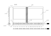
- a volume-type holographic recording material 102 having an optical refractive index of about 1.5 is bonded to a colorless and transparent acrylic substrate 101 having an optical refractive index of about 1.5 and a thickness of 5 mm without using air.
- another volume type holographic recording material 103 is similarly bonded to the recording material at a predetermined position different from the medium 102 on which the image hologram is recorded without passing air.
- a diffusion light source having a predetermined diffusion angle with a predetermined diffusion angle for example, 532 nm
- parallel light of the light of that wavelength is transmitted into the medium 60.
- a reflection-type holographic diffraction grating 104 that reflects at an angle is formed.
- Such a diffraction grating can be created by diffusing a laser having a wavelength close to that of the LED used and recording interference fringes that interfere with parallel light propagating at a critical angle in the medium on a volume hologram material. is there.
- This holographic diffraction grating is formed on the same medium with 16 gaps in the direction orthogonal to the propagation direction of the light in the medium, with one unit being a square shape of about 17.3 mm square.
- the green LED 105 is arranged on the opposite side of the attachment surface of the substrate 101 so as to face the center of the unit holographic diffraction grating while maintaining a predetermined distance.
- the LED is formed as a wired SMD (SURFACE-MOUNT DEVICE) type on the tape-like substrate 106, and the same number as the holographic diffraction grating is arranged at the same 17.3 mm pitch as that of the holographic diffraction grating. Has been.
- the light propagation will be described by paying attention only to the eighth LED (L8) and the holographic diffraction grating (H8) facing it.
- the diffusion angle of the LED is known, and for example, the half value width of brightness is 120 °.
- the position of the light emitting portion of the LED is fixed at a position of several mm from the substrate surface in consideration of the refraction of the acrylic substrate.
- the light from the LED reaches the holographic diffraction grating directly through the acrylic substrate, and the wavelength of the green component propagates in the direction of the edge-lit reproduction type hologram as 60-degree parallel light in the medium.
- the illumination light in the medium reaches the same direction everywhere in the propagation direction.
- This holographic diffraction grating is designed to propagate as parallel light into the medium when illuminated by a predetermined diffused light source. Therefore, the parallel light is 17.3 mm wide and has a strip shape in the X8 region. To reach.
- the image reproduction hologram has been described as a reflection type edge-lit reproduction type holographic stereogram, but is not limited to a stereogram, and may be a hologram that irradiates a real object with a laser.
- the hologram including the holographic stereogram is collectively referred to as a hologram.
- the image observed by the image reproduction hologram includes a stereoscopic image, a moving image that changes depending on the viewpoint, a two-dimensional still image, a pattern, a uniform color, and the like.
- the reflective type has higher wavelength selectivity than the transmissive type, in principle, the transmissive type, that is, the type attached to the observer side of the substrate can also be applied.
- the transparent substrate has been described using an acrylic material, but it is not limited to glass, but also polymers such as polyethylene terephthalate (abbreviated as PET), polycarbonate, polyamide, and triacetylcellulose (abbreviated as TAC). Material may be used.
- the hologram material may be a silver salt material, dichromated gelatin or the like in addition to a photopolymer. Hologram materials generally have an optical refractive index of about 1.3 to 1.7, and an extra hologram is not formed if the optical material does not have an optical interface with the base material. desired. When using total reflection, the substrate needs to be made of a transparent material having an optical refractive index of 1.3 or more.
- the propagation angle in the medium has been described as 60 degrees, the present invention is not limited to this. However, in the case of realizing the edge lit reproduction type, propagation at an angle exceeding the critical angle is essential.
- the light source has been described as an SMD type LED, it may be a shell type or FLUX type LED. Further, a lamp such as a laser diode, xenon, or krypton may be used.
- the wavelength reproduced from the light source has been described as green, but it may be red or blue, or white.
- the emission wavelength band is narrower than that of an LED, an image quality with little chromatic dispersion can be obtained. Moreover, since it has good point light source properties, it is relatively easy to make parallel light. In the case of a semiconductor laser, since the divergence angle is generally different in the orthogonal direction, the beam is often a beam whose aspect ratio is not 1: 1.
- the holographic diffraction grating disposed opposite to the light source can be designed so as to be converted into an ideal aspect ratio in consideration of the direction in which the light is guided.
- the light intensity is high in the central part and the peripheral part is low as in the Gaussian distribution.
- the holographic diffraction grating arranged facing the light source so that the central part has low diffraction efficiency and the peripheral part is high, the diffracted light intensity can be made as uniform as possible.
- the same function can be used to place a gradation mask in the illumination light path, or to apply data correction to the hologram image to be reproduced in advance. You can also follow.
- the holographic diffraction grating has a function of diffusing less than about 5 degrees only in the light propagation direction without diffusing in the direction perpendicular to the light propagation. If the brightness changes sharply at the boundary where the total number of reflections changes, it will be difficult to see the hologram image, so there is an effect of making the boundary inconspicuous.
- the image is diffused in the parallax direction, the deep image becomes blurred. However, since the image is not diffused in that direction, the image can be reproduced without being blurred.
- a one-dimensional diffusion plate may be inserted in the optical path.
- the purpose of the one-dimensional diffuser plate can be achieved by using a lenticular lens, a reflective mirror deposited on the back surface of the lens, a transmissive holographic diffraction grating, or the like.
- This holographic diffraction grating and another one-dimensional diffusion plate may be used in combination.
- the image hologram can be full color and the light source can be white light.
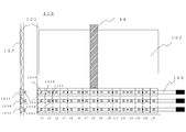
- a second embodiment, a full color display 110 will be described with reference to FIG.
- Volume type holographic recording material is bonded to the same acrylic substrate 101 without air through the three types of red at 103A, green at 103B, and blue at 103C.
- Reflective holographic diffraction gratings 104A, 104B, and 104C are configured to diffract red, green, and blue light, respectively. Corresponding positions are a red LED at the position of 105A, a green LED at the position of 105B, and a blue LED at the position of 105C.
- the hologram image was synthesized with the material 102 on which the hologram image was recorded. Light is propagated to reproduce the hologram image.
- the order of arrangement of red, green, and blue does not have to be this.
- the wavelength selectivity increases, so if the crosstalk is negligible in the wavelength distribution of red, green, and blue, even if the diffraction gratings of these colors partially or completely overlap. good. That is, the holographic diffraction grating may be formed at the same location by using an LED in which red, green, and blue light emitting elements are incorporated in one chip. This is because if the diffraction gratings of other colors do not meet the Bragg diffraction conditions, they are not affected and propagate by total reflection.
- the viewing angle of the hologram is centered on the normal direction of the surface, but the image may be reproduced at another angle.
- the LED when placed on the surface of a bank ATM touch panel, the LED is normally off and you do not notice the presence of the hologram display, but the LED is illuminated and an advertisement is displayed during the withdrawal process waiting time. May be.
- the viewing angle is configured with a viewing angle of about 15 °, for example, about 15 ° below the normal direction of the screen, the viewer looks better from below.
- the optical refractive index of the material in between should be matched with the refractive index of the base material or the hologram recording material as much as possible. If there is a difference in refractive index, an extra hologram may be formed due to reflection at the boundary surface, or total reflection may occur depending on the angle in the medium, and a desired hologram image may not be formed. It is better to keep the difference below.
- the size of the holographic diffraction grating is designed based on the relationship between the thickness of the base material and the angle in the medium. In order to increase the overlap part intentionally and make the boundary inconspicuous, it may be made larger.
- the diffraction grating need not be square. However, when a light source such as an LED that has no difference in vertical and horizontal directivity angles is used, the vertical and horizontal spread angles are the same, so the vertical and horizontal sizes are often generally the same. The reason why it is not a circle but a quadrangle is that a gap is not formed when it is connected, which is preferable, but is not limited thereto.
- the distance between the element diffraction gratings that is, the distance between the light sources can be freely selected in consideration of uniformity and the like.
- the hologram is subject to material shrinkage and expansion after recording depending on the recording material. As a result, during reproduction, the diffraction wavelength and diffraction angle change from those during recording.
- it is important to record in advance at different angles and wavelengths so that the properties of the light can be secured during reproduction based on this change. is there.
- each element diffraction grating has a holographic structure in which substantially parallel light is generated in the thickness direction of the substrate and divergent light is generated in the direction perpendicular to the propagation direction.
- a diffraction grating is formed, and the directivity angle differs depending on each element diffraction grating as shown in the figure.
- the LED light sources facing the holographic diffraction grating do not need to be aligned.
- a fourth embodiment of the input interface device 200 will be described with reference to FIG.
- the colorless and transparent substrate 201 is provided with an image hologram medium 202 in optical contact with the center and the side opposite to the observer, and in four surrounding directions, reflective holographic diffraction gratings 204A, 204B, and 204C. 204D are arranged in optical contact with each other, and the light sources 205A, 205B, 205C, and 205D are close to corresponding positions.
- Reference numeral 205A denotes an LED containing a red component.
- LED 205 When the LED 205 is turned on, light is propagated through the substrate 201 by the opposing reflective holographic diffraction grating 204A, and reaches the image hologram medium 202 to reproduce a red hologram image.
- 205B, C, and D are also red LEDs, and have a structure that allows the same hologram medium 202 to be irradiated as substantially parallel light at different angles from different angles by the diffraction gratings 204B, C, and D.
- 205A, B, C, and D are sequentially turned on at different timings, different images are reproduced from the same place in 202.
- This interface is an input device.
- a switch (not shown) is pressed to operate the A function, and the B hologram image is played back.
- the function of B works (the same applies to C and D).
- it is a single switch, it can be a switch having a plurality of functions.
- the light source is only 205A, and it can be rotated relative to a member in which the holographic diffraction grating and the image hologram medium are integrated. By relatively rotating these members by 90 degrees, The holographic diffraction grating facing 205A can be changed and fixed to any one of 203A to D.
- 205A is turned on when 205A faces 203A, an image corresponding to A is reproduced by 202, and when the switch is pressed at that time, A functions.
- 205A faces 203B, an image corresponding to B is reproduced, and the switch as B functions.
- C, D and four different types of switches can be functioned as one. Although four types have been described, any number of two or more can be applied as long as no image crosstalk occurs.
- the concept of switching a plurality of light sources incident at a plurality of different incident light angles to display different hologram images and making different input interfaces at the pressed timing is as follows.
- the light may be incident directly from the end face without being deflected by the holographic diffraction grating.
- a parallel plate is assumed, but it may be cylindrical or have a curvature.
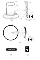
- a cylindrical display device 500 according to a fifth embodiment will be described with reference to FIG.
- a transparent acrylic cylinder having an outer diameter of 150 mm and an inner diameter of 144 mm, a cylindrical portion having a length of 200 mm, an upper end portion, and a lower end portion are bonded with element holographic diffraction gratings inside without air.
- an edge-lit reproduction type hologram HS is pasted to the center of the cylinder without air.
- the area illuminated by LA1 is only the part of HS1 and does not reach the other part.
- LEDs LA1, LA2,... are similarly arranged from the outside of the cylinder over the entire circumference, thereby reproducing a hologram image in which an image floats in the cylinder.
- Another LED is also arranged from the outer side of the cylinder toward the inner side at positions LB1 to LB.
- the LED in the LA row is turned off and the LED in the LB row is turned on, another image is reproduced.
- the LED may be arranged inside the cylinder, and the holographic diffraction grating may be arranged outside the cylinder.
- the holographic diffraction grating does not have power in the direction parallel to the axis inside the cylinder, and when viewed in a cross section perpendicular to the axis of the cylinder, it reflects a beam with a uniform orientation in the direction passing through the center of the axis. Is made. This maintains continuity even if the number of total internal reflections changes.
- the image hologram is also exposed so that an image without distortion is reproduced when such illumination light is irradiated.
- it may be planar, and when recording a holographic stereogram, the image is distorted in advance in consideration of the curvature of the medium to be pasted.
- Cylindrical holographic stereograms can use multiple light sources according to the present invention, compared to the previous example of multiplex holograms described in the prior art, and the viewer can reproduce bright images without being aware of the light sources. There is an advantage that can be.
- a sixth embodiment will be described as a rotating cylindrical display 600 in FIG.
- the cylindrical hologram described in the fifth embodiment can be rotated about the cylindrical axis.
- the cylinder axis is horizontal, and the three cylinders HX, HY, HZ can rotate independently on the same axis.
- the HX propagates to the inside of the cylinder HX at an angle exceeding a predetermined critical angle by the facing edge-lit holographic diffraction gratings HA1 to HA5, and the hologram recording media HS1 to Reproduced from the HS5 part.
- By turning off LA1 to LA5 and turning on LB1 to LB5, different hologram images are reproduced from the same HS1 to HS5.
- HY and HZ can reproduce HT and HU hologram images using HC, HD, HE, and HF holographic diffraction gratings facing the LC, LD, LE, and LF light sources.
- the cylinders HX, HY, and HZ are independently rotatable about the axis, and when a holographic diffraction grating at another location is positioned at LA1 to LA5, another hologram image is reproduced.
- These cylinders including the hologram medium are transparent, and can be displayed superimposed on characters, patterns, images and the like formed on another rotating body (not shown) arranged concentrically inside.
- the three cylinders may rotate independently, and the hologram image may be reproduced only when images, characters, etc. are aligned vertically and horizontally.
- the light source may be arranged from the outside of the cylinder toward the inside, and the holographic diffraction grating may be arranged on the inner surface side of the cylinder. Conversely, the light source is arranged inside, and the holographic diffraction grating is arranged outside the cylinder. It may be.
- the light source is fixed to the casing and only the cylindrical substrate on which the image hologram and the holographic diffraction grating are arranged has been described, the light source and the holographic diffraction grating are fixed and the image hologram Only the cylindrical base material on which is disposed may rotate. In that case, since it is desirable that the holographic diffraction grating and the cylindrical base material are in optical contact with a material having a combined refractive index because there is no light loss, it is preferable to interpose a liquid. However, as will be described later, if two components cut and separated at an angle where they are not totally reflected are brought close to each other and coupled, the necessary illumination light can be guided with little light loss even if air is present.
- the shape of the medium on which the image hologram is affixed may not be a perfect cylinder but a part thereof.
- a convex shape or a concave shape as viewed from the observer side may be used, or they may be continuously connected, including a parallel plate shape.
- the viewing angle can be widened by bending a part of the edge with a curvature, almost flat.
- a concave shape called an alcove type it is possible to express an image as if it floats in the air.
- the portion that can be seen rearward is almost a flat plate, and the end has a convex curvature when viewed from the outside, thereby deflecting light in the lateral direction. be able to.
- the curvature is given in the uniaxial direction.
- the curvature may be given in the direction perpendicular to it, may be spherical, or may be a part of the sphere.
- an image hologram is recorded with a curvature different from the curvature in the observation state, a previously distorted image is recorded.
- the light emitting portion of the optical element facing the unit holographic diffraction grating is strictly positioned.
- the light emitting unit may be configured such that the relative position changes with time in a range up to the width of the unit holographic diffraction grating.
- a plurality of adjacent LEDs may sequentially emit light, or one light source may physically move relatively.
- FIG. 170 An example 170 in which a plurality of image display units are arranged in the depth direction is shown in FIG.
- different holographic diffraction gratings are formed on different transparent plastic plates of three units. Different unrelated images may be displayed, but different portions of the same object may be displayed as a whole.
- the distances from the light sources 107A, 107B, and 107C to the corresponding holographic diffraction gratings 108A, 108B, and 108C are different, and diffraction gratings having focal lengths corresponding thereto are arranged.
- the light source and the reflective holographic diffraction grating array must be positioned precisely.
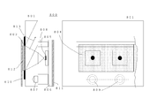
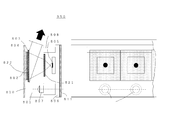
- An example 800 of the structure will be described with reference to FIG.
- a hologram medium 804 in which an array of holographic diffraction gratings 803 is formed is attached to a part of one surface of the transparent plastic plate 801. Since the medium 804 is in contact with the transparent plastic base material 812, the base material serves as a protective layer.
- a number of SMD type LEDs are arranged and wired on the tape-like substrate 806 in accordance with the unit diffraction grating of the holographic diffraction grating array.
- a part of this tape-shaped substrate is formed with a convex shape 807 member, while a plastic material 801 is provided with a concave shape 809 that can be fitted, and these convex portions are fitted into the concave portion during assembly.
- the position is determined by.
- Reference numeral 808 denotes a spacer.
- a magnet 811 is provided on the back side of the tape-shaped substrate, and another magnet 810 is provided from the outside of the holographic diffraction grating, so that a force attracting both the magnets can be generated and fixed.
- the holographic diffraction grating 803 naturally aligns the transparent plastic plate 801 with the holographic diffraction grating in the direction of 813 in the medium. However, it is possible to fix the position and angle with high accuracy by performing exposure and bonding after positioning using the concave portion 809.
- the positioning method is not limited to this, but it is desirable that the positional relationship and angle between the light source and the holographic diffraction grating are uniquely determined.
- a method may be used in which the positioning is roughly performed without any particular positioning, confirmation is made while monitoring the degree of parallel light, and fixing is performed in the best condition.
- the holographic diffraction grating there are various specifications for the holographic diffraction grating, such as the wavelength to be diffracted, the diffraction angle, and the distance to the light source. Because the specifications of holographic diffraction gratings are not always readily apparent, the main specifications are printed on the medium on which holographic diffraction gratings are recorded or on an adjacent substrate that is difficult to separate. It is good to be. As a printing method, various methods such as printing, laser marking, and etching can be considered.
- the shape part used for fitting at 800 is given a feature, and if it is a combination as designed, it is positioned by fitting, but the light source and holographic diffraction grating are set in a combination different from the design When trying to do so, it may be understood that the fitting does not fit and that it cannot be used.
- the light from the light source reaches the opposing holographic diffraction grating at a predetermined angle and spread angle. It is desirable to transmit the material 801 outside or absorb it with a black member or the like so that it does not propagate inside the plastic substrate 801 or cause scattering.
- the vicinity of the medium of the 801 holographic diffraction grating and the back surface thereof are blackened. Specifically, a black paint or a black adhesive material is formed.
- the light from the light source is irradiated to the opposing holographic diffraction grating, it is not irradiated to the adjacent diffraction grating.
- the light reaching the adjacent diffraction grating propagates the light having a predetermined angle and wavelength to the inside of the plastic substrate 801.
- the contrast is deteriorated or multiple images are reproduced. This is because it may cause blurring or blurring.
- a black material wall 820 is provided between adjacent holographic diffraction gratings.
- the LED side of the plastic substrate or the holographic diffraction gratings is provided. Louver films 821 and 822 are arranged between the medium or both.
- the base material on which the image hologram is arranged may be a touch panel, and may be an input interface. Moreover, it can be arranged on the surface of a smart phone, a PC monitor, etc., and it can prevent the function of the input interface from being disturbed while serving as a protective film.
- traffic signals are installed slightly downward, but do not restrict the field of view greatly depending on the direction, and emit light in areas that are not touched by anyone.
- FIG. 11 in a place where a traffic signal is installed at a place where the main road meets the main road, the driver in the H1 area traveling on the main road and the side road Because the angle is small with the driver in the S1 region traveling on the road, it may be erroneously recognized.
- a viewing angle control plate called a louver is arranged in front of the signal.
- the presence of such a louver limits the amount of light that reaches the driver's eyes, making it dark and difficult to see.
- the visible position can be strictly defined, and there is an advantage that the visible position can be concentrated and brightened brightly by narrowing the viewing angle. In order to obtain the same brightness, the power consumption can be reduced if a small number of LED light sources can be used.
- signal information of different colors in a plurality of directions can be emitted by one signal device, which leads to a reduction in the number of signal devices themselves and has a great merit.
- Reference numeral 151 denotes a transparent plastic plate or glass plate, and there is an image hologram that diffracts green, yellow, and red light in a specific direction from the left at the center, and a holographic diffraction grating array 154A at the upper and lower portions, respectively.
- L1 to L5 are green LED light sources, and the holographic diffraction grating 153A facing the LED light source has a function of propagating the inside of the transparent substrate 151 at about 60 ° in the upper medium, that is, at an angle greater than the critical angle.
- the light sources L1 to L5 are turned on, the light reaching the image hologram medium 152 emits green light in the direction of LL in the G portion.
- the same image hologram 152 is irradiated with the light propagating from above in the substrate, the same G portion is made to emit green light in the direction of RR.
- the LED light source R5 is turned on, light is emitted in the direction of RR from the same region.
- LED light sources L11 to L15 and R11 to R15 are red or LEDs containing a red component, and light sources Rx and Lx (x is 1 to 16) are turned on at different timings, so In the direction, it is possible to shine a red hologram image in the R region.
- FIG. 13 is a view of the intersection of the five-way road viewed from the sky.
- FIG. 14C shows a visual field region viewed from above.
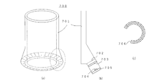
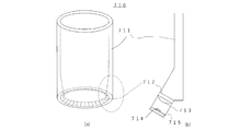
- Light introducing paths are formed at the ends of the cylinders 701 and 711, and can be made substantially parallel light in the medium from the inside to the outside of the cylinder or from the outside to the inside, respectively.
- the incident surface 702 is a flat surface, and a substantially parallel light may be incident in advance using a light source and a collimator lens, or may be a continuous surface such as a part of a conical surface. Or you may make it a 1st reflective surface fulfill
- FIG. 16 an example in which a unit in which the light source 704 and the collimator Fresnel lens 703 are integrated is brought close to the incident surface 702 is shown.
- 710 illustrated in FIG. 17 an example in which a convex aspherical surface 713 is formed on the surface of the incident surface 712 in order to make the light from the light source 714 parallel.
- the arrangement on the outside has the advantage of being easy to configure because the distance between adjacent light sources can be widened, while the arrangement on the inside has the advantage of being compactly accommodated.
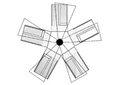
- the fan-shaped development as shown in FIG. This is not necessarily the case if a holding mechanism for directing light from the light source in a predetermined direction is created. Further, an edge-emitting tape LED can also be used.
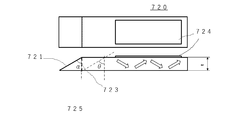
- a surface 721 having an angle ⁇ with respect to the incident surface normal is formed on the opposing surface, and mirror deposition is performed on the surface.
- it may be deflected in the direction of the angle ⁇ at which the light is totally reflected in the medium by bonding a mirror.
- the member of the light introducing portion and the member on which the edge lit hologram 724 is formed are desirably integrated, but there is no functional problem even if they are separated on the surface 723.
- the light source and the light introducing member are made of relatively expensive parts to make an illumination device for an edge-lit hologram, and the medium on which the edge-lit hologram is formed can be made at a low cost with a simple parallel plate.
- the surface 723 needs to have high surface accuracy on both the light introducing member side and the edge-lit hologram member side, and preferably has a flatness of ⁇ or more. Since it does not propagate at the angle of reflection, it is not always necessary to perform index matching. Of course, index matching may be performed using a transparent liquid, a gel material, silicone rubber, or the like.
- the cylindrical edge-lit hologram 730 is formed with a reflection hologram 733 that reproduces a diffracted image centered substantially perpendicularly to the outside of the cylinder when the inner surface of the transparent acrylic thin cylinder is irradiated in the direction of 739 of about 60 degrees in the medium.
- a black film for increasing the contrast is provided inside the hologram layer through an air layer. In order to increase the contrast, it is possible to attach a black film or the like via an adhesive without using air, but if you want to reproduce the hologram image with higher-order reflected light, the black film absorbs it. To avoid the air layer.
- a large number of laser modules 743 in which a semiconductor laser 735 and a collimator lens 736 are integrated are arranged on the pedestal 740 at equal intervals from the outside of the cylinder toward the center, and enter as substantially parallel light from the outside of the light-introducing acrylic cylinder 741.
- the circular beam becomes a rectangular beam.
- a diffusion plate filter 742 that slightly diffuses light only in the vertical direction is inserted immediately before entering the cylinder.
- the facing surface has an inclination of about 60 degrees in the cross section and is subjected to mirror vapor deposition 734, so that it propagates in the direction of 60 degrees in the medium.
- the cylindrical hologram 730 combined with the light-introducing acrylic cylinder 741 has the same inner diameter and outer diameter, and when the light source is turned on by fitting without being displaced at the opening, the optimum illumination light reaches the edge-lit state.
- the hologram image arrives and is reproduced.
- a switch (not shown) is built in 740, and may be turned on for a certain time, for example, about 3 minutes after the cylinder is mounted, and then turned off.
- the cylindrical hologram display 750 includes a laser module 763 inside a thin cylinder 751 to which an edge-lit hologram 753 is attached.
- the red laser 755 and the collimator lens 756 are adjusted so as to be able to oscillate parallel light, and light emitted from the laser module in the substantially cylindrical axis direction is irradiated onto the thin cylinder by the conical mirror 761.
- the layer structure of the hologram medium affixed to the cylindrical inner surface is a transparent adhesive 764, a hologram recording medium 753, a transparent protective base material layer 757, and a black shielding layer 760 from the inner side to the inner side of the cylindrical surface.
- the shielding cap 758 and the pedestal 752 are both made of a light shielding member or a diffusing member so that the laser beam does not leak outside without being diffused.
- Each of 730 in FIG. 19 and 750 in FIG. 22 was manufactured by sticking a hologram-recorded medium exposed and produced by another hologram recording apparatus to the inside of a cylinder or a part of the cylinder, that is, the side having a small curvature.
- a roller having a smaller curvature than the inner curvature of the cylinder was used, the bonded surfaces were brought close to each other while being lightly bonded, and the rollers were pressure bonded to prevent air from entering.
- the bonding method is not limited to this, but a cylinder made of a transparent base material having an optical refractive index of 1.3 or more with a curvature, or an edge-lit hologram attached to a part of the cylinder, has a total reflection angle in the base material.
- the point of the present invention is to reproduce the hologram image as a reflection type by the illumination light guided in the above, but it is common to reproduce the edge-lit hologram as a transmission type, but by adopting the reflection type reproduction, Both wavelength selectivity and angle selectivity are increased compared to the transmission type, and a high-quality hologram image can be reproduced. .
- the curvature of the medium when the edge-lit hologram is recorded may be different from the curvature of the cylindrical surface attached at the time of reproduction. It was possible to express a natural three-dimensional effect by performing exposure after applying image processing correction based on the curvature to be finally applied.
- A, B, C, and D are areas of edge-lit holograms that are illuminated from one light source, and the abc in the area illustrates the direction of light beams that each light source is partially directed to. Yes. Although c in A and a in B are adjacent to each other, the reproduced images are not discontinuous because the light directions are aligned. On the other hand, since the direction of light is different after C c and D, the reproduced image is discontinuous.
- the image can be made continuous by compensating and predistorting the image to be reproduced.
- image correction can be performed not only in the horizontal direction but also in the vertical direction. That is, when the illumination is performed by performing total reflection multiple times as the reproduction light of the edge-lit hologram, the direction of the light at the end of the light beam is different between the light reflected n times and the light reflected (n + 1) times on the same surface. What may be different means that the hologram image to be displayed is distorted in advance. When illuminating with total reflection multiple times, light that has not gradually contributed to hologram reproduction can be illuminated with higher-order reflected light, but the amount of light gradually decreases as the number of reflections increases. In order to correct this, correction was performed in advance by changing the diffraction efficiency itself of the hologram image between a location near and far from the light source.
- an optical functional element such as a gradation mask is inserted in the optical path to compensate for this. Measures such as applying correction can be taken. That is, as shown in FIG. 20A, the end portion becomes darker than the central portion due to the Gaussian distribution, and if light from a plurality of light sources is adjacent or reflected a plurality of times in the waveguide direction, adjacent light is Since it has a distribution, it was corrected and uniformed.
- a filter whose transmittance gradually changes depending on the position so that the transmittance of the central portion is 1 ⁇ 2 that of the end portion is used as an optical path. Inserted inside.
- the diffraction efficiency at the center is set to about 1 ⁇ 2 of the diffraction efficiency at the end.
- the position of the light deflection device which is an illumination device, and the edge-lit hologram is clear, the bright and dark positions are known information, so the image of the edge-lit hologram to be recorded is compensated in advance.
- the dark illumination was bright and the bright illumination was dark, and the diffraction intensity of the hologram image was changed. Any one of the above methods may be used, or may be used in combination.
- all the batteries, light sources, etc. may be housed inside the cylinder, and the image may be reproduced when the cylinder rolls.
- edges-lit hologram When the edge-lit hologram is formed in a cylindrical shape so that it can rotate at a relative speed to the light source unit, effects and functions can be added by providing variations in the light source control. For example, it is assumed that the edge-lit hologram rotates slowly at about 1 rotation per minute while the light source rotates coaxially at 120 rotations per minute. Assuming that the light source is always lit, there is an advantage that if the fixed light source is left ununiform or speckle noise is averaged, and uniform image reproduction can be performed. Further, by rotating RGB LEDs or lasers, it is possible to reproduce a natural full-color image by overlapping colors that have been broken with a fixed light source.
- the point of the present invention is that the image edge-lit hologram is illuminated by area division or time division using a plurality of light sources so that the entire hologram image can be observed.
- light used for image reproduction is configured to pass through the holographic diffraction grating only once on the transparent substrate. This is because, when the light returned by the total reflection is irradiated again on the holographic diffraction grating, the parallel light property of the beam for reproducing the disturbed image hologram is deteriorated and the image quality of the image hologram is deteriorated.
- a stereoscopic image can be displayed when not in use.
- It can also be a trophy, medal, certificate, shield, name tag, nameplate, signboard, etc. It may be applied to an aquarium or other aquarium or a tropical fish tank. You may apply to some bottles, such as a plastic bottle, a glass bottle of liquor, a glass bottle of a seasoning, a glass, etc. A new value can be added by applying an edge-lit hologram to the surface of a cylindrical glass speaker or AI speaker.
- a laser pointer or LED pointer can be created without using a collimator lens if a medium having an optical refractive index of 1.3 or more with a reflective holographic diffraction grating is disposed immediately after a light emitting unit such as an LED or a laser light source. be able to. A reduction in size, weight and cost can be achieved.
- linear parallel light can be produced only by the process of bonding the tape LED in which a plurality of light sources are arrayed to a transparent plastic substrate.
- the example 950 shown in FIG. 10 is configured so as to be emitted toward the air from a plane substantially perpendicular to the traveling direction while minimizing loss after collimated light in the plastic medium. This linear light source can also be applied to signs that illuminate buildings and the like.
- the holographic diffraction grating that deflects the light from the light source has been mainly described for the reflection type.
- the reflection type increases the wavelength selectivity and the angle selectivity, and the performance as a light filter increases.
- the refractive index modulation degree and thickness of the material are optimized, the image hologram It can be used for reproduction.
- the present invention has been described so far by using a holographic diffraction grating, illuminating an edge-lit reproduction hologram using a plurality of light sources, and a combination thereof. Needless to say, the present invention can be applied to various modified examples as long as the effects can be obtained.
- 1 is an illumination apparatus (first embodiment) of an edge-lit reproduction type hologram to which the present invention is applied. It is the illumination device (2nd Example) of the full color edge lit reproduction
Landscapes
- Physics & Mathematics (AREA)
- General Physics & Mathematics (AREA)
- Optics & Photonics (AREA)
- Engineering & Computer Science (AREA)
- Theoretical Computer Science (AREA)
- Geometry (AREA)
- Business, Economics & Management (AREA)
- Accounting & Taxation (AREA)
- Marketing (AREA)
- Holo Graphy (AREA)
- Diffracting Gratings Or Hologram Optical Elements (AREA)
Abstract
Description
該透明媒質に臨界角を超えた光を入射し、該透明媒質を通して反射型のホログラム像を観察する、画像再生方法を提供することで上記課題を解決する。
同様に全周に渡って円筒外部からLEDが配されておりこれにより円筒内に像が浮かぶようなホログラム画像が再生される。LB1~の位置にも別のLEDが円筒外側から内側に向かって配されており、LA列のLEDを消してLB列のLEDを点灯すると、別の画像が再生される。上記の例とは逆に、LEDは円筒内側に配置し、ホログラフィック回折格子が円筒外側に配置されていても良い。いずれの場合も、ホログラフィック回折格子は円筒内部では、軸と平行の方向にパワーを持たず、円筒軸に垂直な断面でみたときには軸中心を通る方向の、向きの揃ったビームを反射するように作られている。これにより内部での全反射回数が変わっても連続性が保たれる。画像ホログラムもそのような照明光が照射されたときに歪みのない像が再生されるように露光されている。画像ホログラムを記録する際は平面状であってもよく、ホログラフィックステレオグラム記録の際には、貼られる媒体の曲率を考慮した上で、予め画像を歪ませておく。
102、202・・・画像ホログラム用記録媒体
103、203、803・・・反射型ホログラフィック回折格子用媒体
104、204、804・・・ホログラフィック回折格子
105、205、805・・・LED
106・・・LED基板
LA、LB、LC、LD、LE、LF・・LED
HA,HB、HC、HD、HE、HF・・ホログラフィック回折格子
700、710、730、750円筒型ホログラムディスプレイ
701、711、731、751円筒
704、715、735、755光源
761円錐ミラー
Claims (27)
- 光源発光部と、光学屈折率1.3以上の略透明媒質と、該媒質の一部に空気を介さず配されたホログラフィック回折格子を有し、
光源発光部から光学屈折率1.3以上の媒質内に入射したある発散角をもった光を、ホログラフィック回折格子により発散角と偏向角を共に変化させて該回折格子の面に対して臨界角を超える所定の角度方向に反射することを特徴とする光偏向装置。 - 上記、ホログラフィック回折格子は反射型であって、媒質内で反射した光は略平行光となるように反射させることを特徴とする請求項1記載の光偏向装置。
- 上記、回折により偏向した光は略矩形形状となっていることを特徴とする請求項1記載の光偏向装置。
- 上記、発散角、発光波長成分などが略同一の、少なくとも2つの光源を光導波方向と垂直方向に配し、各々の光源に対して、対向する位置にホログラフィック回折格子を配することを特徴とする請求項1記載の光偏向装置。
- 上記、異なる波長成分をもつ少なくとも2種の光源を光導波方向と平行に配し、それぞれの光源に正対した反射型ホログラフィック回折格子を有することを特徴とする請求項1記載の光偏向装置。
- 上記、光の導波方向と垂直方向には拡散させず、光の導波方向にのみ拡散させる光学機能を該ホログラフィック回折格子に持たせたことを特徴とする請求項5記載の光偏向装置。
- 少なくとも2つの光源発光部と、光学屈折率1.3以上の略透明媒質と、各々の光源に対してその間隔と略一致した間隔で配された屈折光学機能素子と、該光源からの光を隣接する屈折光学機能素子に入射させないように配した隔壁を有し、該光学屈折率1.3以上の媒質内で臨界角を超える所定の角度方向に光偏向装置。
- 上記、光の導波方向と垂直方向には拡散機能を持たず、光の導波方向にのみ拡散機能を持たせた光学機能素子を光路中に配したことを特徴とする請求項7記載の光偏向装置。
- 光学屈折率1.3以上の略透明媒質上に形成された臨界角を超える角度で照射再生するホログラムを有し、光の伝搬方向と略垂直方向に配置された少なくとも2つの光源からの光を回折または屈折によって略平行光化し、所定の角度でホログラムを照射することを特徴とする画像表示装置。
- 上記、該光学屈折率1.3以上の媒質は略平行平板であることを特徴とする、請求項9記載の画像表示装置。
- 上記、該光学屈折率1.3以上の媒質は略円筒、または略円筒の一部であることを特徴とする、請求項9記載の画像表示装置。
- 上記、ホログラムが形成された略円筒形状の部品は、円筒軸を中心に回転可能となっていることを特徴とする、請求項11記載の画像表示装置。
- 上記、略円筒の少なくとも一部にホログラム媒体が貼付された透明円筒を有し、略平行光として該円筒外側から面に略鉛直方向から入射した光を、ミラーまたはホログラム回折格子にて、媒質内部で所定の全反射角度に伝搬するようにしたことを特徴とする、請求項11記載の画像表示装置。
- 上記、光偏向装置の光学屈折率1.3以上の媒質の部品と該ホログラムとは光学的に一体化されていることを特徴とする、請求項9記載の画像表示装置。
- 上記、光偏向装置の一部である光学屈折率1.3以上の媒質の部品と、該ホログラムが形成された光学屈折率1.3以上の別の媒質の部品とは着脱可能であり、両部品の断面が略同一形状した面どうしを近接させて光導波させることを特徴とする請求項9記載の画像表示装置。
- 上記、複数の光源は、同一のフレキシブル基板に配されており、光学屈折率1.3以上の媒質の面まで一定距離を保つように該基板を固定できるようになっていることを特徴とする、請求項9記載の画像表示装置。
- 上記、複数の光源からの光が、該ホログラムに照射される隣接領域において、照度分布に応じてホログラム像の回折強度を逆補正しておくことを特徴とする請求項9記載の画像表示装置。
- 上記、複数の光源からの光が、該ホログラムに照射される隣接領域において、光の平行度に応じてホログラム像の再生角度を逆補正しておくことを特徴とする請求項9記載の画像表示装置。
- 上記、組み合わされるべき画像記録媒体の表示色、波長、照明角度、発散角、逆補正用データの少なくともひとつの情報が記載されていることを特徴とする請求項4、5、8のいずれかに記載の光偏向装置。
- ホログラム画像の記録媒体であって、画像表示ホログラム媒体と、光偏向ホログラム媒体とが光学屈折率1.3以上の略透明媒質と光学的に一体化されており、該光偏向ホログラム媒体に発散光源を所定の位置に近接配置すると、該画像表示ホログラムが適正に再生される画像記録媒体。
- 上記、該媒体の一部に、光源の種類、波長、発散角、光学的補償データに関する情報の少なくとも一つの情報に応じた異なる形状が形成されており、光源側に施された形状と嵌め合わされることにより位置、角度が固定されることを特徴とする請求項20記載の画像記録媒体。
- 上記、該媒体の一部には、照明されるべき光源の種類、波長、発散角、光学的補償データに関する情報のうちの少なくともひとつの情報が明記してあることを特徴とする請求項20記載の画像記録媒体。
- 光学屈折率1.3以上の略透明媒質と、該媒質の表面に空気を介さずに配されたホログラム媒体と、該ホログラム媒体を該媒質内側から臨界角を超える角度で伝搬する少なくとも2つの照明用光源を有することを特徴とする画像表示装置、または信号装置。
- 上記、さらに、少なくとも2つの照明用光源を切り替える手段を有し、同一の場所から異なる画像を表示することを特徴とする請求項23記載の画像表示装置、または信号装置。
- 上記、さらに、少なくとも2か所の異なる場所から、該ホログラム媒体を観察したときに、少なくとも2つの異なる状態を認識できるための、照明用光源の切替手段を有することを特徴とする請求項23記載の画像表示装置、または信号装置。
- 上記、該ホログラムから回折される光の色は、少なくとも2種類であって、どこから見ても多くとも1つの色しか認識できないような照明用光源の切替手段を有することを特徴とする請求項25記載の画像表示装置、または信号装置。
- 曲率をもった円筒、または円筒の一部の光学屈折率1.3以上の略透明媒質の面に対し、
別工程で制作されたエッジリットホログラムを空気層なく貼付し、
該透明媒質に臨界角を超えた光を入射し、
該透明媒質を通して反射型のホログラム像を観察する、画像再生方法。
Priority Applications (3)
| Application Number | Priority Date | Filing Date | Title |
|---|---|---|---|
| EP18808925.4A EP3647857A4 (en) | 2017-05-29 | 2018-04-25 | OPTICAL DEFLECTOR, IMAGE DISPLAY DEVICE, SIGNAL DEVICE, IMAGE RECORDING MEDIUM AND IMAGE REPRODUCTION METHOD |
| US16/617,043 US20210318658A1 (en) | 2017-05-29 | 2018-04-25 | Optical deflection device, image display device, signal device, image recording medium, and image reproduction method |
| JP2019522034A JP7132629B2 (ja) | 2017-05-29 | 2018-04-25 | 光偏向装置、画像表示装置、信号装置、画像記録媒体、及び、画像再生方法 |
Applications Claiming Priority (2)
| Application Number | Priority Date | Filing Date | Title |
|---|---|---|---|
| JP2017-105948 | 2017-05-29 | ||
| JP2017105948 | 2017-05-29 |
Publications (1)
| Publication Number | Publication Date |
|---|---|
| WO2018221091A1 true WO2018221091A1 (ja) | 2018-12-06 |
Family
ID=64455372
Family Applications (1)
| Application Number | Title | Priority Date | Filing Date |
|---|---|---|---|
| PCT/JP2018/016747 Ceased WO2018221091A1 (ja) | 2017-05-29 | 2018-04-25 | 光偏向装置、画像表示装置、信号装置、画像記録媒体、及び、画像再生方法 |
Country Status (4)
| Country | Link |
|---|---|
| US (1) | US20210318658A1 (ja) |
| EP (1) | EP3647857A4 (ja) |
| JP (1) | JP7132629B2 (ja) |
| WO (1) | WO2018221091A1 (ja) |
Cited By (3)
| Publication number | Priority date | Publication date | Assignee | Title |
|---|---|---|---|---|
| CN115023638A (zh) * | 2020-03-31 | 2022-09-06 | 株式会社藤仓 | 光运算装置、以及光运算装置的制造方法 |
| US11662603B2 (en) * | 2019-07-02 | 2023-05-30 | Hyundai Mobis Co., Ltd. | Three-dimensional image display apparatus |
| JP7562128B2 (ja) | 2020-08-18 | 2024-10-07 | 株式会社アーティエンス・ラボ | ホログラム画像再生装置 |
Families Citing this family (10)
| Publication number | Priority date | Publication date | Assignee | Title |
|---|---|---|---|---|
| US12352985B2 (en) * | 2020-01-22 | 2025-07-08 | Sony Group Corporation | Image display apparatus |
| DE102021200543A1 (de) * | 2021-01-21 | 2022-07-21 | Carl Zeiss Jena Gmbh | Miniaturisierte holographische Anzeige |
| WO2022238109A1 (de) * | 2021-04-27 | 2022-11-17 | Carl Zeiss Jena Gmbh | Optisches system für schwebende hologramme |
| EP4421544A4 (en) * | 2021-10-18 | 2025-11-12 | Fujikura Ltd | OPTICAL COMPUTER DEVICE AND MANUFACTURING PROCESS |
| DE102022202041A1 (de) * | 2022-02-28 | 2023-08-31 | Carl Zeiss Jena Gmbh | Holographische leuchtvorrichtung mit entlang einer zentralen achse angeordnetetn elementen und einkoppelfläche im randbereich |
| DE102022104965A1 (de) * | 2022-03-02 | 2023-09-07 | Carl Zeiss Jena Gmbh | Kompakte lichttechnische vorrichtung zur rekonstruktion eines hologramms |
| DE102022106488B3 (de) * | 2022-03-21 | 2023-07-06 | Audi Aktiengesellschaft | Anzeigevorrichtung für ein Fahrzeug |
| CN115793424B (zh) * | 2022-11-04 | 2025-06-20 | 四川大学 | 一种光学柱面全息显示的放大与质量提升方法 |
| KR20240085348A (ko) * | 2022-12-07 | 2024-06-17 | 삼성디스플레이 주식회사 | 표시 장치 |
| DE102023103962A1 (de) * | 2023-02-17 | 2024-08-22 | Carl Zeiss Jena Gmbh | Vorrichtung zur Erzeugung einer polychromatischen holographischen Abbildung in einer Sitzblende |
Citations (11)
| Publication number | Priority date | Publication date | Assignee | Title |
|---|---|---|---|---|
| JPH03297003A (ja) * | 1990-04-16 | 1991-12-27 | Nippondenso Co Ltd | ホログラムを用いた表示装置 |
| JPH08507879A (ja) * | 1993-02-26 | 1996-08-20 | イエダ リサーチ アンド デベロツプメント カンパニー リミテツド | ホログラフィー光学装置 |
| JPH10254388A (ja) | 1997-03-14 | 1998-09-25 | Sony Corp | 表示装置 |
| JP3066613U (ja) * | 1999-04-30 | 2000-03-03 | 高男 東 | 円筒型ポータブルショーケース |
| JP2001284718A (ja) | 2000-03-31 | 2001-10-12 | Sony Corp | 外部共振型レーザ |
| JP2002040911A (ja) | 2000-07-19 | 2002-02-08 | Sony Corp | 画像再生装置及び画像再生方法 |
| JP2010039086A (ja) | 2008-08-01 | 2010-02-18 | Sony Corp | 照明光学装置及び虚像表示装置 |
| WO2011033906A1 (ja) | 2009-09-18 | 2011-03-24 | パイフォトニクス株式会社 | パターン形成用照明装置 |
| JP2012042654A (ja) | 2010-08-18 | 2012-03-01 | Sony Corp | 表示装置 |
| US20150220058A1 (en) * | 2014-02-03 | 2015-08-06 | Samsung Electronics Co., Ltd. | Mobile device capable of displaying hologram and hologram display method |
| JP2015230410A (ja) | 2014-06-05 | 2015-12-21 | 株式会社エガリム | ホログラム用照明装置、ホログラム表示装置、ホログラフィック光学素子の作製装置及び作製方法 |
Family Cites Families (8)
| Publication number | Priority date | Publication date | Assignee | Title |
|---|---|---|---|---|
| JP3709648B2 (ja) * | 1997-03-11 | 2005-10-26 | ソニー株式会社 | 画像再生方法及び画像再生装置 |
| ITTO20030853A1 (it) * | 2003-10-30 | 2005-05-01 | Ct Ricerche Plast Optica S R L | Dispositivo luminoso, in particolare pannello luminoso per segnaletica o informazione al pubblico, o fanale di autoveicolo. |
| US20070098326A1 (en) * | 2005-11-01 | 2007-05-03 | Kuo Huei P | Light guide screen with louver device |
| US10210793B2 (en) * | 2008-03-11 | 2019-02-19 | Robe Lighting S.R.O. | Array of LED array luminaires |
| US20110304798A1 (en) * | 2010-06-10 | 2011-12-15 | Sharp Kabushiki Kaisha | Illumination device and liquid crystal display device |
| WO2016111707A1 (en) * | 2015-01-10 | 2016-07-14 | Leia Inc. | Grating coupled light guide |
| CN105182607B (zh) * | 2015-10-12 | 2018-05-18 | 武汉华星光电技术有限公司 | 背光模块及其胶框构造 |
| CN108700712B (zh) * | 2016-02-29 | 2020-10-13 | 奇跃公司 | 虚拟和增强现实系统及方法 |
-
2018
- 2018-04-25 EP EP18808925.4A patent/EP3647857A4/en not_active Withdrawn
- 2018-04-25 JP JP2019522034A patent/JP7132629B2/ja active Active
- 2018-04-25 US US16/617,043 patent/US20210318658A1/en active Pending
- 2018-04-25 WO PCT/JP2018/016747 patent/WO2018221091A1/ja not_active Ceased
Patent Citations (11)
| Publication number | Priority date | Publication date | Assignee | Title |
|---|---|---|---|---|
| JPH03297003A (ja) * | 1990-04-16 | 1991-12-27 | Nippondenso Co Ltd | ホログラムを用いた表示装置 |
| JPH08507879A (ja) * | 1993-02-26 | 1996-08-20 | イエダ リサーチ アンド デベロツプメント カンパニー リミテツド | ホログラフィー光学装置 |
| JPH10254388A (ja) | 1997-03-14 | 1998-09-25 | Sony Corp | 表示装置 |
| JP3066613U (ja) * | 1999-04-30 | 2000-03-03 | 高男 東 | 円筒型ポータブルショーケース |
| JP2001284718A (ja) | 2000-03-31 | 2001-10-12 | Sony Corp | 外部共振型レーザ |
| JP2002040911A (ja) | 2000-07-19 | 2002-02-08 | Sony Corp | 画像再生装置及び画像再生方法 |
| JP2010039086A (ja) | 2008-08-01 | 2010-02-18 | Sony Corp | 照明光学装置及び虚像表示装置 |
| WO2011033906A1 (ja) | 2009-09-18 | 2011-03-24 | パイフォトニクス株式会社 | パターン形成用照明装置 |
| JP2012042654A (ja) | 2010-08-18 | 2012-03-01 | Sony Corp | 表示装置 |
| US20150220058A1 (en) * | 2014-02-03 | 2015-08-06 | Samsung Electronics Co., Ltd. | Mobile device capable of displaying hologram and hologram display method |
| JP2015230410A (ja) | 2014-06-05 | 2015-12-21 | 株式会社エガリム | ホログラム用照明装置、ホログラム表示装置、ホログラフィック光学素子の作製装置及び作製方法 |
Non-Patent Citations (1)
| Title |
|---|
| See also references of EP3647857A4 |
Cited By (5)
| Publication number | Priority date | Publication date | Assignee | Title |
|---|---|---|---|---|
| US11662603B2 (en) * | 2019-07-02 | 2023-05-30 | Hyundai Mobis Co., Ltd. | Three-dimensional image display apparatus |
| CN115023638A (zh) * | 2020-03-31 | 2022-09-06 | 株式会社藤仓 | 光运算装置、以及光运算装置的制造方法 |
| EP4130831A4 (en) * | 2020-03-31 | 2024-05-15 | Fujikura Ltd. | Optical arithmetic device and production method for optical arithmetic device |
| CN115023638B (zh) * | 2020-03-31 | 2025-06-03 | 株式会社藤仓 | 光运算装置、以及光运算装置的制造方法 |
| JP7562128B2 (ja) | 2020-08-18 | 2024-10-07 | 株式会社アーティエンス・ラボ | ホログラム画像再生装置 |
Also Published As
| Publication number | Publication date |
|---|---|
| JP7132629B2 (ja) | 2022-09-07 |
| JPWO2018221091A1 (ja) | 2020-04-02 |
| EP3647857A1 (en) | 2020-05-06 |
| EP3647857A4 (en) | 2021-10-06 |
| US20210318658A1 (en) | 2021-10-14 |
Similar Documents
| Publication | Publication Date | Title |
|---|---|---|
| JP7132629B2 (ja) | 光偏向装置、画像表示装置、信号装置、画像記録媒体、及び、画像再生方法 | |
| US11143872B2 (en) | Waveguide and video image display device | |
| JP6251741B2 (ja) | 液晶ディスプレイ用照明装置 | |
| JP4881321B2 (ja) | 面状照明装置とそれを用いた液晶表示装置 | |
| CN103140791B (zh) | 透视显示装置及搭载透视显示装置的车辆 | |
| CN103454704B (zh) | 显示方法 | |
| JP6127923B2 (ja) | ヘッドアップディスプレイ装置 | |
| US10942490B2 (en) | Hologram reproducing apparatus and method thereof | |
| US20030020975A1 (en) | Holographic light panels and flat panel display systems and method and apparatus for making same | |
| JP2010044172A (ja) | 虚像表示装置 | |
| CN103221873A (zh) | 自由立体3d显示器 | |
| JP2013104916A (ja) | 表示装置および電子機器 | |
| CN109765643A (zh) | 光学膜以及包括光学膜的显示装置 | |
| JP5439294B2 (ja) | 表示装置 | |
| US20020001110A1 (en) | Holographic light panels and flat panel display systems and method and apparatus for making same | |
| JP2008105226A (ja) | Ovd媒体及びovd媒体を含むカード状情報媒体 | |
| JP7163804B2 (ja) | ヘッドアップディスプレイ用照明ユニット | |
| KR20170082338A (ko) | 홀로그램 기반의 입체 영상 표시 장치 | |
| CN103221737B (zh) | 面照明装置以及背光装置 | |
| JP2008185753A (ja) | 表示装置 | |
| JP4873319B2 (ja) | 表示装置 | |
| JP2008268826A (ja) | 導光板式図画表示装置 | |
| CN113448087A (zh) | 增强现实显示光学器件、光学系统、眼镜及hud显示系统 | |
| US12504715B2 (en) | Display panel | |
| JP2026006408A (ja) | 画像表示装置および両面画像表示装置 |
Legal Events
| Date | Code | Title | Description |
|---|---|---|---|
| 121 | Ep: the epo has been informed by wipo that ep was designated in this application |
Ref document number: 18808925 Country of ref document: EP Kind code of ref document: A1 |
|
| ENP | Entry into the national phase |
Ref document number: 2019522034 Country of ref document: JP Kind code of ref document: A |
|
| NENP | Non-entry into the national phase |
Ref country code: DE |
|
| ENP | Entry into the national phase |
Ref document number: 2018808925 Country of ref document: EP Effective date: 20200102 |
|
| WWW | Wipo information: withdrawn in national office |
Ref document number: 2018808925 Country of ref document: EP |