WO2018221530A1 - センサー付き着用物品 - Google Patents
センサー付き着用物品 Download PDFInfo
- Publication number
- WO2018221530A1 WO2018221530A1 PCT/JP2018/020606 JP2018020606W WO2018221530A1 WO 2018221530 A1 WO2018221530 A1 WO 2018221530A1 JP 2018020606 W JP2018020606 W JP 2018020606W WO 2018221530 A1 WO2018221530 A1 WO 2018221530A1
- Authority
- WO
- WIPO (PCT)
- Prior art keywords
- sensor
- sheet
- printing
- urination
- electrodes
- Prior art date
- Legal status (The legal status is an assumption and is not a legal conclusion. Google has not performed a legal analysis and makes no representation as to the accuracy of the status listed.)
- Ceased
Links
Images



Classifications
-
- A—HUMAN NECESSITIES
- A61—MEDICAL OR VETERINARY SCIENCE; HYGIENE
- A61F—FILTERS IMPLANTABLE INTO BLOOD VESSELS; PROSTHESES; DEVICES PROVIDING PATENCY TO, OR PREVENTING COLLAPSING OF, TUBULAR STRUCTURES OF THE BODY, e.g. STENTS; ORTHOPAEDIC, NURSING OR CONTRACEPTIVE DEVICES; FOMENTATION; TREATMENT OR PROTECTION OF EYES OR EARS; BANDAGES, DRESSINGS OR ABSORBENT PADS; FIRST-AID KITS
- A61F5/00—Orthopaedic methods or devices for non-surgical treatment of bones or joints; Nursing devices ; Anti-rape devices
- A61F5/44—Devices worn by the patient for reception of urine, faeces, catamenial or other discharge; Colostomy devices
-
- A—HUMAN NECESSITIES
- A61—MEDICAL OR VETERINARY SCIENCE; HYGIENE
- A61F—FILTERS IMPLANTABLE INTO BLOOD VESSELS; PROSTHESES; DEVICES PROVIDING PATENCY TO, OR PREVENTING COLLAPSING OF, TUBULAR STRUCTURES OF THE BODY, e.g. STENTS; ORTHOPAEDIC, NURSING OR CONTRACEPTIVE DEVICES; FOMENTATION; TREATMENT OR PROTECTION OF EYES OR EARS; BANDAGES, DRESSINGS OR ABSORBENT PADS; FIRST-AID KITS
- A61F13/00—Bandages or dressings; Absorbent pads
- A61F13/15—Absorbent pads, e.g. sanitary towels, swabs or tampons for external or internal application to the body; Supporting or fastening means therefor; Tampon applicators
- A61F13/42—Absorbent pads, e.g. sanitary towels, swabs or tampons for external or internal application to the body; Supporting or fastening means therefor; Tampon applicators with wetness indicator or alarm
-
- G—PHYSICS
- G01—MEASURING; TESTING
- G01V—GEOPHYSICS; GRAVITATIONAL MEASUREMENTS; DETECTING MASSES OR OBJECTS; TAGS
- G01V3/00—Electric or magnetic prospecting or detecting; Measuring magnetic field characteristics of the earth, e.g. declination, deviation
- G01V3/08—Electric or magnetic prospecting or detecting; Measuring magnetic field characteristics of the earth, e.g. declination, deviation operating with magnetic or electric fields produced or modified by objects or geological structures or by detecting devices
-
- A—HUMAN NECESSITIES
- A61—MEDICAL OR VETERINARY SCIENCE; HYGIENE
- A61F—FILTERS IMPLANTABLE INTO BLOOD VESSELS; PROSTHESES; DEVICES PROVIDING PATENCY TO, OR PREVENTING COLLAPSING OF, TUBULAR STRUCTURES OF THE BODY, e.g. STENTS; ORTHOPAEDIC, NURSING OR CONTRACEPTIVE DEVICES; FOMENTATION; TREATMENT OR PROTECTION OF EYES OR EARS; BANDAGES, DRESSINGS OR ABSORBENT PADS; FIRST-AID KITS
- A61F13/00—Bandages or dressings; Absorbent pads
- A61F13/15—Absorbent pads, e.g. sanitary towels, swabs or tampons for external or internal application to the body; Supporting or fastening means therefor; Tampon applicators
- A61F13/42—Absorbent pads, e.g. sanitary towels, swabs or tampons for external or internal application to the body; Supporting or fastening means therefor; Tampon applicators with wetness indicator or alarm
- A61F2013/424—Absorbent pads, e.g. sanitary towels, swabs or tampons for external or internal application to the body; Supporting or fastening means therefor; Tampon applicators with wetness indicator or alarm having an electronic device
Definitions
- the present invention relates to a wearing article with a sensor, specifically, a wearing article with a sensor in which a urination sensor for detecting urination is attached to one of a plurality of sheets constituting the wearing article.
- the urination detection device of Patent Document 1 there is a high correlation between the output change amount by the capacitance sensor and the urine spreading area in the wearing article, and the urine spreading area and the urine absorption amount in the wearing article It is described that there is a high correlation between the two, and that it is possible to calculate the amount of urine per second (urine flow rate), but the verification results by these devices were made at the so-called laboratory level. is there. For this reason, when actually using the urination detection device of Patent Literature 1 in a hospital or a nursing facility, for example, a plurality of sensor elements are attached to a wearing article such as a diaper worn by a wearer such as a care recipient. It is necessary to consider how it is practical to provide such a device.
- the present invention is a wearing article with a sensor in which a urination sensor for detecting urination is attached to the outer surface of one of a plurality of sheets constituting the wearing article.
- the urination sensor includes a printing substrate formed of a resin film, and a plurality of planar printing electrodes that form a sensor element using conductive ink applied to the surface of the printing substrate. In addition, a portion where the printing substrate does not exist is provided between the plurality of planar printing electrodes.
- the urination sensor is covered with a covering sheet in which a pressure-sensitive adhesive is applied to a nonwoven fabric, including a portion where the printing substrate is not present, and the single sheet is interposed through the pressure-sensitive adhesive applied to the covering sheet.
- the printing substrate is bonded to the one sheet so that the surface of the printing plate and the printing electrode face each other.
- the one sheet is a base material having poor liquid permeability and electrical insulation.
- the printing substrate is a substrate having electrical insulation.
- the plurality of planar printing electrodes are covered with the one sheet and the printing substrate. Due to the presence of the non-applied part on the pressure-sensitive adhesive-coated surface of the covering sheet, the part where the printing substrate does not exist forms a ventilation opening that retains the ventilation function by the non-coated part.
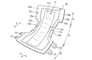
- FIG. 1 is a schematic perspective view of a urine collecting pad, which is a wearing article with a sensor according to a preferred embodiment of the present invention, in a state of being combined with a disposable diaper.
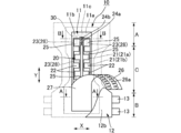
- FIG. 2 is a back view of the urine collection pad attached to the urine collection pad in a state where a part of the covering sheet covering the urine collection sensor is peeled off, as viewed from the non-skin facing surface side.
- 3A is an enlarged schematic cross-sectional view taken along the line AA in FIG. 2 for explaining the urine collecting pad to which the urine sensor and the covering sheet are attached
- FIG. 3B is a cross-sectional view taken along the line B-- in FIG. 4 is an enlarged schematic cross-sectional view along B.
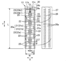
- FIG. 4 illustrates a urine sensor disposed on the urine collection pad and a cover sheet that is attached to cover the urine sensor. It is a back view.
- FIGS. 5A and 5B are enlarged plan views illustrating the form of the printed electrodes.
- FIG. 6 is a block diagram of a data collection unit that detects and collects impedance changes.
- FIGS. 7A to 7E are schematic plan views for explaining the process of attaching the urination sensor to the urine collection pad.
- FIG. 8 shows urination management for detecting the presence / absence of urination of the wearer or measuring the amount of urination based on data transmitted from the data collection unit of the wearing article with sensor according to a preferred embodiment of the present invention. It is a block diagram of an apparatus.
- FIG. 9 is a back view illustrating another form of the urine absorbing pad.
- FIG. 10 is an enlarged schematic cross-sectional view taken along the line CC of FIG.
- the present invention prevents the sheet from contracting when the conductive ink is dried, thereby effectively suppressing variation in detection of the amount of urination by the urine sensor and facilitating the urination sensor using the conductive ink. It is related with the wearing article with a sensor which can be provided in. The present invention also relates to a wearing article with a sensor that can detect the amount of urination with high accuracy without impairing air permeability.
- the present invention is a wearing article with a sensor in which a urination sensor for detecting urination is attached to the outer surface of one of a plurality of sheets constituting the wearing article.
- the urination sensor includes a printing substrate formed of a resin film, and a plurality of planar printing electrodes that form a sensor element using conductive ink applied to the surface of the printing substrate. In addition, a portion where the printing substrate does not exist is provided between the plurality of planar printing electrodes.
- the urination sensor is covered with a covering sheet in which a pressure-sensitive adhesive is applied to a nonwoven fabric, including a portion where the printing substrate is not present, and the single sheet is interposed through the pressure-sensitive adhesive applied to the covering sheet.
- the printing substrate is bonded to the one sheet so that the surface of the printing plate and the printing electrode face each other.
- the one sheet is a base material having poor liquid permeability and electrical insulation.
- the printing substrate is a substrate having electrical insulation.
- the plurality of planar printing electrodes are covered with the one sheet and the printing substrate. Due to the presence of the non-applied part on the pressure-sensitive adhesive-coated surface of the covering sheet, the part where the printing substrate does not exist forms a ventilation opening that retains the ventilation function by the non-coated part.
- a wearing article 10 with a sensor according to a preferred embodiment of the present invention shown in FIG. 1 is a disposable diaper (diaper) in which a urine sensor 20 is attached to a urine collecting pad 11 which is an absorbent article having liquid absorbency, for example. Used in combination with (main body) 12.
- the urine collecting pad 11 is configured to include a vertically long absorbent body 11c (see FIGS. 3A and 3B) as shown in FIG.
- one sheet of the plurality of sheets constituting the wearing article with sensor 10 is the outer side of the urine collecting pad 11 opposite to the skin-facing surface side, which is the side that touches the wearer's skin.
- the back sheet 11b is disposed on the non-skin facing surface side, and the urine sensor 20 is attached to the outer surface thereof.
- the urination sensor 20 includes a sensor element formed by applying a conductive ink to the printing substrate 22 and using a plurality of planar printing electrodes 21 (see FIGS. 2 and 3A).
- the urination sensor 20 can detect the spread of urination absorbed by the urine collecting pad 11 based on the impedance change between the plurality of planar printed electrodes 21.
- the conductive ink is applied to the printing substrate 22 to prevent the back sheet 11b from contracting due to drying of the applied conductive ink when the printed electrode 21 is formed.
- the urination sensor 20 using the urine can be easily and efficiently provided on the urine collection pad 11.
- the urination sensor 20 which detects urination on the back sheet 11b of the urine picking pad 11 as one sheet
- the urine removing pad 11 to which 20 is attached and the disposable diaper 12 which is an outer are combined to form an integrated article.
- the urination sensor 20 is a sensor that includes, for example, a printing substrate 22 formed of an electrically insulating polyethylene terephthalate film and a conductive ink applied to the surface of the printing substrate 22. It includes a plurality of planar printing electrodes 21 that form elements.
- the urination sensor 20 is provided with a portion where the printing substrate 22 does not exist between the plurality of planar printing electrodes 21, and the adhesive 26 is applied to the nonwoven fabric including the portion where the printing substrate 22 does not exist.
- the covering sheet 27 is covered. Through the adhesive 26 applied to the covering sheet 27, the surface of the back sheet 11b and the printed electrode 21 are pasted so as to face each other.
- the urine sensor 20 is covered with a covering sheet 27 made of a nonwoven fabric to which an adhesive 26 is applied (see FIGS. 2 and 4), and the adhesive 26 applied to the covering sheet 27 is applied.
- the printing substrate 22 is attached to the back sheet 11b so that the surface of the back sheet 11b and the print electrode 21 face each other.
- the adhesive 26 is applied to the surface of the covering sheet 27 in, for example, a spiral application pattern (see FIGS. 2 and 4). Thereby, on the surface of the covering sheet 27, a non-application part 26a is formed in a gap part or an outer peripheral part of the adhesive 26 applied in a spiral shape.
- the back sheet 11b which is a single sheet, is a base material having poor liquid permeability and electrical insulation, and the printing base material 22 is a base material having electrical insulation.
- the plurality of planar printing electrodes 21 are preferably covered with a back sheet 11b and a printing substrate 22 together with a conductor portion 23 described later.
- the non-applied portion 26a is present on the surface of the cover sheet 27 where the adhesive 26 is applied, so that the portion where the printing substrate 22 does not exist forms a ventilation opening 25 that retains the ventilation function by the non-applied portion 26a. is doing.
- an auxiliary side sheet (not shown) for forming a three-dimensional gather (not shown) can be provided on the surface side of the urine collecting pad 11.
- the plurality of planar print electrodes 21 are preferably connected via a conductor portion 23.
- the conductive ink is preferably an ink in which metal powder such as silver powder is blended as a conductive substance.
- the conducting wire portion 23 is composed of a printed conductive layer 28 (see FIGS. 3A and 3B) made of conductive ink and applied to the surface of the printing substrate 22.
- a diaper main body (disposable diaper) 12 used in combination with a urine removing pad 11 to which a urination sensor 20 is attached is a disposable diaper described in JP-A-2015-119784 as shown in FIG. It has the same configuration.
- a urine collecting pad 11 as an inner and a diaper main body (disposable diaper) 12 as an outer are combined.
- the diaper main body 12 includes a main body surface sheet 12a in which the urine absorbing pad 11 is mounted on the inner skin facing surface side, a main body back sheet 12b disposed on the most non-skin facing surface side, and both the sheets 12a and 12b. And a main body absorber 12c disposed between the two.
- leg part elastic body (not shown) for leg gather formation is distribute
- Leg gathers 12d are formed by contraction of the body leg elastic members (not shown).
- An auxiliary side sheet (not shown) for forming a three-dimensional gather (not shown), for example, may be further provided on the surface side of the main body surface sheet 12a.
- the main body absorbent body 12c of the diaper main body 12 has a larger planar shape than, for example, the urine collecting pad 11 that is mounted on the skin facing surface (inner side) of the diaper main body 12, and Each of the both side edges and the left and right side edges of the back region B extends outward in the width direction X from the left and right side edges of the crotch region C.
- the left and right side edges of the crotch region C are curved in an arc shape inward in the width direction X, and the central portion in the longitudinal direction Y is constricted inward as a whole.
- the main body absorbent body 12c has an absorbent core formed by holding particles of a water-absorbing polymer in an aggregate of fibers such as pulp fibers, similarly to the absorbent body 11c of the urine absorbing pad 11 described later. It is formed in a state covered with a sheet.
- the main body surface sheet 12a and the main body back sheet 12b extend outward from both side edges along the longitudinal direction Y of the main body absorber 12c and from both end edges along the width direction X, respectively.
- the main body surface sheet 12a and the main body back sheet 12b are joined to each other by an adhesive, heat fusion, or the like at the extending portion extending outward from the peripheral edge of the main body absorber 12c.
- the absorber 12c is provided in a sandwiched and fixed state.
- the diaper main body 12 formed as described above has a shape in which the central portion in the longitudinal direction Y is inwardly bound as a whole.
- the diaper main body 12 is a so-called unfolded diaper, and two pairs of fastening tapes 13 are provided on the left and right side edges of the back region B. Further, a landing tape (not shown) for fastening the fastening tape 13 is provided on the outer surface (non-skin facing surface) of the ventral region A of the diaper main body 12.
- the outer combined with the urine removing pad 11 as the inner may be a disposable diaper, cloth pants, rehabilitation pants or the like.
- the wearing article 10 with a sensor may be a disposable diaper with a sensor (tape stop, rehabilitation pants) or the like in addition to the urine absorbing pad with a sensor sheet.
- the urine removing pad 11 that is attached to the skin facing surface (inside) of the diaper main body 12 includes a liquid-permeable surface sheet 11 a disposed on the skin facing surface side and a non-permeable surface sheet 11 a. It is configured to include a liquid-impermeable back sheet 11b disposed on the skin facing surface side and an absorbent body 11c disposed between these sheets 11a and 11b (FIGS. 3A and 3B). reference).
- the top sheet 11a, the back sheet 11b, and the absorbent body 11c of the urine absorbing pad 11 have a rectangular shape that is long in the longitudinal direction Y of the wearing article 10 with the sensor.
- the top sheet 11a and the back sheet 11b are provided to extend outward from both side edge portions along the longitudinal direction Y of the absorbent body 11c and both end edge portions along the width direction X, respectively, and the main body of the diaper main body 12 Similar to the partial absorber 12c, the central portion in the longitudinal direction Y has a shape that is bound inward.
- the top sheet 11a and the back sheet 11b are joined to each other by an adhesive, heat fusion, or the like, directly or via a side sheet or the like, at an extended portion extending outward from the periphery of the absorber 11c.
- the absorbent body 11c is sandwiched and fixed inside. As shown in FIGS. 3 (a) and 3 (b), the absorbent body 11c has an absorbent core 11d in which water-absorbing polymer particles are held in an aggregate of fibers such as pulp fibers. It is formed in a state of being covered with a wrap sheet 11e.
- the urination sensor 20 for detecting urination is preferably provided on the back sheet 11b of the urine collecting pad 11 as one of the plurality of sheets constituting the wearing article 10. It is attached. That is, in the present embodiment, the urination sensor 20 includes a plurality of sensor elements 20a formed by a plurality of planar print electrodes 21 made of conductive ink applied to the surface of the printing substrate 22, as will be described later. Yes.
- the plurality of planar printed electrodes 21 are a plurality of positive electrodes 21a and a plurality of negative electrodes 21b, and a plurality of positive electrodes 21a and a plurality of negative electrodes 21b include a plurality of positive electrodes 21a and a plurality of negative electrodes 21b.
- the sensor element 20a is configured.
- the urination sensor 20 detects a change in impedance of each sensor element 20a using a sensor element 20a including a positive electrode 21a and a negative electrode 21b.
- the wearing article with sensor 10 Based on the detected impedance change, the wearing article with sensor 10 detects the presence or absence of urination by the wearer, or the amount of urine absorbed and urination from the spread of urine absorbed by the urine collection pad 11 during urination. The amount and the like can be measured or estimated.
- the plurality of planar printed electrodes 21 are arranged at eight locations at intervals along the longitudinal direction Y of the urine collecting pad 11.
- the eight printed electrodes 21 (electrode arrays) arranged at intervals along the longitudinal direction Y have a configuration in which positive electrodes 21a and negative electrodes 21b are alternately arranged at intervals.
- the positive electrode 21a and the negative electrode 21b that are adjacent in the direction Y constitute the sensor element 20a described above.
- a portion where the printing base material 22 does not exist is provided in a gap portion between the positive electrode 21a and the negative electrode 21b.
- print electrodes 21 (electrode rows) arranged at intervals along the longitudinal direction Y are arranged in two rows at a predetermined interval in the width direction X, and 16 in total.
- the printed electrodes 21 are uniformly distributed in the width direction X and the longitudinal direction Y.
- the two print electrodes 21 adjacent in the width direction X may be arranged in a relationship of a negative electrode with respect to the positive electrode and a positive electrode with respect to the negative electrode.
- the positive electrode and the negative electrode are arranged in a negative electrode relationship.
- the number of the printed electrodes 21 to be arranged is preferably 6 to 12 in the longitudinal direction Y of the urine collecting pad 11.
- the plurality of planar printed electrodes 21 are arranged in two rows along the longitudinal direction Y of the urine collecting pad 11, and eight in each electrode row, a total of 16 are arranged. (See FIG. 4).
- the eight printed electrodes 21 arranged in each electrode row four positive electrodes 21 a and negative electrodes 21 b that are alternately arranged in the longitudinal direction Y are connected to each other by a conductor portion 23.
- the four positive electrodes 21a of each electrode row are connected to a conductor portion 23a that is arranged to extend linearly along the longitudinal direction Y inside the width direction X (near the center line CL).
- One end portion of the conducting wire portion 23a is connected to a terminal portion 24a provided at an end portion in the longitudinal direction Y of the urine collecting pad 11.
- the four negative electrodes 21b of each electrode row are connected to the conductor portions 23b1 that are arranged to extend linearly in the longitudinal direction Y on both sides along the longitudinal direction Y of the urine collecting pad 11.
- one end portion in the longitudinal direction Y of the conducting wire portion 23b1 is connected to one end portion of the conducting wire portion 23b2 arranged to extend linearly in the width direction X.
- the other end portion of the conducting wire portion 23b2 is connected to a terminal portion 24b provided at an end portion in the longitudinal direction Y of the urine collecting pad 11.
- the conducting wire portion 23a is configured to be disposed inside the urination sensor 20 (close to the center line CL) when the urination sensor 20 is viewed in plan.
- the lead wire portion 23b1 is configured to be disposed outside the plurality of positive electrodes 21a so as to surround the plurality of positive electrodes 21a in a plan view of the urine sensor 20.
- the plurality of negative electrodes 21b are grounded via the terminal portion 24b. By grounding the plurality of negative electrodes 21b arranged on the outside, the urination sensor 20 can reduce the intrusion of external noise and improve the measurement accuracy.
- the plurality of planar printed electrodes 21 constituting the urination sensor 20 are formed in a planar shape by applying conductive ink to the surface of the printing substrate 22 as will be described later.
- Each printed electrode 21 has the same rectangular shape as shown in FIG. That is, the positive electrode 21a and the negative electrode 21b are formed in the same rectangular shape.
- the ratio of the length L1 ((L1 / L) ⁇ 100) is preferably about 0.19 to 22%, and the length L1 of the printing substrate 22 with respect to the length W in the width direction X is the same.
- the ratio ((W1 / W) ⁇ 100) of the length W1 in the X direction (same as the width direction X of the urine removing pad 11 (see FIG. 4)) of the printed electrode 21 (positive electrode 21a and negative electrode 21b) is 3 It is preferable to be about 93%.
- the length L in the longitudinal direction Y of the printing substrate 22 is preferably about 380 to 532 mm, and the length in the Y direction of each printing electrode 21 (positive electrode 21a and negative electrode 21b).
- L1 is preferably about 1 to 100 mm.
- the length W in the width direction X of the printing substrate 22 is preferably about 78 to 162 mm, and the length W1 in the X direction of each printing electrode 21 (the positive electrode 21a and the negative electrode 21b) is It is preferably about 3 to 150 mm.
- the area of each printed electrode 21 (positive electrode 21a and negative electrode 21b) is preferably about 3 to 1500 mm 2.
- the ratio ((L2 / L) ⁇ 100) of the separation distance L2 (see FIG. 4) in the longitudinal direction Y between the positive electrode 21a and the negative electrode 21b with respect to the length L in the longitudinal direction Y of the printing substrate 22 is It is preferably about 0.18 to 6.6%, and in the width direction X between the adjacent print electrodes 21 (each electrode row) in the width direction X with respect to the length W in the width direction X of the printing substrate 22.
- the ratio ((W2 / W) ⁇ 100) of the separation distance (predetermined interval) W2 (see FIG. 4) is preferably about 6 to 20%.
- the separation distance W2 (see FIG. 4) in the X direction of each row is preferably about 5 to 15 mm.
- the planar printed electrode 21 is formed by applying conductive ink on the surface of the printing base material 22 so as to have a non-coated portion, for example, in a lattice shape. It is possible to reduce the cost by reducing the amount of ink used.
- the shape, size, mutual arrangement position, and the like of the planar printing electrode 21 are not limited to those of the present embodiment, and can be appropriately designed.
- the conductor part 23 (conductor part 23a, 23b1, 23b2) for connecting each electrode group by the four planar printing electrodes 21 to the terminal part 24 (terminal part 24a, 24b). Is formed by a printed conductive layer 28 (see FIGS. 3A and 3B) made of conductive ink applied to the surface of the printing substrate 22 in the same manner as the printed electrode 21.
- the conductive wire portion 23 (conductive wire portions 23a, 23b1, 23b2) is formed by the printed conductive layer 28 made of conductive ink so that the printed electrode 21 is connected to the terminal portion 24 (terminal portions 24a, 24b).
- the metal snap 24 is composed of a female hook 241 and a male hook 242, and between the female hook 241 and the male hook 242 in the thickness direction Z.
- the female hook 241 and the male hook 242 are fitted with the covering sheet 27, the conductive wire portion 23, and the printing base material 22 interposed therebetween.
- a metal connector, a fastener, a hook-and-loop fastener (such as Velcro (registered trademark)), a screw, a hook, a biting fastener, or the like may be used.
- the planar printed electrode 21 and the conductive wire portion 23 (printed conductive layer 28) constituting the urination sensor 20 are provided with a predetermined arrangement shape (FIG. 6 ( It is formed by applying so as to obtain a).
- the printing substrate 22 is an electrically insulating resin film having physical properties that do not shrink when the applied conductive ink is dried, and preferably a polyethylene terephthalate film having a thickness of, for example, about 35 to 75 ⁇ m. It is formed using.
- the printing substrate 22 has physical properties that do not shrink when the applied conductive ink is dried, and preferably uses a material having a melting point of 200 ° C. or higher, such as polyethylene terephthalate or polyimide, as an electrically insulating resin film. Can be formed.
- the printing substrate may have poor liquid permeability. “Liquid permeability” refers to the property that liquid such as water does not pass but gas such as water vapor passes.
- the conductive ink applied to the printing substrate 22 may be, for example, a mixture of a dispersant, a binder, a resin, a curing agent, or the like mixed with, for example, carbon powder as a conductive substance, or silver. What mix
- the conductive ink When the conductive ink is applied to the printing substrate 22 to form the conductor portion 23 by the planar print electrode 21 or the print conductive layer 28, the conductive ink may be printed (applied) only once. However, from the viewpoint of increasing the sensitivity for detecting urination, it may be formed by printing (applying) a plurality of times. The number of times of overprinting is preferably 1 to 10 times.
- a known method such as inkjet printing, rotary printing, flexographic printing, screen printing, gravure printing, or the like can be employed.
- the printing base material 22 is lacking because substantially the entire region other than the printing electrode 21 and the conductor portion 23 is removed in a cutting step (see FIG. 6B) described later.
- This removed and chipped portion specifically, the region between the positive electrode 21a and the negative electrode 21b forming the sensor element 20a, that is, other than the printed electrode 21 and the conductor portion 23 where the printing base material 22 is not present.
- the portion forms a ventilation opening 25 that retains a ventilation function by a non-application portion 26a of the adhesive 26 described later (see FIG. 4).
- the back surface sheet 11b of the urine removing pad 11 to which the urine sensor 20 is attached is formed by the ventilation opening 25 formed by cutting the polyethylene terephthalate film. It is possible to suppress a decrease in air permeability.
- the printing electrode 21 and the conducting wire part 23 cut the part to which electroconductive ink is not applied, or the printing base material 22 by a resin film. After the conductive ink is printed in advance on the entire surface, the printing base material 22 on which the conductive ink is printed may be cut into a desired print pattern.
- the ventilation opening 25 used as a ventilation area should just be substantially enclosed by the edge part, and the surrounding edge part does not need to be continuing.
- the ventilation opening 25 is preferably formed in an area of 10% or more of the area surrounded by connecting the outer shapes of the printing base material 22, and more preferably in an area of 25% or more. preferable. Further, the ventilation opening 25 exists between two electrodes (positive electrode 21a and negative electrode 21b) adjacent in the longitudinal direction Y constituting the urination sensor 20. Specifically, it is preferable from the viewpoint of maintaining the air permeability of the back sheet 11b that it is provided in a region substantially surrounded by the positive electrode 21a, the negative electrode 21b, and the conductor portions 23a, 23b1, 23b2.
- the urination sensor 20 having a plurality of planar printed electrodes 21 and a printed conductive layer 28 formed by applying conductive ink to the printing substrate 22 is a covering sheet 27 made of a non-woven fabric having air permeability. Is attached to the surface of the back sheet 11b of the urine collecting pad 11.
- the urination sensor 20 is covered at a portion where the printing substrate 22 is not present, in other words, at a portion other than the printing substrate 22 in the urination sensor 20.
- a ventilation opening 25 is formed in which the ventilation function is maintained by passing through the non-application part 26 a of the adhesive 26 in the sheet 27.
- the printed electrode 21 and the printed conductive layer 28 are printed using a covering sheet 27 in a state where they are adhered to the surface of the back sheet 11b of the urine absorbing pad 11 (the surface opposite to the skin facing surface). It is attached to the back sheet 11b together with the material 22.
- the adhesive 26 is applied to the cover sheet 27 on the surface in contact with the back sheet 11b. That is, the adhesive 26 is applied to the covering sheet 27 on the inner surface on the skin facing surface side.
- the adhesive 26 adheres to the back surface sheet 11b of the urine removing pad 11 outside the ventilation opening 25 formed at the portion lacking after the printing base material 22 is removed or the outer peripheral portion of the printing base material 22.
- the covering sheet 27 is attached so as to cover the urine sensor 20 in a state where the urine sensor 20 is sandwiched between the cover sheet 27 and the back sheet 11b.
- the urination sensor 20 including the printing base material 22, the plurality of planar printing electrodes 21 made of conductive ink, the conductive wire portion 23 including the printed conductive layer 28 made of conductive ink, and the terminal portion 24 is provided.
- the urine collecting pad 11 is disposed so as to overlap the back surface sheet 11b along the back surface sheet 11b of the urine picking pad 11 with the printed electrode 21 in close contact with the surface of the back surface sheet 11b of the urine collecting pad 11.
- the back sheet 11b, the top sheet 11a, and the absorbent body 11c of the urine absorbing pad 11 those conventionally used for absorbent articles such as disposable diapers, urine absorbing pads, sanitary napkins and the like are particularly limited.
- the back sheet 11b for example, a liquid-impervious insulating sheet (such as a moisture-permeable resin film) used for absorbent articles, or a nonwoven fabric (for example, an air-through nonwoven fabric or a spunbond) produced by various manufacturing methods is used for the insulating sheet.
- a laminated sheet obtained by laminating a nonwoven fabric, a spunlace nonwoven fabric, a needle punch nonwoven fabric, or the like can be used.
- the liquid permeability is a property that does not allow liquid such as water to pass but allows gas such as water vapor to pass.
- a hydrophilic and liquid-permeable nonwoven fabric or a three-dimensional aperture film can be used.
- an absorptive core which constitutes absorber 11c for example, an aggregate of fibers such as pulp fibers in which absorbent polymer particles are held can be used.
- a core wrap sheet which constitutes absorber 11c for example, A hydrophilic sheet such as a core wrap sheet made of a water-permeable thin paper (tissue paper) or a water-permeable nonwoven fabric can be used.
- the thing of the material conventionally used for the wearing article can be used as a nonwoven fabric which comprises the coating sheet 27, Specifically, nonwoven fabrics, such as a spun bond, a spun lace, and an air through, are used. Can be used.
- spunbonded nonwoven fabric the basis weight, in view of workability such as not tear during processing, 5 g / m 2 or more, more preferably 10 g / m 2 or more, thickness and feel, cost In view of the above, 100 g / m 2 or less is preferable, and 80 g / m 2 or less is more preferable.
- the basis weight of the spunbonded nonwoven fabric is preferably 5 g / m 2 or more and 100 g / m 2 or less, more preferably 10 g / m 2 or more and 100 g / m 2 or less, and more preferably 5 g / m 2 or more and 80 g / m 2 or less. 10 g / m 2 or more and 80 g / m 2 or less is most preferable.
- the nonwoven fabric 27 constituting the covering sheet 27 has air permeability, and the air permeability is preferably 10 m / kPa ⁇ s or more, more preferably 20 m / kPa ⁇ s or more from the viewpoint of moisture permeability.
- the air permeability of the nonwoven fabric 27 is preferably 10 m / kPa ⁇ s or more and 1500 m / kPa ⁇ s or less, more preferably 20 m / kPa ⁇ s or more and 1500 m / kPa ⁇ s or less, and more preferably 10 m / kPa ⁇ s or more and 800 m / kPa ⁇ s.
- the air permeability is obtained as the reciprocal of the air resistance measured by an AUTOMATIC AIR-PERMEABILITY TESTER KES-F8-AP1 (air permeability tester) manufactured by Kato Tech. In the case of a material with low air permeability, it can also be determined from the measured value of the galley densometer.
- an adhesive for skin and underwear can be preferably used.
- the pressure-sensitive adhesive for example, acrylic or rubber-based ones can be used, and preferably a rubber-based one can be used.
- a well-known coating pattern such as a spiral shape, a summit shape, an omega shape, a curtain shape, or a stripe shape can be adopted as the coating pattern in which the non-coated portion 26a of the adhesive 26 is present.
- the printing substrate The ventilation opening 25 of 22 is ventilated through at least the non-application portion 26a, thereby suppressing a decrease in the air permeability of the back sheet 11b of the urine collecting pad 11 to which the urine sensor 20 is attached.
- the urine collection pad 11 applies a voltage that periodically changes with time to the plurality of positive electrodes 21 a and the plurality of negative electrodes 21 b (the plurality of sensor elements 20 a) of the urination sensor 20.
- the data collection unit 30 is configured to collect a change in impedance by applying a voltage having an AC component.
- the data collection unit 30 collects a change in impedance by applying a rectangular wave voltage having a predetermined frequency.
- the data collection unit 30 includes an impedance detection unit 31 that detects an impedance change, a data logger 32 that stores impedance change data detected by the impedance detection unit 31, and a timer 33 that outputs time data. And an acceleration sensor 34 for detecting the displacement of the posture of the wearer.
- the impedance detection unit 31 applies a rectangular wave voltage of about 300 to 1500 KHz in the range of 0 to 5 V to the entire circuit of the plurality of sensor elements 20 a of the urination sensor 20 attached to the urine collection pad 11, The change in impedance of the sensor element 20a is detected. Specifically, as shown in FIG. 6, the impedance detection unit 31 detects an impedance change of the whole of the plurality of sensor elements 20a using an oscillator 31a that oscillates a predetermined frequency signal and the frequency signal from the oscillator 31a. And an impedance change voltage conversion unit 31c that converts the impedance change detected by the impedance change detection circuit 31b into voltage change data.
- the impedance change detection circuit 31b is realized, for example, by configuring a bridge circuit with the impedance Zx of the sensor element 20a of the urination sensor 20 and impedance elements Z1 to Z3 whose impedances are known.
- a predetermined frequency signal for example, a rectangular wave of 600 kHz at 0 to 1.8 V
- the oscillator 31a for example, a rectangular wave of 600 kHz at 0 to 1.8 V
- the impedance change voltage conversion unit 31c detects a differential voltage between the divided voltage by the impedance elements Z1 and Z2 and the divided voltage by the impedance Zx of the impedance element Z3 and the sensor element 20a, and according to the magnitude of the impedance Zx
- the voltage data of the measured voltage value is output to the data logger 32.
- the acceleration sensor 34 is preferably a triaxial acceleration sensor.
- the acceleration sensor 34 represents voltage data corresponding to the inclination of the data collection unit 30 of acceleration in the X-axis direction, the Y-axis direction, and the Z-axis direction due to the displacement of the posture of the wearer wearing the wearing article 10 with the sensor. It is detected and output to the data logger 32 together with the time data output from the timer 33.
- the voltage data output to the data logger 32 (voltage data corresponding to the magnitude of the impedance Zx and voltage data corresponding to the inclination of the data collecting unit 30) is output every unit time together with the time data output from the timer 33. And preferably stored.
- the output unit time is preferably 0.1 to 60 seconds, more preferably 0.1 to 10 seconds.
- the data logger 32 is a device that stores data acquired from the impedance detection unit 31 and the acceleration sensor 34. When the data logger 32 detects the presence or absence of the urination of the wearer or measures the amount of urination or the like in response to a request from the urine management device 40 described later or when it is detected that it is connected to the urine management device 40 The stored data is transmitted to the urination management device 40 wirelessly or by wire.
- the data logger 32 includes voltage data of a voltage value corresponding to the magnitude of the impedance Zx, and the inclination of the data collection unit 30 in the X-axis direction, the Y-axis direction, and the Z-axis direction due to the displacement of the wearer's posture. Is transmitted to the urination management device 40 wirelessly together with the respective time data.
- the data collection unit 30 has a power supply (battery in this embodiment) for generating a voltage to be applied to the printing electrode 21 (the positive electrode 21a and the negative electrode 21b).
- the data collection unit 30 is attached to the urination sensor 20 so as to cover the terminal units 24a and 24b.
- the data collection unit 30 is connected to the positive electrode via the terminal unit 24a.
- a voltage is applied to 21a.
- the data collection unit 30 is provided with two hooks (not shown) that can be engaged with the terminal units 24a and 24b, so that the position of the data collection unit 30 with respect to the urination sensor 20 is fixed. Yes.
- the acceleration sensor 34 can easily detect the posture of the wearer.
- the urine collection pad 11 to which the urination sensor 20 and the data collection unit 30 having the above-described configuration are attached can be easily and efficiently formed according to the following manufacturing steps shown in FIGS. 7 (a) to 7 (e). . That is, in order to form the urine removing pad 11 to which the urine sensor 20 is attached, first, in the ink application process, the conductive ink is applied to the surface of the printing substrate 22 with the 16 planar printing electrodes 21 and It is applied so as to have a predetermined arrangement and shape including each printed electrode 21 and a plurality of printed conductive layers 28 connecting the terminal portions 24a and 24b (see FIG. 7A).
- the applied conductive ink is dried, preferably in the cutting step, preferably substantially the whole or at least a part of the area other than the coated planar printing electrode 21 and the printed conductive layer 28 is cut on the printing substrate 22. By removing them, the ventilation openings 25 are formed (see FIG. 7B).
- the covering sheet 22 is covered by covering the printing substrate 22 provided with the planar printing electrode 21 and the printing conductive layer 28 via the adhesive 26 applied to the covering sheet 27. 27 is attached.
- the terminal portion 24a of the positive electrode 21a and the terminal portion 24b of the negative electrode 21b are attached at predetermined positions connected to the conductor portion 23 by the printed conductive layer 28 (see FIG. 7D).
- the covering sheet 27 is applied to the back sheet 11b of the urine collecting pad 11 through the applied adhesive 26 in the portion extending outside the urination sensor 20 and the portion of the ventilation opening 25 of the printing base material 22.
- the urination sensor 20 covered with the covering sheet 27 is attached to the urine collecting pad 11 together with the covering sheet 27 (see FIG. 7E).
- the covering sheet 27 is attached to the back sheet 11b easily and accurately by bonding the covering sheet 27 in accordance with a print (not shown) indicating the attaching position of the covering sheet 27 provided on the back sheet 11b. Can be pasted.
- the data collection part 30 is fixed via the terminal part 24a of the positive electrode 21a, and the terminal part 24b of the negative electrode 21b.
- the urination sensor 20 is attached to the urine collection pad 11 so as to be sandwiched between the covering sheet 27 and the back sheet 11b. That is, a plurality of sheet-like positive electrodes 21a and sheet-like negative electrodes 21b (a plurality of sensor elements 20a) are formed by both the back sheet 11b which is an insulating sheet and the printing substrate 22 which is an insulating substrate (insulating film).
- the urine collection pad 11 is formed so as to be sandwiched.
- the urine collecting pad 11 When the urine collecting pad 11 to which the urination sensor 20 is attached is formed, the urine collecting pad 11 is mounted on the skin facing surface (inside) of the diaper main body 12 as described above.
- the diaper main body 12 may be underwear such as other absorbent articles, briefs, shorts, girdles, paper pants, rehabilitation pants, in addition to disposable diapers.
- FIG. 8 the presence or absence of urination of the wearer wearing the wearing article with sensor 10 is detected based on data transmitted from the data collection unit 30 of the wearing article with sensor 10 according to a preferred embodiment of the present invention.
- a block diagram of the urination management device 40 that measures the amount of urination and the like is shown.
- the urination management device 40 transmits the voltage data of the voltage value according to the magnitude of the impedance Zx transmitted from the data collection unit 30, and the X-axis direction, the Y-axis direction, and the Z-axis direction due to the displacement of the posture of the wearer. Based on the voltage data corresponding to the inclination of the data collection unit 30, it is possible to detect the presence or absence of urination of the wearer and to measure the amount of urination and the like.
- the urination management apparatus 40 is, for example, a computer and includes a CPU, a ROM, a RAM, an HDD, and the like, and as illustrated in FIG. An estimation unit 43 is included.
- the data acquisition unit 41 can be logically connected to the data collection unit 30 of the wearing article with sensor 10 by wire or wirelessly.
- data of the data collection unit 30 is obtained.
- Data output from the logger 32 is received.
- the data acquisition unit 41 includes the voltage data of the voltage value according to the magnitude of the impedance Zx output from the data collection unit 30, and the X-axis direction, the Y-axis direction, and the displacement of the wearer's posture. Voltage data corresponding to the inclination of the data collecting unit 30 in the Z-axis direction is received.
- the posture determination unit 42 is data regarding the wearer's posture by the acceleration sensor 34 received by the data acquisition unit 41 (the inclination of the data collection unit 30 in the X-axis direction, the Y-axis direction, and the Z-axis direction due to the displacement of the wearer's posture). For example, the wearer determines which of the postures such as prone, face-up, face-up, and sitting.
- the urination amount estimation unit 43 is input to the data acquisition unit 41, the data relating to the impedance change output from each sensor element 20a of the urination sensor 20 (voltage data of a voltage value corresponding to the magnitude of the impedance Zx), and posture determination The amount of urination is estimated from the posture of the wearer determined by the unit 42.
- the urine output estimating unit 43 detects the spread of urine based on the voltage data of the voltage value corresponding to the magnitude of the impedance Zx output from each sensor element 20a, and the spread of the urine and the wearer The amount of urination is estimated from the posture.
- the urination amount estimation unit 43 stores in advance the voltage value of each sensor element 20a in a state where there is no urine, and determines that there is urination when the voltage is lower than in the state where there is no urine. . Then, the spread of urine is determined based on the amount of change in data according to the impedance change when it is determined that urination has occurred. Furthermore, the urine output estimation unit 43 selects a urine output calculation formula corresponding to the posture of the wearer determined by the posture determination unit 42 from the determined spread of urine and a plurality of urine output calculation formulas stored in the RAM in advance. Then, the urination amount at the time of measurement is estimated using the corresponding urination amount calculation formula. In this way, the urination management device 40 can estimate the amount of urination of the wearer wearing the wearing article 10 with the sensor.
- the urination amount estimation in the urination amount estimation unit 43 is performed in a stepwise manner, for example, by using a relative amount such as small or large with respect to the total absorption capacity of the wearing article with sensor 10 instead of the numerical value of the urination amount. It may be output.
- coating conductive ink to the printing base material 22 to a back surface sheet was employ
- the conductive ink is dried, it is possible to prevent the sheet from contracting, thereby effectively suppressing variation in detection of the urination amount by the urination sensor 20, and using the conductive ink.
- the urination sensor 20 can be easily provided.
- the urination sensor 20 has a plurality of planar prints that form the sensor element 20a by the printing base 22 made of a resin film and the conductive ink applied to the surface of the printing base 22.
- the electrode 21 (the positive electrode 21a and the negative electrode 21b) is comprised.
- the conductive ink is not directly applied to one sheet among a plurality of sheets constituting the wearing article 10 such as the back sheet 11b of the urine picking pad 11, but is applied to the printing substrate 22.
- the planar printed electrode 21 is formed. And the formed printed electrode 21 is provided in the wearing article 10 by affixing on the back surface sheet 11b with the printing base material 22, for example.
- the printing base material 22 made of a resin film such as a polyethylene terephthalate film to which the conductive ink is applied preferably has physical properties that do not shrink when the applied conductive ink is dried.
- the back sheet 11b is not contracted when the conductive ink is dried.
- the urination sensor 20 in which the printed electrode 21 is formed using the conductive ink can be easily and efficiently formed by one sheet among the plurality of sheets constituting the wearing article 10 according to the manufacturing process described above, for example. It can be provided on a certain back sheet 11b.
- the printing base material 22 made of a resin film such as a polyethylene terephthalate film to which the conductive ink is applied has physical properties that are difficult to stretch as compared with the nonwoven fabric. Therefore, by attaching and using the urination sensor 20 provided with a plurality of planar printing electrodes 21 by applying conductive ink to the printing substrate 22 to the wearing article 10, for example, the planar positive electrode 21a and the surface
- the distance L2 (FIG. 4) between the negative electrode 21b and the negative electrode 21b can be kept constant, thereby making it possible to detect a stable change in impedance and to detect the amount of urination in the urine sensor 20. It is possible to effectively suppress the occurrence of variations.
- the urination sensor 20 which formed the planar printed electrode 21 by apply
- a rectangular wave voltage of a predetermined frequency is preferably applied to the planar printed electrode 21 of the urination sensor 20, and the impedance change between the planar positive electrode 21a and the planar negative electrode 21b.
- the printing substrate 22 made of a resin film such as a polyethylene terephthalate film to which the conductive ink is applied has electrical insulation. Therefore, the front side and the back side of the printed electrode 21 are covered by sandwiching the planar printed electrode 21 by the printing base material 22 having electrical insulation and the back sheet 11b having electrical insulation.
- the planar printed electrode 21 can be electrically insulated from the outside of the urination sensor 20 with respect to the direct current. By making the printed electrode 21 in an insulating state with respect to a direct current, for example, unlike a worn article having an electrode (sensor) that detects urination by being in direct contact with urine, a change in capacitance between the electrodes is detected.
- the urination sensor 20 is equipped with the ventilation opening part 25 which maintains a ventilation function by the part in which the printing base material 22 does not exist, for example, Even when the printed electrode 21 is electrically insulated from the outside of the urine sensor 20 to detect a change in capacitance between the electrodes, the air permeability of the urine collecting pad 11 to which the urine sensor 20 is attached is not impaired. It becomes possible to detect the amount of urination with high accuracy.
- the printing base material 22 exists between the plurality of planar printing electrodes 21 formed by applying conductive ink to the printing base material 22 constituting the urination sensor 20.
- the part which is not done is provided.
- the urination sensor 20 is covered with a covering sheet 27 in which a pressure-sensitive adhesive 26 is applied to a non-woven fabric, including a portion where these printing base materials 22 are not present, and the pressure-sensitive adhesive 26 applied to the covering sheet 27 is interposed therebetween.
- the printing base material 22 is affixed to the back sheet 11b of the urine absorption pad 11 in a state where the surface of the back sheet 11b and the printing electrode 21 face each other.
- the adhesive 26 in the nonwoven fabric is applied to the part where the printing substrate 22 of the urine sensor 20 does not exist.
- the urination sensor 20 is provided with a ventilation opening 25 that retains a ventilation function in the non-application part 26a where the adhesive 26 is not applied by being covered with the applied part and the non-application part 26a where the adhesive 26 is not present. Forming. As a result, even if the printing electrode 21 of the urination sensor 20 is formed by applying a conductive ink to the printing base material 22 that is not air permeable, the printing base material 22 of the urination sensor 20 does not exist.
- a certain ventilation opening 25 makes it possible to ensure sufficient air permeability for the urine collection pad 11 to which the urine sensor 20 is attached and the wearing article 10 to which the urine collection pad 11 is attached.
- the printed electrode 21 formed on the urine 22 makes it possible to accurately detect the amount of urine discharged from the urine absorbing pad 11 without causing the printed electrode 21 to be deformed due to shrinkage during drying.
- the urine sensor 20 is integrally attached to the back sheet 11b of the urine collecting pad 11 together with the cover sheet 27 through the adhesive 26 applied to the cover sheet 27. Therefore, since it becomes difficult to reuse the urination sensor 20 repeatedly, for example, it is possible to avoid the possibility of infection by bacteria easily by reusing it, and it is possible to use it hygienically.
- FIG. 9 illustrates another form of the urine absorbing pad constituting the wearing article with the sensor.
- the urine collecting pad 11 ′ of the wearing article 10 ′ with sensor shown in FIG. 9 has substantially the same configuration as the urine collecting pad 11 of the above embodiment.
- the printing base material 22 ′ made of a resin film such as a polyethylene terephthalate film to which the conductive ink is applied has electrical insulation. Therefore, the front side and the back side of the printed electrode 21 ′ are covered by sandwiching the planar printed electrode 21 ′ between the printed base material 22 ′ having electrical insulation and the back sheet 11b ′ having electrical insulation. ing.
- the urination sensor 20 ′ is covered with the covering sheet 27 ′ in which the adhesive 26 ′ is applied to the nonwoven fabric, including the portion 25 ′ where the printing base material 22 ′ does not exist, and is applied to the covering sheet 27 ′.
- the printed substrate 22 ′ is attached to the back sheet 11b ′ of the urine collecting pad 11 ′ with the surface of the back sheet 11b ′ and the printed electrode 21 ′ facing each other through the adhesive 26 ′. ing.
- a planar printed electrode 21 ′ arranged to overlap the portion of the urine sensor 20 ′ pasted on the back sheet 11 b ′ of the urine collecting pad 11 ′ via the covering sheet 27.
- a through hole 29 is formed through the printing substrate 22 ′ and the covering sheet 27. That is, in the wearing article 10 ′ of another form shown in FIG. 9, a plurality of through holes 29 penetrating the printing base material 22 ′ and the covering sheet 27 are formed in the portion of the planar printed electrode 21 ′ (inside the surface).
- a plurality of through holes 29 that pass through the printing base material 22 ′ and the covering sheet 27 are provided, and ventilation openings 25 are formed by portions where the printing base material 22 ′ does not exist between the planar printing electrodes 21 ′.
- an additional ventilation opening that retains the ventilation function is formed inside the surface of the planar printed electrode 21'.
- the through holes 29 formed in the planar printed electrode 21 ′ are formed at a plurality of locations with respect to each printed electrode 21 ′. Preferably, it is formed at ⁇ 8 locations. In the present embodiment, five through holes 29 are formed for each printed electrode 21 ′. In addition, the ratio of the total area of the plurality of through holes 29 to the area of each print electrode 21 ′ is preferably about 2 to 74%, and the ratio of the area of each through hole 29 to the area of each print electrode 21 ′ is 2 to 74%. About 9.2% is preferable. In the present embodiment, the plurality of through holes 29 are formed in a substantially circular shape, and the diameter of each through hole 29 is preferably about 2 to 4 mm, and the area of each through hole 29 is preferably about 12 to 29 m 2 .
- the conductor portion 23 ′ is composed of a printed conductive layer 28 ′ made of conductive ink applied to the surface of the printing substrate 22 ′. ing.
- these through holes 29 also function as ventilation openings, so that the printed electrode 21 ′ and the printing substrate It is possible to more effectively improve the air permeability of the urine collecting pad 11 ′ to which the urine sensor 20 ′ is attached by compensating for the decrease in air permeability due to the provision of the 22 ′ and the printed conductive layer 28 ′.
- the urine collecting pad 11 ′ of the wearing article 10 ′ with the sensor shown in FIG. 9 it is connected to a plurality of planar printed electrodes 21 ′ (or a conductor portion connecting these planar printed electrodes 21 ′).
- the terminal portions 24a ′ and 24b ′ are arranged such that the number of terminal portions 24a ′ connected to the positive electrode 21a ′ is different from the number of terminal portions 24b ′ connected to the negative electrode 21b ′. That is, in the urine collection pad 11 ′ shown in FIG. 9, at the end portion in the longitudinal direction Y, for example, the terminal portion 24a ′ of one positive electrode 21a ′ and the terminal portion 24b ′ of two negative electrodes 21b ′. And are provided.
- the data collection unit 30 includes a terminal portion 24a ′ of one positive electrode 21a ′ and a terminal portion 24b ′ of two negative electrodes 21b ′. Three corresponding hooks (not shown) are attached. Since the number of terminal portions 24a ′ connected to the positive electrode 21a ′ is different from the number of terminal portions 24b ′ connected to the negative electrode 21b ′, and their arrangement is rotationally asymmetric, the terminal portion 24a It becomes possible to make the direction of the measuring instrument (the data collecting unit 30 described above) attached to the urine collecting pad 11 ′ through “, 24b” constant.
- the posture of the wearer is detected by the acceleration sensor, the urine distribution in the urine collecting pad 11 is estimated, and the urine amount calculation is performed. It is important to reflect this in In order to correctly detect the posture of the wearer by the acceleration sensor, it is necessary that the direction of the data collection unit 30 as a measuring instrument is constant when attached to the urine collection pad 11 '. Since the number of terminal portions 24a ′ connected to the positive electrode 21a ′ is different from the number of terminal portions 24b ′ connected to the negative electrode 21b ′, the data collecting portion attached to the urine collecting pad 11 ′. Since the attachment direction of 30 is fixed, erroneous detection of the wearer's posture is prevented, and as a result, it is possible to improve calculation accuracy when estimating the amount of urination.
- the back sheet 11b ′ which is a single sheet, is a laminated sheet in which a nonwoven fabric is laminated on a film, and the surface facing the printed electrode 21 is made of a nonwoven fabric. Is formed. That is, in the urine collecting pad 11 ′ of the wearing article 10 ′ with sensor shown in FIG. 9, as shown in FIG. 10, the back sheet 11b ′ is a liquid used for the back sheet of a conventional absorbent article (for example, a disposable diaper). It is formed by a laminated sheet of the hardly permeable sheet 50 and the nonwoven fabric sheet 51.
- the nonwoven fabric sheet 51 is disposed between the liquid-impermeable sheet 50 of the urine absorbing pad 11 ′ and the printing base material 22 ′.
- the back surface is obtained by adhering the covering sheet 27 provided so as to cover the printing base material 22 ′ to the nonwoven fabric sheet 51 through the ventilation openings 25 between the printing electrodes 21 ′.
- the printing substrate 22 ′ (printing electrode 21 ′) is arranged in a state of being in close contact with the sheet 11b.
- the nonwoven fabric sheet 51 forming the back sheet 11b ' is laminated integrally with the liquid-impermeable sheet 50 through an adhesive applied in a spiral shape so as to have air permeability.
- the covering sheet 27 By adhering the covering sheet 27 to the nonwoven fabric sheet 51 of the back sheet 11b ′ through the ventilation opening 25 between the printed electrodes 21 ′, preferably with a peelable adhesive force, for example, the wearing article 10 with the sensor After use, it becomes possible to peel the printing base material 22 ′ from the nonwoven fabric sheet 51 together with the covering sheet 27, thereby separating the metal portions of the terminal portions 24a ′ and 24b ′ attached to the printing base material 22 ′. It can be discarded.
- the nonwoven fabric sheet 51 is interposed between the liquid poorly permeable sheet 50 and the printing base material 22 ′, a gap due to the nonwoven fabric sheet 51 is provided between the liquid poorly permeable sheet 50 and the printing base material 22 ′. Therefore, it is possible to prevent the moisture permeability of the back sheet 11b ′ from being lowered by the direct contact between the liquid poorly permeable sheet 50 and the printing substrate 22 ′. Further, the back sheet 11b 'formed by the laminated sheet of the liquid poorly permeable sheet 50 and the nonwoven fabric sheet 51 is less contracted in a high temperature environment, and the contraction difference from the printing substrate 22' is decreased. As a result, it is possible to detect a change in impedance in a stable state even in a high temperature environment by preventing the printed electrode 21 from floating due to the shrinkage of the back sheet 11b 'in a high temperature environment.
- a nonwoven fabric constituting the nonwoven fabric sheet 51 can be made of a material conventionally used for wearing articles. Specifically, Nonwoven fabrics such as spunbond, spunlace, and air-through can be used. In using spunbonded nonwoven fabric, the basis weight, from the viewpoint of the quality when the finished, preferably 8 g / m 2 or more, more preferably 10 g / m 2 or more, from the viewpoint of air permeability, 30 g / m 2 or less is preferable, and 20 g / m 2 or less is more preferable.
- the conductive ink is applied over the entire surface of the printing substrate 22 ′.
- the applied conductive ink is dried, an unnecessary portion of the printing base material 22 ′ coated with the conductive ink is cut so as to have a predetermined shape including the printed electrode 21 ′ and the printed conductive layer 28 in the cutting process. And remove. Specifically, unnecessary portions are punched and cut so that the printing substrate 22 ′ coated with conductive ink over the entire surface has a predetermined shape including the printing electrode 21 ′ and the printing conductive layer 28.
- the flexibility of the printed substrate 22' to which the printed electrode 21 'is applied can be improved, and the feeling of use can be improved. it can.
- the conductive ink is applied to the entire surface of the printing substrate 22 ′ and then cut, alignment with the applied conductive ink becomes unnecessary. For example, mass production in a short time becomes possible. , Production efficiency can be improved.
- the covering sheet 27 is attached so as to cover the printing substrate 22 ′ provided with the printing electrode 21 ′ and the printing conductive layer 28 through the adhesive applied to the covering sheet 27.
- a portion that becomes the vent opening 25 ′ is formed in a portion excluding the printed electrode 21 ′ and the printed conductive layer 28 ′.
- the planar printed electrode 21 ′, the printed base material 22 ′, and the covering sheet 27 that are arranged in an overlapping manner are penetrated in the thickness direction, and a plurality of penetrations are formed inside the planar printed electrode 21 ′. Holes 29 are formed.
- the plurality of through holes 29, in addition to the ventilation openings 25 ′ between the print electrodes 21 ′, the plurality of through holes 29 in the planar print electrode 21 ′ also function as ventilation openings.
- the urination sensor 20 ′ is formed by attaching the terminal portions 24 a ′ and 24 b ′ of the positive electrode 21 a and the negative electrode 21 b to the conductive wire portion 23 ′ and the printed electrode 21 ′ by the printed conductive layer 28 ′.
- the coating sheet 27 is covered with the applied adhesive 26 ′ in the portion extending to the outside of the urination sensor 20 ′ and the portion overlapping the ventilation opening 25 ′ of the coating sheet 27.
- the sheet 27 is affixed to the nonwoven fabric sheet 51 of the back sheet 11b ′.
- the plurality of positive electrodes 21a ′ and negative electrodes 21b ′ are covered and sandwiched between the back sheet 11b, which is an insulating sheet, and the printing substrate 22 ′, which is an insulating base material (insulating film).
- the urine collecting pad 11 ′ is formed to which the ventilation opening 25 ′ for maintaining the air permeability and the urine sensor 20 ′ having the plurality of through holes 29 functioning as the ventilation openings are attached.
- the conductive ink is also applied to the sensor-equipped wearing article 10 ′ shown in FIG. 9 having the urine absorbing pad 11 ′ thus formed.
- one sheet to which the urination sensor is attached does not necessarily need to be the back sheet of the urine collecting pad, and may be other sheets constituting the wearing article suitable for detecting urination by the wearer. good.
- the conductive wire portion connecting the printed electrode to the terminal portion is not necessarily a printed conductive portion made of conductive ink, and may be made of other members such as conductive yarn.
- the wearing article to which the urine sensor is attached may be a combination of a single absorbent article such as a urine absorbing pad, or an absorbent article such as a urine absorbing pad used as an inner and a disposable diaper as an outer good.
- the absorbent article used alone may be a disposable diaper (tape-clamping type, pants type)) or the like.
- the case where an absorbent article that can be used alone is used as the inner is also included in the scope of the present invention.
- the outer used in combination with the absorbent article used as the inner may be other various underwear such as briefs, shorts, girdle, paper pants, rehabilitation pants and the like.
- the present invention further discloses the following wearing article with a sensor.
- a worn article with a sensor in which a urine sensor for detecting urination is attached to the outer surface of one of a plurality of sheets constituting the worn article includes a printing substrate formed of a resin film, and a plurality of planar printing electrodes that form a sensor element using conductive ink applied to the surface of the printing substrate.
- a portion where the printing base material does not exist is provided between the plurality of planar printing electrodes, including a portion where the printing base material does not exist.
- the urination sensor is covered, and the printing substrate is the one piece of the sheet so that the surface of the sheet and the printing electrode face each other through an adhesive applied to the covering sheet.
- the one sheet is a substrate having poor liquid permeability and electrical insulation
- the printing substrate is a substrate having electrical insulation
- the plurality of planar printed electrodes are covered with the one sheet and the printing substrate, A sensor-equipped wearing article in which a non-application portion is present on the pressure-sensitive adhesive application surface of the covering sheet so that a portion where the printing substrate does not exist forms a ventilation opening that retains a ventilation function by the non-application portion.
- ⁇ 2> The wearing article with a sensor according to ⁇ 1>, wherein the one sheet is a back sheet of a urine collecting pad.
- the one sheet is a laminated sheet in which a nonwoven fabric is laminated on a film, and the sensor-equipped wearing article according to ⁇ 1> or ⁇ 2>, wherein a surface facing the printed electrode is formed of a nonwoven fabric.
- a plurality of through holes penetrating the printing base material and the covering sheet are provided in the planar printed electrode portion, and a plurality of through holes penetrating the printing base material and the covering sheet are provided.
- ⁇ 1> to ⁇ 3> wherein another ventilation opening that maintains a ventilation function is formed, which is different from a ventilation opening formed by a portion where the printing base material does not exist between the planar printing electrodes.
- ⁇ 6> The wearing article with a sensor according to ⁇ 4> or ⁇ 5>, wherein a ratio of an area occupied by each through hole of the through hole is 2 to 74% of an area of the printed electrode.
- ⁇ 7> The wearing article with a sensor according to any one of ⁇ 4> to ⁇ 6>, wherein the through hole has a circular opening shape with a diameter of 2 to 4 mm.
- ⁇ 9> The wearing article with a sensor according to any one of ⁇ 1> to ⁇ 8>, wherein the conductive ink is an ink in which a metal powder is blended as a conductive substance.
- ⁇ 10> The wearing article with a sensor according to any one of ⁇ 1> to ⁇ 8>, wherein the conductive ink is an ink in which carbon powder is blended as a conductive substance.
- ⁇ 11> The above-mentioned ⁇ 1> to ⁇ 1>, wherein the pressure-sensitive adhesive is applied so that the non-coated portion is present on the nonwoven fabric by a spiral, summit-shaped, omega-shaped, curtain-shaped, or stripe-shaped coating pattern.
- 10> The wearing article with a sensor according to any one of 10>.
- ⁇ 13> a terminal portion connected to the plurality of planar printed electrodes or a conductive wire portion connecting these planar printed electrodes, the number of the terminal portions connected to the positive electrode, and a negative electrode
- the wearing article with a sensor of the present invention when the conductive ink is dried, the sheet is not contracted, and it is possible to effectively suppress variation in the detection of the urination amount by the urination sensor, and the conductive ink.
- a urination sensor using can be easily provided.
- the amount of urination can be detected with high precision, without impairing air permeability.
Landscapes
- Health & Medical Sciences (AREA)
- Life Sciences & Earth Sciences (AREA)
- Engineering & Computer Science (AREA)
- Veterinary Medicine (AREA)
- Vascular Medicine (AREA)
- Biomedical Technology (AREA)
- Animal Behavior & Ethology (AREA)
- General Health & Medical Sciences (AREA)
- Public Health (AREA)
- Epidemiology (AREA)
- Heart & Thoracic Surgery (AREA)
- Physics & Mathematics (AREA)
- Remote Sensing (AREA)
- Environmental & Geological Engineering (AREA)
- Electromagnetism (AREA)
- Geology (AREA)
- General Life Sciences & Earth Sciences (AREA)
- General Physics & Mathematics (AREA)
- Geophysics (AREA)
- Orthopedic Medicine & Surgery (AREA)
- Nursing (AREA)
- Absorbent Articles And Supports Therefor (AREA)
- Orthopedics, Nursing, And Contraception (AREA)
Abstract
排尿センサー(20)は、樹脂フィルムによる印刷基材(22)と、印刷基材(22)に塗布された導電性インクによる複数の面状の印刷電極(21)とを備える。排尿センサー(20)には、複数の面状の印刷電極(21)の間に印刷基材(22)が存在しない部分が設けられており、印刷基材(22)が存在しない部分も含めて被覆シート(27)により覆われている。裏面シート(11b)は液難透過性及び電気絶縁性を備える基材であり、印刷基材(22)は電気絶縁性を備える基材である。被覆シート(27)の粘着剤(26)の塗布面に非塗布部分(26a)が存在することで、印刷基材(22)が存在しない部分が、粘着剤(26)の非塗布部分(26a)によって通気機能を保持する通気開口部(25)を形成している。
Description
本発明は、センサー付き着用物品、具体的には、着用物品を構成する複数のシートの内の一枚のシートに、排尿を検知する排尿センサーが取り付けられているセンサー付き着用物品に関する。
近年、高齢化社会が進んでいる中で、病院や介護施設等において、例えば寝たきりの被介護者を介護することが増えている。寝たきりの被介護者を介護するには、排尿の管理を適切に行う必要がある。特に、被介護者が自身で排尿を行うことができず、おむつ等の液吸収性を備える着用物品の着用を余儀なくされている場合には、被介護者の排尿の有無を監視し、かかる着用物品の交換時刻等をより適切に管理する必要がある。
病院や介護施設等において、おむつ等を着用している被介護者の排尿を管理する方法として、一般的に、看護士等の介護者が、例えば1日に6~8回程度の割合で予め定められた時刻に巡回し、被介護者の排尿の有無を確認して、必要に応じておむつ等の交換作業を行うといった方法が採用されていたが、巡回した際にはまだ排尿をしていないこともあり、効率の良い管理方法ではない。また被介護者の数が増えた場合に、介護者の負担が増大する。他方、被介護者にとっても、例えば、介護者による巡回の直後に排尿した場合に、次の巡回までおむつ等の交換がなされないと、不快で不衛生な状態におかれることとなるなどの問題がある。
このようなことから、被介護者が着用するおむつ等の着用物品に、複数のセンサー素子を取り付けておき、これらのセンサー素子によって、着用者による排尿の有無を検出して、排尿があった場合にナースコール等を介して介護者に知らせることを可能にした排尿検知装置が開発されている(例えば、特許文献1参照)。特許文献1の排尿検知装置では、排尿時に液吸収性を備える着用物品によって吸収された尿の広がりから、尿の吸収量や排尿量を測定することが可能になる。
また、特許文献1の排尿検知装置では、静電容量センサーによる出力変化量と着用物品における尿の広がり面積との間に高い相関性があり、着用物品における尿の広がり面積と尿の吸収量との間にも高い相関性があることや、1秒あたりの尿量(尿流率)を算定できることが記載されているが、これらの装置による実証結果は、いわゆる実験室レベルにおいてなされたものである。このため、特許文献1の排尿検知装置を、病院や介護施設等において実際に使用する際には、例えば被介護者等の着用者が着用するおむつ等の着用物品に、複数のセンサー素子を、どのように設けるのが実用的であるか等について検討する必要がある。このような背景の下、例えば着用物品を構成する複数のシートの内の一枚のシートの表面に、導電材料を含む導電性インクを塗布することによって、複数の電極群によるセンサー素子を設けるようにした着用物品が開発されている(例えば、特許文献2参照)。
また、着用者による排尿の有無を検知する排尿検知手段として、特許文献1に記載の排尿検知装置や特許文献2に記載の着用物品以外に、特許文献3~5に記載の吸収性物品のように、複数のセンサー素子を尿でショートさせることによって、排尿を検出できるようにする技術が開発されている。
本発明は、着用物品を構成する複数のシートの内の一枚のシートの外側表面に、排尿を検知する排尿センサーが取り付けられているセンサー付き着用物品である。前記排尿センサーは、樹脂フィルムにより形成される印刷基材と、該印刷基材の表面に塗布された導電性インクによる、センサー素子を形成する複数の面状の印刷電極とを含んで構成されるとともに、該複数の面状の印刷電極の間に前記印刷基材が存在しない部分が設けられている。前記印刷基材が存在しない部分も含めて、不織布に粘着剤が塗布された被覆シートによって前記排尿センサーが覆われており、該被覆シートに塗布された粘着剤を介して、前記一枚のシートの表面と前記印刷電極とを互いに向かい合わせるようにして前記印刷基材が前記一枚のシートに貼り付けられている。前記一枚のシートは液難透過性及び電気絶縁性を備える基材である。前記印刷基材は電気絶縁性を備える基材である。前記複数の面状の印刷電極は、前記一枚のシートと前記印刷基材とによって覆われている。前記被覆シートの粘着剤塗布面に非塗布部分が存在することで、前記印刷基材が存在しない部分が、該非塗布部分によって通気機能を保持する通気開口部を形成している。
特許文献2に記載の着用物品では、体液の広がりを高精度に測定することが可能になるが、その一方で、導電性インクを乾燥させる際の熱によって、導電性インクが塗布されたシートが収縮し易くなるため、着用物品を製造し難くなる。このようなことから、導電性インクを乾燥させる際にシートが収縮するのを抑制して、さらに容易に製造することを可能にする、排尿を検知する排尿センサーが設けられた新たな着用物品を開発することが望まれている。
また、特許文献3~5に記載の吸収性物品では、静電容量センサーによる出力変化量を検出する場合と異なり、複数のセンサー素子を絶縁する必要がないため、複数のセンサー素子を配する場所の通気性に関する考慮はなされていない。
本発明は、導電性インクを乾燥させる際にシートが収縮しないようにして、排尿センサーによる排尿量の検出にばらつきが生じるのを効果的に抑制できると共に、導電性インクを用いた排尿センサーを容易に設けることのできるセンサー付き着用物品に関する。また本発明は、通気性を損なうことなく、高精度に排尿量を検出できるセンサー付き着用物品に関する。
本発明は、着用物品を構成する複数のシートの内の一枚のシートの外側表面に、排尿を検知する排尿センサーが取り付けられているセンサー付き着用物品である。前記排尿センサーは、樹脂フィルムにより形成される印刷基材と、該印刷基材の表面に塗布された導電性インクによる、センサー素子を形成する複数の面状の印刷電極とを含んで構成されるとともに、該複数の面状の印刷電極の間に前記印刷基材が存在しない部分が設けられている。前記印刷基材が存在しない部分も含めて、不織布に粘着剤が塗布された被覆シートによって前記排尿センサーが覆われており、該被覆シートに塗布された粘着剤を介して、前記一枚のシートの表面と前記印刷電極とを互いに向かい合わせるようにして前記印刷基材が前記一枚のシートに貼り付けられている。前記一枚のシートは液難透過性及び電気絶縁性を備える基材である。前記印刷基材は電気絶縁性を備える基材である。前記複数の面状の印刷電極は、前記一枚のシートと前記印刷基材とによって覆われている。前記被覆シートの粘着剤塗布面に非塗布部分が存在することで、前記印刷基材が存在しない部分が、該非塗布部分によって通気機能を保持する通気開口部を形成している。
図1に示す本発明の好ましい一実施形態に係るセンサー付き着用物品10は、例えば液吸収性を備える吸収性物品である尿取りパッド11に排尿センサー20を取付けたものであり、使い捨ておむつ(おむつ本体)12と組合せて用いられる。尿取りパッド11は、本実施形態では、図2にも示すように、縦長の吸収体11c(図3(a)、(b)参照)を含んで構成されている。本実施形態では、センサー付き着用物品10を構成する複数のシートの内の一枚のシートは、尿取りパッド11における、着用者の肌に触れる側である肌対向面側とは反対側の外側(非肌対向面側)に配された裏面シート11bであり、その外側表面に排尿センサー20が取り付けられている。排尿センサー20は、導電性インクを印刷基材22に塗布することで形成された、複数の面状の印刷電極21(図2、図3(a)参照)によるセンサー素子を含んでいる。排尿センサー20は、複数の面状の印刷電極21の間のインピーダンス変化に基づいて、尿取りパッド11に吸収された排尿の広がりを検知することができる。本実施形態では、導電性インクを印刷基材22に塗布することで、印刷電極21を形成する際に、塗布された導電性インクの乾燥によって裏面シート11bが収縮しないようにして、導電性インクを用いた排尿センサー20を、尿取りパッド11に容易に且つ効率良く設けることができるようにする。
そして、本実施形態のセンサー付き着用物品10は、好ましくは、着用物品10を構成する複数のシートの内の一枚のシートとして例えば尿取りパッド11の裏面シート11bに、排尿を検知する排尿センサー20が取り付けられている尿取りパッド11と、アウターである使い捨ておむつ12とが組合せられて、一体となった物品となっている。排尿センサー20は、図2~図4に示すように、例えば、電気絶縁性のポリエチレンテレフタレートフィルムにより形成される印刷基材22と、印刷基材22の表面に塗布された導電性インクによる、センサー素子を形成する複数の面状の印刷電極21とを含んで構成されている。排尿センサー20は、複数の面状の印刷電極21の間に印刷基材22が存在しない部分が設けられており、印刷基材22が存在しない部分も含めて、不織布に粘着剤26が塗布された被覆シート27により覆われている。被覆シート27に塗布された粘着剤26を介して、裏面シート11bの表面と印刷電極21とが互いに向かい合うように貼付けられている。センサー付き着用物品10では、排尿センサー20は、粘着剤26が塗布された不織布からなる被覆シート27によって覆われており(図2、図4参照)、被覆シート27に塗布された粘着剤26を介して、裏面シート11bの表面と印刷電極21とを互いに向かい合わせるようにして、印刷基材22が裏面シート11bに貼り付けられている。粘着剤26は、被覆シート27の表面に、例えば、スパイラル状の塗布パターンで塗布されている(図2、図4参照)。これによって被覆シート27の表面には、スパイラル状に塗布された粘着剤26の隙間の部分や外周部分に非塗布部分26aが形成されている。一枚のシートである裏面シート11bは、液難透過性及び電気絶縁性を備える基材となっており、印刷基材22は、電気絶縁性を備える基材となっている。複数の面状の印刷電極21は、好ましくは後述する導線部23と共に、裏面シート11bと印刷基材22とによって覆われている。被覆シート27の粘着剤26の塗布面である表面に非塗布部分26aが存在することで、印刷基材22が存在しない部分が、非塗布部分26aによって通気機能を保持する通気開口部25を形成している。尿取りパッド11の表面側には、例えば立体ギャザー(不図示)を形成するための、補助サイドシート(不図示)等を設けておくこともできる。
本実施形態では、複数の面状の印刷電極21は、好ましくは導線部23を介して接続されている。導電性インクは、好ましくは銀粉等の金属粉末を導電物質として配合したインクとなっている。導線部23は、印刷電極21と同様に、印刷基材22の表面に塗布された、導電性インクによる印刷導電層28(図3(a)、(b)参照)からなる。
本実施形態では、排尿センサー20が取り付けられた尿取りパッド11と組み合わせて用いられるおむつ本体(使い捨ておむつ)12は、図1に示すように、特開2015-119784号公報に記載の使い捨ておむつと同様の構成を備える。図1では、インナーとしての尿取りパッド11と、アウターとしてのおむつ本体(使い捨ておむつ)12とが組み合わされている。おむつ本体12は、内側の肌対向面側に尿取りパッド11が装着された本体部表面シート12aと、最も非肌対向面側に配された本体部裏面シート12bと、これら両シート12a,12bの間に配置された本体部吸収体12cとを有している。また、おむつ本体12には、幅方向Xにおける本体部吸収体12cの外方に、レッグギャザー形成用の本体部レッグ弾性部材(不図示)が、長手方向Yに伸長状態で配されている。本体部レッグ弾性部材(不図示)の収縮によって、レッグギャザー12dが形成されている。本体部表面シート12aの表面側には、さらに、例えば立体ギャザー(不図示)を形成するための、補助サイドシート(不図示)等を設けておくこともできる。
おむつ本体12の本体部吸収体12cは、例えば、おむつ本体12の肌対向面(内側)に重ねて装着される尿取りパッド11よりも、大きな平面形状を備えており、腹側領域Aの左右両側縁部及び背側領域Bの左右両側縁部のそれぞれが、股下領域Cの左右両側縁部よりも幅方向Xの外方に延出している。そして、股下領域Cの左右両側縁部が幅方向Xの内方に向かって円弧状に湾曲しており、全体として長手方向Yの中央部が内方に括れた形状を有している。本体部吸収体12cは、後述する尿取りパッド11の吸収体11cと同様に、パルプ繊維等の繊維の集合体に吸水性ポリマーの粒子を保持させてなる吸収性コアを、1枚のコアラップシートで被覆した状態で形成されている。
本体部表面シート12a及び本体部裏面シート12bは、それぞれ、本体部吸収体12cの長手方向Yに沿う両側縁部、及び幅方向Xに沿う両端縁部から外方に延出している。本体部表面シート12a及び本体部裏面シート12bは、本体部吸収体12cの周縁から外方に延出した延出部において、接着剤や熱融着等によって互いに接合されており、内側に本体部吸収体12cを挟持・固定した状態で設けられている。
以上のように形成されたおむつ本体12は、全体として長手方向Yの中央部分が内方に括れた形状を有している。おむつ本体12は、いわゆる展開型のおむつであり、背側領域Bの左右両側縁部に二対のファスニングテープ13が設けられている。また、おむつ本体12の腹側領域Aの外側の表面(非肌対向面)に、ファスニングテープ13を止着させるランディングテープ(不図示)が設けられている。尚、インナーとしての尿取りパッド11と組み合わせられるアウターは、使い捨ておむつの他、布パンツ、リハビリパンツ等であってもよい。また、センサー付き着用物品10は、センサーシート付き尿取りパッドの他にも、センサー付き使い捨ておむつ(テープ止め,リハビリパンツ)等であってもよい。
おむつ本体12の肌対向面(内側)に重ねて装着される尿取りパッド11は、図2~図4に示すように、肌対向面側に配置された液透過性の表面シート11aと、非肌対向面側に配置された液難透過性の裏面シート11bと、これら両シート11a,11b間に配置された吸収体11cとを含んで構成されている(図3(a)、(b)参照)。尿取りパッド11の表面シート11a、裏面シート11b及び吸収体11cは、センサー付き着用物品10の長手方向Yに長い長方形状を有している。表面シート11a及び裏面シート11bは、それぞれ、吸収体11cの長手方向Yに沿う両側縁部及び幅方向Xに沿う両端縁部から外方に延出して設けられていると共に、おむつ本体12の本体部吸収体12cと同様に、長手方向Yの中央部が内方に括れた形状を有している。表面シート11a及び裏面シート11bは、それぞれ、吸収体11cの周縁から外方に延出した延出部において、直接的に又はサイドシート等を介在させて、接着剤や熱融着等によって互いに接合されており、内側に吸収体11cを挟持・固定した状態で設けられている。尚、吸収体11cは、図3(a)、(b)に示すように、パルプ繊維等の繊維の集合体に吸水性ポリマーの粒子を保持させてなる吸収性コア11dを、1枚のコアラップシート11eで被覆した状態で形成されている。
そして、本実施形態では、上述のように、着用物品10を構成する複数のシートの内の一枚のシートとして、好ましくは尿取りパッド11の裏面シート11bに、排尿を検知する排尿センサー20が取り付けられている。すなわち、本実施形態では、排尿センサー20には、後述するように、印刷基材22の表面に塗布された導電性インクによる複数の面状の印刷電極21によって複数のセンサー素子20aが形成されている。具体的には、複数の面状の印刷電極21は、後述するように、複数の正電極21aと、複数の負電極21bであり、複数の正電極21aと複数の負電極21bとで複数のセンサー素子20aを構成している。排尿センサー20は、正電極21aと負電極21bとからなるセンサー素子20aを用いて、各センサー素子20aのインピーダンス変化を検知する。そして、検出されたインピーダンス変化に基づいて、センサー付き着用物品10は、着用者による排尿の有無を検出したり、排尿時に尿取りパッド11によって吸収された尿の広がりから、尿の吸収量や排尿量等を測定あるいは推定したりすることができるようになっている。
本実施形態では、複数の面状の印刷電極21は、図4に示すように、尿取りパッド11の長手方向Yに沿って間隔を空けて8か所に配置されている。長手方向Yに沿って間隔を空けて配置された8個の印刷電極21(電極列)は、正電極21aと負電極21bとが交互に間隔を空けて配置された構成となっており、長手方向Yで隣り合う正電極21aと負電極21bとが、上述したセンサー素子20aを構成している。正電極21aと負電極21bとの間隔部分に、印刷基材22が存在しない部分が設けられている。本実施形態では、長手方向Yに沿って間隔を空けて配置された8個の印刷電極21(電極列)が幅方向Xに所定間隔を空けて2列に配置されており、全体として16個の印刷電極21が幅方向X及び長手方向Yに均等に分散配置された構成となっている。幅方向Xおいてに隣り合う2つの印刷電極21は、正電極に対して負電極、負電極に対して正電極の関係で配置されていてもよいが、本実施形態においては、正電極に対して正電極、負電極に対して負電極の関係で配置されている。尚、配置される印刷電極21の数は、尿取りパッド11の長手方向Yにおいて6個から12個が好ましい。
本実施形態では、複数の面状の印刷電極21は、上述したように、尿取りパッド11の長手方向Yに沿って2列配置されており、各電極列において8個、合計16個が配置されている(図4参照)。各電極列に配置された8個の印刷電極21は、長手方向Yに交互に配置された各々4個の正電極21a及び負電極21bが、夫々導線部23によって接続されている。具体的には、各電極列の4個の正電極21aは、幅方向Xの内側(中心線CL寄り)において長手方向Yに沿って直線状に延設して配置された導線部23aに接続されており、導線部23aの一端部は、尿取りパッド11の長手方向Yにおける端部分に設けられた端子部24aに接続されている。また、各電極列の4か所の負電極21bは、尿取りパッド11の長手方向Yに沿う両側部で該長手方向Yに直線状に延設して配置された導線部23b1に接続されており、導線部23b1の長手方向Yの一端部は、幅方向Xに直線状に延設して配置された導線部23b2の一端部に接続されている。導線部23b2の他端部は、尿取りパッド11の長手方向Yの端部分に設けられた端子部24bに接続されている。導線部23aは、排尿センサー20を平面視して該排尿センサー20の内側(中心線CL寄り)に配置された構成になっている。一方、導線部23b1は、排尿センサー20を平面視して、複数の正電極21aを囲むように該複数の正電極21aの外側に配置された構成となっている。また、複数の負電極21bは、端子部24bを介してアースされている。外側に配置された複数の負電極21bをアースすることで、排尿センサー20は、外部ノイズの侵入を軽減することができ、測定精度を向上させることが可能になっている。
本実施形態では、排尿センサー20を構成する複数の面状の印刷電極21は、後述するように、印刷基材22の表面に導電性インクを塗布することによって面状に形成されている。各印刷電極21は、図5(a)に示すように、同形の矩形形状を有している。即ち、正電極21aと負電極21bとは、同形の矩形形状に形成されている。
図4及び図5(a)に示すように、印刷基材22の長手方向Yの長さLに対する各印刷電極21(正電極21a及び負電極21b)のY方向(尿取りパッド11の長手方向Yと同じ)の長さL1の割合((L1/L)×100)は、0.19~22%程度となっていることが好ましく、印刷基材22の幅方向Xの長さWに対する各印刷電極21(正電極21a及び負電極21b)のX方向(尿取りパッド11の幅方向X(図4参照)と同じ)の長さW1の割合((W1/W)×100)は、3~93%程度となっていることが好ましい。具体的には、印刷基材22の長手方向Yの長さLは、380~532mm程度となっていることが好ましく、各印刷電極21(正電極21a及び負電極21b)のY方向の長さL1は、1~100mm程度となっていることが好ましい。また、印刷基材22の幅方向Xの長さWは、78~162mm程度となっていることが好ましく、各印刷電極21(正電極21a及び負電極21b)のX方向の長さW1は、3~150mm程度となっていることが好ましい。また、各印刷電極21(正電極21a及び負電極21b)の面積は、3~1500mm2程度となっていることが好ましい。
更に、印刷基材22の長手方向Yの長さLに対する正電極21aと負電極21bとの長手方向Yでの離間距離L2(図4参照)の割合((L2/L)×100)は、0.18~6.6%程度となっていることが好ましく、印刷基材22の幅方向Xの長さWに対する幅方向Xにおいて隣り合う印刷電極21(各電極列)相互の幅方向Xでの離間距離(上述した所定間隔)W2(図4参照)の割合((W2/W)×100)は、6~20%程度となっていることが好ましい。具体的には、正電極21aと負電極21bとの長手方向Yでの離間距離L2(図4参照)は、1~25mm程度となっていることが好ましく、X方向に隣り合う印刷電極21(各列)のX方向での離間距離W2(図4参照)は、5~15mm程度となっていることが好ましい。
面状の印刷電極21は、図5(b)に示すように、印刷基材22の表面に導電性インキを、非塗布部を有するように例えば格子状に塗布して形成することによって、導電性インキの使用量を低減して、コストダウンを図ることが可能になる。面状の印刷電極21の形状、大きさ、相互の配設位置等は、本実施形態のものに限定されることなく、適宜設計することができる。
さらに、本実施形態では、各4個の面状の印刷電極21による各々の電極群を端子部24(端子部24a,24b)に接続するための導線部23(導線部23a,23b1,23b2)は、印刷電極21と同様に、印刷基材22の表面に塗布された、導電性インクによる印刷導電層28(図3(a)、(b)参照)によって形成されている。導線部23(導線部23a,23b1,23b2)を、導電性インクによる印刷導電層28によって形成することにより、印刷電極21を端子部24(端子部24a,24b)に接続させるように配置して、導線部23(導線部23a,23b1,23b2)を、尿取りパッド11の裏面シート11bに容易に設けることが可能になる。
さらにまた、本実施形態では、端子部24(端子部24a,24b)には、導電性を有する金属製のスナップが用いられている。金属製のスナップ24は、図3(b)に示すように、雌型ホック241と雄型ホック242とで構成されており、厚み方向Zにおいて雌型ホック241と雄型ホック242との間に被覆シート27、導線部23、及び印刷基材22を挟んだ状態で、雌型ホック241と雄型ホック242とを嵌合させている。端子部24(端子部24a,24b)には、金属製のコネクター、ファスナー、面ファスナー(マジックテープ(登録商標)等)、ねじ、フック、噛み込み式の留め具等を用いてもよい。
そして、本実施形態では、排尿センサー20を構成する面状の印刷電極21及び導線部23(印刷導電層28)は、印刷基材22の表面に導電性インクを所定の配置形状(図6(a)参照)となるように塗布することによって形成されている。
ここで、印刷基材22は、塗布された導電性インクを乾燥させる際に収縮しない物性を備えた電気絶縁性の樹脂フィルムである、好ましくは厚さが例えば35~75μm程度のポリエチレンテレフタレートフィルムを用いて形成されている。印刷基材22は、塗布された導電性インクを乾燥させる際に収縮しない物性を備えており、電気絶縁の樹脂フィルムとして、好ましくはポリエチレンテレフタレート、ポリイミド等の、融点が200℃以上の材料を用いて形成することができる。なお、印刷基材は液難透過性を備えていてもよい。液難透過性とは、水等の液体は通さないが、水蒸気等の気体は通す性質をいう。
また、印刷基材22に塗布される導電性インクは、例えば分散剤、バインダ、樹脂、硬化剤等を混ぜた混合物であるインクに、導電物質として、例えばカーボン粉末を配合したものや、或いは銀や銅等の金属粉末を配合したものを用いることができる。本実施形態では、好ましい金属粉末として銀粉末を配合した導電性インクが用いられている。
導電性インクを印刷基材22に塗布して、面状の印刷電極21や印刷導電層28による導線部23を形成する際には、導電性インクは、1回だけの印刷(塗布)としてもよいが、排尿を検出するための感度を高める観点から、複数回重ねて印刷(塗布)して形成することもできる。重ねて印刷する際の回数としては、1回~10回が好ましい。導電性インクを塗布して印刷する方法としては、例えばインクジェットプリント、ロータリープリント、フレキソ印刷、スクリーン印刷、グラビア印刷等による公知の方法を採用することができる。
本実施形態では、印刷基材22は、印刷電極21及び導線部23以外の領域の略全体が、後述するカット工程(図6(b)参照)において除去されていることで欠けている。この除去されて欠けた部分、具体的には、センサー素子20aを形成する正電極21aと負電極21bとの間の領域、即ち、印刷基材22の存在しない印刷電極21及び導線部23以外の部分が、後述する粘着剤26の非塗布部分26aによって通気機能を保持する通気開口部25を形成する(図4参照)。印刷基材22を構成するポリエチレンテレフタレートフィルムは通気性を備えていないが、これをカットすることで形成された通気開口部25によって、排尿センサー20が取り付けられた尿取りパッド11の裏面シート11bの通気性の低下を抑制することが可能になる。尚、印刷電極21および導線部23は、これらを所望の印刷パターンで印刷基材22に印刷した後に、導電性インキが塗布されていない部分をカットしたり、あるいは、樹脂フィルムによる印刷基材22の全面に導電性インキを予め印刷した後に、導電性インキが印刷された印刷基材22を、所望の印刷パターンとなる形状にカットしたりすることによって形成しても良い。また、通気領域となる通気開口部25は、周囲が縁部によって実質的に囲まれていれば良く、周囲の縁部の一部が連続していなくても良い。
ここで、通気開口部25は、印刷基材22の外形をつないで囲まれる領域の10%以上の領域に形成されていることが好く、25%以上の領域に形成されていることがより好ましい。また通気開口部25は、排尿センサー20を構成する長手方向Yにおいて隣り合う2つの電極(正電極21a及び負電極21b)の間に存在する。具体的には、正電極21a、負電極21b及び導線部23a,23b1,23b2によって実質的に囲まれた領域内に設けられていることが裏面シート11bの通気性を保持する観点で好ましい。
本実施形態では、印刷基材22に導電性インクを塗布して形成された複数の面状の印刷電極21及び印刷導電層28を有する排尿センサー20は、通気性を備える不織布からなる被覆シート27を用いて、尿取りパッド11の裏面シート11bの表面に貼り付けられる。排尿センサー20が通気性を備える被覆シート27によって覆われることにより、排尿センサー20には、印刷基材22が存在しない部分において、言い換えると、排尿センサー20における印刷基材22以外の部分において、被覆シート27における粘着剤26の非塗布部分26aを介することで通気機能が保持される、通気開口部25が形成されている。裏面シート11bの非肌対向面側(被覆シート27が張り付けられる側)には、被覆シート27を貼り付ける貼り付け予定位置に、被覆シート27を裏面シート11bに正確に貼り付けるための貼り付け用の印字が印刷されていることが好ましい。
印刷電極21及び印刷導電層28は、これらを尿取りパッド11の裏面シート11bの表面(肌対向面側とは反対側の面)に密着させた状態で、被覆シート27を用いて、印刷基材22と共に裏面シート11bに取り付けられている。被覆シート27には、上述のように、裏面シート11bに接する面に粘着剤26が塗布されている。即ち、被覆シート27には、これの肌対向面側の内側面に粘着剤26が塗布されている。粘着剤26が、印刷基材22が除去されて欠けた部分で形成される通気開口部25や、印刷基材22の外周部分の外方において、尿取りパッド11の裏面シート11bに粘着することで、被覆シート27は、裏面シート11bとの間に排尿センサー20を挟み込んだ状態で、排尿センサー20を覆って取り付けられている。以上の構成によって、印刷基材22と、導電性インクによる複数の面状の印刷電極21と、導電性インクによる印刷導電層28からなる導線部23と、端子部24とを含む排尿センサー20が、尿取りパッド11の裏面シート11bの表面に印刷電極21を密着させた状態で、尿取りパッド11の裏面シート11bに沿って、裏面シート11bに重ねて配設されている。
本実施形態では、尿取りパッド11の裏面シート11b、表面シート11a及び吸収体11cの素材としては、従来、使い捨ておむつ、尿取りパッド、生理用ナプキン等の吸収性物品に用いられるものを特に制限なく用いることができる。裏面シート11bとしては、例えば、吸収性物品に用いられる液難透過性の絶縁シート(例えば透湿性の樹脂フィルム等)、或いは該絶縁シートに、各種製法による不織布(例えば、エアースルー不織布、スパンボンド不織布、スパンレース不織布、ニードルパンチ不織布等)を積層した積層シート等を用いることができる。なお、液難透過性とは、水等の液体は通さないが、水蒸気等の気体は通す性質をいう。表面シート11aとしては、例えば、親水性且つ液透過性の不織布や立体開孔フィルム等を用いることができる。吸収体11cを構成する吸収性コアとしては、例えば、パルプ繊維等の繊維の集合体に吸収ポリマーの粒子を保持させたもの等を用いることができ、吸収体11cを構成するコアラップシートとしては、親水性シート、例えば、透水性の薄紙(ティッシュペーパー)や透水性の不織布からなるコアラップシート等を用いることができる。
また本実施形態では、被覆シート27を構成する不織布として、従来から着用物品に用いられている材質のものを用いることができ、具体的には、スパンボンド,スパンレース,エアースルー等の不織布を用いることができる。スパンボンド不織布を用いる際には、その坪量は、加工時に破れない等の加工性の観点から、5g/m2以上が好ましく、10g/m2以上が更に好ましく、また、厚みや感触、コストの観点から、100g/m2以下が好ましく、80g/m2以下が更に好ましい。すなわち、スパンボンド不織布の坪量は、5g/m2以上100g/m2以下が好ましく、10g/m2以上100g/m2以下が更に好ましく、5g/m2以上80g/m2以下がより好ましく、10g/m2以上80g/m2以下が最も好ましい。また、被覆シート27を構成する不織布27は通気性を有しており、その通気度は、透湿性の観点から、10m/kPa・s以上が好ましく、20m/kPa・s以上が更に好ましく、強度と接着性の観点から、1500m/kPa・s以下が好ましく、800m/kPa・s以下が更に好ましい。すなわち、不織布27の通気度は、10m/kPa・s以上1500m/kPa・s以下が好ましく、20m/kPa・s以上1500m/kPa・s以下がさらに好ましく、10m/kPa・s以上800m/kPa・s以下がより好ましく、20m/kPa・s以上800m/kPa・s以下が最も好ましい。通気度は、カトーテック製AUTOMATIC AIR-PERMEABILITY TESTER KES-F8-AP1(通気性試験機)により通気抵抗を測定し、その逆数として求められる。通気性の小さい材料の場合は、ガレーデンソーメーターの測定値から求めることもできる。
また、本実施形態では、被覆シート27に塗布される粘着剤26として、肌用、下着用の粘着剤を好ましく用いることができる。粘着剤として、例えばアクリル系、ゴム系等のものを用いることができ、好ましくはゴム系のものを用いることができる。
本実施形態では、粘着剤26の非塗布部分26aが存在する塗布パターンとして、スパイラル状、サミット状、オメガ状、カーテン状、ストライプ状等の、よく知られた塗布パターンを採用することができる。本実施形態では、通気性を確保する観点および印刷基材を着用物品に固定する接着性の観点から、これらの中からスパイラルスプレーによる塗布パターンを用いることが好ましい。粘着剤26が、通気開口部25において非塗布部分26aが存在する塗布パターンで被覆シート27に塗布されていることにより、粘着剤26が通気性を備えていないものであっても、印刷基材22の通気開口部25において、少なくとも非塗布部分26aを介して通気させることにより、排尿センサー20が取り付けられた尿取りパッド11の裏面シート11bの通気性の低下を抑制している。
本実施形態では、尿取りパッド11は、図4に示すように、排尿センサー20の複数の正電極21a及び複数の負電極21b(複数のセンサー素子20a)に、時間と共に周期的に変化する電圧、言い換えると、交流成分を有する電圧を印加することでインピーダンスの変化を収集する、データ収集部30を含んで構成されている。本実施形態では、データ収集部30は、所定周波数の矩形波電圧を印加して、インピーダンスの変化を収集している。
データ収集部30は、図6に示すように、インピーダンス変化を検出するインピーダンス検出部31と、インピーダンス検出部31で検出したインピーダンス変化データを保存するデータロガー32と、時刻データを出力するタイマー33と、着用者の姿勢の変位を検知する加速度センサー34とを含んで構成されている。
インピーダンス検出部31は、尿取りパッド11に取り付けられた排尿センサー20の複数のセンサー素子20aによる回路全体に、0~5Vの範囲で、300~1500KHz程度の矩形波の電圧を印加して、複数のセンサー素子20aのインピーダンス変化を検出する。具体的には、インピーダンス検出部31は、図6に示すように、所定の周波数信号を発振する発振器31aと、該発振器31aからの周波数信号を用いて複数のセンサー素子20a全体のインピーダンス変化を検知するインピーダンス変化検出回路31bと、インピーダンス変化検出回路31bで検出されたインピーダンス変化を電圧変化データに変換するインピーダンス変化電圧変換部31cとを含んで構成されている。
インピーダンス変化検出回路31bは、例えば、排尿センサー20のセンサー素子20aのインピーダンスZxと、インピーダンスが既知のインピーダンス要素Z1~Z3とでブリッジ回路を構成することで実現している。インピーダンス検出部31では、発振器31aを用いて、インピーダンス変化検出回路31bの入力端に所定の周波数信号(例えば、0~1.8Vで600KHzの矩形波)を印加する。そして、インピーダンス変化電圧変換部31cで、インピーダンス要素Z1,Z2による分圧電圧と、インピーダンス要素Z3及びセンサー素子20aのインピーダンスZxによる分圧電圧との差電圧を検出し、インピーダンスZxの大きさに応じた電圧値の電圧データをデータロガー32に出力する。
加速度センサー34は、好ましくは3軸加速度センサーからなる。加速度センサー34は、センサー付き着用物品10を着用している着用者の姿勢の変位によるX軸方向、Y軸方向及びZ軸方向の加速度の、データ収集部30の傾きに応じた電圧データをそれぞれ検出し、タイマー33から出力される時刻データと共にデータロガー32に出力する。
データロガー32に出力される電圧データ(インピーダンスZxの大きさに応じた電圧データ及びデータ収集部30の傾きに応じた電圧データ)は、タイマー33から出力される時刻データと共に、単位時間ごとに出力されて、保存されることが好ましい。出力される単位時間は、0.1~60秒が好ましく、0.1~10秒がさらに好ましい。
データロガー32は、インピーダンス検出部31及び加速度センサー34から取得したデータを保存する装置である。データロガー32は、着用者の排尿の有無を検出したり、排尿量等を測定したりする後述の排尿管理装置40からの要求に応じて、又は排尿管理装置40に接続されたことを検知すると、保存しているデータを排尿管理装置40に無線又は有線で送信するよう構成される。本実施形態では、データロガー32は、インピーダンスZxの大きさに応じた電圧値の電圧データ、及び着用者の姿勢の変位によるX軸方向、Y軸方向、Z軸方向のデータ収集部30の傾きに応じた電圧データを、それぞれの時刻データと共に、無線で排尿管理装置40に送信する。
また、データ収集部30は、印刷電極21(正電極21a及び負電極21b)に印加する電圧を作り出すための電源(本実施形態では電池)を有している。データ収集部30は、図4に示すように、端子部24a,24bを覆うように排尿センサー20に取り付けられており、本実施形態では、データ収集部30は、端子部24aを介して正電極21aに電圧を印加するようになっている。またデータ収集部30には、端子部24a,24bに係合可能な2つのフック(図示せず)が取り付けられており、排尿センサー20に対するデータ収集部30の位置が固定されるようになっている。排尿センサー20に対するデータ収集部30の位置を固定することで、加速度センサー34による着用者の姿勢の検出が容易となる。
上述の構成を備える排尿センサー20及びデータ収集部30が取り付けられた尿取りパッド11は、図7(a)~(e)に示す以下の製造工程に従って、容易に且つ効率良く形成することができる。すなわち、排尿センサー20が取り付けられた尿取りパッド11を形成するには、まず、インク塗布工程において、印刷基材22の表面に、導電性インクを、16個の面状の印刷電極21と、各印刷電極21及び端子部24a,24bを接続する複数の印刷導電層28とを含む、所定の配置および形状となるように塗布する(図7(a)参照)。塗布した導電性インクが乾燥したら、カット工程において、印刷基材22における好ましくは塗布された面状の印刷電極21及び印刷導電層28以外の領域の好ましくは略全体、あるいは少なくとも一部をカットして除去することで、通気開口部25を形成する(図7(b)参照)。
次に、除去されなかった部分による排尿センサー20を、塗布された印刷電極21及び印刷導電層28が下側に、印刷基材22が上側に配置されるように反転させた後に(図7(c)参照)、被覆シート取付け工程として、被覆シート27に塗布された粘着剤26を介して、面状の印刷電極21及び印刷導電層28が設けられた印刷基材22を覆って、被覆シート27を取り付ける。続いて、印刷導電層28による導線部23と接続する所定の位置に、正電極21aの端子部24a及び負電極21bの端子部24bを取り付ける(図7(d)参照)。しかる後に、排尿センサー20の外側に延出した部分及び印刷基材22の通気開口部25の部分において、塗布された粘着剤26を介して、尿取りパッド11の裏面シート11bに被覆シート27を貼り付けることによって、被覆シート27によって覆われた排尿センサー20を、被覆シート27とともに尿取りパッド11に取り付ける(図7(e)参照)。このとき、裏面シート11bに設けられた被覆シート27の貼り付け位置を示す印字(図示せず)に合わせて、被覆シート27を貼り合せることで、被覆シート27を裏面シート11bに容易かつ正確に貼り付けることができる。そして、正電極21aの端子部24a及び負電極21bの端子部24bを介してデータ収集部30を固定する。これによって、被覆シート27と裏面シート11bとの間に挟み込まれるようにして、排尿センサー20が尿取りパッド11に取り付けられる。即ち、複数の面状の正電極21a及び面状の負電極21b(複数のセンサー素子20a)が、絶縁シートである裏面シート11b及び絶縁基材(絶縁フィルム)である印刷基材22の双方によって挟まれるように覆われた状態の尿取りパッド11が形成される。
排尿センサー20が取り付けられた尿取りパッド11を形成したら、この尿取りパッド11を、上述のように、おむつ本体12の肌対向面(内側)に重ねて装着する。尚、おむつ本体12は、使い捨ておむつの他、その他の吸収性物品や、ブリーフ、ショーツ、ガードル、紙パンツ、リハビリパンツ等の下着類であっても良い。
図8には、本発明の好ましい一実施形態のセンサー付き着用物品10のデータ収集部30から送信されるデータに基づいて、該センサー付き着用物品10を着用した着用者の排尿の有無を検出したり、排尿量等を測定したりする排尿管理装置40のブロック図が示されている。排尿管理装置40は、データ収集部30から送信された、インピーダンスZxの大きさに応じた電圧値の電圧データ、及び着用者の姿勢の変位による、X軸方向、Y軸方向及びZ軸方向のデータ収集部30の傾きに応じた電圧データに基づいて、着用者の排尿の有無を検出したり、排尿量等を測定したりすることができるようになっている。
本実施形態の排尿管理装置40は、例えば、コンピュータであって、CPU、ROM、RAM、HDD等を有しており、図8に示すように、データ取得部41、姿勢判定部42及び排尿量推定部43を含んで構成されている。
データ取得部41は、センサー付き着用物品10のデータ収集部30に有線又は無線により論理的に接続可能となっており、データ収集部30に論理的に接続されると、データ収集部30のデータロガー32から出力されたデータを受け取る。本実施形態では、データ取得部41は、データ収集部30から出力されるインピーダンスZxの大きさに応じた電圧値の電圧データ、及び着用者の姿勢の変位による、X軸方向、Y軸方向及びZ軸方向のデータ収集部30の傾きに応じた電圧データを受け取る。
姿勢判定部42は、データ取得部41が受け取った加速度センサー34による着用者の姿勢に関するデータ(着用者の姿勢の変位による、データ収集部30のX軸方向、Y軸方向及びZ軸方向の傾きに応じた電圧データ)から、着用者が、例えば、うつ伏せ、仰向け正面、仰向け横向き、着座等の各姿勢のうち何れの状態にあるかを判定する。
排尿量推定部43は、データ取得部41に入力された、排尿センサー20の各センサー素子20aが出力したインピーダンス変化に関するデータ(インピーダンスZxの大きさに応じた電圧値の電圧データ)、及び姿勢判定部42により判定された着用者の姿勢から、排尿量を推定する。本実施形態では、排尿量推定部43は、各センサー素子20aから出力されるインピーダンスZxの大きさに応じた電圧値の電圧データに基づいて、尿の広がりを検出し、尿の広がりと着用者の姿勢とから、排尿量を推定する。具体的には、排尿量推定部43は、尿が無い状態での各センサー素子20aの電圧値を予め記憶しておき、尿が無い状態よりも電圧が下がった場合に排尿があったと判断する。そして、排尿があったと判断した時のインピーダンス変化に応じたデータの変化量に基づいて、尿の広がりを判断する。さらに、排尿量推定部43は、判断した尿の広がりと予めRAMに記憶された複数の排尿量計算式から、姿勢判定部42にて判断した着用者の姿勢に対応する排尿量計算式を選択し、対応する排尿量計算式を用いて測定時の排尿量を推定する。排尿管理装置40は、このようにして、センサー付き着用物品10を着用した着用者の排尿量を推定することができる。
尚、排尿量推定部43における排尿量の推定は、排尿量の数値に代えて、例えば、センサー付き着用物品10の総吸収能力に対して、少ない、多い等の相対的な量を段階的に出力するものであってもよい。
そして、本実施形態のセンサー付き着用物品10によれば、印刷基材22に導電性インクを塗布することで面状の印刷電極21を形成した排尿センサー20を裏面シートに取り付ける構成を採用したことにより、導電性インクを乾燥させる際にシートが収縮しないようにして、排尿センサー20による排尿量の検出にばらつきが生じるのを効果的に抑制することが可能になると共に、導電性インクを用いた排尿センサー20を容易に設けることが可能になる。
すなわち、本実施形態によれば、排尿センサー20は、樹脂フィルムによる印刷基材22と、印刷基材22の表面に塗布された導電性インクによる、センサー素子20aを形成する複数の面状の印刷電極21(正電極21a及び負電極21b)とを含んで構成されている。導電性インクは、例えば尿取りパッド11の裏面シート11bなどの着用物品10を構成する複数のシートの内の一枚のシートに直接塗布されるのではなく、印刷基材22に塗布されることで面状の印刷電極21を形成している。そして、形成された印刷電極21は、印刷基材22と共に例えば裏面シート11bに貼り付けられることで、着用物品10に設けられる。導電性インクが塗布される、好ましくはポリエチレンテレフタレートフィルム等の樹脂フィルムからなる印刷基材22は、塗布された導電性インクを乾燥させる際に収縮しない物性を備えているので、印刷基材22を介して面状の印刷電極21を裏面シート11bに設けることで、導電性インクを乾燥させる際に、裏面シート11bを収縮させることがない。これによって、導電性インクを用いて印刷電極21を形成した排尿センサー20を、例えば上述の製造工程に従って、容易に且つ効率良く、着用物品10を構成する複数のシートの内の一枚のシートである裏面シート11bに設けることが可能になる。
また、導電性インクが塗布されるポリエチレンテレフタレートフィルム等の樹脂フィルムからなる印刷基材22は、不織布に比して延伸し難い物性を備えている。その為、印刷基材22に導電性インクを塗布して複数の面状の印刷電極21を設けた排尿センサー20を着用物品10に取り付けて用いることで、例えば、面状の正電極21aと面状の負電極21bとの間の離間距離L2(図4)を一定に保つことが可能になり、これによって安定したインピーダンスの変化の検出が可能になると共に、排尿センサー20に排尿量の検出にばらつきが生じ易くなるのを、効果的に抑制することが可能になる。
また、本実施形態のセンサー付き着用物品10によれば、樹脂フィルムにより形成される印刷基材22に導電性インクを塗布することで面状の印刷電極21を形成した排尿センサー20を、裏面シート11bに取り付け、排尿センサー20の面状の印刷電極21に好ましくは所定の周波数の矩形波の電圧を印加して、面状の正電極21aと面状の負電極21bとの間のインピーダンスの変化を検出する構成を採用したことにより、例えば印刷電極21をショートさせて排尿を検出する方法と比較して、高精度に排尿量を検出することが可能になる。
すなわち、本実施形態によれば、導電性インクが塗布されるポリエチレンテレフタレートフィルム等の樹脂フィルムからなる印刷基材22は、電気絶縁性を備えている。その為、電気絶縁性を備える印刷基材22と電気絶縁性を備える裏面シート11bとによって、面状の印刷電極21が挟み込まれることにより印刷電極21の表側及び裏側を覆われることになるので、面状の印刷電極21を排尿センサー20の外部と直流電流に関し電気的な絶縁状態とすることが可能になる。印刷電極21を直流電流に関する絶縁状態とすることで、例えば、尿と直接接することにより排尿を検知する電極(センサー)を有する着用物品とは異なり、電極間の静電容量の変化を検出することが可能になり、結果として電極間のインピーダンスの変化を検出することが可能になる。特に、時間と共に周期的に変化するような電圧を印加して、高周波のインピーダンスを検出することで、高精度のインピーダンスの変化の検知が可能になり、これによって高精度の排尿量の検知が可能になる。そして、裏面シート11bが液難透過性を備えており、その外側すなわち表側に印刷電極21が配されることから、肌側からみて、印刷電極21は裏面シート11bによって覆われた状態となっている。これにより、排尿時の排尿が電極間に達することが抑制され、その結果、直流電流の絶縁状態が維持されるので、静電容量の変化の検出を、より高精度に行うことが可能になり、この点からも、高精度に排尿量を検出することが可能になる。
また、本実施形態のセンサー付き着用物品10によれば、排尿センサー20が、印刷基材22が存在しない部分によって通気機能を保持する通気開口部25を備えている構成を採用したことにより、例えば、印刷電極21を排尿センサー20の外部と電気的な絶縁状態として電極間の静電容量の変化を検出する場合においても、排尿センサー20が取り付けられた尿取りパッド11の通気性を損なうことなく、高精度に排尿量を検出することが可能になる。
すなわち、本実施形態によれば、排尿センサー20を構成する印刷基材22に導電性インクを塗布することで形成された、複数の面状の印刷電極21の間に、印刷基材22が存在しない部分が設けられている。これらの印刷基材22が存在しない部分も含めて、不織布に粘着剤26が塗布された被覆シート27によって、排尿センサー20が覆われており、被覆シート27に塗布された粘着剤26を介して、裏面シート11bの表面と印刷電極21とを互いに向かい合わせた状態で、印刷基材22が、尿取りパッド11の裏面シート11bに貼り付けられている。また被覆シート27の粘着剤塗布面に、粘着剤26が塗布されていない非塗布部分26aが存在することで、排尿センサー20の印刷基材22が存在しない部分が、不織布における粘着剤26が塗布された部分と粘着剤26が存在しない非塗布部分26aとによって被覆されることにより、粘着剤26が塗布されていない非塗布部分26aにおいて、通気機能を保持する通気開口部25を排尿センサー20に形成している。これらによって、排尿センサー20の印刷電極21が、通気性を備えていない印刷基材22に導電性インクを塗布することにより形成されていても、排尿センサー20の印刷基材22が存在しない部分にある通気開口部25によって、排尿センサー20が取り付けられた尿取りパッド11や、尿取りパッド11が装着された着用物品10に、十分な通気性を確保することが可能になると共に、印刷基材22に形成された印刷電極21によって、印刷電極21に乾燥時の収縮による変形を生じさせることなく、尿取りパッド11に吸収された尿の排尿量を高精度に検出することが可能になる。
また、排尿センサー20は、被覆シート27に塗布された粘着剤26を介して、被覆シート27と共に尿取りパッド11の裏面シート11bに一体として取り付けられている。その為、排尿センサー20を繰り返して再使用することが難しくなるので、例えば再使用することで細菌による感染が生じ易くなるのを回避できるようにして、衛生的に使用することが可能になる。
図9は、センサー付き着用物品を構成する尿取りパッドの他の形態を例示するものである。図9に示すセンサー付き着用物品10’の尿取りパッド11’では、上記実施形態の尿取りパッド11と略同様の構成を備えている。
すなわち、導電性インクが塗布されるポリエチレンテレフタレートフィルム等の樹脂フィルムからなる印刷基材22’は、電気絶縁性を備えている。その為、電気絶縁性を備える印刷基材22’と電気絶縁性を備える裏面シート11b’とによって、面状の印刷電極21’が挟み込まれることにより、印刷電極21’の表側及び裏側が覆われている。
そして、排尿センサー20’を構成する印刷基材22’に導電性インクを塗布することで形成された、複数の面状の印刷電極21’の間に、印刷基材22’が存在しない部分25’が設けられている。これらの印刷基材22’が存在しない部分25’も含めて、不織布に粘着剤26’が塗布された被覆シート27’によって、排尿センサー20’が覆われており、被覆シート27’に塗布された粘着剤26’を介して、裏面シート11b’の表面と印刷電極21’とを互いに向かい合わせた状態で、印刷基材22’が、尿取りパッド11’の裏面シート11b’に貼り付けられている。また被覆シート27’の粘着剤塗布面に、粘着剤26’が塗布されていない非塗布部分(不図示)が存在することで、排尿センサー20’の印刷基材22’が存在しない部分が、不織布における粘着剤26’が塗布された部分と粘着剤26’が存在しない非塗布部分とによって被覆されることにより、粘着剤26’が塗布されていない非塗布部分において、通気機能を保持する通気開口部25’を排尿センサー20’に形成している。
ここで、本実施形態では更に、尿取りパッド11’の裏面シート11b’に被覆シート27を介して貼り付けられた排尿センサー20’の部分に、重ねて配置された面状の印刷電極21’、印刷基材22’、及び被覆シート27を貫通して、貫通孔29が形成されている。すなわち、図9に示す他の形態の着用物品10’では、面状の印刷電極21’の部分(面の内部)に、印刷基材22’及び被覆シート27を貫通する複数の貫通孔29が設けられており、これらの印刷基材22’及び被覆シート27を貫通する複数の貫通孔29が、面状の印刷電極21’の間の印刷基材22’が存在しない部分による通気開口部25’に加えて、通気機能を保持する追加的通気開口部を面状の印刷電極21’の面の内部に形成している。
面状の印刷電極21’の部分に形成される貫通孔29は、図9に示すように、各印刷電極21’に対して複数箇所に形成されており、各印刷電極21’に対して1~8箇所に形成されることが好ましい。本実施形態では、各印刷電極21’に対して5箇所の貫通孔29が形成されている。また、各印刷電極21’の面積に対する複数の貫通孔29の総面積の割合は、2~74%程度が好ましく、各印刷電極21’の面積に対する各貫通孔29の面積の割合は、2~9.2%程度が好ましい。本実施形態では、複数の貫通孔29は略円形に形成されており、各貫通孔29の直径は、2~4mm程度が好ましく、各貫通孔29の面積は、12~29m2程度が好ましい。
また、図9に示すセンサー付き着用物品10’の尿取りパッド11’においても、導線部23’は、印刷基材22’の表面に塗布された、導電性インクによる印刷導電層28’からなっている。
図9に示すセンサー付き着用物品10’の尿取りパッド11’では、通気開口部25’に加えて、これらの貫通孔29も通気開口部として機能することによって、印刷電極21’や印刷基材22’や印刷導電層28’を設けたことによる通気性の低下を補って、排尿センサー20’が取り付けられた尿取りパッド11’の通気性をさらに効果的に改善することが可能になる。
また、図9に示すセンサー付き着用物品10’の尿取りパッド11’では、複数の面状の印刷電極21’(又はこれらの面状の印刷電極21’を接続する導線部)に接続される端子部24a’,24b’は、正電極21a’に接続される端子部24a’の数と、負電極21b’に接続される端子部24b’の数とが異なって配置されている。すなわち、図9に示す尿取りパッド11’では、長手方向Yの端部分に、例えば1か所の正電極21a’の端子部24a’と、2か所の負電極21b’の端子部24b’とが設けられている。また、図9に示す尿取りパッド11’では、データ収集部30には、1か所の正電極21a’の端子部24a’と、2か所の負電極21b’の端子部24b’とに対応した3つのフック(図示せず)が取り付けられている。正電極21a’に接続する端子部24a’の数と、負電極21b’に接続する端子部24b’の数とを異ならせ、かつ、これらの配置が回転非対称となっているので、端子部24a’,24b’を介して尿取りパッド11’に取り付けられる計測器(上述したデータ収集部30)の向きを、一定にすることが可能になる。
排尿センサー20’の検出データに基づいて排尿量を推定する際の計算精度を高めるには、加速度センサーによる着用者の姿勢を検出し、尿取りパッド11内の尿の分布を推定し排尿量計算に反映させることが重要である。加速度センサーによる着用者の姿勢を正しく検出するには、計測器であるデータ収集部30が、尿取りパッド11’に取り付けられた際に向きが一定となっていることが必要である。正電極21a’に接続される端子部24a’の数と、負電極21b’に接続される端子部24b’の数とが異なっていることで、尿取りパッド11’に取り付けられたデータ収集部30の取付け方向が固定されるので、着用者の姿勢の誤った検出が防止され、その結果、排尿量を推定する際の計算精度を向上させることが可能になる。
尚、正電極21a’に接続する端子部24a’の個数と、負電極21b’に接続する端子部24b’の個数とが同数であっても、回転対称でない配置としたり、正電極21a’と負電極21b’の端子部24a’,24b’の形状を各々異ならせたりすることでも同様の効果が得られる。
図9に示すセンサー付き着用物品10’の尿取りパッド11’では、一枚のシートである裏面シート11b’は、フィルムに不織布を積層した積層シートであり、印刷電極21に向かい合う面が不織布によって形成されている。すなわち、図9に示すセンサー付き着用物品10’の尿取りパッド11’では、図10に示すように、裏面シート11b’は、従来の吸収性物品(例えば使い捨ておむつ)の裏面シートに用いられる液難透過性シート50と、不織布シート51との積層シートによって形成されている。これによって、尿取りパッド11’の液難透過性シート50と印刷基材22’との間には、不織布シート51が介在して配置される。図9に示す尿取りパッド11’では、印刷基材22’を覆って設けられる被覆シート27を、印刷電極21’の間の通気開口部25を介して不織布シート51に接着することで、裏面シート11bに密着させた状態で印刷基材22’(印刷電極21’)が配置されるようになっている。裏面シート11b’を形成する不織布シート51は、通気性を有するように例えばスパイラル状に塗着された粘着剤を介して、液難透過性シート50に一体として積層されている。
被覆シート27を、印刷電極21’の間の通気開口部25を介して裏面シート11b’の不織布シート51に、好ましくは剥離可能な接着力で接着させることで、例えば、センサー付き着用物品10の使用後に、被覆シート27と共に印刷基材22’を不織布シート51から剥離することが可能になり、これによって印刷基材22’に取り付けられた端子部24a’,24b’の金属部分を、分別して廃棄することが可能になる。
また、液難透過性シート50と印刷基材22’との間に不織布シート51が介在していることで、液難透過性シート50と印刷基材22’との間に不織布シート51による隙間が保持されるので、液難透過性シート50と印刷基材22’とが直接密着することで裏面シート11b’の透湿性が低下することになるのを回避することが可能になる。さらに、液難透過性シート50と不織布シート51との積層シートによって形成されている裏面シート11b’は、高温環境下において収縮が少なくなり、印刷基材22’との収縮差が少なくなる。これによって、高温環境下において裏面シート11b’の収縮によって印刷電極21に浮きが生じないようにして、高温環境下においても安定した状態でインピーダンスの変化を検出することが可能になる。
図9に示すセンサー付き着用物品10’の尿取りパッド11’では、不織布シート51を構成する不織布として、従来から着用物品に用いられている材質のものを用いることができ、具体的には、スパンボンド,スパンレース,エアースルー等の不織布を用いることができる。スパンボンド不織布を用いる際には、その坪量は、出来上がった際の品質の観点から、8g/m2以上が好ましく、10g/m2以上が更に好ましく、また、通気性の観点から、30g/m2以下が好ましく、20g/m2以下が更に好ましい。
図9に示すセンサー付き着用物品10’は、図7(a)~(e)に示す上述の着用物品10と略同様の製造工程に従って、容易に且つ効率良く形成することができる。すなわち、まず、インク塗布工程において、例えば印刷基材22’の表面に、導電性インクを全面に亘って塗布する。塗布した導電性インクが乾燥したら、カット工程において、印刷電極21’及び印刷導電層28を含む所定の形状となるように、導電性インクが塗布された印刷基材22’の不要な部分をカットして除去する。具体的には、導電性インクを全面に亘って塗布した印刷基材22’を、印刷電極21’及び印刷導電層28を含む所定の形状となるように、不要な部分を打ち抜いてカットする。印刷電極21’の不要な部分を、所定形状となるように打ち抜いてカットすることで、印刷電極21’が塗布された印刷基材22’の柔軟性が向上し、使用感を向上することができる。また、導電性インクを印刷基材22’の全面に塗布してからカットすることで、塗布した導電性インクとの位置合わせが不要となるので、例えば、短時間での大量生産が可能になり、生産効率を向上させることができる。
次に、除去されなかった所定の形状の部分を、塗布された印刷電極21’及び印刷導電層28’が下側に、印刷基材22’が上側に配置されるように反転させた後に、被覆シート取付け工程として、被覆シート27に塗布された粘着剤を介して、印刷電極21’及び印刷導電層28が設けられた印刷基材22’を覆って、被覆シート27を取り付ける。これによって、印刷電極21’及び印刷導電層28’を除く部分に通気開口部25’となる部分が形成される。しかる後に、重ねて配置された面状の印刷電極21’、印刷基材22’及び被覆シート27を厚さ方向に貫通させて、面状の印刷電極21’の面の内側に、複数の貫通孔29を形成する。複数の貫通孔29を形成することで、印刷電極21’の間の通気開口部25’に加えて、面状の印刷電極21’内の複数の貫通孔29もまた通気開口部として機能することになり、面状の印刷電極21’、印刷基材22’及び印刷導電層28’を設けたことによる通気性の低下を補って、尿取りパッド11’の通気性の低下をさらに効果的に抑制することが可能になる。
続いて、印刷導電層28’による導線部23’と印刷電極21’に、正電極21a及び負電極21bの端子部24a’,24b’を取り付けることで、排尿センサー20’を形成する。その後、好ましくは被覆シート27の排尿センサー20’の外側に延出した部分、及び被覆シート27の通気開口部25’と重なる領域となる部分において、塗布された粘着剤26’を介して、被覆シート27を裏面シート11b’の不織布シート51に貼り付ける。これによって、複数の正電極21a’及び負電極21b’が、絶縁シートである裏面シート11bと絶縁基材(絶縁フィルム)である印刷基材22’との間に挟み込まれるようにして覆われると共に、通気性を保持するための通気開口部25’及び通気開口部として機能する複数の貫通孔29を有する排尿センサー20’が取り付けられた、尿取りパッド11’が形成される。
このようにして形成された尿取りパッド11’を有する、図9に示す他の形態のセンサー付き着用物品10’によっても、上述の実施形態のセンサー付き着用物品10と同様に、導電性インクを乾燥させる際にシートが収縮しないようにして、排尿センサー20’による排尿量の検出にばらつきが生じるのを効果的に抑制することが可能になると共に、導電性インクを用いた排尿センサー20’を容易に設けることが可能になる。また通気性を損なうことなく、高精度に排尿量を検出することが可能になる。
なお、本発明は上記実施形態に限定されることなく種々の変更が可能である。例えば、排尿センサーが取り付けられる一枚のシートは、尿取りパッドの裏面シートである必要は必ずしも無く、着用者による排尿を検知するのに適した、着用物品を構成するその他のシートであっても良い。印刷電極を端子部に接続する導線部は、導電性インクによる印刷導電部である必要は必ずしも無く、導電性糸等の、その他の部材によるものであっても良い。排尿センサーが取り付けられる着用物品は、尿取りパッドなどの単体の吸収性物品の他、例えばインナーとして用いる尿取りパッドなどの吸収性物品と、アウターである使い捨ておむつなどを組合せたものであっても良い。単体で用いる吸収性物品としては、使い捨ておむつ(テープ止めタイプ、パンツタイプ))などでも良い。単体で用いることができる吸収性物品をインナーとして用いる場合も、本発明の範囲に含まれる。また、インナーとして用いる吸収性物品と組み合わせて用いるアウターは、ブリーフ、ショーツ、ガードル、紙パンツ、リハビリパンツ等のその他の種々の下着類であっても良い。
上述した本発明の実施形態に関し、本発明は更に以下のセンサー付き着用物品を開示する。
<1>着用物品を構成する複数のシートの内の一枚のシートの外側表面に、排尿を検知する排尿センサーが取り付けられているセンサー付き着用物品であって、
前記排尿センサーは、樹脂フィルムにより形成される印刷基材と、該印刷基材の表面に塗布された導電性インクによる、センサー素子を形成する複数の面状の印刷電極とを含んで構成されるとともに、該複数の面状の印刷電極の間に前記印刷基材が存在しない部分が設けられており、該印刷基材が存在しない部分も含めて、不織布に粘着剤が塗布された被覆シートによって前記排尿センサーが覆われており、該被覆シートに塗布された粘着剤を介して、前記一枚のシートの表面と前記印刷電極とを互いに向かい合わせるようにして前記印刷基材が前記一枚のシートに貼り付けられており、
前記一枚のシートは液難透過性及び電気絶縁性を備える基材であり、前記印刷基材は電気絶縁性を備える基材であり、
前記複数の面状の印刷電極は、前記一枚のシートと前記印刷基材とによって覆われており、
前記被覆シートの粘着剤の塗布面に非塗布部分が存在することで、前記印刷基材が存在しない部分が、該非塗布部分によって通気機能を保持する通気開口部を形成しているセンサー付き着用物品。
前記排尿センサーは、樹脂フィルムにより形成される印刷基材と、該印刷基材の表面に塗布された導電性インクによる、センサー素子を形成する複数の面状の印刷電極とを含んで構成されるとともに、該複数の面状の印刷電極の間に前記印刷基材が存在しない部分が設けられており、該印刷基材が存在しない部分も含めて、不織布に粘着剤が塗布された被覆シートによって前記排尿センサーが覆われており、該被覆シートに塗布された粘着剤を介して、前記一枚のシートの表面と前記印刷電極とを互いに向かい合わせるようにして前記印刷基材が前記一枚のシートに貼り付けられており、
前記一枚のシートは液難透過性及び電気絶縁性を備える基材であり、前記印刷基材は電気絶縁性を備える基材であり、
前記複数の面状の印刷電極は、前記一枚のシートと前記印刷基材とによって覆われており、
前記被覆シートの粘着剤の塗布面に非塗布部分が存在することで、前記印刷基材が存在しない部分が、該非塗布部分によって通気機能を保持する通気開口部を形成しているセンサー付き着用物品。
<2>前記一枚のシートは、尿取りパットの裏面シートである前記<1>に記載のセンサー付き着用物品。
<3>前記一枚のシートは、フィルムに不織布を積層した積層シートであり、前記印刷電極に向かい合う面が不織布によって形成されている前記<1>又は<2>に記載のセンサー付き着用物品。
<4>前記面状の印刷電極の部分に、前記印刷基材及び前記被覆シートを貫通する複数の貫通孔が設けられており、前記印刷基材及び前記被覆シートを貫通する複数の貫通孔が、前記面状の印刷電極の間の前記印刷基材が存在しない部分による通気開口部とは異なる、通気機能を保持する別の通気開口部を形成している前記<1>~<3>のいずれか1に記載のセンサー付き着用物品。
<5>前記貫通孔が、複数の面状の印刷電極の各々に複数設けられている前記<4>に記載のセンサー付き着用物品。
<6>前記貫通孔の、各々の印刷電極において占める面積の割合が、印刷電極の面積の2~74%となっている前記<4>又は<5>に記載のセンサー付き着用物品。
<7>前記貫通孔は、直径が2~4mmの円形状の開口形状を備えている前記<4>~<6>のいずれか1に記載のセンサー付き着用物品。
<8>前記印刷基材を形成する樹脂フィルムは、ポリエチレンテレフタレートフィルムである前記<1>~<7>のいずれか1に記載のセンサー付き着用物品。
<9>前記導電性インクは、金属粉末を導電物質として配合したインクである前記<1>~<8>のいずれか1に記載のセンサー付き着用物品。
<10>前記導電性インクは、カーボン粉末を導電物質として配合したインクである前記<1>~<8>のいずれか1に記載のセンサー付き着用物品。
<11>前記粘着剤は、スパイラル状、サミット状、オメガ状、カーテン状、又はストライプ状の塗布パターンによって、前記不織布に前記非塗布部分が存在するように塗布されている前記<1>~<10>のいずれか1に記載のセンサー付き着用物品。
<12>前記複数の面状の印刷電極は、正電極と負電極とが交互に間隔を空けて配置されており、該正電極と該負電極との間隔部分に、前記印刷基材が存在しない部分が設けられている前記<1>~<11>のいずれか1に記載のセンサー付き着用物品。
<13>前記複数の面状の印刷電極又はこれらの面状の印刷電極を接続する導線部に接続される端子部を備えており、正電極に接続される前記端子部の数と、負電極に接続される前記端子部の数とが異なっている前記<1>~<12>のいずれか1に記載のセンサー付き着用物品。
本発明のセンサー付き着用物品によれば、導電性インクを乾燥させる際にシートが収縮しないようにして、排尿センサーによる排尿量の検出にばらつきが生じるのを効果的に抑制できると共に、導電性インクを用いた排尿センサーを容易に設けることができる。また本発明のセンサー付き着用物品によれば、通気性を損なうことなく、高精度に排尿量を検出することができる。
Claims (9)
- 着用物品を構成する複数のシートの内の一枚のシートの外側表面に、排尿を検知する排尿センサーが取り付けられているセンサー付き着用物品であって、
前記排尿センサーは、樹脂フィルムにより形成される印刷基材と、該印刷基材の表面に塗布された導電性インクによる、センサー素子を形成する複数の面状の印刷電極とを含んで構成されるとともに、該複数の面状の印刷電極の間に前記印刷基材が存在しない部分が設けられており、該印刷基材が存在しない部分も含めて、不織布に粘着剤が塗布された被覆シートによって前記排尿センサーが覆われており、該被覆シートに塗布された粘着剤を介して、前記一枚のシートの表面と前記印刷電極とを互いに向かい合わせるようにして前記印刷基材が前記一枚のシートに貼り付けられており、
前記一枚のシートは液難透過性及び電気絶縁性を備える基材であり、前記印刷基材は電気絶縁性を備える基材であり、
前記複数の面状の印刷電極は、前記一枚のシートと前記印刷基材とによって覆われており、
前記被覆シートの粘着剤の塗布面に非塗布部分が存在することで、前記印刷基材が存在しない部分が、該非塗布部分によって通気機能を保持する通気開口部を形成しているセンサー付き着用物品。 - 前記一枚のシートは、尿取りパットの裏面シートである請求項1記載のセンサー付き着用物品。
- 前記一枚のシートは、フィルムに不織布を積層した積層シートであり、前記印刷電極に向かい合う面が不織布によって形成されている請求項1又は2記載のセンサー付き着用物品。
- 前記面状の印刷電極の部分に、前記印刷基材及び前記被覆シートを貫通する複数の貫通孔が設けられており、前記印刷基材及び前記被覆シートを貫通する複数の貫通孔が、前記面状の印刷電極の間の前記印刷基材が存在しない部分による通気開口部とは異なる、通気機能を保持する別の通気開口部を形成している請求項1~3のいずれか1項記載のセンサー付き着用物品。
- 前記印刷基材を形成する樹脂フィルムは、ポリエチレンテレフタレートフィルムである請求項1~4のいずれか1項記載のセンサー付き着用物品。
- 前記導電性インクは、金属粉末を導電物質として配合したインクである請求項1~5のいずれか1項記載のセンサー付き着用物品。
- 前記粘着剤は、スパイラル状、サミット状、オメガ状、カーテン状、又はストライプ状の塗布パターンによって、前記不織布に前記非塗布部分が存在するように塗布されている請求項1~6のいずれか1項記載のセンサー付き着用物品。
- 前記複数の面状の印刷電極は、正電極と負電極とが交互に間隔を空けて配置されており、該正電極と該負電極との間隔部分に、前記印刷基材が存在しない部分が設けられている請求項1~7のいずれか1項記載のセンサー付き着用物品。
- 前記複数の面状の印刷電極又はこれらの面状の印刷電極を接続する導線部に接続される端子部を備えており、正電極に接続される前記端子部の数と、負電極に接続される前記端子部の数とが異なっている請求項1~8のいずれか1項記載のセンサー付き着用物品。
Priority Applications (3)
| Application Number | Priority Date | Filing Date | Title |
|---|---|---|---|
| CN201880027537.3A CN110573116B (zh) | 2017-05-30 | 2018-05-29 | 带传感器的穿着用物品 |
| US16/605,263 US11439543B2 (en) | 2017-05-30 | 2018-05-29 | Wearable article equipped with sensor |
| EP18809573.1A EP3632382B1 (en) | 2017-05-30 | 2018-05-29 | Wearable article equipped with sensor |
Applications Claiming Priority (6)
| Application Number | Priority Date | Filing Date | Title |
|---|---|---|---|
| JP2017-107253 | 2017-05-30 | ||
| JP2017107253 | 2017-05-30 | ||
| JP2017107254 | 2017-05-30 | ||
| JP2017-107254 | 2017-05-30 | ||
| JP2017134129A JP6486418B2 (ja) | 2017-07-07 | 2017-07-07 | センサー付き着用物品 |
| JP2017-134129 | 2017-07-07 |
Publications (1)
| Publication Number | Publication Date |
|---|---|
| WO2018221530A1 true WO2018221530A1 (ja) | 2018-12-06 |
Family
ID=64456551
Family Applications (1)
| Application Number | Title | Priority Date | Filing Date |
|---|---|---|---|
| PCT/JP2018/020606 Ceased WO2018221530A1 (ja) | 2017-05-30 | 2018-05-29 | センサー付き着用物品 |
Country Status (5)
| Country | Link |
|---|---|
| US (1) | US11439543B2 (ja) |
| EP (1) | EP3632382B1 (ja) |
| CN (1) | CN110573116B (ja) |
| TW (1) | TWI753174B (ja) |
| WO (1) | WO2018221530A1 (ja) |
Cited By (1)
| Publication number | Priority date | Publication date | Assignee | Title |
|---|---|---|---|---|
| WO2020149254A1 (ja) * | 2019-01-18 | 2020-07-23 | 株式会社クラレ | 押出樹脂積層体及び硬化被膜付き押出樹脂積層体 |
Families Citing this family (3)
| Publication number | Priority date | Publication date | Assignee | Title |
|---|---|---|---|---|
| KR102284542B1 (ko) * | 2019-08-16 | 2021-08-02 | 주식회사 애트랩 | 기저귀용 감지 장치 |
| US11041748B2 (en) * | 2019-10-04 | 2021-06-22 | Fisher Controls International Llc | Level sensors having conductive target movement sensing |
| TWI797832B (zh) * | 2021-11-12 | 2023-04-01 | 黄竹熊 | 電子吸濕系統及其吸濕感測方法 |
Citations (7)
| Publication number | Priority date | Publication date | Assignee | Title |
|---|---|---|---|---|
| WO1998001227A1 (de) | 1996-07-09 | 1998-01-15 | Holger Gall | Zentrifuge mit einer innenkammer und einer aussenkammer zur mechanischen gewinnung von pflanzlichem öl |
| WO2009001229A2 (en) | 2007-06-27 | 2008-12-31 | Kimberly-Clark Worldwide, Inc. | Interactive garment printing for enhanced functionality of absorbent articles |
| WO2011156862A1 (en) | 2010-06-16 | 2011-12-22 | Fred Bergman Healthcare Pty Ltd | Apparatus and method for analysing events from sensor data by optimization |
| JP2012152249A (ja) * | 2011-01-21 | 2012-08-16 | Unicharm Corp | 尿レシーバ |
| JP2013039158A (ja) | 2011-08-11 | 2013-02-28 | Kao Corp | 排尿検知装置 |
| JP2015119784A (ja) | 2013-12-20 | 2015-07-02 | 花王株式会社 | 着用物品 |
| JP2016032520A (ja) * | 2014-07-31 | 2016-03-10 | 花王株式会社 | 排液センサーシート、排液センサーシートを有する着用物品、及び排液センサーシートの製造方法 |
Family Cites Families (46)
| Publication number | Priority date | Publication date | Assignee | Title |
|---|---|---|---|---|
| WO1997042613A2 (en) | 1996-05-07 | 1997-11-13 | Knox Security Engineering Corporation | Moisture detecting devices such as for diapers and diapers having such devices |
| JPH10143282A (ja) | 1996-11-11 | 1998-05-29 | Kokusai Electric Co Ltd | 携帯情報装置 |
| US6093869A (en) | 1998-06-29 | 2000-07-25 | The Procter & Gamble Company | Disposable article having a responsive system including a feedback control loop |
| JP2002073805A (ja) | 2000-08-31 | 2002-03-12 | Kao Corp | 排泄診断方法及び排泄診断装置 |
| DE10055442A1 (de) | 2000-11-09 | 2002-05-29 | Wacker Chemie Gmbh | Verfahren zum Recycling eines Bornitrid-Keramik-Bauteils für metallurgische Anwendungen |
| EP1417662A4 (en) | 2001-06-11 | 2008-04-16 | Wyn Y Nielsen | ELIMINATION ABSORBER MONITORING SYSTEM |
| US6485355B1 (en) | 2001-06-22 | 2002-11-26 | International Business Machines Corporation | Method to increase removal rate of oxide using fixed-abrasive |
| EP1707170B1 (en) * | 2004-01-23 | 2015-03-11 | Daio Paper Corporation | Absorptive article and inner absorptive article |
| CN101217923B (zh) * | 2005-07-13 | 2010-10-06 | 尤妮佳股份有限公司 | 尿传感器 |
| JP4979999B2 (ja) | 2005-07-13 | 2012-07-18 | ユニ・チャーム株式会社 | 尿センサ |
| US7642396B2 (en) | 2005-08-31 | 2010-01-05 | Kimberly-Clark Worldwide, Inc. | Method and device for detecting the presence of multiple insults in an absorbent article |
| CN101340876B (zh) | 2005-12-16 | 2011-04-06 | Sca卫生产品股份公司 | 使置于吸收性物品中的机器可读传感器的读取与用户身份相关的方法和系统 |
| CA2685889C (en) | 2006-05-02 | 2016-07-26 | Fred Bergman Healthcare Pty Ltd | Moisture monitoring system |
| US7522477B1 (en) | 2006-05-10 | 2009-04-21 | Gregory Scott Sheldon | Multi-event timer device |
| US8299317B2 (en) | 2007-03-29 | 2012-10-30 | Kimberly-Clark Worldwide, Inc. | Absorbent articles with external access to internal conductors |
| US7700821B2 (en) | 2007-08-30 | 2010-04-20 | Kimberly-Clark Worldwide, Inc. | Method and device for determining the need to replace an absorbent article |
| US8739397B2 (en) * | 2007-09-25 | 2014-06-03 | Nihon Kohden Corporation | Electrode sheet and process for producing electrode sheet |
| US7973210B2 (en) | 2008-06-30 | 2011-07-05 | Kimberly-Clark Worldwide, Inc. | Methods for assisting caregivers in facilitating toilet training |
| EP2380532B1 (en) * | 2008-09-19 | 2014-12-03 | Unicharm Corporation | Urine receiver and wearing article |
| JP5396233B2 (ja) | 2009-10-23 | 2014-01-22 | ユニ・チャーム株式会社 | 排便排尿判別装置 |
| JP5517290B2 (ja) * | 2009-12-28 | 2014-06-11 | 株式会社リブドゥコーポレーション | 吸収性物品 |
| JP2012105839A (ja) | 2010-11-18 | 2012-06-07 | Hitachi Ltd | オムツ、オムツ濡れ検知装置、健康管理装置、及び健康管理システム |
| GB201022028D0 (en) | 2010-12-23 | 2011-02-02 | Sca Hygiene Prod Ab | Tool for analysing liquid discharge data in an absorbent article, an absorbent article adapted for liquid dicharge data collection and a control unit |
| CN102054334A (zh) | 2011-01-06 | 2011-05-11 | 启通科技有限公司 | 无线尿湿状态检测系统及方法 |
| TWI459933B (zh) | 2011-07-15 | 2014-11-11 | Ind Tech Res Inst | 具尿布濕度檢測裝置之尿布、系統及尿布濕度檢測方法 |
| US9681996B2 (en) | 2011-08-11 | 2017-06-20 | 3M Innovative Properties Company | Wetness sensors |
| US8978452B2 (en) | 2011-08-11 | 2015-03-17 | 3M Innovative Properties Company | Wetness sensor using RF circuit with frangible link |
| CN108283542B (zh) | 2011-12-21 | 2021-06-01 | 易希提卫生与保健公司 | 用于监测吸收剂产品的使用情况的方法和移动装置 |
| AU2011383743B2 (en) | 2011-12-21 | 2015-04-30 | Essity Hygiene And Health Aktiebolag | Method, monitoring system and computer program for monitoring use of an absorbent product |
| CN104010609A (zh) | 2011-12-21 | 2014-08-27 | Sca卫生用品公司 | 用于监测吸收剂产品的使用情况的方法和计算机程序 |
| CN202650203U (zh) * | 2012-07-13 | 2013-01-02 | 齐新元 | 呼叫尿湿报警器 |
| BR112015004080B1 (pt) | 2012-08-28 | 2021-06-15 | Essity Hygiene And Health Aktiebolag | Método, conjunto de programas de computador e dispositivo móvel usando uma base de dados de compartilhamento cruzado para monitorar o uso de produtos de higiene |
| WO2014064680A1 (en) | 2012-10-22 | 2014-05-01 | Digisense Ltd. | Breastfeeding quantity estimator |
| CN105164717B (zh) | 2013-04-30 | 2021-06-08 | 易希提卫生与保健公司 | 用于收集和存储与吸收产品的状况有关的数据的处理和装置 |
| TWI533857B (zh) | 2013-09-14 | 2016-05-21 | Diaper structure and diaper detection system with wireless detection of wet state | |
| JP6301773B2 (ja) | 2014-07-31 | 2018-03-28 | 花王株式会社 | 着用物品 |
| TWM515375U (zh) | 2014-08-08 | 2016-01-11 | Jing-Yi Lin | 無孔插銷式鈦膜 |
| CN104224448A (zh) * | 2014-08-17 | 2014-12-24 | 深圳市爱杰特医药科技有限公司 | 一种尿布监护检测条、监护仪及预警监控尿布 |
| JP6216348B2 (ja) | 2015-04-06 | 2017-10-18 | 京楽産業.株式会社 | 遊技機 |
| US9918884B2 (en) | 2015-04-22 | 2018-03-20 | Kpr U.S., Llc | Remote monitoring of absorbent article |
| JP2017189340A (ja) | 2016-04-13 | 2017-10-19 | ローランドディー.ジー.株式会社 | 人工歯作製装置 |
| JP6710091B2 (ja) | 2016-04-13 | 2020-06-17 | 花王株式会社 | センサー付き着用物品 |
| JP6716336B2 (ja) | 2016-05-17 | 2020-07-01 | 花王株式会社 | 排尿動態解析装置 |
| US9675496B1 (en) | 2016-06-21 | 2017-06-13 | Zainab Alkhamis | Diaper change alert |
| CN107727701A (zh) | 2017-10-12 | 2018-02-23 | 中磊电子(苏州)有限公司 | 垫布浸湿检测方法与装置 |
| EP3706693B1 (en) * | 2017-11-07 | 2025-12-24 | Fred Bergman Healthcare Pty Ltd | A system for managing incontinence |
-
2018
- 2018-05-29 EP EP18809573.1A patent/EP3632382B1/en active Active
- 2018-05-29 WO PCT/JP2018/020606 patent/WO2018221530A1/ja not_active Ceased
- 2018-05-29 CN CN201880027537.3A patent/CN110573116B/zh active Active
- 2018-05-29 US US16/605,263 patent/US11439543B2/en active Active
- 2018-05-30 TW TW107118577A patent/TWI753174B/zh active
Patent Citations (7)
| Publication number | Priority date | Publication date | Assignee | Title |
|---|---|---|---|---|
| WO1998001227A1 (de) | 1996-07-09 | 1998-01-15 | Holger Gall | Zentrifuge mit einer innenkammer und einer aussenkammer zur mechanischen gewinnung von pflanzlichem öl |
| WO2009001229A2 (en) | 2007-06-27 | 2008-12-31 | Kimberly-Clark Worldwide, Inc. | Interactive garment printing for enhanced functionality of absorbent articles |
| WO2011156862A1 (en) | 2010-06-16 | 2011-12-22 | Fred Bergman Healthcare Pty Ltd | Apparatus and method for analysing events from sensor data by optimization |
| JP2012152249A (ja) * | 2011-01-21 | 2012-08-16 | Unicharm Corp | 尿レシーバ |
| JP2013039158A (ja) | 2011-08-11 | 2013-02-28 | Kao Corp | 排尿検知装置 |
| JP2015119784A (ja) | 2013-12-20 | 2015-07-02 | 花王株式会社 | 着用物品 |
| JP2016032520A (ja) * | 2014-07-31 | 2016-03-10 | 花王株式会社 | 排液センサーシート、排液センサーシートを有する着用物品、及び排液センサーシートの製造方法 |
Non-Patent Citations (1)
| Title |
|---|
| See also references of EP3632382A4 |
Cited By (1)
| Publication number | Priority date | Publication date | Assignee | Title |
|---|---|---|---|---|
| WO2020149254A1 (ja) * | 2019-01-18 | 2020-07-23 | 株式会社クラレ | 押出樹脂積層体及び硬化被膜付き押出樹脂積層体 |
Also Published As
| Publication number | Publication date |
|---|---|
| TW201902438A (zh) | 2019-01-16 |
| CN110573116A (zh) | 2019-12-13 |
| EP3632382A1 (en) | 2020-04-08 |
| EP3632382A4 (en) | 2021-03-03 |
| TWI753174B (zh) | 2022-01-21 |
| US11439543B2 (en) | 2022-09-13 |
| EP3632382B1 (en) | 2021-09-29 |
| CN110573116B (zh) | 2021-12-07 |
| US20200121516A1 (en) | 2020-04-23 |
Similar Documents
| Publication | Publication Date | Title |
|---|---|---|
| JP6710091B2 (ja) | センサー付き着用物品 | |
| JP6275473B2 (ja) | 着用物品 | |
| JP6560790B2 (ja) | 吸収性物品の当て方提案装置 | |
| JP6339440B2 (ja) | 排液センサーシート、排液センサーシートを有する着用物品、及び排液センサーシートの製造方法 | |
| WO2018221530A1 (ja) | センサー付き着用物品 | |
| JP2004201719A (ja) | 使い捨て着用物品 | |
| CN108430411A (zh) | 可穿戴吸收性物品 | |
| CA2876622A1 (en) | A capacitive wetness sensor and method for manufacturing the same | |
| CN112074257A (zh) | 用于监控婴儿基本需求的传感器装置和系统 | |
| JP6301773B2 (ja) | 着用物品 | |
| JP2015002948A (ja) | 吸収性物品 | |
| JP6486418B2 (ja) | センサー付き着用物品 | |
| JP2019045428A (ja) | 濡れセンサ及び濡れ検知システム | |
| JP2019187741A (ja) | センサー付き吸収性物品及びその製造方法 | |
| JP6401642B2 (ja) | 残尿量測定支援システム | |
| CN113384401B (zh) | 传感器片的使用方法、排泄物传感器成套配件 | |
| JP6449971B2 (ja) | 着用物品 | |
| CN116585101B (zh) | 吸收性物品以及排便和排尿的判定方法 | |
| CN113384402B (zh) | 传感器片的使用方法、排泄物传感器成套配件 | |
| JP6486521B2 (ja) | 着用物品 | |
| JP7491822B2 (ja) | 就寝後介護支援装置 | |
| JP7503490B2 (ja) | 吸収性物品 | |
| JP2022061543A (ja) | センサー付き着用物品及びこれの使用方法、並びに排尿検知用着用物品 |
Legal Events
| Date | Code | Title | Description |
|---|---|---|---|
| 121 | Ep: the epo has been informed by wipo that ep was designated in this application |
Ref document number: 18809573 Country of ref document: EP Kind code of ref document: A1 |
|
| NENP | Non-entry into the national phase |
Ref country code: DE |
|
| WWE | Wipo information: entry into national phase |
Ref document number: 2018809573 Country of ref document: EP |
|
| ENP | Entry into the national phase |
Ref document number: 2018809573 Country of ref document: EP Effective date: 20200102 |