WO2018225762A1 - ガス漏洩検知システム及びガス漏洩検知方法 - Google Patents
ガス漏洩検知システム及びガス漏洩検知方法 Download PDFInfo
- Publication number
- WO2018225762A1 WO2018225762A1 PCT/JP2018/021652 JP2018021652W WO2018225762A1 WO 2018225762 A1 WO2018225762 A1 WO 2018225762A1 JP 2018021652 W JP2018021652 W JP 2018021652W WO 2018225762 A1 WO2018225762 A1 WO 2018225762A1
- Authority
- WO
- WIPO (PCT)
- Prior art keywords
- gas
- leakage
- leak
- detector
- locations
- Prior art date
- Legal status (The legal status is an assumption and is not a legal conclusion. Google has not performed a legal analysis and makes no representation as to the accuracy of the status listed.)
- Ceased
Links
Images


Classifications
-
- G—PHYSICS
- G01—MEASURING; TESTING
- G01M—TESTING STATIC OR DYNAMIC BALANCE OF MACHINES OR STRUCTURES; TESTING OF STRUCTURES OR APPARATUS, NOT OTHERWISE PROVIDED FOR
- G01M3/00—Investigating fluid-tightness of structures
- G01M3/02—Investigating fluid-tightness of structures by using fluid or vacuum
- G01M3/04—Investigating fluid-tightness of structures by using fluid or vacuum by detecting the presence of fluid at the leakage point
- G01M3/20—Investigating fluid-tightness of structures by using fluid or vacuum by detecting the presence of fluid at the leakage point using special tracer materials, e.g. dye, fluorescent material, radioactive material
- G01M3/22—Investigating fluid-tightness of structures by using fluid or vacuum by detecting the presence of fluid at the leakage point using special tracer materials, e.g. dye, fluorescent material, radioactive material for pipes, cables or tubes; for pipe joints or seals; for valves; for welds; for containers, e.g. radiators
-
- G—PHYSICS
- G01—MEASURING; TESTING
- G01M—TESTING STATIC OR DYNAMIC BALANCE OF MACHINES OR STRUCTURES; TESTING OF STRUCTURES OR APPARATUS, NOT OTHERWISE PROVIDED FOR
- G01M3/00—Investigating fluid-tightness of structures
- G01M3/02—Investigating fluid-tightness of structures by using fluid or vacuum
- G01M3/04—Investigating fluid-tightness of structures by using fluid or vacuum by detecting the presence of fluid at the leakage point
-
- B—PERFORMING OPERATIONS; TRANSPORTING
- B63—SHIPS OR OTHER WATERBORNE VESSELS; RELATED EQUIPMENT
- B63J—AUXILIARIES ON VESSELS
- B63J2/00—Arrangements of ventilation, heating, cooling, or air-conditioning
- B63J2/02—Ventilation; Air-conditioning
-
- F—MECHANICAL ENGINEERING; LIGHTING; HEATING; WEAPONS; BLASTING
- F17—STORING OR DISTRIBUTING GASES OR LIQUIDS
- F17C—VESSELS FOR CONTAINING OR STORING COMPRESSED, LIQUEFIED OR SOLIDIFIED GASES; FIXED-CAPACITY GAS-HOLDERS; FILLING VESSELS WITH, OR DISCHARGING FROM VESSELS, COMPRESSED, LIQUEFIED, OR SOLIDIFIED GASES
- F17C13/00—Details of vessels or of the filling or discharging of vessels
-
- F—MECHANICAL ENGINEERING; LIGHTING; HEATING; WEAPONS; BLASTING
- F17—STORING OR DISTRIBUTING GASES OR LIQUIDS
- F17C—VESSELS FOR CONTAINING OR STORING COMPRESSED, LIQUEFIED OR SOLIDIFIED GASES; FIXED-CAPACITY GAS-HOLDERS; FILLING VESSELS WITH, OR DISCHARGING FROM VESSELS, COMPRESSED, LIQUEFIED, OR SOLIDIFIED GASES
- F17C2201/00—Vessel construction, in particular geometry, arrangement or size
- F17C2201/01—Shape
- F17C2201/0128—Shape spherical or elliptical
-
- F—MECHANICAL ENGINEERING; LIGHTING; HEATING; WEAPONS; BLASTING
- F17—STORING OR DISTRIBUTING GASES OR LIQUIDS
- F17C—VESSELS FOR CONTAINING OR STORING COMPRESSED, LIQUEFIED OR SOLIDIFIED GASES; FIXED-CAPACITY GAS-HOLDERS; FILLING VESSELS WITH, OR DISCHARGING FROM VESSELS, COMPRESSED, LIQUEFIED, OR SOLIDIFIED GASES
- F17C2201/00—Vessel construction, in particular geometry, arrangement or size
- F17C2201/05—Size
- F17C2201/052—Size large (>1000 m3)
-
- F—MECHANICAL ENGINEERING; LIGHTING; HEATING; WEAPONS; BLASTING
- F17—STORING OR DISTRIBUTING GASES OR LIQUIDS
- F17C—VESSELS FOR CONTAINING OR STORING COMPRESSED, LIQUEFIED OR SOLIDIFIED GASES; FIXED-CAPACITY GAS-HOLDERS; FILLING VESSELS WITH, OR DISCHARGING FROM VESSELS, COMPRESSED, LIQUEFIED, OR SOLIDIFIED GASES
- F17C2201/00—Vessel construction, in particular geometry, arrangement or size
- F17C2201/05—Size
- F17C2201/054—Size medium (>1 m3)
-
- F—MECHANICAL ENGINEERING; LIGHTING; HEATING; WEAPONS; BLASTING
- F17—STORING OR DISTRIBUTING GASES OR LIQUIDS
- F17C—VESSELS FOR CONTAINING OR STORING COMPRESSED, LIQUEFIED OR SOLIDIFIED GASES; FIXED-CAPACITY GAS-HOLDERS; FILLING VESSELS WITH, OR DISCHARGING FROM VESSELS, COMPRESSED, LIQUEFIED, OR SOLIDIFIED GASES
- F17C2205/00—Vessel construction, in particular mounting arrangements, attachments or identifications means
- F17C2205/03—Fluid connections, filters, valves, closure means or other attachments
- F17C2205/0302—Fittings, valves, filters, or components in connection with the gas storage device
- F17C2205/0323—Valves
- F17C2205/0326—Valves electrically actuated
-
- F—MECHANICAL ENGINEERING; LIGHTING; HEATING; WEAPONS; BLASTING
- F17—STORING OR DISTRIBUTING GASES OR LIQUIDS
- F17C—VESSELS FOR CONTAINING OR STORING COMPRESSED, LIQUEFIED OR SOLIDIFIED GASES; FIXED-CAPACITY GAS-HOLDERS; FILLING VESSELS WITH, OR DISCHARGING FROM VESSELS, COMPRESSED, LIQUEFIED, OR SOLIDIFIED GASES
- F17C2221/00—Handled fluid, in particular type of fluid
- F17C2221/01—Pure fluids
- F17C2221/012—Hydrogen
-
- F—MECHANICAL ENGINEERING; LIGHTING; HEATING; WEAPONS; BLASTING
- F17—STORING OR DISTRIBUTING GASES OR LIQUIDS
- F17C—VESSELS FOR CONTAINING OR STORING COMPRESSED, LIQUEFIED OR SOLIDIFIED GASES; FIXED-CAPACITY GAS-HOLDERS; FILLING VESSELS WITH, OR DISCHARGING FROM VESSELS, COMPRESSED, LIQUEFIED, OR SOLIDIFIED GASES
- F17C2221/00—Handled fluid, in particular type of fluid
- F17C2221/03—Mixtures
- F17C2221/032—Hydrocarbons
- F17C2221/033—Methane, e.g. natural gas, CNG, LNG, GNL, GNC, PLNG
-
- F—MECHANICAL ENGINEERING; LIGHTING; HEATING; WEAPONS; BLASTING
- F17—STORING OR DISTRIBUTING GASES OR LIQUIDS
- F17C—VESSELS FOR CONTAINING OR STORING COMPRESSED, LIQUEFIED OR SOLIDIFIED GASES; FIXED-CAPACITY GAS-HOLDERS; FILLING VESSELS WITH, OR DISCHARGING FROM VESSELS, COMPRESSED, LIQUEFIED, OR SOLIDIFIED GASES
- F17C2223/00—Handled fluid before transfer, i.e. state of fluid when stored in the vessel or before transfer from the vessel
- F17C2223/01—Handled fluid before transfer, i.e. state of fluid when stored in the vessel or before transfer from the vessel characterised by the phase
- F17C2223/0146—Two-phase
- F17C2223/0153—Liquefied gas, e.g. LPG, GPL
- F17C2223/0161—Liquefied gas, e.g. LPG, GPL cryogenic, e.g. LNG, GNL, PLNG
-
- F—MECHANICAL ENGINEERING; LIGHTING; HEATING; WEAPONS; BLASTING
- F17—STORING OR DISTRIBUTING GASES OR LIQUIDS
- F17C—VESSELS FOR CONTAINING OR STORING COMPRESSED, LIQUEFIED OR SOLIDIFIED GASES; FIXED-CAPACITY GAS-HOLDERS; FILLING VESSELS WITH, OR DISCHARGING FROM VESSELS, COMPRESSED, LIQUEFIED, OR SOLIDIFIED GASES
- F17C2223/00—Handled fluid before transfer, i.e. state of fluid when stored in the vessel or before transfer from the vessel
- F17C2223/03—Handled fluid before transfer, i.e. state of fluid when stored in the vessel or before transfer from the vessel characterised by the pressure level
- F17C2223/033—Small pressure, e.g. for liquefied gas
-
- F—MECHANICAL ENGINEERING; LIGHTING; HEATING; WEAPONS; BLASTING
- F17—STORING OR DISTRIBUTING GASES OR LIQUIDS
- F17C—VESSELS FOR CONTAINING OR STORING COMPRESSED, LIQUEFIED OR SOLIDIFIED GASES; FIXED-CAPACITY GAS-HOLDERS; FILLING VESSELS WITH, OR DISCHARGING FROM VESSELS, COMPRESSED, LIQUEFIED, OR SOLIDIFIED GASES
- F17C2225/00—Handled fluid after transfer, i.e. state of fluid after transfer from the vessel
- F17C2225/01—Handled fluid after transfer, i.e. state of fluid after transfer from the vessel characterised by the phase
- F17C2225/0107—Single phase
- F17C2225/0123—Single phase gaseous, e.g. CNG, GNC
-
- F—MECHANICAL ENGINEERING; LIGHTING; HEATING; WEAPONS; BLASTING
- F17—STORING OR DISTRIBUTING GASES OR LIQUIDS
- F17C—VESSELS FOR CONTAINING OR STORING COMPRESSED, LIQUEFIED OR SOLIDIFIED GASES; FIXED-CAPACITY GAS-HOLDERS; FILLING VESSELS WITH, OR DISCHARGING FROM VESSELS, COMPRESSED, LIQUEFIED, OR SOLIDIFIED GASES
- F17C2225/00—Handled fluid after transfer, i.e. state of fluid after transfer from the vessel
- F17C2225/03—Handled fluid after transfer, i.e. state of fluid after transfer from the vessel characterised by the pressure level
- F17C2225/036—Very high pressure, i.e. above 80 bars
-
- F—MECHANICAL ENGINEERING; LIGHTING; HEATING; WEAPONS; BLASTING
- F17—STORING OR DISTRIBUTING GASES OR LIQUIDS
- F17C—VESSELS FOR CONTAINING OR STORING COMPRESSED, LIQUEFIED OR SOLIDIFIED GASES; FIXED-CAPACITY GAS-HOLDERS; FILLING VESSELS WITH, OR DISCHARGING FROM VESSELS, COMPRESSED, LIQUEFIED, OR SOLIDIFIED GASES
- F17C2227/00—Transfer of fluids, i.e. method or means for transferring the fluid; Heat exchange with the fluid
- F17C2227/01—Propulsion of the fluid
- F17C2227/0128—Propulsion of the fluid with pumps or compressors
- F17C2227/0135—Pumps
-
- F—MECHANICAL ENGINEERING; LIGHTING; HEATING; WEAPONS; BLASTING
- F17—STORING OR DISTRIBUTING GASES OR LIQUIDS
- F17C—VESSELS FOR CONTAINING OR STORING COMPRESSED, LIQUEFIED OR SOLIDIFIED GASES; FIXED-CAPACITY GAS-HOLDERS; FILLING VESSELS WITH, OR DISCHARGING FROM VESSELS, COMPRESSED, LIQUEFIED, OR SOLIDIFIED GASES
- F17C2227/00—Transfer of fluids, i.e. method or means for transferring the fluid; Heat exchange with the fluid
- F17C2227/01—Propulsion of the fluid
- F17C2227/0128—Propulsion of the fluid with pumps or compressors
- F17C2227/0171—Arrangement
- F17C2227/0178—Arrangement in the vessel
-
- F—MECHANICAL ENGINEERING; LIGHTING; HEATING; WEAPONS; BLASTING
- F17—STORING OR DISTRIBUTING GASES OR LIQUIDS
- F17C—VESSELS FOR CONTAINING OR STORING COMPRESSED, LIQUEFIED OR SOLIDIFIED GASES; FIXED-CAPACITY GAS-HOLDERS; FILLING VESSELS WITH, OR DISCHARGING FROM VESSELS, COMPRESSED, LIQUEFIED, OR SOLIDIFIED GASES
- F17C2227/00—Transfer of fluids, i.e. method or means for transferring the fluid; Heat exchange with the fluid
- F17C2227/03—Heat exchange with the fluid
- F17C2227/0302—Heat exchange with the fluid by heating
-
- F—MECHANICAL ENGINEERING; LIGHTING; HEATING; WEAPONS; BLASTING
- F17—STORING OR DISTRIBUTING GASES OR LIQUIDS
- F17C—VESSELS FOR CONTAINING OR STORING COMPRESSED, LIQUEFIED OR SOLIDIFIED GASES; FIXED-CAPACITY GAS-HOLDERS; FILLING VESSELS WITH, OR DISCHARGING FROM VESSELS, COMPRESSED, LIQUEFIED, OR SOLIDIFIED GASES
- F17C2260/00—Purposes of gas storage and gas handling
- F17C2260/03—Dealing with losses
- F17C2260/035—Dealing with losses of fluid
- F17C2260/038—Detecting leaked fluid
-
- F—MECHANICAL ENGINEERING; LIGHTING; HEATING; WEAPONS; BLASTING
- F17—STORING OR DISTRIBUTING GASES OR LIQUIDS
- F17C—VESSELS FOR CONTAINING OR STORING COMPRESSED, LIQUEFIED OR SOLIDIFIED GASES; FIXED-CAPACITY GAS-HOLDERS; FILLING VESSELS WITH, OR DISCHARGING FROM VESSELS, COMPRESSED, LIQUEFIED, OR SOLIDIFIED GASES
- F17C2265/00—Effects achieved by gas storage or gas handling
- F17C2265/03—Treating the boil-off
- F17C2265/032—Treating the boil-off by recovery
- F17C2265/037—Treating the boil-off by recovery with pressurising
-
- F—MECHANICAL ENGINEERING; LIGHTING; HEATING; WEAPONS; BLASTING
- F17—STORING OR DISTRIBUTING GASES OR LIQUIDS
- F17C—VESSELS FOR CONTAINING OR STORING COMPRESSED, LIQUEFIED OR SOLIDIFIED GASES; FIXED-CAPACITY GAS-HOLDERS; FILLING VESSELS WITH, OR DISCHARGING FROM VESSELS, COMPRESSED, LIQUEFIED, OR SOLIDIFIED GASES
- F17C2265/00—Effects achieved by gas storage or gas handling
- F17C2265/06—Fluid distribution
- F17C2265/066—Fluid distribution for feeding engines for propulsion
-
- Y—GENERAL TAGGING OF NEW TECHNOLOGICAL DEVELOPMENTS; GENERAL TAGGING OF CROSS-SECTIONAL TECHNOLOGIES SPANNING OVER SEVERAL SECTIONS OF THE IPC; TECHNICAL SUBJECTS COVERED BY FORMER USPC CROSS-REFERENCE ART COLLECTIONS [XRACs] AND DIGESTS
- Y02—TECHNOLOGIES OR APPLICATIONS FOR MITIGATION OR ADAPTATION AGAINST CLIMATE CHANGE
- Y02E—REDUCTION OF GREENHOUSE GAS [GHG] EMISSIONS, RELATED TO ENERGY GENERATION, TRANSMISSION OR DISTRIBUTION
- Y02E60/00—Enabling technologies; Technologies with a potential or indirect contribution to GHG emissions mitigation
- Y02E60/30—Hydrogen technology
- Y02E60/32—Hydrogen storage
Definitions
- the present invention relates to a gas leakage detection system and a gas leakage detection method for detecting leakage of a liquefied gas in an airtight chamber or an evaporated gas evaporated from the liquefied gas.
- liquefied gas such as liquefied natural gas (LNG) or liquid hydrogen to a tank or a gas combustion engine.
- Patent Document 1 discloses a liquefied gas carrier ship having a system for supplying evaporative gas as a fuel gas from a cargo tank to a main engine.
- the gas supply system of this liquefied gas carrier ship includes a first fuel gas supply line and a second fuel gas supply line.
- the first fuel gas supply line is provided with a high-pressure gas compressor that compresses the evaporated gas generated in the cargo tank, and the second fuel gas supply line has a high pressure that pressurizes the liquefied gas pumped up from the cargo tank.
- a pump and a heater for vaporizing the pressurized liquefied gas are provided.
- the equipment as described above in the gas supply system is usually provided in a sealed room configured to be ventilated.
- a gas detector for detecting gas leakage is installed in the sealed chamber.
- the gas detector detects a gas leak, it is required to immediately deal with the leak point.
- it takes time to specify the leakage place.
- an object of the present invention is to provide a gas leak detection system and a gas leak detection method that can quickly identify a leak location.
- a gas leakage detection system includes a sealed chamber configured to be ventilated with an air supply port and an exhaust port, and a liquefied gas or an evaporated gas vaporized from it flows.
- a pipe having a plurality of leak-presumed locations scattered in the sealed chamber, a first gas detector installed at the exhaust port, and at least two second gases having a gas detection sensitivity lower than that of the first gas detector It is a detector, Comprising: At least 2 2nd gas detector each installed in the at least 2 vicinity of these some leak assumption locations is provided.
- each of the plurality of possible leak locations is a valve, a joint, or a seal part of a device provided in the pipe.
- the first gas detector installed at the exhaust port ensures that the leaked liquefied gas has vaporized or leaked evaporative gas. Can be detected.
- each second gas detector has a lower gas detection sensitivity than the first gas detector, when liquefied gas or evaporative gas leaks from a certain leak assumption location in the sealed chamber, the vicinity of the location where the gas leaked It can arrange
- the gas leak detection method according to the present invention is the first method that is installed at the exhaust port of the sealed chamber when gas leaks from one leak assumed location among a plurality of assumed leak locations scattered in the sealed chamber.
- the leak-presumed location where gas has leaked among a plurality of second gas detectors that detect gas with one gas detector and have a gas detection sensitivity lower than that of the first gas detector installed in the sealed chamber The gas is detected by one second gas detector installed in the vicinity of.
- the first gas detector installed at the exhaust port ensures that the leaked liquefied gas is vaporized or leaked evaporative gas. Can be detected.
- each second gas detector has a lower gas detection sensitivity than the first gas detector, when liquefied gas or evaporative gas leaks from a certain leak assumption location in the sealed chamber, the vicinity of the location where the gas leaked It can arrange
- FIG. 1 It is a schematic block diagram of a liquefied gas carrier ship provided with the gas leak detection system concerning one embodiment of the present invention. It is the top view which showed typically the machine room shown in FIG. It is the top view which showed typically the machine room which concerns on a modification.
- FIG. 1 is a schematic configuration diagram of a liquefied gas carrier 1 including a gas leak detection system 10 according to an embodiment.
- the hull 2 of the liquefied gas carrier 1 is provided with a tank 3 for storing liquefied gas.
- the liquefied gas stored in the tank 3 is, for example, liquefied natural gas or liquid hydrogen.
- the hull 2 is provided with a first discharge line 4 and a second discharge line 5 respectively configured by pipes through which liquefied gas or evaporated gas evaporated from the liquefied gas flows.
- the 1st discharge line 4 and the 2nd discharge line 5 are each extended from the tank 3, and are arrange
- positioned may be passed.
- the gas leak detection system 10 in the present embodiment detects a leak of liquefied gas or evaporated gas in the machine room 20.
- the compressor 11 in the machine room 20 is provided in the first discharge line 4.
- the compressor 11 compresses the evaporated gas introduced from the tank 3 through the first discharge line 4 in order to effectively use the excess evaporated gas in the tank 3. That is, in the tank 3, the liquefied gas is vaporized by heat input from the outside, and evaporating gas (boil-off gas) is generated.
- the evaporative gas compressed by the compressor 11 is sent to a not-illustrated marine main engine, marine auxiliary machine or reliquefaction device connected to the downstream portion of the first discharge line 4 from the compressor 11 for use.
- the evaporator 12 and the heater 13 in the machine room 20 are provided in the second discharge line 5 in order from the side close to the tank 3.
- One end of the second discharge line 5 is connected to a pump 6 disposed at the bottom of the tank 3, and the liquefied gas discharged from the pump 6 is sent to the evaporator 12.
- the evaporative gas obtained by vaporizing the liquefied gas in the evaporator 12 is sent to the heater 13 and heated, and then connected to the downstream side of the heater 13 in the second discharge line 5. Sent to etc. and used.
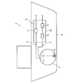
- FIG. 2 is a plan view schematically showing the machine room 20.
- the machine room 20 is a sealed chamber that forms a sealed space.
- the machine room 20 is configured to be ventilated, and an air supply port 21 and an exhaust port 22 are provided at appropriate positions in the machine room 20. That is, the air in the machine room 20 is forcibly exhausted from the exhaust port 22 by the unillustrated ventilator, and the air is sent from the air supply port 21 into the machine room 20.
- the first discharge line 4 and the second discharge line 5 have a plurality of possible leakage points 30 scattered in the machine room 20.
- the assumed leakage location is a location where the possibility of leakage of liquefied gas or evaporated gas flowing through the piping is relatively high.
- each of the plurality of assumed leakage points 30 is a valve, a joint, or a seal part of a device provided in a pipe constituting the first discharge line 4 and the second discharge line 5.
- the seal portion is a component that seals leakage of liquefied gas or evaporative gas between sliding surfaces of a rotary machine such as a compressor or a pump or a reciprocating machine.
- the first discharge line 4 has a flange joint 30a and a shut-off valve 30b located in the pipe portion 4a on the upstream side of the compressor 11 as a leakage assumed portion 30, and a seal portion 30c of the compressor 11.
- the flange joint 30d located in the pipe part 4b downstream from the compressor 11 is provided.
- a flange joint 30g, a flange joint 30h and a shut-off valve 30i located at 5b, and a flange joint 30j are provided on the pipe portion 5c downstream of the heater 13.
- flange joint”, “shut-off valve”, and “seal part” are all referred to as “leakage assumed locations”, and indicate any possible leak location among the assumed leak locations 30a to 30j. Will be referred to as a “presumed leak point 30”.
- these leak potential locations 30a to 30j are integrated and arranged at several locations in the machine room 20.
- the leakage assumed places 30 a to 30 d are arranged in the vicinity of the compressor 11, and the leakage assumed places 30 e to 30 g are arranged in the evaporator 12.
- the leak estimated locations 30 h to 30 j are arranged in the vicinity of the heater 13.
- the gas leak detection system 10 includes a first gas detector 41 and a plurality of (three in this example) second gas detectors in order to detect leakage of liquefied gas or evaporative gas from the expected leak locations 30a to 30j. 42a to 42c.
- the first gas detector 41 is installed at the exhaust port 22.
- the gas evaporated from the leaked liquefied gas or the leaked evaporated gas (hereinafter also simply referred to as “leaked gas”) always passes through the exhaust port 22.
- the detection sensitivity of the first gas detector 41 is set to high sensitivity (that is, the detection concentration is low) so that the gas is detected even when leaking from any leakage assumed location 30 in the machine room 20. By setting it, the leaked gas can be reliably detected.
- the detection concentration of the first gas detector 41 is determined, for example, by performing a computational fluid dynamics (CFD) analysis. Specifically, first, the minimum leakage speed of the fluid to be leaked is estimated from the assumed leakage hole diameter and the operating pressure or design pressure at each of the estimated leakage locations 30a to 30j. Then, the minimum leakage amount Q1 per unit time is calculated from the estimated minimum leakage speed. Next, CFD analysis was performed using the calculated minimum leakage amount Q1 and ventilation amount Q2 (for example, the amount of air discharged from the exhaust port 22 per unit time) as a boundary condition, and the first gas detector 41 was installed. Predict the concentration of leaked gas at the location. In this way, a safety factor is set to the predicted gas concentration, and the detected concentration is determined so that the first gas detector 41 can detect the gas leakage even when leaking from any leaking location 30 in the machine room 20. .
- CFD computational fluid dynamics
- the second gas detectors 42a to 42c are respectively installed in the vicinity of the plurality of assumed leakage points 30. Specifically, the second gas detector 42a is installed in the vicinity of the leak potential portions 30a to 30d that are close to each other. The second gas detector 42b is installed in the vicinity of the possible leakage locations 30e to 30g that are close to each other. The second gas detector 42c is installed in the vicinity of the expected leakage locations 30h to 30j that are close to each other.
- the second gas detector 42a is installed at a position where the leakage can be detected regardless of whether the evaporative gas leaks from any of the leak potential locations 30a to 30d.
- the second gas detector 42b is installed at a position where the leakage can be detected even when the liquefied gas or the evaporative gas leaks from any of the leakage assumed locations 30e to 30g.
- the second gas detector 42c is installed at a position where the leakage can be detected even if the evaporative gas leaks from any of the leakage assumed locations 30h to 30j.
- the second gas detectors 42a to 42c those having gas detection sensitivity lower than that of the first gas detector 41 are used. Then, when the liquefied gas or the evaporative gas leaks from a certain leak assumption location 30, one of the second gas detectors 42a to 42c detects the gas leak, and other than that, the gas leak is not detected. Two gas detectors 42a to 42c are arranged.
- the second gas detector 42a does not detect the leakage of the liquefied gas or the evaporative gas from any of the assumed leak locations 30d to 30j, and the second gas detector 42b does not detect the leak expected locations 30a to 30d,
- the leak of liquefied gas or evaporative gas from any of 30h to 30j is not detected, and the second gas detector 42c does not detect the leak of liquefied gas or evaporative gas from any of the assumed leak locations 30a to 30g.
- this is not the case when the leakage amount of the liquefied gas or the evaporative gas from the assumed leakage location 30 exceeds the expected amount.
- each of the second gas detectors 42a to 42c detects only gas leakage from the assumed leakage location 30 in the leakage estimated locations 30a to 30j, and leaks gas from the assumed leakage location 30 that is not located nearby. In order to prevent detection, not only the installation position but also the detection density is appropriately determined. In the present embodiment, the detected concentrations of the second gas detectors 42a to 42c are the same. However, the detected concentrations of the second gas detectors 42a to 42c may be different from each other. For example, the detection concentrations of the second gas detectors 42a to 42c are lower than the lower explosion limit (LEL), for example, 25% LEL, 30% LEL, 50% LEL, and the like.
- LEL lower explosion limit
- each installation of the second gas detectors 42a to 42c This is performed depending on the safety standards of the place and the method for determining the detected concentration of the first gas detector 41.
- the leaked gas is detected by the first gas detector 41, and among the three second gas detectors 42a to 42c, The gas is detected by the second gas detector 42a in the vicinity of the assumed leakage point 30a.
- the first gas detector 41 and the second gas detector 42a detect the gas, for example, a crew member in the bridge of the liquefied gas carrier 1 or the engine control room has a gas leak in the machine room 20 due to a visual audible alarm. I was informed. Since the second gas detector 42a has detected the gas, the sailor can specify that there is a leaking point in the vicinity of the second gas detector 42a including the leaking expected points 30a to 30d, and promptly deal with the leaking point. I do.
- the leaked gas in the unlikely event that liquefied gas or evaporative gas leaks from places other than the expected leak locations 30a to 30j, the leaked gas can be detected by the highly sensitive first gas detector 41 installed at the exhaust port 22. . In such a case, even if none of the second gas detectors 42a to 42c having low sensitivity detects the leaked gas, the leaked gas in the machine room 20 can be reliably detected.
- the leak detection system 10 when the liquefied gas or the evaporated gas leaks in the machine room 20, the leak is caused by the first gas detector 41 installed in the exhaust port 22. Gas can be detected reliably.
- the second gas detectors 42a to 42c have lower gas detection sensitivity than the first gas detector 41, when liquefied gas or evaporative gas leaks from a certain leak point 30 in the machine room 20, the gas is detected. It can be arranged so that the second gas detector installed in the vicinity of the leaked point detects the leaked gas and the other second gas detectors do not detect the leaked gas. For this reason, it is possible to quickly identify from which of the plurality of possible leakage locations 30a to 30j gas leakage has occurred.
- FIG. 3 is a plan view schematically showing the machine room 20 according to the modification.
- the machine room 20 shown in FIG. 3 is different from the above embodiment in the number and installation method of the second gas detectors installed in order to detect the leakage assumed location 30. That is, in the above-described embodiment, as shown in FIG. 2, one second gas detector is installed in the vicinity of a plurality of assumed leakage points. On the other hand, one second gas detector is installed in the vicinity thereof. Specifically, each of the second gas detectors 43a to 43j is installed correspondingly in the vicinity of each of the possible leak locations 30a to 30j.
- the installation position of the second gas detector is such that the concentration of the leaked gas that reaches the second gas detector is sufficiently high when gas leaks from an assumed leak location other than the assumed leak location that is the detection target. It is preferable to be determined to be low.
- the detected concentration of the second gas detector may be lower than the concentration of the leaked gas that reaches the second gas detector when the gas leaks from the assumed leak location other than the assumed leak location that is the detection target. preferable. However, this does not apply when the amount of leakage of liquefied gas or evaporative gas from the assumed leakage point exceeds the expected amount.
- the second gas detectors 43a to 43j may not be installed for all of the possible leak locations 30a to 30j.
- the second gas detector may be installed only in the vicinity of two possible leak locations that are particularly likely to leak among the expected leak locations 30a to 30j. In this case, when one of the two second gas detectors detects leaked gas, it is possible to quickly identify from which of the two leak assumed locations that are particularly likely to leak. .
- the liquefied gas carrier 1 shown in FIG. 1 is schematically shown, and the shape of the tank 3 and the machine room 20 and the size with respect to the hull 2 are limited to those shown in FIG. Not.
- the number of tanks 3 provided in the hull 2 may be plural, and the tank 3 may be arranged in the hull 2 so that the upper part protrudes above the upper deck of the hull 2.
- the machine room 20 may be provided above the upper deck of the hull 2.
- the 1st discharge line 4 and the 2nd discharge line 5 were arrange
- the number of pipes through which the liquefied gas or the evaporated gas vaporized in the machine chamber 20 flows may not be two, but may be one or three or more.
- the pipe that passes through the machine room 20 may be a pipe that constitutes one of the first discharge line 4 and the second discharge line 5.
- the present invention is configured to allow ventilation other than the machine room 20.
- the present invention can also be applied to a sealed room, and the present invention can also be applied to a sealed room provided on land facilities.
- Second discharge line 10 Gas leakage detection system 20: Machine room (sealed room) 21: Air supply port 22: Exhaust port 30 (30a-30j): Leakage expected location 41: First gas detectors 42a-42c: Second gas detectors 43a-42j: Second gas detectors
Landscapes
- Engineering & Computer Science (AREA)
- Physics & Mathematics (AREA)
- General Physics & Mathematics (AREA)
- Mechanical Engineering (AREA)
- Chemical & Material Sciences (AREA)
- Combustion & Propulsion (AREA)
- Ocean & Marine Engineering (AREA)
- General Engineering & Computer Science (AREA)
- Filling Or Discharging Of Gas Storage Vessels (AREA)
- Examining Or Testing Airtightness (AREA)
Abstract
Description
以下、本発明の一実施形態に係るガス漏洩検知システムを図面に基づいて説明する。
図3は、変形例に係る機械室20を模式的に示した平面図である。図3に示した機械室20は、上記実施形態とは、漏洩想定箇所30を検知するために設置する第2ガス検知器の数及び設置方法が異なる。即ち、上記実施形態では、図2に示したように、複数の漏洩想定箇所に対して、それらの近傍に1つの第2ガス検知器を設置したが、変形例では、1つの漏洩想定箇所に対して、その近傍に1つの第2ガス検知器を設置している。具体的には、第2ガス検知器43a~43jのそれぞれは、漏洩想定箇所30a~30jのそれぞれの近傍に、対応して設置されている。
本発明は上記の実施形態や変形例に限定されるものではなく、本発明の要旨を逸脱しない範囲で種々の変形が可能である。
2 :船体
3 :タンク
4 :第1排出ライン
5 :第2排出ライン
10 :ガス漏洩検知システム
20 :機械室(密閉室)
21 :給気口
22 :排気口
30(30a~30j) :漏洩想定箇所
41 :第1ガス検知器
42a~42c :第2ガス検知器
43a~42j :第2ガス検知器
Claims (3)
- 給気口及び排気口を備えて換気可能に構成された密閉室と、
液化ガス又はそれが気化した蒸発ガスが流れ、前記密閉室内に点在する複数の漏洩想定箇所を有する配管と、
前記排気口に設置された第1ガス検知器と、
前記第1ガス検知器よりもガス検知感度が低い少なくとも2つの第2ガス検知器であって、前記複数の漏洩想定箇所の少なくとも2つの近傍にそれぞれ設置された少なくとも2つの第2ガス検知器と、を備える、ガス漏洩検知システム。 - 前記複数の漏洩想定箇所のそれぞれは、前記配管に設けられた、弁、継手、又は機器のシール部である、請求項1に記載のガス漏洩検知システム。
- 密閉室に点在する複数の漏洩想定箇所のうちの1つの漏洩想定箇所からガスが漏洩した場合に、
前記密閉室の排気口に設置された第1ガス検知器によりガスを検知するとともに、
前記密閉室内に設置された、前記第1ガス検知器よりもガス検知感度が低い複数の第2ガス検知器のうち、ガスが漏洩した前記漏洩想定箇所の近傍に設置された1つの第2ガス検知器によりガスを検知する、ガス漏洩検知方法。
Priority Applications (3)
| Application Number | Priority Date | Filing Date | Title |
|---|---|---|---|
| KR1020207000232A KR102368572B1 (ko) | 2017-06-06 | 2018-06-06 | 가스 누설 검지 시스템 및 가스 누설 검지 방법 |
| EP18814275.6A EP3637079B1 (en) | 2017-06-06 | 2018-06-06 | Gas leakage detection system and gas leakage detection |
| CN201880037383.6A CN110709684B (zh) | 2017-06-06 | 2018-06-06 | 气体泄漏检测系统以及气体泄漏检测方法 |
Applications Claiming Priority (2)
| Application Number | Priority Date | Filing Date | Title |
|---|---|---|---|
| JP2017111752A JP6867887B2 (ja) | 2017-06-06 | 2017-06-06 | ガス漏洩検知システム及びガス漏洩検知方法 |
| JP2017-111752 | 2017-06-06 |
Publications (1)
| Publication Number | Publication Date |
|---|---|
| WO2018225762A1 true WO2018225762A1 (ja) | 2018-12-13 |
Family
ID=64567440
Family Applications (1)
| Application Number | Title | Priority Date | Filing Date |
|---|---|---|---|
| PCT/JP2018/021652 Ceased WO2018225762A1 (ja) | 2017-06-06 | 2018-06-06 | ガス漏洩検知システム及びガス漏洩検知方法 |
Country Status (5)
| Country | Link |
|---|---|
| EP (1) | EP3637079B1 (ja) |
| JP (1) | JP6867887B2 (ja) |
| KR (1) | KR102368572B1 (ja) |
| CN (1) | CN110709684B (ja) |
| WO (1) | WO2018225762A1 (ja) |
Families Citing this family (3)
| Publication number | Priority date | Publication date | Assignee | Title |
|---|---|---|---|---|
| KR102256218B1 (ko) * | 2020-03-20 | 2021-05-26 | 군산대학교산학협력단 | 소형선박 선미부에 구비되는 소형선박용 액화 가스연료 공급 보관 시설 |
| KR20260005366A (ko) * | 2023-05-24 | 2026-01-09 | 카와사키 주코교 카부시키 카이샤 | 부체 구조물 |
| WO2025172601A1 (de) * | 2024-02-16 | 2025-08-21 | Linde Gmbh | Speicherbehälter und verfahren |
Citations (6)
| Publication number | Priority date | Publication date | Assignee | Title |
|---|---|---|---|---|
| JPS59149044U (ja) * | 1983-03-25 | 1984-10-05 | 三菱重工業株式会社 | 有害ガス検出装置 |
| JPH11166698A (ja) * | 1997-12-02 | 1999-06-22 | Nippon Air Liquide Kk | ガス漏れ検知装置 |
| US6025788A (en) * | 1995-11-24 | 2000-02-15 | First Smart Sensor Corp. | Integrated local or remote control liquid gas leak detection and shut-off system |
| JP2006047066A (ja) * | 2004-08-03 | 2006-02-16 | Toyota Motor Corp | ガス漏洩検出機構 |
| JP2009063313A (ja) * | 2007-09-04 | 2009-03-26 | Kansai Electric Power Co Inc:The | ガス漏洩監視システム |
| JP2017025736A (ja) | 2015-07-17 | 2017-02-02 | 三井造船株式会社 | 船舶用の燃料ガス供給システム |
Family Cites Families (11)
| Publication number | Priority date | Publication date | Assignee | Title |
|---|---|---|---|---|
| FR2494848A1 (fr) * | 1980-11-24 | 1982-05-28 | Technigaz | Procede et dispositif de detection, a distance, de defauts d'etancheite d'une conduite de transport d'un fluide, immergee dans un fluide ambiant; conduite de transport comprenant ce dispositif de detection et procede de construction d'une telle conduite |
| JP2006522335A (ja) * | 2003-03-06 | 2006-09-28 | シンシナティ テスト システムズ,インコーポレイテッド | ガスを検出する方法及び装置 |
| JP2005299394A (ja) * | 2004-04-06 | 2005-10-27 | Mitsubishi Electric Corp | 蒸散燃料ガスリーク検出装置 |
| KR100787777B1 (ko) * | 2007-03-09 | 2007-12-24 | 현대중공업 주식회사 | 보일오프가스 활용설비의 밀폐공간내 누출가스 감지 및환기 방법 |
| DE102010048982B4 (de) * | 2010-09-03 | 2022-06-09 | Inficon Gmbh | Lecksuchgerät |
| CN102279082B (zh) * | 2011-04-20 | 2013-07-17 | 清华大学 | 一种石油化工水冷器泄漏在线监测方法 |
| CN102840058B (zh) * | 2012-09-14 | 2015-03-11 | 中国舰船研究设计中心 | Lng燃料动力船用储液供气系统 |
| EP2902610A4 (en) * | 2012-09-25 | 2015-10-07 | Toyota Motor Co Ltd | LEAK DIAGNOSIS DEVICE FOR SYSTEM FOR PROCESSING EVAPORATED FUELS |
| CN103407567B (zh) * | 2013-07-30 | 2016-03-30 | 武汉理工大学 | 液化天然气动力船集成化动力控制装置 |
| CN104019359B (zh) * | 2014-06-09 | 2017-01-18 | 山东交通学院 | 一种lng单燃料船舶燃气系统的保护装置 |
| CN205468761U (zh) * | 2016-02-05 | 2016-08-17 | 十堰振峰机械科技有限公司 | 具有燃气泄漏检测功能的汽车 |
-
2017
- 2017-06-06 JP JP2017111752A patent/JP6867887B2/ja active Active
-
2018
- 2018-06-06 KR KR1020207000232A patent/KR102368572B1/ko active Active
- 2018-06-06 EP EP18814275.6A patent/EP3637079B1/en active Active
- 2018-06-06 WO PCT/JP2018/021652 patent/WO2018225762A1/ja not_active Ceased
- 2018-06-06 CN CN201880037383.6A patent/CN110709684B/zh active Active
Patent Citations (6)
| Publication number | Priority date | Publication date | Assignee | Title |
|---|---|---|---|---|
| JPS59149044U (ja) * | 1983-03-25 | 1984-10-05 | 三菱重工業株式会社 | 有害ガス検出装置 |
| US6025788A (en) * | 1995-11-24 | 2000-02-15 | First Smart Sensor Corp. | Integrated local or remote control liquid gas leak detection and shut-off system |
| JPH11166698A (ja) * | 1997-12-02 | 1999-06-22 | Nippon Air Liquide Kk | ガス漏れ検知装置 |
| JP2006047066A (ja) * | 2004-08-03 | 2006-02-16 | Toyota Motor Corp | ガス漏洩検出機構 |
| JP2009063313A (ja) * | 2007-09-04 | 2009-03-26 | Kansai Electric Power Co Inc:The | ガス漏洩監視システム |
| JP2017025736A (ja) | 2015-07-17 | 2017-02-02 | 三井造船株式会社 | 船舶用の燃料ガス供給システム |
Also Published As
| Publication number | Publication date |
|---|---|
| EP3637079A4 (en) | 2021-03-24 |
| JP6867887B2 (ja) | 2021-05-12 |
| EP3637079B1 (en) | 2025-11-05 |
| CN110709684A (zh) | 2020-01-17 |
| CN110709684B (zh) | 2021-09-10 |
| KR102368572B1 (ko) | 2022-02-28 |
| EP3637079A1 (en) | 2020-04-15 |
| KR20200014413A (ko) | 2020-02-10 |
| JP2018205170A (ja) | 2018-12-27 |
Similar Documents
| Publication | Publication Date | Title |
|---|---|---|
| US8621913B2 (en) | Use of hydrogen sensor to detect hydrogen storage system pressure regulator failure | |
| KR101919924B1 (ko) | 가스 배관 시스템 및 이를 탑재한 선박 | |
| WO2018225762A1 (ja) | ガス漏洩検知システム及びガス漏洩検知方法 | |
| US12018791B2 (en) | System for circulating air through double pipes for supplying gas and air circulation method using same | |
| KR20150137812A (ko) | 선박의 연료가스 공급장치 및 선박의 연료가스 공급방법 | |
| KR20130119306A (ko) | 액화물 가열기의 누출 감지 및 차단 시스템 | |
| KR20170022667A (ko) | 액화가스 저장탱크의 누출 액화가스 처리 시스템 및 방법 | |
| KR101407720B1 (ko) | Lng용 이중 배관의 성능평가 장치 | |
| KR20230076898A (ko) | 선박의 암모니아 가스 처리시스템 | |
| KR20230104987A (ko) | 액화가스용 진공 단열 배관 유닛 및 액화가스용 진공 단열 배관의 파손 검지 방법 | |
| KR20140124523A (ko) | 연료공급장치 | |
| US11326978B2 (en) | Leak indicating clamp | |
| KR100888339B1 (ko) | 해상구조물에서 lng 재기화에 이용된 유체의 처리 방법및 시스템 | |
| JP6327002B2 (ja) | 仕切弁用漏れ検知装置 | |
| Jeong et al. | Quantitative risk assessment of medium-sized floating regasification units using system hierarchical modelling | |
| JP6023900B2 (ja) | ガスエンジンの燃料ガス供給装置 | |
| KR20180036774A (ko) | 파이프 시스템을 구비한 선박상의 손상 제한 | |
| KR20140132029A (ko) | 선박의 엔진실 압력조절장치 | |
| KR101868316B1 (ko) | 반도체 제조용 가스 공급장치 | |
| US11359748B2 (en) | Connection system between a distribution member and a receiving member and leak detection method | |
| US10578085B1 (en) | Sealed modular fluid distribution system | |
| KR102348462B1 (ko) | 선박의 선체 외벽 보호 시스템 | |
| KR100815982B1 (ko) | 시일포트의 가스누출 자동 감지장치 | |
| KR101996393B1 (ko) | 미량의 누설 액화가스를 감지할 수 있는 저장유닛 및 이를 사용한 선박 | |
| KR20220145979A (ko) | 엔진의 가스연료 공급장치 및 이를 포함하는 선박 |
Legal Events
| Date | Code | Title | Description |
|---|---|---|---|
| 121 | Ep: the epo has been informed by wipo that ep was designated in this application |
Ref document number: 18814275 Country of ref document: EP Kind code of ref document: A1 |
|
| NENP | Non-entry into the national phase |
Ref country code: DE |
|
| ENP | Entry into the national phase |
Ref document number: 20207000232 Country of ref document: KR Kind code of ref document: A |
|
| ENP | Entry into the national phase |
Ref document number: 2018814275 Country of ref document: EP Effective date: 20200107 |
|
| WWG | Wipo information: grant in national office |
Ref document number: 2018814275 Country of ref document: EP |