WO2018225938A1 - 금속 패턴 필름 및 이의 제조 방법 - Google Patents
금속 패턴 필름 및 이의 제조 방법 Download PDFInfo
- Publication number
- WO2018225938A1 WO2018225938A1 PCT/KR2018/003607 KR2018003607W WO2018225938A1 WO 2018225938 A1 WO2018225938 A1 WO 2018225938A1 KR 2018003607 W KR2018003607 W KR 2018003607W WO 2018225938 A1 WO2018225938 A1 WO 2018225938A1
- Authority
- WO
- WIPO (PCT)
- Prior art keywords
- metal pattern
- layer
- adhesion promoting
- substrate
- metal
- Prior art date
- Legal status (The legal status is an assumption and is not a legal conclusion. Google has not performed a legal analysis and makes no representation as to the accuracy of the status listed.)
- Ceased
Links
Images


Classifications
-
- B—PERFORMING OPERATIONS; TRANSPORTING
- B32—LAYERED PRODUCTS
- B32B—LAYERED PRODUCTS, i.e. PRODUCTS BUILT-UP OF STRATA OF FLAT OR NON-FLAT, e.g. CELLULAR OR HONEYCOMB, FORM
- B32B17/00—Layered products essentially comprising sheet glass, or glass, slag, or like fibres
- B32B17/06—Layered products essentially comprising sheet glass, or glass, slag, or like fibres comprising glass as the main or only constituent of a layer, next to another layer of a specific material
- B32B17/10—Layered products essentially comprising sheet glass, or glass, slag, or like fibres comprising glass as the main or only constituent of a layer, next to another layer of a specific material of synthetic resin
- B32B17/10005—Layered products essentially comprising sheet glass, or glass, slag, or like fibres comprising glass as the main or only constituent of a layer, next to another layer of a specific material of synthetic resin laminated safety glass or glazing
- B32B17/10165—Functional features of the laminated safety glass or glazing
- B32B17/10174—Coatings of a metallic or dielectric material on a constituent layer of glass or polymer
- B32B17/10183—Coatings of a metallic or dielectric material on a constituent layer of glass or polymer being not continuous, e.g. in edge regions
-
- B—PERFORMING OPERATIONS; TRANSPORTING
- B32—LAYERED PRODUCTS
- B32B—LAYERED PRODUCTS, i.e. PRODUCTS BUILT-UP OF STRATA OF FLAT OR NON-FLAT, e.g. CELLULAR OR HONEYCOMB, FORM
- B32B9/00—Layered products comprising a layer of a particular substance not covered by groups B32B11/00 - B32B29/00
- B32B9/04—Layered products comprising a layer of a particular substance not covered by groups B32B11/00 - B32B29/00 comprising such particular substance as the main or only constituent of a layer, which is next to another layer of the same or of a different material
- B32B9/041—Layered products comprising a layer of a particular substance not covered by groups B32B11/00 - B32B29/00 comprising such particular substance as the main or only constituent of a layer, which is next to another layer of the same or of a different material of metal
-
- B—PERFORMING OPERATIONS; TRANSPORTING
- B32—LAYERED PRODUCTS
- B32B—LAYERED PRODUCTS, i.e. PRODUCTS BUILT-UP OF STRATA OF FLAT OR NON-FLAT, e.g. CELLULAR OR HONEYCOMB, FORM
- B32B17/00—Layered products essentially comprising sheet glass, or glass, slag, or like fibres
- B32B17/06—Layered products essentially comprising sheet glass, or glass, slag, or like fibres comprising glass as the main or only constituent of a layer, next to another layer of a specific material
- B32B17/10—Layered products essentially comprising sheet glass, or glass, slag, or like fibres comprising glass as the main or only constituent of a layer, next to another layer of a specific material of synthetic resin
- B32B17/10005—Layered products essentially comprising sheet glass, or glass, slag, or like fibres comprising glass as the main or only constituent of a layer, next to another layer of a specific material of synthetic resin laminated safety glass or glazing
- B32B17/10009—Layered products essentially comprising sheet glass, or glass, slag, or like fibres comprising glass as the main or only constituent of a layer, next to another layer of a specific material of synthetic resin laminated safety glass or glazing characterized by the number, the constitution or treatment of glass sheets
- B32B17/10036—Layered products essentially comprising sheet glass, or glass, slag, or like fibres comprising glass as the main or only constituent of a layer, next to another layer of a specific material of synthetic resin laminated safety glass or glazing characterized by the number, the constitution or treatment of glass sheets comprising two outer glass sheets
-
- B—PERFORMING OPERATIONS; TRANSPORTING
- B32—LAYERED PRODUCTS
- B32B—LAYERED PRODUCTS, i.e. PRODUCTS BUILT-UP OF STRATA OF FLAT OR NON-FLAT, e.g. CELLULAR OR HONEYCOMB, FORM
- B32B17/00—Layered products essentially comprising sheet glass, or glass, slag, or like fibres
- B32B17/06—Layered products essentially comprising sheet glass, or glass, slag, or like fibres comprising glass as the main or only constituent of a layer, next to another layer of a specific material
- B32B17/061—Layered products essentially comprising sheet glass, or glass, slag, or like fibres comprising glass as the main or only constituent of a layer, next to another layer of a specific material of metal
-
- B—PERFORMING OPERATIONS; TRANSPORTING
- B32—LAYERED PRODUCTS
- B32B—LAYERED PRODUCTS, i.e. PRODUCTS BUILT-UP OF STRATA OF FLAT OR NON-FLAT, e.g. CELLULAR OR HONEYCOMB, FORM
- B32B17/00—Layered products essentially comprising sheet glass, or glass, slag, or like fibres
- B32B17/06—Layered products essentially comprising sheet glass, or glass, slag, or like fibres comprising glass as the main or only constituent of a layer, next to another layer of a specific material
- B32B17/10—Layered products essentially comprising sheet glass, or glass, slag, or like fibres comprising glass as the main or only constituent of a layer, next to another layer of a specific material of synthetic resin
- B32B17/10005—Layered products essentially comprising sheet glass, or glass, slag, or like fibres comprising glass as the main or only constituent of a layer, next to another layer of a specific material of synthetic resin laminated safety glass or glazing
- B32B17/10009—Layered products essentially comprising sheet glass, or glass, slag, or like fibres comprising glass as the main or only constituent of a layer, next to another layer of a specific material of synthetic resin laminated safety glass or glazing characterized by the number, the constitution or treatment of glass sheets
- B32B17/10018—Layered products essentially comprising sheet glass, or glass, slag, or like fibres comprising glass as the main or only constituent of a layer, next to another layer of a specific material of synthetic resin laminated safety glass or glazing characterized by the number, the constitution or treatment of glass sheets comprising only one glass sheet
-
- B—PERFORMING OPERATIONS; TRANSPORTING
- B32—LAYERED PRODUCTS
- B32B—LAYERED PRODUCTS, i.e. PRODUCTS BUILT-UP OF STRATA OF FLAT OR NON-FLAT, e.g. CELLULAR OR HONEYCOMB, FORM
- B32B17/00—Layered products essentially comprising sheet glass, or glass, slag, or like fibres
- B32B17/06—Layered products essentially comprising sheet glass, or glass, slag, or like fibres comprising glass as the main or only constituent of a layer, next to another layer of a specific material
- B32B17/10—Layered products essentially comprising sheet glass, or glass, slag, or like fibres comprising glass as the main or only constituent of a layer, next to another layer of a specific material of synthetic resin
- B32B17/10005—Layered products essentially comprising sheet glass, or glass, slag, or like fibres comprising glass as the main or only constituent of a layer, next to another layer of a specific material of synthetic resin laminated safety glass or glazing
- B32B17/10165—Functional features of the laminated safety glass or glazing
- B32B17/10174—Coatings of a metallic or dielectric material on a constituent layer of glass or polymer
- B32B17/10183—Coatings of a metallic or dielectric material on a constituent layer of glass or polymer being not continuous, e.g. in edge regions
- B32B17/10192—Coatings of a metallic or dielectric material on a constituent layer of glass or polymer being not continuous, e.g. in edge regions patterned in the form of columns or grids
-
- B—PERFORMING OPERATIONS; TRANSPORTING
- B32—LAYERED PRODUCTS
- B32B—LAYERED PRODUCTS, i.e. PRODUCTS BUILT-UP OF STRATA OF FLAT OR NON-FLAT, e.g. CELLULAR OR HONEYCOMB, FORM
- B32B17/00—Layered products essentially comprising sheet glass, or glass, slag, or like fibres
- B32B17/06—Layered products essentially comprising sheet glass, or glass, slag, or like fibres comprising glass as the main or only constituent of a layer, next to another layer of a specific material
- B32B17/10—Layered products essentially comprising sheet glass, or glass, slag, or like fibres comprising glass as the main or only constituent of a layer, next to another layer of a specific material of synthetic resin
- B32B17/10005—Layered products essentially comprising sheet glass, or glass, slag, or like fibres comprising glass as the main or only constituent of a layer, next to another layer of a specific material of synthetic resin laminated safety glass or glazing
- B32B17/10165—Functional features of the laminated safety glass or glazing
- B32B17/10174—Coatings of a metallic or dielectric material on a constituent layer of glass or polymer
- B32B17/10201—Dielectric coatings
-
- B—PERFORMING OPERATIONS; TRANSPORTING
- B32—LAYERED PRODUCTS
- B32B—LAYERED PRODUCTS, i.e. PRODUCTS BUILT-UP OF STRATA OF FLAT OR NON-FLAT, e.g. CELLULAR OR HONEYCOMB, FORM
- B32B17/00—Layered products essentially comprising sheet glass, or glass, slag, or like fibres
- B32B17/06—Layered products essentially comprising sheet glass, or glass, slag, or like fibres comprising glass as the main or only constituent of a layer, next to another layer of a specific material
- B32B17/10—Layered products essentially comprising sheet glass, or glass, slag, or like fibres comprising glass as the main or only constituent of a layer, next to another layer of a specific material of synthetic resin
- B32B17/10005—Layered products essentially comprising sheet glass, or glass, slag, or like fibres comprising glass as the main or only constituent of a layer, next to another layer of a specific material of synthetic resin laminated safety glass or glazing
- B32B17/10165—Functional features of the laminated safety glass or glazing
- B32B17/10174—Coatings of a metallic or dielectric material on a constituent layer of glass or polymer
- B32B17/1022—Metallic coatings
-
- B—PERFORMING OPERATIONS; TRANSPORTING
- B32—LAYERED PRODUCTS
- B32B—LAYERED PRODUCTS, i.e. PRODUCTS BUILT-UP OF STRATA OF FLAT OR NON-FLAT, e.g. CELLULAR OR HONEYCOMB, FORM
- B32B17/00—Layered products essentially comprising sheet glass, or glass, slag, or like fibres
- B32B17/06—Layered products essentially comprising sheet glass, or glass, slag, or like fibres comprising glass as the main or only constituent of a layer, next to another layer of a specific material
- B32B17/10—Layered products essentially comprising sheet glass, or glass, slag, or like fibres comprising glass as the main or only constituent of a layer, next to another layer of a specific material of synthetic resin
- B32B17/10005—Layered products essentially comprising sheet glass, or glass, slag, or like fibres comprising glass as the main or only constituent of a layer, next to another layer of a specific material of synthetic resin laminated safety glass or glazing
- B32B17/1055—Layered products essentially comprising sheet glass, or glass, slag, or like fibres comprising glass as the main or only constituent of a layer, next to another layer of a specific material of synthetic resin laminated safety glass or glazing characterized by the resin layer, i.e. interlayer
- B32B17/10761—Layered products essentially comprising sheet glass, or glass, slag, or like fibres comprising glass as the main or only constituent of a layer, next to another layer of a specific material of synthetic resin laminated safety glass or glazing characterized by the resin layer, i.e. interlayer containing vinyl acetal
-
- B—PERFORMING OPERATIONS; TRANSPORTING
- B32—LAYERED PRODUCTS
- B32B—LAYERED PRODUCTS, i.e. PRODUCTS BUILT-UP OF STRATA OF FLAT OR NON-FLAT, e.g. CELLULAR OR HONEYCOMB, FORM
- B32B17/00—Layered products essentially comprising sheet glass, or glass, slag, or like fibres
- B32B17/06—Layered products essentially comprising sheet glass, or glass, slag, or like fibres comprising glass as the main or only constituent of a layer, next to another layer of a specific material
- B32B17/10—Layered products essentially comprising sheet glass, or glass, slag, or like fibres comprising glass as the main or only constituent of a layer, next to another layer of a specific material of synthetic resin
- B32B17/10005—Layered products essentially comprising sheet glass, or glass, slag, or like fibres comprising glass as the main or only constituent of a layer, next to another layer of a specific material of synthetic resin laminated safety glass or glazing
- B32B17/1055—Layered products essentially comprising sheet glass, or glass, slag, or like fibres comprising glass as the main or only constituent of a layer, next to another layer of a specific material of synthetic resin laminated safety glass or glazing characterized by the resin layer, i.e. interlayer
- B32B17/1077—Layered products essentially comprising sheet glass, or glass, slag, or like fibres comprising glass as the main or only constituent of a layer, next to another layer of a specific material of synthetic resin laminated safety glass or glazing characterized by the resin layer, i.e. interlayer containing polyurethane
-
- B—PERFORMING OPERATIONS; TRANSPORTING
- B32—LAYERED PRODUCTS
- B32B—LAYERED PRODUCTS, i.e. PRODUCTS BUILT-UP OF STRATA OF FLAT OR NON-FLAT, e.g. CELLULAR OR HONEYCOMB, FORM
- B32B17/00—Layered products essentially comprising sheet glass, or glass, slag, or like fibres
- B32B17/06—Layered products essentially comprising sheet glass, or glass, slag, or like fibres comprising glass as the main or only constituent of a layer, next to another layer of a specific material
- B32B17/10—Layered products essentially comprising sheet glass, or glass, slag, or like fibres comprising glass as the main or only constituent of a layer, next to another layer of a specific material of synthetic resin
- B32B17/10005—Layered products essentially comprising sheet glass, or glass, slag, or like fibres comprising glass as the main or only constituent of a layer, next to another layer of a specific material of synthetic resin laminated safety glass or glazing
- B32B17/1055—Layered products essentially comprising sheet glass, or glass, slag, or like fibres comprising glass as the main or only constituent of a layer, next to another layer of a specific material of synthetic resin laminated safety glass or glazing characterized by the resin layer, i.e. interlayer
- B32B17/10779—Layered products essentially comprising sheet glass, or glass, slag, or like fibres comprising glass as the main or only constituent of a layer, next to another layer of a specific material of synthetic resin laminated safety glass or glazing characterized by the resin layer, i.e. interlayer containing polyester
-
- B—PERFORMING OPERATIONS; TRANSPORTING
- B32—LAYERED PRODUCTS
- B32B—LAYERED PRODUCTS, i.e. PRODUCTS BUILT-UP OF STRATA OF FLAT OR NON-FLAT, e.g. CELLULAR OR HONEYCOMB, FORM
- B32B17/00—Layered products essentially comprising sheet glass, or glass, slag, or like fibres
- B32B17/06—Layered products essentially comprising sheet glass, or glass, slag, or like fibres comprising glass as the main or only constituent of a layer, next to another layer of a specific material
- B32B17/10—Layered products essentially comprising sheet glass, or glass, slag, or like fibres comprising glass as the main or only constituent of a layer, next to another layer of a specific material of synthetic resin
- B32B17/10005—Layered products essentially comprising sheet glass, or glass, slag, or like fibres comprising glass as the main or only constituent of a layer, next to another layer of a specific material of synthetic resin laminated safety glass or glazing
- B32B17/1055—Layered products essentially comprising sheet glass, or glass, slag, or like fibres comprising glass as the main or only constituent of a layer, next to another layer of a specific material of synthetic resin laminated safety glass or glazing characterized by the resin layer, i.e. interlayer
- B32B17/10788—Layered products essentially comprising sheet glass, or glass, slag, or like fibres comprising glass as the main or only constituent of a layer, next to another layer of a specific material of synthetic resin laminated safety glass or glazing characterized by the resin layer, i.e. interlayer containing ethylene vinylacetate
-
- B—PERFORMING OPERATIONS; TRANSPORTING
- B32—LAYERED PRODUCTS
- B32B—LAYERED PRODUCTS, i.e. PRODUCTS BUILT-UP OF STRATA OF FLAT OR NON-FLAT, e.g. CELLULAR OR HONEYCOMB, FORM
- B32B38/00—Ancillary operations in connection with laminating processes
- B32B38/10—Removing layers, or parts of layers, mechanically or chemically
-
- B—PERFORMING OPERATIONS; TRANSPORTING
- B32—LAYERED PRODUCTS
- B32B—LAYERED PRODUCTS, i.e. PRODUCTS BUILT-UP OF STRATA OF FLAT OR NON-FLAT, e.g. CELLULAR OR HONEYCOMB, FORM
- B32B7/00—Layered products characterised by the relation between layers; Layered products characterised by the relative orientation of features between layers, or by the relative values of a measurable parameter between layers, i.e. products comprising layers having different physical, chemical or physicochemical properties; Layered products characterised by the interconnection of layers
- B32B7/04—Interconnection of layers
- B32B7/12—Interconnection of layers using interposed adhesives or interposed materials with bonding properties
-
- C—CHEMISTRY; METALLURGY
- C09—DYES; PAINTS; POLISHES; NATURAL RESINS; ADHESIVES; COMPOSITIONS NOT OTHERWISE PROVIDED FOR; APPLICATIONS OF MATERIALS NOT OTHERWISE PROVIDED FOR
- C09J—ADHESIVES; NON-MECHANICAL ASPECTS OF ADHESIVE PROCESSES IN GENERAL; ADHESIVE PROCESSES NOT PROVIDED FOR ELSEWHERE; USE OF MATERIALS AS ADHESIVES
- C09J129/00—Adhesives based on homopolymers or copolymers of compounds having one or more unsaturated aliphatic radicals, each having only one carbon-to-carbon double bond, and at least one being terminated by an alcohol, ether, aldehydo, ketonic, acetal, or ketal radical; Adhesives based on hydrolysed polymers of esters of unsaturated alcohols with saturated carboxylic acids; Adhesives based on derivatives of such polymers
- C09J129/02—Homopolymers or copolymers of unsaturated alcohols
- C09J129/04—Polyvinyl alcohol; Partially hydrolysed homopolymers or copolymers of esters of unsaturated alcohols with saturated carboxylic acids
-
- C—CHEMISTRY; METALLURGY
- C09—DYES; PAINTS; POLISHES; NATURAL RESINS; ADHESIVES; COMPOSITIONS NOT OTHERWISE PROVIDED FOR; APPLICATIONS OF MATERIALS NOT OTHERWISE PROVIDED FOR
- C09J—ADHESIVES; NON-MECHANICAL ASPECTS OF ADHESIVE PROCESSES IN GENERAL; ADHESIVE PROCESSES NOT PROVIDED FOR ELSEWHERE; USE OF MATERIALS AS ADHESIVES
- C09J167/00—Adhesives based on polyesters obtained by reactions forming a carboxylic ester link in the main chain; Adhesives based on derivatives of such polymers
- C09J167/02—Polyesters derived from dicarboxylic acids and dihydroxy compounds
-
- C—CHEMISTRY; METALLURGY
- C23—COATING METALLIC MATERIAL; COATING MATERIAL WITH METALLIC MATERIAL; CHEMICAL SURFACE TREATMENT; DIFFUSION TREATMENT OF METALLIC MATERIAL; COATING BY VACUUM EVAPORATION, BY SPUTTERING, BY ION IMPLANTATION OR BY CHEMICAL VAPOUR DEPOSITION, IN GENERAL; INHIBITING CORROSION OF METALLIC MATERIAL OR INCRUSTATION IN GENERAL
- C23C—COATING METALLIC MATERIAL; COATING MATERIAL WITH METALLIC MATERIAL; SURFACE TREATMENT OF METALLIC MATERIAL BY DIFFUSION INTO THE SURFACE, BY CHEMICAL CONVERSION OR SUBSTITUTION; COATING BY VACUUM EVAPORATION, BY SPUTTERING, BY ION IMPLANTATION OR BY CHEMICAL VAPOUR DEPOSITION, IN GENERAL
- C23C14/00—Coating by vacuum evaporation, by sputtering or by ion implantation of the coating forming material
- C23C14/06—Coating by vacuum evaporation, by sputtering or by ion implantation of the coating forming material characterised by the coating material
- C23C14/08—Oxides
-
- C—CHEMISTRY; METALLURGY
- C23—COATING METALLIC MATERIAL; COATING MATERIAL WITH METALLIC MATERIAL; CHEMICAL SURFACE TREATMENT; DIFFUSION TREATMENT OF METALLIC MATERIAL; COATING BY VACUUM EVAPORATION, BY SPUTTERING, BY ION IMPLANTATION OR BY CHEMICAL VAPOUR DEPOSITION, IN GENERAL; INHIBITING CORROSION OF METALLIC MATERIAL OR INCRUSTATION IN GENERAL
- C23C—COATING METALLIC MATERIAL; COATING MATERIAL WITH METALLIC MATERIAL; SURFACE TREATMENT OF METALLIC MATERIAL BY DIFFUSION INTO THE SURFACE, BY CHEMICAL CONVERSION OR SUBSTITUTION; COATING BY VACUUM EVAPORATION, BY SPUTTERING, BY ION IMPLANTATION OR BY CHEMICAL VAPOUR DEPOSITION, IN GENERAL
- C23C14/00—Coating by vacuum evaporation, by sputtering or by ion implantation of the coating forming material
- C23C14/22—Coating by vacuum evaporation, by sputtering or by ion implantation of the coating forming material characterised by the process of coating
- C23C14/24—Vacuum evaporation
- C23C14/28—Vacuum evaporation by wave energy or particle radiation
- C23C14/30—Vacuum evaporation by wave energy or particle radiation by electron bombardment
-
- C—CHEMISTRY; METALLURGY
- C23—COATING METALLIC MATERIAL; COATING MATERIAL WITH METALLIC MATERIAL; CHEMICAL SURFACE TREATMENT; DIFFUSION TREATMENT OF METALLIC MATERIAL; COATING BY VACUUM EVAPORATION, BY SPUTTERING, BY ION IMPLANTATION OR BY CHEMICAL VAPOUR DEPOSITION, IN GENERAL; INHIBITING CORROSION OF METALLIC MATERIAL OR INCRUSTATION IN GENERAL
- C23C—COATING METALLIC MATERIAL; COATING MATERIAL WITH METALLIC MATERIAL; SURFACE TREATMENT OF METALLIC MATERIAL BY DIFFUSION INTO THE SURFACE, BY CHEMICAL CONVERSION OR SUBSTITUTION; COATING BY VACUUM EVAPORATION, BY SPUTTERING, BY ION IMPLANTATION OR BY CHEMICAL VAPOUR DEPOSITION, IN GENERAL
- C23C14/00—Coating by vacuum evaporation, by sputtering or by ion implantation of the coating forming material
- C23C14/22—Coating by vacuum evaporation, by sputtering or by ion implantation of the coating forming material characterised by the process of coating
- C23C14/34—Sputtering
-
- C—CHEMISTRY; METALLURGY
- C23—COATING METALLIC MATERIAL; COATING MATERIAL WITH METALLIC MATERIAL; CHEMICAL SURFACE TREATMENT; DIFFUSION TREATMENT OF METALLIC MATERIAL; COATING BY VACUUM EVAPORATION, BY SPUTTERING, BY ION IMPLANTATION OR BY CHEMICAL VAPOUR DEPOSITION, IN GENERAL; INHIBITING CORROSION OF METALLIC MATERIAL OR INCRUSTATION IN GENERAL
- C23F—NON-MECHANICAL REMOVAL OF METALLIC MATERIAL FROM SURFACE; INHIBITING CORROSION OF METALLIC MATERIAL OR INCRUSTATION IN GENERAL; MULTI-STEP PROCESSES FOR SURFACE TREATMENT OF METALLIC MATERIAL INVOLVING AT LEAST ONE PROCESS PROVIDED FOR IN CLASS C23 AND AT LEAST ONE PROCESS COVERED BY SUBCLASS C21D OR C22F OR CLASS C25
- C23F1/00—Etching metallic material by chemical means
- C23F1/02—Local etching
-
- Y—GENERAL TAGGING OF NEW TECHNOLOGICAL DEVELOPMENTS; GENERAL TAGGING OF CROSS-SECTIONAL TECHNOLOGIES SPANNING OVER SEVERAL SECTIONS OF THE IPC; TECHNICAL SUBJECTS COVERED BY FORMER USPC CROSS-REFERENCE ART COLLECTIONS [XRACs] AND DIGESTS
- Y10—TECHNICAL SUBJECTS COVERED BY FORMER USPC
- Y10T—TECHNICAL SUBJECTS COVERED BY FORMER US CLASSIFICATION
- Y10T428/00—Stock material or miscellaneous articles
- Y10T428/24—Structurally defined web or sheet [e.g., overall dimension, etc.]
- Y10T428/24802—Discontinuous or differential coating, impregnation or bond [e.g., artwork, printing, retouched photograph, etc.]
- Y10T428/24917—Discontinuous or differential coating, impregnation or bond [e.g., artwork, printing, retouched photograph, etc.] including metal layer
Definitions
- the present application provides a metal pattern film including the adhesion promoting layer and a method of manufacturing the same.
- polyvinyl butyral In the manufacture of functional laminated glass used for automobiles or construction, polyvinyl butyral (PVB) is generally used as an adhesive. Laminated glass with a special function is produced by a thermocompression process by sandwiching a polyvinyl butyral (PVB) laminated functional film between two glasses.
- the adhesion between the polyvinyl butyral (PVB) and the functional film must be at a certain level or higher, and in order to be reprocessed, the adhesive force must be at a level capable of peeling.
- PET film is used as a functional film commonly used in the past, and PET film generates stick-slip phenomenon when peeling off. Because of this, wrinkles and stains remain and cannot be reused. Therefore, in the production of functional laminated glass, there is a need for a metal pattern film that eliminates stick (STICK) -slip (SLIP) phenomenon and does not leave wrinkles and stains and is reworkable.
- STICK stick
- SIP slip
- the present application is to form an adhesion enhancement layer of the ultra-thin film on the surface of the substrate to improve the adhesion with the adhesive layer, and to remove the sticking (STICK) -slip (SLIP) phenomenon during peeling, characterized in that the metal pattern film and its manufacturing method To provide.
- First and second adhesion promoting layers respectively provided on both sides of the substrate; A metal pattern provided on a surface opposite to a surface of the first adhesion promoting layer in contact with the substrate; A first adhesive layer provided to cover the metal pattern on a surface on which the metal pattern of the first adhesion promoting layer is provided; And a second adhesive layer provided on a surface opposite to a surface of the second adhesion promoting layer that is in contact with the substrate, wherein the first adhesion promoting layer and the second adhesion promoting layer include an inorganic oxide. do.
- an exemplary embodiment of the present application provides a laminated glass including a metal pattern film according to an exemplary embodiment of the present application.
- an exemplary embodiment of the present application comprises the steps of preparing a substrate; Forming first and second adhesion promoting layers on both sides of the substrate, respectively; Patterning a metal pattern on a surface opposite to a surface of the first adhesion promoting layer that is in contact with the substrate; Forming a first adhesive layer on the surface of the first adhesion promoting layer to cover the metal pattern; And forming a second adhesive layer on a surface opposite to a surface of the second adhesion promoting layer that is in contact with the substrate, wherein the first adhesion promoting layer and the second adhesion promoting layer include an inorganic oxide. It provides a method for producing a pattern film.
- the metal pattern film according to the exemplary embodiment of the present application forms an ultra-thin inorganic oxide layer on both sides of the substrate to improve adhesion to the adhesive layer without deterioration of the transmittance and to prevent sticking (STICK) -slip (SLIP) phenomenon during peeling. It eliminates vibration when the surface and the surface is peeled off to prevent wrinkles and stains to be reworked.
- STICK sticking -slip
- the metal pattern film according to an exemplary embodiment of the present application has an effect of improving adhesion between the pattern layer and the substrate deposited on the substrate by forming an inorganic oxide layer of the ultra-thin film, the fabric of the metal mesh-based transparent conductive film It can include the adhesion layer function of.
- the metal pattern film according to the exemplary embodiment of the present application may be useful in the manufacture of transparent functional laminated glass because it is transparent and there is no change in optical properties of the film by using an inorganic oxide layer in nano units.
- FIG. 1 is a side view showing a metal pattern film according to an exemplary embodiment of the present application.
- FIG. 2 is a view showing a peeling process according to an exemplary embodiment of the present application.
- FIG 3 is a view showing a method of manufacturing a metal pattern according to an embodiment of the present application.
- FIG. 4 is a view measuring the peel force of the metal pattern film according to an embodiment of the present application.
- Metal pattern film according to an embodiment of the present application, the substrate; First and second adhesion promoting layers respectively provided on both sides of the substrate; A metal pattern provided on a surface opposite to a surface of the first adhesion promoting layer in contact with the substrate; A first adhesive layer provided to cover the metal pattern on a surface on which the metal pattern of the first adhesion promoting layer is provided; And a second adhesive layer provided on an opposite side of the surface of the second adhesion promoting layer, which is in contact with the substrate, wherein the first adhesion promoting layer and the second adhesion promoting layer include an inorganic oxide.
- the metal pattern film according to the exemplary embodiment of the present application may form an ultra-thin inorganic oxide layer on both sides of the substrate to improve adhesion with the adhesive layer without deteriorating transmittance, and during peeling, a stick (STIPK) -slip (SLIP) phenomenon may occur.
- STIPK stick -slip
- SIP stick -slip
- the stick (STICK) -slip (SLIP) phenomenon refers to a phenomenon in which friction occurs when the surface and the surface are peeled off, or a smooth movement caused by vibration causes the vibration to lower the precision. .
- the substrate may be made of a transparent polymer film.
- the substrate may be formed of a PET film, a PC (polycarbonate) film, a polyethylene naphthalate (PEN) film, but is not limited thereto.
- the thickness of the substrate may be 1 ⁇ m or more and 200 ⁇ m or less, preferably 10 ⁇ m or more and 100 ⁇ m or less.
- the first and second adhesion promoting layers are neobium oxide (Nb 2 Ox), aluminum oxide (Al 2 O 3 ), silicon oxide (SiO 2 ), zinc oxide (ZnO), Nebium oxide (NbO), tin oxide (SnO), zirconium oxide (ZrO), and at least one selected from the group consisting of indium tin oxide (ITO).
- the range of x is an integer of 1 to 6, preferably an integer of 1 to 4.
- the first and second adhesion promoting layers may be made of aluminum oxide (Al 2 O 3 ).
- the first and second adhesion promoting layers may be formed of silicon oxide (SiO 2 ).
- the first and second adhesion promoting layers may be made of indium tin oxide (ITO).
- ITO indium tin oxide
- the Nb 2 Ox layer may be used alone as the first and second adhesion promoting layers.
- the optical properties of the metal pattern film is the best.
- an alloy intermediate layer may be further included between the first adhesion promoting layer and a surface in contact with the substrate.
- an alloy interlayer may be further included between the second adhesion promoting layer and a surface in contact with the substrate.
- the thickness of the alloy intermediate layer may be 0.5nm or more and 1.9nm or less, preferably 0.5nm or more and 1.5nm or less.
- the transmittance decreases in visible light, resulting in a decrease in performance.
- the alloy intermediate layer may be NiCr, Ni, Cr, but is not limited thereto.
- the sticking evaluation result sticks STICK
- PBT substrate
- PVB polyvinyl butyral
- each of the first and second adhesion promoting layers may have a thickness of 0.1 nm or more and 30 nm or less, preferably 1 nm or more and 25 nm or less, more preferably 1 nm or more and 20 nm or less.
- the adhesion promotion layer having a thickness of the nano-unit, there is no change in the optical properties of the film can be usefully used for the production of transparent functional laminated glass, without improving the transmittance, and not only improve the adhesion with the adhesive layer, but also when the stick ( STICK)-SLIP can be eliminated.
- the metal pattern film according to the exemplary embodiment of the present application is characterized in that it has a metal pattern provided on the opposite side of the surface of the first adhesion promoting layer in contact with the substrate.
- the metal pattern may include one or more selected from the group consisting of aluminum, copper, nickel, chromium, gold, silver and platinum, wherein the metal pattern is copper having excellent electrical conductivity Most preferred, but not limited to.
- the height of the metal pattern may be 10 ⁇ m or less, preferably 5 ⁇ m or less.
- the connotation of the metal pattern means a distance from a surface in contact with the adhesion promoting layer to a surface opposite thereto.
- the deviation of the sentence of the metal pattern may be within 20%, preferably within 5%.
- the deviation means a percentage of the difference between the average sentence and the individual sentence based on the average sentence.
- the total opening ratio of the metal pattern that is, the proportion of the substrate region not covered by the metal pattern is 90% or more, preferably 95% or more.
- the line width of the metal pattern may be 40 ⁇ m or less, specifically 0.1 ⁇ m to 40 ⁇ m or less.
- the interval between the lines of the metal pattern is 50 ⁇ m to 1000 ⁇ m.
- the first and second adhesive layers may include PVB (polyvinylbutyral), EVA (ethylene vinyl acetate), PU (polyurethane), or PO (Polyolefin), preferably PVB (polyvinylbutyral) layer.
- each of the thicknesses of the first and second adhesive layers may be 1 ⁇ m or more and 1000 ⁇ m or less, preferably 1 ⁇ m or more and 760 ⁇ m or less.
- each of the first and second adhesive layers has the thickness
- adhesion of the metal pattern film is improved, and in particular, in the case of further comprising laminated glass, it has an effect of preventing the scattering of fragments when the glass breaks.
- a laminated glass including the metal pattern film.
- the laminated glass is a surface opposite to the surface in contact with the first adhesion promoting layer on which the pattern of the first adhesive layer is formed and a surface in contact with the second adhesion promotion layer of the second adhesive layer
- Each of the opposite side of the glass further comprises a configuration.
- the laminated glass may be manufactured through thermocompression bonding the glass with the bonded adhesive layer of the metal pattern film.
- the first and second adhesive layers and the glass are laminated at a temperature of 140 ° C. or more through a thermocompression installation such as a vacuum laminator or an autoclave by inserting a pressure-sensitive adhesive layer between tempered glass. It can be prepared in the sheet unit.
- a primer layer may be further provided at an interface between the metal pattern and the substrate.
- An exemplary embodiment of the present application comprises the steps of preparing a substrate; Forming first and second adhesion promoting layers on both sides of the substrate, respectively; Patterning a metal pattern on a surface opposite to a surface of the first adhesion promoting layer that is in contact with the substrate; Forming a first adhesive layer on the surface of the first adhesion promoting layer to cover the metal pattern; And forming a second adhesive layer on a surface opposite to a surface of the second adhesion promoting layer that is in contact with the substrate, wherein the first adhesion promoting layer and the second adhesion promoting layer include an inorganic oxide. It provides a method for producing a pattern film.
- the first and second adhesion promoting layers may be formed on the substrate by a vapor deposition process using an E-beam sputter facility, but is not limited thereto.
- the step of forming the first and second adhesive layers on each surface of the first adhesion promoting layer and the second adhesion promoting layer is thermocompression bonding, solid adhesive film lamination, It may be formed by a liquid adhesive coating process, preferably a thermocompression process may be used.
- thermocompression process may be performed at a temperature selected from a range of 60 ° C. to 150 ° C., and a pressure may be applied as necessary. Can be.
- the combined paper of the first and second adhesive layers on both sides of the adhesion promoting layer is manufactured by using a roll laminator at a temperature of about 80 ° C.
- the forming of the metal pattern may include forming a metal layer; And it provides a method for producing a metal pattern film comprising the step of forming a metal pattern by patterning the metal layer.
- the forming of the metal layer may be formed through deposition or plating.
- the forming of the metal pattern by patterning the metal layer is performed by forming an etching resist pattern on the metal layer, and then removing the metal layer not covered by the etching resist pattern. It provides a method for producing a metal pattern film.
- the etching resist pattern may be formed on the metal layer by a photo process or a printing process, but is not limited thereto.
- removing the etching resist remaining on the metal pattern using a peeling solution further. It may include.
- an alkaline solution or an organic solvent may be used as a stripping solution for removing the etching resist.
- an aqueous sodium hydroxide solution and potassium hydroxide diluted to a concentration of 1.0 wt% or more may be used, and the alkaline solution is not limited thereto.
- Ethanol, isopropyl alcohol, acetone may be used as the organic solvent, and the organic solvent is not limited thereto.
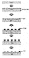
- FIG. 3 is a view illustrating a process of forming a metal pattern on a substrate on which an adhesion promoting layer is formed. Specifically, after forming the first and second adhesion promoter layers on the substrate, after forming a metal layer on the first adhesion promoter layer, forming an etching resist pattern and selectively etching the metal pattern to form a metal pattern The figure shown.
- the manufacturing method provides a method of manufacturing a metal pattern film further comprising the step of peeling the first adhesive layer from a substrate provided with a metal pattern.
- Figure 2 shows the peeling process of the metal pattern film according to the present invention. Specifically, as a process of peeling the first and the second pressure-sensitive adhesive layer from the substrate provided with a metal pattern, it shows a process of peeling the pressure-sensitive adhesive layer and the pattern film by physical force.
- the use of the first and second adhesion promotion layers prevents stick (SICK) -slip (SLIP) phenomenon, thereby preventing damage to the first adhesive layer and the metal pattern substrate, thereby reducing resource recycling and reducing production costs.
- the adhesion promoting layer according to the exemplary embodiment of the present application, the stick (STICK) -slip (SLIP) phenomenon is significantly reduced Metal pattern films could be produced.
- FIG. 1 illustrates a laminated structure of the metal pattern film.
- a method of forming a conductive heating pattern and forming an adhesive layer on a substrate has been used.
- an adhesion promoting layer on the substrate by further including an adhesion promoting layer on the substrate, a stick (STICK) -slip (SLIP) phenomenon may be significantly reduced.
- STICK stick -slip
- the metal pattern films of Examples 2 to 4 were prepared in the same manner as in Example 1, except that the materials shown in Table 1 below were used as the adhesion promoting layer.
- Comparative Examples 1 to 13 The metal pattern of Comparative Examples 1 to 13 was used in the same manner as in Example 1 except for using PET film obtained from film manufacturers shown in Table 1 instead of polyethylene terephthalate (PET), and without using an adhesion promoting layer. A film was produced. Table 1 below is the grade name of the PET film obtained from various film companies.
- the presence of the stick (STICK) / slip (SLIP) phenomenon is determined according to the shape of the visual observation and peel force measurement graph.
- the surface and the peeling surface is a method of measuring the force for peeling at a constant speed while maintaining the vertical and 90 deg.
- Average force according to the Peel strength test was Avg, 90 peel strength (N / cm), the maximum value was expressed as Max, 90 peel strength (N / cm).
- the measured value of the Peel strength test is data that can confirm the adhesion between the substrate and the first adhesive layer and the stick / slip prevention effect, a texture analyzer (TA XT Plus) was used as a measuring device.
- the adhesion promoting layer is ITO as in Example 1, and is a graph measuring peel strength accordingly.
- the shape of the graph is gentler than when the adhesion promoting layer is not applied. This indicates that the sticking (STICK) / slip (SLIP) phenomenon does not occur, and through the strength of the peel strength, The adhesion was also confirmed to increase.
- NiCr of 20 nm or more is generally formed below the metal layer to improve the adhesion between the metal layer and the substrate.
- the adhesion enhancement layer such as NbOx
- the adhesion between the metal layer and the substrate is improved after plating, and in particular, when the Nb 2 Ox is applied alone, the optical properties are the best.
- the cross-cut test was used as a simple method of measuring the adhesion between the thin film formed on the substrate and the substrate, and 100 cells were formed by cutting the thin film 10 times in a 1 mm interval on the surface of the thin film. It is a method of evaluating adhesion between substrates by checking how thin a film is on the substrate when the adhesive tape (usually used ichiban tape) is attached and detached.
- sheet resistance was used as a contact resistance sheet (4-point probe), the transmittance was used COH-400 transmittance meter (D65 / 10).
Landscapes
- Chemical & Material Sciences (AREA)
- Organic Chemistry (AREA)
- Engineering & Computer Science (AREA)
- Mechanical Engineering (AREA)
- Chemical Kinetics & Catalysis (AREA)
- Materials Engineering (AREA)
- Metallurgy (AREA)
- General Chemical & Material Sciences (AREA)
- Health & Medical Sciences (AREA)
- Toxicology (AREA)
- Ceramic Engineering (AREA)
- Laminated Bodies (AREA)
Abstract
Description
| PET 제조사(grade 명) | 부착증진층(nm) | 두께(㎛) | Avg, 90 peel strength(N/cm) | Max, 90 peel strength(N/cm) | Stick/ SLIP | |
| 실시예 1 | Toray(XG7PH2) | ITO(16) | 50 | 15.30 | >20 | X |
| 실시예 2 | Toray(XG7PH2) | SiO2(12) | 50 | >20 | >20 | X |
| 실시예 3 | Toray(XG7PH2) | Al2O3(8) | 50 | 17.95 | >20 | X |
| 실시예 4 | Toray(XG7PH2) | NbOx(5) | 50 | >20 | >20 | X |
| 비교예 1 | SKC(TH34) | X | 20 | 2.45 | 7.1 | O |
| 비교예 2 | Teijin DuPont(KEL86W) | X | 50 | 0.80 | 2.87 | O |
| 비교예 3 | Teijin DuPont(HPE) | X | 38 | 0.25 | 0.53 | O |
| 비교예 4 | Teijin DuPont(G2P2) | X | 38 | 0.16 | 0.25 | O |
| 비교예 5 | Teijin DuPont(G2PZ) | X | 38 | 1.30 | 5.36 | O |
| 비교예 6 | Mitsubishi(O300E188W53B2) | X | 188 | 0.95 | 11.8 | O |
| 비교예 7 | Mitsubishi(T604E50E92) | X | 50 | 0.58 | 3.6 | O |
| 비교예 8 | Mitsubishi(T604E50M12) | X | 50 | 2.30 | 6.8 | O |
| 비교예 9 | Toray(XD592) | X | 75 | 3.79 | 18.0 | O |
| 비교예 10 | Toray(U48) | X | 50 | 2.62 | 13.0 | O |
| 비교예 11 | Toray(XG7PH2) | X | 50 | 4.15 | 15.41 | O |
| 비교예 12 | LGC primer coating PET(전면) | X | 50 | 4.07 | 15.04 | O |
| 비교예 13 | LGC primer coating PET(배면) | X | 50 | 1.90 | 5.27 | O |
| Avg, 90 peel strength(N/cm) | Max, 90 peel strength(N/cm) | Stick/ SLIP | |
| 약품처리 X | >20 | >20 | X |
| 인질초 | >20 | >20 | X |
| 황산과수 | >20 | >20 | X |
| 염화철 | >20 | >20 | X |
| 고객사 PET | 6.12 | 7.13 | X |
| 구분 | 중간층 적용 X | 무기산화물 중간층 | 합금 중간층 | 합금+무기산화물 중간층 | |
| 금속 증착 필름 구조 | PET/Cu | PET/Nb2Ox/Cu | PET/NiCr/Cu | PET/NiCr/Nb2Ox/Cu | |
| 도금 전 | 면저항(Ω/□) | 0.2 | 0.2 | 0.2 | 0.2 |
| 금속층-필름 간 부착력 | OK(5B) | OK(5B) | OK(5B) | OK(5B) | |
| 도금 후 | 면저항(Ω/□) | 0.01 | 0.01 | 0.01 | 0.01 |
| 금속층-필름 간 부착력 | NG | OK(5B) | OK(5B) | OK(5B) | |
| 도금층 제거 후 | 투과도(%) | 90.01 | 88.37 | 86.82 | 83.75 |
| 산란도(%) | 1.09 | 1.55 | 1.12 | 1.21 | |
| 필름-PVB 부착력(90도 PEEL TEST) | NG(~4 N/cm) | OK(>20N/cm) | OK(~15 N/cm) | OK(>20 N/cm) | |
Claims (14)
- 기재;상기 기재의 양면에 각각 구비된 제1 부착증진층 및 제2 부착증진층;상기 제1 부착증진층의 상기 기재에 접하는 면의 반대면에 구비된 금속 패턴;상기 제1 부착증진층의 상기 금속 패턴이 구비된 면 상에 상기 금속 패턴을 덮도록 구비된 제1 점착층; 및상기 제2 부착증진층의 상기 기재에 접하는 면의 반대 면에 구비된 제2 점착층을 포함하며,상기 제1 부착증진층 및 제2 부착증진층은 무기산화물을 포함하는 금속 패턴 필름.
- 청구항 1에 있어서, 상기 제1 및 제2 부착증진층은 네오븀 옥사이드, 산화알루미늄, 산화규소, 산화아연, 산화네오븀, 산화주석, 산화지르코늄 및 산화인듐주석으로 이루어진 군에서 선택되는 1 이상을 포함하는 금속 패턴 필름.
- 청구항 1에 있어서, 상기 제1 및 제2 부착증진층의 각각의 두께는 0.1nm 이상 30nm 이하인 것인 금속 패턴 필름.
- 청구항 1에 있어서, 상기 금속 패턴은 알루미늄, 구리, 니켈, 크롬, 금, 은 및 백금으로 이루어진 군에서 선택되는 1 이상을 포함하는 금속 패턴 필름.
- 청구항 1에 있어서, 상기 금속 패턴의 선고는 10㎛ 이하인 것인 금속 패턴 필름.
- 청구항 1에 있어서, 상기 금속 패턴의 선고의 편차는 20% 이내인 것인 금속 패턴 필름.
- 청구항 1에 있어서, 상기 제1 및 제2 점착층은 PVB(polyvinylbutyral), EVA(ethylene vinyl acetate), PU(polyurethane), 또는 PO(Polyolefin)를 포함하는 것인 금속 패턴 필름.
- 청구항 1에 있어서, 상기 제1 및 제2 점착층은 PVB(polyvinylbutyral)층인 것인 금속 패턴 필름.
- 청구항 1에 있어서, 상기 제1 및 제2 점착층의 각각의 두께는 1㎛ 이상 1000㎛ 이하인 것인 금속 패턴 필름.
- 청구항 1 내지 9 중 어느 한 항에 따른 금속 패턴 필름을 포함하는 접합 유리.
- 기재를 준비하는 단계;상기 기재의 양면에 각각 제1 부착증진층 및 제2 부착증진층을 형성하는 단계;상기 제1 부착증진층의 상기 기재에 접하는 면의 반대면에 금속 패턴을 패터닝하여 금속 패턴을 형성하는 단계;상기 제1 부착증진층의 상기 금속 패턴이 구비된 면 상에 상기 금속 패턴을 덮도록 제1 점착층을 형성하는 단계; 및상기 제2 부착증진층의 상기 기재에 접하는 면의 반대 면에 제2 점착층을 형성하는 단계를 포함하며,상기 제1 부착증진층 및 제2 부착증진층은 무기산화물을 포함하는 것인 청구항 1 내지 9 중 어느 한 항에 따른 금속 패턴 필름의 제조방법.
- 청구항 11에 있어서, 상기 금속 패턴을 형성하는 단계는금속층을 형성하는 단계; 및상기 금속층을 패터닝하여 금속 패턴을 형성하는 단계를 포함하는 것인 금속 패턴 필름의 제조방법.
- 청구항 12에 있어서, 상기 금속층을 패터닝하여 금속 패턴을 형성하는 단계는 상기 금속층 상에 에칭 레지스트 패턴을 형성한 후, 에칭 레지스트 패턴에 의하여 덮여 있지 않은 금속층을 제거함으로써 수행되는 것인 금속 패턴 필름의 제조방법.
- 청구항 11에 있어서, 상기 제1 점착층을 금속 패턴이 구비된 기재로부터 박리 공정하는 단계를 더 포함하는 금속 패턴 필름의 제조방법.
Priority Applications (4)
| Application Number | Priority Date | Filing Date | Title |
|---|---|---|---|
| CN201880036896.5A CN110719842B (zh) | 2017-06-09 | 2018-03-27 | 金属图案膜及其制备方法 |
| JP2019566944A JP6930698B2 (ja) | 2017-06-09 | 2018-03-27 | 金属パターンフィルムおよびその製造方法 |
| EP18812838.3A EP3636430B1 (en) | 2017-06-09 | 2018-03-27 | Metal pattern film and manufacturing method therefor |
| US16/619,763 US11090910B2 (en) | 2017-06-09 | 2018-03-27 | Metal pattern film and manufacturing method therefor |
Applications Claiming Priority (2)
| Application Number | Priority Date | Filing Date | Title |
|---|---|---|---|
| KR10-2017-0072675 | 2017-06-09 | ||
| KR1020170072675A KR102078438B1 (ko) | 2017-06-09 | 2017-06-09 | 금속 패턴 필름 및 이의 제조 방법 |
Publications (1)
| Publication Number | Publication Date |
|---|---|
| WO2018225938A1 true WO2018225938A1 (ko) | 2018-12-13 |
Family
ID=64566509
Family Applications (1)
| Application Number | Title | Priority Date | Filing Date |
|---|---|---|---|
| PCT/KR2018/003607 Ceased WO2018225938A1 (ko) | 2017-06-09 | 2018-03-27 | 금속 패턴 필름 및 이의 제조 방법 |
Country Status (6)
| Country | Link |
|---|---|
| US (1) | US11090910B2 (ko) |
| EP (1) | EP3636430B1 (ko) |
| JP (1) | JP6930698B2 (ko) |
| KR (1) | KR102078438B1 (ko) |
| CN (1) | CN110719842B (ko) |
| WO (1) | WO2018225938A1 (ko) |
Families Citing this family (6)
| Publication number | Priority date | Publication date | Assignee | Title |
|---|---|---|---|---|
| KR102385925B1 (ko) | 2018-11-05 | 2022-04-11 | 주식회사 엘지에너지솔루션 | 전기화학소자용 세퍼레이터 및 이를 포함하는 전기화학소자 |
| CN113728255B (zh) | 2019-03-28 | 2024-11-01 | 维特罗平板玻璃有限责任公司 | 可加热的风挡 |
| EP3972832A4 (en) * | 2019-05-23 | 2023-06-28 | Saint-Gobain Performance Plastics Corporation | Solar control film |
| CA3167821A1 (en) | 2020-02-14 | 2021-08-19 | Zhixun MA | Low sheet resistance coating |
| KR102838164B1 (ko) | 2022-06-09 | 2025-07-24 | 에스케이이노베이션 주식회사 | 분리막, 이의 제조방법 및 상기 분리막을 포함하는 전기화학소자 |
| CN115474302A (zh) * | 2022-10-14 | 2022-12-13 | 广东省载诚新材料有限公司 | 一种玻璃加热膜片制作方法、玻璃加热膜片及装置 |
Citations (6)
| Publication number | Priority date | Publication date | Assignee | Title |
|---|---|---|---|---|
| JP2008260227A (ja) * | 2007-04-12 | 2008-10-30 | Toyo Ink Mfg Co Ltd | 金属パターン部材 |
| KR20120012568A (ko) * | 2010-08-02 | 2012-02-10 | 송원호 | 유리막이 형성된 프로브판, 그의 유리막이 형성된 프로브판 제조방법 |
| JP2016020145A (ja) * | 2014-07-14 | 2016-02-04 | 大日本印刷株式会社 | 合わせガラス、メッシュシート及び合わせガラス用中間部材 |
| JP2016044096A (ja) * | 2014-08-21 | 2016-04-04 | 大日本印刷株式会社 | 合わせガラス、乗り物および窓 |
| JP2016120894A (ja) * | 2014-12-25 | 2016-07-07 | 大日本印刷株式会社 | 発熱板及び乗り物 |
| KR20170072675A (ko) | 2015-12-17 | 2017-06-27 | 엘지전자 주식회사 | 디스플레이 디바이스 |
Family Cites Families (21)
| Publication number | Priority date | Publication date | Assignee | Title |
|---|---|---|---|---|
| JP2002348151A (ja) * | 2001-05-25 | 2002-12-04 | Nippon Sheet Glass Co Ltd | 熱線反射合わせウインドシールドガラス |
| JP4203237B2 (ja) * | 2001-11-15 | 2008-12-24 | 三菱樹脂株式会社 | 透明ガスバリヤー性フィルム積層板及び透明積層体 |
| US7838102B2 (en) | 2004-10-28 | 2010-11-23 | E. I. Du Pont De Nemours And Company | Filled polyvinyl butyral sheeting for decorative laminated glass and a process for making same |
| JP5401132B2 (ja) | 2009-01-20 | 2014-01-29 | 信越ポリマー株式会社 | 電波透過性装飾部材およびその製造方法 |
| JP5120661B2 (ja) | 2009-03-26 | 2013-01-16 | 住友金属鉱山株式会社 | 合わせ構造体 |
| JP2012126578A (ja) | 2009-04-13 | 2012-07-05 | Asahi Glass Co Ltd | 自動車ガラス用積層体、その製造方法、およびフロントガラス |
| WO2011017039A2 (en) * | 2009-08-03 | 2011-02-10 | 3M Innovative Properties Company | Antireflective transparent emi shielding optical filter |
| JP5585143B2 (ja) * | 2010-03-18 | 2014-09-10 | 凸版印刷株式会社 | 透明導電性積層体およびその製造方法ならびにタッチパネル |
| JP5822132B2 (ja) * | 2011-12-16 | 2015-11-24 | 大日本印刷株式会社 | 積層体および導電パターンフィルム製造方法 |
| KR101707042B1 (ko) * | 2013-06-19 | 2017-02-17 | 일진머티리얼즈 주식회사 | 도전성 방열(放熱)시트, 이를 포함하는 전기부품 및 전자제품 |
| JP6295551B2 (ja) * | 2013-09-03 | 2018-03-20 | 凸版印刷株式会社 | 透明導電性積層体、タッチパネル、および、透明導電性積層体の製造方法 |
| TWI629914B (zh) | 2013-11-29 | 2018-07-11 | Lg化學股份有限公司 | 加熱元件及其製造方法以及車輛用窗 |
| KR101549987B1 (ko) | 2013-12-23 | 2015-09-03 | (주)창성 | 열전도성 접착층을 이용하며, 흑연층을 포함하는 방열기능이 향상된 복합 필름 및 그 제조 방법. |
| US20150202846A1 (en) | 2014-01-17 | 2015-07-23 | Pleotint, L.L.C. | Reflective and conductive coatings directly on pvb |
| US9128663B1 (en) * | 2014-08-04 | 2015-09-08 | T-Kingdom Co., Ltd. | Touch sensing electrode structure and method of manufacturing same |
| JP2016102055A (ja) | 2014-11-17 | 2016-06-02 | 大日本印刷株式会社 | 合わせガラス、パターンシート及び合わせガラスの製造方法 |
| US10912155B2 (en) | 2014-11-17 | 2021-02-02 | Dai Nippon Printing Co., Ltd. | Heating plate, conductive pattern sheet, vehicle, and method of manufacturing heating plate |
| KR20160079296A (ko) | 2014-12-26 | 2016-07-06 | 주식회사 엘지화학 | 광경화성 안료 분산액 및 이를 이용한 광경화성 잉크 조성물 |
| KR20150116767A (ko) | 2015-01-06 | 2015-10-16 | 존스미디어 주식회사 | 장식 필름이 부착된 창유리 |
| JP6060223B1 (ja) * | 2015-07-22 | 2017-01-11 | 日東電工株式会社 | 透明な粘着剤層を有するカバー部材 |
| KR101718780B1 (ko) | 2016-06-24 | 2017-03-24 | 현대안전유리공업(주) | 접합유리 제조방법 |
-
2017
- 2017-06-09 KR KR1020170072675A patent/KR102078438B1/ko active Active
-
2018
- 2018-03-27 JP JP2019566944A patent/JP6930698B2/ja active Active
- 2018-03-27 US US16/619,763 patent/US11090910B2/en active Active
- 2018-03-27 CN CN201880036896.5A patent/CN110719842B/zh active Active
- 2018-03-27 EP EP18812838.3A patent/EP3636430B1/en active Active
- 2018-03-27 WO PCT/KR2018/003607 patent/WO2018225938A1/ko not_active Ceased
Patent Citations (6)
| Publication number | Priority date | Publication date | Assignee | Title |
|---|---|---|---|---|
| JP2008260227A (ja) * | 2007-04-12 | 2008-10-30 | Toyo Ink Mfg Co Ltd | 金属パターン部材 |
| KR20120012568A (ko) * | 2010-08-02 | 2012-02-10 | 송원호 | 유리막이 형성된 프로브판, 그의 유리막이 형성된 프로브판 제조방법 |
| JP2016020145A (ja) * | 2014-07-14 | 2016-02-04 | 大日本印刷株式会社 | 合わせガラス、メッシュシート及び合わせガラス用中間部材 |
| JP2016044096A (ja) * | 2014-08-21 | 2016-04-04 | 大日本印刷株式会社 | 合わせガラス、乗り物および窓 |
| JP2016120894A (ja) * | 2014-12-25 | 2016-07-07 | 大日本印刷株式会社 | 発熱板及び乗り物 |
| KR20170072675A (ko) | 2015-12-17 | 2017-06-27 | 엘지전자 주식회사 | 디스플레이 디바이스 |
Non-Patent Citations (1)
| Title |
|---|
| See also references of EP3636430A4 |
Also Published As
| Publication number | Publication date |
|---|---|
| EP3636430B1 (en) | 2026-01-21 |
| JP6930698B2 (ja) | 2021-09-01 |
| EP3636430A4 (en) | 2020-04-29 |
| EP3636430A1 (en) | 2020-04-15 |
| KR20180134654A (ko) | 2018-12-19 |
| US11090910B2 (en) | 2021-08-17 |
| CN110719842A (zh) | 2020-01-21 |
| US20200101700A1 (en) | 2020-04-02 |
| JP2020522407A (ja) | 2020-07-30 |
| CN110719842B (zh) | 2021-08-24 |
| KR102078438B1 (ko) | 2020-02-17 |
Similar Documents
| Publication | Publication Date | Title |
|---|---|---|
| WO2018225938A1 (ko) | 금속 패턴 필름 및 이의 제조 방법 | |
| WO2012036527A2 (ko) | 시인성이 우수한 투명 전도성 필름 및 그 제조 방법 | |
| CN109641419B (zh) | 层叠体、电子设备的制造方法、层叠体的制造方法 | |
| US11981835B2 (en) | Interlayer filler material for touch panels, and laminate | |
| WO2012008683A2 (ko) | 플렉서블 전자소자의 제조방법, 플렉서블 전자소자 및 플렉서블 기판 | |
| WO2015076505A1 (ko) | 복합 편광판 일체형 터치 감지 전극 및 이를 구비한 터치 스크린 패널 | |
| WO2018030712A1 (ko) | 포토레지스트 음각패턴 및 표면개질을 이용한 금속메쉬 타입 투명 전도막 제조방법 및 이에 의해 제조되는 투명 전도막 | |
| WO2014189204A1 (ko) | 투명 전극 패턴 적층체 및 이를 구비한 터치 스크린 패널 | |
| WO2017006801A1 (ja) | キャリア基板、積層体、電子デバイスの製造方法 | |
| US11812524B2 (en) | Heating film and method for manufacturing same | |
| WO2020040518A1 (ko) | 투명 발광소자 디스플레이용 매립형 전극 기판 및 이의 제조방법 | |
| US20200043951A1 (en) | Electronic assemblies incorporating laminate substrates and methods of fabricating the same | |
| WO2014157841A1 (ko) | 투명 전극 패턴 적층체 및 이를 구비한 터치 스크린 패널 | |
| WO2017131202A1 (ja) | 導電性積層フィルム | |
| WO2019168303A1 (ko) | 터치센서 일체형 디지타이저 및 이를 포함하는 표시 장치 | |
| WO2013103259A1 (ko) | 시인성이 우수한 양면 투명 전도성 필름 및 그 제조 방법 | |
| US10104770B2 (en) | Touch panel, preparing method thereof, and Ag—Pd—Nd alloy for touch panel | |
| KR101554847B1 (ko) | 적층 필름 및 그 필름 롤, 그리고 그것으로부터 얻어질 수 있는 광투과성 도전성 필름 및 그것을 이용한 터치 패널 | |
| WO2016186394A1 (ko) | 전도성 적층체 및 이를 포함하는 투명 전극 | |
| WO2015152603A1 (ko) | 폴리에스테르 필름 및 이를 이용한 투명전극 필름 | |
| WO2011111929A2 (ko) | 터치패널용 패드의 제조방법 및 이에 의해 제조되는 터치패널용 패드 | |
| JPH07287218A (ja) | 透明導電性基板およびそれを用いた表示装置 | |
| CN116323178A (zh) | 玻璃层叠体及其制造方法 | |
| WO2019112316A1 (ko) | 발열필름 및 이의 제조방법 | |
| WO2019190256A1 (ko) | 고성능 필름형 터치센서 |
Legal Events
| Date | Code | Title | Description |
|---|---|---|---|
| 121 | Ep: the epo has been informed by wipo that ep was designated in this application |
Ref document number: 18812838 Country of ref document: EP Kind code of ref document: A1 |
|
| ENP | Entry into the national phase |
Ref document number: 2019566944 Country of ref document: JP Kind code of ref document: A |
|
| NENP | Non-entry into the national phase |
Ref country code: DE |
|
| WWE | Wipo information: entry into national phase |
Ref document number: 2018812838 Country of ref document: EP |
|
| ENP | Entry into the national phase |
Ref document number: 2018812838 Country of ref document: EP Effective date: 20200109 |
|
| WWG | Wipo information: grant in national office |
Ref document number: 2018812838 Country of ref document: EP |