WO2018229943A1 - 送信装置、受信装置および無線通信システム - Google Patents
送信装置、受信装置および無線通信システム Download PDFInfo
- Publication number
- WO2018229943A1 WO2018229943A1 PCT/JP2017/022153 JP2017022153W WO2018229943A1 WO 2018229943 A1 WO2018229943 A1 WO 2018229943A1 JP 2017022153 W JP2017022153 W JP 2017022153W WO 2018229943 A1 WO2018229943 A1 WO 2018229943A1
- Authority
- WO
- WIPO (PCT)
- Prior art keywords
- transmission
- unit
- signal
- interference
- block
- Prior art date
- Legal status (The legal status is an assumption and is not a legal conclusion. Google has not performed a legal analysis and makes no representation as to the accuracy of the status listed.)
- Ceased
Links
Images




Classifications
-
- H—ELECTRICITY
- H04—ELECTRIC COMMUNICATION TECHNIQUE
- H04L—TRANSMISSION OF DIGITAL INFORMATION, e.g. TELEGRAPHIC COMMUNICATION
- H04L1/00—Arrangements for detecting or preventing errors in the information received
- H04L1/02—Arrangements for detecting or preventing errors in the information received by diversity reception
- H04L1/06—Arrangements for detecting or preventing errors in the information received by diversity reception using space diversity
- H04L1/0618—Space-time coding
- H04L1/0637—Properties of the code
- H04L1/0643—Properties of the code block codes
-
- H—ELECTRICITY
- H04—ELECTRIC COMMUNICATION TECHNIQUE
- H04B—TRANSMISSION
- H04B7/00—Radio transmission systems, i.e. using radiation field
- H04B7/02—Diversity systems; Multi-antenna system, i.e. transmission or reception using multiple antennas
- H04B7/022—Site diversity; Macro-diversity
- H04B7/024—Co-operative use of antennas of several sites, e.g. in co-ordinated multipoint or co-operative multiple-input multiple-output [MIMO] systems
-
- H—ELECTRICITY
- H04—ELECTRIC COMMUNICATION TECHNIQUE
- H04B—TRANSMISSION
- H04B7/00—Radio transmission systems, i.e. using radiation field
- H04B7/02—Diversity systems; Multi-antenna system, i.e. transmission or reception using multiple antennas
- H04B7/04—Diversity systems; Multi-antenna system, i.e. transmission or reception using multiple antennas using two or more spaced independent antennas
- H04B7/06—Diversity systems; Multi-antenna system, i.e. transmission or reception using multiple antennas using two or more spaced independent antennas at the transmitting station
- H04B7/0613—Diversity systems; Multi-antenna system, i.e. transmission or reception using multiple antennas using two or more spaced independent antennas at the transmitting station using simultaneous transmission
- H04B7/0615—Diversity systems; Multi-antenna system, i.e. transmission or reception using multiple antennas using two or more spaced independent antennas at the transmitting station using simultaneous transmission of weighted versions of same signal
-
- H—ELECTRICITY
- H04—ELECTRIC COMMUNICATION TECHNIQUE
- H04B—TRANSMISSION
- H04B7/00—Radio transmission systems, i.e. using radiation field
- H04B7/02—Diversity systems; Multi-antenna system, i.e. transmission or reception using multiple antennas
- H04B7/04—Diversity systems; Multi-antenna system, i.e. transmission or reception using multiple antennas using two or more spaced independent antennas
- H04B7/08—Diversity systems; Multi-antenna system, i.e. transmission or reception using multiple antennas using two or more spaced independent antennas at the receiving station
- H04B7/0837—Diversity systems; Multi-antenna system, i.e. transmission or reception using multiple antennas using two or more spaced independent antennas at the receiving station using pre-detection combining
- H04B7/0842—Weighted combining
- H04B7/0848—Joint weighting
- H04B7/0854—Joint weighting using error minimizing algorithms, e.g. minimum mean squared error [MMSE], "cross-correlation" or matrix inversion
-
- H—ELECTRICITY
- H04—ELECTRIC COMMUNICATION TECHNIQUE
- H04J—MULTIPLEX COMMUNICATION
- H04J13/00—Code division multiplex systems
- H04J13/16—Code allocation
- H04J13/18—Allocation of orthogonal codes
-
- H—ELECTRICITY
- H04—ELECTRIC COMMUNICATION TECHNIQUE
- H04L—TRANSMISSION OF DIGITAL INFORMATION, e.g. TELEGRAPHIC COMMUNICATION
- H04L1/00—Arrangements for detecting or preventing errors in the information received
- H04L1/02—Arrangements for detecting or preventing errors in the information received by diversity reception
- H04L1/06—Arrangements for detecting or preventing errors in the information received by diversity reception using space diversity
Definitions
- the present invention relates to a transmission device that transmits a space-time-encoded signal, a reception device that receives a signal transmitted from the transmission device, and a wireless communication system including the transmission device.
- Non-Patent Document 1 discloses a transmission method in which differential space-time coding is performed for each of two phase-modulated symbols, and a signal subjected to differential space-time coding is transmitted using two transmission antennas, and the signal And a reception method when receiving the message.
- the entire service area is covered by arranging a plurality of base stations.
- a range in which a mobile station can communicate with one base station is referred to as a communication area.
- a mobile station moving in the service area performs communication while switching a base station to be a communication partner.
- Each base station is installed such that communication areas of adjacent base stations overlap each other so that communication is not interrupted even when the mobile station moves over a plurality of communication areas.
- interference suppression processing As a method for solving this problem, there is a method in which a mobile station performs processing called interference suppression processing in which the influence of interference signals is removed.
- the interference suppression process is a process of estimating an interference signal received by the mobile station and removing the estimated interference signal from the received signal.
- the conventional radio communication system using differential space-time coding has a problem that the mobile station does not perform transmission path estimation and cannot perform interference suppression processing.
- the present invention has been made to solve the above-described problems, and provides a transmission apparatus capable of suppressing the influence of an interference signal in a reception apparatus in a wireless communication system using differential space-time coding. With the goal.
- a transmission apparatus provides a space-time coding unit that generates a transmission block by space-time coding a transmission symbol, and a difference from the transmission block.
- a differential unit that performs dynamic processing, and a code multiplication unit that multiplies the transmission block by a code.
- the transmission apparatus further includes a selection unit that selects one of the transmission block after differential processing and the transmission block after code multiplication, and a transmission unit that transmits the selected transmission block.
- the transmission apparatus has an effect that the influence of an interference signal in the reception apparatus can be suppressed in a wireless communication system using differential space-time coding.
- wireless communications system concerning Embodiment The figure which shows an example of the frame format of the frame used by the downlink communication of a radio
- the figure which shows the structural example of a base station The flowchart which shows an example of the transmission processing procedure in the base station of embodiment
- the figure which shows the structural example of a processing circuit The figure which shows the structural example of the processing circuit provided with a processor
- the figure which shows the structural example of a mobile station The figure which shows the structural example of an interference suppression part.
- FIG. 1 is a diagram illustrating a configuration example of a wireless communication system according to an embodiment of the present invention.
- a radio communication system 10 according to the present embodiment includes base stations 1-1 and 1-2, a mobile station 3, and a control station 4.
- the base station 1-1 forms a communication area 2-1
- the base station 1-2 forms a communication area 2-2.
- the communication area 2-1 is a range in which the mobile station 3 can receive a signal transmitted from the base station 1-1.
- the communication area 2-2 is a range in which the mobile station 3 can receive a signal transmitted from the base station 1-2.
- the communication area 2-1 and the communication area 2-2 partially overlap.
- the base stations 1-1 and 1-2 are shown without being individually distinguished, they are referred to as the base station 1, and when the communication areas 2-1 and 2-2 are shown without being individually distinguished, the communication area 2 It describes.
- the base station 1 has a plurality of antennas, and can transmit radio signals to the mobile station 3 through the plurality of antennas.
- the control station 4 is connected to each base station 1 by wire and controls each base station 1. Note that the control station 4 and the base station 1 may be wirelessly connected. Each base station 1 wirelessly transmits a control signal including information necessary for wireless connection with the mobile station 3 under the control of the control station 4.
- the mobile station 3 enters the communication area 2 of the base station 1, the mobile station 3 receives the control signal transmitted from the base station 1 forming the communication area 2, and wirelessly connects to the base station 1 based on the control signal.
- the connection process for performing is performed. Thereafter, the mobile station 3 can perform wireless communication with the base station 1.
- the control performed by the control station 4 on each base station 1 is control for operation of the radio communication system 10, and the control content is not particularly limited.
- the control station 4 gives an instruction regarding a signal transmitted from each base station 1.
- data transmitted from each base station 1 is transmitted to the base station 1, and parameters or the like in processing to be described later performed by each base station 1 is instructed.
- An example of the parameter is a code and a modulation method in the modulation process described later.
- the wireless communication system 10 includes a plurality of base stations 1 in order to form a service area along a trajectory or a service area extending in a plurality of directions on the ground surface.
- the wireless communication system 10 includes three or more base stations 1 and forms a service area along the trajectory, a communication area of a base station not shown on the right side of the base station 1-2 in FIG. Are arranged so as to overlap the communication area 2-2.
- the service areas along the trajectory are formed by arranging the base stations so that the communication areas of the adjacent base stations overlap.
- the radio communication system 10 forms a service area extending in a plurality of directions on the ground surface, for example, in FIG. 1, at least one of the upper, lower, diagonally upper, and diagonally lower base stations 1-1.
- a communication area of a base station (not shown) is arranged in one direction so as to overlap with the communication area 2-1.
- the base station 1 is a transmitting device and the mobile station 3 is a receiving device. Any configuration and operation may be used for the configuration and operation related to uplink communication that is communication in the direction from the mobile station 3 to the base station 1. Further, the mobile station 3 and the base station 1 may not have a function of performing uplink communication.
- FIG. 2 is a diagram illustrating an example of a frame format of a frame used in downlink communication of the wireless communication system 10 according to the present embodiment.
- the frame used in the downlink communication of the wireless communication system 10 according to the present embodiment includes an interference measurement signal, a synchronization signal, and a data signal.
- the interference measurement signal is used in the mobile station 3 to measure an interference signal that is a reception signal that becomes an interference component. The measurement of the interference signal will be described later.
- the synchronization signal is used in the mobile station 3 for frame synchronization.
- Frame synchronization is a process for detecting the beginning of a frame or a predetermined position within the frame. For example, a predetermined bit string or the like is used as the synchronization signal.
- the synchronization signal may be any synchronization signal.
- the data signal is information transmitted from the base station 1 to the mobile station 3.
- the frame format shown in FIG. 2 is an example, and the arrangement order of the interference measurement signal, the synchronization signal, and the data signal is not limited to the example shown in FIG.
- the base station 1 performs differential space-time coding on the synchronization signal and the data signal, and space-time coding on the interference measurement signal.
- the mobile station 3 that has received the signal transmitted from the base station 1 does not need to perform transmission path estimation in decoding of the data signal, and transmits using the received interference measurement signal. Since path estimation can be performed, interference suppression processing can be performed.
- Interference measurement signal is composed of one or more blocks.
- the block is data serving as a unit in which processing of space-time coding and differential space-time coding is performed.
- one block is composed of the same number of symbols as the number of transmission antennas. For example, when the number of transmission antennas is 2, 2 symbols are set as 1 block.
- a symbol is a chunk of data of 1 bit or more.
- modulation is performed before space-time coding and differential space-time coding, a symbol is data serving as a unit of modulation, that is, a modulation symbol.
- a modulation method in units of 2 bits such as QPSK (Quadrature Phase Shift Keying)
- QPSK Quadrature Phase Shift Keying
- one symbol is 2 bits
- modulation in units of 1 bit is performed like BPSK (Binary Phase Shift Keying).
- BPSK Binary Phase Shift Keying
- FIG. 3 is a diagram illustrating a configuration example of an interference measurement signal according to the present embodiment.
- the interference measurement signal in one frame is composed of eight blocks.
- the blocks constituting the interference measurement signal are also referred to as interference measurement blocks.
- the interference measurement block is composed of interference measurement bits. Arbitrary data can be used as the interference measurement bit.
- FIG. 3 shows an example in which four types of interference measurement blocks b1, b2, b3, and b4 are transmitted twice. That is, two identical interference measurement blocks are transmitted in succession.
- the number of interference measurement blocks constituting the interference measurement signal in one frame is not limited to 8, and the number of interference measurement blocks can be any number. Further, the number of times the same interference measurement block is transmitted is not limited to two, and can be any number.
- 8 interference measurement blocks in one frame are multiplied by a code.
- This code is a code different between the base stations 1. That is, this code is determined for each transmission device. Note that it is not necessary to use different codes for all the base stations 1, and different codes may be used for the base stations 1 such as the adjacent base stations 1 that may cause interference with each other. Thereby, the mobile station 3 can identify the interference measurement signal received from each base station 1. It is desirable that the codes used in the base stations 1 that may cause interference with each other are orthogonal to each other.
- each block is multiplied by codes orthogonal to each other between base stations that interfere with each other.
- the code e k that the base station 1-1 multiplies the interference measurement signal is “+1, +1, +1, +1, +1, +1, +1, +1”, and the base station 1-2 interferes.
- the code f k to be multiplied with the measurement signal is “+1, ⁇ 1, +1, ⁇ 1, +1, ⁇ 1, +1, ⁇ 1”.
- the code e k and the code f k are codes orthogonal to each other. Note that symbols corresponding to the k-th block are denoted as e k and f k , respectively.
- FIG. 4 is a diagram illustrating a configuration example of the base station 1 according to the present embodiment.
- the base station 1 which is a transmission apparatus in downlink communication includes a frame generation unit 101, a mapping unit 102, a space-time encoding unit 103, a differential unit 104, a delay unit 105, a code multiplication unit 106, a selection unit Unit 107, transmission signal division unit 108, waveform shaping units 109a and 109b, radio transmission units 110a and 110b, transmission antennas 111a and 111b, and transmission control unit 112.
- the solid line indicates the path of data to be transmitted
- the broken line indicates the path of the instruction signal instructed from the transmission control unit 112.
- FIG. 5 is a flowchart showing an example of a transmission processing procedure in the base station 1 of the present embodiment.
- the operation of base station 1 of the present embodiment will be described using FIG. 4 and FIG. FIG. 5 shows a transmission processing procedure for one frame.
- Any method may be used as a method of synchronizing the transmission timing between the base stations 1.
- the control station 4 instructs each base station 1 of the transmission timing.
- a method of synchronizing the transmission timing by performing time synchronization using GPS (Global Positioning System) one base station 1 becomes a reference, and another base station 1 communicates with the base station 1 by wireless communication or wired communication.
- GPS Global Positioning System
- the frame generation unit 101 of the base station 1 transmits an interference measurement bit that is data transmitted as an interference measurement signal, a synchronization bit that is data transmitted as a synchronization signal, and a data signal.
- Data bits that are data to be output are output to the mapping unit 102 based on an instruction from the transmission control unit 112 (step S1).
- the transmission control unit 112 instructs the frame generation unit 101 to output the respective bits so that the interference measurement bits, the synchronization bits, and the data bits are output from the frame generation unit 101 in the order according to the frame format.
- the interference measurement bits, data bits, and synchronization bits may be input from the transmission control unit 112 to the frame generation unit 101, or may be generated by a data generation unit (not shown) and input to the frame generation unit 101. May be transmitted from the control station 4.
- the mapping unit 102 maps the bits output from the frame generation unit 101 to symbols represented by complex numbers, and outputs the transmission symbols that are mapped symbols to the space-time encoding unit 103 (step S2). That is, mapping section 102 modulates the bits output from frame generation section 101 to generate a transmission symbol and outputs it to space-time encoding section 103. Any mapping method may be used as the mapping method performed by the mapping unit 102. For example, a mapping method according to QPSK can be used.
- FIG. 6 is a diagram illustrating an example of mapping by QPSK.
- the horizontal axis indicates the I axis indicating the real part of the complex number
- the vertical axis indicates the Q axis indicating the imaginary part of the complex number.
- 2 bits are mapped to four signal points on the circumference of a unit circle. Specifically, bit “00” is set to the point of ⁇ / 4 [rad], bit “01” is set to the point of 3 ⁇ / 4 [rad], and bit “11” is set to the point of 5 ⁇ / 4 [rad]. Bit “10” is mapped to a point of 7 ⁇ / 4 [rad].
- the angle of the signal point on the IQ plane described above is an angle from the I axis.
- the space-time coding unit 103 performs space-time coding processing on a transmission symbol that is a symbol output from the mapping unit 102 (step S ⁇ b> 3). Specifically, the space-time coding unit 103 sets the number of symbols equal to the number of transmission antennas as one block, generates a matrix for each block, that is, a transmission block, and outputs the matrix to the differential unit 104 and the code multiplication unit 106. . That is, the space-time coding unit 103 generates a transmission block by space-time coding the transmission symbol. In the following, as shown in FIG.
- the matrix S (bold) k generated by the space-time coding unit 103 is expressed as follows when the two symbols constituting the k-th block (k is an integer of 0 or more) are s k, 1 and s k, 2 respectively. (1).
- the differential unit 104 performs differential processing using the matrix S (bold) k output from the space-time encoding unit 103 and the matrix C (bold) k ⁇ 1 output from the delay unit 105 ( Step S5).
- the differential unit 104 performs differential processing on the transmission block. Specifically, the differential unit 104 multiplies the matrix S (bold) k and the matrix C (bold) k ⁇ 1 by multiplying the matrix C (bold) k as shown in the following equation (2). Is output to the selection unit 107 and the delay unit 105.
- the matrix C (bold) k ⁇ 1 is a matrix generated by the processing of the differential unit 104 for the previous block, that is, the k ⁇ 1th block.
- the delay unit 105 holds the matrix C (bold) k input from the differential unit 104 and outputs it to the differential unit 104 when processing the next block.
- the code multiplier 106 multiplies the matrix S (bold) k output from the space-time encoder 103 by a code (step S4). That is, the code multiplication unit 106 multiplies the transmission block by a code.
- the code by which the code multiplier 106 multiplies the matrix S (bold) k is a code determined for each base station 1 as described in the description with reference to FIG.
- the code by which the code multiplication unit 106 multiplies the matrix S (bold) k is instructed by the transmission control unit 112.
- the code used for each base station 1 may be set in advance in the transmission control unit 112 of each base station 1, or may be instructed by the control station 4 and held in the transmission control unit 112.
- code multiplication section 106 of the base station 1-1 has the following formula (3) as shown in the code e k matrix S (bold) k 'generates k, the matrix C (bold)' matrix C (bold) by multiplying k to the selector 107.
- the transmission control unit 112 determines whether or not it is the transmission period of the interference measurement signal based on the frame format (step S6). When it is the transmission period of the interference measurement signal (Yes in step S6), the transmission control unit 112 instructs the selection unit 107 to select the differential processing result, that is, the matrix C (bold) k (step S7).
- the selection unit 107 selects the matrix C (bold) k output from the differential unit 104 according to an instruction from the transmission control unit 112 and outputs the matrix C to the transmission signal division unit 108.
- the transmission control unit 112 sends the code multiplication result, that is, the matrix C (bold) to the selection unit 107. 'Instruct to select k (step S8).
- selection section 107 selects matrix C (bold) ' k output from code multiplication section 106 and outputs the selected matrix C to transmission signal division section 108. That is, the selection unit 107 selects one of the transmission block after differential processing and the transmission block after code multiplication.
- the base station 1 transmits the matrix output from the selection unit 107 as a radio signal (step S9).
- the transmission signal division unit 108 divides the signal input from the selection unit 107 into two signals respectively corresponding to the transmission antennas 111a and 111b.
- the transmission signal division unit 108 outputs the two symbols in the first column of the matrix output from the selection unit 107 to the waveform shaping unit 109a corresponding to the transmission antenna 111a, and the matrix output from the selection unit 107.
- the transmission signal dividing unit 108 may not be provided.
- the transmission signal division unit 108 outputs c k, 1 and ⁇ c * k, 2 to the waveform shaping unit 109a, and c k , 2 and c * k, 1 are output to the waveform shaping unit 109b.
- the waveform shaping sections 109a and 109b perform waveform shaping on the input signals using, for example, a root Nyquist filter, and output the waveform-shaped signals to the wireless transmission sections 110a and 110b, respectively.
- the processing in the waveform shaping units 109a and 109b is not limited to waveform shaping by the root Nyquist filter, and general arbitrary waveform shaping processing can be used.
- the waveform shaping units 109a and 109b may be part of the wireless transmission units 110a and 110b, respectively.
- Radio transmission sections 110a and 110b perform DA (Digital to Analog) conversion, up-conversion, amplification, and the like on the signals output from waveform shaping sections 109a and 109b, respectively, and transmit the processed signals to transmission antenna 111a. , 111b, respectively.
- the wireless transmission unit 110 a and the wireless transmission unit 110 b are transmission units that transmit the transmission block selected by the selection unit 107. Note that the processing in the wireless transmission units 110a and 110b is not limited to the above-described example, and may be arbitrary processing generally performed as transmission processing in wireless communication.
- step S9 the transmission control unit 112 determines whether transmission of one frame is completed (step S10), and when transmission of one frame is completed (Yes in step S10), the process is terminated. If transmission of one frame has not been completed (No at Step S10), the transmission control unit 112 controls to perform the processing from Step S1 again. At this time, in step S1, the transmission control unit 112 instructs the frame generation unit 101 to output the bits of the next block. Through the above processing, the processing from step S1 to step S9 is performed for each block.
- the matrix output from space-time encoding section 103 is input to differential section 104 and code multiplication section 106, but transmission control section 112 performs space-time code according to the frame format.
- the output destination of the matrix may be designated to the conversion unit 103. That is, when the transmission control unit 112 outputs the interference measurement bit from the frame generation unit 101, the output destination is the code multiplication unit 106, and when the synchronization bit or the data bit is output from the frame generation unit 101
- the space-time encoding unit 103 may be instructed to set the output destination to the differential unit 104.
- the transmission antennas 111a and 111b constituting the base station 1 of the present embodiment are antennas, and the wireless transmission units 110a and 110b are transmitters.
- Each unit 112 is realized by a processing circuit.
- FIG. 7 is a diagram illustrating a configuration example of a processing circuit.
- the processing circuit 500 shown in FIG. 7 is a processing circuit configured as a dedicated circuit.
- the processing circuit 500 includes, for example, an ASIC (Application Specific Integrated Circuit), an FPGA (Field Programmable Gate Array), or a combination thereof.
- FIG. 8 is a diagram illustrating a configuration example of a processing circuit 600 including a processor.
- a processing circuit 600 illustrated in FIG. 8 includes a processor 601 and a memory 602.
- the processor 601 corresponds to a CPU (Central Processing Unit), a microprocessor, or the like.
- the memory 602 corresponds to a nonvolatile or volatile semiconductor memory such as a RAM (Random Access Memory), a ROM (Read Only Memory), a flash memory, or a magnetic disk.
- Frame generation unit 101 mapping unit 102, space-time encoding unit 103, differential unit 104, delay unit 105, code multiplication unit 106, selection unit 107, transmission signal division unit 108, waveform shaping units 109a and 109b, and transmission control unit
- the processing circuit realizing 112 is realized by the processing circuit 600 illustrated in FIG. 8, the functions of the respective units are realized by the processor 601 executing a program stored in the memory 602.
- the memory 602 is also used as a storage area when a program is executed by the processor 601.
- the control unit 112 may be realized by the processing circuit 500 partly configured as a dedicated circuit, and the remaining part may be realized by the processing circuit 600 including the processor 601.
- FIG. 9 is a diagram illustrating a configuration example of the mobile station 3 according to the present embodiment.
- the mobile station 3 includes receiving antennas 201a and 201b, radio receiving units 202a and 202b, waveform shaping units 203a and 203b, an interference suppressing unit 204, differential space-time decoding units 205a and 205b, and a combining unit 206.
- the mobile station 3 is a receiving device that can receive signals transmitted from a plurality of base stations 1.
- the reception antennas 201a and 201b are an example of a plurality of reception antennas that receive reception signals including signals transmitted from the plurality of base stations 1.
- the number of receiving antennas is not limited to two.
- the communication partner of the mobile station 3 is the base station 1-1
- the radio signal transmitted from the base station 1-1 is the desired signal
- the radio signal transmitted from the base station 1-2 Will be described as an interference signal.
- the radio receiving units 202a and 202b perform amplification, down-conversion, AD (Analog to Digital) conversion, and the like on the signals received by the receiving antennas 201a and 201b, respectively, and waveform-shape the processed signals.
- the data is output to the sections 203a and 203b. Note that the processing in the wireless reception units 202a and 202b is not limited to these, and may be general reception processing.
- the waveform shaping sections 203a and 203b remove the signal components outside the band of the desired signal and perform waveform shaping on the desired signal, for example, by a root Nyquist filter, for the signals output from the wireless receiving sections 202a and 202b, respectively.
- the waveform shaping process performed by the waveform shaping units 203a and 203b is not limited to the process using the root Nyquist filter.
- the interference suppression unit 204 performs interference suppression processing.
- ZF Zero Forcing
- MMSE Minimum Mean Square Error
- FIG. 10 is a diagram illustrating a configuration example of the interference suppression unit 204.
- the interference suppression unit 204 includes transmission path estimation units 301a and 301b, a weight calculation unit 302, and an interference removal unit 303.
- the operation timing of the interference suppression unit 204 is controlled by the reception control unit 209.
- the reception control unit 209 performs processing of the transmission path estimation units 301a and 301b and the weight calculation unit 302 in a period in which the interference measurement signal is received, and processing of the interference removal unit 303 performs synchronization signals and data signals. Each unit is controlled so as to be performed during the reception period.
- the transmission path estimation units 301a and 301b perform transmission path estimation of interference signals included in signals received by the reception antennas 201a and 201a, respectively.
- the transmission path estimators 301a and 301b separate the interference signal, which is a signal transmitted from the transmission apparatus serving as the interference source, that is, the base station 1-2, from the reception signal as described below, and receive antenna 201a , 201a, the interference signal transmission path is estimated.
- the transmission path estimation units 301a and 301b estimate the transmission path of the interference signal using an interference measurement signal that is an interference measurement bit for interference measurement included in the received signal.
- a matrix C (bold) k is a matrix representing a signal transmitted from the base station 1-1
- a matrix D (bold) k is a matrix representing a signal transmitted from the base station 1-2
- a matrix H (Bold) k [y] is a matrix representing a transmission path between the base station 1-1 and the receiving antenna y of the mobile station 3
- the matrix G (bold) k [y] is moved with the base station 1-2.
- 3 is a matrix representing a transmission path between the receiving antenna y of the station 3
- the transmission path of 1-2 is g k [x, y]
- matrix C (bold) k , matrix D (bold) k , matrix H (bold) k [y], matrix G (bold) k [y ] Can be expressed by Expression (5), Expression (6), Expression (7), and Expression (8), respectively.
- the transmission path estimators 301a and 301b each estimate the transmission path of the interference signal received by the corresponding receiving antenna based on Expression (10). Note that the code f k of the base station 1-2 is included in the control signal transmitted from the base station 1-1 or included in the data signal transmitted from the base station 1-1. -1 to the mobile station 3.
- the weight calculation unit 302 uses the transmission channel estimation values g k [x, 0] and g k [x, 1] output from the transmission channel estimation units 301a and 302a, and uses the equations (11) to (13) to calculate 3 Two weights w 00 , w 11 and w 01 are calculated.
- I 00 , I 11 , I 01 , and c are represented by Expression (14), Expression (15), Expression (16), Expression (17), and Expression (18).
- the interference removal unit 303 removes the interference signal from the reception signal r k [y] of each reception antenna by using the following equations (19) and (20), and compares the signal q k [y] from which the interference signal has been removed. Output to the dynamic space-time decoding unit 205a, 205b. That is, the interference removal unit 303 uses the estimation result of the transmission path of the interference signal to convert the interference signal in the reception signal received by the first reception antenna, which is one of the plurality of reception antennas, to the first It removes using the received signal received by the 2nd receiving antenna which is receiving antennas other than a receiving antenna.
- the differential space-time decoding units 205a and 205b use received signals q k, 1 [y] and q k, 2 [y] that are interference-removed signals received by the receiving antennas 201a and 201b, respectively. Then, a matrix is generated for each block, and a transmission symbol estimation value of the receiving antenna y is output by differential space-time decoding shown in Equation (21).
- the combining unit 206 adds the transmission symbol estimated values s (hat) k, 1 [y] and s (hat) k, 2 [y] of each receiving antenna as shown in the equations (24) and (25). Then, transmission symbol estimation values s (hat) k, 1 and s (hat) k, 2 are obtained. Combining section 206 outputs transmission symbol estimated values s (hat) k, 1 and s (hat) k, 2 to demapping section 207.
- the demapping unit 207 converts the symbol estimated value output from the combining unit 206 into a bit sequence. For example, when QPSK is used for mapping in the base station 1, the demapping unit 207 performs demapping corresponding to QPSK. When QPSK is used in the mapping in the base station 1, one symbol estimate is converted into 2 bits in the demapping, but the demapping unit 207 uses each code of the imaginary part and the real part of the complex symbol estimate.
- the bit value may be determined. Specifically, each bit of 2 bits is set to 0 when positive and 1 when negative according to the signs of the imaginary part and the real part.
- the frame timing detection unit 208 extracts a synchronization signal, that is, a synchronization bit sequence from the bit sequence converted by demapping. Since the position of the synchronization bit sequence in the frame is known, the frame timing, that is, the start timing of the frame can be obtained from the timing at which the synchronization bit sequence is extracted.
- the reception control unit 209 controls the operation of the interference suppression unit 204 based on the frame timing detected by the frame timing detection unit 208. Specifically, the reception control unit 209 controls the interference suppression unit 204 so that the transmission path estimation units 301a and 301b and the weight calculation unit 302 of the interference suppression unit 204 operate when receiving an interference measurement signal. To do. In addition, the reception control unit 209 controls the interference suppression unit 204 to operate when the interference removal unit 303 is receiving the synchronization signal and the data signal. When the mobile station 3 starts reception from the base station 1 or the like, the reception control unit 209 controls to stop the interference suppression process when the frame timing is unknown.
- the base station 1 performs differential space-time coding on the synchronization signal and the data signal, and performs space-time coding on the interference measurement signal.
- Signals, data signals and interference measurement signals are transmitted. That is, the transmission block transmitted by the base station 1 includes an interference measurement block including interference measurement bits for interference measurement, and the code multiplier 106 multiplies the interference measurement block by a code.
- the transmission block includes a data block including data indicating information to be transmitted, and the differential unit 104 performs differential processing on the data block. For this reason, the mobile station 3 that has received the signal transmitted from the base station 1 does not need to perform transmission path estimation in decoding the data signal, and can perform transmission path estimation using the received interference measurement signal. Therefore, interference suppression processing can be performed. Further, interference suppression for differential space-time coding can be realized with a simple configuration in both the transmission apparatus and the reception apparatus.
- the configuration described in the above embodiment shows an example of the contents of the present invention, and can be combined with another known technique, and can be combined with other configurations without departing from the gist of the present invention. It is also possible to omit or change the part.
Landscapes
- Engineering & Computer Science (AREA)
- Computer Networks & Wireless Communication (AREA)
- Signal Processing (AREA)
- Physics & Mathematics (AREA)
- Mathematical Physics (AREA)
- Radio Transmission System (AREA)
- Mobile Radio Communication Systems (AREA)
Abstract
本発明にかかる送信装置である基地局(1)は、送信シンボルを時空間符号化することにより送信ブロックを生成する時空間符号化部(103)と、送信ブロックに対して差動処理を行う差動部(104)と、送信ブロックに符号を乗算する符号乗算部(106)と、差動処理後の送信ブロックと符号乗算後の送信ブロックとのうちいずれか一方を選択する選択部(107)と、選択された送信ブロックを送信する無線送信部(110a,110b)と、を備える。
Description
本発明は、時空間符号化された信号を送信する送信装置、この送信装置から送信された信号を受信する受信装置、およびこの送信装置を備える無線通信システムに関する。
無線通信では、伝送路で生じるフェージングに対して性能を改善する技術として送信ダイバーシチが用いられる。送信ダイバーシチの1つに、送信系列を時空間符号化(STBC:Space-Time Block Coding)することによって、直交した複数の系列を生成し、それぞれの系列を異なるアンテナから送信する方式がある。さらに、STBCと、受信装置での伝送路の状態の推定を不要とする差動符号化と、を組み合わせた差動時空間符号化(DSTBC:Differential Space-Time Block Coding)が検討されている。非特許文献1には、位相変調された2つのシンボルごとに差動時空間符号化を行い、差動時空間符号化された信号を2つの送信アンテナを用いて送信する送信方法と、該信号を受信する際の受信方法とが開示されている。
V.Tarokh and H.Jafarkhani,"A Differential Detection Scheme for Transmit Diversity,"IEEE JOURNAL ON SELECTED AREAS IN COMMUNICATIONS,VOL.18,NO.7,JULY 2000.
移動局に無線通信のサービスを提供する無線通信システムでは、複数の基地局を配置することにより、サービスエリア全体をカバーする。ここで、移動局が1つの基地局と通信可能な範囲を通信エリアと呼ぶこととする。サービスエリア内を移動する移動局は、通信相手となる基地局を切替えながら通信を行う。移動局が複数の通信エリアにわたって移動する場合でも通信が途切れないように、各基地局は、隣接する基地局の通信エリアが互いに重なるように設置される。
隣接する基地局が同一周波数で信号を送信する場合、隣接する基地局の通信エリアが重なっていると、隣接する基地局のうちの一方の基地局と通信を行っている移動局にとっては、他方の基地局から送信された信号は干渉信号となる。したがって、干渉信号によって移動局での受信品質が劣化するという問題がある。
この問題を解決する方法としては、移動局が干渉信号の影響を除去する干渉抑圧処理と呼ばれる処理を行う方法がある。干渉抑圧処理は、移動局が受信する干渉信号を推定して、推定した干渉信号を受信した信号から除去する処理である。移動局が、干渉抑圧処理を行うためには、伝送路の状態の推定、すなわち伝送路推定を行う必要がある。しかしながら、差動時空間符号化を用いる従来の無線通信システムでは、移動局は、伝送路推定を行っておらず、干渉抑圧処理を実施することができないという問題があった。
この発明は上記のような問題点を解決するためになされたもので、差動時空間符号化を用いる無線通信システムにおいて、受信装置における干渉信号の影響を抑制することができる送信装置を得ることを目的とする。
上述した課題を解決し、目的を達成するために、本発明にかかる送信装置は、送信シンボルを時空間符号化することにより送信ブロックを生成する時空間符号化部と、送信ブロックに対して差動処理を行う差動部と、送信ブロックに符号を乗算する符号乗算部と、を備える。この送信装置は、さらに、差動処理後の送信ブロックと符号乗算後の送信ブロックとのうちいずれか一方を選択する選択部と、選択された送信ブロックを送信する送信部と、を備える。
本発明にかかる送信装置は、差動時空間符号化を用いる無線通信システムにおいて、受信装置における干渉信号の影響を抑制することができるという効果を奏する。
以下に、本発明の実施の形態にかかる送信装置、受信装置および無線通信システムを図面に基づいて詳細に説明する。なお、この実施の形態によりこの発明が限定されるものではない。
実施の形態.
図1は、本発明の実施の形態にかかる無線通信システムの構成例を示す図である。図1に示すように、本実施の形態の無線通信システム10は、基地局1-1,1-2と、移動局3と、制御局4とを備える。
図1は、本発明の実施の形態にかかる無線通信システムの構成例を示す図である。図1に示すように、本実施の形態の無線通信システム10は、基地局1-1,1-2と、移動局3と、制御局4とを備える。
基地局1-1は、通信エリア2-1を形成し、基地局1-2は通信エリア2-2を形成する。通信エリア2-1は、移動局3が基地局1-1から送信された信号を受信可能な範囲である。通信エリア2-2は、移動局3が基地局1-2から送信された信号を受信可能な範囲である。通信エリア2-1と通信エリア2-2とは一部が重なっている。以下、基地局1-1,1-2を個別に区別せずに示すときは基地局1と記載し、通信エリア2-1,2-2を個別に区別せずに示すときは通信エリア2と記載する。
基地局1は、複数のアンテナを有し、複数のアンテナによって移動局3へ無線信号を送信することが可能である。制御局4は、各基地局1と有線により接続され、各基地局1を制御する。なお、制御局4と基地局1は無線接続されていてもよい。各基地局1は制御局4からの制御の下で、移動局3との無線接続に必要な情報を含む制御信号を無線で送信する。移動局3は、基地局1の通信エリア2に入ると、該通信エリア2を形成する基地局1から送信された制御信号を受信し、制御信号に基づいて基地局1との間で無線接続を行うための接続処理を実施する。その後、移動局3は、基地局1との間で無線通信を行うことが可能となる。制御局4が各基地局1に対して実施する制御は、無線通信システム10の運用のための制御であり、制御内容には特に限定はない。例えば、制御局4は、各基地局1が送信する信号に関する指示を行う。例えば、各基地局1が送信するデータを基地局1へ送信したり、各基地局1が行う後述する処理におけるパラメータなどを指示したりする。パラメータの一例は、後述する符号、変調処理における変調方式である。
無線通信システム10を構成する基地局1、移動局3および制御局4のそれぞれの数は、図1に示した例に限定されない。一般には、無線通信システム10は、軌道に沿ったサービスエリア、または地表面において複数の方向に広がったサービスエリアを形成するために、複数の基地局1を備える。例えば、無線通信システム10が、3つ以上の基地局1を備え、軌道に沿ったサービスエリアを形成する場合、基地局1-2の図1における向かって右側に、図示しない基地局の通信エリアが通信エリア2-2と重なるように配置される。このように、隣接する基地局の通信エリアが重なるように各基地局が配置されていくことで、軌道に沿ったサービスエリアが形成される。また、無線通信システム10が、地表面において複数の方向に広がったサービスエリアを形成する場合には、例えば、図1において、基地局1-1の上、下、斜め上および斜め下のうち少なくとも1つの方向に、図示しない基地局の通信エリアが通信エリア2-1と重なるように配置される。
以下、本実施の形態では、基地局1から移動局3へ向かう方向の通信である下り通信に関する構成および動作について説明する。下り通信においては、基地局1は送信装置であり、移動局3は受信装置である。移動局3から基地局1へ向かう方向の通信である上り通信に関する構成および動作については、どのような構成および動作が用いられてもよい。また、移動局3および基地局1が上り通信を行う機能を有していなくてもよい。
図2は、本実施の形態の無線通信システム10の下り通信で用いられるフレームのフレームフォーマットの一例を示す図である。図2に示すように、本実施の形態の無線通信システム10の下り通信で用いられるフレームは、干渉測定信号、同期信号およびデータ信号で構成される。干渉測定信号は、移動局3において、干渉成分となる受信信号である干渉信号の測定に用いられる。干渉信号の測定については後述する。同期信号は、移動局3において、フレーム同期を取るために用いられる。フレーム同期は、フレームの先頭またはフレーム内のあらかじめ定められた位置を検出するための処理である。例えば、同期信号としてあらかじめ定められたビット列などが用いられる。同期信号は、どのような同期信号であってもよい。データ信号は、基地局1から移動局3へ送信される情報である。なお、図2に示したフレームフォーマットは一例であり、干渉測定信号、同期信号およびデータ信号の配置順は図2に示した例に限定されない。
図2に示すように、本実施の形態では、基地局1は、同期信号とデータ信号に対しては差動時空間符号化を施し、干渉測定信号に対しては時空間符号化を施す。詳細は後述するが、これによって、基地局1から送信された信号を受信した移動局3は、データ信号の復号においては伝送路推定を行う必要がなく、かつ受信した干渉測定信号を用いて伝送路推定を行うことができるため干渉抑制処理を行うことができる。
干渉測定信号は、1つ以上のブロックで構成される。ここで、ブロックとは、時空間符号化、および差動時空間符号化の処理が行われる単位となるデータである。一般的に、時空間符号化、および差動時空間符号化では、1ブロックは、送信アンテナの数と同じ数のシンボルで構成される。例えば、送信アンテナの数が2の場合、2シンボルを1ブロックとする。シンボルは、1ビット以上のデータの塊である。時空間符号化、および差動時空間符号化の前に変調が行われる場合には、シンボルは、変調の単位となるデータ、すなわち変調シンボルである。例えば、QPSK(Quadrature Phase Shift Keying)のように2ビットを単位とした変調方式が用いられる場合、1シンボルは2ビットであり、BPSK(Binary Phase Shift Keying)のように1ビットを単位とした変調方式が用いられる場合、1シンボルは1ビットである。
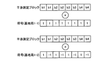
図3は、本実施の形態の干渉測定信号の構成例を示す図である。図3に示した例では、1フレーム内の干渉測定信号は、8つのブロックで構成される。以下、干渉測定信号を構成するブロックを干渉測定ブロックとも呼ぶ。干渉測定ブロックは、干渉測定ビットで構成される。干渉測定ビットとしては、任意のデータを用いることができる。図3では、4種類の干渉測定ブロックb1,b2,b3,b4を、それぞれを2回ずつ送信する例を示している。すなわち、同一の干渉測定ブロックが2つ連続して送信される。1フレーム内の干渉測定信号を構成する干渉測定ブロックの数は8に限定されず、干渉測定ブロックの数は任意の数とすることができる。また、同一の干渉測定ブロックを送信する回数も2回に限定されず、任意の回数とすることができる。
本実施の形態では、1フレーム内の8つの干渉測定ブロックに、符号が乗算される。この符号は、基地局1間で互いに異なる符号である。すなわち、この符号は、送信装置ごとに決定される。なお、全ての基地局1でそれぞれ異なる符号を用いる必要はなく、隣接する基地局1など、互いに干渉が発生し得る基地局1間で互いに異なる符号が用いられればよい。これにより、移動局3は、各基地局1から受信した干渉測定信号を識別することができる。互いに干渉が発生し得る基地局1で用いられる符号は、互いに直交する符号であることが望ましい。
さらに各ブロックには、お互いに干渉となる基地局間で、互いに直交する符号を乗算する。図3に示した例では、基地局1-1が干渉測定信号に乗算する符号ekを“+1,+1,+1,+1,+1,+1,+1,+1”とし、基地局1-2が干渉測定信号に乗算する符号fkを“+1,-1,+1,-1,+1,-1,+1,-1”としている。符号ekと符号fkとは互いに直交する符号である。なお、k番目のブロックに対応する符号をek,fkとそれぞれ記載する。例えば、図3に示した例においてk=0からk=7までの8つのブロックを示しているとすると、図3に示した例では、e0=+1,f0=+1,e1=+1,f1=-1,…である。
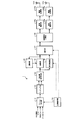
図4は、本実施の形態の基地局1の構成例を示す図である。下り通信における送信装置である基地局1は、図4に示すように、フレーム生成部101、マッピング部102、時空間符号化部103、差動部104、遅延部105、符号乗算部106、選択部107、送信信号分割部108、波形整形部109a,109b、無線送信部110a,110b、送信アンテナ111a,111bおよび送信制御部112を備える。なお、図4において、実線は送信されるデータの経路を示し、破線は送信制御部112から指示される指示信号の経路を示す。
図5は、本実施の形態の基地局1における送信処理手順の一例を示すフローチャートである。図4および図5を用いて、本実施の形態の基地局1の動作を説明する。なお、図5は1フレーム分の送信処理手順を示している。ここで、基地局1-1および基地局1-2の送信タイミングは同期しているものとする。基地局1間の送信タイミングを同期させる方法は、どのような方法を用いてもよいが、例えば、制御局4が送信タイミングを各基地局1へ指示する方法がある。または、GPS(Global Positioning System)を用いて時刻同期を行うことにより送信タイミングを同期させる方法、ある基地局1が基準となり、他の基地局1が無線通信または有線通信により、基地局1との間で任意の時刻同期方法で同期する方法などであってもよい。
図5に示すように、基地局1のフレーム生成部101は、干渉測定信号として送信されるデータである干渉測定ビットと、同期信号として送信されるデータである同期ビットと、データ信号として送信されるデータであるデータビットとを、送信制御部112からの指示に基づいてマッピング部102へ出力する(ステップS1)。送信制御部112は、フレームフォーマットにしたがった順序で、干渉測定ビット、同期ビットおよびデータビットがフレーム生成部101から出力されるよう、各ビットの出力タイミングをフレーム生成部101へ指示する。なお、干渉測定ビット、データビットおよび同期ビットは、送信制御部112からフレーム生成部101へ入力されてもよいし、図示しないデータ生成部により生成されてフレーム生成部101へ入力されてもよいし、制御局4から送信されてもよい。
マッピング部102は、フレーム生成部101から出力されるビットを、複素数で表されるシンボルにマッピングし、マッピングされたシンボルである送信シンボルを時空間符号化部103へ出力する(ステップS2)。すなわち、マッピング部102は、フレーム生成部101から出力されるビットを変調して送信シンボルを生成して時空間符号化部103へ出力する。マッピング部102が実施するマッピング方法は、どのような方法を用いてもよいが、例えば、QPSKにしたがったマッピング方法を用いることができる。
図6は、QPSKによるマッピングの一例を示す図である。図6において、横軸は複素数の実数部を示すI軸を示し、縦軸は、複素数の虚数部を示すQ軸を示している。図6に示すように、QPSKによるマッピングでは、2ビットを単位円の円周上の4つの信号点にマッピングする。具体的には、ビット“00”をπ/4[rad]の点に、ビット“01”を3π/4[rad]の点に、ビット“11”を5π/4[rad]の点に、ビット“10”を7π/4[rad]の点にマッピングする。なお、上述したIQ平面における信号点の角度は、I軸からの角度示す。
図5の説明に戻り、ステップS2の後、時空間符号化部103は、マッピング部102から出力されたシンボルである送信シンボルに対して時空間符号化処理を実施する(ステップS3)。具体的には、時空間符号化部103は、送信アンテナの数に等しい数のシンボルを1ブロックとし、ブロックごとの行列すなわち送信ブロックを生成し、差動部104および符号乗算部106へ出力する。すなわち、時空間符号化部103は、送信シンボルを時空間符号化することにより送信ブロックを生成する。以下では、図4に示したように、送信アンテナの数が2の場合、すなわち2シンボルを1ブロックとする場合について説明する。k(kは0以上の整数)番目のブロックを構成する2つのシンボルをそれぞれsk,1、sk,2とするとき、時空間符号化部103が生成する行列S(太字)kは以下の式(1)で表すことができる。

差動部104は、時空間符号化部103から出力される行列S(太字)kと、遅延部105から出力される行列C(太字)k-1とを用いて差動処理を実施する(ステップS5)。差動部104は、送信ブロックに対して差動処理を行う。具体的には、差動部104は、以下の式(2)に示すように、行列S(太字)kと、行列C(太字)k-1とを乗算することにより行列C(太字)kを生成し、選択部107および遅延部105へ出力する。行列C(太字)k-1は、1ブロック前すなわちk-1番目のブロックに対する差動部104の処理によって生成された行列である。遅延部105は、差動部104から入力された行列C(太字)kを保持し、次のブロックの処理を行う際に、差動部104へ出力する。
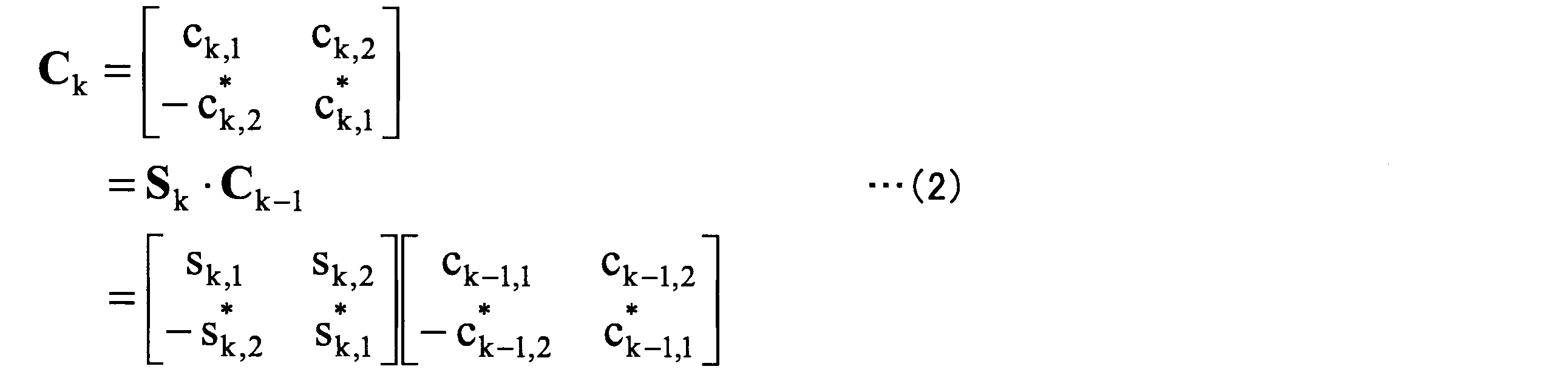
一方、符号乗算部106は、時空間符号化部103から出力される行列S(太字)kに符号を乗算する(ステップS4)。すなわち、符号乗算部106は、送信ブロックに符号を乗算する。符号乗算部106が行列S(太字)kに乗算する符号は、図3を用いた説明で述べたように、基地局1ごとに定められた符号である。符号乗算部106が行列S(太字)kに乗算する符号は、送信制御部112から指示される。なお、基地局1ごとに用いる符号は、あらかじめ各基地局1の送信制御部112に設定されていてもよいし、制御局4から指示されて送信制御部112が保持していてもよい。ここでは、図3で示した例のように、基地局1-1の符号乗算部106が符号ekを用いるとすると、基地局1-1の符号乗算部106は、以下の式(3)に示すように、行列S(太字)kに符号ekを乗算して行列C(太字)’kを生成し、行列C(太字)’kを選択部107へ出力する。

送信制御部112は、フレームフォーマットに基づいて、干渉測定信号の送信期間であるか否かを判断する(ステップS6)。干渉測定信号の送信期間である場合(ステップS6 Yes)、送信制御部112は、選択部107に対して、差動処理結果すなわち行列C(太字)kを選択するよう指示する(ステップS7)。選択部107は、送信制御部112からの指示にしたがって、差動部104から出力される行列C(太字)kを選択して送信信号分割部108へ出力する。
干渉測定信号の送信期間でない場合、すなわち同期信号またはデータ信号を送信する期間である場合(ステップS6 No)、送信制御部112は、選択部107に対して、符号乗算結果すなわち行列C(太字)’kを選択するよう指示する(ステップS8)。選択部107は、送信制御部112からの指示にしたがって、符号乗算部106から出力される行列C(太字)’kを選択して送信信号分割部108へ出力する。すなわち、選択部107は、差動処理後の送信ブロックと符号乗算後の送信ブロックとのうちいずれか一方を選択する。
ステップS7の後、およびステップS8の後、基地局1は、選択部107から出力された行列を無線信号として送信する(ステップS9)。具体的には、送信信号分割部108が、選択部107から入力される信号を送信アンテナ111a,111bにそれぞれ対応する2つの信号に分割する。詳細には、送信信号分割部108は、選択部107から出力された行列の1列目の2つのシンボルを送信アンテナ111aに対応する波形整形部109aに出力し、選択部107から出力された行列の2列目の2つのシンボルを送信アンテナ111bに対応する波形整形部109bに出力する。なお、送信アンテナの数が1の場合には、送信信号分割部108は設けられなくてもよい。
例えば、選択部107から出力された行列が行列C(太字)kである場合、送信信号分割部108は、ck,1および-c*
k,2を波形整形部109aに出力し、ck,2およびc*
k,1を波形整形部109bに出力する。波形整形部109a,109bは、入力された信号に対して、例えばルートナイキストフィルタによる波形整形を行い、波形整形後の信号をそれぞれ無線送信部110a,110bへ出力する。なお、波形整形部109a,109bにおける処理は、ルートナイキストフィルタによる波形整形に限定されず、一般的な任意の波形整形処理を用いることができる。なお、波形整形部109a,109bが、それぞれ無線送信部110a,110bの一部であってもよい。無線送信部110a,110bは、波形整形部109a,109bから出力された信号に対して、それぞれDA(Digital to Analog)変換、アップコンバート、増幅等の処理を行い、処理後の信号を送信アンテナ111a,111bからそれぞれ送信する。無線送信部110aおよび無線送信部110bは、選択部107によって選択された送信ブロックを送信する送信部である。なお、無線送信部110a,110bにおける処理は、上述した例に限定されず、一般的に無線通信における送信処理として行われる任意の処理でよい。
ステップS9の後、送信制御部112は、1フレームの送信が終了したか否かを判断し(ステップS10)、1フレームの送信が終了した場合(ステップS10 Yes)、処理を終了する。1フレームの送信が終了していない場合(ステップS10 No)、送信制御部112は、ステップS1からの処理を、再度、実施するよう制御する。このとき、ステップS1では、送信制御部112は、次のブロックのビットを出力するようフレーム生成部101へ指示する。以上の処理により、ブロックごとにステップS1からステップS9の処理が行われる。
なお、図5に示した例では、時空間符号化部103から出力された行列が差動部104および符号乗算部106へ入力されるが、送信制御部112が、フレームフォーマットに従って、時空間符号化部103へ行列の出力先を指定するようにしてもよい。すなわち、送信制御部112が、干渉測定ビットがフレーム生成部101から出力される場合には、出力先を符号乗算部106とし、同期ビットまたはデータビットがフレーム生成部101から出力される場合には、出力先を差動部104とするよう時空間符号化部103へ指示してもよい。
次に、本実施の形態の基地局1のハードウェア構成について説明する。本実施の形態の基地局1を構成する送信アンテナ111a,111bはアンテナであり、無線送信部110a,110bは送信機である。フレーム生成部101、マッピング部102、時空間符号化部103、差動部104、遅延部105、符号乗算部106、選択部107、送信信号分割部108、波形整形部109a,109bおよび送信制御部112の各部は処理回路により実現される。図7は、処理回路の構成例を示す図である。図7に示した処理回路500は、専用の回路として構成された処理回路である。処理回路500は、例えばASIC(Application Specific Integrated Circuit)、FPGA(Field Programmable Gate Array)、またはこれらを組み合わせたものを含む。
フレーム生成部101、マッピング部102、時空間符号化部103、差動部104、遅延部105、符号乗算部106、選択部107、送信信号分割部108、波形整形部109a,109bおよび送信制御部112を実現する処理回路はプロセッサを備える処理回路であってもよい。図8は、プロセッサを備える処理回路600の構成例を示す図である。図8に示した処理回路600は、プロセッサ601およびメモリ602を備える。プロセッサ601は、CPU(Central Processing Unit)、マイクロプロセッサ等が該当する。メモリ602は、RAM(Random Access Memory)、ROM(Read Only Memory)、フラッシュメモリー、等の、不揮発性または揮発性の半導体メモリ、磁気ディスク等が該当する。
フレーム生成部101、マッピング部102、時空間符号化部103、差動部104、遅延部105、符号乗算部106、選択部107、送信信号分割部108、波形整形部109a,109bおよび送信制御部112を実現する処理回路が、図8に示した処理回路600により実現される場合、各部の機能は、メモリ602に格納されたプログラムが、プロセッサ601により実行されることにより実現される。メモリ602は、プロセッサ601によりプログラムが実行される際の記憶領域としても用いられる。なお、フレーム生成部101、マッピング部102、時空間符号化部103、差動部104、遅延部105、符号乗算部106、選択部107、送信信号分割部108、波形整形部109a,109bおよび送信制御部112は、一部が専用の回路として構成された処理回路500により実現され、残部がプロセッサ601を備える処理回路600により実現されてもよい。
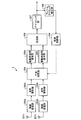
次に、本実施の形態の下り通信における受信装置である移動局3について説明する。図9は、本実施の形態の移動局3の構成例を示す図である。図9に示すように、移動局3は、受信アンテナ201a,201b、無線受信部202a,202b、波形整形部203a,203b、干渉抑圧部204、差動時空間復号部205a,205b、合成部206、デマッピング部207、フレームタイミング検出部208および受信制御部209を備える。
移動局3の動作について、図9を用いて説明する。移動局3は、複数の基地局1から送信された信号を受信可能な受信装置である。受信アンテナ201a,201bは、複数の基地局1から送信された信号を含む受信信号を受信する複数の受信アンテナの一例である。受信アンテナの数は2に限定されない。なお、以下の説明では、移動局3の通信相手が基地局1-1であり、基地局1-1から送信された無線信号が所望信号であり、基地局1-2から送信された無線信号が干渉信号であるとして説明する。
無線受信部202a,202bは、それぞれ受信アンテナ201a,201bによって受信された信号に対して、それぞれ増幅、ダウンコンバート、AD(Analog to Digital)変換等の処理を行い、処理後の信号をそれぞれ波形整形部203a,203bへ出力する。なお、無線受信部202a,202bにおける処理は、これらに限定されず、一般的な受信処理でよい。
波形整形部203a,203bは、それぞれ無線受信部202a,202bから出力された信号に対して、例えばルートナイキストフィルタにより、所望信号の帯域外の信号成分を除去するとともに所望信号に対する波形整形を行う。波形整形部203a,203bが行う波形整形処理は、ルートナイキストフィルタを用いた処理に限定されない。
干渉抑圧部204は、干渉抑圧処理を実施する。以下では、干渉抑圧処理として、ZF(Zero Forcing)方式による処理を行う例を説明するが、MMSE(Minimum Mean Square Error)方式など、他の方式を用いた干渉抑圧処理を実施してもよい。
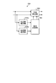
図10は、干渉抑圧部204の構成例を示す図である。図10に示すように、干渉抑圧部204は、伝送路推定部301a,301b、重み計算部302および干渉除去部303を備える。
図10を用いて、干渉抑圧部204の動作について説明する。なお、干渉抑圧部204の動作タイミングは受信制御部209によって制御される。受信制御部209は、フレームフォーマットにしたがって、伝送路推定部301a,301bおよび重み計算部302の処理が干渉測定信号を受信する期間で行われ、干渉除去部303の処理が同期信号およびデータ信号を受信する期間で行われるように、各部を制御する。
伝送路推定部301a,301bは、それぞれ受信アンテナ201a,201aにより受信された信号に含まれる干渉信号の伝送路推定を行う。具体的には、伝送路推定部301a,301bは、以下のように、受信信号から干渉源となる送信装置すなわち基地局1-2から送信された信号である干渉信号を分離し、受信アンテナ201a,201aごとに干渉信号の伝送路を推定する。詳細には、伝送路推定部301a,301bは、受信信号に含まれる干渉測定用の干渉測定ビットである干渉測定信号を用いて干渉信号の伝送路を推定する。受信アンテナy(y=0,1)で受信されるk番目のブロックの受信信号をrk,1[y]、rk,2[y]とするとき、受信信号行列R(太字)k[y]は式(4)で表すことができる。なお、y=0が、受信アンテナ201aに対応し、y=1が、受信アンテナ201bに対応する。また、行列C(太字)kは基地局1-1から送信された信号を表す行列であり、行列D(太字)kは基地局1-2から送信された信号を表す行列であり、行列H(太字)k[y]は基地局1-1と移動局3の受信アンテナyとの間の伝送路を表す行列であり、行列G(太字)k[y]は基地局1-2と移動局3の受信アンテナyとの間の伝送路を表す行列である。

基地局1-1の送信アンテナx(x=0,1)と移動局3の受信アンテナy(y=0,1)との間の伝送路を、hk[x,y]とし、基地局1-2の伝送路をgk[x,y]とするとき、行列C(太字)k、行列D(太字)k、行列H(太字)k[y]、行列G(太字)k[y]の各行列は、それぞれ式(5)、式(6)、式(7)、式(8)で表すことができる。なお、x=0が送信アンテナ111aに対応し、x=1が送信アンテナ111bに対応する。



次に、伝送路の推定対象である基地局1-2で用いられる符号fkを式(4)に乗算し、直交が取れる2ブロックの信号を加算した結果は、図3に示したように2ブロックで同じ信号を送信することすなわちC(太字)k=C(太字)k+1、D(太字)k=D(太字)k+1であること、および、伝送路の変動がないことすなわちH(太字)k[y]=H(太字)k+1[y]、G(太字)k[y]=G(太字)k+1[y]であること、を仮定することにより、式(9)のように表される。

上記式(9)に、送信信号を示す行列D(太字)kの逆行列を乗算することで、基地局1-2の伝送路を示す行列G(太字)k[y]は以下の式(10)のように求めることができる。伝送路推定部301a,301bは、式(10)に基づいて、対応する受信アンテナで受信された干渉信号の伝送路をそれぞれ推定する。なお、基地局1-2の符号fkは基地局1-1から送信される制御信号に含まれることにより、または基地局1-1から送信されるデータ信号に含まれることにより、基地局1-1から移動局3に通知される。

重み計算部302は、伝送路推定部301a,302aの出力する伝送路推定値gk[x,0]、gk [x,1]を用い、式(11)から式(13)によって、3つの重みw00,w11,w01を計算する。なお、受信制御部209より、干渉抑圧処理を停止するよう指示される場合は、w00=1、w11=1、w01=0とする。



ここで、I00、I11、I01、cは、式(14)、式(15)、式(16)、式(17)、式(18)で表される。





干渉除去部303は、以下の式(19)、式(20)によって、各受信アンテナの受信信号rk[y]から干渉信号を除去し、干渉信号を除去した信号qk[y]を差動時空間復号部205a,205bへ出力する。すなわち、干渉除去部303は、干渉信号の伝送路の推定結果を用いて、複数の受信アンテナのうちの1つである第1の受信アンテナによって受信された受信信号における干渉信号を、第1の受信アンテナ以外の受信アンテナである第2の受信アンテナにより受信された受信信号を用いて除去する。以下の式(19)では、第1の受信アンテナはy=0に対応する受信アンテナ201aであり、第2の受信アンテナはy=1に対応する受信アンテナ201bであり、式(20)では、第1の受信アンテナがy=1に対応する受信アンテナ201bであり、第2の受信アンテナはy=0に対応する受信アンテナ201aである。


差動時空間復号部205a,205bは、それぞれ受信アンテナ201a,201bにより受信された信号に対して干渉除去された受信信号であるqk,1[y]、qk,2[y]を用いて、ブロック単位に行列を生成し、式(21)に示す差動時空間復号により、受信アンテナyの送信シンボル推定値を出力する。

ここで、Q(太字)k[y]は、以下の式(22)、式(23)で表される。


合成部206は、式(24)、式(25)に示すように、各受信アンテナの送信シンボル推定値s(ハット)k,1[y]、s(ハット)k,2[y]を加算し、送信シンボル推定値s(ハット)k,1、s(ハット)k,2を得る。合成部206は、送信シンボル推定値s(ハット)k,1、s(ハット)k,2をデマッピング部207へ出力する。


デマッピング部207は、合成部206から出力されたシンボル推定値をビット系列に変換する。例えば、基地局1におけるマッピングでQPSKが用いられた場合、デマッピング部207ではQPSKに対応したデマッピングが行われる。基地局1におけるマッピングでQPSKが用いられた場合、デマッピングでは1つのシンボル推定値から2ビットに変換されるが、複素数のシンボル推定値の虚部と実部の各符号によって、デマッピング部207は、ビット値を判定すればよい。具体的には、虚部と実部の各符号によって2ビットのそれぞれのビットを、正の場合は0、負の場合は1とする。
フレームタイミング検出部208は、デマッピングで変換されたビット系列の中から同期信号すなわち同期ビット系列を抽出する。フレーム中の同期ビット系列の位置は既知のため、同期ビット系列が抽出されたタイミングから、フレームタイミングすなわちフレームの先頭のタイミングを得ることができる。
受信制御部209は、フレームタイミング検出部208で検出されたフレームタイミングに基づいて、干渉抑圧部204の動作を制御する。具体的には、受信制御部209は、干渉抑圧部204の伝送路推定部301a,301bと重み計算部302とは、干渉測定信号を受信しているときに動作するよう干渉抑圧部204を制御する。また、受信制御部209は、干渉除去部303が同期信号とデータ信号を受信しているときに動作するよう干渉抑圧部204を制御する。なお、移動局3が、基地局1からの受信を開始した時など、受信制御部209は、フレームタイミングが不明の場合は、干渉抑圧処理を停止するよう制御する。
以上のように、本実施の形態では、基地局1が、同期信号とデータ信号に対しては差動時空間符号化を施し、干渉測定信号に対しては時空間符号化を施して、同期信号、データ信号および干渉測定信号を送信するようにした。すなわち、基地局1が送信する送信ブロックは、干渉測定用の干渉測定ビットで構成される干渉測定ブロックを含み、符号乗算部106は、干渉測定ブロックに符号を乗算する。また、送信ブロックは、送信される情報を示すデータで構成されるデータブロックを含み、差動部104は、データブロックに差動処理を行う。このため、基地局1から送信された信号を受信した移動局3は、データ信号の復号においては伝送路推定を行う必要がなく、かつ受信した干渉測定信号を用いて伝送路推定を行うことができるため干渉抑制処理を行うことができる。また、送信装置、受信装置ともに簡易な構成で、差動時空間符号化に対する干渉抑圧を実現することができる。
以上の実施の形態に示した構成は、本発明の内容の一例を示すものであり、別の公知の技術と組み合わせることも可能であるし、本発明の要旨を逸脱しない範囲で、構成の一部を省略、変更することも可能である。
1,1-1,1-2 基地局、2-1,2-2 通信エリア、3 移動局、4 制御局、10 無線通信システム、101 フレーム生成部、102 マッピング部、103 時空間符号化部、104 差動部、105 遅延部、106 符号乗算部、107 選択部、108 送信信号分割部、109a,109b 波形整形部、110a,110b 無線送信部、111a,111b 送信アンテナ、112 送信制御部、201a,201b 受信アンテナ、202a,202b 無線受信部、203a,203b 波形整形部、204 干渉抑圧部、205a,205b 差動時空間復号部、206 合成部、207 デマッピング部、208 フレームタイミング検出部、209 受信制御部、301a,301b 伝送路推定部、302 重み計算部、303 干渉除去部。
Claims (8)
- 送信シンボルを時空間符号化することにより送信ブロックを生成する時空間符号化部と、
前記送信ブロックに対して差動処理を行う差動部と、
前記送信ブロックに符号を乗算する符号乗算部と、
前記差動処理後の前記送信ブロックと前記符号乗算後の前記送信ブロックとのうちいずれか一方を選択する選択部と、
前記選択された前記送信ブロックを送信する送信部と、
を備えることを特徴とする送信装置。 - 前記送信ブロックは、干渉測定用の干渉測定ビットで構成される干渉測定ブロックを含み、
前記符号乗算部は、前記干渉測定ブロックに前記符号を乗算することを特徴とする請求項1に記載の送信装置。 - 前記送信ブロックは、送信される情報を示すデータで構成されるデータブロックを含み、
前記差動部は、前記データブロックに前記差動処理を行うことを特徴とする請求項2に記載の送信装置。 - 同一の前記干渉測定ブロックが2つ連続して送信されることを特徴とする請求項2または3に記載の送信装置。
- 前記符号は、前記送信装置ごとに決定されることを特徴とする請求項1から4のいずれか1つに記載の送信装置。
- 複数の請求項1から5のいずれか1つに記載の送信装置から送信された信号を受信可能な受信装置であって、
複数の前記送信装置から送信された信号を含む受信信号を受信する複数の受信アンテナと、
前記受信信号から干渉源となる前記送信装置から送信された信号である干渉信号を分離し、前記受信アンテナごとに前記干渉信号の伝送路を推定する伝送路推定部と、
前記伝送路の推定結果を用いて、複数の前記受信アンテナのうちの1つである第1の受信アンテナによって受信された前記受信信号における干渉信号を、前記第1の受信アンテナ以外の前記受信アンテナである第2の受信アンテナにより受信された前記受信信号を用いて除去する干渉除去部と、
を備えることを特徴とする受信装置。 - 前記伝送路推定部は、前記受信信号に含まれる干渉測定用の干渉測定ビットを用いて干渉信号の伝送路を推定することを特徴とする請求項6に記載の受信装置。
- 複数の請求項1から5のいずれか1つに記載の送信装置と、
前記送信装置から送信された信号を受信可能な請求項6または7に記載の受信装置と、
を備えることを特徴とする無線通信システム。
Priority Applications (5)
| Application Number | Priority Date | Filing Date | Title |
|---|---|---|---|
| PCT/JP2017/022153 WO2018229943A1 (ja) | 2017-06-15 | 2017-06-15 | 送信装置、受信装置および無線通信システム |
| EP17913139.6A EP3624375A4 (en) | 2017-06-15 | 2017-06-15 | TRANSMITTER, RECEIVER AND WIRELESS COMMUNICATION SYSTEM |
| JP2019524667A JP6587781B2 (ja) | 2017-06-15 | 2017-06-15 | 送信装置、受信装置および無線通信システム |
| CN201780091746.XA CN110741582A (zh) | 2017-06-15 | 2017-06-15 | 发送装置、接收装置以及无线通信系统 |
| US16/606,432 US11218252B2 (en) | 2017-06-15 | 2017-06-15 | Transmission device, receiving device, and wireless communication system |
Applications Claiming Priority (1)
| Application Number | Priority Date | Filing Date | Title |
|---|---|---|---|
| PCT/JP2017/022153 WO2018229943A1 (ja) | 2017-06-15 | 2017-06-15 | 送信装置、受信装置および無線通信システム |
Publications (1)
| Publication Number | Publication Date |
|---|---|
| WO2018229943A1 true WO2018229943A1 (ja) | 2018-12-20 |
Family
ID=64659818
Family Applications (1)
| Application Number | Title | Priority Date | Filing Date |
|---|---|---|---|
| PCT/JP2017/022153 Ceased WO2018229943A1 (ja) | 2017-06-15 | 2017-06-15 | 送信装置、受信装置および無線通信システム |
Country Status (5)
| Country | Link |
|---|---|
| US (1) | US11218252B2 (ja) |
| EP (1) | EP3624375A4 (ja) |
| JP (1) | JP6587781B2 (ja) |
| CN (1) | CN110741582A (ja) |
| WO (1) | WO2018229943A1 (ja) |
Cited By (2)
| Publication number | Priority date | Publication date | Assignee | Title |
|---|---|---|---|---|
| US11218252B2 (en) * | 2017-06-15 | 2022-01-04 | Mitsubishi Electric Corporation | Transmission device, receiving device, and wireless communication system |
| JP7053965B1 (ja) * | 2021-03-24 | 2022-04-12 | 三菱電機株式会社 | 送信装置、受信装置、通信装置、無線通信システム、制御回路、記憶媒体、送信方法および受信方法 |
Families Citing this family (1)
| Publication number | Priority date | Publication date | Assignee | Title |
|---|---|---|---|---|
| CN116418454A (zh) * | 2021-12-30 | 2023-07-11 | 维沃移动通信有限公司 | 编码方法、设备及可读存储介质 |
Citations (3)
| Publication number | Priority date | Publication date | Assignee | Title |
|---|---|---|---|---|
| JP2014045284A (ja) * | 2012-08-24 | 2014-03-13 | Mitsubishi Electric Corp | 通信システム、送信装置および受信装置 |
| JP2015154449A (ja) * | 2014-02-19 | 2015-08-24 | 三菱電機株式会社 | 受信装置、通信装置および受信方法 |
| JP2016154305A (ja) * | 2015-02-20 | 2016-08-25 | 三菱電機株式会社 | 受信装置 |
Family Cites Families (68)
| Publication number | Priority date | Publication date | Assignee | Title |
|---|---|---|---|---|
| JP2586840B2 (ja) * | 1994-12-05 | 1997-03-05 | 日本電気株式会社 | 移動通信システム |
| GB2357937B (en) * | 1999-12-23 | 2003-04-02 | Mitel Corp | DMT bit allocation with imperfect teq |
| US6411817B1 (en) * | 2000-01-21 | 2002-06-25 | Lucent Technologies Inc. | Method and system for dynamic downlink power control in a time-division, multiplex wireless system |
| CN1484899A (zh) * | 2000-12-20 | 2004-03-24 | ���˹���Ѷ��� | 差分空时块编码 |
| EP1400062A2 (en) * | 2001-06-28 | 2004-03-24 | King's College London | Electronic data communication system |
| US7773699B2 (en) * | 2001-10-17 | 2010-08-10 | Nortel Networks Limited | Method and apparatus for channel quality measurements |
| DE60332893D1 (de) | 2002-04-25 | 2010-07-22 | Imec | CDMA Empfang-übertragungstechniken für Funksysteme mit Mehrfacheingängen und Mehrfachausgängen (MIMO) |
| CN100472998C (zh) * | 2003-02-13 | 2009-03-25 | 株式会社Ntt都科摩 | 差分多长度发送及接收分集 |
| KR100957344B1 (ko) * | 2003-04-25 | 2010-05-12 | 삼성전자주식회사 | 채널의 전력을 이용한 차등 공간-시간 블럭 부호의 송수신방법 및 장치 |
| US8064528B2 (en) * | 2003-05-21 | 2011-11-22 | Regents Of The University Of Minnesota | Estimating frequency-offsets and multi-antenna channels in MIMO OFDM systems |
| US7769097B2 (en) * | 2003-09-15 | 2010-08-03 | Intel Corporation | Methods and apparatus to control transmission of a multicarrier wireless communication channel through multiple antennas |
| KR100981580B1 (ko) * | 2003-12-23 | 2010-09-10 | 삼성전자주식회사 | 8 개 이하의 송신 안테나를 사용하는 차등 시공간 블록 부호 송수신 장치 |
| WO2005096531A1 (en) * | 2004-04-02 | 2005-10-13 | Nortel Networks Limited | Wireless comunication methods, systems, and signal structures |
| JP4099592B2 (ja) * | 2004-06-10 | 2008-06-11 | ソニー株式会社 | 通信システム、送信装置および受信装置 |
| KR100780363B1 (ko) | 2004-08-27 | 2007-11-29 | 삼성전자주식회사 | 2개의 송신안테나를 위한 최대 다이버시티 최대 전송율을갖는 시공간 블록 부호화 장치 및 방법 |
| KR100913873B1 (ko) * | 2004-09-13 | 2009-08-26 | 삼성전자주식회사 | 고속 전송률을 가지는 차등 시공간 블록 부호 장치 및 방법 |
| CN102244637B (zh) | 2004-12-28 | 2014-07-30 | 松下电器产业株式会社 | 发送装置以及发送方法 |
| EP1750385A1 (en) * | 2005-08-03 | 2007-02-07 | THOMSON Licensing | Method and device for multimedia multicast transmission over a wireless network |
| CA2648999A1 (en) * | 2006-04-10 | 2007-10-18 | Noam Amram | A method device and system for receiving a communication signal |
| EP1883193A3 (en) * | 2006-05-22 | 2011-06-29 | Edgewater Computer Systems, Inc. | Data communication system |
| US7907690B2 (en) * | 2006-10-17 | 2011-03-15 | Edgewater Computer Systems, Inc. | Interference cancellation system and method using impulse response |
| CN101467363B (zh) * | 2006-06-14 | 2012-11-07 | 国立大学法人九州大学 | 传输系统、传输方法、发送装置、接收装置、解码方法及解码装置 |
| KR100809604B1 (ko) * | 2006-12-06 | 2008-03-04 | 한국전자통신연구원 | 상호 협력 전송에서 신호점 회전을 이용한 신호 송/수신장치 및 방법 |
| US7974571B2 (en) * | 2007-01-09 | 2011-07-05 | Viasat, Inc. | Multi-antenna satellite system with wireless interface to vehicle |
| FR2928509B1 (fr) * | 2008-03-04 | 2011-01-14 | Commissariat Energie Atomique | Procede de codage spatio-temporel differentiel. |
| KR101435601B1 (ko) * | 2008-04-02 | 2014-09-01 | 삼성전자주식회사 | 광대역 무선 통신 시스템의 자동 간섭 제어 장치 및 방법 |
| JP2009303086A (ja) * | 2008-06-17 | 2009-12-24 | Hitachi Kokusai Electric Inc | シンボルタイミング同期方法、無線通信システム及び移動局装置 |
| US8089916B2 (en) * | 2009-04-07 | 2012-01-03 | Indian Institute Of Science | Leveraging coherent distributed space-time codes for noncoherent communication in relay networks via training |
| KR101427500B1 (ko) * | 2010-02-26 | 2014-08-07 | 가부시키가이샤 히다치 고쿠사이 덴키 | 송신기 |
| WO2011125329A1 (ja) * | 2010-04-07 | 2011-10-13 | 株式会社日立国際電気 | 送信機及び送信方法 |
| JP5452375B2 (ja) * | 2010-06-03 | 2014-03-26 | 株式会社日立製作所 | 基地局 |
| ES2651485T3 (es) * | 2010-06-17 | 2018-01-26 | Sun Patent Trust | Método y transmisor de precodificación |
| JP5843126B2 (ja) * | 2010-06-30 | 2016-01-13 | 株式会社日立国際電気 | 列車無線通信システム、基地局装置及び無線通信方法 |
| JP5623248B2 (ja) * | 2010-09-10 | 2014-11-12 | パナソニックインテレクチュアル プロパティ コーポレーション オブアメリカPanasonic Intellectual Property Corporation of America | 送信方法、送信装置、受信方法および受信装置 |
| PH12013500211A1 (en) * | 2010-12-10 | 2013-03-11 | Sun Patent Trust | Precoding method, and transmitting device |
| JP5671328B2 (ja) * | 2010-12-21 | 2015-02-18 | 株式会社日立国際電気 | 受信装置、通信システム及び通信方法 |
| CN102594737B (zh) * | 2011-01-05 | 2015-04-01 | 中兴通讯股份有限公司 | 一种邻区干扰检测方法及系统 |
| CN107104716B (zh) * | 2011-04-19 | 2020-10-02 | 太阳专利托管公司 | 信号生成方法及装置、信号处理方法及装置 |
| JP5763963B2 (ja) | 2011-04-25 | 2015-08-12 | 株式会社日立国際電気 | 受信機、受信方法及び無線通信システム |
| US20120300877A1 (en) * | 2011-05-27 | 2012-11-29 | Yutaka Murakami | Precoding method, transmitting device, and receiving device |
| US8907921B2 (en) * | 2011-08-30 | 2014-12-09 | Synaptics Incorporated | Interference sensing within a display device with an integrated sensing device |
| CN103248459B (zh) * | 2012-02-14 | 2016-09-14 | 延世大学校产学协力团 | 用于在差分正交空时分组编码系统中解码的方法和装置 |
| WO2013128983A1 (ja) * | 2012-02-27 | 2013-09-06 | 三菱電機株式会社 | 通信システム、送信装置および受信装置 |
| CN104145462B (zh) * | 2012-03-02 | 2017-03-01 | 三菱电机株式会社 | 无线发送装置、无线接收装置以及数据传送方法 |
| JP6027368B2 (ja) * | 2012-08-10 | 2016-11-16 | 株式会社Nttドコモ | ユーザ端末、無線通信方法及び無線通信システム |
| US10020859B2 (en) * | 2013-01-17 | 2018-07-10 | Nec Corporation | Channel feedback for vertical and full-dimensional beamforming |
| JP6176801B2 (ja) * | 2013-09-26 | 2017-08-09 | 株式会社日立国際電気 | 無線通信システム及び送信機 |
| JPWO2015118582A1 (ja) * | 2014-02-05 | 2017-03-23 | 三菱電機株式会社 | 基地局、通信システム、通信方法 |
| EP3110034B1 (en) * | 2014-02-18 | 2019-06-26 | LG Electronics Inc. | Method for transreceiving signals using user-specific flexible tdd technology in wireless communication system and device for same |
| US9088447B1 (en) * | 2014-03-21 | 2015-07-21 | Mitsubishi Electric Research Laboratories, Inc. | Non-coherent transmission and equalization in doubly-selective MIMO channels |
| CN107078854B (zh) * | 2014-11-11 | 2020-07-07 | 瑞典爱立信有限公司 | 发送节点、接收节点和在其中执行的方法 |
| CN107210801B (zh) * | 2015-02-05 | 2021-07-02 | Lg 电子株式会社 | 无线通信系统中执行干扰测量的方法及其装置 |
| US9264118B1 (en) * | 2015-03-02 | 2016-02-16 | Mitsubishi Electric Research Laboratories, Inc. | System and method for communicating data symbols via wireless doubly-selective channels |
| WO2016186378A1 (ko) * | 2015-05-15 | 2016-11-24 | 엘지전자 주식회사 | 다중 안테나 무선 통신 시스템에서의 참조신호 정보 피드백 방법 및 이를 위한 장치 |
| JP6246426B2 (ja) * | 2015-06-04 | 2017-12-13 | 三菱電機株式会社 | 送信装置および受信装置 |
| EP3107235B1 (en) * | 2015-06-16 | 2019-08-14 | Mitsubishi Electric R&D Centre Europe B.V. | A method for computing likelihoods in a process for reconstructing decoded information words |
| US20160376640A1 (en) * | 2015-06-25 | 2016-12-29 | Beckman Coulter, Inc. | Determination of exosome purity methods and apparatus |
| CN105120503B (zh) * | 2015-07-17 | 2019-03-22 | 杭州电子科技大学 | 无线传感器网络中一种高能效节点协作传输方法 |
| WO2017034270A1 (ko) * | 2015-08-21 | 2017-03-02 | 엘지전자(주) | 무선 통신 시스템에서 채널 상태 정보 송수신 방법 및 이를 위한 장치 |
| WO2017061822A1 (ko) * | 2015-10-07 | 2017-04-13 | 엘지전자(주) | 무선 통신 시스템에서 채널 상태 정보 송수신 방법 및 이를 위한 장치 |
| EP3536085A4 (en) * | 2016-11-04 | 2020-06-24 | Telefonaktiebolaget LM Ericsson (publ) | SYSTEMS AND METHODS FOR HANDLING NON-TYPICAL INTERFERENCE IN WIRELESS COMMUNICATION NETWORKS |
| DK3806376T3 (da) * | 2017-05-05 | 2022-08-01 | Ericsson Telefon Ab L M | Interferensmålinger og kanaltilstandsinformation-feedback til Multi-User Multiple-In Multiple-Out |
| US20200127765A1 (en) * | 2017-05-10 | 2020-04-23 | Mitsubishi Electric Corporation | Transmitter, base station device, and wireless communication system |
| WO2018229943A1 (ja) * | 2017-06-15 | 2018-12-20 | 三菱電機株式会社 | 送信装置、受信装置および無線通信システム |
| WO2019163037A1 (ja) * | 2018-02-21 | 2019-08-29 | 三菱電機株式会社 | 無線通信システムおよび無線通信方法 |
| US11616595B2 (en) * | 2018-10-09 | 2023-03-28 | Qualcomm Incorporated | Multi-channel listen before talk with wideband transmission in new radio in unlicensed spectrum |
| JP6903241B2 (ja) * | 2019-01-11 | 2021-07-14 | 三菱電機株式会社 | 受信装置、無線通信システム、無線通信方法、制御回路およびプログラム |
| US11445514B2 (en) * | 2019-08-23 | 2022-09-13 | Qualcomm Incorporated | Beam determination prior to beam activation indication |
-
2017
- 2017-06-15 WO PCT/JP2017/022153 patent/WO2018229943A1/ja not_active Ceased
- 2017-06-15 US US16/606,432 patent/US11218252B2/en active Active
- 2017-06-15 EP EP17913139.6A patent/EP3624375A4/en not_active Withdrawn
- 2017-06-15 JP JP2019524667A patent/JP6587781B2/ja active Active
- 2017-06-15 CN CN201780091746.XA patent/CN110741582A/zh active Pending
Patent Citations (3)
| Publication number | Priority date | Publication date | Assignee | Title |
|---|---|---|---|---|
| JP2014045284A (ja) * | 2012-08-24 | 2014-03-13 | Mitsubishi Electric Corp | 通信システム、送信装置および受信装置 |
| JP2015154449A (ja) * | 2014-02-19 | 2015-08-24 | 三菱電機株式会社 | 受信装置、通信装置および受信方法 |
| JP2016154305A (ja) * | 2015-02-20 | 2016-08-25 | 三菱電機株式会社 | 受信装置 |
Non-Patent Citations (3)
| Title |
|---|
| HIROYASU SANO, SINJI MASUDA, FUMIO ISHIZU: "A study on the code multiplexing scheme for differential space-time blocking", PROCEEDINGS OF THE 2012 IEICE COMMUNICATIONS SOCIETY CONFERENCE 1, 28 August 2012 (2012-08-28), pages 387, XP009516861 * |
| See also references of EP3624375A4 |
| V. TAROKHH. JAFARKHANI: "A Differential Detection Scheme for Transmit Diversity", IEEE JOURNAL ON SELECTED AREAS IN COMMUNICATIONS, vol. 18, no. 7, July 2000 (2000-07-01) |
Cited By (3)
| Publication number | Priority date | Publication date | Assignee | Title |
|---|---|---|---|---|
| US11218252B2 (en) * | 2017-06-15 | 2022-01-04 | Mitsubishi Electric Corporation | Transmission device, receiving device, and wireless communication system |
| JP7053965B1 (ja) * | 2021-03-24 | 2022-04-12 | 三菱電機株式会社 | 送信装置、受信装置、通信装置、無線通信システム、制御回路、記憶媒体、送信方法および受信方法 |
| US20230396408A1 (en) * | 2021-03-24 | 2023-12-07 | Mitsubishi Electric Corporation | Transmitting apparatus, receiving apparatus, communication apparatus, wireless communication system, control circuit, storage medium, transmission method, and reception method |
Also Published As
| Publication number | Publication date |
|---|---|
| JPWO2018229943A1 (ja) | 2019-11-21 |
| EP3624375A1 (en) | 2020-03-18 |
| US11218252B2 (en) | 2022-01-04 |
| JP6587781B2 (ja) | 2019-10-09 |
| CN110741582A (zh) | 2020-01-31 |
| EP3624375A4 (en) | 2020-06-03 |
| US20210111834A1 (en) | 2021-04-15 |
Similar Documents
| Publication | Publication Date | Title |
|---|---|---|
| JP5793184B2 (ja) | 送信装置、受信装置、送信方法、受信方法 | |
| JP2009171025A (ja) | 移動局装置及び基地局装置、並びに無線通信システム | |
| JP2009303086A (ja) | シンボルタイミング同期方法、無線通信システム及び移動局装置 | |
| JP5671328B2 (ja) | 受信装置、通信システム及び通信方法 | |
| JP6587781B2 (ja) | 送信装置、受信装置および無線通信システム | |
| JP6618655B2 (ja) | 送信装置、無線通信システム、処理回路およびプログラム | |
| JP6685485B1 (ja) | 送信装置、受信装置、通信装置、無線通信システム、制御回路および記憶媒体 | |
| US8553803B2 (en) | Estimation of the signal to interference and noise ratio (SINR) in multiple input multiple output (MIMO) systems | |
| CN113424504B (zh) | 无线电信基站及用于高移动性情景的过程 | |
| US20240357428A1 (en) | Information processing apparatus, information processing method, computer readable medium, and wireless communication system | |
| JP6903241B2 (ja) | 受信装置、無線通信システム、無線通信方法、制御回路およびプログラム | |
| WO2013129146A1 (ja) | チャネル推定方法および受信機 | |
| EP4203404A1 (en) | Device and method for transmitting control data with moderate low peak-to-average power ratio | |
| JP6877659B2 (ja) | 無線送信装置、無線受信装置、遠隔通信監視システム、無線通信システム、無線通信方法、制御回路およびプログラム | |
| KR20150101165A (ko) | 이동통신 시스템에서 수신기의 타이밍 옵셋 추정 방법 및 그 장치 | |
| KR20160043897A (ko) | Mimo 시스템에서 공통 신호를 생성하는 방법 및 장치 | |
| US12526175B2 (en) | Pulse shaping-based reference signals | |
| US20260020076A1 (en) | Location-based random access | |
| US20250141719A1 (en) | Methods and apparatus for pulse shaped and overlapped phase tracking reference signals | |
| US20240406050A1 (en) | System and method for carrier frequency offset estimation | |
| KR101787946B1 (ko) | 다중 안테나를 사용하는 무선 이동 통신 기반의 협력 통신 시스템 및 그 방법 | |
| KR20240056327A (ko) | 이종 프로토콜 통신을 위한 전자 장치, 이를 포함하는 통신 시스템 및 그 동작 방법 | |
| WO2021199812A1 (ja) | 通信装置および通信方法 | |
| JP2014120836A (ja) | 送信装置および符号化方法 | |
| WO2016143411A1 (ja) | 送信装置 |
Legal Events
| Date | Code | Title | Description |
|---|---|---|---|
| 121 | Ep: the epo has been informed by wipo that ep was designated in this application |
Ref document number: 17913139 Country of ref document: EP Kind code of ref document: A1 |
|
| ENP | Entry into the national phase |
Ref document number: 2019524667 Country of ref document: JP Kind code of ref document: A |
|
| ENP | Entry into the national phase |
Ref document number: 2017913139 Country of ref document: EP Effective date: 20191211 |
|
| NENP | Non-entry into the national phase |
Ref country code: DE |