WO2018230033A1 - レンズ系、カメラシステム及び撮像システム - Google Patents
レンズ系、カメラシステム及び撮像システム Download PDFInfo
- Publication number
- WO2018230033A1 WO2018230033A1 PCT/JP2018/004774 JP2018004774W WO2018230033A1 WO 2018230033 A1 WO2018230033 A1 WO 2018230033A1 JP 2018004774 W JP2018004774 W JP 2018004774W WO 2018230033 A1 WO2018230033 A1 WO 2018230033A1
- Authority
- WO
- WIPO (PCT)
- Prior art keywords
- lens
- image
- lens system
- image sensor
- free
- Prior art date
- Legal status (The legal status is an assumption and is not a legal conclusion. Google has not performed a legal analysis and makes no representation as to the accuracy of the status listed.)
- Ceased
Links
Images





Classifications
-
- G—PHYSICS
- G02—OPTICS
- G02B—OPTICAL ELEMENTS, SYSTEMS OR APPARATUS
- G02B9/00—Optical objectives characterised both by the number of the components and their arrangements according to their sign, i.e. + or -
- G02B9/64—Optical objectives characterised both by the number of the components and their arrangements according to their sign, i.e. + or - having more than six components
-
- G—PHYSICS
- G02—OPTICS
- G02B—OPTICAL ELEMENTS, SYSTEMS OR APPARATUS
- G02B13/00—Optical objectives specially designed for the purposes specified below
- G02B13/001—Miniaturised objectives for electronic devices, e.g. portable telephones, webcams, PDAs, small digital cameras
- G02B13/0015—Miniaturised objectives for electronic devices, e.g. portable telephones, webcams, PDAs, small digital cameras characterised by the lens design
- G02B13/002—Miniaturised objectives for electronic devices, e.g. portable telephones, webcams, PDAs, small digital cameras characterised by the lens design having at least one aspherical surface
- G02B13/0045—Miniaturised objectives for electronic devices, e.g. portable telephones, webcams, PDAs, small digital cameras characterised by the lens design having at least one aspherical surface having five or more lenses
-
- G—PHYSICS
- G02—OPTICS
- G02B—OPTICAL ELEMENTS, SYSTEMS OR APPARATUS
- G02B13/00—Optical objectives specially designed for the purposes specified below
- G02B13/04—Reversed telephoto objectives
-
- G—PHYSICS
- G02—OPTICS
- G02B—OPTICAL ELEMENTS, SYSTEMS OR APPARATUS
- G02B13/00—Optical objectives specially designed for the purposes specified below
- G02B13/08—Anamorphotic objectives
-
- G—PHYSICS
- G02—OPTICS
- G02B—OPTICAL ELEMENTS, SYSTEMS OR APPARATUS
- G02B13/00—Optical objectives specially designed for the purposes specified below
- G02B13/18—Optical objectives specially designed for the purposes specified below with lenses having one or more non-spherical faces, e.g. for reducing geometrical aberration
-
- G—PHYSICS
- G02—OPTICS
- G02B—OPTICAL ELEMENTS, SYSTEMS OR APPARATUS
- G02B5/00—Optical elements other than lenses
- G02B5/005—Diaphragms
-
- G—PHYSICS
- G02—OPTICS
- G02B—OPTICAL ELEMENTS, SYSTEMS OR APPARATUS
- G02B9/00—Optical objectives characterised both by the number of the components and their arrangements according to their sign, i.e. + or -
- G02B9/60—Optical objectives characterised both by the number of the components and their arrangements according to their sign, i.e. + or - having five components only
-
- G—PHYSICS
- G02—OPTICS
- G02B—OPTICAL ELEMENTS, SYSTEMS OR APPARATUS
- G02B9/00—Optical objectives characterised both by the number of the components and their arrangements according to their sign, i.e. + or -
- G02B9/62—Optical objectives characterised both by the number of the components and their arrangements according to their sign, i.e. + or - having six components only
-
- G—PHYSICS
- G03—PHOTOGRAPHY; CINEMATOGRAPHY; ANALOGOUS TECHNIQUES USING WAVES OTHER THAN OPTICAL WAVES; ELECTROGRAPHY; HOLOGRAPHY
- G03B—APPARATUS OR ARRANGEMENTS FOR TAKING PHOTOGRAPHS OR FOR PROJECTING OR VIEWING THEM; APPARATUS OR ARRANGEMENTS EMPLOYING ANALOGOUS TECHNIQUES USING WAVES OTHER THAN OPTICAL WAVES; ACCESSORIES THEREFOR
- G03B5/00—Adjustment of optical system relative to image or object surface other than for focusing
-
- G—PHYSICS
- G08—SIGNALLING
- G08B—SIGNALLING SYSTEMS, e.g. PERSONAL CALLING SYSTEMS; ORDER TELEGRAPHS; ALARM SYSTEMS
- G08B13/00—Burglar, theft or intruder alarms
- G08B13/18—Actuation by interference with heat, light, or radiation of shorter wavelength; Actuation by intruding sources of heat, light, or radiation of shorter wavelength
- G08B13/189—Actuation by interference with heat, light, or radiation of shorter wavelength; Actuation by intruding sources of heat, light, or radiation of shorter wavelength using passive radiation detection systems
- G08B13/194—Actuation by interference with heat, light, or radiation of shorter wavelength; Actuation by intruding sources of heat, light, or radiation of shorter wavelength using passive radiation detection systems using image scanning and comparing systems
- G08B13/196—Actuation by interference with heat, light, or radiation of shorter wavelength; Actuation by intruding sources of heat, light, or radiation of shorter wavelength using passive radiation detection systems using image scanning and comparing systems using television cameras
- G08B13/19617—Surveillance camera constructional details
- G08B13/19626—Surveillance camera constructional details optical details, e.g. lenses, mirrors or multiple lenses
- G08B13/19628—Surveillance camera constructional details optical details, e.g. lenses, mirrors or multiple lenses of wide angled cameras and camera groups, e.g. omni-directional cameras, fish eye, single units having multiple cameras achieving a wide angle view
-
- H—ELECTRICITY
- H04—ELECTRIC COMMUNICATION TECHNIQUE
- H04N—PICTORIAL COMMUNICATION, e.g. TELEVISION
- H04N23/00—Cameras or camera modules comprising electronic image sensors; Control thereof
- H04N23/58—Means for changing the camera field of view without moving the camera body, e.g. nutating or panning of optics or image sensors
Definitions
- the present disclosure relates to a lens system, a camera system, and an imaging system.
- An image formed by a lens that is not a central projection method is broken from a rectangle, and when a rectangular image sensor is used, the optical image and the image sensor do not overlap with each other, and the area of the photosensitive surface that is not used increases.
- Patent Document 1 discloses a method of capturing a panoramic image using a rectangular image sensor.
- Patent Document 1 discloses that a circular image is formed into a rectangular image by using a circular lens as a fisheye objective lens, and is formed on a rectangular imaging device.
- a lens system that can effectively utilize the area of the photosensitive surface of a rectangular imaging device, and a camera system and imaging system including the lens.
- the lens system according to the present disclosure is a lens system that forms an image on a rectangular imaging device disposed on the optical axis, and includes a second free-form surface lens that is asymmetric with respect to the optical axis, and the shortest image height from the optical axis.
- the sag amount of the second free-form surface lens in a circle separated by a predetermined ratio is the intersection of the first surface passing through the optical axis and parallel to the long side of the image sensor and the circle, and the image sensor passing through the optical axis. It has an extreme value other than the intersection of the second surface parallel to the short side and the circle.
- the camera system according to the present disclosure includes the lens system according to the present disclosure, and a rectangular imaging device disposed at a position where the lens system forms an image on the optical axis.
- the imaging system according to the present disclosure includes the lens system according to the present disclosure, a rectangular imaging element disposed at a position where the lens system forms an image on the optical axis, and an image processing unit that processes an image generated by the imaging element. Prepare.
- a lens system for forming a substantially rectangular image a camera system including the lens system, and an imaging system can be realized.
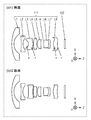
- Lens arrangement diagram showing an infinitely focused state of the lens system according to Embodiment 1 Lens arrangement diagram showing infinite focus state of lens system according to Embodiment 2
- Lens arrangement diagram showing an infinitely focused state of the lens system according to Embodiment 3 Schematic diagram of photosensitive surface of image sensor according to Embodiments 1 to 3
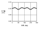
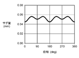
- the figure which shows the relationship between the sag amount of the free-form surface lens of the lens system which concerns on Embodiment 1, and the angle (phase) around an optical axis The figure which shows the relationship between the sag amount of the free-form surface lens of the lens system which concerns on Embodiment 2, and the angle (phase) around an optical axis.
- FIG. 1 The figure which shows the relationship between the sag amount of the free-form surface lens of the lens system which concerns on Embodiment 3, and the angle (phase) around an optical axis.
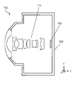
- Schematic configuration diagram of a camera system according to Embodiment 4 Schematic configuration diagram of an imaging system according to Embodiment 5
- Aberration diagram showing spherical aberration and field curvature of infinitely focused state of lens system according to Numerical Example 1 The figure which shows the relationship between the field angle of an infinite focus state of a lens system which concerns on Numerical Example 1, and an image point.
- FIG. 1 is a layout diagram of a lens system according to Embodiment 1, and represents an infinitely focused state.
- FIG. 1A is a YZ cross section
- FIG. 1B is an XZ cross section, and includes a lens system 111 having eight lens elements, and a rectangular imaging element 102 having a short side and a long side.
- the X direction is a direction parallel to the long side of the image sensor 102
- the Y direction is a direction parallel to the short side direction of the image sensor 102
- the Z direction is a direction parallel to the optical axis.
- the YZ cross section is a plane including the optical axis and parallel to the Y direction and the Z direction.
- the XZ cross section is a plane including the optical axis and parallel to the X direction and the Z direction.
- the lens system 111 includes five lens elements L1 to L5, an aperture stop A, and three lens elements L6 to L8 in order from the object side to the image plane side. Prepare.
- the imaging position of the lens system 111 is the image plane of the image sensor 102.
- the reference numerals are omitted.
- the lens system 111 includes, in order from the object side to the image plane side, a negative meniscus lens element L1 having a convex surface directed toward the object side, a biconcave lens element L2, a biconcave lens element L3, Convex lens element L4, positive meniscus lens element L5 having both aspherical surfaces with the convex surface facing the object side, aperture stop A, biconvex lens element L6, and image surface side
- a negative meniscus lens element L7 having a convex surface and a positive meniscus lens element L8 having a convex surface facing the object side.
- the lens element L6 and the lens element L7 are cemented.
- the lens element L1 is an example of a first lens element
- the lens element L2 is an example of a second lens element.
- the lens element L3 and the lens element L8 are both XY polynomial free-form surfaces on the object side and the image plane side.
- the free-form surface is marked with *.
- the lens element L3 is an example of a first free-form surface lens
- the lens element L8 is an example of a second free-form surface lens.
- the XZ plane in which the sag amount in each circle of the free-form surface on the image plane side of the lens element L8 separated from the optical axis by a length of 40% or more of the shortest image height passes through the optical axis and is parallel to the long side of the image sensor 102.
- the sag amount is parallel to the optical axis from the reference surface to a certain point on the surface of the lens element when a plane orthogonal to the optical axis including the intersection with the surface of the lens element is used as the reference surface. The distance in the direction.
- the mathematical expression indicating the sag amount and the surface data of each lens element will be described later.
- the shape of the surface of the free-form surface lens and the aspherical lens is expressed by the shape in the vicinity (vertex) of the optical axis in the Y direction.
- FIG. 2 is a layout diagram of lens systems according to the second embodiment.
- 2A is a YZ cross section
- FIG. 2B is an XZ cross section, showing a lens system 121 composed of eight lens elements and a rectangular imaging element 102 having short and long sides. Yes.
- the reference numerals are omitted.
- the lens system 121 of the second embodiment has the same number of lens elements, types, and arrangement order as the lens system 111 of the first embodiment, but the surface data of the lens system elements L1 to L8 is different. Differences in the plane data will be described later.
- the lens element L1 is an example of the first lens element
- the lens element L2 is an example of the second lens element
- the lens element L3 is an example of the first free-form surface lens
- the lens element L8 is the first lens element L8. It is an example of a 2 free-form surface lens.
- the sag amount of the free curved surface on the image plane side of the lens element L8 in each circle separated by 20% or more of the shortest image height from the optical axis passes through the optical axis.
- An XZ plane (first surface) parallel to the long side of 102 and an YZ plane (second surface) passing through the optical axis and parallel to the short side of the image sensor 102 have extreme values.
- FIG. 3 is a layout diagram of lens systems according to the third embodiment.
- 3A is a YZ cross section
- FIG. 3B is an XZ cross section, showing a lens system 131 having seven lens elements and a rectangular imaging element 102 having short and long sides. .
- the reference numerals are omitted.
- the lens system 131 of the third embodiment differs from the lens system 111 of the first embodiment in the number of lens elements (seven) and the surface data of the lens system elements L1 to L7.
- the lens system 131 includes four lens elements L1 to L4, an aperture stop A, and three lens elements L5 to L7 in order from the object side to the image plane side. Prepare.
- the imaging position of the lens system 131 is the image plane of the image sensor 102. Differences in the plane data will be described later.
- the lens system 131 includes, in order from the object side to the image plane side, a negative meniscus lens element L1 having a convex surface directed toward the object side, a biconcave lens element L2 having both surfaces formed of aspheric surfaces, and a biconcave lens.
- a negative meniscus lens element L6 having an aspheric surface on the image surface and a convex surface facing the image surface, and a biconvex lens element L7.
- the lens element L5 and the lens element L6 are cemented.
- the lens element L1 is an example of a first lens element
- the lens element L2 is an example of a second lens element.
- the lens element L3 has an XY polynomial free-form surface on the object side and an aspheric surface on the image plane side.
- the lens element L7 is an XY polynomial free-form surface on both the object side and the image plane side. In FIG. 3, the free curved surface is marked with *.
- the lens element L3 is an example of a first free-form surface lens
- the lens element L7 is an example of a second free-form surface lens.
- the sag amount of a free-form surface on the object side of the lens element L7 in a circle separated by 30% or more of the shortest image height from the optical axis passes through the optical axis and is parallel to the long side and the short side of the image sensor 102 ( It has an extreme value other than the intersection with the YZ plane (second plane) passing through the first plane) and the optical axis and parallel to the short side of the image sensor 102.
- the lens systems according to Embodiments 1 to 3 have a plurality of lens elements and form an image on a rectangular imaging element 102 having a short side and a long side.
- the lens system includes a free-form surface lens that is rotationally asymmetric with respect to the optical axis as a lens element, and includes a plurality of lens elements, an aperture stop, and a plurality of lens elements in order from the object side to the image plane side. ing. With this configuration, it is possible to form a substantially rectangular image close to a rectangle.
- the lens systems according to Embodiments 1 to 3 have a configuration having at least three or more lens elements that are rotationally symmetric with respect to the optical axis. With this configuration, it is possible to reduce the number of free-form surface lenses and to reduce the performance bias depending on the direction. Further, the lens systems according to Embodiments 1 to 3 have an advantage that the calculation time can be shortened at the time of design.
- the lens systems according to Embodiments 1 to 3 are configured to include, in order from the object side, a lens element L1 that is a meniscus having a negative power convex toward the object side, and a lens element L2 that has a negative power. .
- a lens element L1 that is a meniscus having a negative power convex toward the object side
- a lens element L2 that has a negative power.
- the lens systems according to Embodiments 1 to 3 are fisheye lenses having a half angle of view of 80 ° or more, they can cover a wide angle of view. In general, in the case of a fisheye lens, it is difficult to form an image near the diagonal of the image sensor. However, by using the free-form surface lens according to the present disclosure, it is possible to form an image near the diagonal of the image sensor.
- a lens system that forms an image on a rectangular imaging device disposed on the optical axis and includes a free-form surface lens that is asymmetric with respect to the optical axis
- the sag amount of the free-form surface of the free-form surface lens in a circle separated by 40% or more of the shortest image height from the optical axis passes through the XZ plane and the optical axis that pass through the optical axis and parallel to the long side of the image sensor. It is preferable to have an extreme value other than the intersection with the YZ plane parallel to the short side of the image sensor (this configuration is hereinafter referred to as a basic configuration of the embodiment).
- the shortest image height indicates the shortest of the distance on the image plane from the image point by the light beam perpendicularly incident on the image sensor 102 to the end of the image circle formed by the lens system.
- the image sensor 102 has the shortest image height in the short side direction.
- the sag amount of the surface of the free-form surface lens has an extreme value other than the intersection with the XZ plane and the YZ plane, the image can be easily enlarged particularly in the direction near the diagonal of the image sensor 102.
- the range from the optical axis having the extreme value is 40% or more of the shortest image height in the radial direction, so that a good image enlargement effect can be obtained.
- the sag amount in a circle separated by 40% or more of the shortest image height is an XZ plane and a YZ plane that pass through the optical axis and are parallel to the long side and the short side of the image sensor.
- the area of the photosensitive surface of the rectangular image sensor cannot be fully utilized.
- the number of lens elements increases, leading to an increase in the size of the lens system. If the sag amount of the free-form surface in a circle 40 to 80% of the shortest image height from the optical axis has an extreme value other than the intersection with the XZ plane and YZ plane, the above effect is further achieved. Can be made.
- FIG. 4 is a schematic view of the photosensitive surface of the image sensor.
- the entire surface of the image sensor 102 on the lens system side is a photosensitive surface.
- the part is removed.
- the intersection O between the optical axis of the lens system and the photosensitive surface of the image sensor 102 is the center of the photosensitive surface of the image sensor 102.
- the region of the photosensitive surface of the imaging device 102 can be utilized most effectively.
- the angle is in the range of ⁇ ⁇ 25 °, a substantially rectangular image can be formed.
- the angle ⁇ is an angle formed by a line segment OC1 connecting the intersection point O and the corner C1 with the X axis.
- the angle ⁇ is shown for the first quadrant where the line segment OC1 is located.
- the line segments OC2, OC3, and OC4 are respectively The same applies to the second to fourth quadrants located.
- FIG. 5 shows the sag amount of the free-form surface on the image plane side of the lens element L8 of the lens system 111 according to Embodiment 1, and the angle around the optical axis in a circle that is 60% of the shortest image height away from the optical axis.
- the relationship with (phase) is shown.
- 6 shows the sag amount of the free-form surface on the image plane side of the lens element L8 of the lens system 121 according to Embodiment 2, and the angle around the optical axis in a circle 60% of the shortest image height away from the optical axis.
- the relationship with (phase) is shown.
- FIGS. 5 to 7 show the sag amount of the free curved surface on the object side of the lens element L7 of the lens system 131 according to Embodiment 3, and the angle around the optical axis in a circle that is 60% of the shortest image height away from the optical axis ( (Phase).
- FIGS. 5 to 7 show the sag amount in the entire circumference (that is, the first to fourth quadrants) of a circle separated by 60% of the shortest image height from the optical axis.
- the sag amount shown in the first quadrant (phase 0 ° to 90 °) and the third quadrant (phase 180 ° to 270 °) is the same, and the second quadrant (phase 90 ° to 90 °) is the same.
- 180 °) and the sag amount shown in the fourth quadrant (phase 270 ° to 360 °) are the same.
- the sag amounts shown in the first quadrant and the second quadrant are symmetric with respect to the phase 90 °
- the sag amounts shown in the second quadrant and the third quadrant are symmetric with respect to the phase 180 °
- the sag amount shown in the fourth quadrant is symmetric about the phase 270 °
- the sag amount shown in the fourth quadrant and the first quadrant is symmetric about the phase 360 °.
- the phases 0 ° and 180 ° correspond to the position of the XZ plane (first surface) passing through the optical axis and parallel to the long side of the image sensor 102
- the phases 90 ° and 270 ° are taken through the optical axis. This corresponds to the position of the YZ plane (second surface) parallel to the short side of the element 102.
- the extreme values of the first quadrant of the sag amount in the lens systems 111, 121, and 131 shown in FIGS. 5 to 7 are a phase of about 38 °, about 49 °, and about 42 °, respectively.
- the lens systems in Embodiments 1 to 3 have a range of ⁇ 25 ° with respect to the respective directions from the intersection O between the optical axis and the photosensitive surface of the image sensor 102 to the corners C1 to C4 of the photosensitive surface. It is designed to have an extreme value of the sag amount.
- the angle ⁇ in the first quadrant will be described, but the same applies to the second to fourth quadrants.
- the lens system is designed as follows depending on the aspect ratio between the long side and the short side of the photosensitive surface of the image sensor 102, for example.
- the ratio of the long side to the short side of the photosensitive surface of the image sensor 102 is a to b, tan ⁇ 1 (b / a) ⁇ 25 ° with respect to the direction parallel to the long side of the image sensor 102 (X direction).
- the extreme value of the sag amount is in the range of. For example, when the ratio of the long side to the short side of the image sensor 102 is 16: 9, the sag amount has an extreme value in the range of phase 29 ⁇ 25 °.
- the ratio of the long side to the short side of the image sensor 102 is 4 to 3, the phase from the X direction has an extreme value of the sag amount in the range of 37 ⁇ 25 °.
- a lens system having an extreme value of the sag amount in a range of 33 ⁇ 21 ° with respect to the X direction which is a common range of the range 29 ⁇ 25 ° and the range of 37 ⁇ 25 ° with respect to the X direction, has an aspect ratio. It can be used for both 16 to 9 and 4 to 3 image sensors.
- the sag amount has an extreme value means that the sag amount is reversed on a circle separated from the optical axis by a predetermined distance, but at least 3% of the maximum sag amount on the circle is reversed. Is preferred. Although it has been difficult to produce a lens having such a free-form surface, it has become possible to produce a lens with the recent progress in processing and molding technology.
- the lens system having the basic configuration of the present embodiment satisfies the following condition (1).
- ⁇ LONG > 60 ° (1) here, ⁇ LONG : Maximum half field angle in the long side direction of the image sensor Condition (1) is a condition for defining the half field angle of the lens system. If the lower limit of the condition (1) is not reached, the angle of view of the lens system becomes narrow, the image circle can be close to a rectangle without having the basic configuration of the present embodiment, and the area of the photosensitive surface of the rectangular image sensor 102 can be reduced. It becomes easy to use effectively and deviates from the intention of the present application. In addition, it becomes difficult to control spherical aberration.
- a lens system having the basic configuration of the present embodiment such as the lens systems according to Embodiments 1 to 3, preferably satisfies the following condition (2).
- D LSHORT Long-side direction between an image point with respect to incident light in the long-side direction of the image sensor and an image point with respect to incident light perpendicular to the image-capturing element having an angle of view equal to the maximum half field angle in the short-side direction of the image-capturing element
- D SHORT Maximum distance in the short side direction between the image point with respect to incident light having the maximum half angle of view in the short side direction of the image sensor and the image point with respect to incident light perpendicular to the image sensor.
- the lens system having the basic configuration of the present embodiment satisfies the following condition (3).
- ⁇ LONG Maximum half angle of view in the long side direction of the image sensor
- ⁇ SHORT Maximum half angle of view in the short side direction of the image sensor
- D LLONG Image point and imaging for incident light of the maximum half angle of view in the long side direction of the image sensor
- D SSHORT The image point with respect to the incident light having the maximum half angle of view in the short side direction of the image sensor and the image point with respect to incident light perpendicular to the image sensor
- the maximum distance condition (3) in the short side direction is a condition for defining the ratio between the maximum half field angle and the image height in the short side direction and the long side direction of the image sensor.
- the angle of view in the short side direction becomes too wide compared to the angle of view in the long side direction, making it difficult to control imaging performance, particularly field curvature.
- the image circle becomes too long in the long side direction, and it becomes difficult to effectively use the area of the photosensitive surface of the rectangular image sensor 102.
- the upper limit of the condition (3) is exceeded, the angle of view in the long side direction becomes too wide compared to the angle of view in the short side direction, making it difficult to control the imaging performance, particularly the field curvature.
- the image circle becomes too long in the short side direction, and it becomes difficult to effectively use the region of the photosensitive surface of the rectangular image sensor 102.
- the lens system having the basic configuration of the present embodiment satisfies the following condition (4).
- the lens system having the basic configuration of the present embodiment satisfies the following condition (5).
- L Total optical length of the lens system
- Fno. F value of the lens system
- D LLONG Maximum distance in the long side direction between the image point with respect to the incident light having the maximum half angle of view in the long side direction of the image sensor and the image point with respect to the incident light perpendicular to the image sensor
- the condition (5) is This is a condition that defines the relationship between the total optical length of the lens system, the F value of the lens system, and the image height in the long side direction. If the upper limit of the condition (5) is exceeded, the lens system becomes excessively large with respect to the F value of the lens system and the image circle, so that the size reduction cannot be achieved, and in addition, the control of the field curvature becomes difficult.
- the lens system having the basic configuration of the present embodiment satisfies the following condition (6).
- n FREE Refractive index with respect to d-line of free-form surface lens
- Condition (6) is a condition that defines the refractive index with respect to d-line of a free-form surface lens. If the upper limit of the condition (6) is exceeded, the refractive index of the free-form surface lens becomes too high, and it becomes difficult to control astigmatism because the rays are bent sharply. This condition can be obtained even when one free-form surface lens in the lens system is satisfied, and when a plurality of free-form surface lenses are satisfied, the effect can be further achieved. .
- the lens system having the basic configuration of the present embodiment has the aperture stop A between the object and the image sensor, and the following condition (7) Is preferably satisfied.
- N o Number of lens elements on the object side of the aperture stop
- N i Number of lens elements on the image plane side of the aperture stop
- Condition (7) is a condition that defines the number of lens elements before and after the aperture stop A. is there. If the lower limit of condition (7) is not reached, the number of lens elements on the image plane side with respect to the aperture stop A will increase too much, leading to an increase in the size of the lens system in the optical axis direction. In addition, the number of lens elements on the object side is smaller than that of the aperture stop A, making it difficult to control field curvature.
- the lens system having the basic configuration of the present embodiment has an aperture stop A between the object and the image sensor 102, and the object is more than the aperture stop A. It is preferable to have at least one first free-form surface lens on the side and at least one second free-form surface lens on the image plane side from the aperture stop A.
- the image circle of the lens system is not included in the image sensor 102.
- the image sensor is prevented from being included in the image sensor 102. It is possible to ensure good imaging performance on 102.
- Each lens element constituting the lens system according to Embodiments 1 to 3 is a refractive lens element that deflects incident light by refraction (that is, a type in which deflection is performed at an interface between media having different refractive indexes).
- Lens element a refractive lens element that deflects incident light by diffraction
- a refractive / diffractive hybrid lens element that deflects incident light by a combination of diffractive action and refractive action
- a refractive index that deflects incident light according to the refractive index distribution in the medium
- Each lens system may be composed of a distributed lens element or the like.
- Each lens constituting the lens system according to Embodiments 1 to 3 has a symmetric surface with respect to the long side or the short side of the image sensor 102, but even when an asymmetric surface is used, If the basic configuration of the present embodiment and each condition are satisfied, sufficient effects can be obtained.
- FIG. 8 is a schematic configuration diagram of a camera system according to the fourth embodiment.
- a camera system 100 according to Embodiment 4 includes a lens system 111, an image sensor 102 that receives an optical image formed by the lens system 111 and converts it into an electrical image signal, and a camera body 103.
- the lens system of Embodiment 4 the lens system according to any of Embodiments 1 to 3 can be used.
- FIG. 8 illustrates a case where the lens system 111 according to Embodiment 1 is used as the lens system.
- a substantially rectangular image can be formed on the image sensor 102, and the photosensitive surface area of the rectangular image sensor 102 can be formed. It is possible to realize a camera system 100 that can obtain an image that effectively utilizes the above.
- FIG. 9 is a schematic configuration diagram of an imaging system according to the fifth embodiment.
- the imaging optical system 201 used in the imaging system 200 according to the fifth embodiment includes the lens system according to any one of the first to third embodiments, like the camera system 100 according to the fourth embodiment.
- the image processing unit 202 By processing an image obtained by the imaging optical system 201 by the image processing unit 202, it is possible to transform and process the image into an image applicable to various applications.
- the image processing unit 202 may be inside or outside the camera body 103 (see FIG. 8).
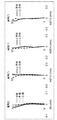
- FIG. 10 is a spherical aberration diagram and an astigmatism diagram of the lens system 111 according to Numerical Example 1 in an infinite focus state, and images are taken in order from the left side.
- Spherical aberration SA
- astigmatism AST-V
- astigmatism AST-H
- astigmatism in the diagonal direction (AST-D)
- the horizontal axis represents spherical aberration
- the vertical axis represents pupil height.
- the solid line is the d line, the short broken line is the C line, and the long broken line is the F line characteristic.
- the horizontal axis represents astigmatism and the vertical axis represents the angle of view.
- the solid line is the characteristic of the YZ plane (y direction in the figure), and the broken line is the characteristic of the XZ plane (x direction in the figure).
- Embodiment 1 uses only the even terms of x and y in the XY polynomial, the astigmatism AST-D in the diagonal direction is the same in any direction because it is symmetric with respect to the x axis and the y axis. Become.
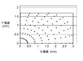
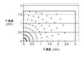
- FIG. 11 is a diagram showing the relationship between the angle of view and the image point in the infinitely focused state of the lens system 111 according to Numerical Example 1.
- FIG. 11 plots image points every 10 ° of the angle of view in the first quadrant of the image plane with the optical axis as the origin (0, 0).
- Other quadrants have a relationship with the first quadrant that is symmetric with respect to the vertical and horizontal axes. It can be seen that the shape of the image plane is enlarged compared to a normal rotationally symmetric lens, and the area of the photosensitive surface of the rectangular image sensor 102 can be effectively utilized.
- the lens system 111 of Numerical Example 1 corresponds to Embodiment 1 shown in FIG.
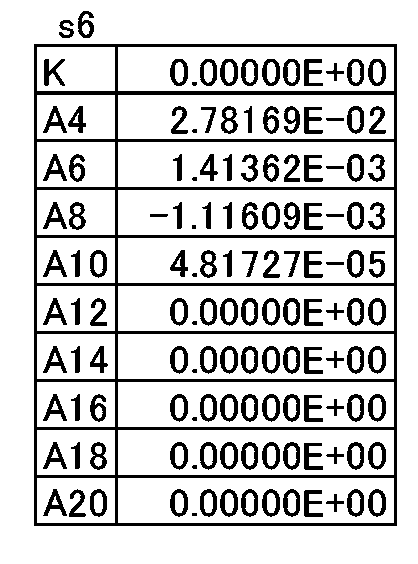
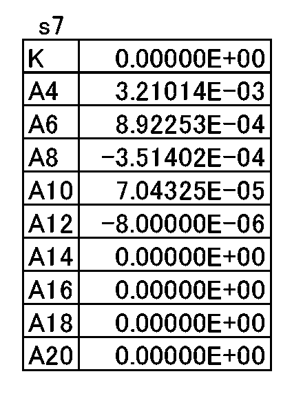
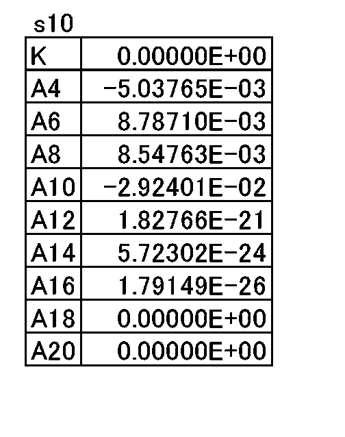
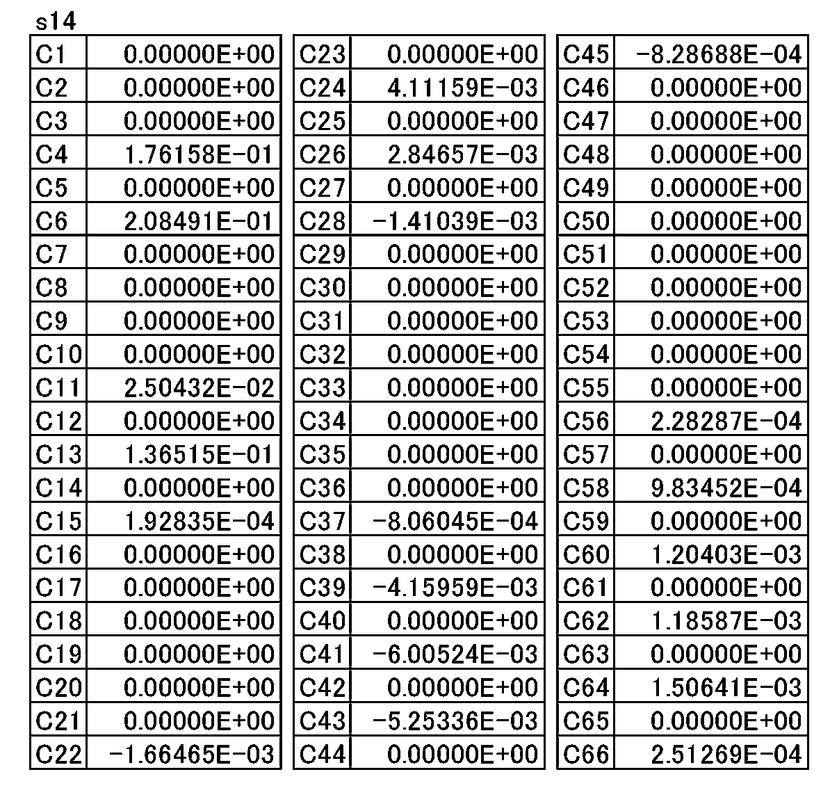
- Surface data of the lens system 111 of Numerical Example 1 are shown in Table 1, various data are shown in Table 2, and the fifth, sixth, ninth, tenth, fifteenth, and sixteenth surfaces are aspheric.
- Free surface data is shown in Table 3, Table 4, Table 5, Table 6, Table 7 and Table 8, respectively.
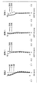
- FIG. 12A and 12B are a spherical aberration diagram and an astigmatism diagram of the lens system 121 according to Numerical Example 2 in an infinitely focused state.
- FIG. 13 is a diagram showing the relationship between the angle of view and the image point in the infinitely focused state of the lens system 121 according to Numerical Example 2.
- the lens system 121 of Numerical Example 2 corresponds to the second embodiment shown in FIG.
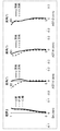
- FIG. 14 is a spherical aberration diagram and an astigmatism diagram of the lens system 131 according to Numerical Example 3 in an infinitely focused state.
- FIG. 15 is a diagram showing the relationship between the angle of view and the image point in the infinitely focused state of the lens system 131 according to Numerical Example 3.
- the lens system 131 of Numerical Example 3 corresponds to Embodiment 3 shown in FIG.
- Table 17 Surface data of the lens system 131 of Numerical Example 3 are shown in Table 17, various data are shown in Table 18, the third surface, the fourth surface, the fifth surface, the sixth surface, the seventh surface, the tenth surface, and the twelfth surface.
- Table 19 Table 20, Table 21, Table 22, Table 23, Table 24, Table 25, Table 26 and Table 27 show the aspherical surface and free-form surface data of the 13th surface and the 14th surface, respectively.
- Table 28 shows the corresponding values for each condition in the lens system of each numerical example.
- the lens system according to the present embodiment is applicable to digital still cameras, digital video cameras, mobile phone device cameras, PDA (Personal Digital Assistance) cameras, surveillance cameras in surveillance systems, web cameras, in-vehicle cameras, etc. It is suitable for a photographing optical system that requires high image quality, such as a digital still camera system and a digital video camera system.
- the lens system according to the present embodiment is provided in a digital video camera system among the interchangeable lens apparatuses according to the present embodiment.
Landscapes
- Physics & Mathematics (AREA)
- General Physics & Mathematics (AREA)
- Optics & Photonics (AREA)
- Lenses (AREA)
Abstract
Description
図1は、実施の形態1に係るレンズ系の配置図であり、無限遠合焦状態を表している。
図2は、実施の形態2に係るレンズ系の配置図である。図2の(a)はYZ断面で、図2の(b)はXZ断面で、8枚のレンズ素子からなるレンズ系121と、短辺と長辺を有する矩形の撮像素子102とを表している。図2の(b)では符号を省略している。実施の形態2のレンズ系121は、実施の形態1のレンズ系111と比較して、レンズ素子の枚数、種類及び配置順が同じで、各レンズ系素子L1~L8の面データが異なる。面データの相違点については、後述する。レンズ系121において、レンズ素子L1は第1レンズ素子の一例であり、レンズ素子L2は第2レンズ素子の一例であり、レンズ素子L3は第1自由曲面レンズの一例であり、レンズ素子L8は第2自由曲面レンズの一例である。
図3は、実施の形態3に係るレンズ系の配置図である。図3の(a)はYZ断面、図3の(b)はXZ断面で、7枚のレンズ素子を有するレンズ系131と、短辺と長辺を有する矩形の撮像素子102とを表している。図3の(b)では符号を省略している。実施の形態3のレンズ系131は、実施の形態1のレンズ系111と比較して、レンズ素子の枚数(7枚)及び各レンズ系素子L1~L7の面データが異なる。
実施の形態1~3に係るレンズ系は、複数枚のレンズ素子を有し、短辺と長辺を有する矩形の撮像素子102に結像させる。そして、レンズ系は、レンズ素子として光軸に対して回転非対称である自由曲面レンズを含み、物体側から像面側へと順に、複数枚のレンズ素子、開口絞り、複数枚のレンズ素子を備えている。この構成により、矩形に近い略矩形の像を結像することが可能となる。
ここで、
ωLONG:撮像素子の長辺方向の最大半画角
条件(1)は、レンズ系の半画角を規定するための条件である。条件(1)の下限を下回ると、レンズ系の画角が狭くなり、本実施の形態の基本構成を有しなくともイメージサークルが矩形に近くでき、矩形の撮像素子102の感光面の領域を有効活用しやすくなり、本願の意図と乖離してくる。また、球面収差の制御が困難となる。
ωLONG>90° ・・・(1)’’
例えば、実施の形態1~3に係るレンズ系のように、本実施の形態の基本構成を有するレンズ系は、以下の条件(2)を満足することが好ましい。
ここで、
DLSHORT:撮像素子の短辺方向の最大半画角と等しい画角の、撮像素子の長辺方向の入射光に対する像点と、撮像素子に垂直な入射光に対する像点との長辺方向の最大距離
DSSHORT:撮像素子の短辺方向の最大半画角の入射光に対する像点と撮像素子に垂直な入射光に対する像点との短辺方向の最大距離
条件(2)は、撮像素子の短辺方向の最大半画角の入射光に対する像点について、撮像素子の短辺方向の像高よりも、長辺方向の像高の方が長くなることを規定するための条件である。条件(2)の下限を下回ると、矩形の撮像素子102の感光面の領域の有効活用が困難になる。または、像面湾曲の制御が困難になる。
1.6<DLSHORT/DSSHORT ・・・(2)’’
例えば、実施の形態1~3に係るレンズ系のように、本実施の形態の基本構成を有するレンズ系は、以下の条件(3)を満足することが好ましい。
ここで、
ωLONG:撮像素子の長辺方向の最大半画角
ωSHORT:撮像素子の短辺方向の最大半画角
DLLONG:撮像素子の長辺方向の最大半画角の入射光に対する像点と撮像素子に垂直な入射光に対する像点との長辺方向の最大距離
DSSHORT:撮像素子の短辺方向の最大半画角の入射光に対する像点と撮像素子に垂直な入射光に対する像点との短辺方向の最大距離
条件(3)は、撮像素子の短辺方向と長辺方向の、最大半画角と像高の比を規定するための条件である。条件(3)の下限を下回ると、短辺方向の画角が長辺方向の画角に比較して広くなりすぎ、結像性能、特に像面湾曲の制御が困難になる。あるいはイメージサークルが長辺方向に長くなりすぎ、矩形の撮像素子102の感光面の領域の有効活用が困難になる。条件(3)の上限を上回ると、長辺方向の画角が短辺方向の画角に比較して広くなりすぎ、結像性能、特に像面湾曲の制御が困難になる。あるいはイメージサークルが短辺方向に長くなりすぎ、矩形の撮像素子102の感光面の領域の有効活用が困難になる。
0.6 <DSSHORT×ωLONG/(DLLONG×ωSHORT)<0.8 ・・・(3)’’
例えば、実施の形態1~3に係るレンズ系のように、本実施の形態の基本構成を有するレンズ系は、以下の条件(4)を満足することが好ましい。
ここで、
ωLONG:撮像素子の長辺方向の最大半画角
ωSHORT:撮像素子の短辺方向の最大半画角
条件(4)は、最大半画角について、撮像素子の長辺方向と短辺方向の差を規定する条件である。条件(4)の下限を下回ると、短辺方向の画角が長辺方向の画角に比較して等しい、あるいは大きくなってしまい、極めていびつな形状で結像してしまうことになり、画角あたりの解像度が長辺方向と短辺方向で大きく変わってしまう。また、球面収差が長辺方向と短辺方向で大きく変化してしまい、制御が困難になる。
例えば、実施の形態1~3に係るレンズ系のように、本実施の形態の基本構成を有するレンズ系は、以下の条件(5)を満足することが好ましい。
ここで、
L:レンズ系の光学全長
Fno.:レンズ系のF値
DLLONG:撮像素子の長辺方向の最大半画角の入射光に対する像点と撮像素子に垂直な入射光に対する像点との長辺方向の最大距離
条件(5)は、レンズ系の光学全長とレンズ系のF値、長辺方向の像高の関係を規定する条件である。条件(5)の上限を上回ると、レンズ系のF値、イメージサークルに対してレンズ系が肥大化しすぎ、小型化を達成できず、加えて像面湾曲の制御が困難となる。
L×Fno./DLLONG<25 ・・・(5)’’
例えば、実施の形態1~3に係るレンズ系のように、本実施の形態の基本構成を有するレンズ系は、以下の条件(6)を満足することが好ましい。
ここで、
nFREE:自由曲面レンズのd線に対する屈折率
条件(6)は、自由曲面レンズのd線に対する屈折率を規定する条件である。条件(6)の上限を上回ると、自由曲面レンズの屈折率が高くなりすぎ、急激に光線を曲げることから非点収差の制御が困難になる。なお、本条件はレンズ系の中の1枚の自由曲面レンズが満足していても効果を得られるし、複数枚の自由曲面レンズが満足している場合は、さらに効果を奏功させることができる。
例えば、実施の形態1~3に係るレンズ系のように、本実施の形態の基本構成を有するレンズ系は、物体と撮像素子との間に開口絞りAを有し、以下の条件(7)を満足することが好ましい。
ここで、
No:開口絞りよりも物体側のレンズ素子の枚数
Ni:開口絞りよりも像面側のレンズ素子の枚数
条件(7)は、開口絞りA前後のレンズ素子の枚数差を規定する条件である。条件(7)の下限を下回ると、開口絞りAよりも像面側のレンズ素子の枚数が増えすぎ、レンズ系の光軸方向の大型化を招いてしまう。また、開口絞りAよりも物体側のレンズ素子の枚数が少なく、像面湾曲の制御が困難となる。条件(7)の上限を上回ると、開口絞りAよりも物体側のレンズ素子の枚数が増えすぎ、レンズ系の径方向への大型化を招いてしまう。また、開口絞りAよりも像面側のレンズ素子の枚数が少なく、球面収差の制御が困難となる。
例えば、実施の形態1~3に係るレンズ系のように、本実施の形態の基本構成を有するレンズ系は、物体と撮像素子102との間に開口絞りAを有し、開口絞りAより物体側に少なくとも1枚の第1自由曲面レンズを有し、開口絞りAより像面側に少なくとも1枚の第2自由曲面レンズを有することが好ましい。本構成を採ることで、長辺方向、短辺方向、対角方向、いずれの方向でも像面湾曲を小さくすることができるという利点がある。
図8は実施の形態4に係るカメラシステムの概略構成図である。実施の形態4に係るカメラシステム100は、レンズ系111と、レンズ系111によって形成される光学像を受光して、電気的な画像信号に変換する撮像素子102と、カメラ本体103を含む。実施の形態4のレンズ系は、実施の形態1~3いずれかに係るレンズ系を用いることができる。図8は、レンズ系として実施の形態1に係るレンズ系111を用いた場合を図示している。
図9は実施の形態5に係る撮像システムの概略構成図である。実施の形態5に係る撮像システム200に用いられている撮像光学系201は、実施の形態4のカメラシステム100のように、実施の形態1~3いずれかに係るレンズ系を含んでいる。撮像光学系201で得られた画像を、画像処理部202で処理することで、さまざまなアプリケーションに応用可能な画像に変形、加工することが可能となる。なお、画像処理部202はカメラ本体103(図8参照)の内部または外部のどちらにあっても良い。
以下、実施の形態1に係るレンズ系111を具体的に実施した数値実施例1を説明する。なお、数値実施例1において、図や表中の長さの単位は「mm」であり、画角の単位は「°」である。また、数値実施例1において、曲率半径r、面間隔d、d線に対する屈折率nd、d線に対するアッベ数νdを示す。非球面及び自由曲面のZ軸に平行な面のサグ量zはそれぞれ、数式1及び数式2で定義している。

h:径方向の高さ
k:コーニック定数
An:n次の非球面係数

c:頂点曲率
k:コーニック定数
cj:係数
図10は、数値実施例1に係るレンズ系111の無限遠合焦状態の球面収差図及び非点収差図であり、左側から順に、撮像素子102の短辺方向の球面収差(SA)、非点収差(AST―V)、撮像素子102の長辺方向の非点収差(AST―H)、対角方向の非点収差(AST―D)を示す。球面収差の図において、横軸は球面収差を、縦軸は瞳高さを表している。そして、実線はd線、短破線はC線、長破線はF線の特性である。非点収差の図において、横軸は非点収差を、縦軸は画角を表している。そして、実線はYZ平面(図中、y方向)、破線はXZ平面(図中、x方向)の特性である。

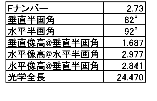

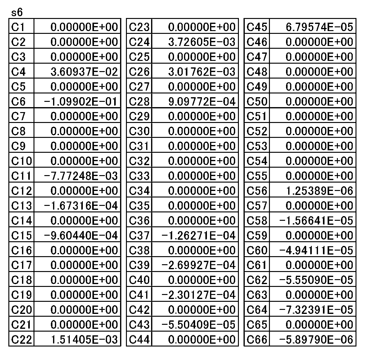
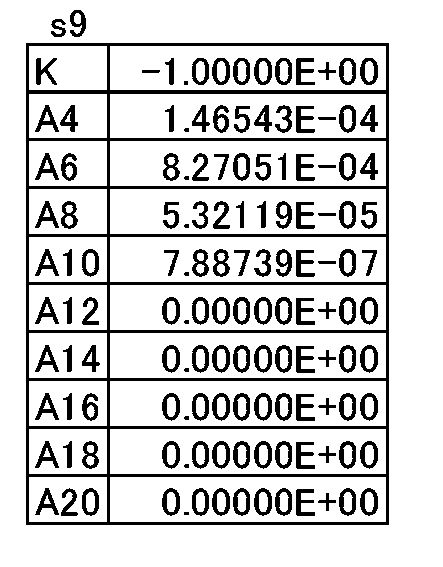


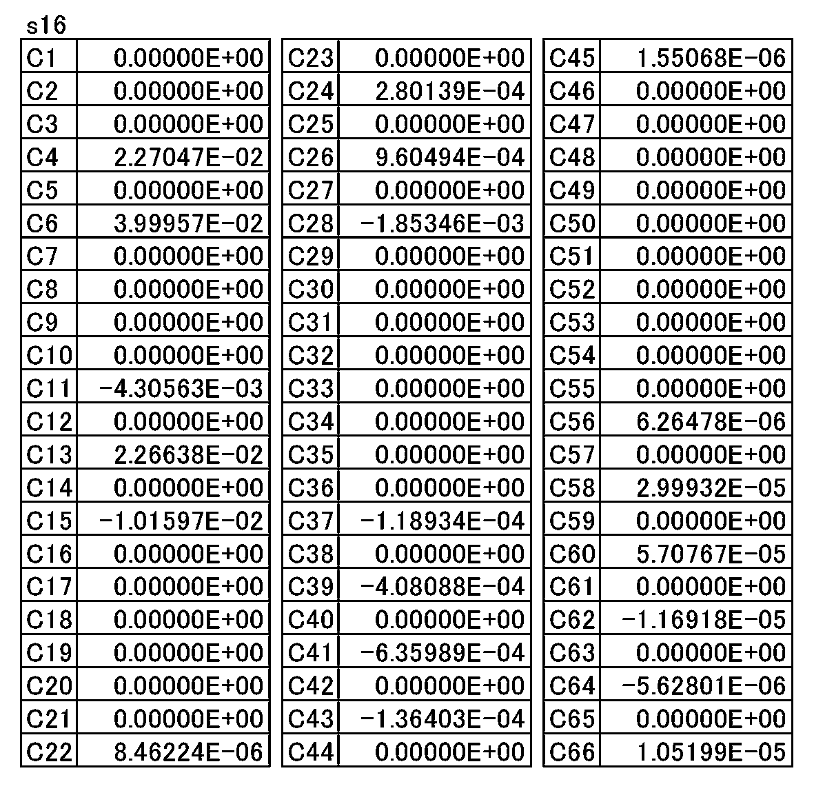
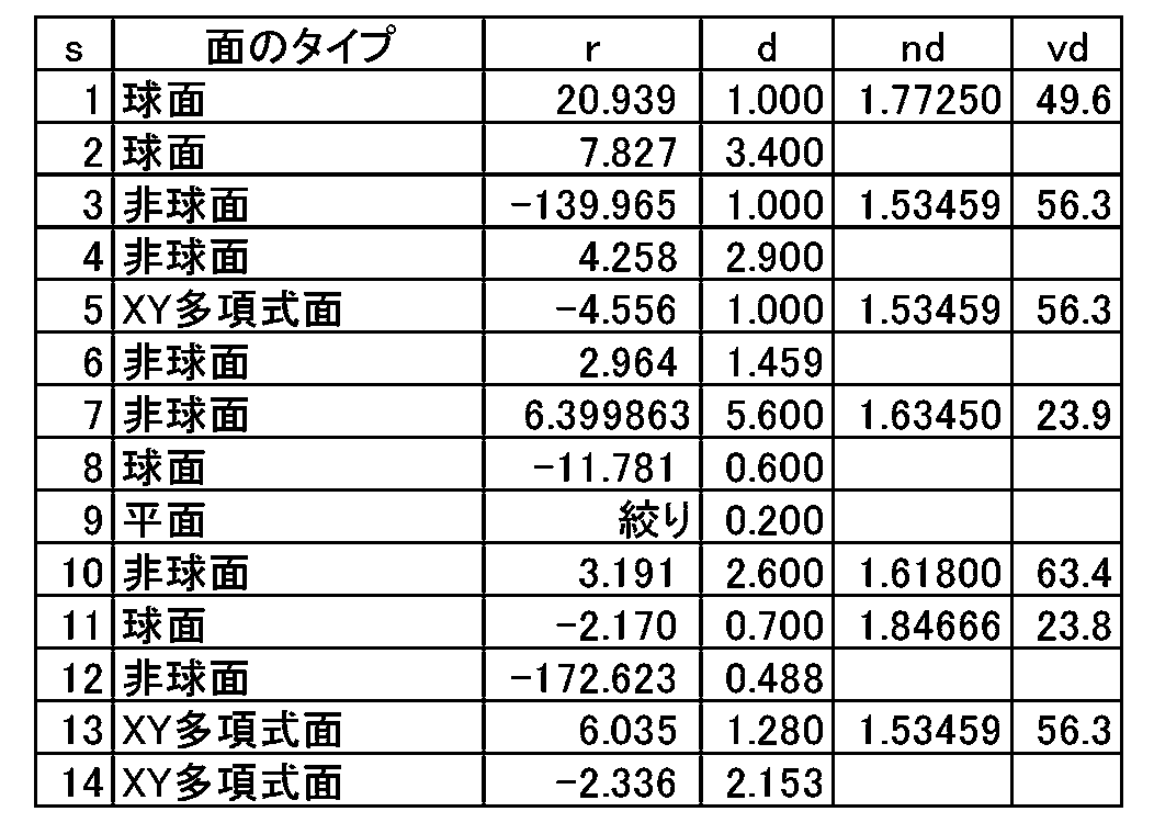
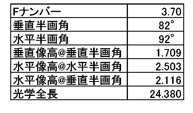
図12は、数値実施例2に係るレンズ系121の無限遠合焦状態の球面収差図及び非点収差図である。また、図13は、数値実施例2に係るレンズ系121の無限遠合焦状態の画角と像点の関係を示した図である。図13に示すレンズ系121の場合も、通常の回転対称レンズに比較して、像面の形状が拡大され、矩形の撮像素子102の感光面の領域を有効活用できていることが分かる。数値実施例2のレンズ系121は、図2に示した実施の形態2に対応する。数値実施例2のレンズ系121の面データを表9に、各種データを表10に、第5面、第6面、第9面、第10面、第15面、および第16面の非球面・自由曲面データをそれぞれ表11、表12、表13、表14、表15および表16に示す。


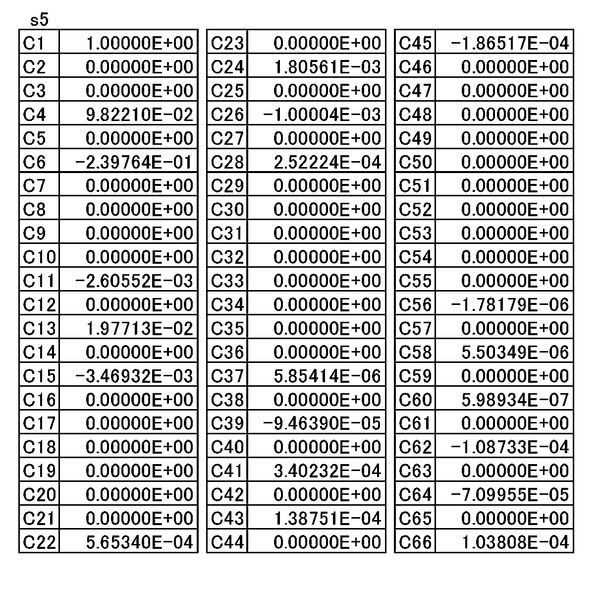
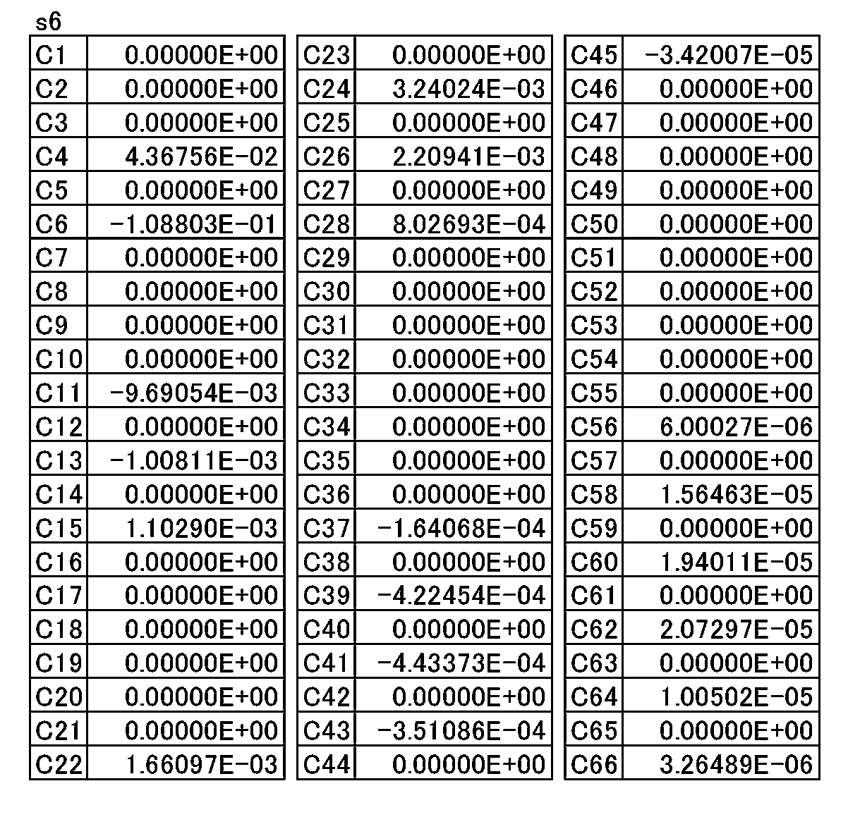

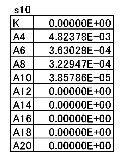

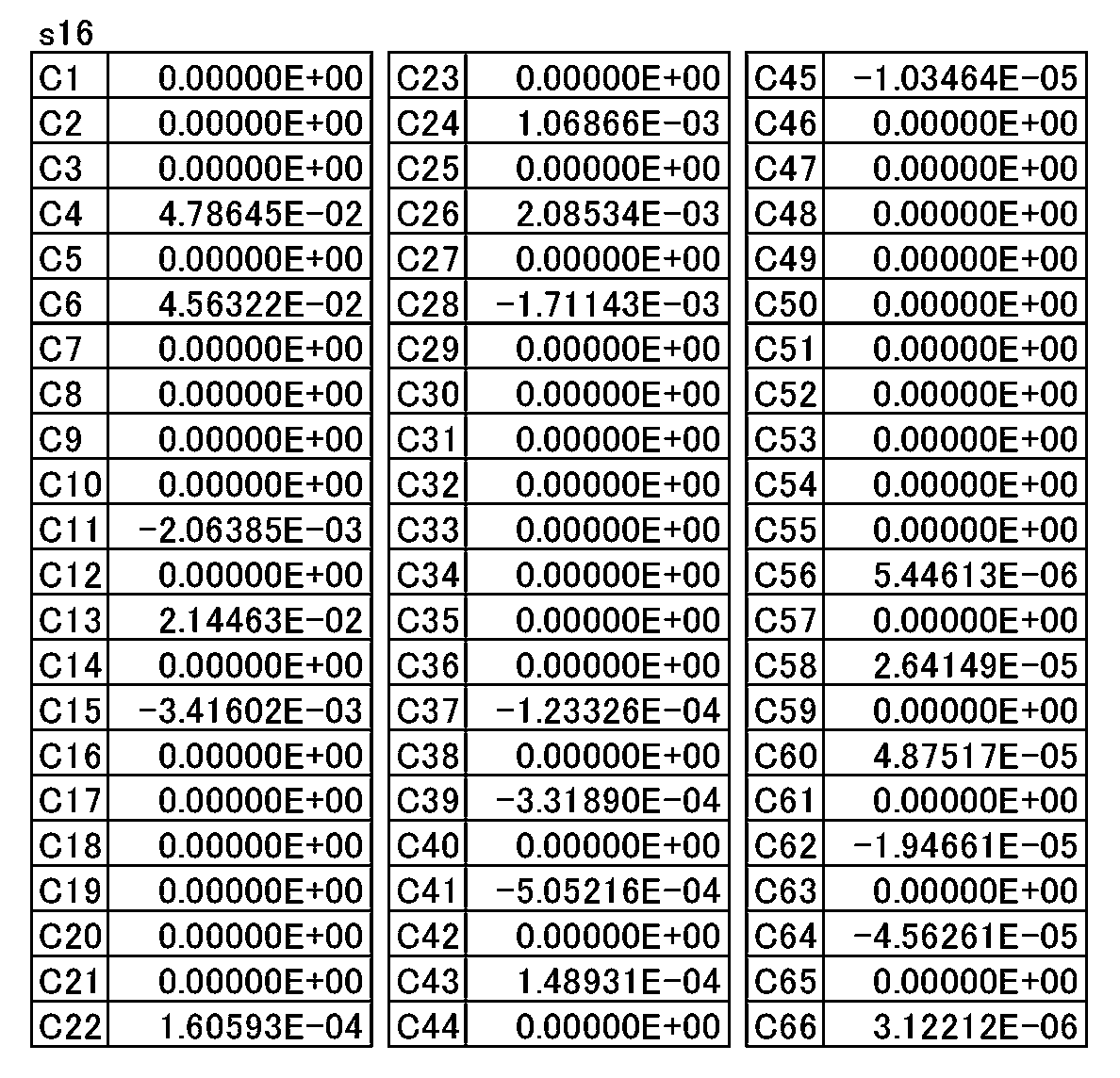
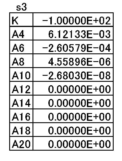
図14は、数値実施例3に係るレンズ系131の無限遠合焦状態の球面収差図及び非点収差図である。また、図15は、数値実施例3に係るレンズ系131の無限遠合焦状態の画角と像点の関係を示した図である。図15に示すレンズ系131の場合も、通常の回転対称レンズに比較して、像面の形状が拡大され、矩形の撮像素子102の感光面の領域を有効活用できていることが分かる。数値実施例3のレンズ系131は、図3に示した実施の形態3に対応する。数値実施例3のレンズ系131の面データを表17に、各種データを表18に、第3面、第4面、第5面、第6面、第7面、第10面、第12面、第13面および第14面の非球面・自由曲面データをそれぞれ表19、表20、表21、表22、表23、表24、表25、表26および表27に示す。





111,121,131 レンズ系
102 撮像素子
103 カメラ本体
200 撮像システム
201 撮像光学系
202 画像処理部
A 開口絞り
L1~L8 レンズ素子
Claims (21)
- 光軸に配置された矩形の撮像素子に結像するレンズ系であって、
前記光軸に対して非対称である第2自由曲面レンズを備え、
前記光軸から最短像高に対する所定の比率の長さ離れた円における前記第2自由曲面レンズのサグ量が、前記光軸を通り前記撮像素子の長辺に平行な第1面と前記円との交点、及び前記光軸を通り前記撮像素子の短辺に平行な第2面と前記円との交点以外に極値を有する、
レンズ系。 - 前記所定の比率は40%~80%である、
請求項1に記載のレンズ系。 - 物体側と像面側との間に開口絞りを有し、
前記開口絞りより物体側に第1自由曲面レンズを、前記開口絞りより像面側に前記第2自由曲面レンズを有する、
請求項1又は2に記載のレンズ系。 - 前記第2自由曲面レンズは最も像面側に配置され、物体側と像面側の両面が自由曲面である、
請求項3に記載のレンズ系。 - 物体側から順に、物体側に凸形状の負のパワーを有するメニスカスである第1レンズ素子と、負のパワーを有する第2レンズ素子を有する、
請求項1~4のいずれかに記載のレンズ系。 - 前記第1自由曲面レンズは前記第2レンズ素子の像面側に配置され、少なくとも物体側が自由曲面である、
請求項5に記載のレンズ系。 - 前記光軸に対して回転対称なレンズ素子を少なくとも3つ以上有する、
請求項1~6のいずれかに記載のレンズ系。 - 前記撮像素子の感光面と前記光軸との交点から前記感光面の角部への方向の±25°の範囲に前記極値を有する、
請求項1~7のいずれかに記載のレンズ系。 - 前記撮像素子の感光面の長辺と短辺の比がa対bであるとき、前記第1面に対してtan-1(b/a)±25°の範囲に前記極値を有する、
請求項1~7のいずれかに記載のレンズ系。 - 前記撮像素子の長辺と短辺の比が16対9であるとき、前記第1面に対して29±25°の範囲に前記極値を有する、
請求項1~7のいずれかに記載のレンズ系。 - 前記第1面に対して33±21°の範囲に前記極値を有する、
請求項1~7のいずれかに記載のレンズ系。 - 以下の条件(1)を満足する、請求項1に記載のレンズ系:
ωLONG>60° ・・・(1)
ここで、
ωLONG:撮像素子の長辺方向の最大半画角
である。 - 以下の条件(2)を満足する、請求項1に記載のレンズ系:
1<DLSHORT/DSSHORT ・・・(2)
ここで、
DLSHORT:撮像素子の短辺方向の最大半画角と等しい画角の、撮像素子の長辺方向の入射光に対する像点と、撮像素子に垂直な入射光に対する像点との長辺方向の最大距離
DSSHORT:撮像素子の短辺方向の最大半画角の入射光に対する像点と撮像素子に垂直な入射光に対する像点との短辺方向の最大距離
である。 - 以下の条件(3)を満足する、請求項1に記載のレンズ系:
0.5<DSSHORT×ωLONG/(DLLONG×ωSHORT)<1 ・・・(3)
ここで、
ωLONG:撮像素子の長辺方向の最大半画角
ωSHORT:撮像素子の短辺方向の最大半画角
DLLONG:撮像素子の長辺方向の最大半画角の入射光に対する像点と撮像素子に垂直な入射光に対する像点との長辺方向の最大距離
DSSHORT:撮像素子の短辺方向の最大半画角の入射光に対する像点と撮像素子に垂直な入射光に対する像点との短辺方向の最大距離
である。 - 以下の条件(4)を満足する、請求項1に記載のレンズ系:
ωLONG-ωSHORT>0 ・・・(4)
ここで、
ωLONG:撮像素子の長辺方向の最大半画角
ωSHORT:撮像素子の短辺方向の最大半画角
である。 - 以下の条件(5)を満足する、請求項1に記載のレンズ系:
L×Fno./DLLONG<40 ・・・(5)
ここで、
L:レンズ系の光学全長
Fno.:レンズ系のF値
DLLONG:撮像素子の長辺方向の最大半画角の入射光に対する像点と撮像素子に垂直な入射光に対する像点との長辺方向の最大距離
である。 - 以下の条件(6)を満足する、請求項1に記載のレンズ系:
nFREE<1.7 ・・・(6)
ここで、
nFREE:第1又は第2自由曲面レンズのd線に対する屈折率
である。 - レンズ素子と開口絞りとをさらに有し、以下の条件(7)を満足する、請求項1に記載のレンズ系:
-3≦No-Ni≦3 ・・・(7)
ここで、
No:開口絞りよりも物体側のレンズ素子の枚数
Ni:開口絞りよりも像面側のレンズ素子(第2自由曲面レンズを含む)の枚数
である。 - 前記レンズ系のイメージサークルが、前記撮像素子で包含されない、
請求項1に記載のレンズ系。 - 請求項1に記載のレンズ系と、
前記光軸で前記レンズ系が結像する位置に配置された矩形の前記撮像素子と、を備える、
カメラシステム。 - 請求項1に記載のレンズ系と、
前記光軸で前記レンズ系が結像する位置に配置された矩形の前記撮像素子と、
前記撮像素子が生成する画像を処理する画像処理部と、を備える、
撮像システム。
Priority Applications (4)
| Application Number | Priority Date | Filing Date | Title |
|---|---|---|---|
| EP18817976.6A EP3640699A4 (en) | 2017-06-13 | 2018-02-13 | LENS SYSTEM, CAMERA SYSTEM, AND IMAGING DEVICE |
| JP2019525066A JP7117605B2 (ja) | 2017-06-13 | 2018-02-13 | レンズ系、カメラシステム及び撮像システム |
| CN201880038308.1A CN110730922B (zh) | 2017-06-13 | 2018-02-13 | 透镜系统、摄像机系统以及摄像系统 |
| US16/709,644 US11493732B2 (en) | 2017-06-13 | 2019-12-10 | Lens system, camera system, and imaging system |
Applications Claiming Priority (2)
| Application Number | Priority Date | Filing Date | Title |
|---|---|---|---|
| JP2017-115546 | 2017-06-13 | ||
| JP2017115546 | 2017-06-13 |
Related Child Applications (1)
| Application Number | Title | Priority Date | Filing Date |
|---|---|---|---|
| US16/709,644 Continuation US11493732B2 (en) | 2017-06-13 | 2019-12-10 | Lens system, camera system, and imaging system |
Publications (1)
| Publication Number | Publication Date |
|---|---|
| WO2018230033A1 true WO2018230033A1 (ja) | 2018-12-20 |
Family
ID=64658647
Family Applications (1)
| Application Number | Title | Priority Date | Filing Date |
|---|---|---|---|
| PCT/JP2018/004774 Ceased WO2018230033A1 (ja) | 2017-06-13 | 2018-02-13 | レンズ系、カメラシステム及び撮像システム |
Country Status (5)
| Country | Link |
|---|---|
| US (1) | US11493732B2 (ja) |
| EP (1) | EP3640699A4 (ja) |
| JP (1) | JP7117605B2 (ja) |
| CN (1) | CN110730922B (ja) |
| WO (1) | WO2018230033A1 (ja) |
Cited By (8)
| Publication number | Priority date | Publication date | Assignee | Title |
|---|---|---|---|---|
| JPWO2021065091A1 (ja) * | 2019-09-30 | 2021-04-08 | ||
| JPWO2021065092A1 (ja) * | 2019-09-30 | 2021-04-08 | ||
| WO2021134286A1 (zh) * | 2019-12-30 | 2021-07-08 | 诚瑞光学(常州)股份有限公司 | 摄像光学镜头 |
| JP7007435B1 (ja) | 2020-07-02 | 2022-01-24 | エーエーシー オプティックス ソリューションズ ピーティーイー リミテッド | 撮像光学レンズ |
| JP7011691B1 (ja) | 2020-07-02 | 2022-01-27 | エーエーシー オプティックス ソリューションズ ピーティーイー リミテッド | 撮像光学レンズ |
| JP2022022935A (ja) * | 2020-07-02 | 2022-02-07 | エーエーシー オプティックス ソリューションズ ピーティーイー リミテッド | 撮像光学レンズ |
| JP2022023762A (ja) * | 2020-07-27 | 2022-02-08 | エーエーシー オプティクス (チャンジョウ)カンパニーリミテッド | 撮像光学レンズ |
| JP2022023758A (ja) * | 2020-07-27 | 2022-02-08 | ジョウシュウシ レイテック オプトロニクス カンパニーリミテッド | 撮像光学レンズ |
Families Citing this family (4)
| Publication number | Priority date | Publication date | Assignee | Title |
|---|---|---|---|---|
| JP6607426B2 (ja) * | 2017-06-13 | 2019-11-20 | パナソニックIpマネジメント株式会社 | レンズ系、カメラシステム及び撮像システム |
| EP3640698B1 (en) | 2017-06-13 | 2023-05-17 | Panasonic Intellectual Property Management Co., Ltd. | Lens system, camera system, and imaging system |
| CN109541783B (zh) * | 2019-01-07 | 2024-04-19 | 浙江舜宇光学有限公司 | 摄像镜头 |
| KR20240044749A (ko) * | 2022-09-29 | 2024-04-05 | 엘지이노텍 주식회사 | 광학계 및 이를 포함하는 카메라 장치 |
Citations (4)
| Publication number | Priority date | Publication date | Assignee | Title |
|---|---|---|---|---|
| WO2003101599A1 (en) | 2002-06-03 | 2003-12-11 | Cemvac System Ab | Feeding device for a monomer |
| JP2006011093A (ja) * | 2004-06-25 | 2006-01-12 | Konica Minolta Opto Inc | 超広角光学系、撮像装置、車載カメラ及びデジタル機器 |
| JP2010276755A (ja) * | 2009-05-27 | 2010-12-09 | Konica Minolta Opto Inc | 超広角アナモルフィックレンズ |
| JP2016148725A (ja) * | 2015-02-10 | 2016-08-18 | 株式会社トヨテック | 広角レンズ及び広角レンズユニット |
Family Cites Families (17)
| Publication number | Priority date | Publication date | Assignee | Title |
|---|---|---|---|---|
| JPS53127722A (en) * | 1977-04-13 | 1978-11-08 | Fuji Photo Film Co Ltd | Anamorphic lens |
| FR2827680B1 (fr) | 2001-07-20 | 2003-10-10 | Immervision Internat Pte Ltd | Procede de capture d'une image panoramique au moyen d'un capteur d'image de forme rectangulaire |
| DE10135658B4 (de) * | 2001-07-21 | 2005-03-17 | Stranz, Andreas H., Dipl.-Ing.(FH) | Verfahren und Vorrichtung zur Reinigung der Oberfläche eines Rotationskörpers |
| JP4738845B2 (ja) * | 2005-03-01 | 2011-08-03 | 株式会社オートネットワーク技術研究所 | 車両周辺監視装置 |
| JP5217146B2 (ja) * | 2006-10-13 | 2013-06-19 | 株式会社日立製作所 | 光学ユニット |
| KR101428136B1 (ko) * | 2007-08-03 | 2014-08-07 | 칼 짜이스 에스엠티 게엠베하 | 마이크로리소그래피용 투사 대물렌즈, 투사 노광 장치, 투사 노광 방법 및 광학 보정 플레이트 |
| KR100930167B1 (ko) * | 2007-09-19 | 2009-12-07 | 삼성전기주식회사 | 초광각 광학계 |
| JP2009109867A (ja) * | 2007-10-31 | 2009-05-21 | Hitachi Ltd | 映像投写装置 |
| JP4669539B2 (ja) * | 2008-10-01 | 2011-04-13 | 株式会社トプコン | 撮像装置、車載カメラ及び監視カメラ |
| JP6341442B2 (ja) * | 2014-01-28 | 2018-06-20 | 株式会社リコー | 画像読取用レンズ、画像読取装置および画像形成装置 |
| JP2016126254A (ja) | 2015-01-07 | 2016-07-11 | コニカミノルタ株式会社 | 撮像レンズ、撮像装置及び投影装置 |
| EP3640698B1 (en) * | 2017-06-13 | 2023-05-17 | Panasonic Intellectual Property Management Co., Ltd. | Lens system, camera system, and imaging system |
| JP6607426B2 (ja) * | 2017-06-13 | 2019-11-20 | パナソニックIpマネジメント株式会社 | レンズ系、カメラシステム及び撮像システム |
| JP7249599B2 (ja) * | 2018-03-28 | 2023-03-31 | パナソニックIpマネジメント株式会社 | レンズ系、撮像装置及び撮像システム |
| WO2020017200A1 (ja) * | 2018-07-18 | 2020-01-23 | パナソニックIpマネジメント株式会社 | 撮像光学系、撮像装置及び撮像システム |
| JP7228785B2 (ja) * | 2018-07-18 | 2023-02-27 | パナソニックIpマネジメント株式会社 | 撮像光学系、撮像装置及び撮像システム |
| JP6653456B1 (ja) * | 2019-05-24 | 2020-02-26 | パナソニックIpマネジメント株式会社 | 撮像装置 |
-
2018
- 2018-02-13 JP JP2019525066A patent/JP7117605B2/ja active Active
- 2018-02-13 EP EP18817976.6A patent/EP3640699A4/en not_active Withdrawn
- 2018-02-13 WO PCT/JP2018/004774 patent/WO2018230033A1/ja not_active Ceased
- 2018-02-13 CN CN201880038308.1A patent/CN110730922B/zh active Active
-
2019
- 2019-12-10 US US16/709,644 patent/US11493732B2/en active Active
Patent Citations (4)
| Publication number | Priority date | Publication date | Assignee | Title |
|---|---|---|---|---|
| WO2003101599A1 (en) | 2002-06-03 | 2003-12-11 | Cemvac System Ab | Feeding device for a monomer |
| JP2006011093A (ja) * | 2004-06-25 | 2006-01-12 | Konica Minolta Opto Inc | 超広角光学系、撮像装置、車載カメラ及びデジタル機器 |
| JP2010276755A (ja) * | 2009-05-27 | 2010-12-09 | Konica Minolta Opto Inc | 超広角アナモルフィックレンズ |
| JP2016148725A (ja) * | 2015-02-10 | 2016-08-18 | 株式会社トヨテック | 広角レンズ及び広角レンズユニット |
Non-Patent Citations (1)
| Title |
|---|
| See also references of EP3640699A4 |
Cited By (26)
| Publication number | Priority date | Publication date | Assignee | Title |
|---|---|---|---|---|
| EP4040209A4 (en) * | 2019-09-30 | 2022-12-07 | Panasonic Intellectual Property Management Co., Ltd. | Lens system, imaging device, and imaging system |
| EP4040210A4 (en) * | 2019-09-30 | 2022-12-07 | Panasonic Intellectual Property Management Co., Ltd. | LENS SYSTEM, IMAGING DEVICE AND IMAGING SYSTEM |
| WO2021065091A1 (ja) * | 2019-09-30 | 2021-04-08 | パナソニックIpマネジメント株式会社 | レンズ系、撮像装置及び撮像システム |
| WO2021065092A1 (ja) * | 2019-09-30 | 2021-04-08 | パナソニックIpマネジメント株式会社 | レンズ系、撮像装置及び撮像システム |
| US12352933B2 (en) | 2019-09-30 | 2025-07-08 | Panasonic Intellectual Property Management Co., Ltd. | Lens system, imaging device, and imaging system |
| US12287462B2 (en) | 2019-09-30 | 2025-04-29 | Panasonic Intellectual Property Management Co., Ltd. | Lens system, imaging device, and imaging system |
| CN114503005B (zh) * | 2019-09-30 | 2024-06-14 | 松下知识产权经营株式会社 | 透镜系统、摄像装置以及摄像系统 |
| CN114503005A (zh) * | 2019-09-30 | 2022-05-13 | 松下知识产权经营株式会社 | 透镜系统、摄像装置以及摄像系统 |
| JP7442074B2 (ja) | 2019-09-30 | 2024-03-04 | パナソニックIpマネジメント株式会社 | レンズ系、撮像装置及び撮像システム |
| JP7442073B2 (ja) | 2019-09-30 | 2024-03-04 | パナソニックIpマネジメント株式会社 | レンズ系、撮像装置及び撮像システム |
| CN114450615A (zh) * | 2019-09-30 | 2022-05-06 | 松下知识产权经营株式会社 | 透镜系统、摄像装置以及摄像系统 |
| US20220221694A1 (en) * | 2019-09-30 | 2022-07-14 | Panasonic Intellectual Property Management Co., Ltd. | Lens system, imaging device, and imaging system |
| JPWO2021065092A1 (ja) * | 2019-09-30 | 2021-04-08 | ||
| CN114450615B (zh) * | 2019-09-30 | 2024-04-12 | 松下知识产权经营株式会社 | 透镜系统、摄像装置以及摄像系统 |
| JPWO2021065091A1 (ja) * | 2019-09-30 | 2021-04-08 | ||
| WO2021134286A1 (zh) * | 2019-12-30 | 2021-07-08 | 诚瑞光学(常州)股份有限公司 | 摄像光学镜头 |
| JP7079296B2 (ja) | 2020-07-02 | 2022-06-01 | エーエーシー オプティックス ソリューションズ ピーティーイー リミテッド | 撮像光学レンズ |
| JP2022022937A (ja) * | 2020-07-02 | 2022-02-07 | エーエーシー オプティックス ソリューションズ ピーティーイー リミテッド | 撮像光学レンズ |
| JP2022022936A (ja) * | 2020-07-02 | 2022-02-07 | エーエーシー オプティックス ソリューションズ ピーティーイー リミテッド | 撮像光学レンズ |
| JP2022022935A (ja) * | 2020-07-02 | 2022-02-07 | エーエーシー オプティックス ソリューションズ ピーティーイー リミテッド | 撮像光学レンズ |
| JP7011691B1 (ja) | 2020-07-02 | 2022-01-27 | エーエーシー オプティックス ソリューションズ ピーティーイー リミテッド | 撮像光学レンズ |
| JP7007435B1 (ja) | 2020-07-02 | 2022-01-24 | エーエーシー オプティックス ソリューションズ ピーティーイー リミテッド | 撮像光学レンズ |
| JP7082181B2 (ja) | 2020-07-27 | 2022-06-07 | エーエーシー オプティクス (チャンジョウ)カンパニーリミテッド | 撮像光学レンズ |
| JP2022023758A (ja) * | 2020-07-27 | 2022-02-08 | ジョウシュウシ レイテック オプトロニクス カンパニーリミテッド | 撮像光学レンズ |
| JP7072630B2 (ja) | 2020-07-27 | 2022-05-20 | ジョウシュウシ レイテック オプトロニクス カンパニーリミテッド | 撮像光学レンズ |
| JP2022023762A (ja) * | 2020-07-27 | 2022-02-08 | エーエーシー オプティクス (チャンジョウ)カンパニーリミテッド | 撮像光学レンズ |
Also Published As
| Publication number | Publication date |
|---|---|
| US20200110245A1 (en) | 2020-04-09 |
| JP7117605B2 (ja) | 2022-08-15 |
| CN110730922A (zh) | 2020-01-24 |
| JPWO2018230033A1 (ja) | 2020-04-23 |
| US11493732B2 (en) | 2022-11-08 |
| EP3640699A4 (en) | 2020-06-10 |
| CN110730922B (zh) | 2021-10-26 |
| EP3640699A1 (en) | 2020-04-22 |
Similar Documents
| Publication | Publication Date | Title |
|---|---|---|
| JP7117605B2 (ja) | レンズ系、カメラシステム及び撮像システム | |
| JP6607426B2 (ja) | レンズ系、カメラシステム及び撮像システム | |
| CN114563863B (zh) | 光学成像系统 | |
| JP7108935B2 (ja) | レンズ系、カメラシステム及び撮像システム | |
| CN110208932B (zh) | 光学系统和成像装置 | |
| JP4613111B2 (ja) | 光学装置 | |
| JP5252842B2 (ja) | 撮像レンズ | |
| JP5096226B2 (ja) | 広角レンズ | |
| CN105652409A (zh) | 光学成像系统 | |
| JP2009128654A (ja) | 魚眼系撮像レンズ | |
| JP2003322792A (ja) | 撮像レンズ | |
| CN115145010A (zh) | 摄像光学系统 | |
| CN105759395A (zh) | 光学成像系统 | |
| CN105700116A (zh) | 光学成像系统 | |
| JP2008281859A (ja) | 広角レンズ | |
| JP6827173B2 (ja) | レンズ系および該レンズ系を含むカメラシステム | |
| CN105759400A (zh) | 光学成像系统 | |
| WO2016047112A1 (ja) | レンズ系、及び撮像装置 | |
| CN105759398A (zh) | 光学成像系统 | |
| JPWO2018163831A1 (ja) | レンズ系、交換レンズ装置及びカメラシステム | |
| CN105759401A (zh) | 光学成像系统 | |
| CN102540425A (zh) | 摄像透镜 | |
| CN105759397A (zh) | 光学成像系统 | |
| JP4932508B2 (ja) | 広角レンズ系 | |
| JP2020122824A (ja) | 撮像レンズ及び撮像装置 |
Legal Events
| Date | Code | Title | Description |
|---|---|---|---|
| 121 | Ep: the epo has been informed by wipo that ep was designated in this application |
Ref document number: 18817976 Country of ref document: EP Kind code of ref document: A1 |
|
| ENP | Entry into the national phase |
Ref document number: 2019525066 Country of ref document: JP Kind code of ref document: A |
|
| NENP | Non-entry into the national phase |
Ref country code: DE |
|
| ENP | Entry into the national phase |
Ref document number: 2018817976 Country of ref document: EP Effective date: 20200113 |
|
| WWW | Wipo information: withdrawn in national office |
Ref document number: 2018817976 Country of ref document: EP |