WO2018230040A1 - 光コネクタの清掃工具 - Google Patents
光コネクタの清掃工具 Download PDFInfo
- Publication number
- WO2018230040A1 WO2018230040A1 PCT/JP2018/005470 JP2018005470W WO2018230040A1 WO 2018230040 A1 WO2018230040 A1 WO 2018230040A1 JP 2018005470 W JP2018005470 W JP 2018005470W WO 2018230040 A1 WO2018230040 A1 WO 2018230040A1
- Authority
- WO
- WIPO (PCT)
- Prior art keywords
- head
- optical connector
- housing
- cleaning tool
- unit
- Prior art date
- Legal status (The legal status is an assumption and is not a legal conclusion. Google has not performed a legal analysis and makes no representation as to the accuracy of the status listed.)
- Ceased
Links
Images


Classifications
-
- G—PHYSICS
- G02—OPTICS
- G02B—OPTICAL ELEMENTS, SYSTEMS OR APPARATUS
- G02B6/00—Light guides; Structural details of arrangements comprising light guides and other optical elements, e.g. couplings
- G02B6/24—Coupling light guides
- G02B6/36—Mechanical coupling means
- G02B6/38—Mechanical coupling means having fibre to fibre mating means
- G02B6/3807—Dismountable connectors, i.e. comprising plugs
- G02B6/3833—Details of mounting fibres in ferrules; Assembly methods; Manufacture
- G02B6/3866—Devices, tools or methods for cleaning connectors
Definitions
- the present invention relates to an optical connector cleaning tool.
- a cleaning tool for cleaning the connection end face of the optical connector (the end face of the ferrule) is known.
- the optical connector to be cleaned in which the cleaning tool is used includes an optical connector (backplane connector) attached to a backplane board located in the back of the plug-in unit.
- Patent Document 1 discloses that an optical connector end surface cleaning tool is inserted and connected to a connector hole of the printboard side housing, and the printboard side housing is connected to the backplane side housing.
- An optical connector cleaning tool that can clean the connection end face of the optical connector by fitting the connector to the optical connector is described (see, for example, FIG. 7 of Patent Document 1).
- Patent Document 2 describes that a board to which a cleaning tool including a cleaning tape (cleaning body) wound around a pressing surface of a head is attached is slid into a guide groove (for example, Patent Document 2). (See FIG. 9).
- the backplane side housing in order to absorb the relative displacement between the backplane side housing and the printed board side housing when the optical connector is connected, the backplane side housing is the backplane board.
- a so-called floating mechanism that can move is provided.
- the cleaning tool housing and the backplane connector housing cannot be easily fitted by simply sliding the cleaning tool fixed to the board along the guide groove. was there.
- the cleaning body of the cleaning tool cannot be properly pressed against the connection end surface of the backplane connector because the housing is not properly fitted to the backplane connector housing. Further, such a problem may occur in the same manner even when the connection end face is cleaned by fitting into a housing of an optical connector other than the backplane connector (for example, an MPO type optical connector).
- An object of the present invention is to provide an optical connector cleaning tool that can be easily fitted into a housing of an optical connector to be cleaned.
- optical connector cleaning tools which include a main body, a substrate to which the main body is fixed, a head that presses a cleaning body against the optical connector, and the head.
- a head unit including a head housing, wherein the head housing is formed so as to be fitted to a housing of the optical connector, and the head unit is provided to be movable with respect to the substrate. It is the cleaning tool of the optical connector characterized by the above-mentioned.
- the cleaning tool can be easily fitted into the housing of the optical connector to be cleaned.
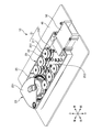
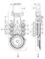
- FIG. 1 is a perspective view of the cleaning tool 10 of the present embodiment.
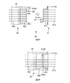
- 2A and 2B are explanatory diagrams of the configuration of the backplane connector 90.
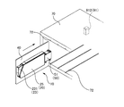
- FIG. FIG. 3 is an explanatory diagram at the time of cleaning by the cleaning tool 10 of the present embodiment.
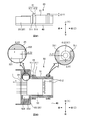
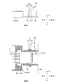
- FIG. 4A is a side view of an enlarged part of the head unit 50 of the cleaning tool 10.
- FIG. 4B is a cross-sectional view of an enlarged part of the head unit 50 of the cleaning tool 10.
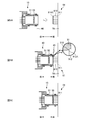
- 5A to 5C are explanatory views showing a state in which the head housing 51 of the head unit 50 and the backplane housing 912 of the backplane side optical connector 91 are fitted.
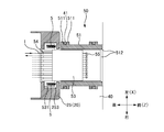
- FIG. 6A is a side view of an enlarged part of a modified example of the head unit 50.
- FIG. 6B is a cross-sectional view of an enlarged portion of a modification of the head unit 50.
- FIG. 7 is a cross-sectional view of an enlarged portion of the head unit 50 to which the fixing member 5 is attached.
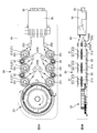
- 8A and 8B are explanatory views showing the inside of the main body 20 of the cleaning tool 10.
- FIG. 9A is a perspective view of the reel unit 21 of the main body 20.
- FIG. 9B is a perspective view of the drive unit 23 of the main body 20.
- FIG. 10A is an explanatory diagram showing the state of the reel unit 21 and the connecting portion 22 when the drive unit 233 of the drive unit 23 rotates forward.
- 10B is an explanatory diagram showing a state of the reel unit 21 and the connecting portion 22 when the drive unit 233 of the drive unit 23 is reversed.
- 11A and 11B are explanatory diagrams illustrating an example of the main body 20 that does not have the connecting portion 22.
- An optical connector cleaning tool comprising: a main unit; a substrate to which the main unit is fixed; a head that presses a cleaning body against the optical connector; and a head unit that includes a head housing that houses the head.
- the head housing is formed so as to be fitted with the housing of the optical connector, and the head unit is provided to be movable with respect to the substrate.
- the cleaning tool becomes clear. According to such a cleaning tool for an optical connector, the cleaning tool can be easily fitted to the housing of the optical connector to be cleaned.
- the stopper mechanism includes a pile member provided on the substrate and a pile receiving portion provided on the head housing and provided with a gap between the pile member.
- the stopper mechanism can suppress that a head unit remove
- the direction in which the head unit moves relative to the substrate is preferably perpendicular to the direction in which the head presses the cleaning body against the optical connector. Therefore, the cleaning tool can be easily fitted to the housing of the optical connector to be cleaned.
- the head unit is preferably provided so as to be movable with respect to the main body. Thereby, the cleaning tool can be easily fitted to the housing of the optical connector to be cleaned.
- the head unit further includes a fixing member that restricts movement of the head unit relative to the substrate.
- a fixing member that restricts movement of the head unit relative to the substrate.
- the main body includes a supply reel that supplies the cleaning body to the head, a take-up reel that winds up the cleaning body collected from the head, and the supply reel and the take-up reel that are rotatable.
- a plurality of reel units including a rotation shaft, and a drive unit that drives a rotational force with respect to the plurality of reel units, wherein the drive unit supplies the cleaning body to the head or from the head. It is desirable to provide a reverse rotation prevention mechanism that restricts rotation in only one direction in which the collected cleaning body is wound up. Thereby, since it is sufficient to provide the reverse rotation prevention mechanism only in the drive unit, the number of parts of the cleaning tool can be reduced.
- the main body has a connecting portion that transmits a driving force between the plurality of reel units. Thereby, the driving force of the drive unit can be transmitted to the plurality of reel units.
- FIG. 1 is a perspective view of the cleaning tool 10 of the present embodiment.
- the cleaning tool 10 in a state where the cover portion of the main body housing 25 is removed is shown in order to show the inside of the main body portion 20 of the cleaning tool 10.
- each direction is defined as shown in FIG. That is, the direction in which the cleaning tool 10 and the optical connector to be cleaned (not shown in FIG. 1; see FIGS. 2A to 3 (backplane side optical connector 91) described later) are approached and separated is referred to as the “front-rear direction”.
- the backplane side optical connector 91 side as viewed from the cleaning tool 10 is referred to as “front”, and the opposite side is referred to as “rear”.
- the axial direction of the rotation shaft 251 of the supply reel 211 and the take-up reel 212 is “up-down direction”, the side of the main body 20 viewed from the substrate 40 is “up”, and the opposite side is “down”.
- the direction perpendicular to the front-rear direction and the up-down direction is referred to as “left-right direction”, the right side when viewing the front side from the rear side is “right”, and the left side is “left”.
- the left-right direction, the up-down direction, and the front-rear direction may be referred to as “X direction”, “Y direction”, and “Z direction”, respectively, in this order.
- the cleaning tool 10 is a tool used for cleaning the optical connector.
- the optical connector to be cleaned by the cleaning tool 10 of the present embodiment is an optical connector (backplane connector) attached to a connector attachment wall (middle plane or backplane board) located in the back of the plug-in unit.
- backplane connector used as cleaning object
- the structure of the cleaning tool 10 of this embodiment is demonstrated after that.
- FIG. 1A and 2B are explanatory diagrams of the configuration of the backplane connector 90.
- FIG. The backplane connector 90 includes a backplane side optical connector 91 and a print board side optical connector 92.
- the backplane side optical connector 91 is an optical connector provided on the backplane board 71 side of the plug-in unit 70. As shown in FIG.
- the backplane side optical connector 91 includes a plurality of optical connectors 911 and a backplane housing 912 that houses the plurality of optical connectors 911.
- a plurality of optical connectors 911 are provided at the ends of the optical fibers 913.
- the printed board side optical connector 92 is an optical connector provided on the printed board 80 side.
- the print board side optical connector 92 includes a plurality of optical connectors 921 and a print board housing 922.
- a plurality of optical connectors 921 are provided at the ends of the optical fibers 923, respectively.
- the backplane connector 90 is a plug-in type optical connector that constitutes an optical connector adapter that connects a plurality of optical connectors 911 on the backplane side and a plurality of optical connectors 921 on the printed board side. As shown in FIG. 2B, the backplane connector 90 is configured by fitting a printboard housing 922 attached to the printboard 80 to a backplane housing 912 attached to the backplane board 71 of the plug-in unit 70. The plurality of optical connectors 911 and the plurality of optical connectors 921 are respectively optically connected.
- the optical connector 911 provided at the end of the optical fiber 913 is a connection component for optically connecting the optical fiber 913 and the optical fiber 923 via the optical connector 921.
- the optical connector 911 includes a ferrule 914 and an optical connector housing (not shown).
- the ferrule 914 is a member that holds the end of the optical fiber 913.
- a ferrule end surface 914A of the ferrule 914 is a connection end surface of the optical connector 911. That is, the ferrule end surface 914 ⁇ / b> A is a connection end surface of the backplane side optical connector 91.
- the optical connector 921 provided at the end of the optical fiber 923 is a connection component for optically connecting the optical fiber 923 and the optical fiber 913 via the optical connector 911.
- the optical connector 921 includes a ferrule 924 and an optical connector housing (not shown).
- the ferrule 924 is a member that holds the end of the optical fiber 923.
- a ferrule end surface 924A of the ferrule 924 is a connection end surface of the optical connector 921. That is, the ferrule end surface 924 ⁇ / b> A of the ferrule 924 is a connection end surface of the printed board side optical connector 92.
- the operator slides the print board 80 toward the back plane board 71 and moves it (see the arrow in FIG. 2A), and fits the print board housing 922 to the back plane housing 912.
- the ferrule 914 of the optical connector 911 and the ferrule 924 of the optical connector 921 are brought into contact with each other, and the plurality of optical connectors 911 and the plurality of optical connectors 921 are optically connected. That is, the optical fibers 913 of the plurality of optical connectors 911 and the optical fibers 923 of the plurality of optical connectors 921 are optically connected.
- FIG. 3 is an explanatory diagram at the time of cleaning by the cleaning tool 10 of the present embodiment.
- the optical connector 921 is provided on the printed board 80 side. Then, by fitting the print board housing 922 attached to the print board 80 into the back plane housing 912 attached to the back plane board 71 of the plug-in unit 70, the plurality of optical connectors 911 and the plurality of optical connectors 921 are made. It was optically connected.
- a cleaning tool (a tape-shaped cleaning body wound around the pressing surface of the head) is attached to the substrate instead of the printed board 80. Then, by fitting the housing in which the cleaning tool is accommodated into the backplane housing, the cleaning body is pressed against the connection end surfaces of the plurality of optical connectors on the backplane side and cleaned.
- the operator slides the substrate 40 of the cleaning tool 10 along the guide groove 72 of the plug-in unit 70 and moves it.
- the head housing 51 of the head unit 50 is fitted into the backplane housing 912 of the backplane side optical connector 91.
- the cleaning body 1 wound around the pressing surface of the head 55 accommodated in the head unit 50 of the cleaning tool 10 (not shown in FIG. 3, see FIG. 4B described later) is used as the optical connector of the backplane side optical connector 91. 911 (not shown in FIG. 3, see FIGS. 2A and 2B).
- the cleaning tool 10 includes a main body 20, a substrate 40, and a head unit 50 (see FIGS. 1 and 3).
- the main body 20 is a member that houses a member (for example, a reel unit 21 described later) for supplying and collecting the cleaning body 1 to the head unit 50.
- the main body 20 is also a member that houses a member (a driving unit 23 described later) that drives the reel unit 21 and the like.
- members (reel unit 21 and the like) for supplying and collecting the cleaning body 1 to the head unit 50 are accommodated in the main body housing 25 of the main body portion 20.
- most of the members (drive unit 23) for driving the reel unit 21 and the like are accommodated inside the main body housing 25, but a part (a part of the drive lever 231) is exposed from the main body housing 25. (See FIG. 3).
- the main body 20 is fixed to a substrate 40 described later. The detailed configuration and operation of the main body 20 will be described later.
- the substrate 40 is a member that holds the main body 20 and is guided by the guide groove 72 of the plug-in unit 70 when the cleaning tool 10 is slid on the plug-in unit 70.
- the substrate 40 may be formed in the same shape as the printed board 80. As a result, the substrate 40 can be inserted into the guide groove 72 of the plug-in unit 70.
- the head unit 50 is a member that fits with the backplane housing 912 of the backplane side optical connector 91 while accommodating the head 55 around which the cleaning body 1 is wound around the pressing surface. The detailed configuration of the head unit 50 will be described later.
- ⁇ Floating mechanism> In the backplane connector 90 described with reference to FIGS. 2A and 2B, a plurality of printboard housings 922 attached to the printboard 80 are fitted into backplane housings 912 attached to the backplane board 71 of the plug-in unit 70.
- the optical connector 911 and the plurality of optical connectors 921 are optically connected.
- a floating mechanism is provided in the back plane connector 90 in order to absorb the relative displacement between the print board housing 922 and the back plane housing 912. May have. In such a floating mechanism, the backplane housing 912 is movable with respect to the backplane board 71 (see the arrow in FIG. 2A).
- the print board housing 922 is also movable with respect to the print board 80 (see the arrow in FIG. 2A). As a result, even if a relative positional shift occurs when the print board housing 922 and the backplane housing 912 are fitted, for example, the print board housing 922 moves relative to the print board 80, so that these relative Misalignment can be absorbed.
- the cleaning tool 10 of the present embodiment is provided with a floating mechanism that allows the head unit 50 to move relative to the substrate 40. Below, while explaining the detailed structure of the head unit 50, the floating mechanism of the cleaning tool 10 is demonstrated.
- FIG. 4A is a side view of an enlarged part of the head unit 50 of the cleaning tool 10.
- FIG. 4B is a cross-sectional view of an enlarged part of the head unit 50 of the cleaning tool 10.
- FIG. 4B in order to explain the vicinity of the pile member 41 in detail, the figure which expanded further the vicinity of the pile member 41 is shown on the upper right.
- FIG. 4B in order to explain the vicinity of the flange portion 531 in detail, an enlarged view of the vicinity of the flange portion 531 is shown in the upper left. 4B shows a cross section in which only the main body housing 25 and the head housing 51 are cut by a plane perpendicular to the vertical direction in order to explain the floating mechanism.
- the head unit 50 includes a head 55, a head support portion 53, and a head housing 51. Further, a pile member 41 is provided on the substrate 40.
- the head 55 is a member for pressing the cleaning body 1 against a connection end surface (ferrule end surface 914A) of an optical connector (backplane side optical connector 91, a plurality of optical connectors 911) to be cleaned by the cleaning tool 10.
- the front end surface of the head 55 is a pressing surface for pressing the cleaning body 1 against the ferrule end surface 914A.
- the cleaning body 1 is wound around the pressing surface (front end surface of the head 55), the unused cleaning body 1 is supplied from the upstream side of the pressing surface, and the used cleaning body 1 is downstream of the pressing surface. (See the arrow in FIG. 4B).
- a plurality (six in this case) of ferrule end surfaces 914A are arranged on the backplane side optical connector 91, and the head unit 50 has a plurality (here, a plurality of ferrule end surfaces 914A corresponding to the plurality of ferrule end surfaces 914A). 6) heads 55 are provided. Then, the cleaning body 1 is supplied and collected for each head 55.
- the unused cleaning body 1 is supplied from the upstream side of the pressing surface, or the used cleaning body 1 is sent to the downstream side of the pressing surface. 1 may be referred to as “transport”. Further, the direction in which the cleaning body 1 is transported may be referred to as a “transport direction”.
- the head support portion 53 is a member that regulates the front drop of the head 55 and supports the plurality of heads 55.
- the head support portion 53 is accommodated in a head housing 51 described later. Further, the head support portion 53 is fixed to the head housing 51.
- a guide 54 is provided on the rear side of the head support 53.
- the guide part 54 is a part for guiding the cleaning body 1 in the transport direction while restricting movement of the cleaning body 1 in a direction other than the transport direction during transport of the cleaning tool 10.
- a groove (not shown) may be formed along the conveyance direction of the cleaning body 1 on the guide surface of the guide section 54 (the surface on which the cleaning body 1 contacts the guide section 54). By transporting the cleaning body 1 in this groove, the movement range in a direction other than the transport direction of the cleaning body 1 is limited.
- a spring (not shown) is disposed between the guide portion 54 and the head 55, and the head 55 is pressed forward by this spring.
- the head support part 53 supports the head 55 so as to be able to move backward while restricting the front drop of the head 55.
- the head housing 51 is a member that accommodates the head 55 and the head support portion 53 and fits with the backplane housing 912 of the backplane-side optical connector 91.
- the head housing 51 is a cylindrical member extending in the front-rear direction, and houses the head 55 and the head support portion 53 inside the cylindrical shape.
- the head housing 51 may be formed in the same shape as the print board housing 922 of the print board side optical connector 92. Thus, the backplane housing 912 of the backplane side optical connector 91 can be fitted.
- the head housing 51 is provided with a pile receiving portion 511.
- the pile receiving portion 511 is a convex portion provided on the outer peripheral portion of the head housing 51 so as to extend in the vertical direction.
- the pile receiving part 511 is provided with a pair of convex portions in the front-rear direction.
- the pile receiving part 511 is provided so that the pile member 41 provided in the board
- a plurality of (here, four) pile members 41 are provided on the substrate 40, and the head housing 51 includes a plurality (here, four sets) of pile receiving portions 511 respectively corresponding to the plurality of pile members 41. ing.
- the pile member 41 is a rod-like member extending in the vertical direction.
- the pile member 41 is provided between the pile receiving portions 511 (a pair of convex portions).
- the lower end of the pile member 41 (the end opposite to the head 411 side described later) is fixed to the substrate 40. Therefore, the pile member 41 is a member that extends upward from the upper surface (a surface perpendicular to the vertical direction) of the substrate 40.
- a plurality of (here, four) pile members 41 are provided on the substrate 40. In this embodiment, the pile member 41 and the pile receiving part 511 are not mutually fixed.
- the pile member 41 includes a head 411 and a body 412.
- the head 411 is an upper part of the pile member 41.
- the head portion 411 is provided so as to protrude above the upper surface of the pile receiving portion 511. Further, the diameter of the head 411 (the size in the direction perpendicular to the vertical direction) is formed to be larger than the size between the pile receiving portions 511 (a pair of convex portions).
- the trunk portion 412 is a bar-like portion below the head portion 411. As shown in FIG. 4A, a part of the upper side of the pile member 41 protrudes upward from the upper surface of the pile receiving part 511, and the other part is between the pile receiving parts 511 (a pair of convex parts). Is provided.
- the pile member 41 and the pile receiving portion 511 are not fixed to each other. Therefore, in this embodiment, the board
- the head unit 50 is provided so as to be movable in the X direction and the Z direction with respect to the substrate 40.
- the lower surface of the head 411 of the pile member 41 and the upper surface of the head housing 51 are provided with a gap of ⁇ Y1. That is, the head unit 50 is provided so as to be movable in the Y direction with respect to the substrate 40.
- the pile member 41 and the pile receiving portion 511 constitute a floating mechanism for the substrate 40 of the head unit 50. That is, the head unit 50 is provided so as to be movable in three dimensions (XYZ directions) with respect to the substrate 40.
- the moving direction of the head unit 50 with respect to the substrate 40 may be only two directions (for example, only the X direction and the Y direction) or only one direction (for example, only the X direction).
- the relative displacement in the Z direction is absorbed by the spring provided between the guide portion 54 and the head 55 described above. can do. That is, since the plurality of heads 55 of the head unit 50 are supported by the spring provided in the head support portion 53 so as to be retractable, the Z-direction when the head housing 51 and the backplane housing 912 are fitted together is supported. Relative displacement can be absorbed. However, the relative positional shift amount in the Z direction between the head housing 51 and the backplane housing 912 may be different for each fitting.
- the pushback amount of the spring is fitted according to the amount of absorbing the relative displacement. It will be different from time to time. If it does so, the pressing force which presses the cleaning body 1 to the connection end surface (ferrule end surface 914A) of the backplane side optical connector 91 will each differ at the time of a fitting. For this reason, the direction in which the head unit 50 moves with respect to the substrate 40 is provided so as to be movable in the Z direction as well as only in the X direction and the Y direction, so that the amount of pushback of the spring is kept constant. The pressing force of the cleaning body 1 can be kept constant.
- the head unit 50 is not only provided so as to be movable with respect to the substrate 40, but the moving range is limited to a certain range.
- the pile member 41 (substrate 40) also constitutes a stopper mechanism that limits the movement range of the head housing 51 (head unit 50) including the pile receiving portion 511.
- the movement range in the X direction and the Z direction is defined by the size of the gap between the trunk portion 412 of the pile member 41 and the pair of convex portions of the pile receiving portion 511.
- the moving range in the Y direction is defined by the size of the gap between the lower surface of the head 411 of the pile member 41 and the upper surface of the head housing 51.
- the pile member 41 and the pile receiving portion 511 are not limited as long as the movement range of the head unit 50 relative to the substrate 40 is limited. According to such a stopper mechanism, the head unit 50 can be prevented from being detached from the substrate 40.
- the head unit 50 is provided so as to be movable with respect to the substrate 40.
- the head unit 50 may be provided so as to be movable with respect to the main body 20.
- the head support portion 53 is provided with a flange portion 531.
- the flange portion 531 is a portion protruding from the head support portion 53 on the left and right sides of the head support portion 53.
- the main body housing 25 of the main body portion 20 is provided with a recess 253 that accommodates the flange portion 531.
- a constant gap is provided between the flange portion 531 and the recess 253 by ⁇ X2 and ⁇ Z2.
- the head support portion 53 (head unit 50) is provided to be movable within a certain range in the X direction and the Z direction with respect to the main body housing 20 (main body portion 20).
- a certain gap (not shown) may be provided between the flange portion 531 and the recessed portion 253 by ⁇ Y2. That is, the head support portion 53 (head unit 50) is provided so as to be movable within a certain range in the Y direction with respect to the main body housing 20 (main body portion 20). Therefore, the head unit 50 is provided so as to be movable in three dimensions (XYZ directions) with respect to the main body 20.
- the gaps ( ⁇ X2, ⁇ Y2, ⁇ Z2) between the flange portion 531 and the concave portion 253 are based on the movement ranges ( ⁇ X1, ⁇ Y1, and ⁇ Z1) between the above-described pile member 41 (substrate 40) and the pile receiving portion 511 (head unit 50).
- the head unit 50 is provided so as to be movable with respect to the substrate 40 and the head unit 50 is provided so as to be movable with respect to the main body 20.
- FIGS. 5A to 5C are explanatory views showing how the head housing 51 of the head unit 50 and the backplane housing 912 of the backplane-side optical connector 91 are fitted together.
- the operation of the floating mechanism when the head housing 51 of the head unit 50 and the backplane housing 912 of the backplane side optical connector 91 are fitted together will be described.
- FIG. 5A shows a state before the head housing 51 and the backplane housing 912 are fitted together.
- the operator inserts the substrate 40 of the cleaning tool 10 into the guide groove of the plug-in unit 70 in order to fit the head housing 51 of the head unit 50 into the backplane housing 912 of the backplane-side optical connector 91. It is slid along 72 and moved (see the arrow in FIG. 5A).
- FIG. 5B shows a state when the head housing 51 and the backplane housing 912 start to be fitted.
- the substrate 40 is slid along the guide groove 72 of the plug-in unit 70, and the edge of the front surface of the head housing 51 (backplane housing 912 side) is the rear surface of the backplane housing 912 (head housing 51 side).
- This is the state when it comes into contact with the edge of the surface.
- the head housing 51 head unit 50
- These relative positional shifts can be absorbed by moving relative to each other. That is, the cleaning tool 10 can be easily fitted to the backplane side optical connector 91 to be cleaned. Further, the head housing 51 and the backplane housing 912 are aligned at the time of fitting.
- a taper portion 912A may be formed at the edge of the rear surface of the backplane housing 912 (the surface on the head housing 51 side).
- a tapered portion 512 is also formed on the front surface of the head housing 51 (on the backplane housing 912 side) so as to contact the tapered portion 912A.
- 4B shows a state where the taper portion 512 of the head housing 51 is in contact with the taper portion 912A of the backplane housing 912.
- FIG. When the substrate 40 is further slid along the guide groove 72 from this state (the cleaning tool 10 is moved to the backplane side optical connector 91 side), the tapered surfaces (tapered portion 512 and tapered portion 912A) slide. Can be moved.
- the head housing 51 (head unit 50) is movable with respect to the substrate 40, the head housing 51 (head unit) from the state in which the upper left portion of FIG. 50) moves upward with respect to the substrate 40, so that the head housing 51 (head unit 50) can be fitted to the backplane housing 912.
- FIG. 5C shows a state in which the fitting between the head housing 51 and the backplane housing 912 is completed and the cleaning body 1 is pressed against the ferrule end surfaces 914A of the plurality of optical connectors 911 of the backplane side optical connector 91. Further, when the cleaning body 1 is pressed against the ferrule end surface 914A, the head housing 51 and the backplane housing 912 are aligned in the front-rear direction. By driving the drive unit 23 in this state, the cleaning body 1 is conveyed and the ferrule end surface 914A is cleaned.
- the cleaning body 1 of the cleaning tool 10 can be appropriately pressed against the ferrule end surface 914 ⁇ / b> A of the backplane side optical connector 91 by the floating mechanism in the cleaning tool 10 of the present embodiment.
- the operation of the main body 20 including the drive unit 23 will be described later.
- FIG. 6A is a side view of an enlarged part of a modified example of the head unit 50.
- FIG. 6B is a cross-sectional view of an enlarged portion of a modification of the head unit 50.
- the head housing 51 includes four sets of pile receiving portions 511 respectively corresponding to the plurality of pile members 41.
- the number of pile members 41 (and the pile receiving portions 511 corresponding thereto) is not limited to this.
- two pile members 41 are provided on the substrate 40, and the head housing 51 is attached to the plurality of pile members 41.
- Two sets of pile receiving portions 511 one set on each of the left and right sides) corresponding to each other may be provided.
- the pile member 41 does not need to be a rod-shaped member.
- a plate-like member provided along the side surface of the head unit 50 may be used.
- the head housing 51 (head unit 50) including the pile receiving portion 511 is provided to be movable within a certain range in the front-rear direction, the left-right direction, and the vertical direction with respect to the pile member 41 (substrate 40). It is possible.
- FIG. 7 is a cross-sectional view of an enlarged portion of the head unit 50 to which the fixing member 5 is attached.
- the head unit 50 is provided so as to be movable with respect to the substrate 40.
- the head 55 of the head unit 50 is also movable with respect to the substrate 40.
- the cleaning body 1 wound around the pressing surface of the head 55 may be unnecessarily drawn out and sag due to vibration during transportation or the like. Therefore, in this embodiment, you may have the fixing member 5 which controls that the head unit 50 moves with respect to the board
- FIG. As shown in FIG.
- the fixing member 5 is a spring-like member installed in a gap between the flange portion 531 of the head support portion 53 and the main body housing 25.
- the spring-like member it is not limited to the spring-like member as long as the head unit 50 is restricted from moving with respect to the substrate 40. Thereby, at the time of transportation of a cleaning tool, etc., it can control that a cleaning body is pulled out by a head unit moving unnecessarily.
- the spring-like member can be deformed even when the fixing member 5 is attached, the head unit 50 can move with respect to the substrate 40 by applying a force resisting the elastic force. .
- FIG. 9A and 8B are explanatory views showing the inside of the main body 20 of the cleaning tool 10.
- FIG. 9A is a perspective view of the reel unit 21 of the main body 20.
- FIG. 9B is a perspective view of the drive unit 23 of the main body 20.
- FIG. 9B in order to explain the internal shape of the drive lever 231 (the conversion mechanism 232), a part of the drive lever 231 is notched. Further, the outer shape of the notched portion of the drive lever 231 is shown by a broken line.
- the cleaning tool 10 of this embodiment cleans the ferrule end surface 914A by pressing the cleaning body 1 against the ferrule end surfaces 914A of the plurality of optical connectors 911 of the backplane side optical connector 91. Then, by carrying the cleaning body 1, the unused cleaning body 1 is supplied from the upstream side of the pressing surface, and the used cleaning body 1 is sent out to the downstream side of the pressing surface.
- a transport mechanism for transporting the cleaning body 1 in the main body 20 will be described in detail.
- the main body 20 includes a main body housing 25, a reel unit 21, a connecting portion 22, and a drive unit 23.
- the main body housing 25 is indicated by a broken line in FIG. 8A.
- the main body housing 25 is a member (cover) for housing the reel unit 21, the connecting portion 22, and the drive unit 23. A part of the drive lever 231 of the drive unit 23 is exposed from the main body housing 25 so that the operator can operate with a finger (see FIG. 3).
- the main body housing 25 is provided with a rotating shaft 251 that rotatably supports the reel unit 21.
- the rotating shaft 251 is disposed in parallel with the width direction of the cleaning body 1.
- the main body housing 25 is provided with a driven roller 252 that guides the cleaning body 1 while being driven to rotate when the cleaning body 1 is transported between the reel unit 21 and the head unit 50.
- the driven roller 252 has a shaft portion 252A and a pair of flange portions 252B.
- the shaft portion 252 ⁇ / b> A is a part that contacts the cleaning body 1.
- the flange portion 252 ⁇ / b> B is an edge portion (protruding edge portion) protruding from the shaft portion 252 ⁇ / b> A at both ends of the shaft portion 71.
- the reel unit 21 is a unit that supplies the cleaning body 1 and includes a reel (cylindrical winding frame) for winding the cleaning body 1 (see FIG. 9A).
- the cleaning tool 10 of the present embodiment has six heads 55, and the reel unit 21 is provided corresponding to each of the six heads 55, and supplies the cleaning body 1 to each head 55. ⁇ It is a unit for collecting.
- Each reel unit 21 includes a supply reel 211 and a take-up reel 212, respectively. In the present embodiment, the supply reel 211 and the take-up reel 212 of each reel unit 21 are disposed so as to be rotatable along a common rotation shaft 251.
- the area of the cleaning tool 10 occupying the surface perpendicular to the rotation shaft 251 can be reduced as compared with the case where the rotation shaft of the supply reel 211 and the rotation shaft of the take-up reel 212 are provided separately.
- the cleaning tool 10 can be reduced in size.
- the reel unit 21 is accommodated in the main body housing 25.
- the supply reel 211 and the take-up reel 212 constituting the reel unit 21 are accommodated in the main body housing 25 side by side in the width direction of the cleaning body 1.
- the supply reel 211 is a reel for supplying the cleaning body 1.
- An unused cleaning body 1 is wound around the supply reel 211 in advance.
- the supply reel 211 is rotatably supported by the rotation shaft 251 of the main body housing 25. When the cleaning body 1 is pulled from the head 55 side, the supply reel 211 is rotated by the tension of the cleaning body 1, and the cleaning body 1 is supplied from the supply reel 211.
- a rotation prevention mechanism 214 is provided in order to prevent the supply reel 211 from over-rotating.
- the rotation prevention mechanism 214 includes engagement teeth 214A provided on the outer ring of the supply reel 211, and locking claws 214B that are attached to the main body housing 25 and lock the engagement teeth 214A.
- the rotation prevention mechanism 214 may be any mechanism that can prevent the supply reel 211 from over-rotating, and is not limited to this configuration.
- the take-up reel 212 is a reel for taking up the cleaning body 1.
- the used cleaning body 1 is taken up on the take-up reel 212.
- the take-up reel 212 is rotatably supported by the rotation shaft 251 of the main body housing 25. When the take-up reel 212 rotates, the cleaning body 1 is taken up by the take-up reel 212.
- a rotating part 213 is provided at the lower part of the take-up reel 212.
- the rotating unit 213 is a member that rotates the take-up reel 212 in response to a rotational force from a driving unit 233 (or connecting unit 22) described later.
- the rotating part 213 is also a member that transmits a rotational force to the connecting part 22.
- the rotating unit 213 rotates integrally with the take-up reel 13.
- the rotating part 213 is formed as a gear that meshes with the driving part 233 or the connecting part 22.
- the connecting portion 22 is a member for transmitting the rotational force between the plurality of reel units 21.
- the connecting portion 22 transmits a rotational force between the two sets of reel units 21.
- the connecting portion 22 is formed as a gear that meshes with the connecting portion 22.
- the drive unit 23 is a member that generates a driving force (rotational force) for winding the cleaning body 1 around the take-up reel 212 of the reel unit 21 (see FIG. 9B).
- a driving mechanism that generates a driving force (rotational force) for winding the cleaning body 1 around the winding reel 212 will be described.
- the drive unit 23 includes a conversion mechanism 232, a transmission mechanism 233, and a reverse rotation prevention mechanism 234 as drive mechanisms that generate drive force (rotational force) on the take-up reel 212.
- the conversion mechanism 232 converts the rotational motion of the drive lever 231 around the drive lever rotation shaft 236 within a certain angle (hereinafter sometimes referred to as “arc motion”) into the rotational motion of the drive unit 237 of the drive lever 231. It is a mechanism to convert.
- the arc motion of the drive lever 231 includes a rotational motion (oscillating motion) that reciprocates clockwise and counterclockwise rotational motion.
- the conversion mechanism 232 is configured by a rack and pinion mechanism, and includes a rack 232A and a pinion 232B.
- the rack 232A is a gear provided inside the arc portion of the drive lever 231, and performs an arc motion around the drive lever rotating shaft 236 (see the arrow in FIG. 9B).
- the pinion 232B is a circular gear provided on the drive unit 237 side. The pinion 232B rotates about the drive unit rotation shaft 238 when the rack 232A performs an arc motion.
- the transmission mechanism 233 is a mechanism that transmits the rotational movement of the pinion 232B to the rotational movement of the transmission wheel 235.
- the transmission mechanism 233 includes a transmission claw 233A and an engagement wheel 233B.
- the transmission claw 233A is a member that transmits rotational force to the engagement wheel 233B by rotating while engaging the engagement wheel 233B.
- the transmission claw 233A is provided integrally with the pinion 232B, and the transmission claw 233B rotates with the rotation of the pinion 232B.
- the engagement wheel 233B is a member that engages with the transmission claw 233A and receives the rotational force from the transmission claw 233A.
- the engagement wheel 233B is provided integrally with a claw wheel 234A and a transmission wheel 235 of a reverse rotation prevention mechanism 234 described later.
- the reverse rotation prevention mechanism 234 is a mechanism that restricts the rotation direction of the transmission vehicle 235 to one direction (winding direction of the cleaning body 1 by the winding reel 212). That is, the reverse rotation prevention mechanism 234 is a mechanism for preventing the transmission wheel 235 from transmitting a driving force so that the take-up reel 212 rotates in a direction opposite to the take-up direction in which the cleaning body 1 is taken up. is there.
- the reverse rotation prevention mechanism 234 is constituted by a ratchet mechanism, and a check claw 234B attached to the main body housing 25 of the main body 20 and a claw wheel 234A (integrated with the transmission wheel 235) ( Ratchet).
- the check pawl 234B allows the transmission wheel 235 to rotate by allowing the pawl wheel 234A to rotate.
- the check pawl 234B locks the pawl wheel 234A so that the transmission wheel 235 Rotate.
- the reverse rotation prevention mechanism 234 of the present embodiment is configured by an externally toothed ratchet mechanism.
- the reverse rotation prevention mechanism 234 is an internal tooth type ratchet mechanism as long as it can prevent the drive unit 237 from rotating backward.
- a mechanism other than the ratchet mechanism may be used.
- the rack 232A is used as a drive mechanism that generates a driving force (rotational force) for the transmission wheel 235 that transmits the rotation such that the cleaning body 1 is wound around the winding reel 212.
- a pinion 232B is used as a transmission mechanism which transmits the rotational force which generate
- the transmission wheel 235 is provided integrally with the engagement wheel 233B, the transmission wheel 235 rotates with the rotation of the engagement wheel 233B.
- the transmission wheel 235 is provided so as to transmit the rotational force to the rotating portion 213 formed integrally with the take-up reel 212. Furthermore, a driving force (rotational force) is generated on a total of six take-up reels 212 through the connecting portion 22. That is, the transmission wheel 235 is shared by the six take-up reels 212. By doing so, compared with the case where the reverse rotation prevention mechanism 234 is provided on each take-up reel 212, the area of the cleaning tool 10 occupying the surface perpendicular to the rotation shaft 251 can be reduced, and the cleaning tool 10 can be downsized. .
- FIG. 10A is an explanatory diagram showing the state of the reel unit 21 and the connecting portion 22 when the drive unit 233 of the drive unit 23 rotates forward.
- FIG. 10B is an explanatory diagram showing a state of the reel unit 21 and the connecting portion 22 when the drive unit 233 of the drive unit 23 is reversed.
- the rotation of the transmission wheel 235 that drives the rotation so that the cleaning body 1 is wound around the take-up reel 212 (clockwise rotation in this case) is referred to as “forward rotation” and is opposite to “forward rotation”.
- Rotation here, counterclockwise rotation
- the rack 232A of the drive lever 231 rotates clockwise with respect to the pinion 232B, and the pinion 232B rotates clockwise in FIG. 10A.
- the transmission claw 233A provided on the pinion 232B transmits the rotational force to the engagement wheel 233B (and the transmission wheel 235 provided integrally with the engagement wheel 233).
- the ratchet mechanism allows the transmission wheel 235 to rotate clockwise, the rotational force of the transmission wheel 235 is further transmitted to the take-up reel 212, and the take-up reel 212 rotates in the take-up direction.
- the other take-up reel 212 also rotates in the take-up direction via the connecting portion 22.
- the used cleaning body 1 is taken up by the take-up reel 212 and the unused cleaning body 1 having a length corresponding to the take-up length is supplied from the supply reel 211.
- FIGS. 11A and 11A are explanatory diagrams illustrating an example of the main body 20 that does not have the connecting portion 22.
- the connecting portion 22 is provided as a member that transmits a rotational force between the two sets of reel units 21.
- the connecting portion 22 may not be provided, and the rotational force may be directly transmitted between the two sets of reel units 21. Specifically, the rotational force may be transmitted between the rotating units 213.
- vertical to the rotating shaft 251 can be made further smaller, and the cleaning tool 10 can be reduced in size.
Landscapes
- Physics & Mathematics (AREA)
- General Physics & Mathematics (AREA)
- Optics & Photonics (AREA)
- Mechanical Coupling Of Light Guides (AREA)
Abstract
【課題】清掃対象の光コネクタのハウジングに容易に嵌合させることができる光コネクタの清掃工具を提供する。 【解決手段】光コネクタの清掃工具であって、本体部と、前記本体部が固定される基板と、前記光コネクタに清掃体を押し当てるヘッドと、前記ヘッドを収容するヘッド用ハウジングとを備えるヘッドユニットとを有し、前記ヘッド用ハウジングは、前記光コネクタのハウジングと嵌合するように形成されており、前記ヘッドユニットは、前記基板に対して移動可能に設けられていることを特徴とする光コネクタの清掃工具である。
Description
本発明は、光コネクタの清掃工具に関する。
光コネクタの接続端面(フェルールの端面)を清掃する清掃工具が知られている。この清掃工具が使用される清掃対象の光コネクタとしては、プラグインユニットの奥に位置するバックプレーンボードに取り付けられた光コネクタ(バックプレーンコネクタ)が含まれている。
このようなバックプレーンコネクタを清掃する清掃工具に関連して、特許文献1には、プリントボード側ハウジングのコネクタ穴に光コネクタ端面清掃具を挿入接続して、プリントボード側ハウジングをバックプレーン側ハウジングに嵌合させることで、光コネクタの接続端面を清掃できる光コネクタの清掃工具が記載されている(例えば特許文献1の図7参照)。また、特許文献2には、ヘッドの押圧面に巻き掛けられた清掃テープ(清掃体)を備える清掃工具を取り付けたボードを案内溝にスライドさせることが記載されている(例えば、特許文献2の図9参照)。
特許文献1に記載されているようなバックプレーンコネクタでは、光コネクタ接続時のバックプレーン側ハウジングとプリントボード側ハウジングとの相対的な位置ずれを吸収するために、バックプレーン側ハウジングがバックプレーンボードに対して移動可能となる、いわゆるフローティング機構が設けられていることがある。このため、特許文献2に記載されているように、ボードに固定された清掃工具を案内溝に沿ってスライドさせるだけでは、清掃工具のハウジングとバックプレーンコネクタのハウジングとを容易に嵌合できないことがあった。バックプレーンコネクタのハウジングに適切に嵌合されないことで、清掃工具の清掃体をバックプレーンコネクタの接続端面に対して適切に押し当てることができないという問題があった。また、このような問題は、バックプレーンコネクタ以外の光コネクタ(例えば、MPO型光コネクタ)のハウジングに嵌合することで接続端面を清掃するような場合でも同様に起こり得た。
本発明は、清掃対象の光コネクタのハウジングに容易に嵌合させることができる光コネクタの清掃工具を提供することを目的とする。
本発明の幾つかの実施形態は、光コネクタの清掃工具であって、本体部と、前記本体部が固定される基板と、前記光コネクタに清掃体を押し当てるヘッドと、前記ヘッドを収容するヘッド用ハウジングとを備えるヘッドユニットとを有し、前記ヘッド用ハウジングは、前記光コネクタのハウジングと嵌合するように形成されており、前記ヘッドユニットは、前記基板に対して移動可能に設けられていることを特徴とする光コネクタの清掃工具である。
本発明の他の特徴については、後述する明細書及び図面の記載により明らかにする。
本発明の幾つかの実施形態によれば、清掃工具を清掃対象の光コネクタのハウジングに容易に嵌合させることができる。
後述する明細書及び図面の記載から、少なくとも以下の事項が明らかとなる。
光コネクタの清掃工具であって、本体部と、前記本体部が固定される基板と、前記光コネクタに清掃体を押し当てるヘッドと、前記ヘッドを収容するヘッド用ハウジングとを備えるヘッドユニットとを有し、前記ヘッド用ハウジングは、前記光コネクタのハウジングと嵌合するように形成されており、前記ヘッドユニットは、前記基板に対して移動可能に設けられていることを特徴とする光コネクタの清掃工具が明らかとなる。このような光コネクタの清掃工具によれば、清掃工具を清掃対象の光コネクタのハウジングに容易に嵌合させることができる。
前記基板に対する前記ヘッドユニットの移動範囲を制限するストッパ機構を有することが望ましい。これにより、基板に対してヘッドユニットが外れてしまうことを抑制することができる。
前記ストッパ機構は、前記基板に設けられた杭部材と、前記ヘッド用ハウジングに設けられ、前記杭部材との間に隙間が設けられた杭受け部とからなることが望ましい。これにより、基板に対してヘッドユニットが外れてしまうことを抑制することができる。
前記ヘッドユニットが前記基板に対して移動する方向は、前記ヘッドが前記光コネクタに前記清掃体を押し当てる方向に垂直な方向であることが望ましい。これにより、清掃工具を清掃対象の光コネクタのハウジングに容易に嵌合させることができる。
前記ヘッドユニットは、前記本体部に対して移動可能に設けられていることが望ましい。これにより、清掃工具を清掃対象の光コネクタのハウジングに容易に嵌合させることができる。
前記ヘッドユニットが前記基板に対して移動することを規制する固定部材をさらに有することが望ましい。これにより、清掃工具の輸送時等に、ヘッドユニットが不必要に移動することにより清掃体が引き出されることを抑制することができる。
前記本体部は、前記ヘッドに前記清掃体を供給する供給リールと、前記ヘッドから回収した前記清掃体を巻き取る巻取リールと、前記供給リール及び前記巻取リールが回転可能に配置されている回転軸とを備える、複数のリールユニットと、複数の前記リールユニットに対して回転力を駆動させる駆動ユニットとを備え、前記駆動ユニットは、前記ヘッドに前記清掃体を供給する方向又は前記ヘッドから回収した前記清掃体を巻き取る方向の一方向のみに回転を制限する逆転防止機構が設けられていることが望ましい。これにより、駆動ユニットのみに逆転防止機構を設けるだけで足りるので、清掃工具の部品点数を少なくすることができる。
前記本体部は、複数の前記リールユニット同士の駆動力を伝達する連結部を有することが望ましい。これにより、駆動ユニットの駆動力を複数のリールユニットに対して伝達することができる。
===本実施形態===
図1は、本実施形態の清掃工具10の斜視図である。なお、図1では、清掃工具10の本体部20の内部を示すために、本体ハウジング25のカバー部分が外された状態の清掃工具10を示している。
図1は、本実施形態の清掃工具10の斜視図である。なお、図1では、清掃工具10の本体部20の内部を示すために、本体ハウジング25のカバー部分が外された状態の清掃工具10を示している。
以下の説明では、図1に示すように各方向を定義する。すなわち、清掃工具10と、清掃対象となる光コネクタ(図1では不図示、後述する図2A~図3(バックプレーン側光コネクタ91)参照)とを接近・離間させる方向を「前後方向」とし、清掃工具10から見てバックプレーン側光コネクタ91の側を「前」とし、逆側を「後」とする。また、供給リール211や巻取リール212の回転軸251の軸方向を「上下方向」とし、基板40から見て本体部20の側を「上」とし、逆側を「下」とする。また、前後方向及び上下方向に垂直な方向を「左右方向」とし、後側から前側を見たときの右側を「右」とし、左側を「左」とする。左右方向、上下方向及び前後方向のことを、この順にそれぞれ「X方向」、「Y方向」及び「Z方向」と呼ぶこともある。
清掃工具10は、光コネクタの清掃に用いられる工具である。本実施形態の清掃工具10の清掃対象となる光コネクタは、プラグインユニットの奥に位置するコネクタ取付壁(ミドルプレーンあるいはバックプレーンボード)に取り付けられた光コネクタ(バックプレーンコネクタ)である。以下では、まず清掃対象となるバックプレーンコネクタの構成について説明し、その後に本実施形態の清掃工具10の構成について説明する。
<バックプレーンコネクタ90の構成>
図2A及び図2Bは、バックプレーンコネクタ90の構成の説明図である。バックプレーンコネクタ90は、バックプレーン側光コネクタ91と、プリントボード側光コネクタ92とを有する。
図2A及び図2Bは、バックプレーンコネクタ90の構成の説明図である。バックプレーンコネクタ90は、バックプレーン側光コネクタ91と、プリントボード側光コネクタ92とを有する。
図2Aに示すように、バックプレーン側光コネクタ91は、プラグインユニット70のバックプレーンボード71の側に設けられた光コネクタである。バックプレーン側光コネクタ91は、複数の光コネクタ911と、複数の光コネクタ911を収容するバックプレーンハウジング912とを有する。なお、バックプレーン側光コネクタ91では、複数の光コネクタ911が光ファイバ913の端部にそれぞれ設けられている。
また、図2Aに示すように、プリントボード側光コネクタ92は、プリントボード80の側に設けられた光コネクタである。プリントボード側光コネクタ92は、複数の光コネクタ921と、プリントボードハウジング922とを有する。なお、プリントボード側光コネクタ92では、複数の光コネクタ921が光ファイバ923の端部にそれぞれ設けられている。
バックプレーンコネクタ90は、バックプレーン側の複数の光コネクタ911とプリントボード側の複数の光コネクタ921とを接続する光コネクタアダプタを構成するプラグイン形式の光コネクタである。図2Bに示すように、バックプレーンコネクタ90は、プリントボード80に取り付けられたプリントボードハウジング922を、プラグインユニット70のバックプレーンボード71に取り付けられたバックプレーンハウジング912に嵌合することで、複数の光コネクタ911と複数の光コネクタ921とをそれぞれ光接続する。
光ファイバ913の端部に設けられた光コネクタ911は、光コネクタ921を介して光ファイバ913と光ファイバ923とを光接続させるための接続部品である。光コネクタ911は、フェルール914と、光コネクタハウジング(不図示)とを有する。フェルール914は、光ファイバ913の端部を保持する部材である。フェルール914のフェルール端面914Aは、光コネクタ911の接続端面である。つまり、フェルール端面914Aは、バックプレーン側光コネクタ91の接続端面である。
光ファイバ923の端部に設けられた光コネクタ921は、光コネクタ911を介して光ファイバ923と光ファイバ913とを光接続させるための接続部品である。光コネクタ921は、フェルール924と、光コネクタハウジング(不図示)とを有する。フェルール924は、光ファイバ923の端部を保持する部材である。フェルール924のフェルール端面924Aは、光コネクタ921の接続端面である。つまり、フェルール924のフェルール端面924Aは、プリントボード側光コネクタ92の接続端面である。
図2A及び図2Bに示す通り、作業者は、プリントボード80をバックプレーンボード71側にスライドさせて移動させ(図2Aの矢印参照)、プリントボードハウジング922をバックプレーンハウジング912に嵌合することにより、光コネクタ911のフェルール914と光コネクタ921のフェルール924とを突き合わせ、複数の光コネクタ911と複数の光コネクタ921とが光接続されることになる。つまり、複数の光コネクタ911の光ファイバ913と複数の光コネクタ921の光ファイバ923とが光接続されることになる。
<清掃工具10の基本構造>
図3は、本実施形態の清掃工具10による清掃時の説明図である。図2A及び図2Bにおいて説明したプリントボード側光コネクタ92では、プリントボード80の側に光コネクタ921が設けられていた。そして、プリントボード80に取り付けたプリントボードハウジング922を、プラグインユニット70のバックプレーンボード71に取り付けたバックプレーンハウジング912に嵌合することで、複数の光コネクタ911と複数の光コネクタ921とが光接続されていた。本実施形態の清掃工具10では、プリントボード80の代わりに基板に清掃具(ヘッドの押圧面に巻き掛けられたテープ状の清掃体)が取り付けられる。そして、清掃具が収容されたハウジングをバックプレーンハウジングに嵌合することで、清掃体がバックプレーン側の複数の光コネクタの接続端面に押し当てられ、清掃されることになる。
図3は、本実施形態の清掃工具10による清掃時の説明図である。図2A及び図2Bにおいて説明したプリントボード側光コネクタ92では、プリントボード80の側に光コネクタ921が設けられていた。そして、プリントボード80に取り付けたプリントボードハウジング922を、プラグインユニット70のバックプレーンボード71に取り付けたバックプレーンハウジング912に嵌合することで、複数の光コネクタ911と複数の光コネクタ921とが光接続されていた。本実施形態の清掃工具10では、プリントボード80の代わりに基板に清掃具(ヘッドの押圧面に巻き掛けられたテープ状の清掃体)が取り付けられる。そして、清掃具が収容されたハウジングをバックプレーンハウジングに嵌合することで、清掃体がバックプレーン側の複数の光コネクタの接続端面に押し当てられ、清掃されることになる。
図3に示すように、作業者は、清掃工具10の基板40をプラグインユニット70の案内溝72に沿ってスライドさせて移動させる。そして、ヘッドユニット50のヘッド用ハウジング51をバックプレーン側光コネクタ91のバックプレーンハウジング912に嵌合させる。すると、清掃工具10のヘッドユニット50に収容されたヘッド55の押圧面に巻き掛けられた清掃体1(図3では不図示、後述する図4B参照)が、バックプレーン側光コネクタ91の光コネクタ911(図3では不図示、図2A及び図2B参照)に押し当てられることになる。
清掃工具10は、本体部20と、基板40と、ヘッドユニット50とを有している(図1及び図3参照)。
本体部20は、清掃体1をヘッドユニット50に供給・回収させるための部材(例えば、後述するリールユニット21等)を収容した部材である。また、本体部20は、リールユニット21等を駆動させる部材(後述する駆動ユニット23)を収容した部材でもある。図1に示すように、清掃体1をヘッドユニット50に供給・回収させるための部材(リールユニット21等)は、本体部20の本体ハウジング25の内部に収容されている。また、リールユニット21等を駆動させる部材(駆動ユニット23)は、大部分が本体ハウジング25の内部に収容されているが、一部(駆動レバー231の一部)が本体ハウジング25から露出している(図3参照)。なお、本体部20は、後述する基板40に固定されている。本体部20の詳細な構成と動作については後述する。
基板40は、本体部20を保持すると共に、プラグインユニット70に清掃工具10をスライドさせる際に、プラグインユニット70の案内溝72に案内される部材である。基板40は、プリントボード80と同じ形状で形成されても良い。これにより、基板40をプラグインユニット70の案内溝72に差し込むことができる。
ヘッドユニット50は、清掃体1が押圧面に巻き掛けられたヘッド55を収容すると共に、バックプレーン側光コネクタ91のバックプレーンハウジング912と嵌合する部材である。ヘッドユニット50の詳細な構成については後述する。
<フローティング機構>
図2A及び図2Bで説明したバックプレーンコネクタ90では、プリントボード80に取り付けたプリントボードハウジング922を、プラグインユニット70のバックプレーンボード71に取り付けたバックプレーンハウジング912に嵌合することで、複数の光コネクタ911と複数の光コネクタ921とが光接続される。ここで、プリントボードハウジング922をバックプレーンハウジング912に嵌合する際、プリントボードハウジング922とバックプレーンハウジング912との相対的な位置ずれを吸収するために、バックプレーンコネクタ90にフローティング機構が設けられていることがある。このようなフローティング機構では、バックプレーンハウジング912がバックプレーンボード71に対して移動可能となっている(図2Aの矢印参照)。また、プリントボードハウジング922もプリントボード80に対して移動可能となっている(図2Aの矢印参照)。これにより、プリントボードハウジング922とバックプレーンハウジング912との嵌合時に相対的な位置ずれが生じていても、例えばプリントボードハウジング922がプリントボード80に対して移動することで、これらの相対的な位置ずれを吸収することができる。
図2A及び図2Bで説明したバックプレーンコネクタ90では、プリントボード80に取り付けたプリントボードハウジング922を、プラグインユニット70のバックプレーンボード71に取り付けたバックプレーンハウジング912に嵌合することで、複数の光コネクタ911と複数の光コネクタ921とが光接続される。ここで、プリントボードハウジング922をバックプレーンハウジング912に嵌合する際、プリントボードハウジング922とバックプレーンハウジング912との相対的な位置ずれを吸収するために、バックプレーンコネクタ90にフローティング機構が設けられていることがある。このようなフローティング機構では、バックプレーンハウジング912がバックプレーンボード71に対して移動可能となっている(図2Aの矢印参照)。また、プリントボードハウジング922もプリントボード80に対して移動可能となっている(図2Aの矢印参照)。これにより、プリントボードハウジング922とバックプレーンハウジング912との嵌合時に相対的な位置ずれが生じていても、例えばプリントボードハウジング922がプリントボード80に対して移動することで、これらの相対的な位置ずれを吸収することができる。
本実施形態の清掃工具10では、ヘッドユニット50が基板40に対して移動可能となるフローティング機構が設けられている。以下では、ヘッドユニット50の詳細な構成について説明すると共に、清掃工具10のフローティング機構について説明する。
図4Aは、清掃工具10のヘッドユニット50を拡大した部分の側面図である。図4Bは、清掃工具10のヘッドユニット50を拡大した部分の断面図である。なお、図4Bでは、杭部材41の付近を詳しく説明するために、杭部材41の付近をさらに拡大した図を右上に示している。同様に、図4Bでは、フランジ部531の付近を詳しく説明するために、フランジ部531の付近をさらに拡大した図を左上に示している。また、図4Bでは、フローティング機構を説明するために、本体ハウジング25及びヘッド用ハウジング51のみを上下方向に垂直な面で切った断面を示している。
ヘッドユニット50は、ヘッド55と、ヘッド支持部53と、ヘッド用ハウジング51とを備えている。また、基板40には、杭部材41が設けられている。
ヘッド55は、清掃工具10の清掃対象である光コネクタ(バックプレーン側光コネクタ91、複数の光コネクタ911)の接続端面(フェルール端面914A)に清掃体1を押し当てるための部材である。ヘッド55の前側端面は、フェルール端面914Aに清掃体1を押し付けるための押圧面になっている。押圧面(ヘッド55の前側端面)には清掃体1が掛け回されており、未使用の清掃体1が押圧面の上流側から供給されるとともに、使用済みの清掃体1が押圧面の下流側へ送り出されることになる(図4Bの矢印参照)。
バックプレーン側光コネクタ91には複数(ここでは6個)のフェルール端面914Aが配置されており、ヘッドユニット50は、バックプレーン側光コネクタ91の複数のフェルール端面914Aにそれぞれ対応する複数(ここでは6個)のヘッド55を備えている。そして、それぞれのヘッド55毎に清掃体1が供給・回収されることになる。なお、以下の説明においては、未使用の清掃体1が押圧面の上流側から供給されること、又は、使用済みの清掃体1が押圧面の下流側へ送り出されることを、併せて清掃体1の「搬送」と呼ぶことがある。また、清掃体1の搬送する方向を「搬送方向」と呼ぶことがある。
ヘッド支持部53は、ヘッド55の前抜けを規制すると共に、複数のヘッド55を支持する部材である。ヘッド支持部53は、後述するヘッド用ハウジング51に収容されている。また、ヘッド支持部53は、ヘッド用ハウジング51に固定されている。
ヘッド支持部53の後側には、案内部54が設けられている。案内部54は、清掃工具10の搬送中の清掃体1の搬送方向以外の方向の移動を制限しつつ、清掃体1を搬送方向に案内するための部位である。案内部54の案内面(清掃体1が案内部54に接触する面)には清掃体1の搬送方向に沿って不図示の溝部が形成されても良い。この溝部において清掃体1を搬送することによって、清掃体1の搬送方向以外の方向の移動範囲が制限されている。なお、案内部54とヘッド55との間にはバネ(不図示)が配置されており、このバネによってヘッド55が前側に押圧されている。ヘッド支持部53は、ヘッド55の前抜けを規制すると共に、後退可能にヘッド55を支持している。
ヘッド用ハウジング51は、ヘッド55及びヘッド支持部53を収容すると共に、バックプレーン側光コネクタ91のバックプレーンハウジング912と嵌合する部材である。ヘッド用ハウジング51は、前後方向に延在する筒状の部材であり、筒状の内部にヘッド55及びヘッド支持部53を収容する。ヘッド用ハウジング51は、プリントボード側光コネクタ92のプリントボードハウジング922と同じ形状で形成されても良い。これにより、バックプレーン側光コネクタ91のバックプレーンハウジング912に嵌合させることができる。
ヘッド用ハウジング51には、杭受け部511が設けられている。杭受け部511は、ヘッド用ハウジング51の外周部に上下方向に延在するように設けられている凸状の部位である。また、杭受け部511は、凸状の部位が前後方向に一対設けられている。さらに、杭受け部511は、基板40に設けられた杭部材41をその間に挟むように設けられている。基板40には複数(ここでは4個)の杭部材41が設けられており、ヘッド用ハウジング51は、複数の杭部材41にそれぞれ対応する複数(ここでは4組)の杭受け部511を備えている。
杭部材41は、上下方向に延在する棒状の部材である。杭部材41は、杭受け部511(一対の凸状の部位)の間に設けられている。また、杭部材41の下端(後述する頭部411の側とは逆側の端部)は、基板40に固定されている。したがって、杭部材41は、基板40の上面(上下方向に垂直な面)から上方向に延び出る部材である。基板40には複数(ここでは4個)の杭部材41が設けられている。本実施形態では、杭部材41及び杭受け部511は互いに固定されていない。
杭部材41は、頭部411と、胴部412とを備える。
頭部411は、杭部材41の上部の部位である。頭部411は、杭受け部511の上面より上側に飛び出すように設けられている。さらに、頭部411の径(上下方向に垂直な方向の大きさ)が、杭受け部511(一対の凸状の部位)の間の大きさより大きくなるように形成されている。これにより、杭部材41(基板40)及び杭受け部511(ヘッドユニット50)は互いに固定されていないが、ヘッドユニット50が基板40に対して上側に外れてしまうことを抑制することができる。
胴部412は、頭部411の下部の棒状の部位である。図4Aに示すように、杭部材41の上側の一部分は杭受け部511の上面より上側に飛び出すようになっており、その他の部分は杭受け部511(一対の凸状の部位)の間に設けられている。
前述したように、杭部材41及び杭受け部511は互いに固定されていない。したがって、本実施形態では、杭部材41が設けられた基板40と、杭受け部511が設けられた
ヘッドユニット50とは互いに固定されていない。しかし、それだけでなく、杭受け部511(ヘッドユニット50)は、杭部材41(基板40)に対して移動可能に設けられている。具体的には、図4A及び図4Bに示すように、X方向及びZ方向において、杭受け部材511は、胴部412との間にそれぞれΔX1、ΔZ1の分だけ隙間を空けて設けられている。すなわち、ヘッドユニット50は、基板40に対してX方向及びZ方向に移動可能に設けられている。また、図4Aに示すように、杭部材41の頭部411の下面と、ヘッド用ハウジング51の上面とは、ΔY1の分だけ隙間を空けて設けられている。すなわち、ヘッドユニット50は、基板40に対してY方向に移動可能に設けられている。
ヘッドユニット50とは互いに固定されていない。しかし、それだけでなく、杭受け部511(ヘッドユニット50)は、杭部材41(基板40)に対して移動可能に設けられている。具体的には、図4A及び図4Bに示すように、X方向及びZ方向において、杭受け部材511は、胴部412との間にそれぞれΔX1、ΔZ1の分だけ隙間を空けて設けられている。すなわち、ヘッドユニット50は、基板40に対してX方向及びZ方向に移動可能に設けられている。また、図4Aに示すように、杭部材41の頭部411の下面と、ヘッド用ハウジング51の上面とは、ΔY1の分だけ隙間を空けて設けられている。すなわち、ヘッドユニット50は、基板40に対してY方向に移動可能に設けられている。
したがって、本実施形態では、杭部材41及び杭受け部511により、ヘッドユニット50の基板40に対するフローティング機構を構成している。つまり、ヘッドユニット50は、基板40に対して3次元的(XYZ方向)に移動可能に設けられている。但し、基板40に対してヘッドユニット50の移動方向は、二方向のみ(例えば、X方向及びY方向のみ)や、一方向のみ(例えば、X方向のみ)であってもよい。
ヘッドユニット50が基板40に対してX方向及びY方向のみに移動するフローティング機構の場合、前述の案内部54とヘッド55との間に設けられたバネによってZ方向の相対的な位置ずれを吸収することができる。すなわち、ヘッドユニット50の複数のヘッド55は、ヘッド支持部53内に設けられたバネにより後退可能に支持されているため、ヘッド用ハウジング51とバックプレーンハウジング912との嵌合時のZ方向の相対的な位置ずれを吸収することができる。但し、ヘッド用ハウジング51とバックプレーンハウジング912とのZ方向の相対的な位置ずれ量は嵌合時毎に異なることがある。前述したようにヘッド支持部53内に設けられたバネのみによりこれらの相対的な位置ずれを吸収する場合、これらの相対的な位置ずれを吸収する量に応じてバネのプッシュバック量が嵌合時毎にそれぞれ異なってしまう。そうすると、バックプレーン側光コネクタ91の接続端面(フェルール端面914A)に清掃体1を押し当てる押圧力が嵌合時毎にそれぞれ異なってしまう。このため、基板40に対してヘッドユニット50の移動する方向が、X方向及びY方向のみよりも、さらにZ方向にも移動可能に設けられていることで、バネのプッシュバック量を一定に保つことができ、清掃体1の押圧力を一定に保つことができる。
また、ヘッドユニット50は、基板40に対して移動可能に設けられているだけでなく、移動範囲はある一定の範囲に限られる。これは言い換えれば、杭部材41(基板40)は、杭受け部511を含むヘッド用ハウジング51(ヘッドユニット50)の移動範囲を制限するストッパ機構も構成している。具体的には、X方向及びZ方向の移動範囲は、杭部材41の胴部412と、杭受け部511の一対の凸状の部位の間との隙間の大きさによって規定される。また、Y方向の移動範囲は、杭部材41の頭部411の下面と、ヘッド用ハウジング51の上面との隙間の大きさによって規定される。但し、基板40に対するヘッドユニット50の移動範囲を制限するものであれば、杭部材41及び杭受け部511に限られない。このようなストッパ機構によれば、ヘッドユニット50が基板40から外れてしまうことを抑制することができる。
前述のフローティング機構では、ヘッドユニット50が基板40に対して移動可能に設けられていた。本実施形態のフローティング機構では、ヘッドユニット50が本体部20に対して移動可能に設けられても良い。
図4Bに示すように、ヘッド支持部53には、フランジ部531が設けられている。フランジ部531は、ヘッド支持部53の左右においてヘッド支持部53から出っ張った部位である。一方、本体部20の本体ハウジング25は、フランジ部531を収容する凹部253が設けられている。図4Bに示すように、X方向及びZ方向において、フランジ部531及び凹部253の間にはΔX2、ΔZ2の分だけ一定の隙間が設けられている。すなわち、ヘッド支持部53(ヘッドユニット50)は、本体ハウジング20(本体部20)に対してX方向及びZ方向にある一定の範囲で移動可能に設けられている。また、Y方向において、フランジ部531及び凹部253の間にはΔY2の分だけ一定の隙間(不図示)が設けられても良い。すなわち、ヘッド支持部53(ヘッドユニット50)は、本体ハウジング20(本体部20)に対してY方向にある一定の範囲で移動可能に設けられている。したがって、ヘッドユニット50は、本体部20に対して3次元的(XYZ方向)に移動可能に設けられている。但し、フランジ部531及び凹部253の隙間(ΔX2、ΔY2、ΔZ2)は、前述の杭部材41(基板40)及び杭受け部511(ヘッドユニット50)との移動範囲(ΔX1、ΔY1及びΔZ1)より大きくなるように設けられている(ΔX2>ΔX1、ΔY2>ΔY1、ΔZ2>ΔZ1)。このようにすることで、杭部材41(基板40)及び杭受け部511(ヘッドユニット50)との移動範囲を制限しないので、基板40に対するヘッドユニット50の移動を制限しない。
前述したように、本実施形態の清掃工具10のフローティング機構では、ヘッドユニット50が基板40に対して移動可能に設けられるものと、ヘッドユニット50が本体部20に対して移動可能に設けられるものとの2つのフローティング機構がある。但し、ヘッドユニット50が本体部20に対して移動可能に設けられるフローティング機構のみでも良い。
図5A~図5Cは、ヘッドユニット50のヘッド用ハウジング51とバックプレーン側光コネクタ91のバックプレーンハウジング912とが嵌合する様子を示す説明図である。以下では、ヘッドユニット50のヘッド用ハウジング51とバックプレーン側光コネクタ91のバックプレーンハウジング912とが嵌合する際の、フローティング機構の動作について説明する。
図5Aは、ヘッド用ハウジング51とバックプレーンハウジング912とが嵌合する前の状態を示す。前述したように、作業者は、ヘッドユニット50のヘッド用ハウジング51をバックプレーン側光コネクタ91のバックプレーンハウジング912に嵌合させるために、清掃工具10の基板40をプラグインユニット70の案内溝72に沿ってスライドさせて移動させる(図5Aの矢印参照)。
図5Bは、ヘッド用ハウジング51とバックプレーンハウジング912とが嵌合し始める時の状態を示す。図5Bは、基板40をプラグインユニット70の案内溝72に沿ってスライドさせ、ヘッド用ハウジング51の前面(バックプレーンハウジング912の側)の縁がバックプレーンハウジング912の後面(ヘッド用ハウジング51側の面)の縁に当接した時の状態である。ここで、ヘッド用ハウジング51とバックプレーンハウジング912との嵌合時に相対的な位置ずれが生じていても、本実施形態の清掃工具10では、ヘッド用ハウジング51(ヘッドユニット50)が基板40に対して移動することで、これらの相対的な位置ずれを吸収することができる。すなわち、清掃工具10を清掃対象のバックプレーン側光コネクタ91に容易に嵌合させることができる。また、嵌合時にヘッド用ハウジング51とバックプレーンハウジング912との位置合わせが行われる。
また、バックプレーンハウジング912の後面(ヘッド用ハウジング51側の面)には、縁の部分にテーパ部912Aが形成されていることがある。一方、本実施形態では、ヘッド用ハウジング51の前面(バックプレーンハウジング912の側)にも、テーパ部912Aに当接する向きにテーパ部512が形成されている。図4Bの左上部分では、バックプレーンハウジング912のテーパ部912Aに、ヘッド用ハウジング51のテーパ部512が当接している状態を示している。この状態からさらに基板40を案内溝72に沿ってスライドさせる(清掃工具10を、バックプレーン側光コネクタ91の側に移動させる)と、テーパ面同士(テーパ部512及びテーパ部912A)が滑るようにして移動できる。このとき、前述したように、ヘッド用ハウジング51(ヘッドユニット50)は、基板40に対して移動可能となっているので、図4Bの左上部分の当接した状態からヘッド用ハウジング51(ヘッドユニット50)は、基板40に対して上方向に移動することで、ヘッド用ハウジング51(ヘッドユニット50)は、バックプレーンハウジング912に対して嵌合することができる。
図5Cは、ヘッド用ハウジング51とバックプレーンハウジング912との嵌合が完了し、清掃体1がバックプレーン側光コネクタ91の複数の光コネクタ911のフェルール端面914Aに押し当てられた状態を示す。また、清掃体1をフェルール端面914Aに押し当てた時に前後方向における、ヘッド用ハウジング51とバックプレーンハウジング912との位置合わせが行われる。この状態で駆動ユニット23を駆動させることにより、清掃体1が搬送され、フェルール端面914Aを清掃することになる。本実施形態の清掃工具10におけるフローティング機構によって、清掃工具10の清掃体1をバックプレーン側光コネクタ91のフェルール端面914Aに対して適切に押し当てることができる。駆動ユニット23を含む本体部20の動作については、後述する。
<フローティング機構の変形例>
図6Aは、ヘッドユニット50の変形例を拡大した部分の側面図である。図6Bは、ヘッドユニット50の変形例を拡大した部分の断面図である。前述のフローティング機構は、基板40に4個の杭部材41が設けられており、ヘッド用ハウジング51は、複数の杭部材41にそれぞれ対応する4組の杭受け部511を備えていた。しかし、杭部材41(及びそれに対応する杭受け部511)の数はこれに限られない。図6A及び図6Bに示すように、基板40に2個(ヘッド用ハウジング51の左右にそれぞれ1個ずつ)の杭部材41が設けられており、ヘッド用ハウジング51は、複数の杭部材41にそれぞれ対応する2組(左右にそれぞれ1組ずつ)の杭受け部511を備えていても良い。
図6Aは、ヘッドユニット50の変形例を拡大した部分の側面図である。図6Bは、ヘッドユニット50の変形例を拡大した部分の断面図である。前述のフローティング機構は、基板40に4個の杭部材41が設けられており、ヘッド用ハウジング51は、複数の杭部材41にそれぞれ対応する4組の杭受け部511を備えていた。しかし、杭部材41(及びそれに対応する杭受け部511)の数はこれに限られない。図6A及び図6Bに示すように、基板40に2個(ヘッド用ハウジング51の左右にそれぞれ1個ずつ)の杭部材41が設けられており、ヘッド用ハウジング51は、複数の杭部材41にそれぞれ対応する2組(左右にそれぞれ1組ずつ)の杭受け部511を備えていても良い。
なお、杭部材41は、棒状の部材でなくても良い。例えば、ヘッドユニット50の側面に沿うように設けられた板状の部材であっても良い。この場合でも、杭受け部511を含むヘッド用ハウジング51(ヘッドユニット50)は、杭部材41(基板40)に対して前後方向、左右方向及び上下方向にある一定の範囲で移動可能に設けられることは可能である。
図7は、固定部材5を取り付けたヘッドユニット50を拡大した部分の断面図である。前述したように、ヘッドユニット50は、基板40に対して移動可能に設けられている。このように基板40に対してヘッドユニット50が移動可能な場合、ヘッドユニット50のヘッド55も基板40に対して移動可能になっている。この際、ヘッド55の押圧面に巻き掛けられた清掃体1が、輸送時等の振動により、不必要に引き出され、たるむおそれがある。したがって、本実施形態では、ヘッドユニット50が基板40に対して移動することを規制する固定部材5を有していてもよい。図7に示すように、固定部材5は、ヘッド支持部53のフランジ部531と、本体ハウジング25との間の隙間に設置されるバネ状部材である。但し、ヘッドユニット50が基板40に対して移動することを規制するものであれば、バネ状部材に限られない。これにより、清掃工具の輸送時等に、ヘッドユニットが不必要に移動することにより清掃体が引き出されることを抑制することができる。但し、この固定部材5が取り付けられた状態であっても、バネ状部材が変形可能であるため、弾性力に抵抗して力が加わることでヘッドユニット50が基板40に対して移動可能である。
<搬送機構>
図8A及び図8Bは、清掃工具10の本体部20の内部を示す説明図である。図9Aは、本体部20のリールユニット21の斜視図である。図9Bは、本体部20の駆動ユニット23の斜視図である。なお、図9Bでは、駆動レバー231の内部形状(変換機構232)について説明するために、駆動レバー231の一部を切り欠いて図示している。また、駆動レバー231の切り欠いた部分の外形形状を破線にて図示している。
図8A及び図8Bは、清掃工具10の本体部20の内部を示す説明図である。図9Aは、本体部20のリールユニット21の斜視図である。図9Bは、本体部20の駆動ユニット23の斜視図である。なお、図9Bでは、駆動レバー231の内部形状(変換機構232)について説明するために、駆動レバー231の一部を切り欠いて図示している。また、駆動レバー231の切り欠いた部分の外形形状を破線にて図示している。
本実施形態の清掃工具10は、バックプレーン側光コネクタ91の複数の光コネクタ911のフェルール端面914Aに清掃体1を押し当てることでフェルール端面914Aの清掃を行っている。そして、清掃体1の搬送を行うことで、未使用の清掃体1が押圧面の上流側から供給され、使用済みの清掃体1が押圧面の下流側へ送り出される。以下の説明では、本体部20における清掃体1を搬送するための搬送機構について詳述する。
本体部20は、本体ハウジング25と、リールユニット21と、連結部22と、駆動ユニット23とを有する。なお、本体ハウジング25については、図8Aの破線で図示している。
本体ハウジング25は、リールユニット21、連結部22及び駆動ユニット23を収容するための部材(カバー)である。なお、駆動ユニット23の駆動レバー231の一部は、作業者が指で操作可能なように、本体ハウジング25から露出している(図3参照)。
本体ハウジング25には、リールユニット21を回転可能に支持する回転軸251が設けられている。回転軸251は、清掃体1の幅方向と平行に配置されている。また、本体ハウジング25には、清掃体1をリールユニット21とヘッドユニット50との間で搬送する際に、従動回転しながら清掃体1を誘導する従動ローラ252が設けられている。従動ローラ252は、軸部252Aと、一対のフランジ部252Bとを有する。軸部252Aは、清掃体1と接触する部位である。フランジ部252Bは、軸部71の両端において軸部252Aから出っ張った縁部(突縁部)である。従動ローラ252がフランジ部252Bを備えることによって、清掃体1が軸部252Aから外れることを抑制することができる。
リールユニット21は、清掃体1を供給すると共に、清掃体1を巻き取るためのリール(円筒状の巻き枠)を備えるユニットである(図9A参照)。本実施形態の清掃工具10では、6個のヘッド55を有しており、リールユニット21は、6個のヘッド55のそれぞれに対応させて設けられており、各ヘッド55に清掃体1を供給・回収するためのユニットである。各リールユニット21は、それぞれ、供給リール211及び巻取リール212を備えている。本実施形態では、各リールユニット21の供給リール211と巻取リール212が、共通の回転軸251に沿って回転可能に配置されている。これにより、各リールユニット21の供給リール211の回転軸と巻取リール212の回転軸とが別々に設けられている場合と比べて、回転軸251に垂直な面に占める清掃工具10の面積を小さくでき、清掃工具10の小型化を図ることができる。
リールユニット21は、本体ハウジング25に収容されている。リールユニット21を構成する供給リール211、巻取リール212は、清掃体1の幅方向に並んで本体ハウジング25に収容されている。
供給リール211は、清掃体1を供給するためのリールである。供給リール211には、予め未使用の清掃体1が巻かれている。供給リール211は、本体ハウジング25の回転軸251によって回転可能に支持されている。清掃体1がヘッド55の側から引っ張られると、清掃体1の張力によって供給リール211が回転して、供給リール211から清掃体1が供給されることになる。
なお、供給リール211から清掃体1を供給する際に、供給リール211が回転し過ぎることによって、清掃体1がたるむおそれがある。このため、図9Aに示すように、供給リール211の過回転を防止するために、回転防止機構214が設けられている。回転防止機構214は、供給リール211の外輪に設けられた係合歯214Aと、本体ハウジング25に取り付けられ係合歯214Aを係止する係止爪214Bとを有する。なお、回転防止機構214は、供給リール211の過回転を防止できる機構であればよく、この構成に限られるものではない。
巻取リール212は、清掃体1を巻き取るためのリールである。巻取リール212には、使用済みの清掃体1が巻き取られることになる。巻取リール212は、本体ハウジング25の回転軸251によって回転可能に支持されている。巻取リール212が回転すると、巻取リール212に清掃体1が巻き取られることになる。
巻取リール212の下部には、回転部213が設けられている。回転部213は、後述する駆動部233(又は連結部22)からの回転力を受けて巻取リール212を回転させる部材である。また、回転部213は、連結部22に回転力を伝達する部材でもある。回転部213は、巻取リール13と一体的に回転する。なお、回転部213は、駆動部233又は連結部22と噛み合う歯車として形成されている。
連結部22は、複数のリールユニット21間の回転力を伝達するための部材である。連結部22は、本実施形態では、2組のリールユニット21間で回転力を伝達している。なお、連結部22は、連結部22と噛み合う歯車として形成されている。
駆動ユニット23は、リールユニット21の巻取リール212に清掃体1を巻き取るための駆動力(回転力)を発生させる部材である(図9B参照)。以下では、巻取リール212に清掃体1を巻き取るための駆動力(回転力)を発生させる駆動機構について説明する。駆動ユニット23は、巻取リール212に駆動力(回転力)を発生させる駆動機構として、変換機構232と、伝動機構233と、逆転防止機構234とを有する。
変換機構232は、駆動レバー231の駆動レバー回転軸236を中心とする一定角度内の回転運動(以下、「円弧運動」と呼ぶことがある)を、駆動レバー231の駆動部237の回転運動に変換する機構である。なお、駆動レバー231の円弧運動では、時計回り及び反時計回りの回転運動を往復する回転運動(揺動運動)も含まれる。本実施形態では、変換機構232は、ラックアンドピニオン機構によって構成されており、ラック232Aと、ピニオン232Bとを有する。ラック232Aは、駆動レバー231の円弧部分の内側に設けられた歯車であり、駆動レバー回転軸236を中心とする円弧運動を行う(図9Bの矢印参照)。ピニオン232Bは、駆動部237の側に設けられた円形歯車である。ピニオン232Bは、ラック232Aが円弧運動をすると、駆動部回転軸238を中心とした回転運動をする。
伝動機構233は、ピニオン232Bの回転運動を伝動車235の回転運動に伝動する機構である。伝動機構233は、伝動爪233Aと、係合車233Bとを有する。伝動爪233Aは、係合車233Bに係合しつつ回転することで、係合車233Bに回転力を伝動する部材である。伝動爪233Aは、ピニオン232Bと一体的に設けられており、ピニオン232Bの回転と共に伝動爪233Bも回転する。係合車233Bは、伝動爪233Aと係合し、伝動爪233Aからの回転力を受ける部材である。係合車233Bは、後述する逆転防止機構234の爪車234A及び伝動車235と一体的に設けられている。
逆転防止機構234は、伝動車235の回転方向を一方向(巻取リール212による清掃体1の巻取方向)に制限する機構である。つまり、逆転防止機構234は、伝動車235が、清掃体1の巻き取られる巻取方向とは逆方向に巻取リール212が回転するように駆動力を伝動させることを防止するための機構である。
本実施形態では、逆転防止機構234は、ラチェット機構によって構成されており、本体部20の本体ハウジング25に取り付けられた逆止爪234Bと、伝動車235と一体的に設けられた爪車234A(ラチェット)とを有する。清掃体1の巻き取られる巻取方向に巻取リール212が回転するように駆動力を伝動させるとき、逆止爪234Bは、爪車234Aが回転することを許容することで伝動車235が回転する。清掃体1の巻き取られる巻取方向とは逆方向に巻取リール212が回転するように駆動力を伝動させるとき、逆止爪234Bは、爪車234Aを係止することで伝動車235が回転する。なお、本実施形態の逆転防止機構234は、外歯式のラチェット機構により構成されているが、逆転防止機構234は、駆動部237の逆転を防止できる機構であれば、内歯式のラチェット機構でも良いし、ラチェット機構以外の機構でも良い。
したがって、本実施形態の清掃工具10では、巻取リール212に清掃体1が巻き取られるような回転を伝動する伝動車235に対して駆動力(回転力)を発生させる駆動機構として、ラック232Aと、ピニオン232Bを有している。そして、ピニオン232Bに発生した回転力を伝動車235に伝動する伝動機構として、伝動爪233Aと、係合車233Bとを有している。伝動車235は、係合車233Bと一体的に設けられているので、係合車233Bの回転と共に伝動車235も回転する。そして、本実施形態では、伝動車235は、巻取リール212と一体的に形成された回転部213に回転力を伝動するように設けられている。さらに、連結部22を介することで、合計6つの巻取リール212に駆動力(回転力)を発生させている。すなわち、6つの巻取リール212に対して、伝動車235を共通にしている。そうすることで、逆転防止機構234を各巻取リール212に設ける場合と比べて、回転軸251に垂直な面に占める清掃工具10の面積を小さくでき、清掃工具10の小型化を図ることができる。
図10Aは、駆動ユニット23の駆動部233が正転する時のリールユニット21及び連結部22の様子を示す説明図である。図10Bは、駆動ユニット23の駆動部233が逆転する時のリールユニット21及び連結部22の様子を示す説明図である。ここで、巻取リール212に清掃体1が巻き取られるような回転を駆動する伝動車235の回転(ここでは時計回りの回転)を「正転」と呼び、「正転」とは逆の回転(ここでは反時計回りの回転)を「逆転」と呼ぶことがある。
図10Aに示すように、清掃時のプッシュ動作では、駆動レバー231のラック232Aがピニオン232Bに対して時計回りに回転し、ピニオン232Bが図10Aにおける時計回りに回転する。さらに、ピニオン232Bに設けられた伝動爪233Aが係合車233B(及び係合車233と一体的に設けられた伝動車235)に回転力を伝動する。ここで、ラチェット機構は伝動車235の時計回りの回転を許容しているため、伝動車235の回転力がさらに巻取リール212に伝達されて、巻取リール212が巻取方向に回転する。また、連結部22を介して他の巻取リール212も巻取方向に回転する。これにより、使用済みの清掃体1が巻取リール212に巻き取られるとともに、巻取長さに相当する長さの未使用の清掃体1が供給リール211から供給されることになる。
一方、図10Bに示すように、清掃時のプル動作では、駆動レバー231のラック232Aがピニオン232Bに対して反時計回りに回転し、ピニオン232Bが図10Bにおける反時計回りに回転する。このとき、ピニオン232Bに設けられた伝動爪233Aは係合車233B(及び係合車233と一体的に設けられた伝動車235)に回転力を伝動しない。伝動車235が逆転防止機構234によって反時計回りの回転が制限されており、伝動機構233の伝動爪233Aと係合車233Bとの間に滑りが生じ、係合車233B(及び係合車233と一体的に設けられた伝動車235)が空回りして伝動車235は回転しない。
<本体部20の変形例>
図11A及び図11Aは、連結部22を有さない本体部20の例を示す説明図である。前述した清掃工具10の本体部20では、2組のリールユニット21間で回転力を伝達する部材として、連結部22が設けられていた。しかし、図11A及び図11Aに示すように、連結部22を設けず、2組のリールユニット21間で直接回転力を伝動してもよい。具体的には、回転部213同士で回転力を伝動してもよい。これにより、連結部22を有する場合と比べて、回転軸251に垂直な面に占める清掃工具10の面積をさらに小さくでき、清掃工具10の小型化を図ることができる。
図11A及び図11Aは、連結部22を有さない本体部20の例を示す説明図である。前述した清掃工具10の本体部20では、2組のリールユニット21間で回転力を伝達する部材として、連結部22が設けられていた。しかし、図11A及び図11Aに示すように、連結部22を設けず、2組のリールユニット21間で直接回転力を伝動してもよい。具体的には、回転部213同士で回転力を伝動してもよい。これにより、連結部22を有する場合と比べて、回転軸251に垂直な面に占める清掃工具10の面積をさらに小さくでき、清掃工具10の小型化を図ることができる。
===その他の実施形態===
前述の実施形態は、本発明の理解を容易にするためのものであり、本発明を限定して解釈するためのものではない。本発明は、その趣旨を逸脱することなく、変更・改良され得ると共に、本発明には、その等価物が含まれることは言うまでもない。
前述の実施形態は、本発明の理解を容易にするためのものであり、本発明を限定して解釈するためのものではない。本発明は、その趣旨を逸脱することなく、変更・改良され得ると共に、本発明には、その等価物が含まれることは言うまでもない。
1 清掃体、5 固定部材、10 清掃工具、
20 本体部、21 リールユニット、
211 供給リール、212 巻取リール、213 回転部、
214 回転防止機構、214A 係合歯、214B 係止爪、
22 連結部、23 駆動ユニット、231 駆動レバー、
232 変換機構、232A ラック、232B ピニオン、
233 伝動機構、233A 伝動爪、233B 係合車、
234 逆転防止機構、234A 爪車、234B 逆止爪、235 伝動車、
236 駆動レバー回転軸、237 駆動部、238 駆動部回転軸、
25 本体ハウジング、251 回転軸、252 従動ローラ、
252A 軸部、252B フランジ部、253 凹部、
40 基板、41 杭部材、411 頭部、412 胴部、
50 ヘッドユニット、51 ヘッド用ハウジング、
511 杭受け部、512 テーパ部、53 ヘッド支持部、
531 フランジ部、54 案内部、55 ヘッド、
70 プラグインユニット、71 バックプレーンボード、72 案内溝、
80 プリントボード、90 バックプレーンコネクタ、
91 バックプレーン側光コネクタ、911 光コネクタ、
912 バックプレーンハウジング、912A テーパ部、
913 光ファイバ、914 フェルール、914A フェルール端面、
92 プリントボード側光コネクタ、921 光コネクタ、
922 プリントボードハウジング、923 光ファイバ、
924 フェルール、924A フェルール端面
20 本体部、21 リールユニット、
211 供給リール、212 巻取リール、213 回転部、
214 回転防止機構、214A 係合歯、214B 係止爪、
22 連結部、23 駆動ユニット、231 駆動レバー、
232 変換機構、232A ラック、232B ピニオン、
233 伝動機構、233A 伝動爪、233B 係合車、
234 逆転防止機構、234A 爪車、234B 逆止爪、235 伝動車、
236 駆動レバー回転軸、237 駆動部、238 駆動部回転軸、
25 本体ハウジング、251 回転軸、252 従動ローラ、
252A 軸部、252B フランジ部、253 凹部、
40 基板、41 杭部材、411 頭部、412 胴部、
50 ヘッドユニット、51 ヘッド用ハウジング、
511 杭受け部、512 テーパ部、53 ヘッド支持部、
531 フランジ部、54 案内部、55 ヘッド、
70 プラグインユニット、71 バックプレーンボード、72 案内溝、
80 プリントボード、90 バックプレーンコネクタ、
91 バックプレーン側光コネクタ、911 光コネクタ、
912 バックプレーンハウジング、912A テーパ部、
913 光ファイバ、914 フェルール、914A フェルール端面、
92 プリントボード側光コネクタ、921 光コネクタ、
922 プリントボードハウジング、923 光ファイバ、
924 フェルール、924A フェルール端面
Claims (8)
- 光コネクタの清掃工具であって、
本体部と、
前記本体部が固定される基板と、
前記光コネクタに清掃体を押し当てるヘッドと、前記ヘッドを収容するヘッド用ハウジングとを備えるヘッドユニットと
を有し、
前記ヘッド用ハウジングは、前記光コネクタのハウジングと嵌合するように形成されており、
前記ヘッドユニットは、前記基板に対して移動可能に設けられている
ことを特徴とする光コネクタの清掃工具。 - 請求項1に記載の光コネクタの清掃工具であって、
前記基板に対する前記ヘッドユニットの移動範囲を制限するストッパ機構を有する
ことを特徴とする光コネクタの清掃工具。 - 請求項2に記載の光コネクタの清掃工具であって、
前記ストッパ機構は、前記基板に設けられた杭部材と、前記ヘッド用ハウジングに設けられ、前記杭部材との間に隙間が設けられた杭受け部とからなる
ことを特徴とする光コネクタの清掃工具。 - 請求項1~3のいずれかに記載の光コネクタの清掃工具であって、
前記ヘッドユニットが前記基板に対して移動する方向は、前記ヘッドが前記光コネクタに前記清掃体を押し当てる方向に垂直な方向である
ことを特徴とする光コネクタの清掃工具。 - 請求項1~4のいずれかに記載の光コネクタの清掃工具であって、
前記ヘッドユニットは、前記本体部に対して移動可能に設けられている
ことを特徴とする光コネクタの清掃工具。 - 請求項1~5のいずれかに記載の光コネクタの清掃工具であって、
前記ヘッドユニットが前記基板に対して移動することを規制する固定部材をさらに有する
ことを特徴とする光コネクタの清掃工具。 - 請求項1~6のいずれかに記載の光コネクタの清掃工具であって、
前記本体部は、
前記ヘッドに前記清掃体を供給する供給リールと、
前記ヘッドから回収した前記清掃体を巻き取る巻取リールと、
前記供給リール及び前記巻取リールが回転可能に配置されている回転軸と
を備える、複数のリールユニットと、
複数の前記リールユニットに対して回転力を駆動させる駆動ユニットと
を備え、
前記駆動ユニットは、前記ヘッドに前記清掃体を供給する方向又は前記ヘッドから回収した前記清掃体を巻き取る方向の一方向のみに回転を制限する逆転防止機構が設けられている
ことを特徴とする光コネクタの清掃工具。 - 請求項7に記載の光コネクタの清掃工具であって、
前記本体部は、複数の前記リールユニット同士の駆動力を伝達する連結部を有する
ことを特徴とする光コネクタの清掃工具。
Priority Applications (4)
| Application Number | Priority Date | Filing Date | Title |
|---|---|---|---|
| CN201880039042.2A CN110741296A (zh) | 2017-06-14 | 2018-02-16 | 光连接器的清扫工具 |
| EP18817820.6A EP3614184A4 (en) | 2017-06-14 | 2018-02-16 | CLEANING TOOL FOR AN OPTICAL CONNECTOR |
| CA3066589A CA3066589C (en) | 2017-06-14 | 2018-02-16 | Cleaning tool for optical connector |
| US16/620,043 US11226454B2 (en) | 2017-06-14 | 2018-02-16 | Cleaning tool for optical connector |
Applications Claiming Priority (2)
| Application Number | Priority Date | Filing Date | Title |
|---|---|---|---|
| JP2017117010A JP6782196B2 (ja) | 2017-06-14 | 2017-06-14 | 光コネクタの清掃工具 |
| JP2017-117010 | 2017-06-14 |
Publications (1)
| Publication Number | Publication Date |
|---|---|
| WO2018230040A1 true WO2018230040A1 (ja) | 2018-12-20 |
Family
ID=64660807
Family Applications (1)
| Application Number | Title | Priority Date | Filing Date |
|---|---|---|---|
| PCT/JP2018/005470 Ceased WO2018230040A1 (ja) | 2017-06-14 | 2018-02-16 | 光コネクタの清掃工具 |
Country Status (6)
| Country | Link |
|---|---|
| US (1) | US11226454B2 (ja) |
| EP (1) | EP3614184A4 (ja) |
| JP (1) | JP6782196B2 (ja) |
| CN (1) | CN110741296A (ja) |
| CA (1) | CA3066589C (ja) |
| WO (1) | WO2018230040A1 (ja) |
Families Citing this family (3)
| Publication number | Priority date | Publication date | Assignee | Title |
|---|---|---|---|---|
| JP2020187189A (ja) * | 2019-05-10 | 2020-11-19 | 株式会社フジクラ | 清掃工具及び清掃工具の製造方法 |
| JP6886997B2 (ja) * | 2019-05-10 | 2021-06-16 | 株式会社フジクラ | 清掃工具 |
| JPWO2021029388A1 (ja) * | 2019-08-14 | 2021-02-18 |
Citations (6)
| Publication number | Priority date | Publication date | Assignee | Title |
|---|---|---|---|---|
| US6374030B2 (en) * | 1999-12-07 | 2002-04-16 | The Whitaker Corporation | Connector cleaning insert and assembly |
| JP2002139652A (ja) * | 2000-08-09 | 2002-05-17 | Fci | 可動接続部を有する光コネクタと印刷回路基板の装置 |
| JP2002219421A (ja) | 2001-01-25 | 2002-08-06 | Fujikura Ltd | 光コネクタ端面清掃具および光コネクタ端面清掃方法 |
| JP2002333551A (ja) * | 2000-12-19 | 2002-11-22 | Molex Inc | フローティング実装の電気コネクタ装置 |
| US20030026549A1 (en) * | 2001-07-31 | 2003-02-06 | Ellis Francis Clay | Method and apparatus for cleaning particulate matter from an optic-connector surface |
| JP2016004063A (ja) | 2014-06-13 | 2016-01-12 | 株式会社フジクラ | 光コネクタの清掃工具 |
Family Cites Families (12)
| Publication number | Priority date | Publication date | Assignee | Title |
|---|---|---|---|---|
| US6681437B1 (en) * | 1999-04-30 | 2004-01-27 | Ntt Advanced Technology Corporation | Cleaning tool for optical fiber connectors |
| JP2002277681A (ja) * | 2001-03-14 | 2002-09-25 | Celestica Japan Ems Kk | 光コネクタ接続端面の清掃方法及び清掃機構 |
| JP4101486B2 (ja) * | 2001-08-07 | 2008-06-18 | 株式会社フジクラ | 光コネクタ端面清掃具 |
| US6865329B2 (en) * | 2002-03-07 | 2005-03-08 | Fujikura Ltd. | Optical connector cleaning instrument and optical connector cleaning method |
| US7089624B2 (en) * | 2002-03-11 | 2006-08-15 | Molex Incorporated | Cleaner for fiber optic connectors |
| US6839935B2 (en) * | 2002-05-29 | 2005-01-11 | Teradyne, Inc. | Methods and apparatus for cleaning optical connectors |
| US6905251B2 (en) * | 2002-10-30 | 2005-06-14 | Fujikura Ltd. | Optical connector cleaning tool |
| EP2400325B1 (en) * | 2010-03-05 | 2014-12-17 | Fujikura Ltd. | Optical connector cleaning tool |
| JP5238873B2 (ja) * | 2011-12-05 | 2013-07-17 | 株式会社フジクラ | 光コネクタ清掃工具 |
| CN105122108B (zh) * | 2013-03-13 | 2017-03-22 | Ntt尖端技术株式会社 | 光连接器清洁工具 |
| CN104550156A (zh) * | 2013-10-18 | 2015-04-29 | 鸿富锦精密工业(深圳)有限公司 | 光纤接头擦拭装置 |
| CN208847880U (zh) * | 2018-09-07 | 2019-05-10 | 深圳市宇轩网络技术有限公司 | 一种光纤清洁器清洁针传动机构 |
-
2017
- 2017-06-14 JP JP2017117010A patent/JP6782196B2/ja active Active
-
2018
- 2018-02-16 US US16/620,043 patent/US11226454B2/en active Active
- 2018-02-16 CN CN201880039042.2A patent/CN110741296A/zh active Pending
- 2018-02-16 CA CA3066589A patent/CA3066589C/en active Active
- 2018-02-16 EP EP18817820.6A patent/EP3614184A4/en not_active Withdrawn
- 2018-02-16 WO PCT/JP2018/005470 patent/WO2018230040A1/ja not_active Ceased
Patent Citations (6)
| Publication number | Priority date | Publication date | Assignee | Title |
|---|---|---|---|---|
| US6374030B2 (en) * | 1999-12-07 | 2002-04-16 | The Whitaker Corporation | Connector cleaning insert and assembly |
| JP2002139652A (ja) * | 2000-08-09 | 2002-05-17 | Fci | 可動接続部を有する光コネクタと印刷回路基板の装置 |
| JP2002333551A (ja) * | 2000-12-19 | 2002-11-22 | Molex Inc | フローティング実装の電気コネクタ装置 |
| JP2002219421A (ja) | 2001-01-25 | 2002-08-06 | Fujikura Ltd | 光コネクタ端面清掃具および光コネクタ端面清掃方法 |
| US20030026549A1 (en) * | 2001-07-31 | 2003-02-06 | Ellis Francis Clay | Method and apparatus for cleaning particulate matter from an optic-connector surface |
| JP2016004063A (ja) | 2014-06-13 | 2016-01-12 | 株式会社フジクラ | 光コネクタの清掃工具 |
Non-Patent Citations (1)
| Title |
|---|
| See also references of EP3614184A4 |
Also Published As
| Publication number | Publication date |
|---|---|
| JP6782196B2 (ja) | 2020-11-11 |
| JP2019003006A (ja) | 2019-01-10 |
| CA3066589C (en) | 2021-12-14 |
| US11226454B2 (en) | 2022-01-18 |
| EP3614184A1 (en) | 2020-02-26 |
| CN110741296A (zh) | 2020-01-31 |
| US20200103600A1 (en) | 2020-04-02 |
| CA3066589A1 (en) | 2018-12-20 |
| EP3614184A4 (en) | 2021-01-20 |
Similar Documents
| Publication | Publication Date | Title |
|---|---|---|
| US9821347B2 (en) | Optical connector cleaning tool and optical connector cleaning method | |
| US8397337B2 (en) | Optical connector cleaning tool | |
| US10634857B2 (en) | Cleaning tool of optical connector | |
| JP5439557B2 (ja) | 光コネクタ清掃工具及び光コネクタ清掃方法 | |
| US10802227B2 (en) | Cleaning tool for optical connector | |
| JP5238873B2 (ja) | 光コネクタ清掃工具 | |
| WO2018230040A1 (ja) | 光コネクタの清掃工具 | |
| JP5453496B2 (ja) | 光コネクタ清掃工具及び光コネクタ清掃方法 | |
| US20220082819A1 (en) | Cleaning tool with attachment, attachment, and cleaning tool | |
| JP2014035490A (ja) | 光コネクタ清掃工具及び光コネクタ清掃方法 | |
| US12153263B2 (en) | Cleaning tool and method for manufacturing cleaning tool | |
| CN102211717B (zh) | 输送装置 | |
| US20240184059A1 (en) | Optical connector cleaning tool | |
| JP2008230093A (ja) | 記録装置 | |
| JP4882011B2 (ja) | 光コネクタ清掃工具 | |
| JP2011186082A (ja) | 光コネクタ清掃工具 | |
| JP2020187189A (ja) | 清掃工具及び清掃工具の製造方法 |
Legal Events
| Date | Code | Title | Description |
|---|---|---|---|
| 121 | Ep: the epo has been informed by wipo that ep was designated in this application |
Ref document number: 18817820 Country of ref document: EP Kind code of ref document: A1 |
|
| ENP | Entry into the national phase |
Ref document number: 2018817820 Country of ref document: EP Effective date: 20191122 |
|
| ENP | Entry into the national phase |
Ref document number: 3066589 Country of ref document: CA |
|
| NENP | Non-entry into the national phase |
Ref country code: DE |